JP2016165772A - Process liquid treatment system - Google Patents
Process liquid treatment system Download PDFInfo
- Publication number
- JP2016165772A JP2016165772A JP2015046675A JP2015046675A JP2016165772A JP 2016165772 A JP2016165772 A JP 2016165772A JP 2015046675 A JP2015046675 A JP 2015046675A JP 2015046675 A JP2015046675 A JP 2015046675A JP 2016165772 A JP2016165772 A JP 2016165772A
- Authority
- JP
- Japan
- Prior art keywords
- processing
- liquid
- tank
- treatment
- space
- Prior art date
- Legal status (The legal status is an assumption and is not a legal conclusion. Google has not performed a legal analysis and makes no representation as to the accuracy of the status listed.)
- Granted
Links
- 239000007788 liquid Substances 0.000 title claims abstract description 230
- 238000000034 method Methods 0.000 title abstract description 14
- 238000012545 processing Methods 0.000 claims abstract description 234
- 239000002699 waste material Substances 0.000 claims abstract description 49
- 239000012528 membrane Substances 0.000 claims abstract description 42
- 239000012535 impurity Substances 0.000 claims abstract description 30
- 238000003754 machining Methods 0.000 claims description 42
- XLYOFNOQVPJJNP-UHFFFAOYSA-N water Substances O XLYOFNOQVPJJNP-UHFFFAOYSA-N 0.000 claims description 31
- 239000000356 contaminant Substances 0.000 claims description 24
- 238000011084 recovery Methods 0.000 claims description 24
- 238000003756 stirring Methods 0.000 claims description 24
- 239000012530 fluid Substances 0.000 claims description 23
- 238000005192 partition Methods 0.000 claims description 16
- 239000000203 mixture Substances 0.000 claims description 13
- 150000005846 sugar alcohols Polymers 0.000 claims description 11
- 238000009825 accumulation Methods 0.000 claims description 10
- 239000000126 substance Substances 0.000 claims description 9
- 238000011144 upstream manufacturing Methods 0.000 claims description 5
- 238000001514 detection method Methods 0.000 claims description 3
- 238000001914 filtration Methods 0.000 description 21
- 238000011045 prefiltration Methods 0.000 description 10
- 238000012546 transfer Methods 0.000 description 8
- 238000007599 discharging Methods 0.000 description 4
- 239000003082 abrasive agent Substances 0.000 description 3
- 238000005520 cutting process Methods 0.000 description 3
- 230000005484 gravity Effects 0.000 description 3
- 238000003860 storage Methods 0.000 description 3
- 239000000654 additive Substances 0.000 description 2
- 230000000996 additive effect Effects 0.000 description 2
- 230000002542 deteriorative effect Effects 0.000 description 2
- 238000004090 dissolution Methods 0.000 description 2
- 238000012423 maintenance Methods 0.000 description 2
- 238000004519 manufacturing process Methods 0.000 description 2
- 239000000463 material Substances 0.000 description 2
- 238000002156 mixing Methods 0.000 description 2
- 239000002245 particle Substances 0.000 description 2
- 239000011148 porous material Substances 0.000 description 2
- 239000013049 sediment Substances 0.000 description 2
- 239000010802 sludge Substances 0.000 description 2
- 239000011343 solid material Substances 0.000 description 2
- 239000002344 surface layer Substances 0.000 description 2
- 241000226585 Antennaria plantaginifolia Species 0.000 description 1
- 239000011248 coating agent Substances 0.000 description 1
- 238000000576 coating method Methods 0.000 description 1
- 239000012141 concentrate Substances 0.000 description 1
- 238000011109 contamination Methods 0.000 description 1
- 238000012937 correction Methods 0.000 description 1
- 238000009295 crossflow filtration Methods 0.000 description 1
- 238000010586 diagram Methods 0.000 description 1
- 230000000694 effects Effects 0.000 description 1
- 239000010419 fine particle Substances 0.000 description 1
- 239000002223 garnet Substances 0.000 description 1
- 239000002440 industrial waste Substances 0.000 description 1
- 239000002480 mineral oil Substances 0.000 description 1
- 235000010446 mineral oil Nutrition 0.000 description 1
- 238000012986 modification Methods 0.000 description 1
- 230000004048 modification Effects 0.000 description 1
- 239000010813 municipal solid waste Substances 0.000 description 1
- 239000002101 nanobubble Substances 0.000 description 1
- 239000003921 oil Substances 0.000 description 1
- 238000005498 polishing Methods 0.000 description 1
- 238000001556 precipitation Methods 0.000 description 1
- 230000008929 regeneration Effects 0.000 description 1
- 238000011069 regeneration method Methods 0.000 description 1
- 230000001105 regulatory effect Effects 0.000 description 1
- 238000004885 tandem mass spectrometry Methods 0.000 description 1
- 238000004065 wastewater treatment Methods 0.000 description 1
Images

Abstract
Description
本発明は、ウォータージェット加工装置から排出された使用済加工液を再利用可能に処理する加工液処理システムに関する。 The present invention relates to a processing liquid processing system for processing a used processing liquid discharged from a water jet processing apparatus in a reusable manner.
従来より、加工液を平板などの被加工物に高圧で噴射させて切断するウォータージェット加工方法が提案されている(例えば、特許文献1参照)。このようなウォータージェット加工方法では、一般的な切削加工等と異なり加工熱が発生しないため、被加工物が熱影響を受けないという利点がある。また、ウォータージェット加工で用いられる加工液としては、水又は水に研磨材を混合させたものが用いられるのが一般的であり、一旦使用された加工液は産業廃棄物として廃棄される。また、加工効率の向上を目的として、このような従来の加工液に多価アルコール等の添加物を混合させて用いることが提案されている(例えば、特許文献2参照)。 2. Description of the Related Art Conventionally, a water jet machining method has been proposed in which a machining liquid is sprayed at a high pressure on a workpiece such as a flat plate and cut (for example, see Patent Document 1). Such a water jet machining method has an advantage that the workpiece is not affected by heat because no machining heat is generated unlike general cutting or the like. Moreover, as a processing liquid used in water jet processing, it is common to use water or a mixture of abrasives in water, and the processing liquid once used is discarded as industrial waste. For the purpose of improving the processing efficiency, it has been proposed to use such a conventional processing liquid by mixing an additive such as a polyhydric alcohol (for example, see Patent Document 2).
しかしながら、上述したような添加物が添加された加工液を一旦使用しただけで廃棄してしまうと、加工コストが嵩むという問題があった。 However, if the processing liquid to which the additive as described above is added is used once and discarded, there is a problem that the processing cost increases.
そこで本発明は、ウォータージェット加工装置から排出された使用済加工液を再利用可能に処理することのできる加工液処理システムの提供を目的とする。 SUMMARY OF THE INVENTION Accordingly, an object of the present invention is to provide a machining fluid processing system that can process a used machining fluid discharged from a water jet machining apparatus in a reusable manner.
本発明の請求項1に記載の加工液処理システムは、ウォータージェット加工装置から排出された使用済加工液を再利用可能に処理するための加工液処理システムであって、前記使用済加工液を貯蔵する第1タンクと、前記第1タンクから供給された前記使用済加工液から夾雑物を除去して処理液を生成する液体サイクロンフィルタ装置と、前記処理液に残存する夾雑物を除去するチューブラー膜型の膜モジュールと、を備えることを特徴とする。
The processing fluid processing system according to
本発明の請求項2に記載の加工液処理システムは、前記第1タンクは下方に傾斜して延びる底面を有し、前記第1タンクには撹拌ポンプが設けられ、前記撹拌ポンプは前記底面に沿って斜め下方に向けて使用済加工液を吐出させることによって、前記第1タンク内の前記使用済加工液を撹拌させることを特徴とする。
In the machining liquid treatment system according to
本発明の請求項3に記載の加工液処理システムは、前記液体サイクロンフィルタ装置により生成された前記処理液を通過させる処理槽と、前記処理槽内の前記処理液に微細な気泡を発生させるための気泡発生装置と、浮遊物回収装置と、を備え、前記使用済加工液は、加工液と、被加工物を加工する際に生じる加工屑と、を含み、前記加工液は多価アルコールを含み、前記気泡発生装置から発生した前記気泡は、前記処理液に残存する夾雑物に付着して前記処理液の液面に浮上し、前記浮遊物回収装置は、前記液面に浮上した前記夾雑物を回収し、前記処理槽を通過した前記処理液は前記膜モジュールへ移送されることを特徴とする。 According to a third aspect of the present invention, there is provided a processing liquid treatment system for causing the treatment liquid generated by the hydrocyclone filter device to pass therethrough and generating fine bubbles in the treatment liquid in the treatment tank. A used gas generating device and a suspended matter collecting device, wherein the used processing liquid includes a processing liquid and processing waste generated when the workpiece is processed, and the processing liquid contains polyhydric alcohol. The bubbles generated from the bubble generating device adhere to foreign matters remaining in the treatment liquid and float on the liquid surface of the treatment liquid, and the floating matter collection device floats the foreign matters floating on the liquid surface. The processing liquid that collects the material and passes through the processing tank is transferred to the membrane module.
本発明の請求項4に記載の加工液処理システムは、前記処理槽の内部空間は、複数の仕切板によって、上流側から順に第1処理空間、第2処理空間、第3処理空間、及び第4処理空間へ仕切られ、前記処理水は、前記第1処理空間に供給されて、前記仕切板の下側と前記仕切板の上側とを交互に通って前記第1処理空間から下流側の前記第4処理空間に向けて流れ、前記気泡発生装置は、前記処理槽内の前記処理液に浸漬されて前記処理液を吸入するための吸入口と、前記処理槽内の前記処理液に前記微細な気泡を発生せるための気泡発生器と、を備え、前記吸入口は前記第4処理空間に配置され、前記気泡発生器は前記第2処理空間に配置されることを特徴とする。 In the machining liquid processing system according to claim 4 of the present invention, the internal space of the processing tank is, in order from the upstream side, a first processing space, a second processing space, a third processing space, and a first processing space by a plurality of partition plates. Divided into four treatment spaces, and the treated water is supplied to the first treatment space, and alternately passes through the lower side of the partition plate and the upper side of the partition plate, and the downstream side of the first treatment space. The bubble generating device flows toward a fourth processing space, and the bubble generating device is immersed in the processing liquid in the processing tank and sucks the processing liquid, and the fine processing liquid in the processing liquid is in the processing liquid. And a bubble generator for generating bubbles, wherein the suction port is disposed in the fourth processing space, and the bubble generator is disposed in the second processing space.
本発明の請求項5に記載の加工液処理システムは、前記浮遊物回収装置は、前記液面に浮上した前記夾雑物を回収する回収具と、一端が前記回収具に連結された連結管と、前記連結管の他端が連結された回収タンクと、を備え、前記回収具により回収された前記夾雑物は前記連結管を介して前記回収タンクへ移送され、前記回収具は前記処理槽の前記第3処理空間に配置されていることを特徴とする。
In the machining liquid processing system according to
本発明の請求項6に記載の加工液処理システムは、前記膜モジュールから排出された処理液が供給される第2タンクと、前記第2タンク内の前記処理液に含まれる組成成分の濃度を検出する濃度センサと、前記濃度センサによる検出結果に基づき前記第2タンク内の前記処理液に含まれる組成成分の濃度を調整して再生加工液を生成するための濃度調整装置と、を備え、前記再生加工液は前記ウォータージェット加工装置へ還元されることを特徴とする。 According to a sixth aspect of the present invention, there is provided a processing liquid treatment system comprising: a second tank to which the treatment liquid discharged from the membrane module is supplied; and a concentration of a composition component contained in the treatment liquid in the second tank. A concentration sensor for detecting, and a concentration adjusting device for adjusting the concentration of the composition component contained in the processing liquid in the second tank based on the detection result by the concentration sensor to generate a regenerated processing liquid, The regenerated processing liquid is reduced to the water jet processing apparatus.
本発明の請求項7に記載の加工液処理システムは、前記第1処理空間の底面には、下向き円錐台形状の集積部が設けられていることを特徴とする。 The machining fluid treatment system according to claim 7 of the present invention is characterized in that a downward frustoconical accumulation portion is provided on the bottom surface of the first treatment space.
本発明の請求項1に記載の加工液処理システムによれば、使用済加工液から夾雑物を除去して処理液を生成する液体サイクロンフィルタ装置と、処理液に残存する夾雑物を除去するチューブラー膜型の膜モジュールと、を備えるので、液体サイクロンフィルタ装置により比較的大きな夾雑物を除去した後に、液体サイクロンフィルタ装置で除去しきれなかった微細な夾雑物を膜モジュールにて除去することができ、このように段階を踏んで夾雑物を除去することによって、夾雑物を効率良く除去することができる。また、比較的大きな夾雑物を除去するために比較的安価な液体サイクロンフィルタ装置を用いることによって加工液処理システム全体の製造コストを抑えることができ、膜モジュールを用いることにより微細な夾雑物をも確実に除去することができる。 According to the machining liquid treatment system of the first aspect of the present invention, a liquid cyclone filter device that removes impurities from the used machining liquid to generate a treatment liquid, and a tube that removes the impurities remaining in the treatment liquid. And a membrane module of a large membrane type, so that after removing relatively large contaminants by the liquid cyclone filter device, fine contaminants that could not be removed by the liquid cyclone filter device can be removed by the membrane module. In this way, the contaminants can be efficiently removed by removing the contaminants in steps. In addition, the manufacturing cost of the entire processing liquid treatment system can be reduced by using a relatively inexpensive liquid cyclone filter device to remove relatively large contaminants, and fine contaminants can be reduced by using a membrane module. It can be removed reliably.
本発明の請求項2に記載の加工液処理システムによれば、第1タンク内において使用済加工液を撹拌させるので、使用済加工液に含まれる夾雑物は第1タンク内にて沈殿することなく、液体サイクロンフィルタ装置へ送られて除去される。よって、第1タンク内に沈殿した夾雑物を除去する必要がなくなり、第1タンクのメンテナンスを容易にできる。また、使用済加工液の撹拌に撹拌ポンプを用いるので、撹拌羽根を用いた場合と比較して、小さな駆動力で効率良く使用済加工液を撹拌させることができる。更に、第1タンクの底面を傾斜させ、この底面に沿って使用済加工液を斜め下方に向けて吐出させて撹拌させるため、使用済加工液全体を効率良く撹拌させることができる。 According to the machining fluid treatment system of the second aspect of the present invention, the spent machining fluid is agitated in the first tank, so that impurities contained in the spent machining fluid are precipitated in the first tank. Instead, it is sent to the hydrocyclone filter device and removed. Therefore, it is not necessary to remove the foreign matter precipitated in the first tank, and the maintenance of the first tank can be facilitated. Further, since the stirring pump is used for stirring the used machining fluid, the used machining fluid can be efficiently stirred with a small driving force as compared with the case where the stirring blade is used. Furthermore, since the bottom surface of the first tank is inclined and the used working fluid is discharged obliquely downward along the bottom surface and agitated, the entire used machining fluid can be efficiently agitated.
本発明の請求項3に記載の加工液処理システムによれば、使用済加工液には多価アルコールが含まれるので、この多価アルコールの作用によって、気泡発生装置から発生した気泡を処理液に残存する夾雑物に付着させて液面に浮上させることができ、浮遊物回収装置による夾雑物の回収を効率良く行うことができる。 According to the machining liquid treatment system of the third aspect of the present invention, since the used machining liquid contains polyhydric alcohol, the bubbles generated from the bubble generating device by the action of the polyhydric alcohol are used as the treatment liquid. It can be made to adhere to the remaining contaminants and float on the liquid surface, and the contaminants can be efficiently collected by the suspended matter recovery device.
本発明の請求項4に記載の加工液処理システムによれば、処理槽の内部空間は上流側から順に第1処理空間、第2処理空間、第3処理空間、及び第4処理空間へ仕切られ、気泡発生装置の吸入口は第4処理空間に配置され、気泡発生器は第2処理空間に配置されているので、第2処理空間における処理液の撹拌が防止され、第2処理空間で処理液に発生した微細な気泡を処理液の上向きの流れに沿ってスムーズに浮上させることができる。 According to the machining liquid processing system of the fourth aspect of the present invention, the internal space of the processing tank is partitioned into the first processing space, the second processing space, the third processing space, and the fourth processing space in order from the upstream side. In addition, since the suction port of the bubble generating device is arranged in the fourth processing space and the bubble generator is arranged in the second processing space, stirring of the processing liquid in the second processing space is prevented, and processing is performed in the second processing space. Fine bubbles generated in the liquid can be smoothly floated along the upward flow of the processing liquid.
本発明の請求項5に記載の加工液処理システムによれば、浮遊物回収装置が備える回収具は、処理槽の第3処理空間に配置されるので、気泡発生装置から発生する気泡の浮上を妨げることなく、液面に浮上した夾雑物を回収することができる。 According to the machining liquid treatment system of the fifth aspect of the present invention, the collection tool provided in the suspended matter collection device is disposed in the third treatment space of the treatment tank, so that the bubbles generated from the bubble generation device are floated. The impurities floating on the liquid surface can be recovered without hindering.
本発明の請求項6に記載の加工液処理システムによれば、夾雑物が除去された処理液における組成成分の濃度を調整することにより再生加工液を生成し、このように生成された再生加工液をウォータージェット加工装置へ還元するので、ウォータージェット加工装置で用いられる加工液を循環させて再利用させることができ、加工液にかかるコストを削減することができる。 According to the machining liquid treatment system of the sixth aspect of the present invention, the regenerated machining liquid is generated by adjusting the concentration of the composition component in the treatment liquid from which the impurities are removed, and the regenerated machining thus generated Since the liquid is reduced to the water jet machining apparatus, the machining liquid used in the water jet machining apparatus can be circulated and reused, and the cost for the machining liquid can be reduced.
本発明の請求項7に記載の加工液処理システムによれば、処理槽の第1処理空間の底面には下向き円錐台形状の集積部が設けられているので、処理槽に供給される処理液に含まれる比較的密度の高い夾雑部が第1処理空間において沈殿した場合には、この沈殿物を集積部にて集積し、第2処理空間への侵入を防止することができる。 According to the machining liquid processing system of claim 7 of the present invention, since the bottom frustoconical accumulation portion is provided on the bottom surface of the first processing space of the processing tank, the processing liquid supplied to the processing tank In the case where the relatively high-density contaminated portion contained in the sediment is precipitated in the first processing space, the sediment can be accumulated in the accumulation portion to prevent entry into the second processing space.
以下、添付図面を参照して、本発明の実施形態に係る加工液処理システムについて説明する。 Hereinafter, with reference to an accompanying drawing, a processing fluid processing system concerning an embodiment of the present invention is explained.
図1を参照して、図示の加工液処理システムは、ウォータージェット加工装置2から排出された使用済加工液(以下、「廃液」という)を再利用可能に処理するためのものである。ウォータージェット加工装置2は、研磨材が混入された加工液を被加工物に噴射して切断等するものであり、廃液は、加工液、研磨材、及び被加工物を加工する際に生じる加工屑から成る。本実施形態においては、加工液には水に多価アルコール等の成分が添加された組成物が用いられる。多価アルコール等の組成成分を含む加工液を用いることにより、水のみから成る加工液を用いた場合と比較して、ウォータージェット加工装置2における加工速度を向上させることができる。研磨材には密度が4.0g/cm2のガーネットを用い、加工液に対する研磨材の混合率は体積比で1.6%とする。
Referring to FIG. 1, the illustrated processing liquid processing system is for processing a used processing liquid (hereinafter referred to as “waste liquid”) discharged from a water
本実施形態の加工液処理システム1を用いることにより、加工液に含まれる多価アルコール等の組成成分を減損することなく、廃液から夾雑物(研磨材や加工屑等の固形物)を除去し、再利用可能な加工液を生成することができる。なお、ウォータージェット加工装置2の構成は公知であるので詳細な説明は省略する。
By using the processing
本実施形態に係る加工液処理システム1は、廃液から比較的大きな夾雑物(粒子)を除去するための前ろ過システムS1と、前ろ過システムS1にて処理された廃液に残存する比較的小さな夾雑物を除去するための中間ろ過システムS2と、中間ろ過システムS2にて処理された廃液に残存する微細な夾雑物を除去する後ろ過システムS3と、クリーンタンク10と、を備えて構成されている。
The processing
前ろ過システムS1は、ダーティタンク3と、液体サイクロンフィルタ装置4と、を備え、ダーティタンク3にはウォータージェット加工装置2から移送管L1を介して廃液が導入される。ダーティタンク3は、円形状の横断面を有し、その底面31は中心に向かうに従い下方に傾斜するようテーパー状に形成されている。
The prefiltration system S1 includes a
また、ダーティタンク3には、ダーティタンク3内の廃液を撹拌するための撹拌ポンプ36が設けられ、この撹拌ポンプ36は、図示しない吸込口から吸い込んだ廃液を吐出口36aからダーティタンク3の底面31に沿って斜め下方に向けて吐出することによって、ダーティタンク3内の廃液を縦回りに撹拌し、廃液中の夾雑物の沈殿を防止する。ここで、廃液に含まれる夾雑物は比較的高密度であるため沈殿し易く、撹拌羽根を用いた撹拌では廃液を十分に撹拌するのが困難であるが、上述したように撹拌ポンプ36からダーティタンク3の底面31に沿って斜め下方に向けて廃液を吐出させることによって、比較的高密度の夾雑物を含む廃液であっても全体的にムラなく効果的に撹拌させることができる。なお、ダーティタンク3の底面31の水平方向に対する傾き角度αは9°〜16°であるのが好ましく、12.5°であるのが更に好ましい。このような傾き角度αとすることにより、撹拌ポンプ36による撹拌を効率的に行うことができる。即ち、傾き角度αが9°よりも小さくても16°より大きくても、撹拌ポンプ36による撹拌を均一に行うのが難しくなる。
Further, the
液体サイクロンフィルタ装置4は、遠心力で廃液に含まれる夾雑物を除去するものであり、下半部が円錐形状に縮径されたシリンダ部41を有し、シリンダ部41にはダーティタンク3から移送管L2を介して廃液が注入される。シリンダ部41の最下部には排出弁(図示せず)が設けられ、シリンダ部41内において後述の如く分離された夾雑物は、排出弁を介してスラッジ貯留部43へ排出される。また、シリンダ部41の上部には、夾雑物が除去された後の廃液(以下、「処理液」ともいう)を流出させるための流出部44が設けられ、処理液は流出部44から返送管L3を介してダーティタンク3へ返送される。
The hydrocyclone filter device 4 removes impurities contained in the waste liquid by centrifugal force, and has a cylinder part 41 whose lower half is reduced in diameter to a conical shape. Waste liquid is injected through the transfer pipe L2. A discharge valve (not shown) is provided at the lowermost part of the cylinder part 41, and foreign substances separated in the cylinder part 41 as described later are discharged to the
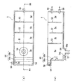
中間ろ過システムS2は、処理液に残存する夾雑物を浮遊させて回収するものであって、処理液を通過させる処理槽5と、マイクロバブルやナノバブル等の微細な気泡を発生するための気泡発生装置6と、浮遊物回収装置7と、を備える。処理槽5の内部には、上部に固定された2枚の仕切板51,53と、下部が固定された仕切板52が交互に設けられ、これにより処理槽5の内部が第1〜第4処理空間5a,5b,5c,5dへ仕切られている。図2をも参照して、第1処理空間5aの上流側(図2における左側)には更に受空間5eが設けられ、受空間5eの側面に流入口58が設けられている。受空間5eは処理槽5の幅方向(図2(a)における上下方向)全体に渡って延びると共に、その底面54は第1処理空間5aの底面50ひいては処理槽5内における処理液の液面よりも上方に位置する。また、底面54には、処理槽5の幅方向全体に渡って延びる板状の規制部材55が固定されている。この規制部材55は、底面54に固定された一端部55aと、一端部55aから第1処理空間5aに向けて斜め下方に延びる他端部55bと、を有し、全体として略へ字型縦断面を有して構成されている。また、第1処理空間5aの底面50における中央部位には、下向き円錐台形状の集積部56が凹設され、集積部56の底面56aには図示しない弁が設けられた筒状の排出口57が設けられている。第4処理空間5dの幅方向中央には垂直方向に配列された一対の排出口59が設けられている。
The intermediate filtration system S2 floats and collects contaminants remaining in the processing liquid. The intermediate filtration system S2 generates a bubble for generating a fine bubble such as microbubbles and nanobubbles, and a
ダーティタンク3から移送管L4を介して供給された処理液は、流入口58を介して最上流側の受空間54bに注入されたのち、規制板55を伝って第1処理空間5aへ流れ落ちる。その後、仕切板51の下部の空間から下流側の第2処理空間5bに流れ、下部が固定された仕切板52を乗り越えて下流側の第3処理空間5cに流れ、更に仕切板53の下部の空間から下流側の第4処理空間5dに流れた後に、流出口59及び移送管L5を介して後ろ過システムS3へ排出されるようになっている。
The processing liquid supplied from the
気泡発生装置6は、ポンプ61と、気体溶解タンク62と、処理槽5の第2処理空間5bに配置された気泡発生器63と、を備える。ポンプ61には配管64が接続され、配管64の取込口64aは処理槽5の第4処理空間5dに配置されている。ポンプ61が稼働すると、配管64の取込口64aから処理液が取り込まれ、気体溶解タンク62において空気が溶解された後に気泡発生器63から噴出され、これにより処理槽5内の処理液中に微細な気泡が発生する。ここで、廃液に含まれる加工液が水のみからなり、多価アルコール等の成分を含まない場合には、廃液中に微細な気泡を発生させても何らの効果も得られない。しかしながら、本実施形態における廃液に含まれる加工液は多価アルコールを含むことから、処理液(廃液)中に発生された微細な気泡は、処理液中の夾雑物に吸着し、これら夾雑物を液面に浮上させる。
The bubble generating device 6 includes a
浮遊物回収装置7は、処理槽5内の処理液のうち液面付近の表層液を吸い込んで回収するためのものであって、例えば広和エムテック株式会社製の鉱物油回収装置「ミニスキマ− MS−S」を用いることができる。この浮遊物回収装置7は、回収具71と、回収タンク72と、回収具71と回収タンク72とを連結する連結管73と、連結管73の長手方向途中部分に接続されたポンプ(図示せず)と、を備える。回収具71は処理槽5の第3処理空間5c内に設置され、その内部には上面が開口された回収空間が規定されている。また、回収具71にはフロートが設けられると共に、回収具71自体が液面レベルに応じて上下方向に伸縮自在とされており、常に処理液の液面付近に回収空間の上部開口が位置するようにされている。
The suspended matter recovery device 7 is for sucking and recovering the surface layer liquid near the liquid surface of the processing liquid in the
かかる構成において、前ろ過システムS1では除去されなかった処理液に含まれる比較的小さな夾雑物は、気泡発生装置6が発生する微細な気泡に吸着されて液面に浮上し、このようにして液面に浮上した夾雑物を含む処理液の表層液が、回収具71の上部開口から回収空間に回収され、ポンプの駆動によって連結管73を介して回収タンク72へ移送される。
In such a configuration, relatively small contaminants contained in the processing liquid that has not been removed by the prefiltration system S1 are adsorbed by the fine bubbles generated by the bubble generating device 6 and float on the liquid surface. The surface layer liquid of the processing liquid including the contaminants floating on the surface is collected in the collection space from the upper opening of the collection tool 71 and is transferred to the
後ろ過システムS3は、中間ろ過システムS2により夾雑物が取り除かれた後の処理液(「第2処理液」ともいう)から、残存する微細な夾雑物を更に除去するものであって、例えば、株式会社マツケン製のUF膜含油廃水処理システムを用いることができる。この後ろ過システムS3は、中間ろ過システムS2から排出された第2処理液が注入される濃縮タンク8と、チューブラー膜型の膜モジュール9と、第2処理液を濃縮タンク8から膜モジュール9へ供給する供給管L6と、供給管L6に接続されたポンプ81と、膜モジュール9を通過した第2処理液(濃縮液)を濃縮タンク8へ返送する返送管L7と、を備える。
The post-filtration system S3 further removes the remaining fine contaminants from the processing liquid after the impurities are removed by the intermediate filtration system S2 (also referred to as “second processing liquid”). A UF membrane oil-containing wastewater treatment system manufactured by Matsuken Corporation can be used. Thereafter, the filtration system S3 includes a
図示しないが、膜モジュール9は、ケーシングと、ケーシング内に収容されたチューブラー膜と、を備える。チューブラー膜は、多孔性チューブの内側に、孔径が0.005μm程度の微細な孔が多数設けられたウルトラフィルタ膜がコーティングされて構成されており、円筒状の膜面に対して水平に(即ち、チューブラー膜の長手方向に沿って)第2処理液が流れるクロスフローろ過方式を採用している。濃縮タンク8から供給された第2処理液はチューブラー膜の内部を通過した後に排出管L7を介して濃縮タンク8へ還元されるが、チューブラー膜に供給された第2処理液の一部は、濃縮タンク8へは還元されずにチューブラー膜の膜壁を通過してケーシング内へ排出される。そして、このようにチューブラー膜の膜壁を通過する際に微細な夾雑物が取り除かれ、ケーシング内に排出された処理液(「第3処理液」ともいう)は、移送管L8を介してクリーンタンク10へ排出される。
Although not shown, the
このように廃液を前ろ過システムS1、中間ろ過システムS2及び後ろ過システムS3で処理することにより、廃液に含まれる組成成分を減損することなく、粒子(研磨材や加工屑等の固形物)のみが完全に取り除かれる。 By treating the waste liquid with the pre-filtration system S1, the intermediate filtration system S2, and the post-filtration system S3 in this way, only particles (solid materials such as abrasives and processing waste) are not lost without deteriorating the composition components contained in the waste liquid. Is completely removed.
クリーンタンク10には、クリーンタン10内の第3処理液を撹拌するための撹拌ポンプ16が設けられ、この撹拌ポンプ16は、図示しない吸込口から吸い込んだ第3処理液を吐出口16aからクリーンタンク10の底面11に沿って斜め下方に向けて吐出することによって、クリーンタンク10内の第3処理液を縦回りに撹拌させる。また、後ろ過システムS3には、図示しない濃度センサと濃度調整装置が設けられている。濃度センサは、第3処理液に含まれる組成成分の濃度を検出するものであり、濃度調整装置は、濃度センサの検出結果に基づき、第3処理液に組成成分又は水を注入して、所定濃度の再生加工液を生成する。このようにして得られた再生加工液は、供給管L9を介してウォータージェット加工装置2へ供給される。なお、クリーンタンク10の底面11の水平方向に対する傾き角度についても、ダーティタンク3の場合と同様に、9°〜16°であるのが好ましく、12.5°であるのが更に好ましい。このような傾き角度とすることにより、クリーンタンク内の第3処理液(又は再生加工液)を均一に撹拌できる。
The
このように構成された加工液処理システム1では、ウォータージェット加工装置2から排出された廃液が次の様にして再生処理される。まず、廃液はウォータージェット加工装置2から移送管L1を介してダーティタンク3に供給される。ダーティタンク3内では撹拌ポンプ36の駆動により廃液が常に撹拌される。このように廃液を撹拌することによって、廃液に含まれる夾雑物はダーティタンク3内で沈殿することなく液体サイクロンフィルタ装置4へ送られることになる。よって、ダーティタンク3内で沈殿した夾雑物を除去するためのメンテナンスが不要となり、使い勝手を向上できる。
In the machining
ダーティタンク3から液体サイクロンフィルタ装置4へ送られた廃液は、シリンダ部41内を旋回しながら下降していく。このとき、廃液の旋回流に生じる遠心力の作用によって、加工液よりも比重の重い夾雑物はシリンダ部41の内壁に沿うことになり、重力によってスラッジ貯留部43へ排出される。一方、このようにして夾雑物が除去された後の廃液(処理液)は、シリンダ部41の下端で反転し、中心を旋回しながら上昇して流出部44を介して排出され、返送管L3を介してダーティタンク3へ返送される。
The waste liquid sent from the
このようにダーティタンク3と液体サイクロンフィルタ装置4の間で廃液を所定時間(又は所定量)循環させることによって、廃液から夾雑物を一定程度取り除く。このようにして一定程度の夾雑物が除去された廃液(処理液)は、移送管L4を介して中間ろ過システムS2へ送られる。
In this way, the waste liquid is circulated between the
中間ろ過システムS2では、処理液(廃液)は先ず処理槽5の受空間5eに注入され、規制板55の上面を伝って第1処理空間5aへ流れ落ち、仕切板51の下部の空間から第2処理空間5bに流れ込む。このように、処理液を一旦、受空間5eで受けて規制板55を伝って第1処理空間5a内へ流れ落とすことにより、処理液を第1処理空間5a内へ比較的しずかに供給でき、処理液を流入口58から直接第1処理空間5aへ注入させた場合と比較して、第1処理空間5a内で処理液が渦巻くのを抑制できる。また、このようにして第1処理空間5aに供給された処理液に含まれる比較的比重の重い夾雑物は沈殿して集積部56内に溜まる。このようにして集積部56内に溜まった夾雑物は、定期的に排出口57を介して排出される。なお、集積部56の側壁56bの水平方向に対する傾き角度α2は、30°〜60°とするのが好ましい。30°より小さいと、集積部56内に溜まった夾雑物が再び舞い上がり第2処理空間5bへ侵入するおそれがあり、また60°よりも小さいと、夾雑物が排出口57内で詰まりやすくなり、排出口57を介した夾雑物の除去に支障がでるおそれがあるためである。
In the intermediate filtration system S <b> 2, the processing liquid (waste liquid) is first injected into the receiving
上述の様に仕切板51の下部の空間から第2処理空間5bに流れ込んだ処理水は、第2処理空間5b内を上向きに流れる。このとき、処理液に含まれる比較的小さな夾雑物は、気泡発生装置6により発生された微細な気泡に吸着されて液面に浮上し、このように浮上した夾雑物を含む処理液の表層液は、第3処理空間5cにおいて浮上物回収装置7により回収される。このとき、第3処理空間5cと第4処理空間5dとは上端が固定された仕切板53により仕切られているため、液面に浮上した夾雑物は仕切板53により遮られて第4処理空間5dに侵入するのが阻止される。
As described above, the treated water flowing into the
また、本実施形態においては、気泡発生装置6は第2処理空間5b内にて処理液に気泡を発生させるのに対し、処理液を取り込むための取込口64aは第2処理空間5bとは仕切板52,53により仕切られた第4処理空間5dに配置されているため、気泡を効果的に夾雑物に付着させてこれを浮上させることができる。即ち、取込口64aを気泡発生器51と同じ第2処理空間5bに設けた場合には、第2処理空間5b内において処理液が撹拌されてしまい、気泡を効果的に夾雑物に付着させることができない。これに対し、本実施形態のように取込口64aを第2処理空間5bとは異なる処理空間に設けることによって、第2処理空間5b内における処理液の上向きの流れが乱れることがなく、夾雑物に付着した気泡を当該流れに乗せてスムーズに浮上させることができる。
In the present embodiment, the bubble generating device 6 generates bubbles in the processing liquid in the
このようにして比較的小さな夾雑物が除去された後の廃液(第2処理液)は、第4処理空間5dから移送管L5を介して後ろ過システムS3へ供給される。後ろ過システムS3では、第2処理液は一旦濃縮タンク8に集められた後に、ポンプ81の駆動によって膜モジュール9へ供給される。膜モジュール9へ供給された第2処理液の一部は、チューブラー膜の膜壁を通過することによって微細な粒子が除去された状態でケーシング内へ排出され、クリーンタンク10へ送られ、一方、残りの第2処理液はチューブラー膜の内部を通過して濃縮タンク8へ還元され、再び膜モジュール9へ供給される。
The waste liquid (second processing liquid) after removing relatively small impurities in this way is supplied from the
クリーンタンク10へ送られた廃液(第3処理液)は、上述したように内部で撹拌されながら濃度調整装置により濃度が調整され、再生加工液となってウォータージェット加工装置2へ還元され、研磨材と混合されて再びウォータージェット加工に供される。
As described above, the concentration of the waste liquid (third processing liquid) sent to the
このように、本実施形態の加工液処理システム1では、比較的大きな夾雑物から微細な夾雑物まで、複数の段階を経て除去するため、廃液に含まれる夾雑物を効率良く除去することができる。また、前ろ過システムS1では液体サイクロンフィルタ装置4を用いるので、バグフィルタや糸巻きフィルタを用いた場合と比較してフィルタ自体の交換頻度を減らすことができ、また機械式遠心分離器を用いた場合と比較して、製造コストを削減できる。
As described above, in the machining
また、本実施形態においては、加工液として多価アルコール等の成分を含む組成物を用いているため、気泡発生装置6により廃液中に微細な気泡を発生させることによって、夾雑物を効果的に分離して除去することができる。 Moreover, in this embodiment, since the composition containing components, such as a polyhydric alcohol, is used as a processing liquid, by generating a fine bubble in a waste liquid with the bubble generator 6, a foreign substance is effectively removed. It can be separated and removed.
更に、後ろ過システムS3ではチューブラー膜型の膜モジュール9を用いるため、ペーパーフィルタを用いた場合におけるフィルタの交換にかかる費用やコストが発生せず、また中空フィルタを用いた場合における頻繁な目詰まりの発生もない。また、比較的大きな夾雑物から小さな夾雑物まで、前ろ過システムS1及び中間ろ過システムS2において予め除去しておくことにより、膜モジュール9にかかる負荷を軽減することができ、膜モジュール9の寿命を向上できる。
Further, since the tubular membrane
以上、本発明の実施形態に係る加工液処理システムについて添付の図面を参照して説明したが、本発明はかかる実施形態に限定されず、本発明の範囲を逸脱することなく種々の変形乃至修正が可能である。 The working fluid treatment system according to the embodiment of the present invention has been described above with reference to the accompanying drawings. However, the present invention is not limited to the embodiment, and various modifications and corrections can be made without departing from the scope of the present invention. Is possible.
例えば、上記実施形態においては、前ろ過システムS1と、中間ろ過システムS2と、後ろ過システムS3の3つの処理システムを用いて廃液を処理したが、中間ろ過システムS2を省略し、前ろ過システムS1で処理された廃液を直接後ろ過システムS3へ供給し、膜モジュール9にて処理するようにしてもよい。
For example, in the said embodiment, although waste liquid was processed using three processing systems, prefiltration system S1, intermediate filtration system S2, and postfiltration system S3, intermediate filtration system S2 is abbreviate | omitted and prefiltration system S1. The waste liquid treated in
また、ダーティタンク31の底面中央部に例えばボールバルブ等の排出部を設けてもよい。このようにダーティタンク31の底面中央部に排出部を設けておくことにより、仮にダーティタンク31内で夾雑物が沈殿しても、これを排出部を介して除去することができる。また、この場合においても、上述したようにダーティタンク3の底面31の傾き角度αを9°よりも大きくしているので、排出部を介した夾雑物の除去を容易にできる。
Further, a discharge unit such as a ball valve may be provided at the center of the bottom surface of the
1 加工液処理システム
2 ウォータージェット加工装置
3 ダーティタンク
4 液体サイクロンフィルタ装置
5 処理槽
6 気泡発生装置
7 浮遊物回収装置
8 濃縮タンク
9 膜モジュール
10 クリーンタンク
S1 前ろ過システム
S2 中ろ過理システム
S3 後ろ過システム
DESCRIPTION OF
Claims (7)
前記使用済加工液を貯蔵する第1タンクと、前記第1タンクから供給された前記使用済加工液から夾雑物を除去して処理液を生成する液体サイクロンフィルタ装置と、
前記処理液に残存する夾雑物を除去するチューブラー膜型の膜モジュールと、を備えることを特徴とする加工液処理システム。 A processing fluid processing system for processing a used processing fluid discharged from a water jet processing device in a reusable manner,
A first tank for storing the used processing liquid; and a liquid cyclone filter device for removing impurities from the used processing liquid supplied from the first tank to generate a processing liquid;
And a tubular membrane-type membrane module for removing impurities remaining in the treatment solution.
前記使用済加工液は、加工液と、被加工物を加工する際に生じる加工屑と、を含み、前記加工液は多価アルコールを含み、
前記気泡発生装置から発生した前記気泡は、前記処理液に残存する夾雑物に付着して前記処理液の液面に浮上し、前記浮遊物回収装置は、前記液面に浮上した前記夾雑物を回収し、
前記処理槽を通過した前記処理液は前記膜モジュールへ移送されることを特徴とする請求項1又は2に記載の加工液処理システム。 A treatment tank for allowing the treatment liquid generated by the liquid cyclone filter device to pass therethrough, a bubble generation device for generating fine bubbles in the treatment liquid in the treatment tank, and a suspended matter recovery device,
The used processing liquid includes a processing liquid and processing waste generated when processing the workpiece, and the processing liquid includes a polyhydric alcohol,
The bubbles generated from the bubble generating device adhere to foreign matters remaining in the processing liquid and float on the liquid surface of the processing liquid, and the floating matter collecting device removes the foreign matters floating on the liquid surface. Recovered,
The processing liquid processing system according to claim 1, wherein the processing liquid that has passed through the processing tank is transferred to the membrane module.
前記処理水は、前記第1処理空間に供給されて、前記仕切板の下側と前記仕切板の上側とを交互に通って前記第1処理空間から下流側の前記第4処理空間に向けて流れ、
前記気泡発生装置は、前記処理槽内の前記処理液に浸漬されて前記処理液を吸入するための吸入口と、前記処理槽内の前記処理液に前記微細な気泡を発生せるための気泡発生器と、を備え、
前記吸入口は前記第4処理空間に配置され、前記気泡発生器は前記第2処理空間に配置されることを特徴とする請求項3に記載の加工液処理システム。 The internal space of the processing tank is partitioned into a first processing space, a second processing space, a third processing space, and a fourth processing space in order from the upstream side by a plurality of partition plates.
The treated water is supplied to the first treatment space, and alternately passes through the lower side of the partition plate and the upper side of the partition plate toward the fourth treatment space on the downstream side from the first treatment space. flow,
The bubble generating device includes a suction port that is immersed in the treatment liquid in the treatment tank and sucks the treatment liquid, and a bubble generation that generates the fine bubbles in the treatment liquid in the treatment tank. And equipped with
The processing liquid processing system according to claim 3, wherein the suction port is disposed in the fourth processing space, and the bubble generator is disposed in the second processing space.
前記回収具は前記処理槽の前記第3処理空間に配置されていることを特徴とする請求項4に記載の加工液処理システム。 The floating substance recovery device is a recovery tool for recovering the impurities floating on the liquid surface, a connection pipe having one end connected to the recovery tool, a recovery tank to which the other end of the connection pipe is connected, The contaminants recovered by the recovery tool are transferred to the recovery tank via the connection pipe,
The processing liquid processing system according to claim 4, wherein the recovery tool is disposed in the third processing space of the processing tank.
The processing liquid treatment system according to claim 4, wherein a bottom frustoconical accumulation portion is provided on a bottom surface of the first treatment space.
Priority Applications (1)
| Application Number | Priority Date | Filing Date | Title |
|---|---|---|---|
| JP2015046675A JP6496931B2 (en) | 2015-03-10 | 2015-03-10 | Processing fluid treatment system |
Applications Claiming Priority (1)
| Application Number | Priority Date | Filing Date | Title |
|---|---|---|---|
| JP2015046675A JP6496931B2 (en) | 2015-03-10 | 2015-03-10 | Processing fluid treatment system |
Publications (2)
| Publication Number | Publication Date |
|---|---|
| JP2016165772A true JP2016165772A (en) | 2016-09-15 |
| JP6496931B2 JP6496931B2 (en) | 2019-04-10 |
Family
ID=56897498
Family Applications (1)
| Application Number | Title | Priority Date | Filing Date |
|---|---|---|---|
| JP2015046675A Active JP6496931B2 (en) | 2015-03-10 | 2015-03-10 | Processing fluid treatment system |
Country Status (1)
| Country | Link |
|---|---|
| JP (1) | JP6496931B2 (en) |
Cited By (2)
| Publication number | Priority date | Publication date | Assignee | Title |
|---|---|---|---|---|
| JP2020097081A (en) * | 2018-12-18 | 2020-06-25 | 株式会社スギノマシン | Used abrasive material separation system |
| KR20210099922A (en) | 2020-02-05 | 2021-08-13 | 정현서 | Smart glass using biohealth technology |
Citations (9)
| Publication number | Priority date | Publication date | Assignee | Title |
|---|---|---|---|---|
| JPS62199361A (en) * | 1986-02-27 | 1987-09-03 | Fuji Photo Film Co Ltd | Slurry circulating method |
| JPH0751514A (en) * | 1993-08-18 | 1995-02-28 | Okamoto Kosaku Kikai Seisakusho:Kk | Filter apparatus |
| JPH08243923A (en) * | 1995-03-07 | 1996-09-24 | Nippon Steel Corp | Working liquid and water jet working device using it |
| JP2003305422A (en) * | 2002-04-18 | 2003-10-28 | Fuji Kikai:Kk | Wet blasting device having high-pressure cleaning function |
| JP2004160641A (en) * | 2002-10-22 | 2004-06-10 | Kontekku For You:Kk | Water jet polishing material recovery device |
| JP3133412U (en) * | 2007-04-06 | 2007-07-12 | マトヤ技研工業株式会社 | Coolant liquid recycling system |
| JP2010105053A (en) * | 2008-10-28 | 2010-05-13 | Sodick Co Ltd | Composite processing equipment |
| JP2010201574A (en) * | 2009-03-04 | 2010-09-16 | Honda Motor Co Ltd | Liquid honing device |
| JP2012178418A (en) * | 2011-02-25 | 2012-09-13 | Nomura Micro Sci Co Ltd | Method and apparatus for collecting polishing agent |
-
2015
- 2015-03-10 JP JP2015046675A patent/JP6496931B2/en active Active
Patent Citations (9)
| Publication number | Priority date | Publication date | Assignee | Title |
|---|---|---|---|---|
| JPS62199361A (en) * | 1986-02-27 | 1987-09-03 | Fuji Photo Film Co Ltd | Slurry circulating method |
| JPH0751514A (en) * | 1993-08-18 | 1995-02-28 | Okamoto Kosaku Kikai Seisakusho:Kk | Filter apparatus |
| JPH08243923A (en) * | 1995-03-07 | 1996-09-24 | Nippon Steel Corp | Working liquid and water jet working device using it |
| JP2003305422A (en) * | 2002-04-18 | 2003-10-28 | Fuji Kikai:Kk | Wet blasting device having high-pressure cleaning function |
| JP2004160641A (en) * | 2002-10-22 | 2004-06-10 | Kontekku For You:Kk | Water jet polishing material recovery device |
| JP3133412U (en) * | 2007-04-06 | 2007-07-12 | マトヤ技研工業株式会社 | Coolant liquid recycling system |
| JP2010105053A (en) * | 2008-10-28 | 2010-05-13 | Sodick Co Ltd | Composite processing equipment |
| JP2010201574A (en) * | 2009-03-04 | 2010-09-16 | Honda Motor Co Ltd | Liquid honing device |
| JP2012178418A (en) * | 2011-02-25 | 2012-09-13 | Nomura Micro Sci Co Ltd | Method and apparatus for collecting polishing agent |
Cited By (3)
| Publication number | Priority date | Publication date | Assignee | Title |
|---|---|---|---|---|
| JP2020097081A (en) * | 2018-12-18 | 2020-06-25 | 株式会社スギノマシン | Used abrasive material separation system |
| JP7078527B2 (en) | 2018-12-18 | 2022-05-31 | 株式会社スギノマシン | Used abrasive separation system |
| KR20210099922A (en) | 2020-02-05 | 2021-08-13 | 정현서 | Smart glass using biohealth technology |
Also Published As
| Publication number | Publication date |
|---|---|
| JP6496931B2 (en) | 2019-04-10 |
Similar Documents
| Publication | Publication Date | Title |
|---|---|---|
| JP5564021B2 (en) | Oil-containing wastewater treatment system | |
| KR101281514B1 (en) | A pressure float type polluted water treatment method using microbubble unit and slanted plate sturcture | |
| JP6170552B2 (en) | Seawater desalination apparatus and method | |
| JP5269749B2 (en) | Filtration device cleaning method | |
| ES2937166T3 (en) | Multilayer Media Bed Filter with Enhanced Backwash | |
| JP6381412B2 (en) | Seawater desalination apparatus and method | |
| KR101336169B1 (en) | Water purifying apparatus using sedimentation and dissolved air flotation | |
| JP2019209241A (en) | Device and method of decontaminating scrubber effluent, and salinity difference power generation system | |
| JP4181440B2 (en) | Filtration apparatus and filtration method using the same | |
| JP6496931B2 (en) | Processing fluid treatment system | |
| JP5470658B2 (en) | Treatment liquid purification device | |
| JP6580338B2 (en) | Film processing apparatus and film processing method | |
| JP5464836B2 (en) | Cleaning device and cleaning method | |
| US6129839A (en) | Separation system for immiscible liquids | |
| JP2004050145A (en) | Apparatus for separating oil/water for bilge containing fine suspended solid | |
| JP4171248B2 (en) | Filtration device using floating filter media | |
| JP2021079361A (en) | Purifier and purification method of cleaning fluid | |
| JPH11309446A (en) | Composite water purifying device | |
| JP2007000712A (en) | Solid-liquid separating device | |
| JP2664877B2 (en) | Oil-water separator | |
| JP3566945B2 (en) | Cavitation generator | |
| JPH0889709A (en) | Separating and removing method of mixture in liquid | |
| CN214192791U (en) | Cutting fluid clarification plant | |
| JP2005046684A (en) | Treatment method of soluble organic matter-containing liquid | |
| KR101106842B1 (en) | A waer-purifying device |
Legal Events
| Date | Code | Title | Description |
|---|---|---|---|
| A621 | Written request for application examination |
Free format text: JAPANESE INTERMEDIATE CODE: A621 Effective date: 20180226 |
|
| A521 | Request for written amendment filed |
Free format text: JAPANESE INTERMEDIATE CODE: A821 Effective date: 20180226 |
|
| A977 | Report on retrieval |
Free format text: JAPANESE INTERMEDIATE CODE: A971007 Effective date: 20181113 |
|
| A131 | Notification of reasons for refusal |
Free format text: JAPANESE INTERMEDIATE CODE: A131 Effective date: 20181120 |
|
| A521 | Request for written amendment filed |
Free format text: JAPANESE INTERMEDIATE CODE: A523 Effective date: 20190107 |
|
| TRDD | Decision of grant or rejection written | ||
| A01 | Written decision to grant a patent or to grant a registration (utility model) |
Free format text: JAPANESE INTERMEDIATE CODE: A01 Effective date: 20190212 |
|
| A61 | First payment of annual fees (during grant procedure) |
Free format text: JAPANESE INTERMEDIATE CODE: A61 Effective date: 20190218 |
|
| R150 | Certificate of patent or registration of utility model |
Ref document number: 6496931 Country of ref document: JP Free format text: JAPANESE INTERMEDIATE CODE: R150 |
|
| R250 | Receipt of annual fees |
Free format text: JAPANESE INTERMEDIATE CODE: R250 |
|
| R250 | Receipt of annual fees |
Free format text: JAPANESE INTERMEDIATE CODE: R250 |
|
| S111 | Request for change of ownership or part of ownership |
Free format text: JAPANESE INTERMEDIATE CODE: R313117 |
|
| R250 | Receipt of annual fees |
Free format text: JAPANESE INTERMEDIATE CODE: R250 |