JP2016139516A - Luminaire - Google Patents
Luminaire Download PDFInfo
- Publication number
- JP2016139516A JP2016139516A JP2015013656A JP2015013656A JP2016139516A JP 2016139516 A JP2016139516 A JP 2016139516A JP 2015013656 A JP2015013656 A JP 2015013656A JP 2015013656 A JP2015013656 A JP 2015013656A JP 2016139516 A JP2016139516 A JP 2016139516A
- Authority
- JP
- Japan
- Prior art keywords
- light
- light source
- mirror
- wavelength
- less
- Prior art date
- Legal status (The legal status is an assumption and is not a legal conclusion. Google has not performed a legal analysis and makes no representation as to the accuracy of the status listed.)
- Pending
Links
Images


Abstract
Description
本発明は、照明装置に関する。 The present invention relates to a lighting device.
近年は、鏡と一体になった照明装置が普及している。このような照明装置に求められる特性に、光の波長スペクトルが太陽光に近いこと(演色性が高いこと)、使用者が不快な眩しさ(グレア)を感じないこと、などがある。一方、近年は照明装置の光源として、LED(Light Emitting Diode)が用いられるようになっている。一方、LEDはピーク波長における光の強度が強く、眩しさを感じることや太陽光と波長スペクトルが異なっていたりする。 In recent years, lighting devices integrated with mirrors have become widespread. The characteristics required for such an illuminating device include that the wavelength spectrum of light is close to that of sunlight (high color rendering), and that the user does not feel unpleasant glare. On the other hand, in recent years, an LED (Light Emitting Diode) has been used as a light source of an illumination device. On the other hand, the intensity of light at the peak wavelength is strong, and the LED feels dazzling or has a wavelength spectrum different from that of sunlight.
これに対して、特許文献1には、半値幅が30nmで波長455nmにピークを有して青色光を放射するLED素子と、半値幅が130nmで波長550nmにピークを有する蛍光体と、半値幅が95nmで波長640nmにピークを有する蛍光体とを備える照明装置が記載されている。特許文献1によれば、LEDを光源として用いた場合においても、演色性を高めることができる、とされている。
In contrast,
本発明者は、鏡を有する照明装置において、他の方法を用いて演色性を高めることを検討した。すなわち、本発明が解決しようとする課題としては、鏡を有する照明装置において、演色性を高めることが一例として挙げられる。 The present inventor has studied to improve color rendering using another method in an illumination device having a mirror. That is, as a problem to be solved by the present invention, increasing the color rendering properties in an illumination device having a mirror is an example.
請求項1に記載の発明は、鏡と、
前記鏡の隣に配置された光源と、
前記光源の前方に配置され、前記光源からの光を透過しつつ拡散する拡散部材と、
を備え、
前記光源からの光において、波長スペクトルのピーク波長は、400nm以下であり、
前記拡散部材を透過した光の色温度は4500K以上5500K以下であり、
前記拡散部材を透過した光のうち、波長が400nm以上720nm以下の範囲である第1範囲における光の強度が基準値以上である照明装置が提供される。
The invention according to
A light source disposed next to the mirror;
A diffusion member disposed in front of the light source and diffusing while transmitting light from the light source;
With
In the light from the light source, the peak wavelength of the wavelength spectrum is 400 nm or less,
The color temperature of the light transmitted through the diffusing member is 4500K or more and 5500K or less,
Of the light transmitted through the diffusing member, there is provided an illuminating device in which the intensity of light in a first range in which the wavelength is in the range of 400 nm to 720 nm is greater than or equal to a reference value.
以下、本発明の実施の形態について、図面を用いて説明する。尚、すべての図面において、同様な構成要素には同様の符号を付し、適宜説明を省略する。 Hereinafter, embodiments of the present invention will be described with reference to the drawings. In all the drawings, the same reference numerals are given to the same components, and the description will be omitted as appropriate.
図1は、実施形態に係る照明装置10の構成を示す平面図である。図2は図1のA−A断面図である。実施形態に係る照明装置10は、鏡110、光源122、及び拡散部材128を備える。鏡110は、光反射面が第1の方向(図1に垂直な方向)を向いている。光源122は鏡110の隣に配置されている。拡散部材128は光源122の前方に配置され、光源122からの光を透過しつつ拡散する。光源122からの光において、波長スペクトルのピーク波長が400nm以下である。拡散部材128を透過した光の色温度は、4500K以上5500K以下である。そして、拡散部材128を透過した光のうち、波長が400nm以上720nm以下の範囲である第1範囲における光の強度が基準値以上になっている。以下、詳細に説明する。
FIG. 1 is a plan view showing a configuration of a
照明装置10は保持部材100を備えている。鏡110は保持部材100の第1面に取り付けられている。また、保持部材100のうち鏡110の隣に位置する領域には、照明部120が設けられている。照明部120の光射出面は、保持部材100の第1面から露出している。このため、照明部120は、鏡110が向いている方向に光を放射することができる。なお、本図に示す例では、保持部材100の第1面のうち鏡110が取り付けられている部分と、保持部材100の第1面のうち照明部120が設けられている部分は、同一の平面となっている。ただし、これら2つの部分は互いに異なる平面であってもよい。言い換えると、照明部120は、鏡110の垂線と交わる方向を向いていてもよい。この場合、照明部120の垂線と鏡110の垂線とがなす角度は、例えば0°超45°以下である。
The
本図に示す例において、照明部120は、鏡110の両隣のそれぞれに設けられている。また、保持部材100には、複数の照明部120が上下に並んで設けられている。
In the example shown in the drawing, the
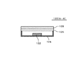
次に、図2を用いて照明部120の構成を説明する。本図に示すように、照明部120は、光源122、リフレクタ124、光フィルタ126、及び拡散部材128を有している。
Next, the structure of the
光源122は、例えば発光ダイオード(LED)である。また、光源122の波長スペクトルにおいて、例えば図3に示すように、ピーク波長は400nm以下である。このピーク波長以外の波長スペクトルは、例えばおおよそ次のようなものである。可視光領域の420〜450nmの波長は抑えられており、赤近傍の600〜650nmの波長は強められている。更に光の強度は、いずれの部分においても、上記ピーク波長の強度の基準値の50%以上である。これは、太陽光の波長スペクトルと類似した形状となる。特に可視光領域の420〜450nmの波長は、人間の肌による表面反射が大きく、この付近の波長を抑えることで化粧を行うときのユーザが感じるグレアを抑えことができる。可視光領域の600〜650nmの波長は、太陽光の下で人間の肌を見るものと似た条件をつくることができる。以上の条件をみたすと、鏡を有する照明装置でメークを行うときの演色性を高め、グレアを抑えることができる。
The
光源122は、リフレクタ124の凹部内に配置されている。リフレクタ124の凹部の内面は、光反射膜(例えばAl膜などの金属膜)で覆われている。また、リフレクタ124の凹部の上面には、光フィルタ126及び拡散部材128が設けられている。
The
拡散部材128は、光源122から放射された光を透過しつつ拡散する。拡散部材128が設けられることにより、照明部120から放射される光は、グレアを抑え柔らかく感じられる。
The diffusing
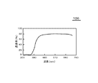
光フィルタ126は光源122と拡散部材128の間に位置している。光フィルタ126は、短波長カットフィルタ(例えば紫外線カットフィルム)であり、例えば図4に示すように、光源122のピーク波長の光成分をある程度カットする。その結果、拡散部材128から放射される光の色温度は、4500K以上5500K以下になる。また、拡散部材128から放射される光において、上記した第1範囲(400nm以上720nm以下の範囲)における光の強度の基準値は、いずれの部分においても、上記ピーク波長の強度の50%以上である。これにより、太陽光の波長スペクトルと類似した形状となる。ここで、拡散部材128から放射される光において、第1範囲(400nm以上720nm以下の範囲)における光の強度は、少なくとも一部において、上記ピーク波長の強度の100%以上であってもよい。
The
なお、図2において、一つのリフレクタ124の内部には一つの光源122が配置されている。ただし、一つのリフレクタ124の内部には複数の光源122が配置されていてもよい。
In FIG. 2, one
以上、本実施形態によれば、光源122からの光において、波長スペクトルのピーク波長は、400nm以下である。そして、拡散部材を透過した光の色温度は4500K以上5500K以下であり、またこの光のうち、波長が400nm以上720nm以下の範囲である第1範囲における光の強度が基準値以上である。このため、鏡を有する照明装置10において、演色性を高めることができる。
As described above, according to the present embodiment, in the light from the
(変形例1)
図5は、変形例1に係る照明装置10の構成を示す図である。本変形例に係る照明装置10は、以下の点を除いて、実施形態に係る照明装置10と同様の構成である。
(Modification 1)
FIG. 5 is a diagram illustrating a configuration of the
まず、照明部120は、保持部材100ではなく保持部材102に取り付けられている。そして、保持部材102は、取付部材104を用いて、保持部材100の縁に取り付けられている。取付部材104は、例えば蝶番であり、保持部材102を、保持部材100に対して回転移動できるように取り付けている。
First, the
本変形例1によっても、鏡を有する照明装置10において、演色性を高めることができる。
Also according to the first modification, color rendering can be enhanced in the
(変形例2)
図1で説明した鏡を有する照明装置10において、ハーフミラー機能を有する拡散部材128を利用してもよい。光源122が非発光のときは、照明装置10全面が鏡面となる。そして、使用者の動きに合わせて複数の照明部120をそれぞれ別々に駆動することで、使用者の動きに合わせた照明を行うことができる。例えば、背の高い使用者や背の低い使用者それぞれに合った照明を行うことができる。また、使用者が照明装置10から離れて全身を映すとき、逆に近づいたときに合った照明条件を設定することができる。この変形例2においても、照明装置10は、演色性を高めることができる。
(Modification 2)
In the illuminating
以上、図面を参照して実施形態及び実施例について述べたが、これらは本発明の例示であり、上記以外の様々な構成を採用することもできる。 As mentioned above, although embodiment and the Example were described with reference to drawings, these are illustrations of this invention and can also employ | adopt various structures other than the above.
10 照明装置
100 保持部材
102 保持部材
104 取付部材
110 鏡
120 照明部
122 光源
126 光フィルタ
128 拡散部材
DESCRIPTION OF
Claims (4)
前記鏡の隣に配置された光源と、
前記光源の前方に配置され、前記光源からの光を透過しつつ拡散する拡散部材と、
を備え、
前記光源からの光において、波長スペクトルのピーク波長は、400nm以下であり、
前記拡散部材を透過した光の色温度は4500K以上5500K以下であり、
前記拡散部材を透過した光のうち、波長が400nm以上720nm以下の範囲である第1範囲における光の強度が基準値以上である照明装置。 With a mirror,
A light source disposed next to the mirror;
A diffusion member disposed in front of the light source and diffusing while transmitting light from the light source;
With
In the light from the light source, the peak wavelength of the wavelength spectrum is 400 nm or less,
The color temperature of the light transmitted through the diffusing member is 4500K or more and 5500K or less,
The illuminating device whose intensity | strength of the light in the 1st range whose wavelength is the range of 400 nm or more and 720 nm or less among the light which permeate | transmitted the said diffusing member is more than a reference value.
前記第1範囲における光の強度の基準値は、前記拡散部材から放射された光における前記ピーク波長の強度の50%以上である照明装置。 The lighting device according to claim 1.
The reference value of the light intensity in the first range is an illumination device that is 50% or more of the intensity of the peak wavelength in the light emitted from the diffusing member.
前記光源の前方に配置され、前記ピーク波長の光を吸収する光フィルタを備える照明装置。 The lighting device according to claim 2,
An illumination device including an optical filter that is disposed in front of the light source and absorbs light having the peak wavelength.
前記光源はLEDを有する照明装置。 The lighting device according to claim 3.
The light source is an illumination device having an LED.
Priority Applications (1)
| Application Number | Priority Date | Filing Date | Title |
|---|---|---|---|
| JP2015013656A JP2016139516A (en) | 2015-01-27 | 2015-01-27 | Luminaire |
Applications Claiming Priority (1)
| Application Number | Priority Date | Filing Date | Title |
|---|---|---|---|
| JP2015013656A JP2016139516A (en) | 2015-01-27 | 2015-01-27 | Luminaire |
Publications (2)
| Publication Number | Publication Date |
|---|---|
| JP2016139516A true JP2016139516A (en) | 2016-08-04 |
| JP2016139516A5 JP2016139516A5 (en) | 2018-01-11 |
Family
ID=56560397
Family Applications (1)
| Application Number | Title | Priority Date | Filing Date |
|---|---|---|---|
| JP2015013656A Pending JP2016139516A (en) | 2015-01-27 | 2015-01-27 | Luminaire |
Country Status (1)
| Country | Link |
|---|---|
| JP (1) | JP2016139516A (en) |
Citations (4)
| Publication number | Priority date | Publication date | Assignee | Title |
|---|---|---|---|---|
| JP2004352928A (en) * | 2003-05-30 | 2004-12-16 | Mitsubishi Chemicals Corp | Light emitting equipment and lighting unit |
| JP2007266579A (en) * | 2006-02-28 | 2007-10-11 | Toshiba Lighting & Technology Corp | Light emitting device |
| JP2008272333A (en) * | 2007-05-02 | 2008-11-13 | Ya Man Ltd | Triple mirror apparatus |
| JP2013058473A (en) * | 2011-08-18 | 2013-03-28 | Panasonic Corp | Illumination device |
-
2015
- 2015-01-27 JP JP2015013656A patent/JP2016139516A/en active Pending
Patent Citations (4)
| Publication number | Priority date | Publication date | Assignee | Title |
|---|---|---|---|---|
| JP2004352928A (en) * | 2003-05-30 | 2004-12-16 | Mitsubishi Chemicals Corp | Light emitting equipment and lighting unit |
| JP2007266579A (en) * | 2006-02-28 | 2007-10-11 | Toshiba Lighting & Technology Corp | Light emitting device |
| JP2008272333A (en) * | 2007-05-02 | 2008-11-13 | Ya Man Ltd | Triple mirror apparatus |
| JP2013058473A (en) * | 2011-08-18 | 2013-03-28 | Panasonic Corp | Illumination device |
Similar Documents
| Publication | Publication Date | Title |
|---|---|---|
| US9476556B2 (en) | Vehicle headlight assembly | |
| JP6746397B2 (en) | Vehicle lighting | |
| JP6792427B2 (en) | Vehicle lighting | |
| JP5659835B2 (en) | Vehicle lighting | |
| KR101241678B1 (en) | Rear lamp for vehicle | |
| US9915403B2 (en) | Vehicle lamp | |
| CN208332157U (en) | Multi-panel lens | |
| EP1710495A1 (en) | Antidazzle device for led light sources | |
| JP2010287397A (en) | Lighting fixture for vehicle | |
| JP2010040322A (en) | Lighting fixture for vehicle | |
| JP5368233B2 (en) | Vehicle lighting | |
| JP5418746B2 (en) | Vehicle lighting | |
| KR20150062570A (en) | Head Lamp for Vehicle | |
| RU2657242C2 (en) | Lighting device and method of reducing uncomfortable glare | |
| RU2692685C2 (en) | Luminaire | |
| JP2015076249A (en) | Vehicular lighting fixture | |
| US20190004238A1 (en) | Optical module and illumination apparatus | |
| JP2015076310A (en) | Vehicle lighting appliance | |
| RU2630684C2 (en) | Lamp for outdoor lighting | |
| JP2016139516A (en) | Luminaire | |
| JP6435670B2 (en) | Vehicle lighting | |
| JP6303734B2 (en) | Vehicle lighting | |
| JP2004227981A (en) | Vehicular lamp | |
| JP6793519B2 (en) | Vehicle lighting | |
| US10119678B2 (en) | Lighting fixture |
Legal Events
| Date | Code | Title | Description |
|---|---|---|---|
| A521 | Request for written amendment filed |
Free format text: JAPANESE INTERMEDIATE CODE: A523 Effective date: 20171117 |
|
| A621 | Written request for application examination |
Free format text: JAPANESE INTERMEDIATE CODE: A621 Effective date: 20171117 |
|
| A131 | Notification of reasons for refusal |
Free format text: JAPANESE INTERMEDIATE CODE: A131 Effective date: 20180717 |
|
| A02 | Decision of refusal |
Free format text: JAPANESE INTERMEDIATE CODE: A02 Effective date: 20190205 |