JP2016138922A - Information sheet, information sheet manufacturing method, and information display body - Google Patents
Information sheet, information sheet manufacturing method, and information display body Download PDFInfo
- Publication number
- JP2016138922A JP2016138922A JP2015012222A JP2015012222A JP2016138922A JP 2016138922 A JP2016138922 A JP 2016138922A JP 2015012222 A JP2015012222 A JP 2015012222A JP 2015012222 A JP2015012222 A JP 2015012222A JP 2016138922 A JP2016138922 A JP 2016138922A
- Authority
- JP
- Japan
- Prior art keywords
- layer
- information
- film layer
- resin
- transparent film
- Prior art date
- Legal status (The legal status is an assumption and is not a legal conclusion. Google has not performed a legal analysis and makes no representation as to the accuracy of the status listed.)
- Granted
Links
Images





Landscapes
- Laminated Bodies (AREA)
Abstract
Description
本発明は、多様な被着体に吸着または粘着が可能な情報シートに関する。また、本発明は、情報シートが被着体に吸着または粘着した情報表示体にも関する。 The present invention relates to an information sheet that can be adsorbed or adhered to various adherends. The present invention also relates to an information display body in which an information sheet is adsorbed or adhered to an adherend.
従来、壁面、ガラス面、柱、掲示板、ロッカー、書棚等の硬質の被着体に、印刷により作製したポスター、広告等のシート状媒体を貼り付ける際に、接着剤、粘着テープ等が利用されてきた。近年、こうした広告等のシート状媒体についても、資材リサイクルの観点から使用後も再利用可能な状態で容易に回収できるものが望まれている。しかし、接着剤や両面テープを使用した場合、広告等を被着体から剥離するのが容易ではなく、破れて再利用ができない場合がある。また、広告等に接着剤や粘着剤が残っていると資源としてのリサイクルも困難となり、結局、一度使用した後は大半が廃棄物として処理されているという問題がある。更に、広告等のシート状媒体を、接着剤や両面テープを使用して壁面や柱等の被着体に貼り付けると、これを剥がした後に被着体側にも糊等が残ってしまったり、被着体の表面の塗装が剥れたりしてしまうという問題もあった。 Conventionally, adhesives, pressure-sensitive adhesive tapes, etc. have been used to attach printed media such as posters and advertisements to hard substrates such as walls, glass surfaces, pillars, bulletin boards, lockers and bookcases. I came. In recent years, it has been desired that such a sheet-like medium such as an advertisement can be easily collected in a reusable state after use from the viewpoint of material recycling. However, when an adhesive or a double-sided tape is used, it is not easy to peel off advertisements and the like from the adherend, and it may be torn and cannot be reused. In addition, if adhesives or adhesives remain in advertisements, recycling as resources becomes difficult, and eventually there is a problem that most of them are treated as waste after being used once. Furthermore, if a sheet-like medium such as an advertisement is attached to an adherend such as a wall surface or a pillar using an adhesive or a double-sided tape, glue or the like may remain on the adherend side after peeling it, There was also a problem that the surface of the adherend peeled off.
これに対して、広告等のシート状媒体を静電吸着力により被着体へ貼り付ける技術が提案されている(下記特許文献1参照)。特許文献1には、支持体層と不透明なラベル層が互いに静電吸着したシートが記載されており、使用時にラベル層を支持体層から剥離して、その剥離して露わになった面が被着体表面と接するようにラベル層を貼り付けて静電吸着させることが説明されている。特許文献1によると、剥離前のシートは剥離前には外部に静電吸着力を発現しないために、特に印刷工程でロールへの貼り付きやシート同士のブロッキング等のトラブルが発生し難いという利点があり、また、ハンドリング性が良好で、多様な印刷方式にも対応できるとされている。また、特許文献1によると、被着体に貼り付けた後は、環境湿度に影響されずに長期にわたって静電吸着力が持続し、また、使用後は容易に剥がすことができるという利点があるとされている。
On the other hand, the technique which affixes sheet-like media, such as an advertisement, to a to-be-adhered body by an electrostatic attraction force is proposed (refer the following patent document 1).
しかしながら、特許文献1のシートでは、被着体へ貼り付けるためにシートからラベル層を剥がした後に、支持体層が手元に残ってしまうという問題があった。このため、ラベル層を被着体へ貼り付けた後に支持体層を回収し、運搬して処理する手間がかかっていた。したがって、無駄になる資材が多量に出てしまう事態を回避することが望まれていた。
However, the sheet of
一方、ラベル層には様々な情報を印刷することが求められているが、なかでも地図を含む情報の場合は、共通の地図をベースにしながら個別の目的に応じた多様な情報を付加した印刷を行うことが必要とされる場合が多い。例えば、店舗等の場所を指し示す印刷や、目的地までの経路を示す印刷等は、共通の地図を印刷した上に更に重ねて印刷したり、共通の地図を元から改変して印刷したりしている。しかしながら、多種多様なニーズに応えるために、それぞれのニーズに合致する情報を付加した地図をその都度印刷するのは効率が悪く、手間もかかる。このため、地図そのものを共通して使用しながら、各ニーズに対応した個別の情報を地図に簡単に付加できるようなシートがあれば便利である。しかしながら、そのような便利なシートは開発されるに至っていない。 On the other hand, it is required to print various kinds of information on the label layer, but in the case of information including maps, printing with various information according to individual purposes while using a common map as a base. Is often required. For example, printing that indicates the location of a store, etc., or printing that indicates the route to the destination, etc., may be printed on a common map and overlaid, or the common map may be modified from the original and printed. ing. However, in order to respond to a wide variety of needs, it is inefficient and time-consuming to print a map to which information that matches each need is added each time. For this reason, it is convenient to have a sheet that can easily add individual information corresponding to each need to the map while using the map itself in common. However, such a convenient sheet has not been developed yet.
また、表示体として表示されている地図は、通行人等が指で触れることが多い。このため、要所や目的地等の特定の地点の印刷が他よりも薄くなったり、剥げたりすることが頻発している。したがって、表示された地図を適切に保護することも必要とされていた。 Further, a map displayed as a display body is often touched by a passerby or the like with a finger. For this reason, printing at specific points such as important points and destinations frequently becomes thinner or peeled off than others. Therefore, it was also necessary to properly protect the displayed map.
本発明者らは、上記の従来技術の課題を解決するために鋭意検討を行った。その結果、透明フィルム層と情報を印刷した不透明フィルム層とを吸着または粘着させたシートを用意しておいて、使用時に不透明フィルム層を剥がして被着体へ貼り付けた後に、残った透明フィルム層を情報の上に貼り付けることによって課題を解決できることを見いだした。透明フィルム層に付加情報を印刷しておけば、情報の上に透明フィルムを貼り付けたときに情報の上に付加情報が表示され、個別のニーズに応じた情報を表示させることができる。また、透明フィルム層にマーカー等で付加情報を付与することもできる。 The present inventors have intensively studied in order to solve the above-described problems of the prior art. As a result, a sheet was prepared by adsorbing or adhering the transparent film layer and the opaque film layer on which information was printed, and the transparent film remaining after the opaque film layer was peeled off and adhered to the adherend during use. We found that the problem can be solved by pasting the layer on the information. If the additional information is printed on the transparent film layer, the additional information is displayed on the information when the transparent film is pasted on the information, and information according to individual needs can be displayed. Further, additional information can be given to the transparent film layer with a marker or the like.
本発明は、これらの知見に基づいて提供されたものであり、下記の情報シートと情報表示体に関するものである。 The present invention is provided based on these findings, and relates to the following information sheet and information display body.
[1] 第1の樹脂層を含み且つ一の面に情報を有する不透明フィルム層と、第2の樹脂層を含み且つ前記不透明フィルム層の前記情報を有する前記一の面とは反対の面に吸着または粘着した第一の透明フィルム層と、を含む情報シート(ただし、前記情報には地図情報は含まれない)。
[2] 前記不透明フィルム層が記録層を有しており、前記記録層に前記情報を有する[1]に記載の情報シート。
[3] 前記吸着が静電吸着である[1]または[2]に記載の情報シート。
[4] 前記不透明フィルム層の前記情報を有する面とは反対の面に設けられた第1の吸着層または第1の粘着層を有する[1]または[2]に記載の情報シート。
[5] 前記第一の透明フィルム層の前記不透明フィルム層側の面に設けられた第2の吸着層または第2の粘着層を有する[4]に記載の情報シート。
[6] 前記第1の吸着層または前記第1の粘着層と、前記第2の吸着層または前記第2の粘着層との間に剥離層を有する[5]に記載の情報シート。
[7] 前記第一の透明フィルム層は、前記不透明フィルム層側の面とは反対の面に第一の付加情報を有する[1]〜[6]のいずれか1項に記載の情報シート。
[8] 前記第一の付加情報は、前記不透明フィルムが有する情報と重ね合わせた際に一群の情報となる[7]に記載の情報シート。
[9] 前記情報シートから前記第一の透明フィルム層を剥離し、前記第一の透明フィルム層を裏返して前記剥離により露わになった面を前記不透明フィルム層の前記情報を有する面の上に重ね合わせたときに前記一群の情報が認識できるように、前記不透明フィルムが有する情報と前記第一の付加情報が相互に関連づけて形成されている[8]に記載の情報シート。
[10] 前記裏返しが、前記第一の透明フィルム層の長辺を軸として180°回転させた状態にするものである[9]に記載の情報シート。
[11] 前記裏返しが、前記第一の透明フィルム層の短辺を軸として180°回転させた状態にするものである[9]に記載の情報シート。
[12] 前記裏返しが、前記第一の透明フィルム層の対称軸を軸として180°回転させた状態にするものである[9]に記載の情報シート。
[13] 前記第一の透明フィルム層の前記不透明フィルム層側の面とは反対の面に設けられた第2の吸着層または第2の粘着層を有し、前記第一の透明フィルム層の前記不透明フィルム層側の面が前記第1の吸着層または前記第2の粘着層に貼着している[4]に記載の情報シート。
[14] 前記第2の粘着層または前記第2の吸着層の前記第一の透明フィルム層に接する面とは反対の面側に剥離層を有する[13]に記載の情報シート。
[15] 前記第一の透明フィルム層は、前記不透明フィルム層側の面に第一の付加情報を有する[13]または[14]に記載の情報シート。
[16] 前記第一の付加情報は、前記不透明フィルムが有する情報と重ね合わせた際に一群の情報となる[15]に記載の情報シート。
[17] 第1の樹脂層および第2の樹脂層のいずれか一方の樹脂層の一の面に帯電処理を施す工程と、前記第1の樹脂層および前記第2の樹脂層を、前記工程で帯電処理を施した方の樹脂層の帯電させた面と帯電処理を施していない方の樹脂層の一の面とが向い合うように積層し、互いに静電吸着させる工程と、前記第1の樹脂層の前記第2の樹脂層との吸着面とは反対の面側に情報を付与する工程と、を含む情報シートの製造方法。
[18] 第1の樹脂層の一の面に設けられた第1の粘着層または第1の吸着層、および第2の樹脂層の一の面に設けられた第2の粘着層または第2の吸着層のいずれかの粘着層または吸着層の上に、剥離層を積層する工程と、前記第1の粘着層または前記第1の吸着層および前記第2の粘着層または前記第2の吸着層のうち前記剥離層が積層されていない粘着層または吸着層が設けられた樹脂層を、その粘着層または吸着層の表面が前記剥離層に接するように前記剥離層の上に積層する工程と、前記第1の樹脂層の前記第1の粘着層または前記第1の吸着層が設けられた面とは反対の面側に情報を付与する工程と、を含む情報シートの製造方法。
[19] 第1の樹脂層の一の面に設けられた第1の粘着層または第1の吸着層の上に、一の面に第2の粘着層または第2の吸着層が設けられた第2の樹脂層を、その第2の粘着層または第2の吸着層が設けられた面とは反対の面が前記第1の粘着層または前記第1の吸着層に接するように積層する工程と、前記第2の粘着層または前記第2の吸着層の前記第2の樹脂層に接する面とは反対の面に剥離層を積層する工程と、前記第1の樹脂層の前記第1の粘着層または前記第1の吸着層が設けられた面とは反対の面側に情報を付与する工程と、を含む情報シートの製造方法。
[20] [1]〜[16]のいずれか1項に記載の情報シートと組み合わせて用いる貼着シートであって、第3の樹脂層を含み、一の面に第二の付加情報を付加することができる第二の透明フィルム層と、第4の樹脂層を含み且つ前記第二の透明フィルム層の前記第二の付加情報を付加することができる前記一の面とは反対の面に吸着または粘着した第二の樹脂フィルム層と、を含む貼着シート。
[21] 前記第二の樹脂フィルム層が第三の透明フィルム層であり且つ前記第二の透明フィルム層との吸着面とは反対の面に第三の付加情報を付加することができる[20]に記載の貼着シート。
[22] 被着体と、第1の樹脂層を含み、一の面に情報を有し且つ他の面において前記被着体と吸着または粘着している樹脂フィルム層と、第2の樹脂層を含み且つ前記樹脂フィルム層の前記情報を有する面の上に吸着または粘着した第一の透明フィルム層と、を含む情報表示体(ただし、前記情報には地図情報は含まれない)。
[23] 前記吸着が静電吸着である[22]に記載の情報表示体。
[24] 前記樹脂フィルム層の前記情報を有する面とは反対の面に設けられた第1の吸着層または第1の粘着層を有し、前記第1の吸着層または前記第1の吸着層を介して前記樹脂フィルム層が前記被着体に貼着している[22]に記載の情報表示体。
[25] 前記第一の透明フィルム層の前記樹脂フィルム層側の面に設けられた第2の粘着層または第2の吸着層を有し、前記第2の吸着層または前記第2の粘着層を介して前記第一の透明フィルム層が前記樹脂フィルム層に貼着している[24]に記載の情報表示体。
[26] 前記第一の透明フィルム層は、前記樹脂フィルム層側の面とは反対の面に第一の付加情報を有する[22]〜[25]のいずれか1項に記載の情報表示体。
[27] 前記第一の付加情報と前記樹脂フィルム層が有する情報が重ね合うことにより一群の情報を形成している[26]に記載の情報表示体。
[28] 前記第一の透明フィルム層の前記樹脂フィルム層側の面とは反対の面側に他の透明フィルム層を更に有する[22]〜[27]のいずれか1項に記載の情報表示体。
[29] 前記他の透明フィルム層が、樹脂フィルム層側の面とは反対の面側に静電気によって吸着または再貼着可能な吸着層または透明粘着層を介して第一の透明フィルム層に接着した[28]に記載の情報表示体。
[30] 前記他の透明フィルム層は、前記第一の透明フィルム層側の面とは反対の面に第二の付加情報を有する[29]に記載の情報表示体。
[31] 前記第二の付加情報と前記樹脂フィルム層が有する情報が重ね合うことにより一群の情報を形成している[30]に記載の情報表示体。
[32] 前記第一の付加情報または前記第二の付加情報が変更可能な情報である[26]〜[27]のいずれか1項に記載の情報表示体。
[1] An opaque film layer including a first resin layer and having information on one surface, and a surface opposite to the one surface including the second resin layer and including the information of the opaque film layer An information sheet including an adsorbed or adhered first transparent film layer (however, the information does not include map information).
[2] The information sheet according to [1], wherein the opaque film layer has a recording layer, and the recording layer has the information.
[3] The information sheet according to [1] or [2], wherein the adsorption is electrostatic adsorption.
[4] The information sheet according to [1] or [2], including a first adsorption layer or a first adhesive layer provided on a surface opposite to the surface having the information of the opaque film layer.
[5] The information sheet according to [4], further including a second adsorption layer or a second adhesive layer provided on the surface of the first transparent film layer on the opaque film layer side.
[6] The information sheet according to [5], including a release layer between the first adsorption layer or the first adhesive layer and the second adsorption layer or the second adhesive layer.
[7] The information sheet according to any one of [1] to [6], wherein the first transparent film layer has first additional information on a surface opposite to the surface on the opaque film layer side.
[8] The information sheet according to [7], wherein the first additional information becomes a group of information when superimposed on the information included in the opaque film.
[9] Peel off the first transparent film layer from the information sheet, turn the first transparent film layer upside down, and expose the surface exposed by the peeling on the surface having the information of the opaque film layer The information sheet according to [8], wherein the information included in the opaque film and the first additional information are formed so as to be associated with each other so that the group of information can be recognized when the information is superimposed on the information sheet.
[10] The information sheet according to [9], wherein the flip is turned 180 degrees around the long side of the first transparent film layer as an axis.
[11] The information sheet according to [9], wherein the reverse is turned 180 degrees around the short side of the first transparent film layer.
[12] The information sheet according to [9], in which the reverse is rotated 180 degrees around the symmetry axis of the first transparent film layer.
[13] The first transparent film layer has a second adsorption layer or a second adhesive layer provided on a surface opposite to the surface on the opaque film layer side of the first transparent film layer, The information sheet according to [4], wherein the surface on the opaque film layer side is attached to the first adsorption layer or the second adhesive layer.
[14] The information sheet according to [13], wherein the second adhesive layer or the second adsorption layer has a release layer on a surface opposite to the surface in contact with the first transparent film layer.
[15] The information sheet according to [13] or [14], wherein the first transparent film layer has first additional information on a surface on the opaque film layer side.
[16] The information sheet according to [15], wherein the first additional information becomes a group of information when superimposed on the information included in the opaque film.
[17] A step of subjecting one surface of one of the first resin layer and the second resin layer to a charging treatment; and the step of applying the first resin layer and the second resin layer to the step of Laminating so that the charged surface of the resin layer subjected to the charging process and the one surface of the resin layer not subjected to the charging process face each other, and electrostatically adsorbing each other; And a step of giving information to the surface of the resin layer opposite to the surface adsorbed to the second resin layer.
[18] First adhesive layer or first adsorption layer provided on one surface of the first resin layer, and second adhesive layer or second provided on one surface of the second resin layer A step of laminating a release layer on any one of the adhesive layers or the adsorbing layer, the first adhesive layer or the first adsorbing layer and the second adhesive layer or the second adsorbing layer. A step of laminating a resin layer provided with an adhesive layer or an adsorption layer, on which the release layer is not laminated, on the release layer such that the surface of the adhesive layer or the adsorption layer is in contact with the release layer; And a step of imparting information to the surface of the first resin layer opposite to the surface on which the first adhesive layer or the first adsorption layer is provided.
[19] The second adhesive layer or the second adsorption layer is provided on one surface on the first adhesive layer or the first adsorption layer provided on the one surface of the first resin layer. Laminating the second resin layer so that the surface opposite to the surface on which the second adhesive layer or the second adsorption layer is provided is in contact with the first adhesive layer or the first adsorption layer. And laminating a release layer on a surface opposite to the surface of the second adhesive layer or the second adsorption layer that is in contact with the second resin layer, and the first resin layer And a step of giving information to a surface opposite to the surface on which the adhesive layer or the first adsorption layer is provided.
[20] An adhesive sheet used in combination with the information sheet according to any one of [1] to [16], including a third resin layer, and adding second additional information to one surface A second transparent film layer that can be formed on a surface opposite to the one surface that includes a fourth resin layer and that can add the second additional information of the second transparent film layer. An adhesive sheet comprising: an adsorbed or adhered second resin film layer.
[21] The second additional film can be added to a surface opposite to the adsorption surface with the second transparent film layer, wherein the second resin film layer is a third transparent film layer [20. ] The sticking sheet as described in.
[22] A resin film layer including an adherend and a first resin layer, having information on one surface and adsorbing or adhering to the adherend on the other surface, and a second resin layer And a first transparent film layer adsorbed or adhered onto the surface having the information of the resin film layer (however, the information does not include map information).
[23] The information display body according to [22], wherein the adsorption is electrostatic adsorption.
[24] The first adsorption layer or the first adsorption layer having a first adsorption layer or a first adhesive layer provided on a surface opposite to the surface having the information of the resin film layer. The information display body according to [22], in which the resin film layer is attached to the adherend via an adhesive.
[25] The second adhesive layer or the second adhesive layer having the second adhesive layer or the second adsorption layer provided on the surface of the first transparent film layer on the resin film layer side. The information display body according to [24], in which the first transparent film layer is attached to the resin film layer through a gap.
[26] The information display body according to any one of [22] to [25], wherein the first transparent film layer has first additional information on a surface opposite to the surface on the resin film layer side. .
[27] The information display body according to [26], wherein the group of information is formed by overlapping the first additional information and the information included in the resin film layer.
[28] The information display according to any one of [22] to [27], further including another transparent film layer on a surface opposite to the surface on the resin film layer side of the first transparent film layer. body.
[29] The other transparent film layer adheres to the first transparent film layer via an adsorption layer or a transparent adhesive layer that can be adsorbed or reattached by static electricity to the surface opposite to the surface on the resin film layer side. The information display body according to [28].
[30] The information display body according to [29], wherein the other transparent film layer has second additional information on a surface opposite to the surface on the first transparent film layer side.
[31] The information display body according to [30], wherein the group of information is formed by overlapping the second additional information and the information included in the resin film layer.
[32] The information display body according to any one of [26] to [27], wherein the first additional information or the second additional information is changeable information.
本発明によれば、被着体に容易に貼り付けることができるとともに、被着体を汚さずに被着体から容易に剥がすことができ、更に、情報表示体として用いた際に情報を保護したり追加情報を付加したりすることが可能な、情報シートを提供することができる。 According to the present invention, it can be easily attached to an adherend, can be easily peeled off from the adherend without contaminating it, and further protects information when used as an information display. It is possible to provide an information sheet on which additional information can be added.
以下に記載する構成要件の説明は、本発明の代表的な実施態様に基づいてなされることがあるが、本発明はそのような実施態様に限定されるものではない。なお、本明細書において「〜」を用いて表される数値範囲は、「〜」の前後に記載される数値を下限値および上限値として含む範囲を意味する。 The description of the constituent elements described below may be made based on typical embodiments of the present invention, but the present invention is not limited to such embodiments. In the present specification, a numerical range represented by using “to” means a range including numerical values described before and after “to” as a lower limit value and an upper limit value.
本発明の情報シートは、第1の樹脂層を含み且つ一の面に情報を有する不透明フィルム層と、第2の樹脂層を含み且つ前記不透明フィルム層の前記情報を有する前記一の面とは反対の面に吸着または粘着した第一の透明フィルム層と、を含む。また、本発明の情報表示体は、被着体と、第1の樹脂層を含み且つ一の面に情報を有し且つ他の面において被着体と吸着または粘着している樹脂フィルム層と、第2の樹脂層を含み且つ前記樹脂フィルム層の前記情報を有する前記一の面上に吸着または粘着した第一の透明フィルム層と、を含む。
本発明において「吸着」とは、吸引力により一方の物と他方の物が互いに付着することをいい、「粘着」とは、粘着剤を介して一方の物と他方の物が互いに付着することをいう。吸着を生じる吸引力は、特に制限されないが、例えば静電吸引力、負圧吸引力、磁気吸引力等を挙げることができる。以下において、静電吸引力、負圧吸引力または粘着剤を吸着に用いる情報シートを代表例として本発明の構成を説明する。なお、以下の説明では、静電吸引力を用いる情報シートを「静電吸着情報シート」といい、負圧吸引力を用いる情報シートを「負圧吸着情報シート」といい、粘着剤を用いる情報シートを「粘着情報シート」ということがある。
The information sheet of the present invention includes an opaque film layer including a first resin layer and having information on one surface, and the one surface including a second resin layer and having the information of the opaque film layer. A first transparent film layer adsorbed or adhered to the opposite surface. The information display body of the present invention includes an adherend, a resin film layer that includes the first resin layer, has information on one surface, and is adsorbed or adhered to the adherend on the other surface. And a first transparent film layer adsorbed or adhered on the one surface having the information of the resin film layer.
In the present invention, “adsorption” means that one object and the other object adhere to each other by suction force, and “adhesion” means that one object and the other object adhere to each other via an adhesive. Say. The suction force that causes the suction is not particularly limited, and examples thereof include an electrostatic suction force, a negative pressure suction force, and a magnetic suction force. Hereinafter, the configuration of the present invention will be described using an information sheet using an electrostatic suction force, a negative pressure suction force, or an adhesive for suction as a representative example. In the following description, an information sheet using electrostatic attraction force is referred to as an “electrostatic adsorption information sheet”, an information sheet using negative pressure attraction force is referred to as a “negative pressure adsorption information sheet”, and information using an adhesive is used. The sheet may be referred to as an “adhesive information sheet”.
[層構造]
(静電吸着情報シート)
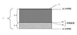
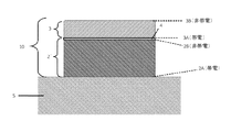
本発明の情報シートの一例として静電吸着情報シートについて図を用いて説明する。図1は、本発明を適用した静電吸着情報シートの積層構造を示す断面図である。図1に示すように静電吸着情報シート1は、不透明フィルム層2と、第一の透明フィルム層3と、を含む積層体を有している。不透明フィルム層2の一の面(面2B)上には、情報4が付与されている。図1に示すように、不透明フィルム層2は、単独の樹脂層(第1の樹脂層)のみで形成されていてもよいし、別途樹脂層上に記録層を設けて前記記録層に情報4を有する態様としてもよい。
不透明フィルム層2は、情報4を有する面2Bとは反対の面(剥離面2A)において第一の透明フィルム層3の一の面(剥離面3A)と静電気によって吸着(静電吸着)している。図1に示すように、第一の透明フィルム層3は、単独の樹脂層(第2の樹脂層)のみで形成されていてもよいし、複数の樹脂層等から構成される多層構造であってもよい。
[Layer structure]
(Electrostatic adsorption information sheet)
An electrostatic adsorption information sheet will be described with reference to the drawings as an example of the information sheet of the present invention. FIG. 1 is a cross-sectional view showing a laminated structure of an electrostatic adsorption information sheet to which the present invention is applied. As shown in FIG. 1, the electrostatic
The
図1に示すように、静電吸着情報シート1の両面(図1における面2Bおよび面3B)は非帯電となっている。静電吸着情報シート1は、使用前は外部に静電吸着力を発現しないため、特に製造過程においてロールへの貼り付きやシート同士のブロッキング等のトラブルが発生し難く、ハンドリング性が良好であり、また、多様な印刷方式に対応できる。
As shown in FIG. 1, both surfaces (
こうした静電吸着情報シート1は、第1の樹脂層および第2の樹脂層のいずれか一方の樹脂層の一の面に帯電処理を施す工程と、第2の樹脂層および第2の樹脂層を、帯電処理を施した樹脂層の帯電させた面と帯電処理を施していない樹脂層の一の面とを向い合せて積層し、互いに静電吸着させる工程と、第1の樹脂層の第2の樹脂層との吸着面とは反対の面側に情報を付与する工程とによって製造することができる。樹脂層に用いる樹脂材料および組成、帯電処理の方法、樹脂層の積層方法、情報を付与するための印刷方法については後述する。
Such an electrostatic
次に、本発明を適用した静電吸着情報シートの使用方法について説明する。図2は、本発明を適用した静電吸着情報シートの使用方法を説明するための断面図である。上述のように静電吸着情報シート1を被着体に吸着させる際には、まず図2に示すように静電吸着情報シート1から第一の透明フィルム層3を剥離する。図2に示すように、不透明フィルム層2の剥離面2Aと、第一の透明フィルム層3の剥離面3Aとは、両面ともに静電気によって帯電している。不透明フィルム層2の剥離面2Aは、情報表示体とする際に被着体に吸着させる面となる。また、第一の透明フィルム3の剥離面3Aは、不透明フィルム層2を被着体に吸着させて情報表示体とする際に、不透明フィルム層2の情報4上に吸着させる面となる。第一の透明フィルム層3は、情報シート1を情報表示体とする際に情報4を保護するための保護膜として機能させることができる。
Next, a method for using the electrostatic adsorption information sheet to which the present invention is applied will be described. FIG. 2 is a cross-sectional view for explaining a method of using the electrostatic adsorption information sheet to which the present invention is applied. When the electrostatic
(粘着情報シート)
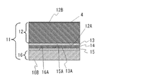
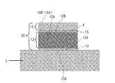
次に、本発明の情報シートの他の例として粘着情報シートについて図を用いて説明する。図3は、本発明を適用した粘着情報シートの積層構造の一例を示す断面図である。図3に示すように粘着情報シート11は、不透明フィルム層12と、第1の粘着層13と、剥離層14と、第2の粘着層15と、第一の透明フィルム層16と、を含む積層体を有している。不透明フィルム層12の一の面(面12B)上には、情報4が付与されている。
この粘着情報シート11では、不透明フィルム層12の情報4を有する面12Bとは反対の面12Aに第1の粘着層13が設けられており、第一の透明フィルム層16の不透明フィルム層12側の面16Aに第2の粘着層15が設けられている。そして、第1の粘着層13は不透明フィルム層12に接する面とは反対の面(剥離面13A)において剥離層14に粘着しており、第2の粘着層15は第一の透明フィルム層16に接する面とは反対の面(剥離面15A)において剥離層14に粘着している。これにより、不透明フィルム層12の面12Aと第一の透明フィルム層16の面16Aは、第1の粘着層13と剥離層14と第2の粘着層15を介して互いに粘着している。
図3に示すように、不透明フィルム層12は、単独の樹脂層(第1の樹脂層)のみで形成されていてもよいし、別途樹脂層上に記録層を設けて前記記録層に情報4を有する態様としてもよい。また、第一の透明フィルム層16は、単独の樹脂層(第2の樹脂層)のみで形成されていてもよいし、複数の樹脂層等から構成される多層構造であってもよい。
(Adhesive information sheet)
Next, an adhesive information sheet will be described with reference to the drawings as another example of the information sheet of the present invention. FIG. 3 is a cross-sectional view showing an example of a laminated structure of an adhesive information sheet to which the present invention is applied. As shown in FIG. 3, the
In this
As shown in FIG. 3, the
こうした粘着情報シート11は、第1の樹脂層の一の面に設けられた第1の粘着層13および第2の樹脂層の一の面に設けられた第2の粘着層15のいずれか一方の粘着層の上に、剥離層14を積層する工程と、第1の粘着層13および第2の粘着層15のうち剥離層14が積層されていない方の粘着層が設けられた樹脂層を、その粘着層の表面が剥離層に接するように剥離層の上に積層する工程と、第1の樹脂層の第1の粘着層13に接する面とは反対の面側に情報4を付与する工程とによって製造することができる。樹脂層に用いる樹脂材料および組成、粘着層13、15に用いる粘着剤および組成、樹脂層の積層方法、情報4を付与するための印刷方法については後述する。
Such an
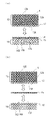
次に、図3に示す粘着情報シートの使用方法について説明する。図4は、図3に示す粘着情報シートの使用方法を説明するための断面図である。粘着情報シート11を被着体に粘着させる際には、まず図4(a)に示すように、情報シート11の第1の粘着層13から、剥離層14と第2の粘着層15と第一の透明フィルム層16からなる積層体を剥離することにより、不透明フィルム層12と第一の透明フィルム層16を分離する。分離された不透明フィルム層12の情報を有する面12Bとは反対の面12Aには第1の粘着層13が設けられている。この第1の粘着層13の剥離面13Aは、情報表示体を構成する際に、不透明フィルム層12を被着体に粘着させる面となる。次に、図4(b)に示すように、第一の透明フィルム層12に設けられた第2の粘着層15から剥離層14を剥離する。この第2の粘着層15の剥離面15Aは、情報表示体を構成する際に、第一の透明フィルム層16を不透明フィルム層12の情報4上に粘着させる面となる。第一の透明フィルム層16は、情報シート11を情報表示体とする際に情報4を保護するための保護膜として機能させることができる。
Next, a method for using the adhesive information sheet shown in FIG. 3 will be described. FIG. 4 is a cross-sectional view for explaining a method of using the adhesive information sheet shown in FIG. When the
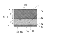
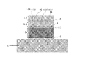
次に、本発明を適用した粘着情報シートの他の例について説明する。図5は、本発明を適用した粘着情報シートの積層構造の他の例を示す断面図である。図5に示すように情報シート17は、不透明フィルム層12と、第1の粘着層13と、第一の透明フィルム層16と、第2の粘着層15と、剥離層14と、を含む積層体を有している。不透明フィルム層12の一の面(面12B)上には、情報4が付与されている。
この粘着情報シート17では、不透明フィルム層12の情報4を有する面12Bとは反対の面12Aに第1の粘着層13が設けられている。そして、第1の粘着層13の不透明フィルム層12と接する面とは反対の面(剥離面13A)に、第一の透明フィルム層16の一の面16Aが粘着している。これにより、不透明フィルム層12の面12Aと第一の透明フィルム層16の面16Aは、第1の粘着層13を介して互いに粘着している。また、第一の透明フィルム層16の不透明フィルム層12側の面16Aとは反対の面16Bには第2の粘着層15が設けられており、第2の粘着層15の第一の透明フィルム層16に接する面とは反対の面(剥離面15A)には、剥離層14が積層されている。これにより、第2の粘着層15の剥離面15Aにゴミ等が付着するのが防止される。
図5に示すように、不透明フィルム層12は、単独の樹脂層(第1の樹脂層)のみで形成されていてもよいし、別途樹脂層上に記録層を設けて前記記録層に情報4を有する態様としてもよい。また、第一の透明フィルム層16は、単独の樹脂層(第2の樹脂層)のみで形成されていてもよいし、複数の樹脂層等から構成される多層構造であってもよい。
Next, another example of the adhesive information sheet to which the present invention is applied will be described. FIG. 5 is a cross-sectional view showing another example of a laminated structure of an adhesive information sheet to which the present invention is applied. As shown in FIG. 5, the
In the
As shown in FIG. 5, the
こうした粘着情報シート17は、第1の樹脂層の一の面に設けられた第1の粘着層13の上に、一の面に第2の粘着層15が設けられた第2の樹脂層を、その第2の粘着層15が設けられた面とは反対の面が第1の粘着層13に接するように積層する工程と、第2の粘着層15の第2の樹脂層に接する面とは反対の面に剥離層14を積層する工程と、第1の樹脂層の第1の粘着層13が設けられた面とは反対の面側に情報4を付与する工程とによって製造することができる。樹脂層に用いる樹脂材料および組成、粘着層13、15に用いる粘着剤および組成、樹脂層の積層方法、情報4を付与するための印刷方法については後述する。
Such an
図5に示す粘着情報シート17の使用方法について説明する。図6は、図5に示す粘着情報シート17の使用方法を説明するための断面図である。この粘着情報シート17を被着体に粘着させる際には、まず図6(a)に示すように、粘着情報シート17の第1の粘着層13から第一の透明フィルム層16と第2の粘着層15と剥離層14からなる積層体を剥離することにより、不透明フィルム層12と第一の透明フィルム層16とを分離する。分離された不透明フィルム層12の情報を有する面12Bとは反対の面12Aには第1の粘着層13が設けられている。この第1の粘着層13の剥離面13Aは、情報表示体を構成する際に、不透明フィルム層12を被着体に粘着させる面となる。次に、図6(b)に示すように、第一の透明フィルム層16に設けられた第2の粘着層15から剥離層14を剥離する。この第2の粘着層15の剥離面15Aは、情報表示体を構成する際に、第一の透明フィルム層16を不透明フィルム層12の情報4上に粘着させる面となる。第一の透明フィルム層16は、情報シート17を情報表示体とする際に情報4を保護するための保護膜として機能させることができる。
A method for using the
(負圧吸着情報シート)
次に、本発明の情報シートのさらに他の例として負圧吸着情報シートについて説明する。負圧吸着情報シートの積層構造としては、第1の粘着層13の代わりに第1の吸着層が不透明フィルム層12に設けられ、第2の粘着層13の代わりに第2の吸着層が第一の透明フィルム層16に設けられ、これら吸着層と、これら吸着層に接する層とが負圧により吸着していること以外は、上記の粘着情報シート11、17と同様の積層構造を採用することができる。また、その製造方法および使用方法についても、第1の粘着層13および第2の粘着層15が第1の吸着層および第2の吸着層であり、粘着の代わりに負圧による吸着であること以外は、上記の粘着情報シート11、17の製造方法および使用方法と同様であり、これらについての説明を参照することができる。
負圧を発現する吸着層としては多孔質層を用いることができる。例えば、多孔質層に、第一の透明フィルム層や剥離層、樹脂フィルム層、被着体等を圧接させると、多孔質層の各孔部内の空気が一部排気されて各孔部内が負圧状態になる。これにより、これらの物が多孔質層に負圧により吸着される。多孔質層の材料や組成については、後述する。
以上のような、本発明の情報シートは、壁面、ガラス面、柱、掲示板、ロッカー、書棚等の被着体に吸着させて情報表示体とする前の態様であり、例えば、出荷時、搬送時、販売時等に好適な態様である。
(Negative pressure adsorption information sheet)
Next, a negative pressure adsorption information sheet will be described as still another example of the information sheet of the present invention. In the laminated structure of the negative pressure adsorption information sheet, the first adsorption layer is provided on the
A porous layer can be used as the adsorption layer that develops a negative pressure. For example, when the first transparent film layer, the release layer, the resin film layer, the adherend, or the like is pressed against the porous layer, a part of the air in each hole of the porous layer is exhausted and the inside of each hole is negative. Pressure state. Thereby, these things are adsorbed to the porous layer by negative pressure. The material and composition of the porous layer will be described later.
The information sheet of the present invention as described above is a mode before adsorbing to an adherend such as a wall surface, a glass surface, a pillar, a bulletin board, a locker, a book shelf, etc. to form an information display body. This is a mode suitable for time and sales.
(情報表示体)
本発明の情報表示体の一例について説明する。図7は、本発明の情報表示体の積層構造例を示す断面図である。図7において図1および図2と共通する部材については同様の符号を付しその説明を省略する。図7に示すように、情報表示体は、樹脂フィルム層2’と第一の透明フィルム層3とを含む積層体10が被着体5上に静電吸着した構造を有している。樹脂フィルム層2’は第1の樹脂層を含むものであり、樹脂フィルム層2’の一の面(面2B)には情報4が付与されている。そして、樹脂フィルム層2’の情報4を有する面(面2B)上に、第一の透明フィルム層3の剥離面3Aが静電吸着している。本発明の情報表示体における樹脂フィルム層2は、透明であっても不透明であってもよく、本発明の情報シートにおける不透明フィルム層を含む概念である。このため、樹脂フィルム層2’を構成する第1の樹脂層は、不透明フィルム層を構成する第1の樹脂層と同じであってもよい。
(Information display)
An example of the information display body of the present invention will be described. FIG. 7 is a cross-sectional view showing an example of a laminated structure of the information display body of the present invention. In FIG. 7, members that are the same as those in FIG. 1 and FIG. As shown in FIG. 7, the information display body has a structure in which a laminate 10 including a
このため、図7の情報表示体は、例えば、上述のように第一の透明フィルム層3を不透明フィルム層2から剥離した後、静電気によって帯電している不透明フィルム層2の剥離面2Aを被着体5に吸着させ、更に、静電気によって帯電している第一の透明フィルム層3の剥離面3Aを不透明フィルム層2の情報4上に吸着させることによって作製することができる。情報4は、面3B側より観察することで第一の透明フィルム層3を介して視認することができる。図7の情報表示体では、情報4が第一の透明フィルム層3によって保護されている。また、積層体10は静電気によって被着体5に吸着しているため、情報表示体としての役割を果たした後に被着体5から剥がして回収する際に、被着体5側に糊が残ってしまったり、表面の塗装が剥れたりすることなく、容易に剥離させることができる。また、積層体10の最外面である第一の透明フィルム層3の面3Bは静電気によって帯電させていないため、静電気によるゴミ等の付着を抑制することができる。
For this reason, the information display body of FIG. 7 covers the
本発明の情報表示体の他の例について説明する。図8は、本発明の情報表示体の積層構造の他の例を示す断面図である。図8において図3〜図6と共通する部材については同様の符号を付しその説明を省略する。
図8に示すように、情報表示体は、第1の粘着層13と、樹脂フィルム層12’と、第2の粘着層15と、第一の透明フィルム層3とを含む積層体20が被着体5上に粘着した構造を有している。樹脂フィルム層12’は第1の樹脂層を含むものであり、樹脂フィルム層12’の一の面(面12B)には情報4が付与されている。そして、樹脂フィルム層12’の情報4を有する面(面12B)上に、第一の透明フィルム層16の一の面16A(または16B)が第2の粘着層15を介して粘着している。本発明の情報表示体における樹脂フィルム層12’は、透明であっても不透明であってもよく、本発明の情報シートにおける不透明フィルム層を含む概念である。このため、樹脂フィルム層12’を構成する第1の樹脂層は、不透明フィルム層を構成する第1の樹脂層と同じであってもよい。
Another example of the information display body of the present invention will be described. FIG. 8 is a cross-sectional view showing another example of the laminated structure of the information display body of the present invention. In FIG. 8, members that are the same as those in FIGS.
As shown in FIG. 8, the information display body includes a laminate 20 including a first
こうした情報表示体は、例えば、図3および図5に示す本発明の情報シート(粘着情報シート)11、17を用いることにより製造することができる。
情報表示体を製造するには、まず粘着情報シート11、17の第1の粘着層13から、剥離層14と第2の粘着層15と第一の透明フィルム層16からなる積層体を剥離することにより、不透明フィルム層12と第一の透明フィルム層16を分離した後、不透明フィルム層12に設けられた第1の粘着層13の剥離面13Aを被着体5に粘着させる。更に、第一の透明フィルム層16に設けられた第2の粘着層15から剥離層14を剥離し、その第2の粘着層15の剥離面15Aを不透明フィルム層12の情報4上に粘着させることによって作製することができる。ここで、情報シートとして図3に示す粘着情報シート11を用いた場合には、第一の透明フィルム層16の各面16A、16Bのうち、粘着情報シート11において、不透明フィルム層12側とは反対側にあった面16Bが情報表示体の外側の面(樹脂フィルム側の面とは反対の面)を構成する態様になる。また、情報シートとして図5に示す粘着情報シート17を用いた場合には、第一の透明フィルム層16の各面16A、16Bのうち、粘着情報シート17において、不透明フィルム層12側にあった面16Aが情報表示体の外側の表面(樹脂フィルム層12’側の面とは反対の面)を構成する態様になる。
情報4は、第一の透明フィルム層16の樹脂フィルム層12’側の面とは反対の面16B(または16A)側より観察することで、第一の透明フィルム層16を介して視認することができる。図6の情報表示体では、情報4が第一の透明フィルム層16によって保護されている。
Such an information display body can be manufactured by using, for example, the information sheets (adhesive information sheets) 11 and 17 of the present invention shown in FIGS.
In order to manufacture the information display body, first, the laminate composed of the
The
また、本発明の情報表示体は、図8に示す情報表示体において、第1の粘着層13の代わりに第1の吸着層が設けられ、第2の粘着層15の代わりに第2の吸着層が設けられており、各吸着層が発現する負圧により、第1の吸着層が被着体が吸着し、第2の吸着層が不透明フィルム層の情報上に吸着している情報表示体であってもよい。こうした情報表示体は、図3または図5に示す粘着情報シートにおいて、第1の粘着層13の代わりに第1の吸着層が設けられ、第2の粘着層15の代わりに第2の吸着層が設けられた負圧情報シートを用い、図3または図5に示す粘着情報シートを用いる場合と同様の工程により製造することができる。こうした情報表示体では、積層体が負圧によって被着体に吸着しているため、情報表示体としての役割を果たした後に被着体から剥がして回収する際に、被着体側に糊が残ってしまったり、表面の塗装が剥れたりすることなく、容易に剥離させることができる。
Further, the information display body of the present invention is the information display body shown in FIG. 8, in which a first adsorption layer is provided instead of the first
本発明の情報表示体の製造方法は、上記に説明した方法に限定されるものではなく、同様の構造を有するものであれば特に製造方法は限定されるものではない。例えば、本発明の情報表示体は、本発明の情報シート以外の情報シートと透明フィルム層を有する透明貼着シートを用いることで製造してもよいし、本発明の情報シートと、本発明の情報シート以外の情報シートや透明貼着シートを組み合わせて製造してもよい。
本発明の情報シート以外の情報シートとしては、樹脂層を含み、一の面に情報を有するとともに他の面が吸着または粘着を発現する吸着面または粘着面となるように構成された樹脂フィルム層と、樹脂フィルム層の吸着面または粘着面に積層された剥離層とを含む情報シートを挙げることができる。樹脂フィルム層は、透明であっても不透明であってもよい。また、透明貼着シートとしては、樹脂層を含み、一の面が吸着または粘着を発現する吸着面または粘着面となるように構成された透明フィルム層と、透明フィルム層の吸着面または粘着面に積層された剥離層とを含む透明貼着シートを挙げることができる。
ここで、本発明の情報シート以外の情報シートおよび透明貼着シートにおける「吸着」および「粘着」の定義と具体例については、本発明における「吸着」および「粘着」の定義と具体例についての説明を参照することができる。
The manufacturing method of the information display body of this invention is not limited to the method demonstrated above, A manufacturing method will not be specifically limited if it has the same structure. For example, the information display body of the present invention may be manufactured by using an information sheet other than the information sheet of the present invention and a transparent adhesive sheet having a transparent film layer, or the information sheet of the present invention and the present invention. You may manufacture combining information sheets other than an information sheet, and a transparent sticking sheet.
As an information sheet other than the information sheet of the present invention, a resin film layer including a resin layer and having information on one surface and the other surface serving as an adsorption surface or an adhesion surface that exhibits adsorption or adhesion And an information sheet including a release layer laminated on the adsorption surface or the adhesive surface of the resin film layer. The resin film layer may be transparent or opaque. Further, as the transparent adhesive sheet, a transparent film layer including a resin layer and configured so that one surface becomes an adsorption surface or an adhesion surface that expresses adsorption or adhesion, and an adsorption surface or an adhesion surface of the transparent film layer And a transparent adhesive sheet including a release layer laminated on the substrate.
Here, for definitions and specific examples of “adsorption” and “adhesion” in information sheets other than the information sheet of the present invention and transparent adhesive sheets, and specific examples of “adsorption” and “adhesion” in the present invention You can refer to the description.
本発明の情報シート以外の情報シートと透明貼着シートを用いて情報表示体を製造するには、情報シートの樹脂フィルム層から剥離層を剥離した後、露出した吸着面または粘着面を被着体5に吸着または粘着させる。更に透明貼着シートの透明フィルム層から剥離層を剥離した後、露出した吸着面または粘着面を樹脂フィルム層の情報上に吸着または粘着させることによって情報表示体を製造することができる。
In order to produce an information display body using an information sheet other than the information sheet of the present invention and a transparent adhesive sheet, after peeling the release layer from the resin film layer of the information sheet, the exposed adsorption surface or adhesive surface is attached. Adsorbed or adhered to the
また、本発明の情報シートと、本発明の情報シート以外の情報シートを用いて情報表示体を製造するには、本発明の情報シート以外の情報シートの樹脂フィルム層から剥離層を剥離した後、露出した吸着面または粘着面を被着体5に吸着または粘着させる。更に本発明の情報シートから上記の手順で第一の透明フィルム層、もしくは第2の吸着層または第2の粘着層が設けられた第一の透明フィルム層を分離して吸着面または粘着面を露出させた後、その吸着面または粘着面を樹脂フィルム層の情報上に吸着または粘着させることによって情報表示体を製造することができる。
Moreover, in order to manufacture an information display body using the information sheet of the present invention and the information sheet other than the information sheet of the present invention, after peeling the release layer from the resin film layer of the information sheet other than the information sheet of the present invention The exposed adsorption surface or adhesive surface is adsorbed or adhered to the
また、本発明の情報シートと、本発明の情報シート以外の透明貼着シートを用いて情報表示体を製造するには、本発明の情報シートから上記の手順で不透明フィルム層、もしくは第1の吸着層または第1の粘着層が設けられた不透明フィルム層を分離し、吸着面または粘着面を露出させた後、その吸着面または粘着面を被着体5に吸着または粘着させる。更に透明貼着シートの透明フィルム層から剥離層を剥離した後、露出した吸着面または粘着面を不透明フィルム層の情報上に吸着または粘着させることによって情報表示体を製造することができる。
Moreover, in order to manufacture an information display body using the information sheet of the present invention and the transparent adhesive sheet other than the information sheet of the present invention, the opaque film layer or the first step is performed from the information sheet of the present invention by the above procedure. After separating the opaque film layer provided with the adsorption layer or the first adhesive layer and exposing the adsorption surface or the adhesion surface, the adsorption surface or adhesion surface is adsorbed or adhered to the
もっとも、本発明の情報シート以外の情報シートや透明貼着シートを用いる場合、1つの情報表示体を製造する毎に、2枚の剥離層が手元に残るのに対して、本発明の情報シートを用いれば、手元に残る剥離層が1枚で済む。このため、本発明の情報シートによれば、剥離体の回収や運搬して処理する手間を軽減することができ、無駄になる資材を削減することができるという効果を得ることができる。 However, when an information sheet other than the information sheet of the present invention or a transparent adhesive sheet is used, every time one information display is manufactured, two release layers remain at hand, whereas the information sheet of the present invention. Is used, only one release layer remains at hand. For this reason, according to the information sheet of this invention, the effort which can collect | recover a peeling body, convey, and process it can be reduced, and the effect that the material which becomes useless can be reduced can be acquired.
また、図7および図8においては、第一の透明フィルム層3、16を一層のみ使用した態様について説明したが、本発明は前記態様に限定されることなく、図9および図10に示すように、第一の透明フィルム層3、16の樹脂フィルム層側の面とは反対の面3B、16B(または16A)側に他の透明フィルム層6を有していてもよい。図9および図10において、他の透明フィルム層6の面4Aと第一の透明フィルム層3、16の面3B、16B(または16A)とは静電吸着をしていてもよいし、静電吸着以外の吸着をしていてもよいし、粘着または接着をしていてもよい。また、他の透明フィルム層6の第一の透明フィルム層3、16側ではない面(面4B)には第二の付加情報が付加されていてもよい。他の透明フィルム層6の面4Bには、1層以上のさらに他の透明フィルム層を同様に積層することが可能である。このとき積層する各透明フィルム層には、それぞれ付加情報が付加されていてもよい。
前記他の透明フィルム層は、単独で用意した片面を静電気によって帯電させた透明フィルムや片面に吸着層または粘着層18が設けられた透明フィルムであってもよいし、貼着シートから剥離した透明フィルム層であってもよい。貼着シートから剥離した透明フィルム層として、第3の樹脂層を含み、一の面に第二の付加情報を付加することができる第二の透明フィルム層と、第4の樹脂層を含み且つ前記透明フィルム層の前記第二の付加情報を付加することができる前記一の面とは反対の面に吸着または粘着した第二の樹脂フィルム層と、を含む貼着シートから剥離した前記第二の透明フィルム層を例示することができる。
7 and 8, the embodiment in which only the first
The other transparent film layer may be a transparent film in which one side prepared alone is charged by static electricity or a transparent film in which an adsorption layer or an adhesive layer 18 is provided on one side, or a transparent film peeled off from an adhesive sheet. It may be a film layer. As a transparent film layer peeled from the sticking sheet, it includes a third resin layer, a second transparent film layer capable of adding second additional information to one surface, and a fourth resin layer, and The second resin film peeled from the adhesive sheet, which includes the second resin film layer adsorbed or adhered to the surface opposite to the one surface to which the second additional information of the transparent film layer can be added. The transparent film layer can be exemplified.
[付加情報]
(第一の付加情報)
図7および図8における情報表示体は、第一の透明フィルム層3、16の樹脂フィルム層2’、12’(不透明フィルム層2、12)側の面とは反対の面に第一の付加情報を有していてもよい。前記第一の付加情報は、図7および図8における情報表示体を形成した後に、面3B、16B(または16A)上に付与してもよいし、図1および図3における情報シート1、11の状態で、不透明フィルム層2、12側の面(面3B、面16B)上に付加しておいてもよい。また、図5における情報シート17の状態で、不透明フィルム層12側の面とは反対の面(面16A)上に付加しておいてもよい。また、前記付加情報は、前記情報と重ね合わせた際に一群の情報となることが好ましい。第一の透明フィルム層3、16への付加情報の付与は後述する印刷、マーカー、ラベル、付箋紙等を用いて行うことができる。
[Additional information]
(First additional information)
7 and FIG. 8, the first display is applied to the surface of the first
前記第一の付加情報について図11を用いて説明する。ここでは、情報シートが図1に示す静電吸着情報シートであり、情報表示体が図7に示す情報表示体である場合を例にして説明するが、本発明の他の情報シート(例えば、図3および図5に示す粘着情報シートや負圧吸着情報シート等)や本発明の他の情報表示体についても、同様の手法により同様の情報および付加情報を付与することができる。
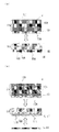
図11は、本発明における情報と第一の付加情報との関係を示す説明図である。ここで、図11(A)は、第一の付加情報を有する情報シート1を面3B側から観察した説明図であり、図11(B)は、情報シート1を面2B側から観察した説明図である。更に、図11(C)は、第一の付加情報を有する積層体10を有する情報表示体を面3B側から観察した説明図である。図11(A)、(B)に示すように、情報シート1は、第一の透明フィルム層の不透明フィルム層との吸着面とは反対の面3B上に第一の付加情報7(八分音符)が付与されており、不透明フィルム層の一の面2B上に情報4(五線譜)が付与されている。
The first additional information will be described with reference to FIG. Here, the case where the information sheet is the electrostatic adsorption information sheet shown in FIG. 1 and the information display body is the information display body shown in FIG. 7 will be described as an example, but other information sheets of the present invention (for example, Similar information and additional information can be applied to the other information display bodies of the present invention and the adhesive information sheets and negative pressure adsorption information sheets shown in FIGS. 3 and 5 by the same method.
FIG. 11 is an explanatory diagram showing the relationship between the information and the first additional information in the present invention. Here, FIG. 11A is an explanatory diagram in which the
図11において、第一の付加情報7は、情報と重ね合わせた際に一群の情報となるように設計されている。図11(B)に示すように、情報シート1の不透明フィルム層の面2B上には、情報4が形成されている。情報シート1から不透明フィルム層を剥離し被着体に吸着させ、剥離した第一の透明フィルム層を不透明フィルム層に形成された情報上に吸着させて図7における積層体10を形成すると、図11(C)に示すように、積層体10の第一の透明フィルム層は、樹脂フィルム層(不透明フィルム層)との吸着面とは反対の面3Bに第一の付加情報7を有することとなる。積層体10を形成した場合、面3B側から第一の透明フィルム層を介して情報4を観察すると、情報4に重ねて積層体10の面3B上に形成された第一の付加情報7が表示されることとなる。図11(C)に示すように第一の付加情報7は情報4と重ね合わせた際に一群の情報8として表示される。例えば、共通の情報4を使用しつつ、第一の付加情報7を変更することで積層体10の設置者、位置、設置時期等の状況に合わせた情報表示体とすることができる。
剥離した第一の透明フィルム層を不透明フィルム層の情報上に重ねる態様は特に制限されない。例えば図1や図3に示す情報シート1、11では、剥離した第一の透明フィルム層は裏返して不透明フィルム層に重ねることになるが、裏返す際には任意の軸を中心に180°回転させることができる。例えば、剥離した第一の透明フィルム層が長辺と短辺を有する場合は、その長辺を軸として180°回転させた状態にしてもよいし、短辺を軸として180°回転させた状態にしてもよい。また、剥離した第一の透明フィルム層に存在する対称軸を軸として180°回転させた状態にしてもよい。一方、図5に示す情報シート17では、剥離した第一の透明フィルム層は裏返さずに不透明フィルム層に重ねることになるが、重ねる際には、不透明フィルムに対する向きを変えずに重ねてもよいし、面内で180°回転させた状態にしてもよいし、面内で90°回転させた状態にしてもよい。第一の付加情報が使用時において非可変情報である場合、いずれかの態様で回転することを予め決めておいて、重ねたときに一群の情報が表示されるように、情報と第一の付加情報を相互に関連づけて付与しておくことが好ましい。ここで「第一の付加情報が使用時において非可変情報である場合」には、情報シート1を用いて情報表示体を作製して表示させるまでの間に第一の付加情報を変更することができない場合と、第一の付加情報を変更することが可能であっても変更しない場合が含まれる。付加情報の変更には、情報の付加と削除と改変が含まれる。また、第一の付加情報が使用時において可変情報である場合、重ねたときに一群の情報が表示されるように、マーカー、ラベル、付箋紙等の方法を用いて変更可能な情報を付与することが好ましい。
In FIG. 11, the first additional information 7 is designed to be a group of information when superimposed on the information. As shown in FIG. 11B,
The aspect in which the peeled first transparent film layer is superimposed on the information of the opaque film layer is not particularly limited. For example, in the
本発明の情報表示体における樹脂フィルム層と被着体は、それぞれ透明の材料で構成してもよい。そうすることによって、情報4や第一の付加情報7を情報表示体の奥にある背景とともに視認することができるようになる。また、情報表示体の情報4や第一の付加情報7を、積層体10側からだけでなく、被着体5側からも視認することができるようになる。例えば、透明ガラス製や透明樹脂製のウィンドウを被着体として選択し、ウィンドウの内側に積層体10を形成すれば、ウィンドウの内側と外側の両方から情報4と第一の付加情報7を視認することができる。情報表示体を被着体5側から見せることを意図する場合は、情報4が第一の付加情報7の前面に表示されることになるため、第一の付加情報7を調整することによって情報の背景を変えやすくなる。
本発明における情報と第一の付加情報の組み合わせは、重ね合わせることにより一群の情報となるものであれば、特に制限されない。例えば、下記表1に情報と第一の付加情報の組合せの具体例を挙げる。
The resin film layer and the adherend in the information display body of the present invention may each be made of a transparent material. By doing so, it becomes possible to visually recognize the
The combination of the information and the first additional information in the present invention is not particularly limited as long as it becomes a group of information by being superimposed. For example, Table 1 below gives specific examples of combinations of information and first additional information.

(第二および第三の付加情報)
本発明において、樹脂フィルム層の一の面に有する情報の上に第一の付加情報を重ねて得られた情報表示体の第一の付加情報の上に、さらに第二の付加情報を重ねることができる。加えて、第二の付加情報の上にさらに第三の付加情報を重ねることができる。
第3の樹脂層を含み、一の面に第二の付加情報を付加することができる第二の透明フィルム層と、第4の樹脂層を含み且つ前記透明フィルム層の前記第二の付加情報を付加することができる前記一の面とは反対の面に吸着または粘着した第二の樹脂フィルム層とを含む貼着シートを準備し、該貼着シートから前記第二の透明フィルム層を剥がすことによって、前記第二の付加情報を有する第二の透明フィルム層を得ることができる。こうして得た第二の透明フィルム層を、樹脂フィルム層の一の面に有する情報の上に第一の付加情報を重ねて得られた積層体の第一の付加情報の上にさらに積層することにより、情報と第一の付加情報と第二の付加情報を重ねた情報表示体を得ることができる。
また、前記貼着シートの前記第二の樹脂フィルム層が第三の透明フィルム層である場合には、該貼着シートから前記第二の透明フィルム層を剥がして残った第三の透明フィルム層として前記第三の付加情報を得ることができる。こうして得た第三の付加情報を有する第三の透明フィルム層を、情報の上に第一の付加情報と第二の付加情報を重ねて得られた積層体の第二の付加情報の上にさらに積層することにより、情報と第一の付加情報と第二の付加情報と第三の付加情報を重ねた情報表示体を得ることができる。
ここで、前記第二の付加情報および第三の付加情報の内容は例えば前記第一の付加情報で列記されているものの中から選択できるが、前記第一の付加情報と同じである必要はない。
第二の付加情報または第三の付加情報が使用時において非可変情報である場合、重ねたときに一群の情報が表示されるように、情報と第二の付加情報または第三の付加情報を相互に関連づけて付与しておくことが好ましい。
また、前記第二の付加情報または第三の付加情報は変更可能な情報であってもよい。
以下において、本発明の情報シートに用いられる各部材について説明する。
(Second and third additional information)
In the present invention, the second additional information is further superimposed on the first additional information of the information display body obtained by superimposing the first additional information on the information on one surface of the resin film layer. Can do. In addition, the third additional information can be further superimposed on the second additional information.
A second transparent film layer including a third resin layer and capable of adding second additional information on one surface; and a second transparent information including the fourth resin layer and the transparent film layer. An adhesive sheet including a second resin film layer adsorbed or adhered to the surface opposite to the one surface to which the first transparent film layer can be added is prepared, and the second transparent film layer is peeled off from the adhesive sheet Thus, a second transparent film layer having the second additional information can be obtained. The second transparent film layer thus obtained is further laminated on the first additional information of the laminate obtained by superimposing the first additional information on the information on one surface of the resin film layer. Thus, an information display body in which the information, the first additional information, and the second additional information are overlaid can be obtained.
In addition, when the second resin film layer of the adhesive sheet is a third transparent film layer, the third transparent film layer remaining by peeling off the second transparent film layer from the adhesive sheet As a result, the third additional information can be obtained. The third transparent film layer having the third additional information thus obtained is placed on the second additional information of the laminate obtained by superimposing the first additional information and the second additional information on the information. Further, by stacking, an information display body in which information, first additional information, second additional information, and third additional information are superimposed can be obtained.
Here, the contents of the second additional information and the third additional information can be selected from, for example, those listed in the first additional information, but need not be the same as the first additional information. .
When the second additional information or the third additional information is non-variable information at the time of use, the information and the second additional information or the third additional information are displayed so that a group of information is displayed when superimposed. It is preferable to give them in association with each other.
The second additional information or the third additional information may be changeable information.
Below, each member used for the information sheet of this invention is demonstrated.
[不透明フィルム層]
本発明の情報シートを構成する不透明フィルム層は、第1の樹脂層を含み且つ一の面に情報を有する。本発明において不透明フィルム層とは、不透明度が50〜100%の層を意味する。不透明度が50%以上であれば、ラベルとして使用した際に、被着対象物の着色や絵柄・模様が透けて見えることがないという利点がある。前記不透明フィルム層の不透明度は、好ましく60〜100%であり、より好ましくは70〜100%である。本発明における不透明度は、JIS−P−8138に準拠し、測定背面に、黒色および白色標準板を当て、光の反射率の比(黒色板/白色板)を百分率で示した値で表示される。
尚、本発明の情報表示体の樹脂フィルム層も、本発明の情報シートにおける不透明フィルム層と同様の構成とすることができる。但し、本発明の情報表示体における樹脂フィルム層は、不透明度が50〜100%であるものに限定されるものではなく、不透明度が50%未満であってもよい。即ち、本発明の情報表示体における樹脂フィルム層に用いられる樹脂としては、第1の樹脂の同様の樹脂や後述する透明フィルム層に用いられる第2の樹脂と同様の樹脂を用いることができる。
[Opaque film layer]
The opaque film layer constituting the information sheet of the present invention includes the first resin layer and has information on one surface. In the present invention, the opaque film layer means a layer having an opacity of 50 to 100%. When the opacity is 50% or more, there is an advantage that the coloring of the adherend and the pattern / pattern are not seen through when used as a label. The opacity of the opaque film layer is preferably 60 to 100%, more preferably 70 to 100%. The opacity in the present invention is displayed in accordance with JIS-P-8138, with a black and white standard plate applied to the measurement back surface, and the light reflectance ratio (black plate / white plate) expressed as a percentage. The
In addition, the resin film layer of the information display body of this invention can also be set as the structure similar to the opaque film layer in the information sheet of this invention. However, the resin film layer in the information display body of the present invention is not limited to one having an opacity of 50 to 100%, and the opacity may be less than 50%. That is, as the resin used for the resin film layer in the information display body of the present invention, the same resin as the first resin or the same resin as the second resin used for the transparent film layer described later can be used.
不透明フィルム層は、種々の被着体に貼り付け表示することが可能である。例えば、不透明フィルム層が静電吸着力により被着体に貼り付けられるものである場合、情報表示体として使用する際に静電吸着力が高く、静電吸着力の持続性も充分で長期に亘り表示使用することができ、静電吸着力が湿度に影響され難く、且つ使用後は被着体を汚さずに容易に剥がすことができることが好ましい。上述のように不透明フィルム層はその片面に記録層を備えることができる。 The opaque film layer can be pasted and displayed on various adherends. For example, when an opaque film layer is affixed to an adherend by electrostatic attraction, the electrostatic attraction is high when used as an information display, and the sustainability of the electrostatic attraction is long enough. It is preferable that the display can be used for a long time, the electrostatic attraction force is hardly affected by humidity, and can be easily peeled off after use without contaminating the adherend. As described above, the opaque film layer can have a recording layer on one side.
不透明フィルム層の厚みは20〜500μmであることが好ましく、25〜400μmであることがより好ましく、30〜200μmであることが更に好ましく、40〜150μmであることが特に好ましい。不透明フィルム層の厚みが20μm以上であると、不透明フィルム層を被着体に貼り付ける際にシワが入りづらく、上手く貼り付けやすい。また、不透明フィルム層の厚みが500μm以下であると不透明フィルム層の自重が大きくなりすぎず、静電吸着力やその他の吸着力、粘着力で自重を保持できずに被着体から落下してしまうのを防止することができる。 The thickness of the opaque film layer is preferably 20 to 500 μm, more preferably 25 to 400 μm, still more preferably 30 to 200 μm, and particularly preferably 40 to 150 μm. When the thickness of the opaque film layer is 20 μm or more, wrinkles are not easily formed when the opaque film layer is applied to the adherend, and it is easy to apply it well. Also, if the thickness of the opaque film layer is 500 μm or less, the weight of the opaque film layer does not become too large, and the weight of the opaque film layer falls from the adherend without being able to hold its own weight due to electrostatic adsorption force, other adsorption force, or adhesive force. Can be prevented.
[第1の樹脂層]
本発明における第1の樹脂層は、不透明フィルム層を構成するものである。不透明フィルム層が静電吸着力により被着体に貼り付けられるものである場合、第1の樹脂層は、さらに帯電処理を施すことによって内部に電荷を保持し、その静電吸着力によって不透明フィルム層を表示物として被着体に貼り付けることを可能にするものである。
本発明の第1の樹脂層は熱可塑性樹脂を含むことが好ましい。特に、静電吸着力により貼り付けられる不透明フィルム層の第1の樹脂層として、絶縁性の優れた熱可塑性樹脂を使用することにより、内部に蓄積した電荷を保持しやすく好ましい。
[First resin layer]
The first resin layer in the present invention constitutes an opaque film layer. When the opaque film layer is affixed to the adherend by electrostatic attraction force, the first resin layer retains electric charge therein by further charging, and the opaque film layer by the electrostatic attraction force. The layer can be attached to the adherend as a display object.
It is preferable that the 1st resin layer of this invention contains a thermoplastic resin. In particular, it is preferable to use a thermoplastic resin having an excellent insulating property as the first resin layer of the opaque film layer to be attached by electrostatic attraction, so that the charges accumulated therein can be easily retained.
第1の樹脂層に用いる熱可塑性樹脂の種類は特に制限されず、以下において例示する樹脂を適宜用いることができる。これらの樹脂は、特に静電吸着力により貼り付けられる不透明フィルム層の第1の樹脂層に好適に用いることができる。具体的には、第1の樹脂層の樹脂として、高密度ポリエチレン、中密度ポリエチレン、低密度ポリエチレン、プロピレン系樹脂、ポリメチル−1−ペンテン等のポリオレフィン系樹脂、エチレン・酢酸ビニル共重合体、エチレン・アクリル酸共重合体、マレイン酸変性ポリエチレン、マレイン酸変性ポリプロピレン等の官能基含有ポリオレフィン系樹脂、ナイロン−6、ナイロン−6,6等のポリアミド系樹脂、ポリエチレンテレフタレートやその共重合体、ポリブチレンテレフタレート、脂肪族ポリエステル等の熱可塑性ポリエステル系樹脂、ポリカーボネート、アタクティックポリスチレン、シンジオタクティックポリスチレン等を使用することができる。これらの熱可塑性樹脂の中では、絶縁性と加工性に優れるポリオレフィン系樹脂、官能基含有ポリオレフィン系樹脂を用いることが好ましい。
ポリオレフィン系樹脂のより具体的な例としては、エチレン、プロピレン、ブチレン、ヘキセン、ブタジエン、イソプレン、クロロプレン、メチル−1−ペンテンなどのオレフィン類の単独重合体、及び、これらオレフィン類2種類以上からなる共重合体が挙げられる。
The type of the thermoplastic resin used for the first resin layer is not particularly limited, and the resins exemplified below can be used as appropriate. These resins can be suitably used for the first resin layer of the opaque film layer that is attached by electrostatic adsorption force. Specifically, as the resin of the first resin layer, high density polyethylene, medium density polyethylene, low density polyethylene, propylene resin, polyolefin resin such as polymethyl-1-pentene, ethylene / vinyl acetate copolymer, ethylene -Functional group-containing polyolefin resins such as acrylic acid copolymer, maleic acid-modified polyethylene and maleic acid-modified polypropylene, polyamide resins such as nylon-6 and nylon-6,6, polyethylene terephthalate and copolymers thereof, polybutylene Thermoplastic polyester resins such as terephthalate and aliphatic polyester, polycarbonate, atactic polystyrene, syndiotactic polystyrene and the like can be used. Among these thermoplastic resins, it is preferable to use a polyolefin resin and a functional group-containing polyolefin resin excellent in insulation and processability.
More specific examples of polyolefin resins include homopolymers of olefins such as ethylene, propylene, butylene, hexene, butadiene, isoprene, chloroprene, methyl-1-pentene, and two or more of these olefins. A copolymer is mentioned.
官能基含有ポリオレフィン系樹脂のより具体的な例としては、前記オレフィン類と共重合可能な官能基含有モノマーとの共重合体が挙げられる。かかる官能基含有モノマーとしては、スチレン、α−メチルスチレンなどのスチレン類、酢酸ビニル、ビニルアルコール、プロピオン酸ビニル、酪酸ビニル、ピバリン酸ビニル、カプロン酸ビニル、ラウリン酸ビニル、ステアリン酸ビニル、安息香酸ビニル、ブチル安息香酸ビニル、シクロヘキサンカルボン酸ビニルなどのカルボン酸ビニルエステル類、アクリル酸、メタクリル酸、メチル(メタ)アクリレート、エチル(メタ)アクリレート、ブチル(メタ)アクリレート、ヘキシル(メタ)アクリレート、オクチル(メタ)アクリレート、2−エチルヘキシル(メタ)アクリレート、ステアリル(メタ)アクリレート、ベンジル(メタ)アクリレート、シクロヘキシル(メタ)アクリレート、イソボニル(メタ)アクリレート、ジシクロペンタニル(メタ)アクリレート、(メタ)アクリルアミド、N−メタロール(メタ)アクリルアミドなどの(メタ)アクリル酸エステル類、メチルビニルエーテル、エチルビニルエーテル、プロピルビニルエーテル、ブチルビニルエーテル、シクロペンチルビニルエーテル、シクロヘキシルビニルエーテル、ベンジルビニルエーテル、フェニルビニルエーテルなどのビニルエーテル類が特に代表的である。これら官能基含有モノマーの中から必要に応じ1種類もしくは2種類以上を適宜選択し共重合したものを用いることができる。
更にこれらポリオレフィン系樹脂及び官能基含有ポリオレフィン系樹脂を必要によりグラフト変性し使用することも可能である。
More specific examples of functional group-containing polyolefin resins include copolymers with functional group-containing monomers copolymerizable with the olefins. Examples of such functional group-containing monomers include styrenes such as styrene and α-methylstyrene, vinyl acetate, vinyl alcohol, vinyl propionate, vinyl butyrate, vinyl pivalate, vinyl caproate, vinyl laurate, vinyl stearate, benzoic acid. Carboxylic acid vinyl esters such as vinyl, vinyl butylbenzoate and vinyl cyclohexanecarboxylate, acrylic acid, methacrylic acid, methyl (meth) acrylate, ethyl (meth) acrylate, butyl (meth) acrylate, hexyl (meth) acrylate, octyl (Meth) acrylate, 2-ethylhexyl (meth) acrylate, stearyl (meth) acrylate, benzyl (meth) acrylate, cyclohexyl (meth) acrylate, isobornyl (meth) acrylate, dicyclo (Meth) acrylic esters such as ntanyl (meth) acrylate, (meth) acrylamide, N-metalol (meth) acrylamide, methyl vinyl ether, ethyl vinyl ether, propyl vinyl ether, butyl vinyl ether, cyclopentyl vinyl ether, cyclohexyl vinyl ether, benzyl vinyl ether, phenyl Vinyl ethers such as vinyl ether are particularly representative. One or two or more of these functional group-containing monomers may be appropriately selected and copolymerized as necessary.
Furthermore, these polyolefin resins and functional group-containing polyolefin resins can be used after being graft-modified if necessary.
グラフト変性には公知の手法が用いることができ、具体的な例としては、不飽和カルボン酸またはその誘導体によるグラフト変性が挙げられる。該不飽和カルボン酸としては、例えば、アクリル酸、メタクリル酸、マレイン酸、フマル酸、イタコン酸等が挙げることができる。また、上記不飽和カルボン酸の誘導体としては、酸無水物、エステル、アミド、イミド、金属塩等も使用可能である。具体的には、無水マレイン酸、無水イタコン酸、無水シトラコン酸、(メタ)アクリル酸メチル、(メタ)アクリル酸エチル、(メタ)アクリル酸ブチル、(メタ)アクリル酸グリシジル、マレイン酸モノエチルエステル、マレイン酸ジエチルエステル、フマル酸モノメチルエステル、フマル酸ジメチルエステル、イタコン酸モノメチルエステル、イタコン酸ジエチルエステル、(メタ)アクリルアミド、マレイン酸モノアミド、マレイン酸ジアミド、マレイン酸−N−モノエチルアミド、マレイン酸−N,N−ジエチルアミド、マレイン酸−N−モノブチルアミド、マレイン酸−N,N−ジブチルアミド、フマル酸モノアミド、フマル酸ジアミド、フマル酸−N−モノエチルアミド、フマル酸−N,N−ジエチルアミド、フマル酸−N−モノブチルアミド、フマル酸−N,N−ジブチルアミド、マレイミド、N−ブチルマレイミド、N−フェニルマレイミド、(メタ)アクリル酸ナトリウム、(メタ)アクリル酸カリウム等が挙げられる。グラフト変性物は、グラフトモノマーをポリオレフィン系樹脂及び官能基含有ポリオレフィン系樹脂に対して、一般に0.005〜10重量%、好ましくは0.01〜5重量%グラフト変性したものである。 A known technique can be used for graft modification, and specific examples include graft modification with an unsaturated carboxylic acid or a derivative thereof. Examples of the unsaturated carboxylic acid include acrylic acid, methacrylic acid, maleic acid, fumaric acid, itaconic acid and the like. As the unsaturated carboxylic acid derivative, acid anhydrides, esters, amides, imides, metal salts and the like can also be used. Specifically, maleic anhydride, itaconic anhydride, citraconic anhydride, methyl (meth) acrylate, ethyl (meth) acrylate, butyl (meth) acrylate, glycidyl (meth) acrylate, monoethyl maleate , Maleic acid diethyl ester, fumaric acid monomethyl ester, fumaric acid dimethyl ester, itaconic acid monomethyl ester, itaconic acid diethyl ester, (meth) acrylamide, maleic acid monoamide, maleic acid diamide, maleic acid-N-monoethylamide, maleic acid -N, N-diethylamide, maleic acid-N-monobutylamide, maleic acid-N, N-dibutylamide, fumaric acid monoamide, fumaric acid diamide, fumaric acid-N-monoethylamide, fumaric acid-N, N- Diethylamide, fumaric acid-N-mo Butylamide, fumaric acid -N, N- dibutylamide, maleimide, N- butyl maleimide, N- phenylmaleimide, (meth) sodium acrylate, and (meth) potassium acrylate. The graft modified product is obtained by graft-modifying the graft monomer with respect to the polyolefin resin and the functional group-containing polyolefin resin, generally 0.005 to 10% by weight, preferably 0.01 to 5% by weight.
これらの熱可塑性樹脂の中では、絶縁性と加工性に優れるポリオレフィン系樹脂、官能基含有ポリオレフィン系樹脂を用いることが好ましい。第1の樹脂層の熱可塑性樹脂としては、前記の熱可塑性樹脂の中から1種を選択して単独で使用してもよいし、2種以上を選択して組み合わせて使用してもよい。更にこれらポリオレフィン系樹脂の中でも、プロピレン系樹脂が、絶縁性、加工性、耐薬品性、コストの面等から好ましい。プロピレン系樹脂としては、プロピレン単独重合体であり、アイソタクティックないしはシンジオタクティックおよび種々の程度の立体規則性を示すポリプロピレンや、プロピレンを主成分とし、これと、エチレン、1−ブテン、1−ヘキセン、1−ヘプテン、4−メチル−1−ペンテン等のα−オレフィンとを共重合させた共重合体を主成分として使用することが望ましい。この共重合体は、2元系でも3元系以上でもよく、またランダム共重合体でもブロック共重合体であってもよい。プロピレン系樹脂には、プロピレン単独重合体よりも融点が低い樹脂を2〜25質量%配合して使用することが好ましい。そのような融点が低い樹脂として、高密度ないしは低密度のポリエチレンを例示することができる。 Among these thermoplastic resins, it is preferable to use a polyolefin resin and a functional group-containing polyolefin resin excellent in insulation and processability. As the thermoplastic resin of the first resin layer, one type may be selected from the thermoplastic resins described above and used alone, or two or more types may be selected and used in combination. Furthermore, among these polyolefin resins, propylene resins are preferable from the viewpoints of insulation, processability, chemical resistance, cost, and the like. The propylene-based resin is a propylene homopolymer mainly composed of polypropylene or propylene having isotactic or syndiotactic and various degrees of stereoregularity, propylene, ethylene, 1-butene, 1- It is desirable to use a copolymer obtained by copolymerizing an α-olefin such as hexene, 1-heptene, 4-methyl-1-pentene as a main component. This copolymer may be a binary system or a ternary system or may be a random copolymer or a block copolymer. The propylene-based resin is preferably used by blending 2 to 25% by mass of a resin having a melting point lower than that of the propylene homopolymer. Examples of such a resin having a low melting point include high-density or low-density polyethylene.
本発明における第1の樹脂層に使用する熱可塑性樹脂には、以下において例示する無機微細粉末および有機フィラーの少なくとも一方を添加したものであっても良い。無機微細粉末や有機フィラーの添加および後述の延伸工程により、第1の樹脂層内部に空孔を形成することが容易となる。第1の樹脂層における熱可塑性樹脂の配合量は、総量として50〜100質量%であることが好ましく、60〜100質量%であることがより好ましい。配合量が50質量%以上であれば、第1の樹脂層を成形しやすく、得られる第1の樹脂層中の熱可塑性樹脂に電荷を保持しやすい。 The thermoplastic resin used for the first resin layer in the present invention may be one to which at least one of inorganic fine powder and organic filler exemplified below is added. By adding an inorganic fine powder or an organic filler and a stretching process described later, it becomes easy to form pores in the first resin layer. The total amount of the thermoplastic resin in the first resin layer is preferably 50 to 100% by mass, and more preferably 60 to 100% by mass. When the blending amount is 50% by mass or more, the first resin layer can be easily molded, and the thermoplastic resin in the obtained first resin layer can be easily retained.
無機微細粉末を添加する場合は、レーザー回折による粒度分布計で測定した平均粒径が通常0.01〜15μm、好ましくは0.1〜5μmのものを使用する。具体的には、炭酸カルシウム、焼成クレイ、シリカ、けいそう土、白土、タルク、酸化チタン、硫酸バリウム、アルミナ、ゼオライト、マイカ、セリサイト、ベントナイト、セピオライト、バーミキュライト、ドロマイト、ワラストナイト、ガラスファイバーなどを使用することができる。 When adding an inorganic fine powder, the average particle diameter measured with the particle size distribution meter by laser diffraction is 0.01-15 micrometers normally, Preferably 0.1-5 micrometers is used. Specifically, calcium carbonate, calcined clay, silica, diatomaceous earth, white clay, talc, titanium oxide, barium sulfate, alumina, zeolite, mica, sericite, bentonite, sepiolite, vermiculite, dolomite, wollastonite, glass fiber Etc. can be used.
有機フィラーを添加する場合は、第1の樹脂層の主成分である熱可塑性樹脂とは異なる種類の樹脂を選択することが好ましい。例えば、熱可塑性樹脂がポリオレフィン系樹脂である場合には、有機フィラーとしては、ポリエチレンテレフタレート、ポリブチレンテレフタレート、ポリカーボネート、ナイロン−6、ナイロン−6,6、環状ポリオレフィン、ポリスチレン、ポリメタクリレート等の重合体であって、ポリオレフィン系樹脂の融点よりも高い融点(例えば170〜300℃)ないしはガラス転移温度(例えば170〜280℃)を有し、かつ非相溶のものを使用することができる。 When an organic filler is added, it is preferable to select a different type of resin from the thermoplastic resin that is the main component of the first resin layer. For example, when the thermoplastic resin is a polyolefin resin, the organic filler is a polymer such as polyethylene terephthalate, polybutylene terephthalate, polycarbonate, nylon-6, nylon-6,6, cyclic polyolefin, polystyrene, polymethacrylate, etc. In addition, an incompatible material having a melting point (for example, 170 to 300 ° C.) or a glass transition temperature (for example, 170 to 280 ° C.) higher than the melting point of the polyolefin resin can be used.
第1の樹脂層には、必要に応じて熱安定剤(酸化防止剤)、光安定剤、分散剤、滑剤等を添加することができる。熱安定剤を添加する場合は、通常0.001〜1質量%の範囲内で添加する。具体的には、立体障害フェノール系、リン系、アミン系等の安定剤等を使用することができる。光安定剤を使用する場合は、通常0.001〜1質量%の範囲内で使用する。具体的には、立体障害アミン系やベンゾトリアゾール系、ベンゾフェノン系の光安定剤等を使用することができる。分散剤や滑剤は、例えば無機微細粉末を分散させる目的で使用する。使用量は通常0.01〜4質量%の範囲内にする。具体的には、シランカップリング剤、オレイン酸やステアリン酸等の高級脂肪酸、金属石鹸、ポリアクリル酸、ポリメタクリル酸ないしはそれらの塩等を使用することができる。 A heat stabilizer (antioxidant), a light stabilizer, a dispersant, a lubricant and the like can be added to the first resin layer as necessary. When adding a heat stabilizer, it is usually added within a range of 0.001 to 1% by mass. Specifically, sterically hindered phenol-based, phosphorus-based, amine-based stabilizers, and the like can be used. When using a light stabilizer, it is normally used within the range of 0.001 to 1% by mass. Specifically, sterically hindered amine-based, benzotriazole-based, benzophenone-based light stabilizers, and the like can be used. A dispersant or a lubricant is used for the purpose of dispersing inorganic fine powder, for example. The amount used is usually in the range of 0.01 to 4% by mass. Specifically, silane coupling agents, higher fatty acids such as oleic acid and stearic acid, metal soaps, polyacrylic acid, polymethacrylic acid or salts thereof can be used.
第1の樹脂層の肉厚は、20〜500μmであることが好ましく、より好ましくは30〜400μmの範囲であり、更に好ましくは40〜300μmである。第1の樹脂層の肉厚が20μm以上であると、第1の樹脂層単体を取り扱う際に、帯電により手等に貼り付きにくく作業性を向上させることができる。また、被着体に貼り付けた際にシワになりにくく外観性に優れる。また、肉厚が500μm以下であると第1の樹脂層の自重が大きくなりすぎず、静電吸着力で自重を保持できずに被着体から落下してしまうのを防止することができる。 The thickness of the first resin layer is preferably 20 to 500 μm, more preferably 30 to 400 μm, and still more preferably 40 to 300 μm. When the thickness of the first resin layer is 20 μm or more, when handling the first resin layer alone, it is difficult to stick to the hand or the like due to charging, and workability can be improved. In addition, it is less likely to wrinkle when applied to an adherend and has excellent appearance. In addition, when the thickness is 500 μm or less, the first resin layer does not become too heavy, and it is possible to prevent the first resin layer from falling off the adherend without being able to hold its own weight by the electrostatic adsorption force.
[多層化]
第1の樹脂層は、2層構造、3層以上の多層構造のものであってもよく、この多層構造の延伸軸数が1軸/1軸、1軸/2軸、2軸/1軸、1軸/1軸/2軸、1軸/2軸/1軸、2軸/1軸/1軸、1軸/2軸/2軸、2軸/2軸/1軸、2軸/2軸/2軸であっても良い。第1の樹脂層の多層化により耐電圧性能の向上や、筆記性、耐擦過性、2次加工適性等の様々な機能の付加が可能となる。
第1の樹脂層を多層構造にする場合は公知の種々の方法が使用でき、以下において例示する方法を適宜用いることができる。 具体例としては、フィードブロック、マルチマニホールドを使用した多層ダイス方式と、複数のダイスを使用する押出しラミネーション方式等が挙げられる。又、多層ダイスと押出しラミネーションを組み合わせて使用することも可能である。
[Multi-layer]
The first resin layer may have a two-layer structure, a multilayer structure of three or more layers, and the number of stretching axes of this multilayer structure is 1 axis / 1 axis, 1 axis / 2 axes, 2 axes / 1 axis. 1 axis / 1 axis / 2
When making a 1st resin layer into a multilayer structure, a well-known various method can be used, and the method illustrated below can be used suitably. Specific examples include a multilayer die method using a feed block and a multi-manifold, an extrusion lamination method using a plurality of dies, and the like. It is also possible to use a combination of multilayer dies and extrusion lamination.
[延伸]
第1の樹脂層は、少なくとも1軸方向に延伸された延伸樹脂フィルム層を含むことが好ましい。樹脂フィルム層の延伸は、通常用いられる種々の方法のいずれかによって行うことができる。
延伸の温度は、第1の樹脂層に主に用いる熱可塑性樹脂のガラス転移点温度以上から結晶部の融点以下の熱可塑性樹脂に好適な公知の温度範囲内で行うことができる。
具体的には、第1の樹脂層の熱可塑性樹脂がプロピレン単独重合体(融点155〜167℃)の場合は100〜166℃、高密度ポリエチレン(融点121〜136℃)の場合は70〜135℃であり融点より1〜70℃低い温度である。また、延伸速度は20〜350m/分にするのが好ましい。
[Stretching]
The first resin layer preferably includes a stretched resin film layer stretched in at least one axial direction. The stretching of the resin film layer can be performed by any of various methods that are usually used.
The stretching temperature can be carried out within a known temperature range suitable for a thermoplastic resin having a temperature not lower than the glass transition temperature of the thermoplastic resin mainly used for the first resin layer and not higher than the melting point of the crystal part.
Specifically, when the thermoplastic resin of the first resin layer is a propylene homopolymer (melting point 155 to 167 ° C.), it is 100 to 166 ° C., and when the thermoplastic resin is high density polyethylene (melting point 121 to 136 ° C.), it is 70 to 135. It is a
延伸方法としては、ロール群の周速差を利用した縦延伸、テンターオーブンを使用した横延伸、縦延伸と横延伸を組み合わせた逐次2軸延伸、圧延、テンターオーブンとリニアモーターの組み合わせによる同時2軸延伸、テンターオーブンとパンタグラフの組み合わせによる同時2軸延伸などを挙げることができる。又、インフレーションフィルムの延伸方法としては、チューブラー法による同時2軸延伸を挙げることができる。
延伸倍率は特に限定されず、第1の樹脂層に用いる熱可塑性樹脂の特性等を考慮して適宜決定する。例えば、熱可塑性樹脂としてプロピレン単独重合体ないしはその共重合体を使用しこれを一方向に延伸する場合は、約1.2〜12倍、好ましくは2〜10倍であり、2軸延伸の場合には、面積倍率で1.5〜60倍、好ましくは4〜50倍である。その他の熱可塑性樹脂を使用し、これを一方向に延伸する場合は、1.2〜10倍、好ましくは2〜5倍であり、2軸延伸の場合には、面積倍率で1.5〜20倍、好ましくは4〜12倍である。
As stretching methods, longitudinal stretching using the difference in peripheral speed of the roll group, transverse stretching using a tenter oven, sequential biaxial stretching combining longitudinal stretching and transverse stretching, rolling, simultaneous combination of a tenter oven and a
The draw ratio is not particularly limited, and is appropriately determined in consideration of the characteristics of the thermoplastic resin used for the first resin layer. For example, when a propylene homopolymer or a copolymer thereof is used as a thermoplastic resin and is stretched in one direction, it is about 1.2 to 12 times, preferably 2 to 10 times. The area magnification is 1.5 to 60 times, preferably 4 to 50 times. When other thermoplastic resins are used and stretched in one direction, they are 1.2 to 10 times, preferably 2 to 5 times. In the case of biaxial stretching, the area magnification is 1.5 to 20 times, preferably 4 to 12 times.
このようにして得られる第1の樹脂層は、微細な空孔をフィルム内部に多数有するものであり、次式(1)で算出された空孔率が5〜60%であることが好ましく、10〜45%であることがより好ましい。空孔の存在により、樹脂フィルム内の界面数が増加し、内部に電荷を保持しやすくなる。これと空孔が存在しない樹脂フィルムとを比較すると内部に電荷を蓄積できる性能が向上することから、高湿な環境下でも吸着性能の低下が少ないものとなる。又、空孔による光拡散率の向上効果により、不透明度の高い第1の樹脂層を得ることが可能となる。
第1の樹脂層の情報を設けない面の表面抵抗率は、1×10¹³〜9×10¹⁷Ωの範囲であることが好ましい。前記表面抵抗率は、5×10¹³〜9×10¹⁶Ωの範囲であることがより好ましく、1×10¹⁴〜9×10¹⁵Ωの範囲であることが更に好ましい。表面抵抗率が1×10¹³Ω未満になると、後述の帯電処理の際に電荷が表面を伝い逃げてしまうために、第1の樹脂層への電荷注入の効率が低下し帯電処理に過剰なエネルギーが必要となるか、或いは、帯電処理の効果が得られず静電吸着性能の低いものとなってしまう。一方、9×10¹⁷Ωを超える場合は、第1の樹脂層の機能としては問題ないが、現在公知の物資を使用してこの様な高絶縁性の表面を形成することは困難であり、実現できたとしても高コストの為、現実的でない。 第1の樹脂層の記録層を設けない面の表面抵抗率を所望の範囲とすることは、熱可塑性樹脂として絶縁性に優れるポリオレフィン系樹脂を使用することや、これに配合する無機微細粉末の種類や量を調整することで達成できる。 The surface resistivity of the surface of the first resin layer on which information is not provided is preferably in the range of 1 × 10 13 to 9 × 10 17 Ω. The surface resistivity is more preferably in the range of 5 × 10 13 to 9 × 10 16 Ω, and still more preferably in the range of 1 × 10 14 to 9 × 10 15 Ω. If the surface resistivity is less than 1 × 10 13 Ω, the charge escapes through the surface during the charging process described later, so that the efficiency of charge injection into the first resin layer is reduced and the charging process is excessive. Energy is required, or the effect of the charging process cannot be obtained and the electrostatic adsorption performance is low. On the other hand, if it exceeds 9 × 10 17 Ω, there is no problem as a function of the first resin layer, but it is difficult to form such a highly insulating surface using currently known materials, Even if it can be realized, it is not realistic due to high cost. The surface resistivity of the surface of the first resin layer on which the recording layer is not provided is in a desired range by using a polyolefin-based resin having excellent insulating properties as the thermoplastic resin, or by using the inorganic fine powder blended therein. This can be achieved by adjusting the type and amount.
[記録層]
本発明の情報シートを構成する不透明フィルム層は、上述の不透明フィルム層の片面に記録層を設けることができる。前記記録層は、不透明フィルム層に帯電防止性能を付与することによって印刷工程でのトラブルを発生し難くしてハンドリング性を改善させるとともに、不透明フィルム層の印刷インキとの密着性を向上させて、その記録適性を向上させることができる。結果として本発明の情報シートは多様な印刷方式に対応することができる。前記記録層は、帯電防止剤0.1〜100質量%と高分子バインダー0〜99.9質量%と顔料粒子0〜70質量%を含むことが好ましく、帯電防止剤0.5〜70質量%と高分子バインダー30〜99.5質量%と顔料粒子0〜69.5質量%を含むことがより好ましく、帯電防止剤1〜50質量%と高分子バインダー50〜99質量%と顔料粒子0〜49質量%を含むことが更に好ましい。
記録層は、これら成分を含む塗工層として、第1の樹脂層上に直接塗工により設けるか、或いは予め別のフィルム上に記録層を形成して、これを第1の樹脂層にラミネートすることで形成することが好ましい。
[Recording layer]
The opaque film layer constituting the information sheet of the present invention can be provided with a recording layer on one side of the above-mentioned opaque film layer. The recording layer improves the handling properties by imparting antistatic performance to the opaque film layer, making it difficult to cause troubles in the printing process, and improving the adhesion with the printing ink of the opaque film layer, The recordability can be improved. As a result, the information sheet of the present invention can correspond to various printing methods. The recording layer preferably contains 0.1 to 100% by mass of an antistatic agent, 0 to 99.9% by mass of a polymer binder, and 0 to 70% by mass of pigment particles, and 0.5 to 70% by mass of the antistatic agent. More preferably 30 to 99.5% by mass of polymer binder and 0 to 69.5% by mass of pigment particles, 1 to 50% by mass of antistatic agent, 50 to 99% by mass of polymer binder, and 0 to 0% of pigment particles. More preferably, it contains 49% by mass.
The recording layer is provided as a coating layer containing these components by direct coating on the first resin layer, or a recording layer is previously formed on another film and laminated on the first resin layer. It is preferable to form by doing.
該帯電防止剤は、記録層に帯電防止性能を付与するために添加するものであり、例えば、ステアリン酸モノグリセリド、アルキルジエタノールアミン、ソルビタンモノラウレート、アルキルベンゼンスルフォン酸塩、アルキルジフェニルエーテルスルフォン酸塩などに代表される低分子量有機化合物系の帯電防止剤、ITO(インジウムドープド酸化錫)、ATO(アンチモンドープド酸化錫)、グラファイトウィスカなどに代表される導電性無機充填剤、ポリチオフェン、ポリピーロイル、ポリアニリンなどの分子鎖内のパイ電子により導電性を発揮するいわゆる電子導電性ポリマー、そしてポリエチレングリコール、ポリオキシエチレンジアミン等の非イオン性ポリマー系の帯電防止剤、ポリビニルベンジルトリメチルアンモニウムクロライド、ポリジメチルアミノエチルメタクリレート四級化物等の第四級アンモニウム塩型共重合体、アルキレンオキシド基および/または水酸基含有ポリマーへのアルカリ金属イオン添加物等のアルカリ金属塩含有ポリマーに代表される帯電防止機能を有するポリマーなどが挙げられる。 The antistatic agent is added to impart antistatic performance to the recording layer, and is represented by, for example, stearic acid monoglyceride, alkyldiethanolamine, sorbitan monolaurate, alkylbenzene sulfonate, alkyl diphenyl ether sulfonate, and the like. Low molecular weight organic compound based antistatic agent, ITO (indium doped tin oxide), ATO (antimony doped tin oxide), conductive inorganic fillers typified by graphite whisker, polythiophene, polypyroyl, polyaniline, etc. A so-called electron conductive polymer that exhibits conductivity by pi electrons in the molecular chain, and nonionic polymer-based antistatic agents such as polyethylene glycol and polyoxyethylene diamine, polyvinylbenzyltrimethylammonium chloride. Id, quaternary ammonium salt type copolymers such as polydimethylaminoethyl methacrylate quaternized compounds, and charge represented by alkali metal salt-containing polymers such as alkali metal ion additives to alkylene oxide group and / or hydroxyl group-containing polymers Examples thereof include a polymer having a prevention function.
これら帯電防止剤はそれぞれ特性があり、低分子量有機化合物系の帯電防止剤は、環境湿度に帯電防止性能が大きく影響されやすく、ブリードアウトによる印刷インキ転移性の低下やインキ密着性の低下が発生するなどの欠点がある。導電性無機充填剤は少量の添加では充填剤同士が接触しないため帯電防止効果が充分に得られない欠点がある。又、導電性無機充填剤は充填剤同士が接触しあう程度の量を添加するとバインダー量が著しく低くなる為、インキの密着性と帯電防止効果を両立することが難しいという欠点がある。電子導電性ポリマーは共役系に由来する着色により一般的には黒色、緑色、或いは青灰色の着色が有り、これを用いれば優れた帯電防止効果は得られるものの、くすんだ色のラベルとなり印刷用原紙としては適さないなどの欠点がある。
帯電防止機能を有するポリマーは、インキの密着性、転移性への影響も小さく、着色も殆ど無いことから本発明の帯電防止機能を有するポリマーとして好ましい。
中でも、第四級アンモニウム塩型共重合体やアルカリ金属塩含有ポリマーは帯電防止性能が良好であり、環境湿度の帯電防止性能への影響が小さい為、より好ましい。
Each of these antistatic agents has its characteristics, and low molecular weight organic compound-based antistatic agents are highly susceptible to the antistatic performance due to environmental humidity, resulting in a decrease in printing ink transferability and ink adhesion due to bleeding out. There are disadvantages such as. When the conductive inorganic filler is added in a small amount, the fillers do not come into contact with each other, and thus there is a drawback that the antistatic effect cannot be sufficiently obtained. In addition, when the conductive inorganic filler is added in such an amount that the fillers come into contact with each other, the amount of the binder is remarkably reduced, so that it is difficult to achieve both the ink adhesion and the antistatic effect. Electronically conductive polymers generally have black, green, or blue-gray coloration due to the color derived from the conjugated system, and if this is used, an excellent antistatic effect can be obtained, but it becomes a dull color label for printing. There are disadvantages such as being unsuitable as a base paper.
A polymer having an antistatic function is preferable as the polymer having the antistatic function of the present invention because it has little influence on the adhesion and transferability of the ink and is hardly colored.
Among them, quaternary ammonium salt type copolymers and alkali metal salt-containing polymers are more preferable because they have good antistatic performance and have little influence on the antistatic performance of environmental humidity.
(第四級アンモニウム塩型共重合体)
本発明で用い得る帯電防止機能を有するポリマーの一例として、第四級アンモニウム塩型共重合体よりなるマルチカチオン型水溶性ポリマーが挙げられる。該共重合体は、下記一般式(化1)で表される第四級アンモニウム塩型単量体構造単位(a)、下記一般式(化6)で表される疎水性単量体構造単位(b)、及びこれらと共重合可能な単量体からなる構造単位(c)を含有し、これら構造単位の重量割合を、(a):(b):(c)=30〜70:30〜70:0〜40(wt%)の範囲として、これらを共重合してなる第四級アンモニウム塩型共重合体である。
各構造単位(a)、(b)及び(c)の重量割合は、好ましくは35〜65:35〜65:0〜20(wt%)、特に好ましくは40〜60:40〜60:0〜10(wt%)である。
(Quaternary ammonium salt type copolymer)
As an example of a polymer having an antistatic function that can be used in the present invention, a multication type water-soluble polymer made of a quaternary ammonium salt type copolymer can be mentioned. The copolymer includes a quaternary ammonium salt type monomer structural unit (a) represented by the following general formula (Formula 1) and a hydrophobic monomer structural unit represented by the following general formula (Formula 6). (B) and a structural unit (c) composed of a monomer copolymerizable therewith, and the weight ratio of these structural units is (a) :( b) :( c) = 30 to 70:30. It is a quaternary ammonium salt type copolymer formed by copolymerizing these in the range of ˜70: 0 to 40 (wt%).
The weight ratio of each structural unit (a), (b) and (c) is preferably 35 to 65:35 to 65: 0 to 20 (wt%), particularly preferably 40 to 60:40 to 60: 0. 10 (wt%).
(a)第四級アンモニウム塩型単量体単位
構造単位(a)を形成する第四級アンモニウム塩型単量体は、下記一般式(化1)で表されるアクリル酸乃至メタクリル酸のエステル乃至アミドである。該単位は構造内の2以上のカチオンにより該共重合体の帯電防止機能に寄与する成分である。該共重合体中の同成分が30重量%より少ないと、十分な帯電防止効果を与えることが出来ない。また70重量%を超えると過度に水溶性となり、高湿度条件下でべたつきの原因となる。
(A) Quaternary ammonium salt type monomer unit The quaternary ammonium salt type monomer forming the structural unit (a) is an ester of acrylic acid or methacrylic acid represented by the following general formula (Formula 1). To amide. The unit is a component that contributes to the antistatic function of the copolymer by two or more cations in the structure. If the same component in the copolymer is less than 30% by weight, a sufficient antistatic effect cannot be provided. If it exceeds 70% by weight, it becomes excessively water-soluble and causes stickiness under high humidity conditions.
上記式中、Aはオキソ基(−O−)または第2級アミン基(−NH−)、R1は水素原子またはメチル基、R2は炭素数が2〜4のアルキレン基または下記一般式(化2)で表される2−ヒドロキシプロピレン基であり、R3,R4,R5及びR6は炭素数が1〜3のアルキル基、R7は炭素数が1〜10のアルキル基または炭素数が7〜10のアラルキル基、Xは塩素原子、臭素原子、または沃素原子、mは1〜3の整数を表わす。R3,R4,R5及びR6は同一であってもよく、異なっていてもよい。
In the above formula, A is an oxo group (—O—) or a secondary amine group (—NH—),
前記一般式(化1)で表される構造単位(a)を形成する第四級アンモニウム塩型単量体は、下記一般式(化3)で表されるジメチルアミノエチル(メタ)アクリレート、ジエチルアミノエチル(メタ)アクリレート、及びジメチルアミノプロピル(メタ)アクリルアミド等のアミン含有単量体を、下記一般式(化5)で表される3−クロロ−2−ヒドロキシプロピルトリメチルアンモニウムクロリド等の変性剤で、重合前に若しくは重合後に変性することによって得ることができる。 The quaternary ammonium salt type monomer forming the structural unit (a) represented by the general formula (Chemical Formula 1) is dimethylaminoethyl (meth) acrylate, diethylamino represented by the following general formula (Chemical Formula 3) An amine-containing monomer such as ethyl (meth) acrylate and dimethylaminopropyl (meth) acrylamide is modified with a modifying agent such as 3-chloro-2-hydroxypropyltrimethylammonium chloride represented by the following general formula (Formula 5). It can be obtained by modification before or after polymerization.
上記式中、Aはオキソ基(−O−)または第2級アミン基(−NH−)、R1は水素原子またはメチル基、R2は炭素数が2〜4のアルキレン基または下記一般式(化4)で表される2−ヒドロキシプロピレン基であり、R3,R4は炭素数が1〜3のアルキル基を表わす。R3とR4は同一であってもよく、異なっていてもよい。 In the above formula, A is an oxo group (—O—) or a secondary amine group (—NH—), R 1 is a hydrogen atom or a methyl group, R 2 is an alkylene group having 2 to 4 carbon atoms, or the following general formula 2-hydroxypropylene group represented by (Chemical Formula 4), and R 3 and R 4 represent an alkyl group having 1 to 3 carbon atoms. R 3 and R 4 may be the same or different.
上記式(化5)中、R5及びR6は炭素数が1〜3のアルキル基、R7は炭素数が1〜10のアルキル基または炭素数が7〜10のアラルキル基、Xは塩素原子、臭素原子、または沃素原子、mは1〜3の整数を表わす。R5とR6は同一であってもよく、異なっていてもよい。 In the above formula (Formula 5), R 5 and R 6 are alkyl groups having 1 to 3 carbon atoms, R 7 is an alkyl group having 1 to 10 carbon atoms or an aralkyl group having 7 to 10 carbon atoms, and X is a chlorine atom , Bromine atom or iodine atom, m represents an integer of 1 to 3. R 5 and R 6 may be the same or different.
(b)疎水性単量体単位
構造単位(b)を形成する疎水性単量体は、下記一般式(化6)で表されるアクリル酸乃至メタクリル酸のエステルである。該単位は、該共重合体に親油性を付与するものであり、耐水性や印刷インキ転移性に寄与する成分である。印刷適性と帯電防止性の両立から、疎水性単量体との共重合が必要となる。ポリマー中の同成分が30重量%より少ないと、上記の効果が低下する。また70重量%を超えると相対的に帯電防止効果が低下する。
(B) Hydrophobic monomer unit The hydrophobic monomer forming the structural unit (b) is an ester of acrylic acid or methacrylic acid represented by the following general formula (Formula 6). The unit imparts lipophilicity to the copolymer, and is a component that contributes to water resistance and printing ink transferability. Copolymerization with a hydrophobic monomer is required to achieve both printability and antistatic properties. When the same component in the polymer is less than 30% by weight, the above effect is lowered. On the other hand, if it exceeds 70% by weight, the antistatic effect is relatively lowered.
上記式中、R8は水素原子またはメチル基、R9は炭素数が1〜30のアルキル基、炭素数が7〜22のアラルキル基、または炭素数が5〜22のシクロアルキル基を表わす。
上記一般式(化6)で表される構造単位を形成する単量体としては、メチル(メタ)アクリレート、エチル(メタ)アクリレート、ブチル(メタ)アクリレート、イソブチル(メタ)アクリレート、ターシャリーブチル(メタ)アクリレート、シクロヘキシル(メタ)アクリレート、2−エチルヘキシル(メタ)アクリレート、ラウリル(メタ)アクリレート、トリデシル(メタ)アクリレート、ステアリル(メタ)アクリレート等のアルキル(メタ)アクリレートを挙げることができる。
In the above formula, R 8 represents a hydrogen atom or a methyl group, R 9 represents an alkyl group having 1 to 30 carbon atoms, an aralkyl group having 7 to 22 carbon atoms, or a cycloalkyl group having 5 to 22 carbon atoms.
Monomers that form the structural unit represented by the general formula (Chemical Formula 6) include methyl (meth) acrylate, ethyl (meth) acrylate, butyl (meth) acrylate, isobutyl (meth) acrylate, tertiary butyl ( Mention may be made of alkyl (meth) acrylates such as (meth) acrylate, cyclohexyl (meth) acrylate, 2-ethylhexyl (meth) acrylate, lauryl (meth) acrylate, tridecyl (meth) acrylate, stearyl (meth) acrylate and the like.
(c)共重合可能な他の単量体単位
また、必要に応じて共重合に使用される、上記単量体(a)成分及び単量体(b)成分と共重合可能な他の単量体単位としては、下記一般式(化7)〜(化11)で表されるスチレン、ビニルトルエン、酢酸ビニル等の疎水性単量体や、ビニルピロリドン、(メタ)アクリルアミド等の親水性単量体を挙げることができる。これらの単量体は第四級アンモニウム塩型共重合体中に構造単位(c)として好適に組み込むことができる。該単位は該共重合体の共重合を容易とし、また塗工液調整時の溶媒への溶解性を調整するものである。
(C) Other monomer units that can be copolymerized Other monomer units that can be copolymerized with the monomer (a) component and the monomer (b) component, which are used for copolymerization as necessary. Examples of the monomer unit include hydrophobic monomers such as styrene, vinyl toluene, and vinyl acetate represented by the following general formulas (Chemical Formula 7) to (Chemical Formula 11), and hydrophilic monomers such as vinylpyrrolidone and (meth) acrylamide. A polymer can be mentioned. These monomers can be suitably incorporated as a structural unit (c) in the quaternary ammonium salt type copolymer. The unit facilitates the copolymerization of the copolymer and adjusts the solubility in a solvent when adjusting the coating solution.
(共重合)
上記共重合体を得るための共重合方法としては、ラジカル開始剤を用いた、塊状重合、溶液重合、乳化重合等の公知の重合方法を採用することができる。これらの中で好ましい重合方法は溶液重合法であり、該重合は、各単量体を溶媒に溶解し、これにラジカル重合開始剤を添加して、窒素気流下において加熱攪拌することにより実施される。溶媒は水乃至はメチルアルコール、エチルアルコール、イソプロピルアルコール、セロソロブ等のアルコール類が好ましく、またこれらの溶媒を混合して使用してもよい。重合開始剤は、過酸化ベンゾイル、過酸化ラウロイル等の過酸化物、アゾビスイソブチロニトリル、アゾビスバレロニトリルなどのアゾ化合物が好適に用いられる。重合時の単量体固形分濃度は、通常10〜60重量%であり、重合開始剤の濃度は、単量体に対し通常0.1〜10重量%である。第四級アンモニウム塩型共重合体の分子量は、重合温度、重合時間、重合開始剤の種類及び量、溶剤使用量、連鎖移動剤等の重合条件により任意のレベルとすることができる。
本発明で用い得る第四級アンモニウム塩型共重合体の分子量は、ゲル・パーミエーション・クロマトグラフィー(GPC)により測定した重量平均分子量が1千〜100万の範囲内であることが一般的であるが、1千〜50万の範囲が好ましい。
(Copolymerization)
As a copolymerization method for obtaining the copolymer, a known polymerization method using a radical initiator, such as bulk polymerization, solution polymerization, and emulsion polymerization, can be employed. Among these, a preferable polymerization method is a solution polymerization method, and the polymerization is carried out by dissolving each monomer in a solvent, adding a radical polymerization initiator to the monomer, and heating and stirring in a nitrogen stream. The The solvent is preferably water or alcohols such as methyl alcohol, ethyl alcohol, isopropyl alcohol, and cellosolve, and these solvents may be used in combination. As the polymerization initiator, peroxides such as benzoyl peroxide and lauroyl peroxide, and azo compounds such as azobisisobutyronitrile and azobisvaleronitrile are preferably used. The monomer solid concentration during polymerization is usually 10 to 60% by weight, and the concentration of the polymerization initiator is usually 0.1 to 10% by weight with respect to the monomer. The molecular weight of the quaternary ammonium salt type copolymer can be set at an arbitrary level depending on the polymerization conditions such as polymerization temperature, polymerization time, type and amount of polymerization initiator, amount of solvent used, chain transfer agent and the like.
As for the molecular weight of the quaternary ammonium salt type copolymer that can be used in the present invention, the weight average molecular weight measured by gel permeation chromatography (GPC) is generally in the range of 1,000 to 1,000,000. However, the range of 1,000 to 500,000 is preferable.
(アルカリ金属塩含有ポリマー)
本発明で用い得る帯電防止機能を有するポリマーの別の一例として、アルカリ金属塩含有ポリマーが挙げられる。該共重合体は、下記一般式(化12)で表されるポリアルキレンオキシド化合物単量体構造単位(d)、上記一般式(化6)で表される疎水性単量体構造単位(b)、及びこれらと共重合可能な単量体からなる構造単位(c)を含有し、これら構造単位の重量割合を、(d):(b):(c)=1〜99:0〜99:0〜40(wt%)の範囲として、これらを共重合してなるアルカリ金属塩含有ポリマーである。
各構造単位(d)、(b)及び(c)の重量割合は、好ましくは20〜70:30〜80:0 〜20(wt%)、特に好ましくは30〜60:40〜70:0 〜10(wt%)である。
(Alkali metal salt-containing polymer)
Another example of the polymer having an antistatic function that can be used in the present invention is an alkali metal salt-containing polymer. The copolymer includes a polyalkylene oxide compound monomer structural unit (d) represented by the following general formula (Formula 12), and a hydrophobic monomer structural unit (b) represented by the above general formula (Formula 6). ), And a structural unit (c) composed of a monomer copolymerizable therewith, and the weight ratio of these structural units is (d) :( b) :( c) = 1 to 99: 0 to 99 : It is an alkali metal salt-containing polymer obtained by copolymerizing these in the range of 0 to 40 (wt%).
The weight ratio of each structural unit (d), (b) and (c) is preferably 20 to 70:30 to 80: 0 to 20 (wt%), particularly preferably 30 to 60:40 to 70: 0 to 10 (wt%).
(d)ポリアルキレンオキシド化合物単量体単位
構造単位(d)を形成するポリアルキレンオキシド化合物単量体は、下記一般式(化12)で表されるアクリル酸乃至メタクリル酸のエステルである。該単位は構造内のアニオン及びアルカリ金属イオンによりポリマー(C)の帯電防止機能に寄与する成分である。ポリマー中の同成分が1重量%より少ないと、十分な帯電防止効果を与えることが出来ない。また99重量%を超えると過度に水溶性となり、高湿度条件下でべたつきの原因となる。
(D) Polyalkylene oxide compound monomer unit The polyalkylene oxide compound monomer that forms the structural unit (d) is an ester of acrylic acid or methacrylic acid represented by the following general formula (Formula 12). The unit is a component that contributes to the antistatic function of the polymer (C) by anions and alkali metal ions in the structure. If the same component in the polymer is less than 1% by weight, a sufficient antistatic effect cannot be provided. If it exceeds 99% by weight, it becomes excessively water-soluble and causes stickiness under high humidity conditions.
上記式中、R10は水素原子またはメチル基、R11は水素原子、塩素原子、またはメチル基、Aは下記の<1群>から選択される1種の連結基か、下記の<1群>から選択される1種以上の連結基と下記の<2群>から選択される1種以上の連結基とが交互に結合した連結基か、または単結合を表し、Mはアルカリ金属イオン、nは1〜100の整数を表す。
<1群>置換基を有していてもよい炭素数1〜6のアルキレン基、
置換基を有していてもよい炭素数6〜20のアリーレン基、
<2群>−CONH−、−NHCO−、−OCONH−、−NHCOO−、
−NH−、−COO−、−OCO−、−O−、
In the above formula, R 10 is a hydrogen atom or a methyl group, R 11 is a hydrogen atom, a chlorine atom, or a methyl group, A is one linking group selected from the following <
<
An arylene group having 6 to 20 carbon atoms which may have a substituent,
<
-NH-, -COO-, -OCO-, -O-,
<1群>の炭素数1〜6のアルキレン基としては、メチレン基、エチレン基、プロピレン基、ブチレン基、ペンチレン基、ヘキシレン基が挙げられ、これらは直鎖状であっても分枝状であってもよいが好ましいのは直鎖状である。置換基としては、ヒドロキシル基、アリール基などが挙げられる。炭素数6〜20のアリーレン基としては、フェニレン基、ナフチレン基、アントリレン基などが挙げられる。置換基としては、ヒドロキシル基、アルキル基などが挙げられる。アルキル基が置換したアリーレン基としては、トリレン基、キリリレン基などが挙げられる。
また、<2群>から選択される連結基としては、ウレタン基やエステル基を好ましく選択することができる。
Examples of the C1-C6 alkylene group of <
Moreover, as a coupling group selected from <
<1群>から選択される1種以上の連結基と<2群>から選択される1種以上の連結基とが交互に結合した連結基としては、「(1群から選択される連結基)−(2群から選択される連結基)」で表される連結基や、「(1群から選択される連結基)−(2群から選択される連結基)−(1群から選択される連結基)−(2群から選択される連結基)」で表される連結基などが挙げられる。後者の場合は、2種類の(1群から選択される連結基)は互いに同一であっても異なっていてもよく、また、2種類の(2群から選択される連結基)は互いに同一であっても異なっていてもよい。
As the linking group in which one or more linking groups selected from <
上記一般式(化12)において、nが2以上であるとき、n個のR11は同一であっても異なっていてもよいが、好ましいのは同一である場合である。nは1〜100の整数を表すが、2〜50が好ましく、3〜50がより好ましい。例えば、R11が水素原子の場合、nを10〜35、さらには15〜30、さらには20〜25の範囲内から選択したり、R11がメチル基の場合、nを1〜20、さらには3〜16、さらには5〜14の範囲内から選択したりしてもよい。 In the above general formula (Formula 12), when n is 2 or more, the n R 11 s may be the same or different, but are preferably the same. Although n represents the integer of 1-100, 2-50 are preferable and 3-50 are more preferable. For example, when R 11 is a hydrogen atom, n is selected from the range of 10 to 35, more preferably 15 to 30, and further 20 to 25, or when R 11 is a methyl group, n is 1 to 20, May be selected from the range of 3 to 16, or 5 to 14.
上記一般式(化12)において、Mはアルカリ金属であり、Li、Na、Kなどを挙げることができ、イオン半径の小さいLiを用いることが導電性の観点で好ましい。
本発明において好適に用い得るポリアルキレンオキシド化合物単量体の例としては、例えば、(ポリ)エチレングリコール(メタ)アクリレート、(ポリ)プロピレングリコール(メタ)アクリレート、(ポリ)クロロエチレングリコール(メタ)アクリレート、(ポリ)テトラメチレングリコール(メタ)アクリレート、メトキシ(ポリ)エチレングリコール(メタ)アクリレート、メトキシ(ポリ)プロピレングリコール(メタ)アクリレートなどの(ポリ)アルキレンオキシド(メタ)アクリレートが挙げられる。
また、これらの具体例において、さらに上記一般式(化12)のAに相当する箇所に単結合以外の連結基を有するアルキレンオキシドモノマーも挙げられる。例えば、Aにウレタン結合を有する化合物として、特開平09−113704号公報に記載される化合物を使用することができる。
In the above general formula (Formula 12), M is an alkali metal, and examples thereof include Li, Na, and K. It is preferable to use Li having a small ionic radius from the viewpoint of conductivity.
Examples of polyalkylene oxide compound monomers that can be suitably used in the present invention include, for example, (poly) ethylene glycol (meth) acrylate, (poly) propylene glycol (meth) acrylate, and (poly) chloroethylene glycol (meth). Examples include (poly) alkylene oxide (meth) acrylates such as acrylate, (poly) tetramethylene glycol (meth) acrylate, methoxy (poly) ethylene glycol (meth) acrylate, and methoxy (poly) propylene glycol (meth) acrylate.
Moreover, in these specific examples, an alkylene oxide monomer having a linking group other than a single bond at a position corresponding to A in the general formula (Chemical Formula 12) is also included. For example, as a compound having a urethane bond in A, a compound described in JP-A No. 09-113704 can be used.
Mに相当するアルカリ金属を導入する方法は、特に制限されないが、通常はアルキレンオキシドモノマーにアルカリ金属塩を反応させて水酸基末端をイオン化することによりアルカリ金属イオンによるイオン導電性を持たせることができる。本発明において好適に用い得るアルカリ金属塩の例としては、リチウム、ナトリウムまたはカリウムの過塩素酸塩、またはこれらの塩化物、臭化物、ヨウ化物、チオシアン化物等の無機塩が挙げられる。これら無機塩を上記ポリアルキレンオキシド化合物単量体に添加してアルコキシド化することによりアルカリ金属イオンによるイオン導電性を得ることができる。又、特開平09−113704公報には、式1のAにウレタン結合を持ったアルキシド化合物が提案されている。
The method for introducing an alkali metal corresponding to M is not particularly limited, but it is possible to impart ion conductivity by alkali metal ions by usually reacting an alkylene oxide monomer with an alkali metal salt to ionize the hydroxyl terminal. . Examples of alkali metal salts that can be suitably used in the present invention include lithium, sodium or potassium perchlorates, or inorganic salts such as chlorides, bromides, iodides, and thiocyanides. By adding these inorganic salts to the polyalkylene oxide compound monomer to alkoxide, ionic conductivity due to alkali metal ions can be obtained. Japanese Patent Application Laid-Open No. 09-113704 proposes an alkoxide compound having a urethane bond in A of
本発明に用い得るアルカリ金属イオンとしては、前述のリチウム、ナトリウム、カリウム、を用いることが出来るが、中でもイオン半径の小さいリチウムが最適である。本発明の塗工層にはアルカリ金属イオン濃度として、好ましくは0.01〜1.00重量%、より好ましくは0.01〜0.70重量%、更に好ましく0.01〜0.50重量%となる様に帯電防止機能を有するポリマーを添加することが望ましく、アルカリ金属イオン濃度が0.01重量%未満では、十分な帯電防止効果が得られず、1.00重量%を超えると帯電防止効果は得られるものの金属イオンの増加から印刷インキとの密着性が低下してしまう。 As the alkali metal ions that can be used in the present invention, the above-described lithium, sodium, and potassium can be used. Among them, lithium having a small ion radius is optimal. In the coating layer of the present invention, the alkali metal ion concentration is preferably 0.01 to 1.00% by weight, more preferably 0.01 to 0.70% by weight, still more preferably 0.01 to 0.50% by weight. It is desirable to add a polymer having an antistatic function so that a sufficient antistatic effect cannot be obtained when the alkali metal ion concentration is less than 0.01% by weight. Although the effect is obtained, the adhesion with the printing ink is lowered due to the increase of metal ions.
(共重合)
本発明で用い得るアルカリ金属塩含有ポリマーは、上記一般式(化12)で表されるポリアルキレンオキシド化合物単量体構造単位(d)と、上記一般式(化6)で表される疎水性単量体構造単位(b)と、これらと共重合可能な上記一般式(化7)〜(化11)等の単量体構造単位(c)とを共重合させることにより製造することができる。
このアルカリ金属塩含有ポリマーの製造方法は、特に制限されず、公知の重合手法を単独乃至組み合わせて適宜用いることができるが、前出の第四級アンモニウム塩型共重合体と同様、ラジカル開始剤を用いた、塊状重合、溶液重合、乳化重合等の公知の重合方法を採用することが好ましい。
(Copolymerization)
The alkali metal salt-containing polymer that can be used in the present invention includes a polyalkylene oxide compound monomer structural unit (d) represented by the general formula (Formula 12) and a hydrophobic property represented by the general formula (Formula 6). It can be produced by copolymerizing the monomer structural unit (b) and the monomer structural unit (c) such as the above general formulas (Chemical Formula 7) to (Chemical Formula 11) copolymerizable therewith. .
The method for producing the alkali metal salt-containing polymer is not particularly limited, and can be appropriately used alone or in combination with known polymerization techniques. However, like the quaternary ammonium salt copolymer, the radical initiator is used. It is preferable to employ a known polymerization method such as bulk polymerization, solution polymerization or emulsion polymerization using
これらの中でより好ましい重合方法は溶液重合法である。具体的には、窒素気流下において、原料として用いるポリアルキレンオキシド化合物単量体構造単位(d)、疎水性単量体構造単位(b)、共重合可能な単量体構造単位(c)等のモノマーを不活性有機溶媒、例えば、n−ヘキサン、n−ブタノール、2−プロパノール、トルエン、キシレン、メチルエチルケトン、アセトン、メチルイソブチルケトン、シクロヘキサノン、酢酸エチル、酢酸イソプロピル、酢酸ブチル、テトラヒドロフラン、エチルセロソルブ、ブチルセロソルブ、プロピレングリコールモノエチルエーテル等、に溶解し、これにラジカル重合開始剤を添加した後に、通常65〜150℃に加熱しながら攪拌することにより実施される。重合時間は通常1〜24時間に設定する。重合時の単量体固形分濃度は通常10〜60重量%であり、重合開始剤の濃度は単量体に対し通常0.1〜10重量%である。アルカリ金属塩含有ポリマーの分子量は、重合温度、重合時間、重合開始剤の種類及び量、溶剤使用量、連鎖移動剤等の重合条件により任意のレベルとすることができる。 Among these, a more preferable polymerization method is a solution polymerization method. Specifically, in a nitrogen stream, a polyalkylene oxide compound monomer structural unit (d) used as a raw material, a hydrophobic monomer structural unit (b), a copolymerizable monomer structural unit (c), etc. Monomers of an inert organic solvent such as n-hexane, n-butanol, 2-propanol, toluene, xylene, methyl ethyl ketone, acetone, methyl isobutyl ketone, cyclohexanone, ethyl acetate, isopropyl acetate, butyl acetate, tetrahydrofuran, ethyl cellosolve, After dissolving in butyl cellosolve, propylene glycol monoethyl ether, etc. and adding a radical polymerization initiator to this, it is usually carried out by stirring while heating at 65 to 150 ° C. The polymerization time is usually set to 1 to 24 hours. The monomer solid concentration during polymerization is usually 10 to 60% by weight, and the concentration of the polymerization initiator is usually 0.1 to 10% by weight with respect to the monomer. The molecular weight of the alkali metal salt-containing polymer can be set at an arbitrary level depending on the polymerization conditions such as the polymerization temperature, the polymerization time, the type and amount of the polymerization initiator, the amount of solvent used, and the chain transfer agent.
共重合に用いる重合開始剤は、脂溶性であることが好ましく、好適な重合開始剤として有機過酸化物、アゾニトリル等が挙げられる。有機過酸化物には、アルキルパーオキシド(ジアルキルパーオキシド)、アリールパーオキシド(ジアリールパーオキシド)、アシルパーオキシド(ジアシルパーオキシド)、アロイルパーオキシド(ジアロイルパーオキシド)、ケトンパーオキシド、パーオキシカーボネート(パーオキシジカーボネート)、パーオキシカーボレート、パーオキシカルボキシレート、ヒドロパーオキシド、パーオキシケタール、パーオキシエステル等が含まれる。アルキルパーオキシドとしては、ジイソプロピルパーオキシド、ジターシャリーブチルパーオキシド、ターシャリーブチルヒドロパーオキシド等が挙げられる。アリールパーオキシドとしては、ジクミルパーオキシド、クミルヒドロパーオキシド等が挙げられる。アシルパーオキシドとしては、ジラウロイルパーオキシド等が挙げられる。アロイルパーオキシドとしては、ジベンゾイルパーオキシド等が挙げられる。ケトンパーオキシドとしては、メチルエチルケトンパーオキシド、シクロヘキサノンパーオキシド等が挙げられる。アゾニトリルとしては、アゾビスイソブチルニトリル、アゾビスイソプロピオニトリル等が挙げられる。 The polymerization initiator used for copolymerization is preferably fat-soluble, and examples of suitable polymerization initiators include organic peroxides and azonitriles. Organic peroxides include alkyl peroxides (dialkyl peroxides), aryl peroxides (diaryl peroxides), acyl peroxides (diacyl peroxides), aroyl peroxides (diaroyl peroxides), ketone peroxides, peroxides Carbonates (peroxydicarbonates), peroxycarbonates, peroxycarboxylates, hydroperoxides, peroxyketals, peroxyesters and the like are included. Examples of the alkyl peroxide include diisopropyl peroxide, ditertiary butyl peroxide, and tertiary butyl hydroperoxide. Examples of the aryl peroxide include dicumyl peroxide and cumyl hydroperoxide. Examples of the acyl peroxide include dilauroyl peroxide. Examples of aroyl peroxide include dibenzoyl peroxide. Examples of the ketone peroxide include methyl ethyl ketone peroxide and cyclohexanone peroxide. Examples of the azonitrile include azobisisobutylnitrile and azobisisopropionitrile.
本発明で用い得るアルカリ金属塩含有ポリマーの分子量は、ゲル・パーミエーション・
クロマトグラフィー(GPC)により測定した重量平均分子量が1万〜100万の範囲内であることが好ましい。分子量が1万以上であれば、形成した塗工層から同ポリマーが染み出し難くなるため、十分な耐水性が得られやすい傾向がある。分子量が100万以下であれば、バインダー成分と混和しやすいため塗工欠陥が生じにくくなり均一な帯電防止効果が得られやすい傾向がある。
The molecular weight of the alkali metal salt-containing polymer that can be used in the present invention is gel permeation,
The weight average molecular weight measured by chromatography (GPC) is preferably in the range of 10,000 to 1,000,000. If the molecular weight is 10,000 or more, the polymer is difficult to ooze out from the formed coating layer, so that sufficient water resistance tends to be obtained. If the molecular weight is 1,000,000 or less, it tends to be miscible with the binder component, so that coating defects are less likely to occur and a uniform antistatic effect tends to be obtained.
本発明における記録層は、必要に応じて高分子バインダーを含んでいても良い。前記高分子バインダーは、記録層を設ける第1の樹脂層、或いは別のフィルムとの密着性を有し、かつ印刷インキとの密着性を向上させる目的から、適宜使用することができる。
高分子バインダーの具体例としては、ポリエチレンイミン、炭素数1〜12のアルキル変性ポリエチレンイミン、ポリ(エチレンイミン−尿素)、ポリ(エチレンイミン−尿素)のエチレンイミン付加物、ポリアミンポリアミド、ポリアミンポリアミドのエチレンイミン付加物、およびポリアミンポリアミドのエピクロルヒドリン付加物等のポリエチレンイミン系重合体、アクリル酸エステル共重合体、メタクリル酸エステル共重合、アクリル酸アミド−アクリル酸エステル共重合体、アクリル酸アミド−アクリル酸エステル−メタクリル酸エステル共重合体、ポリアクリルアミドの誘導体、およびオキサゾリン基含有アクリル酸エステル系重合体等のアクリル酸エステル系重合体、ポリビニルピロリドン、ポリエチレングリコール等、加えて、酢酸ビニル樹脂、ウレタン樹脂、ポリエーテル樹脂、ポリエステル樹脂、尿素樹脂、テルペン樹脂、石油樹脂、エチレン−酢酸ビニル共重合体、塩化ビニル樹脂、塩化ビニル−酢酸ビニル共重合体樹脂、塩化ビニリデン樹脂、塩化ビニル−塩化ビニリデン共重合体樹脂、塩素化エチレン樹脂、塩素化プロピレン樹脂、ブチラール樹脂、シリコーン樹脂、ニトロセルロース樹脂、スチレン−アクリル共重合体樹脂、スチレン−ブタジエン共重合体樹脂、アクリルニトリル−ブタジエン共重合体等が挙げられる。
The recording layer in the invention may contain a polymer binder as necessary. The polymer binder can be appropriately used for the purpose of improving the adhesion to the printing resin and the first resin layer on which the recording layer is provided or to another film.
Specific examples of the polymer binder include polyethyleneimine, alkyl-modified polyethyleneimine having 1 to 12 carbon atoms, poly (ethyleneimine-urea), an ethyleneimine adduct of poly (ethyleneimine-urea), polyamine polyamide, and polyamine polyamide. Polyethyleneimine-based polymers such as ethyleneimine adducts and epichlorohydrin adducts of polyamine polyamide, acrylic ester copolymers, methacrylic ester copolymers, acrylic amide-acrylic ester copolymers, acrylic amide-acrylic acids Addition of ester-methacrylic acid ester copolymer, polyacrylamide derivative, acrylic acid ester polymer such as oxazoline group-containing acrylic acid ester polymer, polyvinylpyrrolidone, polyethylene glycol, etc. , Vinyl acetate resin, urethane resin, polyether resin, polyester resin, urea resin, terpene resin, petroleum resin, ethylene-vinyl acetate copolymer, vinyl chloride resin, vinyl chloride-vinyl acetate copolymer resin, vinylidene chloride resin, Vinyl chloride-vinylidene chloride copolymer resin, chlorinated ethylene resin, chlorinated propylene resin, butyral resin, silicone resin, nitrocellulose resin, styrene-acrylic copolymer resin, styrene-butadiene copolymer resin, acrylonitrile-butadiene A copolymer etc. are mentioned.
これらの高分子バインダーは、いずれか1種を単独で使用してもよいし、2種類以上を混合して使用してもよい。これらの高分子バインダーは有機溶剤または水に希釈または分散した様態で用いることができる。これらの中でも、ポリエーテルウレタン、ポリエステルポリウレタン、アクリルウレタンなどのウレタン樹脂、若しくはアクリル酸エステル共重合体が、前述のイオン性ポリマー系の帯電防止機能を有するポリマーとの相性(相溶性)がよく、混溶して塗料とした際に安定しており、塗工しやすく好ましい。 Any one of these polymer binders may be used alone, or two or more thereof may be mixed and used. These polymer binders can be used in the form diluted or dispersed in an organic solvent or water. Among these, urethane resins such as polyether urethane, polyester polyurethane, and acrylic urethane, or acrylic acid ester copolymers have good compatibility (compatibility) with the above-described ionic polymer-based polymer having an antistatic function, It is stable when mixed and used as a paint, and is easy to apply and preferable.
本発明における記録層は、必要に応じて顔料粒子を含んでいても良い。記録層には0〜70質量%の範囲で顔料粒子を含むことが可能である。即ち70質量%以下の顔料粒子を含んでいても良く、含まなくても良い。
顔料粒子は、その吸油性による印刷インキの定着性向上、体質顔料として表面の風合いや光沢感向上、白色顔料として白色度向上、表面凹凸付与によるブロッキング防止性能向上、紫外線反射材として耐光性や耐候性向上、等の性能付与を考慮し適宜選択して使用できる。
The recording layer in the invention may contain pigment particles as necessary. The recording layer can contain pigment particles in the range of 0 to 70% by mass. That is, it may or may not contain 70% by mass or less of pigment particles.
Pigment particles improve the fixability of printing inks due to their oil absorption, improve the texture and gloss of the surface as extender pigments, improve the whiteness as white pigments, improve the anti-blocking performance by imparting surface irregularities, and light and weather resistance as UV reflectors In view of imparting performance such as improvement in performance, it can be appropriately selected and used.
顔料粒子として、有機、無機の微細粉末が使用され、具体的な例としては、酸化ケイ素、炭酸カルシウム、焼成クレイ、酸化チタン、酸化亜鉛、硫酸バリウム、珪藻土、アクリル粒子、スチレン粒子、ポリエチレン粒子、ポリプロピレン粒子等を使用することができる。顔料粒子の粒子径は、好ましくは20μm以下のものであり、より好ましくは15μm以下のものである。顔料粒子の粒子径が20μmを超えると形成した塗工層から顔料粒子が脱落しやすくなり粉吹き現象が発生する。記録層中の顔料粒子含有量は、好ましくは0〜70重量%、より好ましくは0〜60重量%、更に好ましくは0〜45重量%の範囲である。顔料粒子の含有量が70重量%を超えると相対してバインダー樹脂が不足し、記録層の凝集力不足が発生して、印刷インキが剥離しやすい傾向にある。 As pigment particles, organic and inorganic fine powders are used. Specific examples include silicon oxide, calcium carbonate, calcined clay, titanium oxide, zinc oxide, barium sulfate, diatomaceous earth, acrylic particles, styrene particles, polyethylene particles, Polypropylene particles and the like can be used. The particle diameter of the pigment particles is preferably 20 μm or less, more preferably 15 μm or less. When the particle diameter of the pigment particles exceeds 20 μm, the pigment particles easily fall off from the formed coating layer, and a powder blowing phenomenon occurs. The pigment particle content in the recording layer is preferably in the range of 0 to 70% by weight, more preferably 0 to 60% by weight, and still more preferably 0 to 45% by weight. When the pigment particle content exceeds 70% by weight, the binder resin is relatively insufficient, the cohesive force of the recording layer is insufficient, and the printing ink tends to be peeled off.
記録層は上記成分を含む塗工液を調製し、不透明フィルム層等の上に塗工し、これを乾燥、固化させて塗工層として設けることが可能である。塗工には、従来公知の手法や装置を利用することができる。
記録層はラミネートにより不透明フィルム層に設けることも可能である。この場合は、あらかじめ記録層を設けた別のフィルムを作成し、不透明フィルム層にこれをラミネート加工すればよい。ラミネート加工は、通常のドライラミネート、または溶融ラミネート等の手法により行うことができる。
不透明フィルム層への記録層の設置は、後述の帯電処理を実施する前に行うことが好ましい。記録層の持つ帯電防止性能により、帯電処理後であっても記録層面側の静電吸着力を抑止することが可能となる。
The recording layer can be provided as a coating layer by preparing a coating solution containing the above components, coating it on an opaque film layer or the like, and drying and solidifying the coating layer. For coating, a conventionally known method or apparatus can be used.
The recording layer can also be provided on the opaque film layer by lamination. In this case, another film provided with a recording layer in advance may be prepared and laminated on the opaque film layer. Lamination can be performed by a technique such as ordinary dry lamination or melt lamination.
The recording layer is preferably placed on the opaque film layer before the below-described charging process is performed. The antistatic performance of the recording layer makes it possible to suppress the electrostatic adsorption force on the recording layer surface side even after the charging process.
本発明の記録層は帯電防止性能を有するものである。記録層表面の表面抵抗率は、1×10⁻¹〜9×10¹²Ω、好ましく1×10³〜9×10¹¹Ω、更に好ましくは1×10⁶〜9×10¹⁰Ωの範囲内に調整されている。
記録層の表面抵抗率が9×10¹²Ωを超えてしまうと、不透明フィルム層が持つ静電吸着力を充分に抑止できずに、情報シートが印刷工程でロールへの貼り付きやシート同士のブロッキング等のトラブルが発生し易いものとなる場合がある。一方、記録層の表面抵抗率が1×10⁻¹Ωを下回った場合は、不透明フィルム層の静電吸着力が損なわれる恐れがあり、またこの様な高導電性を有する記録層を形成することは技術的に困難であるか、形成できたとしても、高コストとなってしまうことから、現実的ではない。
The recording layer of the present invention has antistatic performance. The surface resistivity of the recording layer surface is in the range of 1 × 10 −1 to 9 × 10 12 Ω, preferably 1 × 10 3 to 9 × 10 11 Ω, more preferably 1 × 10 6 to 9 × 10 10 Ω. It has been adjusted.
If the surface resistivity of the recording layer exceeds 9 × 10 12 Ω, the electrostatic adsorption force of the opaque film layer cannot be sufficiently suppressed, and the information sheet is stuck to a roll or between sheets in the printing process. There are cases where troubles such as blocking are likely to occur. On the other hand, when the surface resistivity of the recording layer is less than 1 × 10 −1 Ω, the electrostatic adsorption force of the opaque film layer may be impaired, and a recording layer having such high conductivity is formed. This is not practical because it is technically difficult, or even if it can be formed, it is expensive.
記録層の膜厚は、0.01〜50μmであることが好ましく、0.05〜30μmであることがより好ましく、0.1〜10μmであることが更に好ましく、0.3〜8μmであることが特に好ましい。膜厚が0.01μmに満たない場合は、記録層の均一性を維持することが難しく、印刷インキの密着性が低下する可能性がある。一方50μmを超えてしまうと、記録層が重くなり不透明フィルム層の静電気による吸着力では、自重を支えることができず剥れ落ちやすくなってしまい、本発明の所期の性能を達成しづらい。 The film thickness of the recording layer is preferably 0.01 to 50 μm, more preferably 0.05 to 30 μm, still more preferably 0.1 to 10 μm, and 0.3 to 8 μm. Is particularly preferred. When the film thickness is less than 0.01 μm, it is difficult to maintain the uniformity of the recording layer, and the adhesion of the printing ink may be reduced. On the other hand, if the thickness exceeds 50 μm, the recording layer becomes heavy, and the adsorption force due to static electricity of the opaque film layer cannot support its own weight and easily peels off, making it difficult to achieve the desired performance of the present invention.
[透明フィルム層]
(第一の透明フィルム層)
本発明の情報シートを構成する第一の透明フィルム層は、第2の樹脂層を含み且つ前記不透明フィルム層の前記情報を有する前記一の面とは反対の面に吸着または粘着されている。第一の透明フィルム層は、例えば不透明フィルム層に後述する帯電処理を施し、内部に電荷を蓄積した不透明フィルム層の第1の樹脂層と接触させて静電吸着により積層するものである。あるいは、不透明フィルム層に後述する粘着層や吸着層を設け、粘着層の粘着面または吸着層の吸着面を第1の樹脂層に粘着または吸着させて積層するものである。本発明において透明フィルム層とは、不透明度が50%未満の層を意味する。透明フィルム層の不透明度が50%を超えると、本発明の情報シートを情報表示体とした際に、透明フィルム層を介して情報を観察するのが困難となる。
また、本発明の情報シートを構成する第一の透明フィルム層が、上述する不透明フィルム層と同様の樹脂フィルムを含む場合には、これに帯電処理を施し、内部に電荷を蓄積した第一の透明フィルム層とした後に、不透明フィルム層の第1の樹脂層と接触させて静電吸着により積層して本発明の情報シートとすることもできる。
第一の透明フィルム層は、不透明フィルム層と同様に、その片面に帯電防止性能を持つことにより、不透明フィルム層と組み合わせた情報シートがその両面に帯電防止性能を持つように構成することができる。その結果、特に不透明フィルム層と第一の透明フィルム層との吸着に静電吸着力を用いる場合、積層体である情報シートは外部に静電吸着力を発現せずに、情報シートの運送、保管、印刷等の取扱時に周囲への貼り付きや、情報シート同士のブロッキング等のトラブルが発生し難く、ハンドリング性が良好なものとなる。
[Transparent film layer]
(First transparent film layer)
The first transparent film layer constituting the information sheet of the present invention includes a second resin layer and is adsorbed or adhered to a surface opposite to the one surface having the information of the opaque film layer. The first transparent film layer is formed by, for example, subjecting an opaque film layer to a charging process to be described later and bringing the opaque film layer into contact with the first resin layer of the opaque film layer in which electric charges are accumulated so as to be laminated by electrostatic adsorption. Alternatively, an adhesive layer or an adsorption layer, which will be described later, is provided on the opaque film layer, and the adhesion surface of the adhesion layer or the adsorption surface of the adsorption layer is adhered to or adsorbed on the first resin layer. In the present invention, the transparent film layer means a layer having an opacity of less than 50%. When the opacity of the transparent film layer exceeds 50%, it becomes difficult to observe information through the transparent film layer when the information sheet of the present invention is used as an information display body.
Moreover, when the 1st transparent film layer which comprises the information sheet of this invention contains the resin film similar to the opaque film layer mentioned above, this was charged and the 1st which accumulated the electric charge inside After forming the transparent film layer, it can be brought into contact with the first resin layer of the opaque film layer and laminated by electrostatic adsorption to form the information sheet of the present invention.
Like the opaque film layer, the first transparent film layer has an antistatic performance on one side thereof, so that the information sheet combined with the opaque film layer can be configured to have an antistatic performance on both sides. . As a result, in particular, when electrostatic adsorption force is used for adsorption between the opaque film layer and the first transparent film layer, the information sheet that is a laminate does not exhibit electrostatic adsorption force to the outside, Troubles such as sticking to the surroundings and blocking of information sheets during handling such as storage and printing are unlikely to occur, and handling properties are good.
第一の透明フィルム層は、不透明フィルム層との吸着または粘着や、帯電防止性能の付与を考慮して公知の素材からなるものが、適宜選択される。
第一の透明フィルム層は、単層構成でもよく、2層以上からなる複層構成でも良い。特に、不透明フィルム層と第一の透明フィルム層との吸着に静電吸着力を用いる場合、上述の通り第一の透明フィルム層は、その片面が不透明フィルム層と接触させて静電吸着可能であり、またその反対面が帯電防止性能を持つように構成することから、複層構造を有することが好ましい。
The first transparent film layer is appropriately selected from known materials in consideration of adsorption or adhesion with the opaque film layer and imparting antistatic performance.
The first transparent film layer may have a single layer structure or a multilayer structure composed of two or more layers. In particular, when electrostatic adsorption force is used for adsorption between the opaque film layer and the first transparent film layer, as described above, the first transparent film layer can be electrostatically adsorbed by contacting one side with the opaque film layer. In addition, since the opposite surface is configured to have antistatic performance, it preferably has a multilayer structure.
また、不透明フィルム層と第一の透明フィルム層との吸着に静電吸着力を用いる場合、第一の透明フィルム層は、下記のような特性を有することが好ましい。
まず、第一の透明フィルム層は、これらの材料から構成されることや、内部に空隙を形成する加工等により、その比誘電率が1.1〜5.0の範囲にあることが好ましい。不透明フィルム層と第一の透明フィルム層とを積層した際に、第一の透明フィルム層の比誘電率は、1.1〜5.0であることが好ましく、1.2〜4.0であることがより好ましく、1.5〜3.0であることが更に好ましい。第一の透明フィルム層の比誘電率が5.0以下であると、不透明フィルム層が長期間電荷を保持でき、静電吸着力が低下しにくくなる。一方、技術上の観点から比誘電率が1.1以上であることが好ましい。
Moreover, when using an electrostatic adsorption force for adsorption | suction with an opaque film layer and a 1st transparent film layer, it is preferable that a 1st transparent film layer has the following characteristics.
First, the first transparent film layer is preferably composed of these materials, or has a relative dielectric constant in the range of 1.1 to 5.0 due to processing to form voids therein. When the opaque film layer and the first transparent film layer are laminated, the relative dielectric constant of the first transparent film layer is preferably 1.1 to 5.0, and 1.2 to 4.0. More preferably, it is more preferably 1.5 to 3.0. When the relative permittivity of the first transparent film layer is 5.0 or less, the opaque film layer can retain a charge for a long period of time, and the electrostatic attractive force is unlikely to decrease. On the other hand, the relative dielectric constant is preferably 1.1 or more from the technical viewpoint.
更に第一の透明フィルム層は、電荷の移動を少なくする観点から絶縁性が優れている樹脂から構成し、第一の透明フィルム層の不透明フィルム層と接する面の表面抵抗率が1×10¹³〜9×10¹⁷Ωの範囲であることが好ましい。前記表面抵抗率は、5×10¹³〜9×10¹⁶Ωの範囲であることがより好ましく、1×10¹⁴〜9×10¹⁵Ωの範囲であることが更に好ましい。表面抵抗率が1×10¹³Ω以上であると、不透明フィルム層の電荷が同表面を伝って外部(大気中等)に逃げにくく、不透明フィルム層が長期間電荷を保持でき、静電吸着力が低下しにくくなる。一方、コストおよび技術上の観点から表面抵抗率が9×10¹⁷Ω以下であることが好ましい。 Furthermore, the first transparent film layer is made of a resin having excellent insulating properties from the viewpoint of reducing charge transfer, and the surface resistivity of the surface of the first transparent film layer that contacts the opaque film layer is 1 × 10 13. It is preferable to be in the range of ˜9 × 10 17 Ω. The surface resistivity is more preferably in the range of 5 × 10 13 to 9 × 10 16 Ω, and still more preferably in the range of 1 × 10 14 to 9 × 10 15 Ω. When the surface resistivity is 1 × 10 13 Ω or more, the charge of the opaque film layer is difficult to escape to the outside (in the atmosphere, etc.) through the same surface, the opaque film layer can hold the charge for a long time, and the electrostatic adsorption force is It becomes difficult to decrease. On the other hand, the surface resistivity is preferably 9 × 10 17 Ω or less from the viewpoint of cost and technology.
一方、第一の透明フィルム層は、その片面に帯電防止性能を持たせるといった目的から、情報シートの外層にくる面には帯電防止性能を付与することができる。
第一の透明フィルム層への帯電防止性能の付与は、不透明フィルム層に用いた前記記録層(B)と同様のものを設ける方法や、導電性塗料を塗工して導電層を設ける方法や、直接蒸着、転写蒸着、蒸着フィルムのラミネート等により金属薄膜を設ける方法、第一の透明フィルム層を構成する樹脂へ帯電防止剤を練り込む方法等が挙げられる。
On the other hand, the first transparent film layer can be provided with antistatic performance on the surface that comes to the outer layer of the information sheet for the purpose of imparting antistatic performance to one side.
For imparting antistatic performance to the first transparent film layer, a method of providing the same recording layer (B) used for the opaque film layer, a method of providing a conductive layer by applying a conductive paint, Examples thereof include a method of providing a metal thin film by direct vapor deposition, transfer vapor deposition, lamination of a vapor deposition film, and a method of kneading an antistatic agent into the resin constituting the first transparent film layer.
前記方法により、第一の透明フィルム層の情報シートの外層にくる面の表面抵抗率は1×10⁻¹〜9×10¹²Ωの範囲内であることが好ましい。前記表面抵抗率は1×100〜9×10¹¹Ωの範囲であることが好ましい。
第一の透明フィルム層の情報シートの外層にくる面の表面抵抗率が9×10¹²Ω以下であると、帯電防止性能が充分であり、情報シートの周囲への貼り付きや、情報シート同士のブロッキング等のトラブルが発生しにくい。一方、技術上の観点から表面抵抗率が1×10⁻¹Ω以上であることが好ましい。
第一の透明フィルム層の厚みは20〜500μmであることが好ましく、25〜400μmであることがより好ましく、30〜200μmであることが更に好ましく、35〜150μmであることが特に好ましい。
第一の透明フィルム層の厚みが20μm以上では、不透明フィルム層と静電吸着する面から第一の透明フィルム層の厚みを介して電荷が流出しにくく、不透明フィルム層の静電吸着力を高めることができる。また、前記厚みが逆に500μm以下であると、得られる情報シートも厚みをおさえることができ、印刷工程や断裁工程での作業性を向上させることができる。
It is preferable that the surface resistivity of the surface which comes to the outer layer of the information sheet of a 1st transparent film layer exists in the range of 1 * 10 < -1 > -9 * 10 < 12 > (ohm) by the said method. The surface resistivity is preferably in the range of 1 × 100 to 9 × 10 11 Ω.
When the surface resistivity of the surface of the first transparent film layer on the outer layer of the information sheet is 9 × 10 12 Ω or less, the antistatic performance is sufficient, and the information sheet is attached to the periphery of the information sheet. Troubles such as blocking are unlikely to occur. On the other hand, the surface resistivity is preferably 1 × 10 −1 Ω or more from the technical viewpoint.
The thickness of the first transparent film layer is preferably 20 to 500 μm, more preferably 25 to 400 μm, still more preferably 30 to 200 μm, and particularly preferably 35 to 150 μm.
When the thickness of the first transparent film layer is 20 μm or more, it is difficult for charges to flow out from the surface that is electrostatically attracted to the opaque film layer through the thickness of the first transparent film layer, and the electrostatic attracting force of the opaque film layer is increased. be able to. On the contrary, when the thickness is 500 μm or less, the obtained information sheet can also be reduced in thickness, and the workability in the printing process and the cutting process can be improved.
(第二および第三の透明フィルム層)
本発明の情報シートを構成する第二の透明フィルム層は、第3の樹脂層を含み且つ第二の樹脂フィルム層に吸着または粘着して貼着シートを構成している。第二の透明フィルム層は、第二の樹脂フィルムとの吸着または粘着や、静電吸着を用いる場合の帯電防止性能の付与を考慮して公知の素材からなるものが、適宜選択される。また、前記第二の樹脂フィルムは第三の透明フィルム層であってよい。第二および第三の透明フィルム層には前記第一の透明フィルム層と同様の材料を用いることができ、第二の透明フィルム層を含む貼着シートは情報シートと同様の製法、例えば特開2012−145935号公報に記載の方法で製造することができる。
(Second and third transparent film layers)
The second transparent film layer constituting the information sheet of the present invention includes a third resin layer and adsorbs or adheres to the second resin film layer to constitute an adhesive sheet. The second transparent film layer is appropriately selected from a known material in consideration of adsorption or adhesion with the second resin film and imparting antistatic performance when electrostatic adsorption is used. The second resin film may be a third transparent film layer. The same material as the first transparent film layer can be used for the second and third transparent film layers, and the adhesive sheet containing the second transparent film layer is manufactured by the same manufacturing method as the information sheet, for example, It can manufacture by the method as described in 2012-145935 gazette.
[帯電処理]
本発明の情報シートは、不透明フィルム層に帯電処理を施し、次いで第一の透明フィルム層と接触させて静電吸着させた積層体や、第一の透明フィルム層に帯電処理を施し、次いで不透明フィルム層に接触させて静電吸着させた積層体を含むものである。
帯電処理の手法としては、特に制限されず、公知の種々の方法にしたがって行なうことができる。例えば、不透明フィルム層を成形した後、不透明フィルム層の表面にコロナ放電やパルス状高電圧を加える方法や、不透明フィルム層の両面を誘電体で保持し、両面に直流高電圧を加える方法(エレクトロエレクトレット化法)、不透明フィルム層にγ線や電子線等の電離放射線を照射してエレクトレット化する方法(ラジオエレクトレット化法)等が挙げられる。
エレクトロエレクトレット化法のより具体的な例としては、直流高圧電源に繋がった印加電極とアース電極の間に不透明フィルム層または第一の透明フィルム層を固定する方法(バッチ式、図12、13参照)か、又は通過させる方法(連続式、図14、15参照)が望ましい。本手法を用いる場合の主電極は針状のものを等間隔で無数に配置するか金属ワイヤーを使用し、対電極には平な金属板か金属ロールを使用することが望ましい。
本発明において帯電処理は、直流式コロナ放電処理であることが好ましい。本発明において使用できる直流式コロナ放電処理とは、図12〜15に例示するように針状やワイヤー状の主電極(印加電極)と平板状やロール状の対電極(アース電極)を直流高圧電源に繋げた装置を用い、対電極上に不透明フィルム層または第一の透明フィルム層を設置し、主電極と対電極の間に直流高電圧をかけることで発生するコロナ放電により、不透明フィルム層または第一の透明フィルム層に電荷を注入する処理である。
[Charging treatment]
In the information sheet of the present invention, the opaque film layer is subjected to a charging treatment, and then the first transparent film layer is electrostatically adsorbed by contact with the first transparent film layer, or the first transparent film layer is subjected to a charging treatment and then opaque. It includes a laminate that is brought into contact with the film layer and electrostatically adsorbed.
The method for the charging treatment is not particularly limited, and can be performed according to various known methods. For example, after forming an opaque film layer, a method of applying a corona discharge or a pulsed high voltage to the surface of the opaque film layer, a method of holding both surfaces of the opaque film layer with a dielectric, and applying a DC high voltage to both surfaces (electro Electretization method) and a method of electretization by irradiating an opaque film layer with ionizing radiation such as γ rays and electron beams (radio electretization method).
As a more specific example of the electroelectretization method, a method of fixing an opaque film layer or a first transparent film layer between an application electrode connected to a DC high voltage power source and a ground electrode (batch type, see FIGS. 12 and 13). ) Or a passing method (continuous, see FIGS. 14 and 15) is desirable. When this method is used, it is desirable to arrange a number of needle-like main electrodes at equal intervals or use metal wires, and use a flat metal plate or metal roll for the counter electrode.
In the present invention, the charging treatment is preferably a direct current corona discharge treatment. The DC corona discharge treatment that can be used in the present invention means that a needle-like or wire-like main electrode (applied electrode) and a plate-like or roll-like counter electrode (ground electrode) are DC-high voltage as illustrated in FIGS. Using a device connected to a power source, an opaque film layer or a first transparent film layer is placed on the counter electrode, and an opaque film layer is generated by corona discharge generated by applying a DC high voltage between the main electrode and the counter electrode. Alternatively, the charge is injected into the first transparent film layer.
主電極と対電極の間隔は1〜50mmが好ましく、2〜30mmがより好ましく、5〜20mmが更に好ましい。電極間が1mm未満では電極間距離を均一に保つことが難しく、幅方向に均一な帯電処理が得られない場合がある。一方、50mmを超えるとコロナ放電が発生し難くなり、不透明フィルム層または第一の透明フィルム層への帯電処理が不均一となる場合がある。
両極間に印加する電圧は、不透明フィルム層および第一の透明フィルム層の電気特性、主電極と対電極の形状や材質、主電極と対電極の間隔により決定されるものであるが、具体的には1〜100KVが好ましく、3〜70KVがより好ましく、5〜50KVが更に好ましく、10〜30KVが特に好ましい。主電極の極性はプラスでもマイナスでも良いが、主電極側をマイナス極性にした方が比較的安定したコロナ放電状態となるため好ましい。
主電極と対電極の材質は、導電性の物質から適宜選択されるが、鉄、ステンレス、銅、真鍮、タングステンなどの金属製またはカーボン製のものが好ましい。
これらの帯電処理によって不透明フィルム層または第一の透明フィルム層に導入される電荷の量は、処理時に主電極と対電極間に流れた電流量に依存する。該電流量は両電極間の電圧が高いほど多くなることから、印加電圧は不透明フィルム層または第一の透明フィルム層が絶縁破壊しない程度に高くに設定することが好ましい。
The distance between the main electrode and the counter electrode is preferably 1 to 50 mm, more preferably 2 to 30 mm, and still more preferably 5 to 20 mm. If the distance between the electrodes is less than 1 mm, it is difficult to keep the distance between the electrodes uniform, and a uniform charging process in the width direction may not be obtained. On the other hand, when the thickness exceeds 50 mm, corona discharge hardly occurs and the opaque film layer or the first transparent film layer may not be uniformly charged.
The voltage applied between the two electrodes is determined by the electrical characteristics of the opaque film layer and the first transparent film layer, the shape and material of the main electrode and the counter electrode, and the distance between the main electrode and the counter electrode. Is preferably 1 to 100 KV, more preferably 3 to 70 KV, still more preferably 5 to 50 KV, and particularly preferably 10 to 30 KV. The polarity of the main electrode may be positive or negative, but it is preferable to set the main electrode side to a negative polarity because a relatively stable corona discharge state is obtained.
The material of the main electrode and the counter electrode is appropriately selected from conductive materials, but is preferably made of metal such as iron, stainless steel, copper, brass, tungsten, or carbon.
The amount of charge introduced into the opaque film layer or the first transparent film layer by these charging treatments depends on the amount of current flowing between the main electrode and the counter electrode during the treatment. Since the amount of current increases as the voltage between both electrodes increases, it is preferable to set the applied voltage so high that the opaque film layer or the first transparent film layer does not break down.
不透明フィルム層への帯電処理は、好ましくは記録層を設けていない側の表面に、上記コロナ放電や高電圧を加える手法により行うことが好ましい。記録層は帯電防止性能を具備していることが好ましく、このような表面への帯電処理は、与えた電荷が記録層を介して周囲に散逸してしまう可能性が高く効果的ではない。記録層がアース側(金属板や金属ロール)に接している場合は、特にこのような問題は生じない。
本発明の情報シート、不透明フィルム層または第一の透明フィルム層は帯電処理後に除電処理を行うことも可能である。除電処理を行なうことにより、印刷工程、ラベル等への加工工程でのトラブルを回避することが可能である。係る除電処理とは電圧印加式除電器(イオナイザ)や自己放電式除電器など公知の手法を用いることができる。これら一般的な除電器は表面の電荷の除去はできるが、樹脂層内部に蓄積した電荷までは除去できない。したがって除電処理により不透明フィルム層または第一の透明フィルム層の静電吸着力が大きく影響を受けることはない。
The charging treatment for the opaque film layer is preferably performed by a method of applying the corona discharge or a high voltage to the surface on the side where the recording layer is not provided. It is preferable that the recording layer has antistatic performance, and such a charging process on the surface is not effective because the applied charge is likely to dissipate to the surroundings through the recording layer. Such a problem does not occur particularly when the recording layer is in contact with the ground side (metal plate or metal roll).
The information sheet, opaque film layer, or first transparent film layer of the present invention can be subjected to a charge removal process after the charging process. By performing the charge removal process, it is possible to avoid troubles in the printing process, the label processing process, and the like. For the charge removal process, a known method such as a voltage application charge remover (ionizer) or a self-discharge charge remover can be used. These general static eliminators can remove charges on the surface, but cannot remove charges accumulated in the resin layer. Therefore, the electrostatic adsorption force of the opaque film layer or the first transparent film layer is not greatly affected by the charge removal treatment.
[吸着層]
本発明の情報シートは、第1の吸着層が設けられた不透明フィルム層と、第2の吸着層が設けられた第一の透明フィルム層とを、第1の吸着層の吸着面と第2の吸着層の吸着面とを向い合せ、剥離層を介して積層した積層体や、第1の吸着層が設けられた不透明フィルム層と、第2の吸着層が設けられた第一の透明フィルム層とを、第1の吸着層の吸着面と第一の透明フィルム層の第2の吸着層が設けらた面とは反対の面を向い合せて積層し、さらに第2の吸着層の吸着面に剥離層を積層した積層体を含むものである。
吸着層に用いる材料や組成については、例えば特開2004−174918号公報に記載の発泡樹脂層、特開2014−019753号公報に記載の自己吸着高分子、特開2014−151563号公報に記載の吸着層に用いられる材料や組成を適宜用いることができる。
[Adsorption layer]
The information sheet of the present invention includes an opaque film layer provided with a first adsorption layer and a first transparent film layer provided with a second adsorption layer, an adsorption surface of the first adsorption layer, and a second The laminated body facing the adsorption surface of the adsorption layer and laminated via the release layer, the opaque film layer provided with the first adsorption layer, and the first transparent film provided with the second adsorption layer Are stacked so that the adsorption surface of the first adsorption layer faces the surface of the first transparent film layer opposite to the surface on which the second adsorption layer is provided, and further the adsorption of the second adsorption layer It includes a laminate in which a release layer is laminated on the surface.
Regarding the material and composition used for the adsorption layer, for example, a foamed resin layer described in JP-A No. 2004-174918, a self-adsorption polymer described in JP-A No. 2014-019753, and a method described in JP-A No. 2014-151563 Materials and compositions used for the adsorption layer can be appropriately used.
[粘着層]
本発明の情報シートは、第1の粘着層が設けられた不透明フィルム層と、第2の粘着層が設けられた第一の透明フィルム層とを、第1の粘着層の粘着面と第2の粘着層の粘着面とを向い合せ、剥離層を介して積層した積層体や、第1の粘着層が設けられた不透明フィルム層と、第2の粘着層が設けられた第一の透明フィルム層とを、第1の粘着層の粘着面と第一の透明フィルム層の第2の粘着層が設けらた面とは反対の面を向い合せて積層し、さらに第2の粘着層の粘着面に剥離層を積層した積層体を含むものである。
粘着層に用いる材料や組成については、特開2002−169470号公報に記載の粘着性ポリマーおよび架橋剤により架橋された粘着性ポリマー、特開平9−197972号公報に記載の再剥離性粘着剤層、特開2004−216098号公報に記載の粘着剤層、特開2009−275231号公報に記載の粘着剤層、特開2014−012808号公報に記載の粘着剤組成物に用いられる材料や組成を適宜用いることができる。
[Adhesive layer]
The information sheet of the present invention comprises an opaque film layer provided with a first adhesive layer and a first transparent film layer provided with a second adhesive layer, the adhesive surface of the first adhesive layer and the second A laminated body facing the adhesive surface of the adhesive layer and laminated via a release layer, an opaque film layer provided with a first adhesive layer, and a first transparent film provided with a second adhesive layer Are laminated so that the adhesive surface of the first adhesive layer and the surface of the first transparent film layer opposite to the surface provided with the second adhesive layer face each other, and further the adhesive of the second adhesive layer It includes a laminate in which a release layer is laminated on the surface.
Regarding the material and composition used for the adhesive layer, the adhesive polymer described in JP-A No. 2002-169470 and the adhesive polymer crosslinked with a crosslinking agent, and the removable adhesive layer described in JP-A-9-197972 The materials and compositions used for the pressure-sensitive adhesive layer described in JP-A No. 2004-216098, the pressure-sensitive adhesive layer described in JP-A-2009-275231, and the pressure-sensitive adhesive composition described in JP-A-2014-012808. It can be used as appropriate.
[剥離層]
本発明の情報シートが第1の吸着層および第2の吸着層、または第1の粘着層または第2の粘着層を有する場合、これらの露出した表面(吸着面または粘着面)を保護する目的で、その吸収面または粘着面の上に剥離層が積層される。
剥離層としては、特に制限されないが、例えば上質紙やクラフト紙をそのまま、あるいは上質紙やクラフト紙にカレンダー処理、樹脂コート、フィルムラミネートをしたもの、またはグラシン紙、コート紙、プラスチックフィルム等のシリコーン処理を施したもの等を使用することができる。
[Peeling layer]
When the information sheet of the present invention has the first adsorption layer and the second adsorption layer, or the first adhesive layer or the second adhesive layer, the purpose of protecting these exposed surfaces (adsorption surface or adhesive surface) Thus, a release layer is laminated on the absorption surface or the adhesive surface.
The release layer is not particularly limited. For example, high-quality paper or kraft paper is used as it is, or high-quality paper or kraft paper is calendered, resin-coated, film-laminated, or glassine paper, coated paper, plastic film, or other silicone The thing etc. which gave the process can be used.
[積層]
本発明の情報シートは、これを構成する不透明フィルム層と第一の透明フィルム層とを接触させるか、これら2層を、吸着層または粘着層を介して積層した積層体を含むものである。両者の積層は、例えば図16に示すように、第1の樹脂層(不透明フィルム層)を長尺の巻き取り(41)とし、これを巻き出しながら電極(45)、(46)間を通過させて帯電処理を行い、別に第2の樹脂層(第一の透明フィルム層)を長尺の巻き取り(42)としたものを巻き出し、両者を圧着ロール(49)で加圧接着することにより行うことができる。
また、例えば、第1の吸着層または第1の粘着層が設けられた不透明フィルム層と第一の透明フィルム層との積層は、図16において電極(45)、(46)を除外した製造装置にを用い、2本の層同士の間に吸着層または粘着層が介在するようにして、ロール(48)、(49)の箇所で層同士を加圧接着することにより行うことができる。さらに、第1の吸着層または第1の粘着層が設けられた不透明フィルム層と剥離層の積層、第2の吸着層または第2の粘着層が設けられた第一の透明フィルム層と剥離層の積層も、この積層方法を応用して行うことができる。
[Lamination]
The information sheet of the present invention includes a laminate in which the opaque film layer and the first transparent film layer constituting the information sheet are brought into contact with each other, or these two layers are laminated via an adsorption layer or an adhesive layer. For example, as shown in FIG. 16, the first resin layer (opaque film layer) is a long winding (41), and the two layers pass between the electrodes (45) and (46) while being unwound. The second resin layer (first transparent film layer) is taken up as a long roll (42), and the two are pressure-bonded with a pressure roll (49). Can be performed.
Further, for example, the lamination of the opaque film layer provided with the first adsorption layer or the first adhesive layer and the first transparent film layer is a manufacturing apparatus excluding the electrodes (45) and (46) in FIG. , And an adhesive layer or a pressure-sensitive adhesive layer is interposed between the two layers, and the layers are pressed and bonded at the locations of the rolls (48) and (49). Further, the opaque film layer provided with the first adsorbing layer or the first adhesive layer and the release layer, the first transparent film layer provided with the second adsorbing layer or the second adhesive layer, and the release layer. This lamination method can also be performed by applying this lamination method.
[印刷]
本発明の情報シートは、不透明フィルム層の一の面に情報を付与する場合、不透明フィルム層表面に印刷を施すことで情報を作製可能である。係る印刷としてはオフセット印刷、グラビア印刷、フレキソ印刷、レタープレス印刷、スクリーン印刷、インクジェット記録方式、感熱記録方式、熱転写記録方式、電子写真記録方式等の従来公知の手法を用いることが可能であるが、デザインやサイズの変更が容易であるオフセット印刷、インクジェット記録方式が好ましい。更に印刷インキとしては、油性インキ、水性インキならびにUVインキが使用可能であるが、乾燥速度が速いUVインキが好ましい。
[printing]
The information sheet of the present invention can produce information by printing on the surface of the opaque film layer when information is applied to one surface of the opaque film layer. As such printing, conventionally known methods such as offset printing, gravure printing, flexographic printing, letter press printing, screen printing, ink jet recording method, thermal recording method, thermal transfer recording method, and electrophotographic recording method can be used. In addition, an offset printing and an ink jet recording method are preferable because the design and size can be easily changed. Furthermore, oil-based inks, water-based inks and UV inks can be used as printing inks, but UV inks having a high drying speed are preferred.
[厚み]
本発明における厚みは、JIS−K−7130に準拠し、定圧厚さ測定器((株)テクロック製、「PG−01J」)を用いて測定した値である。成形した第1の樹脂層が多層構造である場合に、各層の厚みは、測定対象試料を液体窒素にて−60℃以下の温度に冷却し、ガラス板上に置いた試料に対してカミソリ刃(シック・ジャパン(株)製、「プロラインブレード」)を直角に当て切断し断面観察用の試料を作製し、得られた試料を走査型電子顕微鏡(日本電子(株)製、「JSM−6490」)を使用して断面観察を行い、組成外観から熱可塑性樹脂組成物ごとの境界線を判別して、第1の樹脂層全体の厚みと観察される層厚み比率を乗算して求めた。
[Thickness]
The thickness in the present invention is a value measured according to JIS-K-7130 using a constant pressure thickness measuring instrument ("PG-01J", manufactured by Teclock Corporation). When the molded first resin layer has a multilayer structure, the thickness of each layer is such that the sample to be measured is cooled to a temperature of −60 ° C. or lower with liquid nitrogen and the sample is placed on a glass plate with a razor blade. (Sick Japan Co., Ltd., “Proline Blade”) was cut at right angles to prepare a sample for cross-sectional observation, and the obtained sample was scanned electron microscope (manufactured by JEOL Ltd., “JSM-”). 6490 "), the boundary line for each thermoplastic resin composition was determined from the composition appearance, and the thickness of the entire first resin layer was multiplied by the observed layer thickness ratio. .
[表面抵抗率]
本発明における表面抵抗率は、23℃、相対湿度50%の条件下で、表面抵抗率が1×10⁷Ω以上の場合は、JIS−K−6911に準拠し2重リング法の電極を用いて測定した値である。表面抵抗率が1×10⁷Ω未満の場合は、JIS−K−7194に準拠し、4深針法で測定することによって求めた抵抗(R)に、補正係数Fを乗じてこれを表面抵抗率とした。
[Surface resistivity]
In the present invention, the surface resistivity is 23 ° C. and the relative humidity is 50%. When the surface resistivity is 1 × 10 7 Ω or more, a double ring electrode is used according to JIS-K-6911. Measured value. When the surface resistivity is less than 1 × 10 7 Ω, the resistance (R) obtained by measuring by the 4-deep needle method in accordance with JIS-K-7194 is multiplied by the correction coefficient F to obtain the surface resistance. Rate.
[水蒸気透過係数]
本発明におけるJIS−Z−0208に準拠して、カップ法により、40℃、90%RHの条件下にて測定した値である。得られた透湿度(g/(m2・24hr))とフィルムの厚み(mm)から、水蒸気透過係数(g・mm/m2・24hr)を求めた。本発明の情報シートに使用される不透明フィルム層の水蒸気透過係数は、好ましくは0.01〜2.50の範囲内であり、より好ましくは0.01〜2.00の範囲内である。水蒸気透過係数が2.50以下であると、高湿度下での帯電性の低下を抑制でき、不透明フィルム層の吸着性能を高めることができる。一方、水蒸気透過率が0.01以上の不透明フィルム層を用いると、吸着性能が高くすることができる。
[Water vapor transmission coefficient]
It is a value measured under the conditions of 40 ° C. and 90% RH by the cup method according to JIS-Z-0208 in the present invention. The water vapor transmission coefficient (g · mm / m 2 · 24 hr) was determined from the obtained moisture permeability (g / (m 2 · 24 hr)) and the film thickness (mm). The water vapor transmission coefficient of the opaque film layer used in the information sheet of the present invention is preferably in the range of 0.01 to 2.50, more preferably in the range of 0.01 to 2.00. When the water vapor transmission coefficient is 2.50 or less, a decrease in chargeability under high humidity can be suppressed, and the adsorption performance of the opaque film layer can be enhanced. On the other hand, when an opaque film layer having a water vapor transmission rate of 0.01 or more is used, the adsorption performance can be improved.
[ガーレ柔軟度]
本発明におけるガーレ柔軟度は、JAPAN TAPPI No.40:2000に準拠し、温度23℃湿度50%RHの環境下で、MD方向とTD方向それぞれを測定した値である。本発明における不透明フィルム層のガーレ柔軟度は、好ましくは5〜1000mgf、より好ましくは5〜700mgf、更に好ましくは5〜400mgfであり、第一の透明フィルム層のガーレ柔軟度は、好ましくは5〜10000mgf、より好ましくは5〜7000mgf、更に好ましくは5〜3000mgfである。不透明フィルム層のガーレ柔軟度が5mgf以上だと、腰が強く取り扱い性が高く、シワになりにくいため外観性を保ちやすい。また、1000mgf以下であると、腰が強すぎず、吸着力の持続性が高い。第一の透明フィルム層のガーレ柔軟度が5mgf以上だと、第一の透明フィルム層が掴みやすく、不透明フィルム層を剥がす際に切欠等を作りやすい。また、10000mgf以下であると、第一の透明フィルム層を変形しやすく情報シートの搬送性および取り扱い性が向上する。
[Gurley flexibility]
The Gurley flexibility in the present invention is determined by JAPAN TAPPI No. It is a value measured in the MD direction and the TD direction in an environment of a temperature of 23 ° C. and a humidity of 50% RH in accordance with 40: 2000. The Gurley flexibility of the opaque film layer in the present invention is preferably 5 to 1000 mgf, more preferably 5 to 700 mgf, still more preferably 5 to 400 mgf, and the Gurley flexibility of the first transparent film layer is preferably 5 to It is 10,000 mgf, More preferably, it is 5-7000 mgf, More preferably, it is 5-3000 mgf. When the opaque film layer has a Gurley flexibility of 5 mgf or more, it is firm and easy to handle, and it is difficult to wrinkle, so it is easy to maintain the appearance. Moreover, when it is 1000 mgf or less, the waist is not too strong and the sustainability of the adsorptive power is high. When the Gurley flexibility of the first transparent film layer is 5 mgf or more, the first transparent film layer is easily grasped, and a notch or the like is easily formed when the opaque film layer is peeled off. Further, when it is 10000 mgf or less, the first transparent film layer is easily deformed, and the transportability and handling properties of the information sheet are improved.
[比誘電率]
比誘電率の測定法は、測定周波数範囲により選定される。測定周波数が10Hz以下の場合には、超低周波ブリッジを用い、10Hz〜3MHzの場合には変成器ブリッジを用い、1MHzを越える場合には、並列T型ブリッジ、高周波シェリングブリッジ、Qメーター、共振法、定在波法、空洞共振法を用いる。又、測定周波数の交流信号に対して、回路部品に対する電圧・電流ベクトルを測定し、この値から静電容量を算出するLCRメーター等でも測定できる。
[Relative permittivity]
The measurement method of the relative dielectric constant is selected according to the measurement frequency range. If the measurement frequency is 10 Hz or less, use an ultra-low frequency bridge, if it is 10 Hz to 3 MHz, use a transformer bridge. Method, standing wave method, and cavity resonance method are used. Further, it is possible to measure the voltage / current vector with respect to the circuit component with respect to the AC signal of the measurement frequency, and to measure it with an LCR meter or the like that calculates the capacitance from this value.
第一の透明フィルム層の比誘電率を測定する測定装置としては、平行に配設した平板状印可電極と平板状ガード電極との間に試料を一定圧力で挟み込み、5V程度の電圧が印加でき、測定周波数が任意に選定できる測定装置が好ましい。このような測定機によれば、周波数を変更することにより、試料の周波数依存性が把握でき、適性使用範囲の指標にできる。試料は、できるだけ厚みが均一で表面が平滑なものが好ましい。表面状態が悪いと、試料と電極との間に空隙(空気層)が形成され、測定値に大きな誤差を与える。この場合、試料と電極との電気的接触を完全にするために、銀導電性塗料を塗工するか、真空蒸着することが好ましい。測定装置の具体例としては、Agilent Technologies社の「4192A LF IMPEDANCE ANALYZER」、横河電機(株)社の「LCRメーター4274A」、日置電機(株)社の「HIOKI 3522 LCRハイテスター」等が挙げられる。 As a measuring device for measuring the relative dielectric constant of the first transparent film layer, a sample can be sandwiched between a flat plate-like electrode and a flat guard electrode arranged in parallel at a constant pressure, and a voltage of about 5 V can be applied. A measuring device capable of arbitrarily selecting the measurement frequency is preferable. According to such a measuring machine, by changing the frequency, the frequency dependence of the sample can be grasped, and it can be used as an index of the appropriate usage range. The sample is preferably as uniform as possible and has a smooth surface. If the surface condition is poor, a gap (air layer) is formed between the sample and the electrode, giving a large error to the measured value. In this case, in order to complete electrical contact between the sample and the electrode, it is preferable to apply a silver conductive paint or perform vacuum deposition. Specific examples of the measuring device include Agilent Technologies' “4192A LF IMPEDANCE ANALYZER”, Yokogawa Electric's “LCR Meter 4274A”, Hioki Electric's “HIOKI 3522 LCR High Tester”, and the like. It is done.
本発明の第一の透明フィルム層の比誘電率の測定には、Agilent Technologies社の「4192A LF IMPEDANCE ANALYZER」を使用し、温度23℃、相対湿度50%の環境条件下で、直径38mmの主電極と直径56mmの対電極との間に電極直径より大きい試料を表面抵抗率が高い面が主電極側になる様に挟み込み、5Vの電圧を印加し、10Hz〜1MHzの範囲の周波数で測定し、周波数100Hzの測定値を代表値とした。 For the measurement of the relative dielectric constant of the first transparent film layer of the present invention, “4192A LF IMPEDANCE ANALYZER” manufactured by Agilent Technologies was used, and the main dielectric having a diameter of 38 mm was used under an environmental condition of a temperature of 23 ° C. and a relative humidity of 50%. A sample larger than the electrode diameter is sandwiched between an electrode and a counter electrode having a diameter of 56 mm so that the surface having a high surface resistivity is on the main electrode side, a voltage of 5 V is applied, and measurement is performed at a frequency in the range of 10 Hz to 1 MHz. The measured value at a frequency of 100 Hz was used as a representative value.
[被着体]
上述の記録物より、第一の透明フィルム層を剥がした不透明フィルム層よりなる表示物を吸着させる被着体としては、掲示版、看板、サインボード、ホワイトボード、壁、天井、柱、ドア、パーティション、床、ロッカー、机、棚、窓(ガラス製、樹脂製)、冷蔵庫(金属面、ガラス面、プラスチック面)、各種機器(工作機、印刷機、成形機等)、および車内(自動車、バス、電車)、船舶内、航空機内の壁面等を例示することができ、何れも利用可能である。特に被着体はその表面の平滑性が高い場合に本発明の情報シートとの密着面積が大きくなり、得られる静電吸着力も高まることから好ましく適用することができる。
[Adherent]
As the adherend that adsorbs the display object consisting of the opaque film layer from which the first transparent film layer has been peeled off from the recorded matter described above, a bulletin board, a signboard, a signboard, a whiteboard, a wall, a ceiling, a pillar, a door, Partitions, floors, lockers, desks, shelves, windows (made of glass, resin), refrigerators (metal surfaces, glass surfaces, plastic surfaces), various equipment (machine tools, printing machines, molding machines, etc.), and cars (automobiles, Buses, trains), ships, wall surfaces in airplanes, etc. can be exemplified, and any of them can be used. In particular, the adherend can be preferably applied when the surface smoothness is high because the adhesion area with the information sheet of the present invention is increased and the resulting electrostatic adsorption force is also increased.
以下に実施例を記載して、本発明を更に具体的に説明する。以下に示す材料、使用量、割合、操作等は、本発明の精神から逸脱しない限り適宜変更することができる。したがって、本発明の範囲は以下に示す具体例に制限されるものではない。なお、以下に記載される「%」は、特記しない限り質量%である。 The present invention will be described more specifically with reference to the following examples. The materials, amounts used, ratios, operations, and the like shown below can be changed as appropriate without departing from the spirit of the present invention. Therefore, the scope of the present invention is not limited to the specific examples shown below. In addition, “%” described below is mass% unless otherwise specified.
[試験方法]
(不透明度)
成形例1の樹脂フィルム層、成形例2の樹脂フィルム層および製造例2〜7で得た積層体から剥がして採取した樹脂フィルム層の不透明度は、ISO 2471:1998(JIS P8149:2000)「紙及び板紙?不透明度試験方法(紙の裏当て)−拡散照明法」に準拠し、測定背面に黒色筒を当てて測定した単一シート視感反射率および同じ試料の測定背面に白色標準板を当てて測定した固有視感反射率の比(単一シート視感反射率/固有視感反射率)を百分率で示した値で表示した。
[Test method]
(Opacity)
The opacity of the resin film layer of molding example 1, the resin film layer of molding example 2 and the resin film layer collected by peeling off from the laminate obtained in Production Examples 2 to 7 is ISO 2471: 1998 (JIS P8149: 2000). Paper and paper board? Opaqueness test method (backing of paper)-diffuse illumination method ", single sheet luminous reflectance measured by placing a black tube on the measurement back and white standard plate on the measurement back of the same sample The ratio of the intrinsic luminous reflectance (single sheet luminous reflectance / intrinsic luminous reflectance) measured by applying the value was displayed as a percentage.
(静電吸着力)
製造例1の積層体を200mm×220mmのサイズに断裁し、相対湿度50%の雰囲気下で1日間保管した後、同雰囲気下で、製造例1の積層体から成形例1の樹脂フィルム層(不透明)を剥がして、図17に概略図を示す吸着力測定装置のガラス板上に、吸着面積が200mm×200mmとなり成形例1の樹脂フィルム層の下端20mm幅分がはみ出す様に貼り付け、成形例1の樹脂フィルム層の下端部分にクリップを取り付け、糸を取り付けた10gの分銅を1つずつクリップに追加して行き、成形例1の樹脂フィルム層が滑り落ちた時の分銅の重さから吸着力を平米当りに換算して求めた。
(Electrostatic adsorption force)
The laminate of Production Example 1 was cut into a size of 200 mm × 220 mm, stored for 1 day in an atmosphere with a relative humidity of 50%, and then the resin film layer of Molding Example 1 from the laminate of Production Example 1 ( 17), and pasted on a glass plate of an adsorption force measuring apparatus schematically shown in FIG. 17 so that the adsorption area becomes 200 mm × 200 mm and the
(粘着力及び吸着力)
製造例2〜7の積層体を幅25mm、長さ150mmに切断し、評価用サンプルとした。この評価用サンプルについて、JIS Z0237「粘着テープ・粘着シート試験方法」に準じて粘着力を測定した。具体的には、温度23℃、湿度50%RHの雰囲気下で、評価用サンプルから剥離紙を剥がし粘着剤層面をSUS304鋼板に、2kgローラー1往復により貼り付けた。23℃、湿度50%RHで60分間養生した後、引張試験機(島津製作所(株)製、「AUTOGRAPH」)を用い、剥離角度180°、引っ張り速度300mm/分で粘着力を測定した。
(Adhesion and adsorption power)
The laminates of Production Examples 2 to 7 were cut into a width of 25 mm and a length of 150 mm to obtain evaluation samples. About this sample for evaluation, adhesive force was measured according to JIS Z0237 "adhesive tape / adhesive sheet test method". Specifically, in an atmosphere of a temperature of 23 ° C. and a humidity of 50% RH, the release paper was peeled off from the sample for evaluation, and the pressure-sensitive adhesive layer surface was attached to the SUS304 steel plate by one reciprocating 2 kg roller. After curing for 60 minutes at 23 ° C. and humidity 50% RH, the adhesion was measured using a tensile tester (manufactured by Shimadzu Corporation, “AUTOGRAPH”) at a peeling angle of 180 ° and a pulling speed of 300 mm / min.
本発明の樹脂フィルム層の製造例に使用する熱可塑性樹脂組成物を表2にまとめて示す。これらは予め表2に記載した使用原料を表2に記載した割合で混合した樹脂組成物(a)〜(e)を、210℃に設定した2軸混練機にて溶融混練し、次いで230℃に設定した押出機にてストランド状に押し出し、冷却後にストランドカッターにて切断して樹脂組成物(a)〜(e)のペレットを作成して、以降の製造例で使用した。 Table 2 summarizes the thermoplastic resin compositions used in the production examples of the resin film layer of the present invention. These were prepared by melting and kneading resin compositions (a) to (e) in which raw materials described in Table 2 were mixed in a ratio described in Table 2 in a biaxial kneader set at 210 ° C., and then 230 ° C. Extruded into a strand with an extruder set to, and after cooling, cut with a strand cutter to produce pellets of resin compositions (a) to (e), which were used in subsequent production examples.
[記録層用の塗工溶液の調製]
メチルエチルケトンを攪拌機(プライミクス(株)製、「ホモミクサーMARK II 2.5型」)にて静かに攪拌しながら、これに表面処理硫酸バリウムを10分間かけて少量ずつ添加した後、沈降性シリカを10分間かけて少量ずつ添加し、固形分濃度が20質量%になるようにメチルエチルケトンを添加して調整した後、攪拌機の回転数を上げて30分間攪拌し顔料分散液を作製した。
次いで攪拌機の回転数を落とし、この顔料分散液に、高分子バインダー溶液、帯電防止機能を有するポリマー溶液、およびヘキサメチレンジイソシアネートの酢酸エチル溶液(固形分20質量%)をこの順に添加し、そのまま20分間攪拌して混合し、その後100メッシュのフィルターを通し粗粒径物の除去を行い、メチルエチルケトンで固形分濃度が20%となる様に希釈し、調整例1の記録層塗工液を得た。
[Preparation of coating solution for recording layer]
Methyl ethyl ketone was gently agitated with a stirrer (Primix Co., Ltd., “Homomixer MARK II 2.5 type”), and surface-treated barium sulfate was added thereto in small portions over 10 minutes. The mixture was added in small portions over a period of time, and methyl ethyl ketone was added and adjusted so that the solid content concentration was 20% by mass. Then, the rotation speed of the stirrer was increased and the mixture was stirred for 30 minutes to prepare a pigment dispersion.
Next, the number of revolutions of the stirrer was reduced, and a polymer binder solution, a polymer solution having an antistatic function, and an ethyl acetate solution of hexamethylene diisocyanate (solid content of 20% by mass) were added to the pigment dispersion in this order. After stirring for a minute, the mixture was passed through a 100-mesh filter to remove coarse particles, and diluted with methyl ethyl ketone to a solid content concentration of 20% to obtain a recording layer coating solution of Preparation Example 1. .
[記録層塗工液の調整例2]
表3に記載の高分子バインダー、硬化剤及び帯電防止剤溶液をこの順に、表3に記載した配合割合となるように添加し、水で固形分濃度3質量%となる様に攪拌機(プライミクス(株)製、「ホモミクサーMARK II 2.5型」)にて攪拌しながら希釈し、そのまま20分間攪拌して混合し、記録層用の調整例2の記録層塗工液を得た。
[Recording layer coating solution adjustment example 2]
The polymer binder, the curing agent and the antistatic agent solution described in Table 3 were added in this order so that the blending ratio described in Table 3 was obtained, and a stirrer (Primics ( Co., Ltd., “Homomixer MARK II 2.5 type”), and the mixture was stirred and mixed as it was for 20 minutes to obtain a recording layer coating solution of Preparation Example 2 for the recording layer.
[樹脂フィルムの成形例1]
熱可塑性樹脂組成物cを230℃に設定した3台の押出機にて溶融混練した後、250℃に設定した押出ダイに供給し、これを冷却装置により60℃まで冷却して無延伸シートを得た。
この無延伸シートを140℃に加熱し、ロール群の周速差を利用して縦方向(MD)に4.5倍延伸した。次いで可塑性樹脂組成物dを250℃に設定した2台の押出機にて溶融混練した後、シート状に押し出して上で調製した4.5倍延伸シートの両面にそれぞれに積層し、3層構造の積層シートを得た。次いで、この5倍延伸シートを60℃まで冷却し、テンターオーブンを用いて再び約135℃に加熱して横方向(TD)に8倍延伸した後、更に160℃まで加熱して熱処理を行った。
次いで60℃まで冷却し、耳部をスリットした後、この2軸延伸フィルムの両面にコロナ放電による表面処理を施し、肉厚が80μmで、空孔率が37%である3層構造〔各層樹脂組成(d/c/d)、各層厚み(10μm/60μm/10μm)、各層延伸軸数(1軸/2軸/1軸)〕の延伸フィルムを得た。
更に調整例2の塗工液を乾燥後の厚みが3μmになる様にバーコーターで塗工し、70℃のオーブンで30秒乾燥し、続いて40℃で8時間硬化させて成形例1の樹脂フィルム層を得た。その外観は白色不透明であった。
[Resin Film Molding Example 1]
After melt-kneading the thermoplastic resin composition c in three extruders set at 230 ° C., it is supplied to an extrusion die set at 250 ° C., and this is cooled to 60 ° C. by a cooling device to obtain an unstretched sheet. Obtained.
This non-stretched sheet was heated to 140 ° C. and stretched 4.5 times in the machine direction (MD) using the peripheral speed difference of the roll group. Next, after melt-kneading the plastic resin composition d in two extruders set at 250 ° C., the sheet was extruded into a sheet and laminated on both sides of the 4.5-fold stretched sheet prepared above, and a three-layer structure A laminated sheet was obtained. Next, this 5-fold stretched sheet was cooled to 60 ° C., heated again to about 135 ° C. using a tenter oven, stretched 8 times in the transverse direction (TD), and then further heated to 160 ° C. for heat treatment. .
Next, after cooling to 60 ° C. and slitting the ears, both surfaces of this biaxially stretched film were subjected to surface treatment by corona discharge, and the thickness was 80 μm and the porosity was 37% [each layer resin A stretched film having a composition (d / c / d), thickness of each layer (10 μm / 60 μm / 10 μm), and number of stretched axes of each layer (1 axis / 2 axes / 1 axis)] was obtained.
Further, the coating solution of Preparation Example 2 was coated with a bar coater so that the thickness after drying was 3 μm, dried in an oven at 70 ° C. for 30 seconds, and subsequently cured at 40 ° C. for 8 hours, to obtain the coating solution of Molding Example 1 A resin film layer was obtained. The appearance was white and opaque.
[樹脂フィルムの成形例2]
熱可塑性樹脂組成物aと熱可塑性樹脂組成物bを230℃に設定した3台の押出機にてそれぞれ溶融混練した後、250℃に設定した押出ダイに供給し、ダイ内で積層してシート状に押し出し、これを冷却装置により50℃まで冷却して無延伸シートを得た。
この無延伸シートを140℃に加熱し、ロール群の周速差を利用して縦方向(MD)に4.5倍延伸した。次いで、この4.5倍延伸シートを60℃まで冷却し、テンターオーブンを用いて再び約150℃に加熱して横方向(TD)に8倍延伸した後、更に160℃まで加熱して熱処理を行った。
次いで60℃まで冷却し、耳部をスリットした後、この2軸延伸フィルムの両面にコロナ放電による表面処理を施し、肉厚が70μm、空孔率が0.1%、3層構造〔各層樹脂組成(b/a/b)、各層厚み(3μm/64μm/3μm)、各層延伸軸数(2軸/2軸/2軸)〕の延伸フィルムを得た。
更に調整例2の記録層塗工液を乾燥後の厚みが0.1μmになる様にスクイズコーターで塗工し、70℃のオーブンで30秒乾燥し、続いて40℃で8時間硬化させて成形例2の樹脂フィルム層を得た。その外観は無色透明であった。
[Molding example 2 of resin film]
The thermoplastic resin composition a and the thermoplastic resin composition b are each melt-kneaded by three extruders set at 230 ° C., then supplied to an extrusion die set at 250 ° C., laminated in the die, and sheeted It was extruded into a shape and cooled to 50 ° C. with a cooling device to obtain an unstretched sheet.
This non-stretched sheet was heated to 140 ° C. and stretched 4.5 times in the machine direction (MD) using the peripheral speed difference of the roll group. Next, the 4.5 times stretched sheet is cooled to 60 ° C., heated again to about 150 ° C. using a tenter oven, stretched 8 times in the transverse direction (TD), and further heated to 160 ° C. for heat treatment. went.
Next, after cooling to 60 ° C. and slitting the ears, both sides of this biaxially stretched film were subjected to surface treatment by corona discharge, the thickness was 70 μm, the porosity was 0.1%, and the three-layer structure [each layer resin A stretched film having a composition (b / a / b), a thickness of each layer (3 μm / 64 μm / 3 μm) and a number of stretched axes of each layer (2 axes / 2 axes / 2 axes)] was obtained.
Further, the recording layer coating solution of Preparation Example 2 was applied with a squeeze coater so that the thickness after drying was 0.1 μm, dried in an oven at 70 ° C. for 30 seconds, and then cured at 40 ° C. for 8 hours. A resin film layer of molding example 2 was obtained. The appearance was colorless and transparent.
[樹脂フィルムの成形例3]
熱可塑性樹脂組成物eを270℃に設定した押出機にて溶融混練した後、270℃に設定した押出ダイに供給し、シート状に押し出し、これを冷却装置により60℃まで冷却して無延伸シートを得た。
この無延伸シートを90℃に加熱し、ロール群の周速差を利用して縦方向(MD)に3.0倍延伸した。次いで、この3.5倍延伸シートを50℃まで冷却し、テンターオーブンを用いて再び約95℃に加熱して横方向(TD)に3.5倍延伸した後、更に230℃まで加熱して熱処理を行った。
次いで60℃まで冷却し、耳部をスリットした後、この2軸延伸フィルムの両面にコロナ放電による表面処理を施し、肉厚が90μm、空孔率が0%の延伸フィルムを得た。 更に調整例2の記録層塗工液を乾燥後の厚みが0.2μmになる様にスクイズコーターで塗工し、70℃のオーブンで30秒乾燥し、続いて40℃で8時間硬化させて成形例3の樹脂フィルム層を得た。その外観は無色透明であった。
[Molding example 3 of resin film]
The thermoplastic resin composition e is melt-kneaded in an extruder set at 270 ° C., then supplied to an extrusion die set at 270 ° C., extruded into a sheet shape, cooled to 60 ° C. by a cooling device, and unstretched. A sheet was obtained.
This non-stretched sheet was heated to 90 ° C. and stretched 3.0 times in the machine direction (MD) using the peripheral speed difference of the roll group. Next, the 3.5 times stretched sheet is cooled to 50 ° C., heated to about 95 ° C. again using a tenter oven, stretched 3.5 times in the transverse direction (TD), and further heated to 230 ° C. Heat treatment was performed.
Subsequently, after cooling to 60 degreeC and slitting the ear | edge part, the surface treatment by corona discharge was given to both surfaces of this biaxially stretched film, and the stretched film whose thickness is 90 micrometers and a porosity is 0% was obtained. Further, the recording layer coating liquid of Preparation Example 2 was applied with a squeeze coater so that the thickness after drying was 0.2 μm, dried in an oven at 70 ° C. for 30 seconds, and subsequently cured at 40 ° C. for 8 hours. A resin film layer of molding example 3 was obtained. The appearance was colorless and transparent.
[粘着剤塗工液の調整例3〜5]
表5に記載の材料を配合し、攪拌機(佐竹化学機械工業(株)製、「ポータブルミキサーA640」)で攪拌して、調製例3〜5の粘着剤塗工液を調製した。
[吸着剤塗工液の調整例6]
表5に記載のアクリルエマルジョン液を連続発泡機(大平洋機工(株)製、「マイルダ―MDF0」)で攪拌して、機械的に空気を吹き込んで微細気泡を生成させた。
[Adhesive Coating Liquid Adjustment Examples 3 to 5]
The materials listed in Table 5 were blended and stirred with a stirrer ("Portable Mixer A640" manufactured by Satake Chemical Machinery Co., Ltd.) to prepare adhesive coating solutions of Preparation Examples 3-5.
[Adjustment example 6 of adsorbent coating solution]
The acrylic emulsion liquid shown in Table 5 was stirred with a continuous foaming machine (manufactured by Taihei Koki Co., Ltd., “Milder MDF0”), and fine bubbles were generated by mechanically blowing air.
[積層体の製造例1]
特開2012−145935号公報の図8に概略図を示す製造装置を用い、成形例1の樹脂フィルム層をロールより巻きだし、成形例1の樹脂フィルム層の記録層を設けていない面(非塗工面)に、直流式のコロナ放電による電荷注入処理を実施した。電荷注入処理の条件として、ワイヤー状電極と対電極ロールの距離を1cmに設定し、17kVの放電電圧を用いた。別に成形例2の樹脂フィルム層をロールより巻きだし、成形例2の樹脂フィルム層の記録層を設けていない面(非塗工面)が成形例1の樹脂フィルム層の電荷注入処理を施した面と接するように積層し、圧着ロールで加圧接着して成形例1の樹脂フィルム層と成形例2の樹脂フィルム層との積層体を得た。
打ち抜き刃で得られた積層体を200mm×220mmのサイズに打ち抜いた。得られた積層体を1m×1mのガラス板上にランダムに広げて、手でかき集めて100枚の束を作製したところ、4辺がきれいにそろった束を作製でき、紙揃え性が良好であった。
表6に樹脂フィルム層の構成、不透明フィルム層の物性、透明フィルム層の物性をまとめて示す。
[Production Example 1 of Laminate]
The manufacturing apparatus shown schematically in FIG. 8 of JP2012-145935A is used to unwind the resin film layer of Molding Example 1 from a roll, and the surface on which the recording layer of the resin film layer of Molding Example 1 is not provided (non- On the coating surface), a charge injection treatment by direct current corona discharge was performed. As a condition for the charge injection treatment, the distance between the wire electrode and the counter electrode roll was set to 1 cm, and a discharge voltage of 17 kV was used. Separately, the resin film layer of Molding Example 2 is unwound from a roll, and the surface of the resin film layer of Molding Example 2 on which the recording layer is not provided (non-coated surface) is the surface subjected to charge injection treatment of the resin film layer of Molding Example 1 Were laminated so as to be in contact with each other and pressure-bonded with a pressure roll to obtain a laminate of the resin film layer of Molding Example 1 and the resin film layer of Molding Example 2.
The laminate obtained with the punching blade was punched into a size of 200 mm × 220 mm. The obtained laminate was randomly spread on a 1 m × 1 m glass plate and scraped by hand to produce a bundle of 100 sheets. As a result, it was possible to produce a bundle with 4 sides neatly aligned and good paper alignment. It was.
Table 6 summarizes the constitution of the resin film layer, the physical properties of the opaque film layer, and the physical properties of the transparent film layer.
[積層体の製造例2,3]
成形例1の樹脂フィルム層に調製例4または5の粘着剤塗工液を乾燥後の厚みが30μmとなるようコンマコーターにて塗布し、70℃で1分間乾燥して粘着層を形成した。次いで、粘着層の表面にシリコーン処理を施した剥離紙(王子タック(株)製、「GR64W/C/SP−N」、厚み:62μm)のシリコーン処理面を貼り合わせて製造例2,3の積層体を得た。
[Production Examples 2 and 3 of laminate]
The pressure-sensitive adhesive coating solution of Preparation Example 4 or 5 was applied to the resin film layer of Molding Example 1 with a comma coater so that the thickness after drying was 30 μm, and dried at 70 ° C. for 1 minute to form a pressure-sensitive adhesive layer. Subsequently, the silicone-treated surface of release paper (manufactured by Oji Tac Co., Ltd., “GR64W / C / SP-N”, thickness: 62 μm) having a silicone treatment applied to the surface of the adhesive layer was bonded to each of Production Examples 2 and 3 A laminate was obtained.
[積層体の製造例4]
成形例1の樹脂フィルム層に調整例6の吸着剤塗工液をコンマコータにて塗工し、8 0 ℃ から1 2 0 ℃ まで6分間、一定昇温速度で乾燥して、発泡樹脂層としての厚み150μ m の吸着層を形成した。次いで、吸着層の表面にシリコーン処理を施した剥離紙(王子タック(株)製、「GR64W/C/SP−N」、厚み:62μm)のシリコーン処理面を貼り合わせて製造例4の積層体を得た。
なお、製造例4の積層体から剥離紙を剥離し、吸着層の表面を光学顕微鏡にて観察したところ、直径5〜100μmの陥没孔が、吸着層1mm2あたりに、約300個の割合で存在していることが確認された。
[Production Example 4 of Laminate]
The adsorbent coating solution of Preparation Example 6 is applied to the resin film layer of Molding Example 1 with a comma coater, and dried at a constant temperature rise rate from 80 ° C. to 120 ° C. for 6 minutes to obtain a foamed resin layer. An adsorption layer having a thickness of 150 μm was formed. Subsequently, the laminated body of Production Example 4 was formed by pasting the silicone-treated surface of release paper (manufactured by Oji Tac Co., Ltd., “GR64W / C / SP-N”, thickness: 62 μm) having a silicone treatment on the surface of the adsorption layer. Got.
When the release paper was peeled from the laminate of Production Example 4 and the surface of the adsorption layer was observed with an optical microscope, recessed holes with a diameter of 5 to 100 μm were present at a rate of about 300 per 1 mm 2 of the adsorption layer. It was confirmed that it existed.
[積層体の製造例5]
成形例3の樹脂フィルム層に調整例3の粘着剤塗工液を乾燥後の厚みが20μmとなるようコンマコーターにて塗布し、150℃で2分間乾燥して粘着層を形成した。次いで、粘着層の表面にシリコーン処理を施した剥離紙(王子タック(株)製、「GR64W/C/SP−N」、厚み:62μm)のシリコーン処理面を貼り合わせて製造例5の積層体を得た。
[Production Example 5 of Laminate]
The pressure-sensitive adhesive coating liquid of Preparation Example 3 was applied to the resin film layer of Molding Example 3 with a comma coater so that the thickness after drying was 20 μm, and dried at 150 ° C. for 2 minutes to form a pressure-sensitive adhesive layer. Next, the laminate of Production Example 5 was prepared by pasting the silicone-treated surface of release paper (manufactured by Oji Tac Co., Ltd., “GR64W / C / SP-N”, thickness: 62 μm) with the silicone layer on the surface of the adhesive layer. Got.
[積層体の製造例6,7]
成形例2の樹脂フィルム層に表8に記載の粘着剤塗工液を乾燥後の厚みが15μmとなるようコンマコーターにて塗布し、70℃で1分間乾燥して粘着層を形成した。次いで、粘着層の表面にシリコーン処理を施した剥離紙(王子タック(株)製、「GR64W/C/SP−N」、厚み:62μm)のシリコーン処理面を貼り合わせて製造例6,7の積層体を得た。
[Production Examples 6 and 7 of laminate]
The pressure-sensitive adhesive coating solution shown in Table 8 was applied to the resin film layer of Molding Example 2 with a comma coater so that the thickness after drying was 15 μm, and dried at 70 ° C. for 1 minute to form a pressure-sensitive adhesive layer. Next, the silicone-treated surface of release paper (manufactured by Oji Tac Co., Ltd., “GR64W / C / SP-N”, thickness: 62 μm) having a silicone treatment applied to the surface of the adhesive layer was bonded to each of Production Examples 6 and 7 A laminate was obtained.
[実施例1]
幅469mm、長さ318mmの製造例1の積層体の主フィルム層側の面に、オフセット印刷機(三菱重工(株)製、「OF−4」)およびUVインキ((株)T&K TOKA製、「ベストキュアーUV−161墨S」)を使用し五線譜を6000枚/時の速度で1000枚連続印刷し、UV照射器にて強度25mj/cm2の紫外線を照射し本発明の情報シートを作成した。
得られた情報シートより主フィルム層を剥がしてスキャナ機能付ホワイトボードの表示面に貼り、更に剥がした後の透明フィルム層を第一の透明フィルム層とし、第一の透明フィルム層を長辺を軸として180°回転させることにより裏返して、樹脂フィルム層の印刷情報上に貼り付け表示体とした。第一の樹脂フィルム層の上にクレヨン(サクラクレパス(株)製、「水で落とせるクレヨン」)で音符を記入し楽譜を作成した。また濡れた雑巾で音符を消去し、続いて音符を書き込む事により容易に音符の修正が可能であった。表示体をホワイトボードのスキャナ機能でスキャンし、楽譜として取り出すことができた。表示体は1週間経過しても剥がれることはなく、また使用した表示体を剥がした後のホワイトボードの表示面には糊残り等の汚染は発生していなかった。
[Example 1]
On the main film layer side surface of the laminate of Production Example 1 having a width of 469 mm and a length of 318 mm, an offset printing machine (manufactured by Mitsubishi Heavy Industries, Ltd., “OF-4”) and UV ink (manufactured by T & K TOKA Corporation) Using “Best Cure UV-161 Black S”), 1000 sheets of staff are printed continuously at a speed of 6000 sheets / hour and irradiated with UV light with an intensity of 25 mj / cm 2 to create the information sheet of the present invention. did.
Peel off the main film layer from the obtained information sheet and paste it on the display surface of the whiteboard with scanner function, and further remove the transparent film layer as the first transparent film layer. By rotating 180 degrees as an axis, it was turned over and used as a display attached to the printed information of the resin film layer. A musical score was created on the first resin film layer by writing notes with crayons (manufactured by Sakura Crepas Co., Ltd., “Crayons that can be dropped with water”). Moreover, the notes can be easily corrected by erasing the notes with a wet rag and then writing the notes. The display was scanned with the scanner function of the whiteboard and could be taken out as a score. The display body did not peel off even after one week had passed, and the display surface of the whiteboard after peeling off the used display body was free from contamination such as adhesive residue.
[実施例2]
幅600mm、長さ900mmの製造例1の積層体の主フィルム層側の面に、UVインクジェット印刷機(日本OCE(株)製、「UV−IJ LuxelJet UV250GT」)を使用しマンションの間取り図を印刷し情報シートを作成した。
得られた情報シートより主フィルム層を剥がしてガラス窓に貼った。一方、幅600mm、長さ900mmの製造例5の積層体から剥離紙を剥がして、第一の透明フィルム層とし、第一の透明フィルム層を裏返さずに樹脂フィルム層の印刷情報上に貼り付け表示体とした。第一の透明フィルム層の上にクレヨン(サクラクレパス(株)製、「水で落とせるクレヨン」)で家具の配置図を記入した。家具の配置図は濡れた雑巾で消去し、書き直す事により容易に修正が可能であった。表示体は1週間経過しても剥がれることはなく、また使用した表示体を剥がしたガラスには糊残り等の汚染は発生していなかった。
[Example 2]
Use a UV inkjet printer (manufactured by Nippon OCE Co., Ltd., “UV-IJ LuxelJet UV250GT”) on the main film layer side of the laminate of Production Example 1 having a width of 600 mm and a length of 900 mm. Printed information sheet.
The main film layer was peeled off from the obtained information sheet and attached to a glass window. On the other hand, the release paper is peeled off from the laminated body of Production Example 5 having a width of 600 mm and a length of 900 mm to form a first transparent film layer, and the first transparent film layer is attached on the printed information of the resin film layer without turning over. An attached display was used. On the first transparent film layer, a layout drawing of furniture was written with crayons (manufactured by Sakura Crepas Co., Ltd., “crayon that can be dropped with water”). The furniture layout could be easily modified by erasing it with a wet rag and rewriting it. The display body did not peel off even after one week, and the glass from which the used display body was peeled was free from contamination such as adhesive residue.
[実施例3]
実施例2において、製造例5の積層体の代わりに製造例6の積層体を使用したこと以外は実施例2と同様にして家具の配置図を作成した。家具の配置図は濡れた雑巾で消去し、書き直す事により容易に修正が可能であった。表示体は1週間経過しても剥がれることはなく、また使用した表示体を剥がしたガラスには糊残り等の汚染は発生していなかった。
[Example 3]
In Example 2, a furniture layout was prepared in the same manner as in Example 2 except that the laminate of Production Example 6 was used instead of the laminate of Production Example 5. The furniture layout could be easily modified by erasing it with a wet rag and rewriting it. The display body did not peel off even after one week, and the glass from which the used display body was peeled was free from contamination such as adhesive residue.
[実施例4]
実施例2において、製造例5の積層体の代わりに製造例7の積層体を使用したこと以外は実施例2と同様にして家具の配置図を作成した。家具の配置図は濡れた雑巾で消去し、書き直す事により容易に修正が可能であった。表示体は1週間経過しても剥がれることはなく、また使用した表示体を剥がしたガラスには糊残り等の汚染は発生していなかった。
[Example 4]
In Example 2, a furniture layout was prepared in the same manner as in Example 2 except that the laminate of Production Example 7 was used instead of the laminate of Production Example 5. The furniture layout could be easily modified by erasing it with a wet rag and rewriting it. The display body did not peel off even after one week, and the glass from which the used display body was peeled was free from contamination such as adhesive residue.
[実施例5]
幅469mm、長さ318mmの製造例2の積層体の主フィルム層側の面に、オフセット印刷機(三菱重工(株)製、「OF−4」)およびUVインキ((株)T&K TOKA製、「ベストキュアーUV−161墨S」)を使用し、五線譜を6000枚/時の速度で1000枚連続印刷し、UV照射器にて強度25mj/cm2の紫外線を照射し情報シートを作成した。
得られた情報シートより剥離紙を剥がしてコンクリート製の壁に貼りつけた。一方、幅469mm、長さ318mmの製造例1の積層体から透明フィルム層を剥がして第一の透明フィルム層とし、第一の透明フィルム層を短辺を軸として180°回転させることにより裏返して樹脂フィルム層の印刷情報上に貼り付け表示体とした。第一の透明フィルム層の上にクレヨン((株)サクラクレパス製、「水でおとせるクレヨン」)で音符を記入し楽譜を作成した。また濡れた雑巾で音符を消去し音符を書き込む事により容易に音符の修正が可能であった。表示体は1週間経過しても剥がれることはなく、また使用した表示体を剥がした壁には糊残り等の汚染は発生していなかった。
[Example 5]
On the surface on the main film layer side of the laminate of Production Example 2 having a width of 469 mm and a length of 318 mm, an offset printing machine (Mitsubishi Heavy Industries, Ltd., “OF-4”) and UV ink (manufactured by T & K TOKA, “Best Cure UV-161 Black S”) was used, 1000 staffs were continuously printed at a speed of 6000 sheets / hour, and ultraviolet rays having an intensity of 25 mj / cm 2 were irradiated with an UV irradiator to prepare an information sheet.
The release paper was peeled off from the obtained information sheet and attached to a concrete wall. On the other hand, the transparent film layer is peeled from the laminate of Production Example 1 having a width of 469 mm and a length of 318 mm to form a first transparent film layer, and the first transparent film layer is turned upside down by rotating 180 ° about the short side. The display was pasted on the print information of the resin film layer. On the first transparent film layer, musical notes were written by crayons (manufactured by Sakura Crepas Co., Ltd., “Crayons that can be put in water”) to create a score. It was also possible to easily correct the notes by erasing them with a wet rag and writing them. The display body did not peel off even after one week had passed, and the wall from which the used display body was peeled was free from contamination such as adhesive residue.
[実施例6]
実施例5において、製造例2の積層体のかわりに製造例3の積層体を使用したこと以外は実施例5と同様にして楽譜を作成した。楽譜は濡れた雑巾で音符を消去し音符を書き込む事により容易に音符の修正が可能であった。表示体は1週間経過しても剥がれることはなく、また使用した表示体を剥がした壁には糊残り等の汚染は発生していなかった。
[Example 6]
In Example 5, a score was created in the same manner as in Example 5 except that the laminate of Production Example 3 was used instead of the laminate of Production Example 2. The score could be easily corrected by erasing the note with a wet rag and writing the note. The display body did not peel off even after one week had passed, and the wall from which the used display body was peeled was free from contamination such as adhesive residue.
[実施例7]
実施例5において、製造例2の積層体のかわりに製造例4の積層体を使用したこと以外は実施例5と同様にして楽譜を作成した。楽譜は濡れた雑巾で音符を消去し音符を書き込む事により容易に音符の修正が可能であった。表示体は1週間経過しても剥がれることはなく、また使用した表示体を剥がした壁には糊残り等の汚染は発生していなかった。
[Example 7]
In Example 5, a musical score was prepared in the same manner as in Example 5 except that the laminate of Production Example 4 was used instead of the laminate of Production Example 2. The score could be easily corrected by erasing the note with a wet rag and writing the note. The display body did not peel off even after one week had passed, and the wall from which the used display body was peeled was free from contamination such as adhesive residue.
[実施例8]
幅600mm、長さ900mmの製造例2の積層体の主フィルム層側の面にUVインクジェット印刷機(日本OCE(株)製、「UV−IJ LuxelJet UV250GT」)を使用しマンションの間取り図を印刷し情報シートを作成した。
得られた情報シートより剥離紙を剥がしてガラス窓に貼った。一方、幅600mm、長さ900mmの製造例5の積層体から剥離紙を剥がして、第一の透明フィルム層とし、第一の透明フィルム層を裏返さずに樹脂フィルム層の印刷情報上に貼り付け表示体とした。第一の透明フィルム層の上にクレヨン(サクラクレパス(株)製、「水で落とせるクレヨン」)で家具の配置図を記入した。家具の配置図は濡れた雑巾で消去し、書き直す事により容易に修正が可能であった。表示体は1週間経過しても剥がれることはなく、また使用した表示体を剥がしたガラスには糊残り等の汚染は発生していなかった。
[Example 8]
Print the floor plan of the apartment on the main film layer side surface of the laminate of Production Example 2 with a width of 600 mm and a length of 900 mm using a UV inkjet printer (manufactured by Nippon OCE Co., Ltd., “UV-IJ LuxelJet UV250GT”) And created an information sheet.
The release paper was peeled off from the obtained information sheet and pasted on a glass window. On the other hand, the release paper is peeled off from the laminated body of Production Example 5 having a width of 600 mm and a length of 900 mm to form a first transparent film layer, and the first transparent film layer is attached on the printed information of the resin film layer without turning over. An attached display was used. On the first transparent film layer, a layout drawing of furniture was written with crayons (manufactured by Sakura Crepas Co., Ltd., “crayon that can be dropped with water”). The furniture layout could be easily modified by erasing it with a wet rag and rewriting it. The display body did not peel off even after one week, and the glass from which the used display body was peeled was free from contamination such as adhesive residue.
[実施例9]
製造例8において、製造例2の積層体の代わりに製造例3の積層体を使用し、製造例5の積層体の代わりに製造例7の積層体を使用して第一の透明フィルム層を得たこと以外は実施例8と同様にして家具の配置図を作成した。家具の配置図は濡れた雑巾で消去し、書き直す事により容易に修正が可能であった。表示体は1週間経過しても剥がれることはなく、また使用した表示体を剥がしたガラスには糊残り等の汚染は発生していなかった。
[Example 9]
In Production Example 8, the first transparent film layer was formed using the laminate of Production Example 3 instead of the laminate of Production Example 2, and using the laminate of Production Example 7 instead of the laminate of Production Example 5. A furniture layout diagram was created in the same manner as in Example 8 except that it was obtained. The furniture layout could be easily modified by erasing it with a wet rag and rewriting it. The display body did not peel off even after one week, and the glass from which the used display body was peeled was free from contamination such as adhesive residue.
[実施例10]
製造例8において、製造例2の積層体の代わりに製造例4の積層体を使用したこと以外は実施例8と同様にして家具の配置図を作成した。家具の配置図は濡れた雑巾で消去し、書き直す事により容易に修正が可能であった。表示体は1週間経過しても剥がれることはなく、また使用した表示体を剥がしたガラスには糊残り等の汚染は発生していなかった。
[Example 10]
In Production Example 8, a furniture layout was created in the same manner as in Example 8 except that the laminate of Production Example 4 was used instead of the laminate of Production Example 2. The furniture layout could be easily modified by erasing it with a wet rag and rewriting it. The display body did not peel off even after one week, and the glass from which the used display body was peeled was free from contamination such as adhesive residue.
[実施例11]
実施例10において、製造例5の積層体の代わりに製造例6の積層体を使用したこと以外は実施例10と同様にして家具の配置図を作成した。家具の配置図は濡れた雑巾で消去し、書き直す事により容易に修正が可能であった。表示体は1週間経過しても剥がれることはなく、また使用した表示体を剥がしたガラスには糊残り等の汚染は発生していなかった。
[Example 11]
In Example 10, a furniture layout was prepared in the same manner as in Example 10 except that the laminate of Production Example 6 was used instead of the laminate of Production Example 5. The furniture layout could be easily modified by erasing it with a wet rag and rewriting it. The display body did not peel off even after one week, and the glass from which the used display body was peeled was free from contamination such as adhesive residue.
[実施例12]
実施例10において、製造例5の積層体の代わりに製造例7の積層体を使用したこと以外は実施例10と同様に家具の配置図を作成した。家具の配置図は濡れた雑巾で消去し、書き直す事により容易に修正が可能であった。表示体は1週間経過しても剥がれることはなく、また使用した表示体を剥がしたガラスには糊残り等の汚染は発生していなかった。
[Example 12]
In Example 10, a layout drawing of furniture was created in the same manner as in Example 10 except that the laminate of Production Example 7 was used instead of the laminate of Production Example 5. The furniture layout could be easily modified by erasing it with a wet rag and rewriting it. The display body did not peel off even after one week, and the glass from which the used display body was peeled was free from contamination such as adhesive residue.
[実施例13]
幅469mm、長さ318mmの製造例4の積層体の主フィルム層側の面にオフセット印刷機(三菱重工(株)製、「OF−4」)およびUVインキ((株)T&K TOKA製、「ベストキュアーUV−161白S」)を使用し花瓶の図柄と合うように隠蔽層を印刷し、続いてオフセット印刷機(三菱重工(株)製、「OF−4」)およびUVインキ((株)T&K TOKA製、「ベストキュアーUV−161黄S、紅S、藍S、墨S」)を使用し花瓶の絵柄を6000枚/時の速度で1000枚連続印刷し、UV照射器にて強度25mj/cm2の紫外線を照射し印刷シートを作成し、花瓶の絵柄が中央よりやや下にくる様に印刷シートを210mm×297mmのサイズに断裁した。
製造例4の積層体を210mm×297mmのサイズに断裁し、その主フィルム層側表面の中央に押し花(ガーベラ)を載せた。一方、幅210mm、長さ297mmの製造例5の積層体から剥離紙を剥がして、第一の透明フィルム層とし、第一の透明フィルム層を裏返さずに樹脂フィルム層の押し花の上に載せ、押し花を載せた製造例の積層体と第一の透明フィルム層との四辺が揃う様に貼り付けて情報シートとした。更に情報シートの積層体4側の剥離紙を剥がし、積層体4側の吸着層面をべニヤボードに貼り付け、支持体層(ii)に印刷された花瓶に生花(ガーベラ)を挿したような表示体を作成した。
この表示体は一週間経過しても剥がれることはなく、表示体を剥がしたベニヤボードには糊残り等の汚染は発生していなかった。
[Example 13]
On the main film layer side surface of the laminate of Production Example 4 having a width of 469 mm and a length of 318 mm, an offset printing machine (manufactured by Mitsubishi Heavy Industries, “OF-4”) and UV ink (manufactured by T & K TOKA, “ Best Cure UV-161 White S ") was used to print a concealing layer to match the vase pattern, followed by an offset printing machine (Mitsubishi Heavy Industries, Ltd.," OF-4 ") and UV ink ( ) Using T & K TOKA's “Best Cure UV-161 Yellow S, Red S, Indigo S, Ink S”), 1000 images of the vase are printed continuously at a speed of 6000 sheets / hour, and the intensity is measured with a UV irradiator. A printed sheet was prepared by irradiating with 25 mj / cm 2 of ultraviolet rays, and the printed sheet was cut into a size of 210 mm × 297 mm so that the vase pattern was slightly below the center.
The laminate of Production Example 4 was cut into a size of 210 mm × 297 mm, and a pressed flower (gerbera) was placed at the center of the main film layer side surface. On the other hand, the release paper is peeled off from the laminate of Production Example 5 having a width of 210 mm and a length of 297 mm to form the first transparent film layer, and the first transparent film layer is placed on the pressed flower of the resin film layer without turning over. Then, the laminated body of the production example on which the pressed flower was placed and the first transparent film layer were attached so that the four sides were aligned to obtain an information sheet. Further, the information sheet is peeled off from the
The display body did not peel off even after one week had passed, and the veneer board from which the display body was peeled off was free from contamination such as adhesive residue.
[実施例14]
幅600mm、長さ900mmの製造例2の積層体の主フィルム層側の面にUVインクジェット印刷機(日本OCE(株)製、「UV−IJ LuxelJet UV250GT」)を使用し格子状枠線を印刷し情報シートを作成した。
得られた情報シートより剥離紙を剥がしてスチールロッカーに貼った。一方、幅600mm、長さ900mの製造例1の積層体から透明フィルム層を剥がして、第一の透明フィルム層とし、第一の透明フィルム層を短辺を軸として180°回転させることにより裏返して樹脂フィルム層の印刷情報上に貼り付け表示体とした。第一の透明フィルム層の上に油性ペン(サクラクレパス(株)製、「マイネーム 名前書き用油性」)で最も左の列に氏名を記入し、最も上の行に行先を記入した。次に幅600mm、長さ900mの製造例1の積層体から透明フィルム層を剥がして、第二の透明フィルム層とし、第二の透明フィルム層を裏返さずに、第一の透明フィルム樹脂フィルム層の手書き情報上に貼り付け、その上にマグネットを配置して表示体とした。マグネットを動かすことにより行先を表示することが可能であった。表示体は1週間経過しても剥がれることはなく、手書き情報や印刷情報が消えることもなかった。
また表示体を半年間使用後、表示体から第二の透明フィルム層と第一の透明フィルム層とを剥がし、長さ900mmの製造例1の積層体から透明フィルム層を剥がして、第一の透明フィルム層とし、第一の透明フィルム層を短辺を軸として180°回転させることにより裏返して樹脂フィルム層の印刷情報上に貼り付け表示体とした。第一の透明フィルム層の上に油性ペン(サクラクレパス(株)製、「マイネーム 名前書き用油性」)で最も左の列に氏名を記入し、最も上の行に行先を記入した。次に幅600mm、長さ900mの製造例1の積層体から透明フィルム層を剥がして、第二の透明フィルム層とし、第二の透明フィルム層を裏返さずに、第一の透明フィルム樹脂フィルム層の手書き情報上に貼り付け、その上にマグネットを配置して再び表示体として半年間使用した。さらに使用した表示体を剥がしたスチールロッカーには糊残り等の汚染は発生していなかった。
[Example 14]
A grid frame is printed on the main film layer side surface of the laminate of Production Example 2 having a width of 600 mm and a length of 900 mm using a UV inkjet printer (manufactured by Nippon OCE Co., Ltd., “UV-IJ LuxelJet UV250GT”). And created an information sheet.
The release paper was peeled off from the obtained information sheet and attached to a steel locker. On the other hand, the transparent film layer is peeled off from the laminate of Production Example 1 having a width of 600 mm and a length of 900 m to form a first transparent film layer, and the first transparent film layer is turned upside down by rotating 180 ° about the short side. Thus, the display was pasted on the print information of the resin film layer. On the first transparent film layer, the name was written in the leftmost column with an oil-based pen (manufactured by Sakura Crepas Co., Ltd., “My name oil for name”), and the destination was written in the top row. Next, the transparent film layer is peeled off from the laminate of Production Example 1 having a width of 600 mm and a length of 900 m to form a second transparent film layer, and the first transparent film resin film is not turned over. It was pasted on the handwritten information of the layer, and a magnet was placed thereon to form a display body. It was possible to display the destination by moving the magnet. The display body did not peel off even after one week, and the handwritten information and print information did not disappear.
Further, after the display body has been used for half a year, the second transparent film layer and the first transparent film layer are peeled off from the display body, and the transparent film layer is peeled off from the laminate of Production Example 1 having a length of 900 mm. It was set as the transparent film layer, turned over by rotating the 1st transparent film layer 180 degree | times centering on the short side, and it affixed on the printing information of the resin film layer, and was set as the display body. On the first transparent film layer, the name was written in the leftmost column with an oil-based pen (manufactured by Sakura Crepas Co., Ltd., “My name oil for name”), and the destination was written in the top row. Next, the transparent film layer is peeled off from the laminate of Production Example 1 having a width of 600 mm and a length of 900 m to form a second transparent film layer, and the first transparent film resin film is not turned over. It was pasted on the handwritten information of the layer, a magnet was placed on it, and it was used again as a display for half a year. Further, the steel locker from which the display body used was peeled off was free from contamination such as adhesive residue.
[実施例15]
幅420mm、長さ297mmの製造例6の積層体の主フィルム層側の面にUVインクジェット印刷機(日本OCE(株)製、「UV−IJ LuxelJet UV250GT」)を使用し新郎新婦の写真を印刷し情報シートを作成した。
得られた情報シートより剥離紙を剥がして木枠付コルクボード(A3横)に貼り、このコルクボードを結婚式場に置いた。この上に、参列者にメッセージを記入した粘着ラベル((株)デザインフィル製、「ミドリ カラー色紙用シール ハート柄」)を自由に貼ってもらった後、幅420mm、長さ297mmの製造例5の積層体の剥離紙を剥がして、第二の透明フィルム層とし、第二の透明フィルム層を裏返さずに樹脂フィルム層の印刷情報上に貼り付け、さらにその上にリボンや造花を配置し表示体とした。表示体は3か月間経過してもコルクボードから剥がれることはなかった。
[Example 15]
Print a photo of the bride and groom using a UV inkjet printer ("UV-IJ LuxelJet UV250GT" manufactured by Nippon OCE Co., Ltd.) on the main film layer side of the laminate of Production Example 6 having a width of 420 mm and a length of 297 mm. And created an information sheet.
The release paper was peeled off from the obtained information sheet and attached to a cork board with a wooden frame (A3 side), and this cork board was placed in a wedding hall. On top of this, an adhesive label with a message written by a participant (“Design Heart Co., Ltd.,“ Seal Heart Pattern for Green Colored Colored Paper ”)” was freely attached, and then Production Example 5 with a width of 420 mm and a length of 297 mm Peel off the release paper of the laminate to make the second transparent film layer, paste the second transparent film layer on the printed information of the resin film layer without turning it over, and place a ribbon or artificial flower on it A display was used. The display was not peeled off from the cork board after 3 months.
本発明の情報シートは、剥離して使用する前は外部に静電吸着力、粘着力及び吸着力を発現せず、シート同士のブロッキング等のトラブルが発生し難くハンドリング性が良好であった。また、情報シートから樹脂フィルム層を剥離して被着体に貼り付けた後の静電吸着力、粘着力及び吸着力は充分に高かった。また、樹脂フィルム層が透明の場合、樹脂フィルム層に設けられた情報と被着体表面のデザインとを重ねて視認することにより新たな意匠が生じた(実施例15)。
樹脂フィルム層に設けられうる情報は、印刷に限定されない(実施例13)。加えて、前記情報は第一の透明フィルム層により十分に保護されており、第一の付加情報と重ねて見ることにより一群の情報を認識することができた。
第一の透明フィルム層表面に設けられた第一の付加情報の上には、必要に応じ第二の透明フィルム層および第2の付加情報を設けることができる(実施例14)。
更に、使用後には第一の透明フィルム層と不透明フィルム層の積層体を被着体から容易に剥がすことができ、且つ、剥離後の被着体表面に積層体の断片や目立った異物は認められなかった(実施例14)。
The information sheet of the present invention did not exhibit an electrostatic adsorption force, an adhesive force and an adsorption force to the outside before being peeled off and used, and troubles such as blocking between sheets hardly occurred and the handling property was good. Moreover, the electrostatic adsorption force, adhesive force, and adsorption force after peeling off the resin film layer from the information sheet and attaching it to the adherend were sufficiently high. Further, when the resin film layer was transparent, a new design was created by visually recognizing the information provided on the resin film layer and the design of the adherend surface (Example 15).
Information that can be provided on the resin film layer is not limited to printing (Example 13). In addition, the information was sufficiently protected by the first transparent film layer, and a group of information could be recognized by seeing it superimposed on the first additional information.
A second transparent film layer and second additional information can be provided on the first additional information provided on the surface of the first transparent film layer as needed (Example 14).
Further, after use, the laminate of the first transparent film layer and the opaque film layer can be easily peeled off from the adherend, and fragments of the laminate and conspicuous foreign matter are recognized on the adherend surface after peeling. (Example 14).
1 情報シート
2、12 不透明フィルム層(第1の樹脂層)
2’、12’ 樹脂フィルム層(第1の樹脂層)
3、16 第一の透明フィルム層(第2の樹脂層)
4 情報
5 被着体
6 第二の透明フィルム層(第3の樹脂層)
7 第一の付加情報
10、20 積層体
13 第1の粘着層
14 剥離層
15 第2の粘着層
1
2 ', 12' resin film layer (first resin layer)
3, 16 First transparent film layer (second resin layer)
4
7 1st
Claims (32)
第2の樹脂層を含み且つ前記不透明フィルム層の前記情報を有する前記一の面とは反対の面に吸着または粘着した第一の透明フィルム層と、
を含む情報シート(ただし、前記情報には地図情報は含まれない)。 An opaque film layer comprising a first resin layer and having information on one side;
A first transparent film layer that includes a second resin layer and is adsorbed or adhered to a surface opposite to the one surface having the information of the opaque film layer;
(However, the information does not include map information).
前記第1の樹脂層および前記第2の樹脂層を、前記工程で帯電処理を施した方の樹脂層の帯電させた面と帯電処理を施していない方の樹脂層の一の面とが向い合うように積層し、互いに静電吸着させる工程と、
前記第1の樹脂層の前記第2の樹脂層との吸着面とは反対の面側に情報を付与する工程と、
を含む情報シートの製造方法。 Applying a charging treatment to one surface of one of the first resin layer and the second resin layer;
With respect to the first resin layer and the second resin layer, the charged surface of the resin layer subjected to the charging process in the step and the one surface of the resin layer not subjected to the charging process face each other. Laminating to fit and electrostatically attracting each other;
A step of providing information on the surface of the first resin layer opposite to the adsorption surface with the second resin layer;
A method for manufacturing an information sheet.
を含む情報シートの製造方法。 First adhesive layer or first adsorption layer provided on one surface of the first resin layer, and second adhesive layer or second adsorption layer provided on one surface of the second resin layer A step of laminating a release layer on any one of the adhesive layer or the adsorbing layer, the first adhesive layer or the first adsorbing layer and the second adhesive layer or the second adsorbing layer. Laminating a resin layer provided with an adhesive layer or an adsorption layer on which the release layer is not laminated, on the release layer such that the surface of the adhesive layer or the adsorption layer is in contact with the release layer; A step of providing information on the surface of the first resin layer opposite to the surface on which the first adhesive layer or the first adsorption layer is provided;
A method for manufacturing an information sheet.
前記第2の粘着層または前記第2の吸着層の前記第2の樹脂層に接する面とは反対の面に剥離層を積層する工程と、
前記第1の樹脂層の前記第1の粘着層または前記第1の吸着層が設けられた面とは反対の面側に情報を付与する工程と、
を含む情報シートの製造方法。 The second adhesive layer or the second adsorption layer provided on the first surface on the first adhesive layer or the first adsorption layer provided on the one surface of the first resin layer. Laminating the resin layer such that the surface opposite to the surface on which the second adhesive layer or the second adsorption layer is provided is in contact with the first adhesion layer or the first adsorption layer;
Laminating a release layer on a surface of the second adhesive layer or the second adsorption layer opposite to the surface in contact with the second resin layer;
Providing information on the surface of the first resin layer opposite to the surface on which the first adhesive layer or the first adsorption layer is provided;
A method for manufacturing an information sheet.
第3の樹脂層を含み、一の面に第二の付加情報を付加することができる第二の透明フィルム層と、第4の樹脂層を含み且つ前記第二の透明フィルム層の前記第二の付加情報を付加することができる前記一の面とは反対の面に吸着または粘着した第二の樹脂フィルム層と、
を含む貼着シート。 An adhesive sheet used in combination with the information sheet according to any one of claims 1 to 16,
A second transparent film layer including a third resin layer and capable of adding second additional information to one surface; and a second transparent film layer including the fourth resin layer and the second transparent film layer. A second resin film layer adsorbed or adhered to a surface opposite to the one surface to which the additional information can be added,
Adhesive sheet containing.
第1の樹脂層を含み、一の面に情報を有し且つ他の面において前記被着体と吸着または粘着している樹脂フィルム層と、
第2の樹脂層を含み且つ前記樹脂フィルム層の前記情報を有する面の上に吸着または粘着した第一の透明フィルム層と、
を含む情報表示体(ただし、前記情報には地図情報は含まれない)。 The adherend,
A resin film layer including a first resin layer, having information on one surface and adsorbing or adhering to the adherend on the other surface;
A first transparent film layer comprising a second resin layer and adsorbed or adhered onto a surface having the information of the resin film layer;
(However, the information does not include map information).
Priority Applications (1)
| Application Number | Priority Date | Filing Date | Title |
|---|---|---|---|
| JP2015012222A JP6504833B2 (en) | 2015-01-26 | 2015-01-26 | Information sheet, method of manufacturing information sheet, and information display body |
Applications Claiming Priority (1)
| Application Number | Priority Date | Filing Date | Title |
|---|---|---|---|
| JP2015012222A JP6504833B2 (en) | 2015-01-26 | 2015-01-26 | Information sheet, method of manufacturing information sheet, and information display body |
Publications (2)
| Publication Number | Publication Date |
|---|---|
| JP2016138922A true JP2016138922A (en) | 2016-08-04 |
| JP6504833B2 JP6504833B2 (en) | 2019-04-24 |
Family
ID=56559128
Family Applications (1)
| Application Number | Title | Priority Date | Filing Date |
|---|---|---|---|
| JP2015012222A Active JP6504833B2 (en) | 2015-01-26 | 2015-01-26 | Information sheet, method of manufacturing information sheet, and information display body |
Country Status (1)
| Country | Link |
|---|---|
| JP (1) | JP6504833B2 (en) |
Cited By (3)
| Publication number | Priority date | Publication date | Assignee | Title |
|---|---|---|---|---|
| CN110728928A (en) * | 2019-10-17 | 2020-01-24 | 浙江更土电子商务有限公司 | Display device for education information consultation |
| JP2024014115A (en) * | 2022-07-21 | 2024-02-01 | 株式会社リコー | Identification member, detection device, and moving object |
| JP2025040500A (en) * | 2023-09-12 | 2025-03-25 | 日榮新化株式会社 | Display panel set |
Citations (7)
| Publication number | Priority date | Publication date | Assignee | Title |
|---|---|---|---|---|
| JPS4965757U (en) * | 1972-09-27 | 1974-06-08 | ||
| JPH0320374U (en) * | 1989-07-11 | 1991-02-27 | ||
| JP2001220560A (en) * | 2000-02-09 | 2001-08-14 | Teikoku Printing Inks Mfg Co Ltd | Double-sided PSA sheet and product using the same |
| JP2003531406A (en) * | 2000-04-17 | 2003-10-21 | ジー・エル・ジー | Self-adhesive display film with at least one charged dielectric layer |
| JP2012145936A (en) * | 2010-12-22 | 2012-08-02 | Yupo Corp | Transparent electrostatic attracting sheet |
| WO2013191289A1 (en) * | 2012-06-22 | 2013-12-27 | 株式会社ユポ・コーポレーション | Electrostatically adsorptive sheet and display using same |
| JP2014024327A (en) * | 2012-06-22 | 2014-02-06 | Yupo Corp | Posting sheet, method for manufacturing the same, and display object using the posting sheet |
-
2015
- 2015-01-26 JP JP2015012222A patent/JP6504833B2/en active Active
Patent Citations (7)
| Publication number | Priority date | Publication date | Assignee | Title |
|---|---|---|---|---|
| JPS4965757U (en) * | 1972-09-27 | 1974-06-08 | ||
| JPH0320374U (en) * | 1989-07-11 | 1991-02-27 | ||
| JP2001220560A (en) * | 2000-02-09 | 2001-08-14 | Teikoku Printing Inks Mfg Co Ltd | Double-sided PSA sheet and product using the same |
| JP2003531406A (en) * | 2000-04-17 | 2003-10-21 | ジー・エル・ジー | Self-adhesive display film with at least one charged dielectric layer |
| JP2012145936A (en) * | 2010-12-22 | 2012-08-02 | Yupo Corp | Transparent electrostatic attracting sheet |
| WO2013191289A1 (en) * | 2012-06-22 | 2013-12-27 | 株式会社ユポ・コーポレーション | Electrostatically adsorptive sheet and display using same |
| JP2014024327A (en) * | 2012-06-22 | 2014-02-06 | Yupo Corp | Posting sheet, method for manufacturing the same, and display object using the posting sheet |
Cited By (3)
| Publication number | Priority date | Publication date | Assignee | Title |
|---|---|---|---|---|
| CN110728928A (en) * | 2019-10-17 | 2020-01-24 | 浙江更土电子商务有限公司 | Display device for education information consultation |
| JP2024014115A (en) * | 2022-07-21 | 2024-02-01 | 株式会社リコー | Identification member, detection device, and moving object |
| JP2025040500A (en) * | 2023-09-12 | 2025-03-25 | 日榮新化株式会社 | Display panel set |
Also Published As
| Publication number | Publication date |
|---|---|
| JP6504833B2 (en) | 2019-04-24 |
Similar Documents
| Publication | Publication Date | Title |
|---|---|---|
| CN103270549B (en) | Static cling sheet | |
| CN106393833B (en) | Electrostatic attracting sheet and the display object for having used it | |
| JP6363432B2 (en) | Electrostatic adsorption sheet and display using the same | |
| WO2009154177A1 (en) | Electrostatic attracting sheet | |
| JP6678239B2 (en) | Electrostatic adsorption laminated sheet and display | |
| JP5455459B2 (en) | Laminated film | |
| JP4988062B1 (en) | Electrostatic adsorption sheet | |
| JP4988063B1 (en) | Transparent electrostatic adsorption sheet | |
| JP6144972B2 (en) | Electrostatic adsorption sheet, method for producing the same, and display using the electrostatic adsorption sheet | |
| JP5436035B2 (en) | Electrostatic adsorption sheet | |
| JP6504833B2 (en) | Information sheet, method of manufacturing information sheet, and information display body | |
| JP2014044413A (en) | Electrostatic attraction sheet, recorded object and display object using recorded object | |
| JP6159158B2 (en) | Posted sheet, manufacturing method thereof, and display using the posted sheet | |
| JP2017206682A (en) | Self-adhesive synthetic paper | |
| JP2023125987A (en) | Electrostatic adsorption sheet | |
| JP3180095U (en) | Emergency medical information provision sheet | |
| JP3196866U (en) | Electrostatic adsorption map sheet and map display | |
| JP3184778U (en) | Emergency medical information provision sheet |
Legal Events
| Date | Code | Title | Description |
|---|---|---|---|
| A621 | Written request for application examination |
Free format text: JAPANESE INTERMEDIATE CODE: A621 Effective date: 20171002 |
|
| A977 | Report on retrieval |
Free format text: JAPANESE INTERMEDIATE CODE: A971007 Effective date: 20180830 |
|
| A131 | Notification of reasons for refusal |
Free format text: JAPANESE INTERMEDIATE CODE: A131 Effective date: 20180911 |
|
| A521 | Request for written amendment filed |
Free format text: JAPANESE INTERMEDIATE CODE: A523 Effective date: 20181108 |
|
| A131 | Notification of reasons for refusal |
Free format text: JAPANESE INTERMEDIATE CODE: A131 Effective date: 20181218 |
|
| A521 | Request for written amendment filed |
Free format text: JAPANESE INTERMEDIATE CODE: A523 Effective date: 20190213 |
|
| A521 | Request for written amendment filed |
Free format text: JAPANESE INTERMEDIATE CODE: A523 Effective date: 20190215 |
|
| TRDD | Decision of grant or rejection written | ||
| A01 | Written decision to grant a patent or to grant a registration (utility model) |
Free format text: JAPANESE INTERMEDIATE CODE: A01 Effective date: 20190226 |
|
| A61 | First payment of annual fees (during grant procedure) |
Free format text: JAPANESE INTERMEDIATE CODE: A61 Effective date: 20190326 |
|
| R150 | Certificate of patent or registration of utility model |
Ref document number: 6504833 Country of ref document: JP Free format text: JAPANESE INTERMEDIATE CODE: R150 |
|
| R250 | Receipt of annual fees |
Free format text: JAPANESE INTERMEDIATE CODE: R250 |
|
| R250 | Receipt of annual fees |
Free format text: JAPANESE INTERMEDIATE CODE: R250 |
|
| R250 | Receipt of annual fees |
Free format text: JAPANESE INTERMEDIATE CODE: R250 |
|
| R250 | Receipt of annual fees |
Free format text: JAPANESE INTERMEDIATE CODE: R250 |
|
| R250 | Receipt of annual fees |
Free format text: JAPANESE INTERMEDIATE CODE: R250 |