JP2016095356A - Electronic apparatus - Google Patents
Electronic apparatus Download PDFInfo
- Publication number
- JP2016095356A JP2016095356A JP2014230439A JP2014230439A JP2016095356A JP 2016095356 A JP2016095356 A JP 2016095356A JP 2014230439 A JP2014230439 A JP 2014230439A JP 2014230439 A JP2014230439 A JP 2014230439A JP 2016095356 A JP2016095356 A JP 2016095356A
- Authority
- JP
- Japan
- Prior art keywords
- cooling fan
- duct
- light
- electronic device
- fixed frame
- Prior art date
- Legal status (The legal status is an assumption and is not a legal conclusion. Google has not performed a legal analysis and makes no representation as to the accuracy of the status listed.)
- Withdrawn
Links
Images


Classifications
-
- H—ELECTRICITY
- H04—ELECTRIC COMMUNICATION TECHNIQUE
- H04N—PICTORIAL COMMUNICATION, e.g. TELEVISION
- H04N9/00—Details of colour television systems
- H04N9/12—Picture reproducers
- H04N9/31—Projection devices for colour picture display, e.g. using electronic spatial light modulators [ESLM]
- H04N9/3141—Constructional details thereof
- H04N9/3144—Cooling systems
-
- G—PHYSICS
- G03—PHOTOGRAPHY; CINEMATOGRAPHY; ANALOGOUS TECHNIQUES USING WAVES OTHER THAN OPTICAL WAVES; ELECTROGRAPHY; HOLOGRAPHY
- G03B—APPARATUS OR ARRANGEMENTS FOR TAKING PHOTOGRAPHS OR FOR PROJECTING OR VIEWING THEM; APPARATUS OR ARRANGEMENTS EMPLOYING ANALOGOUS TECHNIQUES USING WAVES OTHER THAN OPTICAL WAVES; ACCESSORIES THEREFOR
- G03B21/00—Projectors or projection-type viewers; Accessories therefor
- G03B21/14—Details
- G03B21/16—Cooling; Preventing overheating
-
- H—ELECTRICITY
- H04—ELECTRIC COMMUNICATION TECHNIQUE
- H04N—PICTORIAL COMMUNICATION, e.g. TELEVISION
- H04N9/00—Details of colour television systems
- H04N9/12—Picture reproducers
- H04N9/31—Projection devices for colour picture display, e.g. using electronic spatial light modulators [ESLM]
- H04N9/3102—Projection devices for colour picture display, e.g. using electronic spatial light modulators [ESLM] using two-dimensional electronic spatial light modulators
- H04N9/3105—Projection devices for colour picture display, e.g. using electronic spatial light modulators [ESLM] using two-dimensional electronic spatial light modulators for displaying all colours simultaneously, e.g. by using two or more electronic spatial light modulators
Abstract
Description
本発明は、電子機器に関する。 The present invention relates to an electronic device.
従来、電子機器は、内部で発熱する構成部品を冷却するための冷却用のファンを備えたものが知られている。電子機器として、例えば、光源から射出される光(射出光)を画像情報に応じて光変調装置で変調して投写するプロジェクターが知られている。 2. Description of the Related Art Conventionally, electronic devices having a cooling fan for cooling components that generate heat inside are known. As an electronic device, for example, a projector that projects light (emitted light) emitted from a light source by modulating it with a light modulation device according to image information is known.
このようなプロジェクターにも冷却用のファンが備わっている。そして、プロジェクターは、光源や、光源からの射出光により温まった光変調装置等の光学部品に対して冷却用のファンを用いて冷却させる。冷却用のファンは、一般的に、外気を吸気して、吸気した外気を、ダクトを介して流動させ、吐出することで外気を光学部品に吹き付け、放熱させて冷却させる。また、冷却用のファンとして、筐体内部の温まった空気を筐体外部に排気させるファン等も併せて使用されている。 Such projectors also have a cooling fan. Then, the projector cools the optical components such as the light source and the light modulator heated by the light emitted from the light source using a cooling fan. In general, a cooling fan sucks outside air, causes the sucked outside air to flow through a duct, and discharges it to blow the outside air onto an optical component to dissipate heat and cool it. Further, as a cooling fan, a fan that exhausts warm air inside the casing to the outside of the casing is also used.
特許文献1に開示されるダクトファンユニットは、気流を通過させるダクトを一対の第1ダクト構成部材とファンで構成し、一方の第1ダクト構成部材だけにリブ状のガイドを設けてファンを装着する。そして、他方の第1ダクト構成部材には、組み合わせ時にファンを弾性的に押さえつける弾性突起を設ける。そして、両第1ダクト構成部材を係止片と係止穴による係止だけで固定し、内部にファンを挟み込み弾性突起で押さえ付ける。このような構成により、構造が簡単で、着脱時の作業が容易であり、かつ安価に製造可能なダクトファンユニットを提供するとしている。 In the duct fan unit disclosed in Patent Document 1, a duct through which an air flow passes is configured by a pair of first duct constituent members and a fan, and only one first duct constituent member is provided with a rib-shaped guide and the fan is mounted. To do. The other first duct component is provided with an elastic protrusion that elastically presses the fan when combined. Then, both the first duct constituent members are fixed only by the locking pieces and the locking holes, and the fan is sandwiched inside and pressed by the elastic protrusions. With such a configuration, a duct fan unit that has a simple structure, can be easily attached and detached, and can be manufactured at low cost is provided.
冷却用のファンを備えた電子機器(例えばプロジェクター)に対して、品質評価試験として落下試験を行った場合、特に、冷却ファンの吸気口が下向きとなる落下試験を行った場合、落下の衝撃により、製品の保証規格内において、冷却ファンが動作不良となる不具合が発生することがある。
従って、冷却ファンを備えた電子機器において、落下の衝撃による冷却ファンへの影響を低減させた電子機器が要望されていた。
When a drop test is performed as a quality evaluation test on an electronic device (for example, a projector) equipped with a cooling fan, especially when a drop test is performed with the cooling fan inlet facing downward, There may be a problem that the cooling fan malfunctions within the product warranty standards.
Accordingly, there has been a demand for an electronic device provided with a cooling fan in which the influence on the cooling fan due to the impact of dropping is reduced.
本発明は、上述した課題の少なくとも一部を解決するためになされたものであり、以下の形態または適用例として実現することが可能である。 SUMMARY An advantage of some aspects of the invention is to solve at least a part of the problems described above, and the invention can be implemented as the following forms or application examples.
[適用例1]本適用例に係る電子機器は、冷却ファンと、冷却ファンを固定する固定枠と、固定枠を固定する外装筐体と、を備えた電子機器であって、固定枠は、冷却ファンを固定する板状部を有し、板状部は、外装筐体に一端部が固定され、他端部は解放されると共に、冷却ファンの回転中心軸の延出方向に対して略垂直となるように設置され、電子機器に衝撃が加えられた際、回転中心軸の略延出方向に撓む可撓性を有していることを特徴とする。 Application Example 1 An electronic device according to this application example is an electronic device that includes a cooling fan, a fixed frame that fixes the cooling fan, and an exterior housing that fixes the fixed frame. It has a plate-like portion for fixing the cooling fan, and the plate-like portion has one end fixed to the exterior housing, the other end is released, and substantially in the extending direction of the rotation center axis of the cooling fan. It is installed so that it may become perpendicular | vertical, and when an impact is applied to an electronic device, it has the flexibility which bends in the substantially extension direction of a rotation center axis | shaft.
このような電子機器によれば、冷却ファンを固定した板状部を、概ね片持ち梁の構造とすることができ、所定の落下方向(衝撃が加えられる方向)として板状部に対して略垂直方向となる落下方向で落下した場合、板状部が落下方向に撓むことにより、落下による冷却ファンへの衝撃を吸収させることができる。これにより、冷却ファンを備えた電子機器において、落下の衝撃による冷却ファンへの影響を低減させた電子機器を実現することができる。 According to such an electronic device, the plate-like portion to which the cooling fan is fixed can be substantially in a cantilever structure, and is substantially the same as the predetermined drop direction (direction in which an impact is applied) with respect to the plate-like portion. When falling in the vertical drop direction, the plate-like portion bends in the drop direction, so that the impact on the cooling fan due to the drop can be absorbed. Thereby, in the electronic device provided with the cooling fan, it is possible to realize the electronic device in which the influence on the cooling fan due to the impact of the drop is reduced.
[適用例2]上記適用例に係る電子機器において、冷却ファンは、回転中心軸と略平行な方向に挿通される第1ネジにより板状部に固定されることが好ましい。 Application Example 2 In the electronic device according to the application example described above, it is preferable that the cooling fan is fixed to the plate-like portion with a first screw inserted in a direction substantially parallel to the rotation center axis.
このような電子機器によれば、冷却ファンが、回転中心軸と略平行な方向に挿通される第1ネジにより板状部に固定されることにより、落下衝撃が直接的に板状部へ伝搬されて板状部が衝撃で搖動することにより、落下の衝撃による冷却ファンへの影響を低減させることができる。 According to such an electronic device, the cooling fan is fixed to the plate-like portion by the first screw inserted in a direction substantially parallel to the rotation center axis, so that the drop impact is directly propagated to the plate-like portion. Thus, the plate-like portion swings due to the impact, so that the influence on the cooling fan due to the impact of the drop can be reduced.
[適用例3]上記適用例に係る電子機器において、板状部は、一端部から延出する延出部を有し、延出部には、一端部に沿うように、外装筐体にネジによる固定を行うための複数の孔部を備えていることが好ましい。 Application Example 3 In the electronic device according to the application example described above, the plate-like portion has an extension portion extending from one end portion, and the extension portion is screwed to the exterior casing along the one end portion. It is preferable to have a plurality of holes for fixing by the above.
このような電子機器によれば、延出部の複数の孔部が、板状部の一端部に沿うように設置されることにより、板状部が更に撓みやすくなり、落下の衝撃を吸収しやすくなることで、衝撃による冷却ファンへの影響を更に低減させることができる。 According to such an electronic device, the plurality of hole portions of the extending portion are installed along the one end portion of the plate-like portion, so that the plate-like portion is more easily bent and absorbs the impact of the drop. By becoming easy, the influence on the cooling fan due to the impact can be further reduced.
[適用例4]上記適用例に係る電子機器において、固定枠は、冷却ファンが吸気した空気を流動するダクトの一部を構成していることが好ましい。 Application Example 4 In the electronic apparatus according to the application example described above, it is preferable that the fixed frame constitutes a part of a duct that flows the air taken in by the cooling fan.
このような電子機器によれば、固定枠がダクトの一部を構成することにより、冷却ファンが吸気した空気を流動して、発熱する部材を冷却させることができる。 According to such an electronic device, since the fixed frame forms a part of the duct, the air sucked by the cooling fan can flow to cool the member that generates heat.
[適用例5]上記適用例に係る電子機器において、光を射出する光源装置と、光源装置から射出された光を画像情報に応じて変調する光変調装置と、光変調装置で変調された変調光を投写する投写レンズと、を備えていることが好ましい。 Application Example 5 In the electronic apparatus according to the application example described above, a light source device that emits light, a light modulation device that modulates light emitted from the light source device according to image information, and modulation modulated by the light modulation device And a projection lens for projecting light.
このような電子機器によれば、光源装置により光を射出し、射出された光を画像情報に応じて光変調装置で変調し、変調された変調光を画像光として投写レンズで投写する、いわゆるプロジェクターに対して、上記適用例による効果を奏することができる。 According to such an electronic apparatus, light is emitted by a light source device, the emitted light is modulated by a light modulation device in accordance with image information, and the modulated light is projected by a projection lens as image light. The effect of the application example can be exerted on the projector.
以下、実施形態を図面に基づいて説明する。 Hereinafter, embodiments will be described with reference to the drawings.
〔実施形態〕
本実施形態は、電子機器としてのプロジェクター1に本発明を適用したものである。
Embodiment
In the present embodiment, the present invention is applied to a projector 1 as an electronic apparatus.
本実施形態のプロジェクター1は、光源装置31から射出された射出光を、画像情報に応じて液晶パネル351(光変調装置)で変調し、変調光を画像光として投写レンズ36から投写する装置である。
The projector 1 according to the present embodiment is an apparatus that modulates emitted light emitted from the
〔光学ユニット3、冷却機構4の構成と動作の概略〕
図1は、プロジェクター1の光学ユニット3および冷却機構4を模式的に示す図である。光学ユニット3は、制御部(図示省略)による制御に基づいて動作し、画像情報に応じて画像光を形成するものである。光学ユニット3は、図1に示すように、光源ランプ311およびリフレクター312を有する光源装置31と、レンズアレイ321,322、偏光変換素子323、および重畳レンズ324を有する照明光学装置32とを備えている。また、光学ユニット3は、ダイクロイックミラー331,332、および反射ミラー333を有する色分離光学装置33と、入射側レンズ341、リレーレンズ343、および反射ミラー342,344を有するリレー光学装置34とを備えている。
[Outline of configuration and operation of
FIG. 1 is a diagram schematically showing the
また、光学ユニット3は、光変調装置としての3つの液晶パネル351(赤色光(R光)用の液晶パネルを351R、緑色光(G光)用の液晶パネルを351G、青色光(B光)用の液晶パネルを351Bとする)、3つの入射側偏光板352、3つの射出側偏光板353、および色合成光学装置としてのクロスダイクロイックプリズム354を有する光学装置35を備えている。また、光学ユニット3は、投写光学装置としての投写レンズ36と、各光学装置を収容する光学部品用筐体37とを備えている。
Further, the
光学ユニット3は、上述した構成により、光源装置31から射出されて照明光学装置32を介した光束を、色分離光学装置33でR光、G光、B光の3つの色光に分離する。また、分離された各色光は、各液晶パネル351で画像情報に応じてそれぞれ変調され、色光毎の変調光として形成される。色光毎の変調光は、クロスダイクロイックプリズム354に入射して画像光として合成され、投写レンズ36を介してスクリーン(図示略)等に拡大投写される。なお、上述した各光学装置31〜36については、種々の一般的なプロジェクーの光学系として利用されているため、具体的な説明を省略する。
With the configuration described above, the
冷却機構4は、光学ユニット3で発熱する光学装置、または光学装置を構成する光学部品に対し、外装筐体2内部に外気を導入して冷却する機構である。図1に示すように、外装筐体2の側面には、外装筐体2内部に外気を導入する外気導入口25が設置され、その内側には塵埃の侵入を防止するフィルター26が設置されている。
The
冷却機構4は、冷却ファン5の駆動により、外気導入口25およびフィルター26を介して冷却ファン5に外気を吸気する。そして、吸気した外気は冷却ファン5により吐出される。吐出された外気は、ダクト(図1では図示省略)を介して、二点鎖線で示すように冷却を必要とする光学部品の近傍まで流動し、ダクトの吐出口から吐出される。この吐出された外気が、冷却を必要とする光学部品に吹き付けられて光学部品の熱を奪うことにより冷却する。本実施形態では、冷却機構4は、光学装置35(特に、液晶パネル351、射出側偏光板353)、偏光変換素子323、および光源装置31を冷却している。
The
また、冷却機構4は、図示省略するが、発熱する部品から熱を奪って温まった外装筐体2内部の空気を、排気用のファンを用いて外装筐体2の外部(プロジェクター1の外部)に排気する。この冷却機構4の一連の動作により、光学部品、回路ブロック、電源ブロック等を含め、プロジェクター1を構成する構成部の温度を適正に制御することができる。冷却機構4の構成に関しては後述する。
Although not shown, the
〔冷却機構4の構成と動作〕
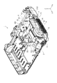
図2は、冷却機構4が外装筐体2に設置された斜視図である。図3は、冷却機構4と外装筐体2とを分離した斜視図である。図2、図3を含む以降の図面では、説明の便宜上、XYZ直交座標系を用いる。XYZ直交座標系は、図示省略しているが投写レンズ36の投写方向をX(+)方向とし、X方向に直交し、外気導入口25の方向をY(+)方向とする。また、X方向およびY方向に直交し、かつ、プロジェクター1を机上に設置した姿勢での上方向をZ(+)方向とする。また、X(+)方向を前方向(前側)、X(−)方向を後方向(後側)、Y(+)方向を右方向(右側)、Y(−)方向を左方向(左側)、Z(+)方向を上方向(上側)、Z(−)方向を下方向(下側)、として適宜使用する。
[Configuration and operation of cooling mechanism 4]
FIG. 2 is a perspective view in which the
図2、図3では、プロジェクター1を構成する構成部の中で要部のみを示している。要部として、外装筐体2を構成する下ケース21と、下ケース21に固定される冷却機構4とを示している。なお、外装筐体2は、本実施形態では概六面体の偏平形状に形成されている。そして、外装筐体2は、下ケース21の他、上ケース、フロントケース、リアケース(いずれも図示省略)等で構成されている。
2 and 3, only the main part is shown among the constituent parts constituting the projector 1. As main parts, a
図2、図3に示すように、下ケース21の右前方向の側面には、冷却ファン5が外気を吸気する際の導入口となるスリット状の複数の孔を有する外気導入口25が設置されている。この外気導入口25は、図示省略する上ケースにも同様の領域に外気導入口25が設置されている。また、外気導入口25の内側(外装筐体2の内面側)には、外気導入口25に相対する領域に、外気導入口25から導入される外気に含まれる塵埃を取り除く着脱可能なフィルター26が設置されている。
As shown in FIGS. 2 and 3, an
冷却機構4は、冷却ファン5の吸気口52がフィルター26に向き合うように、プロジェクター1(下ケース21)の右前方向のコーナー部に設置される。冷却機構4は、冷却ファン5、冷却ファン5を固定する固定枠としての第1固定枠6、冷却ファン5の一部を覆い第1固定枠6に設置される第2固定枠7とで概ね構成されている。
The
冷却ファン5は、本実施形態では、いわゆるシロッコファンを用いている。シロッコファンは、回転軸方向から吸気した空気(外気)を、回転による遠心力方向に吐出するファンである。冷却ファン5は、略円柱形状の本体51内部に羽根車等の駆動系(図示省略)が設置され、回転中心軸Aの方向に略垂直となる本体51の面には、外気を吸気する第1の吸気口52が形成される。また、本実施形態の冷却ファン5は、この吸気口52に相対する本体51の反対側の面にも第2の吸気口53(図5)が形成され、この吸気口53からも外気を吸気する。第1の吸気口52はメインの吸気口となり、第2の吸気口53はサブの吸気口となる。吸気口52は、フィルター26に向かい合うように設置されている。また、本体51には、吸気した外気を遠心力方向に吐出する吐出口54(図3)が形成されている。
In the present embodiment, the cooling
冷却ファン5は、駆動することにより、外気導入口25およびフィルター26を介し、吸気口52から外気を吸気する。また、吸気口53からも外気を吸気する。そして、吸気した外気を吐出口54から吐出する。なお、図2、図3では、外気導入口25と吸気口52との間に位置するフィルター26が図示省略されている。
The cooling
第1固定枠6は、冷却ファン5を固定すると共に、冷却を必要とする光学部品に外気を流動するダクトの一部を構成している。なお、ダクトは、下ケース21にも第1固定枠6のダクトに対応する位置にダクトの一部が形成されており、下ケース21の所定の位置に第1固定枠6を設置することにより、外気が流動可能となるダクトが形成される構成となっている。また、第2固定枠7は、第1固定枠6の上部に位置し、冷却ファン5を覆うと共に、フィルター26を介して吸気される外気を第1固定枠6と共に、第2の吸気口53に流動するダクトを構成している。
The first
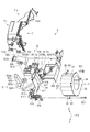
図4、図5は、冷却機構4の分解斜視図である。詳細には、図4は、冷却機構4の右側を上方向から見た分解斜視図であり、図5は、図4の冷却機構4を反対方向から見た分解斜視図である。
4 and 5 are exploded perspective views of the
〔冷却ファン5、第1固定枠6の構成〕
冷却ファン5は、本体51の側面に、孔部551を有する固定部55が2つ形成され、孔部551には冷却ファン5を固定する際に第1ネジSC1が挿通される。
第1固定枠6は、冷却ファン5を固定する概ね板状に形成される板状部61と、板状部61の下方向となる一端部611の後方向に接続してダクト(ダクトの一部)を構成するダクト構成部62とを有して形成されている。
[Configuration of
In the cooling
The first
板状部61は、冷却ファン5のサブの吸気口53の左方向に位置し、吸気口53を一部露出させる切欠き部612を有している。板状部61の下方向の端部となる一端部611には、左方向に延出する延出部613が2つ形成されている。2つの延出部613には、板状部61を下ケース21に固定するための孔部614がそれぞれ形成され、孔部614には固定する際、固定用の第2ネジSC2が挿通される。なお、2つの孔部614は、一端部611の近傍で、一端部611に沿うように形成されている。
The plate-
一端部611の前方向(切欠き部612の前方向)には、右方向に延出する壁部615が形成され、壁部615の後側面には、冷却ファン5を固定する固定部(後述する固定部619と同様)が形成されている。また、壁部615の前側面には、第2固定枠7を係止するための突起部616が形成されている。
A
板状部61の上方向の端部で、一端部611に相対する他端部617には、右方向に延出して冷却ファン5の本体51の上部を一部覆うカバー部618が形成されている。カバー部618の後方向には、冷却ファン5を固定する固定部619が右方向に突出して形成されている。なお、冷却ファン5は、冷却ファン5の2つの固定部55を、板状部61の2つの固定部619に右方向からそれぞれ当接させ、第1ネジSC1により固定部619のネジ孔619aに螺合させることで、板状部61に固定される。
A
〔ダクト構成部62の構成〕
図6は、冷却機構4を上下反転した状態の斜視図である。図4〜図6を参照して、ダクト構成部62の構成と動作を説明する。ダクト構成部62は、冷却ファン5の吐出口54から吐出された外気を流動させるダクトを構成する部分である。ダクト構成部62は、本実施形態では、冷却ファン5の吐出口54から吐出された外気を、吐出口54に接続する導入口620から流入させ、冷却を必要とする3カ所に流動させている。
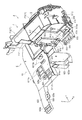
[Configuration of Duct Component 62]
FIG. 6 is a perspective view showing a state in which the
ダクト構成部62は、本実施形態では、液晶パネル351、射出側偏光板353をメインに冷却するためのダクトを構成する第1ダクト621と、偏光変換素子323を冷却するためのダクトを構成する第2ダクト622と、光源装置31を冷却するためのダクトを構成する第3ダクト623とで構成されている。なお、ダクト構成部62は、この3つのダクト621,622,623が結合して構成されている。言い換えると、各ダクト621,622,623は、複数の隔壁624により仕切られることにより構成されている。
In this embodiment, the
第1ダクト621は、G光用の液晶パネル351G側に流動させるダクト6211と、R光用およびB光用の液晶パネル351R,3521B側に流動させるダクト6212との2つに分岐されている。分岐されたG光用のダクト6211の先端部には、複数の吐出口6211aが形成されている。また、分岐されたR光用およびB光用のダクト6212には、根元部にR光用の2つの吐出口6212aと、先端部にB光用の2つの吐出口6212bとが形成されている。
The
第2ダクト622は、先端部に吐出口622aが形成されている。第3ダクト623は、先端部に段差をつけた2つの吐出口623aが形成されている。
The
〔サブダクト構成部22の概構成〕
下ケース21の内面には、ダクト構成部62に相対して構成されるサブダクト構成部22(図3)が形成されている。サブダクト構成部22は、第1ダクト621に対応する第1サブダクト221と、第2ダクト622に対応する第2サブダクト222と、第3ダクト623に対応する第3サブダクト223とで構成されている。
[General configuration of sub-duct component 22]
On the inner surface of the
ダクト構成部62(冷却機構4)が下ケース21に設置されることにより、ダクト構成部62とサブダクト構成部22とが係合し、各ダクトが完成する。詳細には、第1ダクト621と第1サブダクト221とが係合し、第2ダクト622と第2サブダクト222とが係合し、第3ダクト623と第3サブダクト223とが係合することにより、各ダクトが完成する。
By installing the duct component 62 (cooling mechanism 4) in the
なお、ダクト構成部62には、上面の一段窪んだ面に、第2固定枠7の後述するダクト部712(壁部7121)に対応して起立して形成される壁部626が形成されている。この壁部626と、壁部626に囲まれて右方向の端部に至る面部627とは、後述する第4ダクト71の一部を構成する。
Note that the
〔第2固定枠7の構成〕
図7は、冷却機構4の斜視図である。詳細には、図7は、冷却機構4の左側を上方向から見た斜視図である。図4〜図7を参照して、第2固定枠7の構成を説明する。
第2固定枠7は、上述したように、第1固定枠6の上部に位置し、冷却ファン5の上部を覆い、冷却ファン5の駆動によりフィルター26を介して吸気される外気を第1固定枠6と共にサブの吸気口53に流動するダクト構成部として構成されている。なお、第2固定枠7がダクト構成部として構成するダクトを第4ダクト71とする。
[Configuration of Second Fixed Frame 7]
FIG. 7 is a perspective view of the
As described above, the second fixed
第2固定枠7は、冷却ファン5の上部を覆うと共に、板状部61の切欠き部612および壁部615の外周に沿った形状に形成されて冷却ファン5を覆うカバー部711が形成されている。カバー部711の左方向の下端部には、図7に示すように、左方向に延出して形成され、第2固定枠7を第1固定枠6に固定するための固定部7111が形成され、固定部7111には第2ネジSC2を挿通する孔部7111aが形成されている。また、カバー部711の前方向の外面には、第2固定枠7を第1固定枠6に係止するための係止部7112が形成されている。
The second
第2固定枠7は、カバー部711の後方向に接続し、右方向を開口させて、フィルター26を介して吸気した外気を流動させるダクト部712が形成されている。ダクト部712の左側の壁(左側面)を構成する壁部7121は、第2固定枠7を第1固定枠6に固定することにより、ダクト構成部62に形成される壁部626と係合する。
The second
〔第2固定枠7の第1固定枠6への固定〕
第2固定枠7を第1固定枠6に固定する場合は、第1固定枠6の上方から第2固定枠7を設置する。詳細には、第1固定枠6の突起部616に第2固定枠7の係止部7112を係止する。併せて、第2固定枠7のダクト部712後方向に形成される図示省略する突起部に、第1固定枠6の図示省略する係止部を係止する。また、図7に示すように、第2固定枠7に形成される固定部7111を、第1固定枠6の一方の延出部613の上面に当接させて重ねた状態とし、第2ネジSC2を孔部7111aと孔部614に挿通し、下ケース21にネジ締めする。なお、下ケース21へのネジ締めは、冷却機構4として下ケース21に固定する際に併せて行う。
[Fixing of the second fixed
When the second fixed
〔冷却機構4の下ケース21への固定〕
ダクト構成部62には、下ケース21に固定するための4つの固定部625が孔部625a(図6、図7)を有して形成されている。また、下ケース21には、図3に示すように、この固定部625に対応して、4つの固定部225が突出して形成されている。また、板状部61の2つの延出部613に形成される孔部614に対応して、突出する2つの固定部224が形成されている。
[Fixing to the
The
冷却機構4を下ケース21に固定する際には、ダクト構成部62の固定部625を下ケース21の固定部225に当接させ、また、板状部61の延出部613を下ケース21の固定部224に当接させる。次に、固定部625の孔部625aからネジSC3を挿通して、下ケース21の固定部225のネジ孔225aに螺合させる。
When the
また、延出部613の上部には、上述した第2固定枠7の固定部7111が重なっており、固定部7111の孔部7111aから第2ネジSC2を挿通し、延出部613の孔部614にも挿通した後、下ケース21の固定部224のネジ孔224aに螺合させる。これにより、冷却機構4を下ケース21に固定することができる。
In addition, the fixing
冷却機構4を下ケース21に固定することにより、各ダクトが完成する。本実施形態では、上述したように、第1ダクト621、第2ダクト622、第3ダクト623が完成する。
Each duct is completed by fixing the
〔第4ダクト71の詳細と外気の流動〕
冷却機構4を下ケース21に固定することにより、第4ダクト71は、第2固定枠7のダクト部712と、第1固定枠6の壁部626および面部627とで囲まれた空間がダクトとして形成される。そして、冷却ファン5が駆動した場合、この空間に、外気導入口25、フィルター26を介した外気が流入する。
[Details of the
By fixing the
また、第4ダクト71は、ダクト部712とカバー部711との接続部分を含め、板状部61の内面およびカバー部711の内面と、冷却ファン5と、下ケース21のサブダクト構成部22とに囲まれた空間がダクトとして形成される。流入した外気は、この空間を流動して、冷却ファン5のサブの吸気口53を介して冷却ファン5内部に流入する。
Further, the
〔冷却機構4(ダクト構成部62)における外気の流動〕
冷却機構4は、冷却ファン5が駆動することにより、外気導入口25、フィルター26を介して外気をメインの吸気口52から冷却ファン5内部に流入させる。流入した外気は、吐出口54から吐出され、ダクト構成部62の導入口620を介してダクト構成部62内部に流入する。なお、第4ダクト71内部を流動してサブの吸気口53から冷却ファン5内部に流入した外気も、同様に、吐出口54から吐出されてダクト構成部62内部に流入する。
[Flow of Outside Air in Cooling Mechanism 4 (Duct Component 62)]
The
ダクト構成部62の内部に流入した外気は、隔壁624により、各ダクト621,622,623に分岐されて流動する。第1ダクト621を流動する外気は、途中で2つのダクト6211,6212に分岐されて流動する。
The outside air that has flowed into the
そして、ダクト6211を流動する外気は、吐出口6211aから上方向に吐出される。なお、吐出口6211aは、光学ユニット3の光学装置35を構成する緑色光用の液晶パネル351Gおよび緑色光用の射出側偏光板353の下方向に位置している。そのため、吐出口6211aから上方向に吐出した外気は、緑色光用の液晶パネル351G、緑色光用の射出側偏光板353に下方向から吹き付ける状態となる。これにより、発熱する緑色光用の液晶パネル351G、緑色光用の射出側偏光板353の熱を奪う。
And the external air which flows through the
また、ダクト6212を流動する外気は、分岐された直後に吐出口6212aから一部の外気が上方向に吐出する。また、残りの外気は、ダクト6212を流動し、吐出口6212bから上方向に吐出する。なお、吐出口6212aは、光学ユニット3の光学装置35を構成する赤色光用の液晶パネル351Rおよび赤色光用の射出側偏光板353の下方向に位置している。そのため、吐出口6212aから上方向に吐出した外気は、赤色光用の液晶パネル351R、赤色光用の射出側偏光板353に下方向から吹き付ける状態となる。これにより、発熱する赤色光用の液晶パネル351R、赤色光用の射出側偏光板353の熱を奪う。
In addition, a part of the outside air flowing through the
また、吐出口6212bは、光学ユニット3の光学装置35を構成する青色光用の液晶パネル351Bおよび青色光用の射出側偏光板353の下方向に位置している。そのため、吐出口6212bから上方向に吐出した外気は、青色光用の液晶パネル351B、青色光用の射出側偏光板353に下方向から吹き付ける状態となる。これにより、発熱する青色光用の液晶パネル351B、青色光用の射出側偏光板353の熱を奪う。
Further, the
第2ダクト622を流動する外気は、吐出口622aから上方向に吐出される。なお、吐出口622aは、光学ユニット3の照明光学装置32を構成する偏光変換素子323の下方向に位置している。そのため、吐出口622aから上方向に吐出した外気は、偏光変換素子323に下方向から吹き付ける状態となる。これにより、発熱する偏光変換素子323の熱を奪う。
The outside air flowing through the
第3ダクト623を流動する外気は、段差をつけた2つの吐出口623aから水平方向(左方向に)に吐出される。なお、吐出口623aは、光源装置31の右側面に位置している。そのため、吐出口623aから左方向に吐出した外気は、光源装置31の右方向から吹き付け、光源装置31の内部を流動する状態となる。これにより、発熱する光源装置31の熱を奪う。
The outside air flowing through the
なお、各光学部品を冷却して温まった空気(外気)は、上述したように、図示省略する排気用のファンにより、外装筐体2の外部に排気口(図示省略)を介して排気される。
冷却機構4の以上の動作により、発熱する所定の光学部品を冷却することができる。
Note that air (outside air) that has been heated by cooling each optical component is exhausted to the outside of the
With the above operation of the
〔固定された板状部61の状態〕
冷却機構4を下ケース21に固定した状態において、板状部61は、冷却ファン5を固定し、延出部613が第2ネジSC2により下ケース21に固定される状態となる。言い換えると、板状部61の一端部611が下ケース21に固定される状態となる。なお、他端部617は、第2固定枠7のカバー部711とは係合せず左右方向に移動可能な状態(言い換えると解放された状態)となる。従って、板状部61は、いわゆる片持ち梁の状態となっている。
[State of the fixed plate-like portion 61]
In a state where the
〔プロジェクター1が落下した際の板状部61の動作〕
冷却機構4を下ケース21に固定する組み立てを含め、プロジェクター1が組み立てられた状態(プロジェクター1の完成体)で、プロジェクター1を所定の方向で、落下させた場合の板状部61の動作を説明する。
[Operation of the plate-
The operation of the plate-
本実施形態でのプロジェクター1の落下方向(衝撃が加えられる方向)は、所定の方向として、板状部61の面に略垂直となる方向にプロジェクター1を落下させるものとする。言い換えると、冷却ファン5の回転中心軸Aを上下方向(鉛直方向)として、冷却ファン5の吸気口52が下方向(プロジェクター1(外装筐体2)の右側面が下方向)となる落下を行う。すなわち、本実施形態における所定の落下方向とは、冷却ファン5の回転中心軸Aの略延出方向、及び板状部61の面に略垂直となる方向となる。このような方向で落下を行った場合、延出部613(一端部611)が第2ネジSC2により固定されると共に、冷却ファン5を固定した板状部61は、落下方向に撓むことにより、冷却ファン5への衝撃を低減させる。そして、落下後には、板状部61の有する可撓性により、元の位置に戻ることができる。
In this embodiment, the projector 1 is dropped in a direction (direction in which an impact is applied) as a predetermined direction, and the projector 1 is dropped in a direction substantially perpendicular to the surface of the plate-
本実施形態のプロジェクター1によれば、以下の効果が得られる。 According to the projector 1 of the present embodiment, the following effects can be obtained.
本実施形態の電子機器としてのプロジェクター1は、冷却ファン5を固定した板状部61を、概ね片持ち梁の構造とすることができ、所定の落下方向(衝撃が加えられる方向)として板状部61対して略垂直方向となる落下方向で落下した場合、板状部61が落下方向に撓むことにより、落下による冷却ファン5への衝撃を吸収させることができる。これにより、冷却ファン5を備えたプロジェクター1において、落下の衝撃による冷却ファン5への影響を低減させたプロジェクター1を実現することができる。
In the projector 1 as the electronic apparatus according to the present embodiment, the plate-
本実施形態の冷却ファン5は、回転中心軸Aに対して略平行な方向に挿通される第1ネジSC1により板状部61に固定されている。これにより、落下衝撃が直接的に板状部61へ伝搬され、板状部61が衝撃で搖動することにより、落下の衝撃による冷却ファン5への影響を低減させることができる。
The cooling
本実施形態のプロジェクター1は、延出部613の複数の孔部614が、板状部61の一端部611に沿うように設置されることにより、板状部61が更に撓みやすくなり、落下の衝撃を吸収しやすくなることで、衝撃による冷却ファン5への影響を更に低減させることができる。
In the projector 1 according to the present embodiment, the plurality of
本実施形態のプロジェクター1は、固定枠(第1固定枠6)がダクト(第1ダクト621、第2ダクト622、第3ダクト623)の一部を構成することにより、冷却ファン5が吸気した空気を流動して、発熱する部品を冷却させることができる。
In the projector 1 according to the present embodiment, the fixed frame (first fixed frame 6) forms part of the duct (the
なお、上述した実施形態に限定されず、その要旨を逸脱しない範囲において種々の変更や改良などを加えて実施することが可能である。変形例を以下に述べる。 The present invention is not limited to the above-described embodiment, and various modifications and improvements can be made without departing from the scope of the invention. A modification will be described below.
前記実施形態では、電子機器としてのプロジェクター1に本発明を適用しているが、これに限られず、プロジェクター1以外の、冷却ファンを備えた電子機器に対しても本発明を適用することができる。 In the above embodiment, the present invention is applied to the projector 1 as an electronic apparatus. However, the present invention is not limited to this, and the present invention can also be applied to an electronic apparatus including a cooling fan other than the projector 1. .
前記実施形態では、使用するシロッコファン(冷却ファン5)が、サブの吸気口(吸気口53)からの吸気を必要とする仕様のため、第2固定枠7を用いているが、サブの吸気口を必要としない仕様の場合には、第2固定枠を用いなくてもよい。
In the embodiment, the second fixed
前記実施形態では、冷却ファン5の吸気口52が、プロジェクター1(下ケース21)の右前方向のコーナー部に設置されるとしたが、吸気口52が別の位置に設置されてもよい。言い換えると、例えば、吸気口52が下ケース21の下方向側に設置され、冷却ファン5の回転中心軸Aの方向が、プロジェクター1を机上に設置した姿勢での上下方向と略一致するように構成してもよい。
In the above-described embodiment, the
前記実施形態の第1固定枠6を構成する板状部61の形状や、ダクト構成部62のダクトの数や形状などは適宜変更することができる。
The shape of the plate-
前記実施形態のプロジェクター1は、放電式ランプを用いている。放電式ランプとしては、メタルハライドランプ、高圧水銀ランプ、超高圧水銀ランプ等、高輝度発光する種々のランプを用いることができる。 The projector 1 according to the embodiment uses a discharge lamp. As the discharge lamp, various lamps that emit light with high brightness such as a metal halide lamp, a high-pressure mercury lamp, and an ultra-high pressure mercury lamp can be used.
前記実施形態のプロジェクター1は、光変調装置として液晶パネル351を用いている。なお、液晶パネル351としては、透過型の液晶パネルや反射型の液晶パネルを用いることができる。
The projector 1 of the embodiment uses a
前記実施形態のプロジェクター1は、液晶パネル351を光変調装置として用いている。しかし、これに限られず、マイクロミラー型の光変調装置等、液晶パネルとは異なる他の方式の光変調装置を用いることができる。なお、マイクロミラー型の光変調装置としては、例えば、DMD(Digital Micromirror Device)を用いることができる。
The projector 1 according to the embodiment uses the
1…プロジェクター(電子機器)、2…外装筐体、5…冷却ファン、6…第1固定枠(固定枠)、31…光源装置、36…投写レンズ、351…液晶パネル(光変調装置)、61…板状部、611…一端部、617…他端部、613…延出部、614…孔部、621…第1ダクト、622…第2ダクト、623…第3ダクト、71…第4ダクト(ダクト)、A…回転中心軸、SC1…第1ネジ、SC2…第2ネジ。 DESCRIPTION OF SYMBOLS 1 ... Projector (electronic device), 2 ... Exterior housing, 5 ... Cooling fan, 6 ... 1st fixed frame (fixed frame), 31 ... Light source device, 36 ... Projection lens, 351 ... Liquid crystal panel (light modulation device), 61 ... Plate-shaped part, 611 ... One end part, 617 ... Other end part, 613 ... Extension part, 614 ... Hole part, 621 ... First duct, 622 ... Second duct, 623 ... Third duct, 71 ... Fourth Duct (duct), A ... central axis of rotation, SC1 ... first screw, SC2 ... second screw.
Claims (5)
前記固定枠は、前記冷却ファンを固定する板状部を有し、
前記板状部は、前記外装筐体に一端部が固定され、他端部は解放されると共に、前記冷却ファンの回転中心軸の延出方向に対して略垂直となるように設置され、当該電子機器に衝撃が加えられた際、前記回転中心軸の略延出方向に撓む可撓性を有していることを特徴とする電子機器。 An electronic device comprising a cooling fan, a fixed frame that fixes the cooling fan, and an exterior housing that fixes the fixed frame,
The fixed frame has a plate-like portion for fixing the cooling fan,
The plate-like portion is installed so that one end portion is fixed to the exterior casing and the other end portion is released and is substantially perpendicular to the extending direction of the rotation center axis of the cooling fan, An electronic device characterized by having flexibility to bend in a substantially extending direction of the rotation center axis when an impact is applied to the electronic device.
前記冷却ファンは、前記回転中心軸と略平行な方向に挿通される第1ネジにより前記板状部に固定されることを特徴とする電子機器。 The electronic device according to claim 1,
The electronic device, wherein the cooling fan is fixed to the plate-like portion by a first screw inserted in a direction substantially parallel to the rotation center axis.
前記板状部は、前記一端部から延出する延出部を有し、
前記延出部には、前記一端部に沿うように、前記外装筐体にネジによる固定を行うための複数の孔部を備えていることを特徴とする電子機器。 The electronic device according to claim 1 or 2,
The plate-like part has an extension part extending from the one end part,
The electronic device according to claim 1, wherein the extension portion includes a plurality of holes for fixing the exterior casing with screws along the one end portion.
前記固定枠は、前記冷却ファンが吸気した空気を流動するダクトの一部を構成していることを特徴とする電子機器。 The electronic device according to any one of claims 1 to 3,
2. The electronic apparatus according to claim 1, wherein the fixed frame constitutes a part of a duct that flows the air taken in by the cooling fan.
光を射出する光源装置と、
前記光源装置から射出された前記光を画像情報に応じて変調する光変調装置と、
前記光変調装置で変調された変調光を投写する投写レンズと、
を備えていることを特徴とする電子機器。 The electronic device according to any one of claims 1 to 4,
A light source device for emitting light;
A light modulation device that modulates the light emitted from the light source device according to image information;
A projection lens that projects the modulated light modulated by the light modulator;
An electronic device comprising:
Priority Applications (3)
| Application Number | Priority Date | Filing Date | Title |
|---|---|---|---|
| JP2014230439A JP2016095356A (en) | 2014-11-13 | 2014-11-13 | Electronic apparatus |
| CN201510728204.1A CN105607398B (en) | 2014-11-13 | 2015-10-30 | Electronic equipment |
| US14/931,467 US20160143183A1 (en) | 2014-11-13 | 2015-11-03 | Electronic apparatus |
Applications Claiming Priority (1)
| Application Number | Priority Date | Filing Date | Title |
|---|---|---|---|
| JP2014230439A JP2016095356A (en) | 2014-11-13 | 2014-11-13 | Electronic apparatus |
Publications (2)
| Publication Number | Publication Date |
|---|---|
| JP2016095356A true JP2016095356A (en) | 2016-05-26 |
| JP2016095356A5 JP2016095356A5 (en) | 2017-11-09 |
Family
ID=55963051
Family Applications (1)
| Application Number | Title | Priority Date | Filing Date |
|---|---|---|---|
| JP2014230439A Withdrawn JP2016095356A (en) | 2014-11-13 | 2014-11-13 | Electronic apparatus |
Country Status (3)
| Country | Link |
|---|---|
| US (1) | US20160143183A1 (en) |
| JP (1) | JP2016095356A (en) |
| CN (1) | CN105607398B (en) |
Families Citing this family (1)
| Publication number | Priority date | Publication date | Assignee | Title |
|---|---|---|---|---|
| US11044828B2 (en) * | 2019-09-30 | 2021-06-22 | Coretronic Corporation | Projector |
Citations (8)
| Publication number | Priority date | Publication date | Assignee | Title |
|---|---|---|---|---|
| JPS6454390U (en) * | 1987-09-30 | 1989-04-04 | ||
| JP2004138911A (en) * | 2002-10-18 | 2004-05-13 | Seiko Epson Corp | Blowing apparatus and projector equipped with the blowing apparatus |
| US20080030690A1 (en) * | 2006-08-07 | 2008-02-07 | Yi-Ting Hsu | Projection Device with a Blower and a Nozzle disposed on a Bracket |
| JP2008071830A (en) * | 2006-09-12 | 2008-03-27 | Sharp Corp | Fan supporting device and video display |
| JP2009104031A (en) * | 2007-10-25 | 2009-05-14 | Canon Inc | Image projector |
| US20100108855A1 (en) * | 2008-11-05 | 2010-05-06 | Qisda Corporation | Electronic apparatus and rotating module thereof |
| JP2011141501A (en) * | 2010-01-09 | 2011-07-21 | Seiko Epson Corp | Projector |
| WO2011111203A1 (en) * | 2010-03-11 | 2011-09-15 | Necディスプレイソリューションズ株式会社 | Projection display device |
Family Cites Families (8)
| Publication number | Priority date | Publication date | Assignee | Title |
|---|---|---|---|---|
| JP3467697B2 (en) * | 2001-05-16 | 2003-11-17 | セイコーエプソン株式会社 | Cooling device for electro-optical device and projector |
| TWM313415U (en) * | 2006-12-07 | 2007-06-01 | Inventec Corp | Fixing mechanism for fan frame use |
| JP4513820B2 (en) * | 2007-03-28 | 2010-07-28 | セイコーエプソン株式会社 | projector |
| JP2010134028A (en) * | 2008-12-02 | 2010-06-17 | Sony Corp | Blower for electronic equipment and electronic equipment with the blower |
| CN102109213B (en) * | 2009-12-23 | 2014-07-02 | 乐金电子(天津)电器有限公司 | Guide shell structure of dehumidifier |
| JP2012193971A (en) * | 2011-03-15 | 2012-10-11 | Seiko Epson Corp | Sensor module, sensor device, manufacturing method of sensor device and electronic apparatus |
| JP6119183B2 (en) * | 2012-10-19 | 2017-04-26 | セイコーエプソン株式会社 | projector |
| JP2014165573A (en) * | 2013-02-22 | 2014-09-08 | Seiko Epson Corp | Vibration piece, vibrator, electronic device, electronic apparatus, and movable body |
-
2014
- 2014-11-13 JP JP2014230439A patent/JP2016095356A/en not_active Withdrawn
-
2015
- 2015-10-30 CN CN201510728204.1A patent/CN105607398B/en active Active
- 2015-11-03 US US14/931,467 patent/US20160143183A1/en not_active Abandoned
Patent Citations (8)
| Publication number | Priority date | Publication date | Assignee | Title |
|---|---|---|---|---|
| JPS6454390U (en) * | 1987-09-30 | 1989-04-04 | ||
| JP2004138911A (en) * | 2002-10-18 | 2004-05-13 | Seiko Epson Corp | Blowing apparatus and projector equipped with the blowing apparatus |
| US20080030690A1 (en) * | 2006-08-07 | 2008-02-07 | Yi-Ting Hsu | Projection Device with a Blower and a Nozzle disposed on a Bracket |
| JP2008071830A (en) * | 2006-09-12 | 2008-03-27 | Sharp Corp | Fan supporting device and video display |
| JP2009104031A (en) * | 2007-10-25 | 2009-05-14 | Canon Inc | Image projector |
| US20100108855A1 (en) * | 2008-11-05 | 2010-05-06 | Qisda Corporation | Electronic apparatus and rotating module thereof |
| JP2011141501A (en) * | 2010-01-09 | 2011-07-21 | Seiko Epson Corp | Projector |
| WO2011111203A1 (en) * | 2010-03-11 | 2011-09-15 | Necディスプレイソリューションズ株式会社 | Projection display device |
Also Published As
| Publication number | Publication date |
|---|---|
| US20160143183A1 (en) | 2016-05-19 |
| CN105607398A (en) | 2016-05-25 |
| CN105607398B (en) | 2017-08-08 |
Similar Documents
| Publication | Publication Date | Title |
|---|---|---|
| JP5381449B2 (en) | projector | |
| JP4428434B2 (en) | Optical device and projector | |
| JP2008257175A (en) | Power source unit and projection type image display apparatus using the same | |
| JP4046119B2 (en) | Lighting device, projector | |
| JP4650331B2 (en) | projector | |
| JP5140379B2 (en) | Optical component cooling mechanism and projection display apparatus using the same | |
| JP2004246108A (en) | Duct, cooling unit, and projector | |
| JP6205864B2 (en) | projector | |
| JP2006208488A (en) | Rear projector | |
| JPWO2004036307A1 (en) | Optical device and projector | |
| JP2010266881A (en) | Projector | |
| JP2012008179A (en) | Projector | |
| JP2012048050A (en) | Projection type video display device | |
| US8282218B2 (en) | Projector having duct for guiding air from exhaust fan to exhaust port | |
| JP5216298B2 (en) | Projection display device | |
| JP2016095356A (en) | Electronic apparatus | |
| JP2010230779A (en) | Projector | |
| JP2006227428A (en) | Case for optical components, and projector | |
| JP4428243B2 (en) | Rear projector | |
| JP5176457B2 (en) | projector | |
| JP2009042329A (en) | Image projection device | |
| JP5109558B2 (en) | projector | |
| JP2011002612A (en) | Projector | |
| JP2008176010A (en) | Projector | |
| JP4423997B2 (en) | projector |
Legal Events
| Date | Code | Title | Description |
|---|---|---|---|
| RD03 | Notification of appointment of power of attorney |
Free format text: JAPANESE INTERMEDIATE CODE: A7423 Effective date: 20160623 |
|
| A521 | Request for written amendment filed |
Free format text: JAPANESE INTERMEDIATE CODE: A523 Effective date: 20170927 |
|
| A621 | Written request for application examination |
Free format text: JAPANESE INTERMEDIATE CODE: A621 Effective date: 20170927 |
|
| A977 | Report on retrieval |
Free format text: JAPANESE INTERMEDIATE CODE: A971007 Effective date: 20180725 |
|
| A131 | Notification of reasons for refusal |
Free format text: JAPANESE INTERMEDIATE CODE: A131 Effective date: 20180731 |
|
| RD05 | Notification of revocation of power of attorney |
Free format text: JAPANESE INTERMEDIATE CODE: A7425 Effective date: 20180905 |
|
| A761 | Written withdrawal of application |
Free format text: JAPANESE INTERMEDIATE CODE: A761 Effective date: 20181001 |