JP2016016828A - Brake fluid controller - Google Patents
Brake fluid controller Download PDFInfo
- Publication number
- JP2016016828A JP2016016828A JP2014142493A JP2014142493A JP2016016828A JP 2016016828 A JP2016016828 A JP 2016016828A JP 2014142493 A JP2014142493 A JP 2014142493A JP 2014142493 A JP2014142493 A JP 2014142493A JP 2016016828 A JP2016016828 A JP 2016016828A
- Authority
- JP
- Japan
- Prior art keywords
- sleeve
- flange portion
- valve seat
- assembly hole
- housing
- Prior art date
- Legal status (The legal status is an assumption and is not a legal conclusion. Google has not performed a legal analysis and makes no representation as to the accuracy of the status listed.)
- Pending
Links
Images


Classifications
-
- B—PERFORMING OPERATIONS; TRANSPORTING
- B60—VEHICLES IN GENERAL
- B60T—VEHICLE BRAKE CONTROL SYSTEMS OR PARTS THEREOF; BRAKE CONTROL SYSTEMS OR PARTS THEREOF, IN GENERAL; ARRANGEMENT OF BRAKING ELEMENTS ON VEHICLES IN GENERAL; PORTABLE DEVICES FOR PREVENTING UNWANTED MOVEMENT OF VEHICLES; VEHICLE MODIFICATIONS TO FACILITATE COOLING OF BRAKES
- B60T15/00—Construction arrangement, or operation of valves incorporated in power brake systems and not covered by groups B60T11/00 or B60T13/00
- B60T15/02—Application and release valves
- B60T15/025—Electrically controlled valves
- B60T15/028—Electrically controlled valves in hydraulic systems
-
- B—PERFORMING OPERATIONS; TRANSPORTING
- B60—VEHICLES IN GENERAL
- B60T—VEHICLE BRAKE CONTROL SYSTEMS OR PARTS THEREOF; BRAKE CONTROL SYSTEMS OR PARTS THEREOF, IN GENERAL; ARRANGEMENT OF BRAKING ELEMENTS ON VEHICLES IN GENERAL; PORTABLE DEVICES FOR PREVENTING UNWANTED MOVEMENT OF VEHICLES; VEHICLE MODIFICATIONS TO FACILITATE COOLING OF BRAKES
- B60T8/00—Arrangements for adjusting wheel-braking force to meet varying vehicular or ground-surface conditions, e.g. limiting or varying distribution of braking force
- B60T8/17—Using electrical or electronic regulation means to control braking
- B60T8/176—Brake regulation specially adapted to prevent excessive wheel slip during vehicle deceleration, e.g. ABS
-
- B—PERFORMING OPERATIONS; TRANSPORTING
- B60—VEHICLES IN GENERAL
- B60T—VEHICLE BRAKE CONTROL SYSTEMS OR PARTS THEREOF; BRAKE CONTROL SYSTEMS OR PARTS THEREOF, IN GENERAL; ARRANGEMENT OF BRAKING ELEMENTS ON VEHICLES IN GENERAL; PORTABLE DEVICES FOR PREVENTING UNWANTED MOVEMENT OF VEHICLES; VEHICLE MODIFICATIONS TO FACILITATE COOLING OF BRAKES
- B60T13/00—Transmitting braking action from initiating means to ultimate brake actuator with power assistance or drive; Brake systems incorporating such transmitting means, e.g. air-pressure brake systems
- B60T13/10—Transmitting braking action from initiating means to ultimate brake actuator with power assistance or drive; Brake systems incorporating such transmitting means, e.g. air-pressure brake systems with fluid assistance, drive, or release
- B60T13/66—Electrical control in fluid-pressure brake systems
- B60T13/68—Electrical control in fluid-pressure brake systems by electrically-controlled valves
- B60T13/686—Electrical control in fluid-pressure brake systems by electrically-controlled valves in hydraulic systems or parts thereof
-
- B—PERFORMING OPERATIONS; TRANSPORTING
- B60—VEHICLES IN GENERAL
- B60T—VEHICLE BRAKE CONTROL SYSTEMS OR PARTS THEREOF; BRAKE CONTROL SYSTEMS OR PARTS THEREOF, IN GENERAL; ARRANGEMENT OF BRAKING ELEMENTS ON VEHICLES IN GENERAL; PORTABLE DEVICES FOR PREVENTING UNWANTED MOVEMENT OF VEHICLES; VEHICLE MODIFICATIONS TO FACILITATE COOLING OF BRAKES
- B60T8/00—Arrangements for adjusting wheel-braking force to meet varying vehicular or ground-surface conditions, e.g. limiting or varying distribution of braking force
- B60T8/32—Arrangements for adjusting wheel-braking force to meet varying vehicular or ground-surface conditions, e.g. limiting or varying distribution of braking force responsive to a speed condition, e.g. acceleration or deceleration
- B60T8/34—Arrangements for adjusting wheel-braking force to meet varying vehicular or ground-surface conditions, e.g. limiting or varying distribution of braking force responsive to a speed condition, e.g. acceleration or deceleration having a fluid pressure regulator responsive to a speed condition
- B60T8/36—Arrangements for adjusting wheel-braking force to meet varying vehicular or ground-surface conditions, e.g. limiting or varying distribution of braking force responsive to a speed condition, e.g. acceleration or deceleration having a fluid pressure regulator responsive to a speed condition including a pilot valve responding to an electromagnetic force
- B60T8/3615—Electromagnetic valves specially adapted for anti-lock brake and traction control systems
- B60T8/363—Electromagnetic valves specially adapted for anti-lock brake and traction control systems in hydraulic systems
-
- B—PERFORMING OPERATIONS; TRANSPORTING
- B60—VEHICLES IN GENERAL
- B60T—VEHICLE BRAKE CONTROL SYSTEMS OR PARTS THEREOF; BRAKE CONTROL SYSTEMS OR PARTS THEREOF, IN GENERAL; ARRANGEMENT OF BRAKING ELEMENTS ON VEHICLES IN GENERAL; PORTABLE DEVICES FOR PREVENTING UNWANTED MOVEMENT OF VEHICLES; VEHICLE MODIFICATIONS TO FACILITATE COOLING OF BRAKES
- B60T8/00—Arrangements for adjusting wheel-braking force to meet varying vehicular or ground-surface conditions, e.g. limiting or varying distribution of braking force
- B60T8/32—Arrangements for adjusting wheel-braking force to meet varying vehicular or ground-surface conditions, e.g. limiting or varying distribution of braking force responsive to a speed condition, e.g. acceleration or deceleration
- B60T8/34—Arrangements for adjusting wheel-braking force to meet varying vehicular or ground-surface conditions, e.g. limiting or varying distribution of braking force responsive to a speed condition, e.g. acceleration or deceleration having a fluid pressure regulator responsive to a speed condition
- B60T8/36—Arrangements for adjusting wheel-braking force to meet varying vehicular or ground-surface conditions, e.g. limiting or varying distribution of braking force responsive to a speed condition, e.g. acceleration or deceleration having a fluid pressure regulator responsive to a speed condition including a pilot valve responding to an electromagnetic force
- B60T8/3615—Electromagnetic valves specially adapted for anti-lock brake and traction control systems
- B60T8/3675—Electromagnetic valves specially adapted for anti-lock brake and traction control systems integrated in modulator units
- B60T8/368—Electromagnetic valves specially adapted for anti-lock brake and traction control systems integrated in modulator units combined with other mechanical components, e.g. pump units, master cylinders
-
- F—MECHANICAL ENGINEERING; LIGHTING; HEATING; WEAPONS; BLASTING
- F16—ENGINEERING ELEMENTS AND UNITS; GENERAL MEASURES FOR PRODUCING AND MAINTAINING EFFECTIVE FUNCTIONING OF MACHINES OR INSTALLATIONS; THERMAL INSULATION IN GENERAL
- F16K—VALVES; TAPS; COCKS; ACTUATING-FLOATS; DEVICES FOR VENTING OR AERATING
- F16K27/00—Construction of housing; Use of materials therefor
- F16K27/02—Construction of housing; Use of materials therefor of lift valves
- F16K27/029—Electromagnetically actuated valves
-
- F—MECHANICAL ENGINEERING; LIGHTING; HEATING; WEAPONS; BLASTING
- F16—ENGINEERING ELEMENTS AND UNITS; GENERAL MEASURES FOR PRODUCING AND MAINTAINING EFFECTIVE FUNCTIONING OF MACHINES OR INSTALLATIONS; THERMAL INSULATION IN GENERAL
- F16K—VALVES; TAPS; COCKS; ACTUATING-FLOATS; DEVICES FOR VENTING OR AERATING
- F16K31/00—Actuating devices; Operating means; Releasing devices
- F16K31/02—Actuating devices; Operating means; Releasing devices electric; magnetic
- F16K31/06—Actuating devices; Operating means; Releasing devices electric; magnetic using a magnet, e.g. diaphragm valves, cutting off by means of a liquid
- F16K31/0644—One-way valve
- F16K31/0655—Lift valves
Abstract
Description
本発明は、ブレーキ液が通過する流体通路を電磁弁により開閉するブレーキ用流体制御装置に関するものである。 The present invention relates to a brake fluid control device that opens and closes a fluid passage through which brake fluid passes by an electromagnetic valve.
従来、この種のブレーキ用流体制御装置として、例えば特許文献1に記載されたものがある。この特許文献1に記載されたブレーキ用流体制御装置は、ブレーキ液が流通する流体通路がハウジングに形成され、その流体通路が電磁弁により開閉されるようになっている。
Conventionally, as this type of brake fluid control device, for example, there is one described in
電磁弁は、プランジャが収容されるスリーブを備え、このスリーブにはスリーブの径方向外側に突出する円板状のフランジ部が形成されている。そして、ハウジングの組み付け穴内にフランジ部を挿入した後、組み付け穴の開口部周囲をかしめることによって、かしめによって変形した部分と組み付け穴の底部との間にフランジ部が挟持されている。 The solenoid valve includes a sleeve in which a plunger is accommodated, and the sleeve is formed with a disk-like flange portion that protrudes radially outward of the sleeve. And after inserting a flange part in the assembly hole of a housing, the flange part is clamped between the part deform | transformed by crimping and the bottom part of an assembly hole by crimping the circumference | surroundings of the opening part of an assembly hole.
また、フランジ部に楔部または溝部を形成することにより、ハウジングとの接触面における面圧を部分的に高めて、シール性を向上させるようにしている。 Further, by forming a wedge portion or a groove portion in the flange portion, the surface pressure at the contact surface with the housing is partially increased to improve the sealing performance.
しかしながら、フランジ部の楔部または溝部は、曲げ加工では形成が難しく、プレス成形による加工が容易ではない。また、楔部または溝部をプレス成形にて加工した場合は、楔部または溝部の加工精度が安定せず、その結果シール性が安定しないという問題が発生する。 However, it is difficult to form the wedge portion or groove portion of the flange portion by bending, and processing by press molding is not easy. Further, when the wedge portion or the groove portion is processed by press molding, the processing accuracy of the wedge portion or the groove portion is not stable, and as a result, the problem that the sealing performance is not stable occurs.
本発明は上記点に鑑みて、プレス成形による加工が容易で、且つ安定したシール性が得られるようにすることを目的とする。 In view of the above points, an object of the present invention is to facilitate processing by press molding and obtain a stable sealing property.
上記目的を達成するため、請求項1に記載の発明では、ハウジング(1)と電磁弁(2)とを備え、ハウジングは、ブレーキ液が流通する流体通路(10)と、一端の開口部(110)がハウジングの外部に開放されるともに、平坦な底部(111)が形成された組み付け穴(11)とを備え、電磁弁は、組み付け穴に一端側が挿入される円筒状のスリーブ(20)と、スリーブの他端側外周に配置されたコイル(28)と、スリーブ内に収容され、コイルへの通電状態に応じてスリーブ内を移動するプランジャ(23)と、プランジャと連動して流体通路を開閉する弁体(25)とを備え、スリーブは、スリーブの一端側端部からスリーブの径方向外側に突出する円板状のフランジ部(201)を備え、フランジ部は、曲げ加工によって、その周方向全域に渡って組み付け穴の底部に向かって凸形状または凹形状になるように形成され、フランジ部は組み付け穴内に配置され、組み付け穴の開口部周囲がかしめられることによって、かしめによって変形したかしめ変形部(12)と組み付け穴の底部との間にフランジ部が挟持されていることを特徴とする。
In order to achieve the above object, the invention according to
これによると、曲げ加工によってフランジ部を凸形状または凹形状に形成するため、プレス成形による加工が容易である。また、フランジ部の加工が容易であるため加工精度が安定し、その結果安定したシール性を得ることができる。また、フランジ部の頂部とハウジングとの当接部に高い面圧が発生し、良好なシール性が得られる。 According to this, since the flange portion is formed into a convex shape or a concave shape by bending, processing by press molding is easy. Further, since the processing of the flange portion is easy, the processing accuracy is stabilized, and as a result, a stable sealing property can be obtained. Further, a high surface pressure is generated at the contact portion between the top of the flange portion and the housing, and a good sealing property is obtained.
請求項2に記載の発明では、ハウジング(1)と電磁弁(2)とを備え、ハウジングは、ブレーキ液が流通する流体通路(10)と、一端の開口部(110)がハウジングの外部に開放されるともに、平坦な底部(111)が形成された組み付け穴(11)とを備え、電磁弁は、組み付け穴に一端側が挿入されるとともに底部に弁座(221)が形成された有底円筒状のバルブシート(22)と、バルブシートに挿入される円筒状のスリーブ(20)と、スリーブの他端側外周に配置されたコイル(28)と、スリーブ内に収容され、コイルへの通電状態に応じてスリーブ内を移動するプランジャ(23)と、プランジャと連動して弁座と接離することにより流体通路を開閉する弁体(25)とを備え、バルブシートは、バルブシートの一端側端部からバルブシートの径方向外側に突出する円板状のフランジ部(223)を備え、フランジ部は、曲げ加工によって、その周方向全域に渡って組み付け穴の底部に向かって凸形状または凹形状になるように形成され、フランジ部は組み付け穴内に配置され、組み付け穴の開口部周囲がかしめられることによって、かしめによって変形したかしめ変形部(12)と組み付け穴の底部との間にフランジ部が挟持されていることを特徴とする。
The invention according to
これによると、請求項1に記載の発明と同様の効果を得ることができる。 Accordingly, the same effect as that of the first aspect of the invention can be obtained.
なお、この欄および特許請求の範囲で記載した各手段の括弧内の符号は、後述する実施形態に記載の具体的手段との対応関係を示すものである。 In addition, the code | symbol in the bracket | parenthesis of each means described in this column and the claim shows the correspondence with the specific means as described in embodiment mentioned later.
以下、本発明の実施形態について図に基づいて説明する。なお、以下の各実施形態相互において、互いに同一もしくは均等である部分には、図中、同一符号を付してある。 Hereinafter, embodiments of the present invention will be described with reference to the drawings. In the following embodiments, the same or equivalent parts are denoted by the same reference numerals in the drawings.
(第1実施形態)
本発明の第1実施形態について説明する。
(First embodiment)
A first embodiment of the present invention will be described.
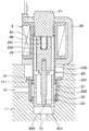
図1に示すように、ブレーキ用流体制御装置に相当するABSアクチュエータは、ハウジング1と電磁弁2とを備えている。
As shown in FIG. 1, an ABS actuator corresponding to a brake fluid control device includes a
図2に示すように、ハウジング1は、アルミニウム等の金属よりなり、ブレーキ液が流通する流体通路10と、電磁弁2のスリーブ20(詳細後述)が挿入される円柱状の組み付け穴11が形成されている。
As shown in FIG. 2, the
組み付け穴11は、流体通路10に連通するとともに、一端の開口部110がハウジング1の外部に開放されている。また、かしめ加工前は、組み付け穴11の底部111は、平坦な面になっている。
The
電磁弁2は、組み付け穴11に挿入されるスリーブ20を備えている。このスリーブ20は、ステンレス等の非磁性材をプレス成形したもので、円筒状のスリーブ本体部200と、スリーブ本体部200の一端側端部からスリーブ本体部200の径方向外側に突出する円板状のスリーブフランジ部201を備えている。このスリーブフランジ部201は、その周方向全域に渡って組み付け穴11の底部111に向かって凸形状になるように、換言すると断面形状が円弧状になるように、プレス曲げ加工されている。
The
図1に示すように、スリーブ本体部200におけるスリーブフランジ部201とは反対側の端部の内部には、磁性体金属にて形成された円柱状のステータコア21が配置されている。そして、スリーブ本体部200とステータコア21は、レーザ溶接等にて液密に接合され、これにより、スリーブ本体部200の端部が閉塞されている。
As shown in FIG. 1, a
スリーブ本体部200におけるスリーブフランジ部201側の端部の内部には、有底円筒状にプレス成形された金属製のバルブシート22がレーザ溶接等にて液密に接合されている。より詳細には、バルブシート22は、その開口側端部がスリーブ本体部200に溶接接合されている。
Inside the end portion of the sleeve
このバルブシート22の底部には、ハウジング1の流体通路10を連通させる弁座穴220と、この弁座穴220を囲む弁座221が形成され、後述する弁体が弁座221と接離して流体通路10が開閉されるようになっている。また、バルブシート22の側面には、ハウジング1の流体通路10を連通させる連通穴222が形成されている。
A
スリーブ20の内部には、磁性体金属にて形成された円柱状のプランジャ23が、往復動可能に挿入されている。このプランジャ23の外周面には、プランジャ23の一端側から他端側まで延びる溝部230が複数個形成されている。
A
プランジャ23には、ステータコア21側にばね挿入穴231が形成されており、このばね挿入穴231には、プランジャ23を弁座221側に向かって付勢するばね24が挿入されている。
A
プランジャ23におけるステータコア21とは反対側の端部には、円柱状の弁体25が、プランジャ23に設けた穴へ圧入されて固定されている。この弁体25は、プランジャ23と連動し、弁座221と接離して流体通路10を開閉する。
A
スリーブ20には、フィルタ27が装着されている。フィルタ27は連通穴222に対向する位置に配置されている。そして、フィルタ27により、ブレーキ液に混入した異物が電磁弁2内に入り込むことを防止するようになっている。
A
スリーブ20におけるハウジング1から突出した部位の外周には、通電時に磁界を形成するコイル28が配置されている。また、磁性体金属からなるヨーク29が、コイル28を囲むようにして配置されている。
A
スリーブ20、ステータコア21、バルブシート22、プランジャ23、ばね24、弁体25、およびフィルタ27が一体化されて弁部が構成され、この弁部がハウジング1に組み付けられた後に、コイル28およびヨーク29がスリーブ20に装着されるようになっている。尚、バルブシート22はハウジング1の穴へ液密に圧入固定される。
The
次に、上記構成になる電磁弁2の作動を説明する。図1はコイル非通電時の状態を示しており、コイル非通電時にはばね24の弾性力によってプランジャ23がバルブシート22側に向かって付勢され、弁体25が弁座221に着座して弁座穴220が閉じられ、これにより、流体通路10が遮断状態となってブレーキ液の流通が阻止される。
Next, the operation of the
一方、コイル通電時には、コイル28が磁界を形成し、ステータコア21、プランジャ23、およびヨーク29により磁路が形成される。そして、磁気吸引力によりプランジャ23がばね24の弾性力に抗してステータコア21側に吸引され、弁体25が弁座221から離れて弁座穴220が開かれ、これにより、流体通路10が連通状態となってブレーキ液が流通可能になる。
On the other hand, when the coil is energized, the
次に、弁部とハウジング1との固定、より詳細には、スリーブ20とハウジング1との固定について説明する。なお、図2および図3では、理解を容易にするために、スリーブ20以外の弁部構成部品の図示を省略している。
Next, fixing of the valve portion and the
まず、図2に示すように、スリーブ20を組み付け穴11に挿入し、スリーブフランジ部201を組み付け穴11の底部111に当接させる。
First, as shown in FIG. 2, the
次に、図3に示すように、ハウジング1における開口部110の周囲をかしめる。これにより、ハウジング1が塑性変形し、その塑性変形したかしめ変形部12と組み付け穴11の底部111との間にスリーブフランジ部201が挟持される。
Next, as shown in FIG. 3, the periphery of the
そして、スリーブフランジ部201における頂部と組み付け穴11の底部111との当接部A、およびスリーブフランジ部201における外周角部とかしめ変形部12との当接部Bには、高い面圧が発生し、良好なシール性が得られる。
High contact pressure is generated at the contact portion A between the top portion of the
本実施形態によると、当接部A、Bに高い面圧が発生するため、良好なシール性を得ることができる。また、曲げ加工によってスリーブフランジ部201を凸形状に形成するため、プレス成形による加工が容易である。さらに、スリーブフランジ部201の加工が容易であるため加工精度が安定し、その結果安定したシール性を得ることができる。
According to the present embodiment, a high surface pressure is generated at the contact portions A and B, so that good sealing performance can be obtained. In addition, since the
なお、上記実施形態においては、スリーブフランジ部201を、組み付け穴11の底部111に向かって凸形状になるようにプレス曲げ加工したが、図4、図5に示す変形例のように、スリーブフランジ部201は、組み付け穴11の底部111に向かって凹形状になるようにプレス曲げ加工してもよい。この場合、スリーブフランジ部201における頂部とかしめ変形部12との当接部C、およびスリーブフランジ部201における外周角部と組み付け穴11の底部111との当接部Dには、高い面圧が発生し、良好なシール性が得られる。
In the above embodiment, the
(第2実施形態)
本発明の第2実施形態について説明する。以下、第1実施形態と異なる部分についてのみ説明する。
(Second Embodiment)
A second embodiment of the present invention will be described. Only the parts different from the first embodiment will be described below.
ところで、第1実施形態に係るブレーキ用流体制御装置においては、スリーブフランジ部201における内周側の部位に、流体通路10のブレーキ液の圧力が作用する。そして、高いブレーキ液圧が作用した場合、スリーブフランジ部201が変形し、それに伴ってかしめ変形部12も塑性変形し、その結果、スリーブフランジ部201と組み付け穴11の底部111との当接部や、スリーブフランジ部201とかしめ変形部12との当接部の面圧が低下し、シール性が低下する虞がある。
By the way, in the brake fluid control apparatus according to the first embodiment, the pressure of the brake fluid in the
そこで本実施形態では、図6に示すように、スリーブフランジ部201とかしめ変形部12との間に、変形抑制部材としてのリング30を挟持している。リング30は、金属製で、剛性を高めるためにスリーブフランジ部201よりも板厚が十分大きく設定されている。また、リング30は、円板状に形成され、スリーブフランジ部201における外部空間側の面のほぼ全域に当接している。
Therefore, in the present embodiment, as shown in FIG. 6, a
そして、ブレーキ液圧によってスリーブフランジ部201に作用する荷重は、剛性の高いリング30にて受けられるため、スリーブフランジ部201の変形が防止ないしは抑制される。したがって、スリーブフランジ部201と組み付け穴11の底部111との当接部の面圧低下が防止ないしは抑制され、良好なシール性が維持される。
Since the load acting on the
本実施形態によると、第1実施形態と同様の効果を得ることができる。また、リング30にてスリーブフランジ部201の変形を防止ないしは抑制するため、良好なシール性を継続して得ることができる。
According to this embodiment, the same effect as that of the first embodiment can be obtained. Further, since the
(第3実施形態)
本発明の第3実施形態について説明する。以下、第1実施形態と異なる部分についてのみ説明する。
(Third embodiment)
A third embodiment of the present invention will be described. Only the parts different from the first embodiment will be described below.
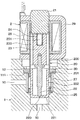
図7に示すように、バルブシート22は、その開口端部側からバルブシート22の径方向外側に突出する円板状のバルブシートフランジ部223を備えている。このバルブシートフランジ部223は、その周方向全域に渡って組み付け穴11の底部111に向かって凸形状になるように、換言すると断面形状が円弧状になるように、プレス曲げ加工されている。
As shown in FIG. 7, the
スリーブ20は、スリーブフランジ部201が廃止されている。そして、スリーブ20は、バルブシート22に圧入された後、溶接にてバルブシート22と接合されている。
The
次に、弁部とハウジング1との固定、より詳細には、バルブシート22とハウジング1との固定について説明する。まず、バルブシート22を組み付け穴11(図2参照)に挿入し、バルブシートフランジ部223を組み付け穴11の底部111に当接させる。
Next, fixing of the valve portion and the
次に、ハウジング1における開口部110(図2参照)の周囲をかしめる。これにより、ハウジング1が塑性変形し、その塑性変形したかしめ変形部12と組み付け穴11の底部111との間にバルブシートフランジ部223が挟持される。
Next, the periphery of the opening 110 (see FIG. 2) in the
そして、バルブシートフランジ部223における頂部と組み付け穴11の底部111との当接部、およびバルブシートフランジ部223における外周角部とかしめ変形部12との当接部には、高い面圧が発生し、良好なシール性が得られる。
High contact pressure is generated at the contact portion between the top portion of the valve
本実施形態によると、当接部に高い面圧が発生するため、良好なシール性を得ることができる。また、曲げ加工によってバルブシートフランジ部223を凸形状に形成するため、プレス成形による加工が容易である。さらに、バルブシートフランジ部223の加工が容易であるため加工精度が安定し、その結果安定したシール性を得ることができる。
According to this embodiment, since a high surface pressure is generated at the contact portion, a good sealing property can be obtained. Further, since the valve
なお、上記実施形態においては、バルブシートフランジ部223を、組み付け穴11の底部111に向かって凸形状になるようにプレス曲げ加工したが、バルブシートフランジ部223は、組み付け穴11の底部111に向かって凹形状になるようにプレス曲げ加工してもよい。この場合、バルブシートフランジ部223における頂部とかしめ変形部12との当接部、およびバルブシートフランジ部223における外周角部と組み付け穴11の底部111との当接部には、高い面圧が発生し、良好なシール性が得られる。
In the above embodiment, the valve
(第4実施形態)
本発明の第4実施形態について説明する。以下、第3実施形態と異なる部分についてのみ説明する。
(Fourth embodiment)
A fourth embodiment of the present invention will be described. Only the parts different from the third embodiment will be described below.
図8に示すように、バルブシートフランジ部223とかしめ変形部12との間に、変形抑制部材としてのリング30を挟持している。リング30は、金属製で、剛性を高めるためにバルブシートフランジ部223よりも板厚が十分大きく設定されている。また、リング30は、円板状に形成され、バルブシートフランジ部223における外部空間側の面のほぼ全域に当接している。
As shown in FIG. 8, a
そして、高いブレーキ液圧が作用した場合、バルブシートフランジ部223に作用する荷重は、剛性の高いリング30にて受けられるため、バルブシートフランジ部223の変形が防止ないしは抑制される。したがって、バルブシートフランジ部223と組み付け穴11の底部111との当接部の面圧低下が防止ないしは抑制され、良好なシール性が維持される。
When a high brake fluid pressure is applied, the load acting on the valve
本実施形態によると、第3実施形態と同様の効果を得ることができる。また、リング30にてバルブシートフランジ部223の変形を防止ないしは抑制するため、良好なシール性を継続して得ることができる。
According to this embodiment, the same effect as that of the third embodiment can be obtained. Further, since the
(他の実施形態)
なお、本発明は上記した実施形態に限定されるものではなく、特許請求の範囲に記載した範囲内において適宜変更が可能である。
(Other embodiments)
In addition, this invention is not limited to above-described embodiment, In the range described in the claim, it can change suitably.
また、上記各実施形態は、互いに無関係なものではなく、組み合わせが明らかに不可な場合を除き、適宜組み合わせが可能である。 Further, the above embodiments are not irrelevant to each other, and can be combined as appropriate unless the combination is clearly impossible.
また、上記各実施形態において、実施形態を構成する要素は、特に必須であると明示した場合および原理的に明らかに必須であると考えられる場合等を除き、必ずしも必須のものではないことは言うまでもない。 In each of the above-described embodiments, it is needless to say that elements constituting the embodiment are not necessarily essential unless explicitly stated as essential and clearly considered essential in principle. Yes.
また、上記各実施形態において、実施形態の構成要素の個数、数値、量、範囲等の数値が言及されている場合、特に必須であると明示した場合および原理的に明らかに特定の数に限定される場合等を除き、その特定の数に限定されるものではない。 Further, in each of the above embodiments, when numerical values such as the number, numerical value, quantity, range, etc. of the constituent elements of the embodiment are mentioned, it is clearly limited to a specific number when clearly indicated as essential and in principle. The number is not limited to the specific number except for the case.
また、上記各実施形態において、構成要素等の形状、位置関係等に言及するときは、特に明示した場合および原理的に特定の形状、位置関係等に限定される場合等を除き、その形状、位置関係等に限定されるものではない。 Further, in each of the above embodiments, when referring to the shape, positional relationship, etc. of the component, etc., the shape, unless otherwise specified and in principle limited to a specific shape, positional relationship, etc. It is not limited to the positional relationship or the like.
1 ハウジング
2 電磁弁
10 流体通路
11 組み付け穴
12 かしめ変形部
20 スリーブ
23 プランジャ
25 弁体
28 コイル
110 開口部
111 底部
201 スリーブフランジ部(フランジ部)
DESCRIPTION OF
Claims (3)
前記ハウジングは、
ブレーキ液が流通する流体通路(10)と、
一端の開口部(110)が前記ハウジングの外部に開放されるともに、平坦な底部(111)が形成された組み付け穴(11)とを備え、
前記電磁弁は、
前記組み付け穴に一端側が挿入される円筒状のスリーブ(20)と、
前記スリーブの他端側外周に配置されたコイル(28)と、
前記スリーブ内に収容され、前記コイルへの通電状態に応じて前記スリーブ内を移動するプランジャ(23)と、
プランジャと連動して前記流体通路を開閉する弁体(25)とを備え、
前記スリーブは、前記スリーブの一端側端部から前記スリーブの径方向外側に突出する円板状のフランジ部(201)を備え、
前記フランジ部は、曲げ加工によって、その周方向全域に渡って前記組み付け穴の底部に向かって凸形状または凹形状になるように形成され、
前記フランジ部は前記組み付け穴内に配置され、
前記組み付け穴の開口部周囲がかしめられることによって、かしめによって変形したかしめ変形部(12)と前記組み付け穴の底部との間に前記フランジ部が挟持されていることを特徴とするブレーキ用流体制御装置。 A housing (1) and a solenoid valve (2);
The housing is
A fluid passage (10) through which brake fluid flows;
An opening (110) at one end is opened to the outside of the housing, and an assembly hole (11) having a flat bottom (111) is formed,
The solenoid valve is
A cylindrical sleeve (20) having one end inserted into the assembly hole;
A coil (28) disposed on the outer periphery of the other end of the sleeve;
A plunger (23) housed in the sleeve and moving in the sleeve in accordance with the energization state of the coil;
A valve body (25) that opens and closes the fluid passage in conjunction with a plunger,
The sleeve includes a disc-shaped flange portion (201) that protrudes radially outward of the sleeve from one end of the sleeve.
The flange portion is formed to be a convex shape or a concave shape toward the bottom of the assembly hole over the entire circumferential direction by bending,
The flange portion is disposed in the assembly hole,
Brake fluid control, wherein the flange portion is sandwiched between a caulking deformed portion (12) deformed by caulking and a bottom portion of the assembling hole by caulking around the opening portion of the assembling hole. apparatus.
前記ハウジングは、
ブレーキ液が流通する流体通路(10)と、
一端の開口部(110)が前記ハウジングの外部に開放されるともに、平坦な底部(111)が形成された組み付け穴(11)とを備え、
前記電磁弁は、
前記組み付け穴に一端側が挿入されるとともに底部に弁座(221)が形成された有底円筒状のバルブシート(22)と、
前記バルブシートに挿入される円筒状のスリーブ(20)と、
前記スリーブの他端側外周に配置されたコイル(28)と、
前記スリーブ内に収容され、前記コイルへの通電状態に応じて前記スリーブ内を移動するプランジャ(23)と、
プランジャと連動して前記弁座と接離することにより前記流体通路を開閉する弁体(25)とを備え、
前記バルブシートは、前記バルブシートの一端側端部から前記バルブシートの径方向外側に突出する円板状のフランジ部(223)を備え、
前記フランジ部は、曲げ加工によって、その周方向全域に渡って前記組み付け穴の底部に向かって凸形状または凹形状になるように形成され、
前記フランジ部は前記組み付け穴内に配置され、
前記組み付け穴の開口部周囲がかしめられることによって、かしめによって変形したかしめ変形部(12)と前記組み付け穴の底部との間に前記フランジ部が挟持されていることを特徴とするブレーキ用流体制御装置。 A housing (1) and a solenoid valve (2);
The housing is
A fluid passage (10) through which brake fluid flows;
An opening (110) at one end is opened to the outside of the housing, and an assembly hole (11) having a flat bottom (111) is formed,
The solenoid valve is
A bottomed cylindrical valve seat (22) in which one end side is inserted into the assembly hole and a valve seat (221) is formed at the bottom;
A cylindrical sleeve (20) inserted into the valve seat;
A coil (28) disposed on the outer periphery of the other end of the sleeve;
A plunger (23) housed in the sleeve and moving in the sleeve in accordance with the energization state of the coil;
A valve body (25) for opening and closing the fluid passage by contacting and separating from the valve seat in conjunction with a plunger;
The valve seat includes a disk-like flange portion (223) that protrudes radially outward of the valve seat from one end of the valve seat.
The flange portion is formed to be a convex shape or a concave shape toward the bottom of the assembly hole over the entire circumferential direction by bending,
The flange portion is disposed in the assembly hole,
Brake fluid control, wherein the flange portion is sandwiched between a caulking deformed portion (12) deformed by caulking and a bottom portion of the assembling hole by caulking around the opening portion of the assembling hole. apparatus.
Priority Applications (4)
| Application Number | Priority Date | Filing Date | Title |
|---|---|---|---|
| JP2014142493A JP2016016828A (en) | 2014-07-10 | 2014-07-10 | Brake fluid controller |
| US14/750,134 US20160009266A1 (en) | 2014-07-10 | 2015-06-25 | Braking fluid control apparatus |
| DE102015110918.2A DE102015110918A1 (en) | 2014-07-10 | 2015-07-07 | Brake fluid control apparatus |
| CN201510398459.6A CN105253130A (en) | 2014-07-10 | 2015-07-08 | Braking fluid control apparatus |
Applications Claiming Priority (1)
| Application Number | Priority Date | Filing Date | Title |
|---|---|---|---|
| JP2014142493A JP2016016828A (en) | 2014-07-10 | 2014-07-10 | Brake fluid controller |
Publications (1)
| Publication Number | Publication Date |
|---|---|
| JP2016016828A true JP2016016828A (en) | 2016-02-01 |
Family
ID=54867082
Family Applications (1)
| Application Number | Title | Priority Date | Filing Date |
|---|---|---|---|
| JP2014142493A Pending JP2016016828A (en) | 2014-07-10 | 2014-07-10 | Brake fluid controller |
Country Status (4)
| Country | Link |
|---|---|
| US (1) | US20160009266A1 (en) |
| JP (1) | JP2016016828A (en) |
| CN (1) | CN105253130A (en) |
| DE (1) | DE102015110918A1 (en) |
Families Citing this family (5)
| Publication number | Priority date | Publication date | Assignee | Title |
|---|---|---|---|---|
| JP6347444B2 (en) * | 2014-09-12 | 2018-06-27 | 日立オートモティブシステムズ株式会社 | solenoid valve |
| DE102016215745A1 (en) * | 2016-08-23 | 2018-03-01 | Robert Bosch Gmbh | Electromagnetically operated suction valve and method for producing an electromagnetically actuated suction valve |
| CA3039592A1 (en) * | 2016-09-07 | 2018-03-15 | Tokenize, Inc. | System and method for supplying security information |
| US11320061B2 (en) * | 2017-11-22 | 2022-05-03 | Eagle Industry Co., Ltd. | Solenoid valve |
| CN112406827A (en) * | 2020-10-28 | 2021-02-26 | 东科克诺尔商用车制动技术有限公司 | Valve core assembly of automobile air brake ABS electromagnetic valve |
Citations (7)
| Publication number | Priority date | Publication date | Assignee | Title |
|---|---|---|---|---|
| JPH0914500A (en) * | 1995-06-23 | 1997-01-14 | Toyota Motor Corp | Solenoid valve assembling structure |
| JP2000142351A (en) * | 1998-11-02 | 2000-05-23 | Denso Corp | Assembly structure of solenoid valve in abs actuator |
| JP3094136U (en) * | 2002-11-19 | 2003-06-06 | 日清紡績株式会社 | solenoid valve |
| US6742764B1 (en) * | 1999-08-25 | 2004-06-01 | Continental Teves Ag & Co., Ohg | Electromagnetic valve |
| JP2008019919A (en) * | 2006-07-11 | 2008-01-31 | Hitachi Ltd | Solenoid valve |
| JP2011064270A (en) * | 2009-09-17 | 2011-03-31 | Advics Co Ltd | Hydraulic device with solenoid valve |
| JP2012162118A (en) * | 2011-02-04 | 2012-08-30 | Hitachi Automotive Systems Ltd | Brake device |
Family Cites Families (12)
| Publication number | Priority date | Publication date | Assignee | Title |
|---|---|---|---|---|
| US4030668A (en) * | 1976-06-17 | 1977-06-21 | The Bendix Corporation | Electromagnetically operated fuel injection valve |
| JPH04147645A (en) | 1990-10-09 | 1992-05-21 | Dainippon Printing Co Ltd | Semiconductor integrated circuit device |
| JP3613628B2 (en) * | 1996-01-12 | 2005-01-26 | 日清紡績株式会社 | Solenoid valve device |
| US6644623B1 (en) * | 1999-06-23 | 2003-11-11 | Continental Teves Ag & Co. Ohg | Electromagnetic valve |
| JP2001208233A (en) * | 2000-01-31 | 2001-08-03 | Aisin Seiki Co Ltd | Solenoid valve |
| US6546945B2 (en) * | 2000-06-29 | 2003-04-15 | Denso Corporation | Electromagnetic valve |
| US20060017033A1 (en) * | 2002-12-13 | 2006-01-26 | Christoph Voss | Electromagnetic valve |
| JP4432681B2 (en) * | 2003-10-06 | 2010-03-17 | 株式会社アドヴィックス | Brake fluid control system |
| DE102005044672A1 (en) * | 2005-09-19 | 2007-03-22 | Robert Bosch Gmbh | magnetic valve |
| KR20100003784A (en) * | 2008-07-02 | 2010-01-12 | 주식회사 만도 | Solenoid valve for brake system and manufacturing method thereof |
| JP5563391B2 (en) * | 2010-07-05 | 2014-07-30 | 株式会社日本自動車部品総合研究所 | solenoid valve |
| JP6136290B2 (en) | 2013-01-24 | 2017-05-31 | 大日本印刷株式会社 | Electronic book display device, electronic book display method, and electronic book display program |
-
2014
- 2014-07-10 JP JP2014142493A patent/JP2016016828A/en active Pending
-
2015
- 2015-06-25 US US14/750,134 patent/US20160009266A1/en not_active Abandoned
- 2015-07-07 DE DE102015110918.2A patent/DE102015110918A1/en not_active Withdrawn
- 2015-07-08 CN CN201510398459.6A patent/CN105253130A/en active Pending
Patent Citations (7)
| Publication number | Priority date | Publication date | Assignee | Title |
|---|---|---|---|---|
| JPH0914500A (en) * | 1995-06-23 | 1997-01-14 | Toyota Motor Corp | Solenoid valve assembling structure |
| JP2000142351A (en) * | 1998-11-02 | 2000-05-23 | Denso Corp | Assembly structure of solenoid valve in abs actuator |
| US6742764B1 (en) * | 1999-08-25 | 2004-06-01 | Continental Teves Ag & Co., Ohg | Electromagnetic valve |
| JP3094136U (en) * | 2002-11-19 | 2003-06-06 | 日清紡績株式会社 | solenoid valve |
| JP2008019919A (en) * | 2006-07-11 | 2008-01-31 | Hitachi Ltd | Solenoid valve |
| JP2011064270A (en) * | 2009-09-17 | 2011-03-31 | Advics Co Ltd | Hydraulic device with solenoid valve |
| JP2012162118A (en) * | 2011-02-04 | 2012-08-30 | Hitachi Automotive Systems Ltd | Brake device |
Also Published As
| Publication number | Publication date |
|---|---|
| DE102015110918A1 (en) | 2016-01-14 |
| CN105253130A (en) | 2016-01-20 |
| US20160009266A1 (en) | 2016-01-14 |
Similar Documents
| Publication | Publication Date | Title |
|---|---|---|
| JP2016016828A (en) | Brake fluid controller | |
| JP4432681B2 (en) | Brake fluid control system | |
| JP6347444B2 (en) | solenoid valve | |
| CN108150695B (en) | Electromagnetic actuating mechanism, magnetic flux disk body for an electromagnetic actuating mechanism, and method for producing an electromagnetic actuating mechanism | |
| JP6200695B2 (en) | Oil immersed solenoid | |
| JP6701823B2 (en) | Solenoid valve device | |
| KR102275772B1 (en) | Electromagnetic actuating device | |
| CN111480024A (en) | Electromagnetic valve | |
| JP2005014701A (en) | Fluid controlling device | |
| JP5487836B2 (en) | Hydraulic device with solenoid valve | |
| JP6743631B2 (en) | Solenoid valve device | |
| JP4038452B2 (en) | Proportional solenoid valve | |
| US7975982B2 (en) | Electromagnetic valve | |
| JP2019086086A (en) | Valve device and assembly method of the same | |
| JP5891733B2 (en) | solenoid valve | |
| JP6308685B2 (en) | Energized closed solenoid valve manufacturing method and energized closed solenoid valve | |
| JP6287671B2 (en) | solenoid valve | |
| JP4597027B2 (en) | solenoid valve | |
| JP2013212531A (en) | Caulking joint method and caulking joint structure | |
| JP7121694B2 (en) | solenoid valve | |
| EP1647460A1 (en) | Solenoid valve for brake system | |
| JP5412330B2 (en) | hydraulic unit | |
| JP6118039B2 (en) | Brake fluid pressure control device and manufacturing method thereof. | |
| JP4251032B2 (en) | Fluid control device | |
| JP2013108573A (en) | Solenoid valve |
Legal Events
| Date | Code | Title | Description |
|---|---|---|---|
| A711 | Notification of change in applicant |
Free format text: JAPANESE INTERMEDIATE CODE: A711 Effective date: 20160426 |
|
| A621 | Written request for application examination |
Free format text: JAPANESE INTERMEDIATE CODE: A621 Effective date: 20160513 |
|
| RD04 | Notification of resignation of power of attorney |
Free format text: JAPANESE INTERMEDIATE CODE: A7424 Effective date: 20160623 |
|
| A977 | Report on retrieval |
Free format text: JAPANESE INTERMEDIATE CODE: A971007 Effective date: 20170222 |
|
| A131 | Notification of reasons for refusal |
Free format text: JAPANESE INTERMEDIATE CODE: A131 Effective date: 20170228 |
|
| A02 | Decision of refusal |
Free format text: JAPANESE INTERMEDIATE CODE: A02 Effective date: 20170829 |