JP2016014496A - Refrigeration system - Google Patents
Refrigeration system Download PDFInfo
- Publication number
- JP2016014496A JP2016014496A JP2014136394A JP2014136394A JP2016014496A JP 2016014496 A JP2016014496 A JP 2016014496A JP 2014136394 A JP2014136394 A JP 2014136394A JP 2014136394 A JP2014136394 A JP 2014136394A JP 2016014496 A JP2016014496 A JP 2016014496A
- Authority
- JP
- Japan
- Prior art keywords
- air
- cold water
- heat exchanger
- conditioning
- refrigeration
- Prior art date
- Legal status (The legal status is an assumption and is not a legal conclusion. Google has not performed a legal analysis and makes no representation as to the accuracy of the status listed.)
- Granted
Links
Images


Abstract
Description
本発明は、冷凍システムに係り、特に、排熱利用の冷温水機の冷水を利用することにより、二酸化炭素冷媒を用いた空冷冷凍機の消費電力を低減させることができ、季節に応じて効率のよい動作を行うことを可能とした冷凍システムに関するものである。 The present invention relates to a refrigeration system, and in particular, by using the chilled water of a chiller / heater using exhaust heat, the power consumption of an air-cooled chiller using a carbon dioxide refrigerant can be reduced, and the efficiency is improved according to the season. The present invention relates to a refrigeration system that can perform a good operation.
従来から、低温ショーケースなどを冷却するための冷凍システムとして、圧縮機、放熱器、減圧器および蒸発器からなる蒸気圧縮式冷凍サイクルを利用した冷凍システムが広く利用されている。このような冷凍システムにおいては、蒸気圧縮式冷凍サイクルの蒸発器における冷媒の蒸発により食品などを冷却して冷凍、冷蔵するものである。
しかし、一般に広く利用されている冷凍システムにおいては、冷凍サイクルからの冷却廃熱は放熱器から大気などに捨てられている。その一方で、同一施設内で利用するお湯をボイラーなどにより別の熱源を利用して供給することが行われている。このように、従来から広く利用されている冷凍システムでは、冷却廃熱が有効に利用されていないという問題があった。
Conventionally, as a refrigeration system for cooling a low-temperature showcase or the like, a refrigeration system using a vapor compression refrigeration cycle including a compressor, a radiator, a decompressor, and an evaporator has been widely used. In such a refrigeration system, food and the like are cooled and frozen and refrigerated by evaporation of refrigerant in an evaporator of a vapor compression refrigeration cycle.
However, in a widely used refrigeration system, the cooling waste heat from the refrigeration cycle is discarded from the radiator to the atmosphere. On the other hand, hot water used in the same facility is supplied by using a different heat source with a boiler or the like. As described above, the refrigeration system that has been widely used conventionally has a problem that the cooling waste heat is not effectively used.
そのため、このような冷凍システムにおいて、冷却排熱を有効に利用するシステムとして、従来、例えば、第一の冷凍サイクル回路に、第一放熱器で冷却された後の冷媒を過冷却する過冷却器を設け、過冷却器において第一の冷凍サイクル回路とは別の第二の冷凍サイクル回路の冷媒の蒸発作用により第一の冷凍サイクル回路の冷媒を過冷却するとともに、第二の冷凍サイクル回路の第二放熱器における冷媒の放熱作用により給湯水を加温するようにした技術が開示されている(例えば、特許文献1参照)。 Therefore, in such a refrigeration system, as a system that effectively uses cooling exhaust heat, conventionally, for example, a supercooler that supercools the refrigerant after being cooled by the first radiator in the first refrigeration cycle circuit In the subcooler, the refrigerant in the first refrigeration cycle circuit is supercooled by the evaporation of the refrigerant in the second refrigeration cycle circuit different from the first refrigeration cycle circuit, and the second refrigeration cycle circuit A technique is disclosed in which hot water is heated by the heat radiation action of the refrigerant in the second radiator (see, for example, Patent Document 1).
前記特許文献1に記載の発明は、第二の冷凍サイクル回路の冷媒の蒸発作用により第一の冷凍サイクル回路の冷媒を過冷却することにより、冷却排熱を有効に利用するものである。
一方、近年、二酸化炭素冷媒を用いた空冷冷凍機の改良が進んでおり、従来のHFC冷媒を用いた冷凍機と比較して冷凍領域および冷蔵領域おいて、年間の消費電力は少なくなってきている。
しかしながら、二酸化炭素冷媒を用いた空冷冷凍機は、冷蔵領域において、夏季など高外気温時に、HFC冷媒を用いた冷凍機に比べて消費電力が大きくなる領域があり、猛暑時にピーク電力を押し上げるおそれがあるため、消費電力の増加を招いてしまうという問題を有している。
The invention described in
On the other hand, in recent years, improvement of air-cooled refrigerators using carbon dioxide refrigerant has progressed, and annual power consumption has decreased in the refrigeration area and refrigeration area compared to conventional refrigerators using HFC refrigerant. Yes.
However, air-cooled refrigerators that use carbon dioxide refrigerant have a region that consumes more power than refrigerators that use HFC refrigerant in refrigerated regions at high outside temperatures, such as in summer, and may increase peak power during extreme heat. Therefore, there is a problem that power consumption is increased.
本発明は前記した点に鑑みてなされたものであり、二酸化炭素冷媒を用いた空冷冷凍機の消費電力を低減させることができ、季節に応じて効率のよい動作を行うことができる冷凍システムを提供することを目的としている。 The present invention has been made in view of the above points, and provides a refrigeration system that can reduce the power consumption of an air-cooled refrigerator using a carbon dioxide refrigerant and can perform an efficient operation according to the season. It is intended to provide.
前記目的を達成するために、本発明に係る冷凍システムは、空冷式ガスクーラを備え二酸化炭素冷媒を用いた冷凍機を構成する冷凍サイクル回路と、冷温水機の冷水により空調を行う空調回路と、を備え、前記冷凍サイクル回路は、前記冷温水機の冷水を利用して前記ガスクーラから出た冷媒の過冷却を行う過冷却熱交換器を備えていることを特徴とする。 In order to achieve the above object, a refrigeration system according to the present invention includes a refrigeration cycle circuit that constitutes a chiller that includes an air-cooled gas cooler and that uses a carbon dioxide refrigerant, an air-conditioning circuit that performs air-conditioning with the cold water of a hot and cold water machine, The refrigeration cycle circuit includes a supercooling heat exchanger that performs supercooling of the refrigerant discharged from the gas cooler using the cold water of the cold / hot water machine.
本発明は、前記構成において、前記空調回路は、前記冷温水機からの冷水を空調系統に送る空調用往き配管を備え、前記空調用往き配管から分岐した冷水用往き配管を介して前記過冷却熱交換器に冷水を送ることを特徴とする。 According to the present invention, in the above configuration, the air conditioning circuit includes an air conditioning forward pipe that sends cold water from the cold / hot water machine to an air conditioning system, and the supercooling is performed via the cold water forward pipe branched from the air conditioning forward pipe. It is characterized by sending cold water to the heat exchanger.
本発明は、前記構成において、前記空調回路は、空調系統からの冷水を前記冷温水機に戻す空調用戻り配管を備え、前記空調用戻り配管から分岐した冷水用往き配管を介して前記過冷却熱交換器に冷水を送ることを特徴とする。 According to the present invention, in the above configuration, the air conditioning circuit includes an air conditioning return pipe that returns the cold water from the air conditioning system to the cold / hot water machine, and the supercooling is performed via the cold water forward pipe branched from the air conditioning return pipe. It is characterized by sending cold water to the heat exchanger.
本発明は、前記構成において、前記冷温水機は、駆動熱源として燃料や蒸気や排熱を利用した冷温水機であることを特徴とする。 The present invention is characterized in that, in the above configuration, the cold / hot water machine is a cold / hot water machine using fuel, steam or exhaust heat as a drive heat source.
本発明は、前記構成において、前記排熱として、コジェネレーションの排熱または自然エネルギから得られる熱を利用したものであることを特徴とする。 The present invention is characterized in that, in the above configuration, as the exhaust heat, heat generated from cogeneration exhaust heat or natural energy is used.
本発明は、前記構成において、前記空調回による空調運転が不要な場合に、前記空調用往き配管の冷水の流れを遮断する手段を備えていることを特徴とする。 The present invention is characterized in that, in the above-described configuration, when the air-conditioning operation by the air-conditioning operation is unnecessary, the present invention includes means for blocking the flow of cold water in the air-conditioning forward pipe.
本発明は、前記構成において、前記過冷却熱交換器による過冷却が不要な場合に、前記冷水用往き配管の冷水の流れを遮断する手段を備えていることを特徴とする。 The present invention is characterized in that, in the configuration described above, when the supercooling by the supercooling heat exchanger is unnecessary, the present invention is provided with means for blocking the flow of the cold water in the cold water outgoing pipe.
本発明は、前記構成において、状態急変による全体システムの発停や異常停止防止のため、前記過冷却熱交換器に冷水を供給開始する、あるいは停止する際に、前記過冷却熱交換器に送られる冷水の流量を徐々に増やす、あるいは徐々に減らすように制御する制御手段を備えていることを特徴とする。 According to the present invention, in the configuration described above, in order to prevent the entire system from being stopped or stopped due to a sudden change in state, or to stop abnormal cooling, supply of cold water to the supercooling heat exchanger is started or stopped. It is characterized by comprising control means for controlling the flow rate of the cold water to be gradually increased or decreased.
本発明は、前記構成において、前記過冷却熱交換器は、前記冷凍機の前記ガスクーラの配置空間の底部に配置されるものであることを特徴とする。 The present invention is characterized in that, in the above-mentioned configuration, the supercooling heat exchanger is disposed at a bottom portion of a space where the gas cooler of the refrigerator is disposed.
本発明によれば、冷凍サイクル回路にガスクーラから出た冷媒の過冷却を行う過冷却熱交換器を設け、過冷却熱交換器により冷温水機の冷水を利用して冷凍機における冷媒の過冷却を行うようにしているので、冷凍機により効率よくショーケースの冷凍または冷蔵を行うことが可能となる。その結果、省電力化を図ることができ、契約電力を大幅に低減させることができる。 According to the present invention, the refrigeration cycle circuit is provided with a supercooling heat exchanger that supercools the refrigerant discharged from the gas cooler, and the supercooling of the refrigerant in the refrigeration machine is performed using the cold water of the chilled water heater by the supercooling heat exchanger. Therefore, the showcase can be efficiently frozen or refrigerated by the refrigerator. As a result, power saving can be achieved, and contract power can be greatly reduced.
以下、本発明の実施形態について図面を参照して説明する。 Embodiments of the present invention will be described below with reference to the drawings.
図1は、本発明に係る冷凍システムの実施形態を示したものであり、本実施形態においては、冷凍システムは、例えば、ショッピングモールなどの店舗における冷却設備と空調設備の両者を備えた施設に設置される場合の例を示している。本実施形態の冷凍システムは、店舗内に設置される各ショーケース2を冷却する冷凍サイクル回路10と、この冷凍サイクル回路10に冷水を供給する空調回路30とを備えている。
FIG. 1 shows an embodiment of a refrigeration system according to the present invention. In this embodiment, the refrigeration system is installed in a facility having both cooling equipment and air conditioning equipment in a store such as a shopping mall. An example of installation is shown. The refrigeration system of this embodiment includes a
冷凍サイクル回路10は、冷凍機11およびショーケース2のシステムを構成するものであり、冷凍用圧縮機12、ガスクーラ13、過冷却熱交換器14および冷凍用蒸発器15を、順次、冷凍用冷媒配管16で接続して構成されている。本実施形態においては、冷凍用圧縮機12、ガスクーラ13および過冷却熱交換器14が、冷凍機11に配置され、冷凍用蒸発器15がショーケース2に配置されている。冷凍機11の上部には、送風ファン17が設置されている。
The
なお、一般に、冷凍機11は、その内部に仕切り板18を備えており、この仕切り板18の下方が冷凍用圧縮機12などの機械を収容する機械室19とされ、仕切り板18の上方がガスクーラ13などを配置する空間である熱交換器室20とされるものである。そして、ガスクーラ13は熱交換器室20の外面に設置されるものであり、送風ファン17を動作させることにより、ガスクーラ13を通って外気を取り入れ、熱交換器室20の上部から外部に排出するものである。
このようにガスクーラ13を通る外気の流れを確保するため、熱交換器室20の底部に設けた仕切り板18の中央部分は、比較的空間が確保されている。そこで、過冷却熱交換器14をこの仕切り板18の中央付近に配置することにより、従来の冷凍機11に対して容易に過冷却熱交換器14を設置することが可能となる。
In general, the
Thus, in order to ensure the flow of outside air through the
そして、冷凍用圧縮機12により圧縮された高温高圧冷媒は、ガスクーラ13において、送風ファン17により冷凍機11内を流れる外気と熱交換して冷却されるものであるが、二酸化炭素冷媒は、外気温度が二酸化炭素の臨界点より高い場合はガスクーラ13では凝縮せず、超臨界状態まま送りだされる。この冷媒は、過冷却熱交換器14において、空調回路30から送られる冷水と熱交換して冷却されて液冷媒となり、ショーケース2の冷凍用蒸発器15において庫内空気と熱交換することにより、ショーケース2の冷却を行うように構成されている。一方、過冷却熱交換器14の冷水は、冷媒と熱交換することにより加熱される。図1では、冷凍サイクル回路10は一組を表しているが、複数組を並列設置して過冷却用冷水を各組に並列に循環させることも可能である。
The high-temperature and high-pressure refrigerant compressed by the
次に、空調回路30は、水循環式の空気調和装置31を構成するものであり、この空気調和装置31は、例えば、排温水、排蒸気、排ガスなどの排熱源50を利用した冷温水機32を備えている。排熱源50としては、例えば、ガスエンジン排熱、ガスタービン排熱や燃料電池排熱などのコジェネレーション熱源の排熱や、ガスヒートポンプ排熱、または、太陽熱などの自然エネルギの熱など、種々の熱源が考えられる。
Next, the
冷温水機32には、冷水を図示しない空調系統に送る空調用往き配管33と、空調系統で所定の空調を行った後の冷水を冷温水機32に戻す空調用戻り配管34とがそれぞれ接続されている。空調用往き配管33の中途部には、空調用ポンプ35が設けられており、空調用往き配管33の空調用ポンプ35の下流側には、空調用往き配管33から分岐して過冷却熱交換器14の入口側に接続される冷水用往き配管36が設けられている。
過冷却熱交換器14の出口側には、空調用戻り配管34の中途部に接続される冷水用戻り配管37が設けられている。空調用往き配管33の中途部には、空調用開閉弁38が設けられており、冷水用往き配管36の中途部には、冷水用開閉弁39が設けられている。
Connected to the chiller /
On the outlet side of the
空気調和装置31は、排熱を利用した暖房用熱交換器40を備えており、暖房用熱交換器40には、空調用往き配管33の中途部に接続され温水を空調用往き配管33に送る暖房用往き配管41と、空調用戻り配管34の中途部から分岐され空調系統で所定の空調を行った後の温水を暖房用熱交換器40に戻す暖房用戻り配管42とがそれぞれ接続されている。暖房用戻り配管42の中途部には、暖房用開閉弁43が設けられている。
The
また、排熱源50には、排温水などの排熱源50を循環させる排熱源用配管51が設けられており、排熱源用配管51の中途部には、排熱源用ポンプ52が設けられている。排熱源用配管51の中途部には、冷温水機32および暖房用熱交換器40に排熱源50の温水を供給するための排熱源供給配管53がそれぞれ接続されており、排熱源用配管51の中途部には、冷温水機32および暖房用熱交換器40から排熱源50に温水を戻すための排熱源戻り配管54がそれぞれ冷温水用三方弁55および暖房用三方弁56を介して接続されている。
The
さらに、本実施形態においては、冷水用開閉弁39、空調用開閉弁38、暖房用開閉弁43、冷温水用三方弁55および暖房用三方弁56の切換制御や、冷温水機32、空調用ポンプ35、排熱源用ポンプ52、送風ファン17の駆動制御などを行うための制御手段としての第1コントローラ60が設けられている。また、外気温センサ61、冷凍機11のガスクーラ13の圧力を検出する圧力センサ62、ガスクーラ13を出る冷媒の温度を検出する冷媒温度センサ63などの検出値およびショーケース2の庫内温度の検出値を第1コントローラ60に送る第2コントローラ64が設けられている。そして、第1コントローラ60は、第2コントローラ64から送られる各種検出値に基づいて、各種制御を行うように構成されている。
Furthermore, in this embodiment, switching control of the cold water on-off
例えば、第1コントローラ60は、冬季など過冷却熱交換器14を使用しない場合は、冷水用開閉弁39を閉に制御するものであり、また、空気調和装置31の暖房運転時には、暖房用開閉弁43および暖房用三方弁56をそれぞれ開[熱交換器に通水するよう]に制御するものである。さらに、第1コントローラ60は、冬季暖房運転時に温熱源が安定して十分ある場合は、冷温水機用三方弁55を閉[冷温水機に通水しないよう]に制御して、暖房用熱交換器40のみにより暖房を行うようにしてもよい。
For example, the
また、第1コントローラ60は、空気調和装置31による暖房が不要な場合は、空調用開閉弁38、暖房用開閉弁43および暖房用三方弁56を閉に制御するものである。さらに、本実施形態においては、第1コントローラ60は、システム全体の総合消費電力を監視しながら、総消費合電力が目標値以下となるように過冷却用の冷水温度や冷水流量を制御するようになっている。
また、第1コントローラ60は、夏季など外気温が高温の場合において、過冷却熱交換器14に冷水を供給する場合は、冷凍機11の運転状態の急変を防止するため、冷水用開閉弁39を徐々に開くように制御することで、過冷却熱交換器14に送られる冷水の量を徐々に増やすように制御するものである。
The
In addition, when the outside air temperature is high, such as in summer, when the
次に、冷温水機32の構成について図2を参照して説明する。
冷温水機32としては、例えば、排熱投入型(直火式または蒸気式または排ガス式)吸収冷温水機、高温水・低温水吸収冷温水機、排熱駆動吸着式冷温水機など種々適用することが可能であるが、本実施形態においては、排熱投入型直火式吸収冷温水機を用いた場合について説明する。
Next, the structure of the cold /
As the chiller /
排熱投入型直火式吸収冷温水機32は、高温再生器70と、低温再生器71と、排熱再生器72と、凝縮器73と、蒸発器74と、吸収器75とを備えている。本実施形態においては、低温再生器71と、排熱再生器72と、凝縮器73とは、一体の容器に収納されており、蒸発器74と、吸収器75とは一体の容器に収納されている。
The waste heat input type direct fire absorption chiller /
高温再生器70は、バーナ76を燃焼させることにより、排熱再生器72から稀中間液配管77を介して送られる稀中間吸収液を加熱することで、冷媒蒸気を稀中間吸収液から分離させるものであり、冷媒蒸気は、冷媒蒸気配管78を介して低温再生器71に送られるようになっている。稀中間吸収液は、バーナ76による加熱により濃縮され、濃中間吸収液となる。なお、吸収液は、例えば、臭化リチウム(LiBr)水溶液(界面活性剤を含む)などで構成されるものである。
The
排熱再生器72は、吸収器75から稀吸収液配管79を介して送られる稀吸収液を稀吸収液散布装置80から散布させ、この稀吸収液を温熱源から送られる排温水により加熱して稀中間吸収液とするものである。稀中間吸収液は、稀中間液配管77を介して高温再生器70に送られるように構成されている。
また、低温再生器71には、稀中間液配管77の途中から分岐する稀中間液分岐配管81から稀中間吸収液が送られるように構成されており、低温再生器71にて、稀中間吸収液は、高温再生器70から送られる冷媒蒸気と熱交換し濃吸収液となる。この濃吸収液は、高温再生器70から出て稀中間吸収液と熱交換した濃中間吸収液と混合されて、濃吸収液配管82を介して吸収器75の上部に設置された濃吸収液散布装置83から散布されるように構成されている。一方、低温再生器71により、冷媒蒸気は、冷媒液となり、冷媒ドレン配管84を介して、稀吸収液配管79から分岐した稀吸収液分岐配管85と熱交換して凝縮器73に送られるように構成されている。
The
The
凝縮器73には、冷却水配管86が挿通されており、凝縮器73の内部の冷媒蒸気は、冷却水配管86を通る冷却水と熱交換して凝縮して冷媒液となる。冷媒液は、冷媒液配管87を介して蒸発器74に送られる。
A cooling
蒸発器74には、冷温水配管88(図1における空調用往き配管33および空調用戻り配管34に相当)が挿通されており、蒸発器74は、冷媒ポンプ89により、蒸発器74の下部に貯留された冷媒液を蒸発器74の上部に設置された冷媒散布装置90から散布するように構成されている。冷温水配管88を流れる冷温水は、冷媒散布装置90から散布された冷媒液と熱交換して冷却されるように構成されている。また、液冷媒は、蒸発器74における冷温水との熱交換により気化し、冷媒蒸気となって吸収器75に流れ込む。
吸収器75には、冷却水配管86が挿通されており、吸収器75においては、蒸発器74から流れ込む冷媒蒸気が濃吸収液散布装置83から散布される濃吸収液に吸収されて濃度が低くなるとともに、冷却水配管86を流れる冷却水と熱交換され、低温の稀吸収液となる。
なお、冷却水配管86の入口側および出口側は、それぞれ図示しない冷却塔などの冷却水装置に接続されるようになっている。
このように排熱投入型吸収冷温水機32は、排温水を利用して冷温水配管88の冷温水の冷却を効率よく行うことができるものである。
A cold / hot water pipe 88 (corresponding to the air
A cooling
The inlet side and the outlet side of the cooling
In this manner, the exhaust heat input type absorption chiller /
次に、本実施形態における冷凍システムの動作について説明する。
まず、第1コントローラ60により、冷温水用三方弁55を開、冷水用開閉弁39を開、暖房用開閉弁43を閉に切換制御するとともに、冷温水機32、排熱源用ポンプ52および空調用ポンプ35を動作させる。これにより、冷温水機32で冷却された冷水が、空調用ポンプ35により、空調用往き配管33を介して空調系統に送られるとともに、冷水の一部が冷水用往き配管36を介して過冷却熱交換器14に送られる。
一方、冷凍用圧縮機12を動作させることにより、二酸化炭素冷媒が圧縮されてガスクーラ13に送られ、ガスクーラ13により、外気と熱交換して冷却されて高圧冷媒として過冷却熱交換器14に送られる。そして、過冷却熱交換器14により、冷媒は冷水用往き配管36を介して送られる冷水と熱交換して過冷却され、ショーケース2の冷凍用蒸発器15に送られて、ショーケース2の庫内空気と熱交換することにより、ショーケース2の庫内空気を冷却するようになっている。そして、過冷却熱交換器14を出た冷水は、冷水用戻り配管37および空調用戻り配管34を介して冷温水機32に戻される。
Next, the operation of the refrigeration system in the present embodiment will be described.
First, the
On the other hand, by operating the
また、冬季などにおいて暖房を行う場合は、暖房用開閉弁43を開、暖房用三方弁56を開に制御する。これにより、排熱源50からの排温水などが排熱源供給配管53を介して暖房用熱交換器40に送られ、排温水と、空調用戻り配管34を送られる冷水とを熱交換させ、温水として空調用往き配管33を介して空調系統に送るようになっている。
この場合において、冬季において、過冷却熱交換器14による熱交換が不要の場合は、第1コントローラ60により冷水用開閉弁39を閉に制御するものであり、また、冬季暖房運転時に温熱源が安定して十分ある場合は、冷温水用三方弁55を閉に制御して、暖房用熱交換器40のみにより暖房を行うものである。
In addition, when heating is performed in winter or the like, the heating on-off
In this case, when heat exchange by the supercooling
以上述べたように、本実施形態においては、排熱源50を利用した冷温水機32の冷水を利用して冷凍機11における冷媒の過冷却を行うようにしているので、冷凍機11により効率よくショーケース2の冷凍または冷蔵を行うことが可能となる。すなわち、一般に、年間を通じて一定の期間しか運転しない空調機より、年間を通じて連続運転される冷凍・冷蔵設備は、季節変動が大きいシステムとなるため、夏/冬の消費電力量変動比率は、従来では3倍以上であったのに対して、本発明では、2倍程度に低減することが可能となる。その結果、省電力化を図ることができ、契約電力を大幅に低減させることができる。しかも、本発明の冷凍システムでは、年間を通じて連続して運転されるものであるため、排熱源50を長期にわたって有効に利用することができる。
As described above, in the present embodiment, since the refrigerant in the
また、冷温水機32から送られる冷水の温度が15℃〜20℃程度になると、空調用としては利用することができないが、冷水を過冷却熱交換器14で利用する場合には、このような温度の冷水でも十分効果を得ることができ、排熱源50の温度が低い場合であっても効率よく排熱源50を利用することができる。また、排熱源50が停止している場合でも、冷温水機32の冷水により冷凍機11の過冷却を安定して行うことが可能である。
Further, when the temperature of the chilled water sent from the chiller /
また、盛夏時など高外気温時において、COPの低下の大きい二酸化炭素冷媒を用いた冷凍機11の消費電力を確実に削減でき、システム全体の契約電力量を低減させることができる。さらに、盛夏時など高外気温時においては、二酸化炭素冷媒を用いた冷凍機11のガスクーラ13内では冷媒温度が二酸化炭素の臨界温度(31℃)を超えているため凝縮に至らず超臨界状態にあるので、ガスクーラ13の下流側に設けた過冷却熱交換器14は液冷媒の過冷却だけでなく凝縮も担うことになる。そのため、従来のHFCなどの冷媒を用いた冷凍機11に過冷却熱交換器14を設置するよりも大きな効果を得ることができる。
Moreover, at the time of high outside air temperature such as midsummer, the power consumption of the
さらに、排熱源50がコジェネレーション排熱である場合には、コジェネレーションによる自家発電分だけでなく、その排熱を利用した冷温水機32による冷凍機11の消費電力の削減分相当の買電量を削減することができ、電力消費量の大幅な低減を図ることができる。また、高外気温時に過冷却熱交換器14による冷凍機11の常時稼動が見込める場合は、冷凍機11の容量を削減することも可能であり、これにより、イニシャルコストを削減することが可能となる。
Furthermore, when the
また、個々に独立している冷温水機32と冷凍機11のシステムが冷水管路で連結されたシステムであるので、法定冷凍トン数が合算されることがないため、高圧ガス保安法の規制を受けることなく、大容量のシステムを組み合わせることができる。さらに、過冷却熱交換器14を冷凍機11の内部に設置するようにしているので、過冷却熱交換器14を冷凍機11の外部に設置する場合に比べて、現地冷媒配管工事や設置スペースを削減することができる。
Moreover, since the system of the cold /
図3は、冷凍機11における、月ごとの消費電力を測定し、ピーク時(8月)を1とした場合の結果を示したものであり、この結果によれば、5月から10月にかけて、冷凍機11の消費電力が著しく低下し、効率が高まっていることがわかる。
FIG. 3 shows the results when the monthly power consumption in the
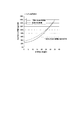
また、図4および図5は、1日当たりの電力量比率と日平均外気温との関係を、冷凍条件が−40℃の場合と、冷蔵条件が−10℃の場合とについて示したものである。この結果によれば、いずれの場合も、従来の冷凍機11より本発明の冷凍機11の方が電力量比率が低くなっていることを示している。さらに、本発明の過冷却熱交換器14により過冷却を行った場合には、外気温が16℃以上のいずれの温度になった場合でも、電力量比率が60%程度を維持することを示しており、本発明の冷凍機11の電力量が低下し、効率が高くなっていることがわかる。
FIG. 4 and FIG. 5 show the relationship between the ratio of the electric energy per day and the daily average outside air temperature when the refrigeration condition is −40 ° C. and when the refrigeration condition is −10 ° C. . According to this result, in any case, it is shown that the electric energy ratio of the
なお、本発明は前記実施形態に限定されるものではなく、本発明の趣旨に基づいて種々の変形が可能である。 In addition, this invention is not limited to the said embodiment, A various deformation | transformation is possible based on the meaning of this invention.
2 ショーケース
10 冷凍サイクル回路
11 冷凍機
12 冷凍用圧縮機
13 ガスクーラ
14 過冷却熱交換器
15 冷凍用蒸発器
16 冷凍用冷媒配管
17 送風ファン
18 仕切り板
30 空調回路
31 空気調和装置
32 冷温水機
33 空調用往き配管
34 空調用戻り配管
35 空調用ポンプ
36 冷水用往き配管
37 冷水用戻り配管
38 空調用開閉弁
39 冷水用開閉弁
40 暖房用熱交換器
41 暖房用往き配管
42 暖房用戻り配管
43 暖房用開閉弁
50 排熱源
51 排熱源用配管
52 排熱源用ポンプ
53 排熱源供給配管
54 排熱源戻り配管
55 冷温水機用三方弁
56 暖房用熱交換器用三方弁
60 第1コントローラ
64 第2コントローラ
70 高温再生器
71 低温再生器
72 排熱再生器
73 凝縮器
74 蒸発器
75 吸収器
DESCRIPTION OF
Claims (9)
前記冷凍サイクル回路は、前記冷温水機の冷水を利用して前記ガスクーラから出た冷媒の過冷却を行う過冷却熱交換器を備えていることを特徴とする冷凍システム。 A refrigeration cycle circuit that constitutes a refrigerator using a carbon dioxide refrigerant with an air-cooled gas cooler, and an air-conditioning circuit that performs air-conditioning with the cold water of the cold / hot water machine,
The said refrigeration cycle circuit is provided with the supercooling heat exchanger which supercools the refrigerant | coolant which came out of the said gas cooler using the cold water of the said cold / hot water machine.
Priority Applications (1)
| Application Number | Priority Date | Filing Date | Title |
|---|---|---|---|
| JP2014136394A JP6347427B2 (en) | 2014-07-02 | 2014-07-02 | Refrigeration system |
Applications Claiming Priority (1)
| Application Number | Priority Date | Filing Date | Title |
|---|---|---|---|
| JP2014136394A JP6347427B2 (en) | 2014-07-02 | 2014-07-02 | Refrigeration system |
Publications (2)
| Publication Number | Publication Date |
|---|---|
| JP2016014496A true JP2016014496A (en) | 2016-01-28 |
| JP6347427B2 JP6347427B2 (en) | 2018-06-27 |
Family
ID=55230818
Family Applications (1)
| Application Number | Title | Priority Date | Filing Date |
|---|---|---|---|
| JP2014136394A Active JP6347427B2 (en) | 2014-07-02 | 2014-07-02 | Refrigeration system |
Country Status (1)
| Country | Link |
|---|---|
| JP (1) | JP6347427B2 (en) |
Citations (13)
| Publication number | Priority date | Publication date | Assignee | Title |
|---|---|---|---|---|
| JP2004170001A (en) * | 2002-11-20 | 2004-06-17 | Sanyo Electric Co Ltd | Refrigerating system |
| JP2006308147A (en) * | 2005-04-26 | 2006-11-09 | Yukinobu Ikemoto | Heat pump system |
| JP2008051370A (en) * | 2006-08-23 | 2008-03-06 | Matsushita Electric Ind Co Ltd | Water cooling type refrigerating system and cold storage equipped with the same |
| JP2008281218A (en) * | 2007-05-08 | 2008-11-20 | Ntt Facilities Inc | Air conditioning system and control method for it |
| JP2009014271A (en) * | 2007-07-04 | 2009-01-22 | Mitsubishi Electric Corp | Refrigerating cycle apparatus |
| JP2009036506A (en) * | 2007-07-09 | 2009-02-19 | Ntt Facilities Inc | Air-conditioning system and its operating method |
| JP2010276230A (en) * | 2009-05-27 | 2010-12-09 | Sanyo Electric Co Ltd | Refrigerating device |
| JP2012167833A (en) * | 2011-02-10 | 2012-09-06 | Ntt Facilities Inc | Secondary refrigerant air conditioning system and operation method of the same |
| JP2013011423A (en) * | 2011-06-30 | 2013-01-17 | Sanyo Electric Co Ltd | Refrigerating apparatus |
| JP2013174402A (en) * | 2012-02-27 | 2013-09-05 | Panasonic Corp | Refrigerating device |
| JP2013245857A (en) * | 2012-05-24 | 2013-12-09 | Panasonic Corp | Refrigeration device |
| JP2015178921A (en) * | 2014-03-19 | 2015-10-08 | サンデンホールディングス株式会社 | Refrigeration device |
| JP2015218930A (en) * | 2014-05-15 | 2015-12-07 | パナソニックIpマネジメント株式会社 | Refrigeration system |
-
2014
- 2014-07-02 JP JP2014136394A patent/JP6347427B2/en active Active
Patent Citations (13)
| Publication number | Priority date | Publication date | Assignee | Title |
|---|---|---|---|---|
| JP2004170001A (en) * | 2002-11-20 | 2004-06-17 | Sanyo Electric Co Ltd | Refrigerating system |
| JP2006308147A (en) * | 2005-04-26 | 2006-11-09 | Yukinobu Ikemoto | Heat pump system |
| JP2008051370A (en) * | 2006-08-23 | 2008-03-06 | Matsushita Electric Ind Co Ltd | Water cooling type refrigerating system and cold storage equipped with the same |
| JP2008281218A (en) * | 2007-05-08 | 2008-11-20 | Ntt Facilities Inc | Air conditioning system and control method for it |
| JP2009014271A (en) * | 2007-07-04 | 2009-01-22 | Mitsubishi Electric Corp | Refrigerating cycle apparatus |
| JP2009036506A (en) * | 2007-07-09 | 2009-02-19 | Ntt Facilities Inc | Air-conditioning system and its operating method |
| JP2010276230A (en) * | 2009-05-27 | 2010-12-09 | Sanyo Electric Co Ltd | Refrigerating device |
| JP2012167833A (en) * | 2011-02-10 | 2012-09-06 | Ntt Facilities Inc | Secondary refrigerant air conditioning system and operation method of the same |
| JP2013011423A (en) * | 2011-06-30 | 2013-01-17 | Sanyo Electric Co Ltd | Refrigerating apparatus |
| JP2013174402A (en) * | 2012-02-27 | 2013-09-05 | Panasonic Corp | Refrigerating device |
| JP2013245857A (en) * | 2012-05-24 | 2013-12-09 | Panasonic Corp | Refrigeration device |
| JP2015178921A (en) * | 2014-03-19 | 2015-10-08 | サンデンホールディングス株式会社 | Refrigeration device |
| JP2015218930A (en) * | 2014-05-15 | 2015-12-07 | パナソニックIpマネジメント株式会社 | Refrigeration system |
Also Published As
| Publication number | Publication date |
|---|---|
| JP6347427B2 (en) | 2018-06-27 |
Similar Documents
| Publication | Publication Date | Title |
|---|---|---|
| CN101487639B (en) | Air-cooling double-evaporator heat pump unit | |
| JP2004003801A (en) | Refrigeration equipment using carbon dioxide as refrigerant | |
| JP2006023006A (en) | Refrigeration facility | |
| KR101196505B1 (en) | Heat pump using two stage compressors | |
| JP2015218944A (en) | Refrigeration system | |
| KR20100027353A (en) | Refrigerating and freezing apparatus | |
| JP4670576B2 (en) | vending machine | |
| KR20130077108A (en) | Heat pump type cool and hot water supply device | |
| CN102305496B (en) | Air-cooled heat pump unit | |
| JP6347427B2 (en) | Refrigeration system | |
| KR101352516B1 (en) | Warm water supplying and refrigerating system and method controlling the same | |
| JP2008102941A (en) | Vending machine | |
| KR101043034B1 (en) | The ice-cycle system of waste heat recovery system | |
| KR102095882B1 (en) | heating and cooling system of building using an electric apparatus | |
| JP6455752B2 (en) | Refrigeration system | |
| KR20030082822A (en) | The Combined Cooling and Heating Ice Regenerative System | |
| JP6613404B2 (en) | Refrigeration system | |
| CN206073329U (en) | A kind of refrigeration air-cooled unit | |
| JP6344686B2 (en) | Refrigeration system | |
| KR200428357Y1 (en) | Cold water/hot water producing system for heat pump | |
| WO2013046723A1 (en) | Hot-water-supplying, air-conditioning system | |
| JP4429960B2 (en) | Vending machine with cooling and heating system | |
| KR101403452B1 (en) | Chiller System | |
| JP2003004330A (en) | Exhaust heat recovery air conditioner | |
| JP4100462B2 (en) | Heat utilization system |
Legal Events
| Date | Code | Title | Description |
|---|---|---|---|
| A621 | Written request for application examination |
Free format text: JAPANESE INTERMEDIATE CODE: A621 Effective date: 20170222 |
|
| A977 | Report on retrieval |
Free format text: JAPANESE INTERMEDIATE CODE: A971007 Effective date: 20171214 |
|
| A131 | Notification of reasons for refusal |
Free format text: JAPANESE INTERMEDIATE CODE: A131 Effective date: 20171226 |
|
| A521 | Request for written amendment filed |
Free format text: JAPANESE INTERMEDIATE CODE: A523 Effective date: 20180222 |
|
| TRDD | Decision of grant or rejection written | ||
| A01 | Written decision to grant a patent or to grant a registration (utility model) |
Free format text: JAPANESE INTERMEDIATE CODE: A01 Effective date: 20180424 |
|
| A61 | First payment of annual fees (during grant procedure) |
Free format text: JAPANESE INTERMEDIATE CODE: A61 Effective date: 20180521 |
|
| R151 | Written notification of patent or utility model registration |
Ref document number: 6347427 Country of ref document: JP Free format text: JAPANESE INTERMEDIATE CODE: R151 |