JP2016007345A - Game system - Google Patents

Game system Download PDF

Info

Publication number
JP2016007345A
JP2016007345A JP2014129599A JP2014129599A JP2016007345A JP 2016007345 A JP2016007345 A JP 2016007345A JP 2014129599 A JP2014129599 A JP 2014129599A JP 2014129599 A JP2014129599 A JP 2014129599A JP 2016007345 A JP2016007345 A JP 2016007345A
Authority
JP
Japan
Prior art keywords
load
actuator
unit
load information
game
Prior art date
Legal status (The legal status is an assumption and is not a legal conclusion. Google has not performed a legal analysis and makes no representation as to the accuracy of the status listed.)
Pending
Application number
JP2014129599A
Other languages
Japanese (ja)
Other versions
JP2016007345A5 (en
Inventor
信之 鷹啄
Nobuyuki Takakuchi
信之 鷹啄
和将 伊藤
Kazumasa Ito
和将 伊藤
Current Assignee (The listed assignees may be inaccurate. Google has not performed a legal analysis and makes no representation or warranty as to the accuracy of the list.)
Sony Interactive Entertainment Inc
Original Assignee
Sony Computer Entertainment Inc
Priority date (The priority date is an assumption and is not a legal conclusion. Google has not performed a legal analysis and makes no representation as to the accuracy of the date listed.)
Filing date
Publication date
Application filed by Sony Computer Entertainment Inc filed Critical Sony Computer Entertainment Inc
Priority to JP2014129599A priority Critical patent/JP2016007345A/en
Priority to PCT/JP2015/055414 priority patent/WO2015198634A1/en
Publication of JP2016007345A publication Critical patent/JP2016007345A/en
Publication of JP2016007345A5 publication Critical patent/JP2016007345A5/ja
Pending legal-status Critical Current

Links

Images

Classifications

    • AHUMAN NECESSITIES
    • A63SPORTS; GAMES; AMUSEMENTS
    • A63FCARD, BOARD, OR ROULETTE GAMES; INDOOR GAMES USING SMALL MOVING PLAYING BODIES; VIDEO GAMES; GAMES NOT OTHERWISE PROVIDED FOR
    • A63F13/00Video games, i.e. games using an electronically generated display having two or more dimensions
    • A63F13/20Input arrangements for video game devices
    • A63F13/24Constructional details thereof, e.g. game controllers with detachable joystick handles
    • AHUMAN NECESSITIES
    • A63SPORTS; GAMES; AMUSEMENTS
    • A63FCARD, BOARD, OR ROULETTE GAMES; INDOOR GAMES USING SMALL MOVING PLAYING BODIES; VIDEO GAMES; GAMES NOT OTHERWISE PROVIDED FOR
    • A63F13/00Video games, i.e. games using an electronically generated display having two or more dimensions
    • A63F13/25Output arrangements for video game devices
    • A63F13/28Output arrangements for video game devices responding to control signals received from the game device for affecting ambient conditions, e.g. for vibrating players' seats, activating scent dispensers or affecting temperature or light
    • A63F13/285Generating tactile feedback signals via the game input device, e.g. force feedback
    • AHUMAN NECESSITIES
    • A63SPORTS; GAMES; AMUSEMENTS
    • A63FCARD, BOARD, OR ROULETTE GAMES; INDOOR GAMES USING SMALL MOVING PLAYING BODIES; VIDEO GAMES; GAMES NOT OTHERWISE PROVIDED FOR
    • A63F13/00Video games, i.e. games using an electronically generated display having two or more dimensions
    • A63F13/50Controlling the output signals based on the game progress
    • GPHYSICS
    • G06COMPUTING; CALCULATING OR COUNTING
    • G06FELECTRIC DIGITAL DATA PROCESSING
    • G06F3/00Input arrangements for transferring data to be processed into a form capable of being handled by the computer; Output arrangements for transferring data from processing unit to output unit, e.g. interface arrangements
    • G06F3/01Input arrangements or combined input and output arrangements for interaction between user and computer

Abstract

PROBLEM TO BE SOLVED: To provide a technique in which a load is effectively imparted to an operation section.SOLUTION: A load information acquisition section 206 acquires load information corresponding to an object which is selected by a user, from a game application. A drive control section 208, according to the acquired load information, drives a first actuator 94a and a second actuator 94b, and imparts a load to an analog stick including an operation shaft 157. The load is imparted in a direction along an inclination direction of the analog stick, and the direction may be a direction reverse to the inclination direction and may be the same direction.

Description

本発明は、アナログスティックなどの操作部に負荷を付与する技術に関する。   The present invention relates to a technique for applying a load to an operation unit such as an analog stick.

ゲームシステムは、ユーザ操作を入力するための操作部と、入力されたユーザ操作をゲーム進行に反映して出力する処理部を備えて構成される。特許文献1は、ゲームコントローラ把持部の筐体内部に振動子を固定しておき、ゲームアプリケーションの進行状況に応じて振動子を駆動するゲームシステムを開示する。また特許文献2は、操作レバーを傾動させて移動体の操作を行う際に、移動体の動作状況に応じて操作レバーから操作者へ反力が作用するようにした操作レバー装置を開示する。   The game system is configured to include an operation unit for inputting a user operation and a processing unit for reflecting the input user operation in the game progress and outputting it. Patent Document 1 discloses a game system in which a vibrator is fixed inside a housing of a game controller holding unit and the vibrator is driven according to the progress of a game application. Patent Document 2 discloses an operation lever device in which a reaction force is applied from the operation lever to the operator according to the operation state of the moving body when the operation body is operated by tilting the operation lever.

米国特許第8403752号明細書US Pat. No. 8,403,752 特開平6−83469号公報JP-A-6-83469

ゲームシステムにおいて、操作部は、ユーザが直接触って物理的に動かす手段であり、アナログスティックや操作ボタンなどを有して構成される。本発明者は、操作部に負荷を付与することで、新たな面白さをユーザに提供できるゲームシステムの可能性に着目し、操作部に付与する負荷を効果的に制御する技術を想到するに至った。   In the game system, the operation unit is a means for a user to directly touch and physically move, and includes an analog stick, an operation button, and the like. The present inventor pays attention to the possibility of a game system that can provide a user with new fun by applying a load to the operation unit, and arrives at a technique for effectively controlling the load applied to the operation unit. It came.

そこで本発明は、操作部に負荷を効果的に付与する技術を提供することを目的とする。   Then, an object of this invention is to provide the technique which provides a load to an operation part effectively.

上記課題を解決するために、本発明のある態様のゲームシステムは、ゲームシステムであって、ユーザが操作する操作部と、操作部に負荷を付与するアクチュエータと、アクチュエータを制御する制御部と、ゲームアプリケーションから、ユーザにより選択されたオブジェクトに対応する負荷情報を取得する取得部とを備える。制御部は、取得部が取得した負荷情報にしたがってアクチュエータを制御する。オブジェクトに対応する負荷情報は、アクチュエータにより生成する負荷を特定できる情報であればよい。   In order to solve the above problems, a game system according to an aspect of the present invention is a game system, an operation unit operated by a user, an actuator that applies a load to the operation unit, a control unit that controls the actuator, And an acquisition unit that acquires load information corresponding to the object selected by the user from the game application. The control unit controls the actuator according to the load information acquired by the acquisition unit. The load information corresponding to the object may be information that can identify the load generated by the actuator.

本発明の別の態様もまた、ゲームシステムである。このゲームシステムは、ユーザが操作する操作部と、操作部に負荷を付与するアクチュエータと、アクチュエータを制御する制御部と、負荷情報を保持する保持部と、保持部から負荷情報を取得する取得部と、操作部の操作を受け付ける受付部とを備える。制御部は、取得部が取得した負荷情報にしたがってアクチュエータを制御して、受付部が受け付けた操作部の操作に対して負荷を付与させる。   Another aspect of the present invention is also a game system. The game system includes an operation unit operated by a user, an actuator that applies a load to the operation unit, a control unit that controls the actuator, a holding unit that holds load information, and an acquisition unit that acquires load information from the holding unit And a reception unit that receives an operation of the operation unit. The control unit controls the actuator according to the load information acquired by the acquisition unit, and applies a load to the operation of the operation unit received by the reception unit.

なお、以上の構成要素の任意の組み合わせ、本発明の表現を方法、装置、システム、記録媒体、コンピュータプログラムなどの間で変換したものもまた、本発明の態様として有効である。   It should be noted that any combination of the above-described constituent elements and a conversion of the expression of the present invention between a method, an apparatus, a system, a recording medium, a computer program, and the like are also effective as an aspect of the present invention.

本発明によると、操作部に負荷を効果的に付与する技術を提供できる。   According to the present invention, it is possible to provide a technique for effectively applying a load to the operation unit.

(a)はゲーム装置の前面を示す図であり、(b)はゲーム装置の背面を示す図である。(A) is a figure which shows the front surface of a game device, (b) is a figure which shows the back surface of a game device. (a)はゲーム装置の上面を示す図であり、(b)はゲーム装置の下面を示す図であり、(c)はゲーム装置の左側面を示す図である。(A) is a figure which shows the upper surface of a game device, (b) is a figure which shows the lower surface of a game device, (c) is a figure which shows the left side surface of a game device. ゲームシステムの機能ブロックを示す図である。It is a figure which shows the functional block of a game system. アナログスティックの傾動を実現する多方向操作入力装置を説明するための分解斜視図である。It is a disassembled perspective view for demonstrating the multidirectional operation input device which implement | achieves tilting of an analog stick. (a)および(b)は、多方向操作入力装置の断面を示す図である。(A) And (b) is a figure which shows the cross section of a multidirectional operation input device. 操作部に負荷を付与するためのゲームシステムの構成を示す図である。It is a figure which shows the structure of the game system for providing a load to an operation part. 表示装置に表示されるキャラクタ選択画面を示す図である。It is a figure which shows the character selection screen displayed on a display apparatus. (a)はキャラクタと負荷レベルの対応表を示す図であり、(b)は装備品と負荷レベルの対応表を示す図である。(A) is a figure which shows the correspondence table of a character and a load level, (b) is a figure which shows the correspondence table of an equipment and a load level. キャラクタと負荷レベルの対応表の別の例を示す図である。It is a figure which shows another example of the conversion table of a character and a load level. (a)はアナログスティックの傾動量とばね力の関係を示す図であり、(b)(c)は、アクチュエータ生成力と反発力の関係を示す図である。(A) is a figure which shows the relationship between the tilting amount of an analog stick, and a spring force, (b) (c) is a figure which shows the relationship between an actuator production | generation force and a repulsive force. アクチュエータ生成力とアシスト力の関係を示す図である。It is a figure which shows the relationship between an actuator production | generation force and assist force. ゲームシステムの構成の別の例を示す図である。It is a figure which shows another example of a structure of a game system. 4アクチュエータ構造を示す図である。It is a figure which shows 4 actuator structure. (a)(b)はアナログスティックの操作方向と、外力の方向の関係を示す図である。(A) (b) is a figure which shows the relationship between the operation direction of an analog stick, and the direction of external force. 表示装置に表示される負荷設定画面を示す図である。It is a figure which shows the load setting screen displayed on a display apparatus.

本実施例のゲームシステムは、ユーザが操作する操作部と、入力されたユーザ操作をゲーム進行に反映して出力する処理部を有する。ゲームシステムは、操作部と処理部とが一体として構成されてもよく、また操作部と処理部とが別体として構成されてもよい。以下の実施例においては、操作部と処理部とが一体として構成されるゲームシステムについて説明するが、ゲームシステムは、操作部がゲームコントローラ、ジョイスティックなどのユーザインタフェースであり、処理部が据置型のゲーム機であって、操作部と処理部とが無線または有線で接続されたものであってもよい。以下、ゲームシステムが、携帯型のゲーム機として構成される場合について説明する。   The game system according to the present embodiment includes an operation unit operated by a user and a processing unit that outputs an input user operation reflected on the progress of the game. In the game system, the operation unit and the processing unit may be configured integrally, or the operation unit and the processing unit may be configured separately. In the following embodiments, a game system in which an operation unit and a processing unit are integrated will be described. However, the game system has a user interface such as a game controller or a joystick, and the processing unit is a stationary type. It is a game machine, Comprising: The operation part and the process part may be connected by radio | wireless or a wire communication. Hereinafter, a case where the game system is configured as a portable game machine will be described.

[前面部の構成]
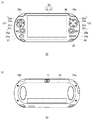
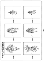
図1(a)は、ゲーム装置10の前面を示す。ゲーム装置10は、ユーザが操作する操作部と、ゲームアプリケーションを処理する処理部とを一体にしたゲームシステムであり、本実施例において「ゲームシステム」および「ゲーム装置」は同義である。
[Configuration of the front part]
FIG. 1A shows the front surface of the game apparatus 10. The game apparatus 10 is a game system in which an operation unit operated by a user and a processing unit that processes a game application are integrated. In this embodiment, “game system” and “game apparatus” are synonymous.

ゲーム装置10は、横長の筐体により形成され、ユーザが把持する左右の領域は、円弧状の外郭を有している。ゲーム装置10の前面には、矩形のタッチパネル50が設けられる。タッチパネル50は、表示装置20と、表示装置20の表面を覆う透明な前面タッチパッド21から構成される。表示装置20は有機EL(Electro-Liminescence)パネルであり、画像を表示する。なお表示装置20は液晶パネルなどの表示手段であってもよい。前面タッチパッド21は、同時にタッチされた複数ポイントの検出機能をもつマルチタッチパッドであって、タッチパネル50はマルチタッチスクリーンとして構成される。   The game apparatus 10 is formed by a horizontally long case, and the left and right areas gripped by the user have an arcuate outline. A rectangular touch panel 50 is provided on the front surface of the game apparatus 10. The touch panel 50 includes a display device 20 and a transparent front touch pad 21 that covers the surface of the display device 20. The display device 20 is an organic EL (Electro-Liminescence) panel and displays an image. The display device 20 may be a display unit such as a liquid crystal panel. The front touch pad 21 is a multi-touch pad having a function of detecting a plurality of points touched at the same time, and the touch panel 50 is configured as a multi-touch screen.

タッチパネル50の右側には、菱形の頂点にそれぞれ位置する△ボタン22a、○ボタン22b、×ボタン22c、□ボタン22d(以下、総称する場合には「操作ボタン22」とよぶ)が設けられ、タッチパネル50の左側には、上キー23a、左キー23b、下キー23c、右キー23d(以下、総称する場合には「方向キー23」とよぶ)が設けられる。ユーザは方向キー23を操作して、上下左右および斜方の8方向を入力できる。方向キー23の下側には左スティック24aが設けられ、また操作ボタン22の下側には右スティック24bが設けられる。ユーザは左スティック24aまたは右スティック24b(以下、総称する場合には「アナログスティック24」とよぶ)を傾動して、方向および傾動量を入力する。なおアナログスティック24は、中心の基準位置からの方向を入力できるスライド式のパッドとして構成されてもよい。筐体の左右頂部には、Lボタン26a、Rボタン26bが設けられる。操作ボタン22、方向キー23、アナログスティック24、Lボタン26a、Rボタン26bは、ユーザが操作する操作部を構成する。   On the right side of the touch panel 50, a triangle button 22a, a circle button 22b, a x button 22c, and a square button 22d (hereinafter collectively referred to as “operation buttons 22”) are provided on the right side of the rhombus. On the left side of 50, an upper key 23a, a left key 23b, a lower key 23c, and a right key 23d (hereinafter, collectively referred to as “direction key 23”) are provided. The user can input the eight directions of up / down / left / right and diagonal by operating the direction key 23. A left stick 24 a is provided below the direction key 23, and a right stick 24 b is provided below the operation button 22. The user tilts the left stick 24a or the right stick 24b (hereinafter, collectively referred to as “analog stick 24”), and inputs a direction and a tilt amount. The analog stick 24 may be configured as a sliding pad that can input a direction from the center reference position. An L button 26a and an R button 26b are provided on the left and right tops of the housing. The operation button 22, the direction key 23, the analog stick 24, the L button 26a, and the R button 26b constitute an operation unit operated by the user.

操作ボタン22の近傍に、前面カメラ30が設けられる。左スティック24aの左側および右スティック24bの右側には、それぞれ音声を出力する左スピーカ25aおよび右スピーカ25b(以下、総称する場合には「スピーカ25」とよぶ)が設けられる。また左スティック24aの下側にHOMEボタン27が設けられ、右スティック24bの下側にSTARTボタン28およびSELECTボタン29が設けられる。   A front camera 30 is provided in the vicinity of the operation button 22. On the left side of the left stick 24a and the right side of the right stick 24b, a left speaker 25a and a right speaker 25b (hereinafter, collectively referred to as “speaker 25”) that output sound are provided, respectively. A HOME button 27 is provided below the left stick 24a, and a START button 28 and a SELECT button 29 are provided below the right stick 24b.

[背面部の構成]
図1(b)は、ゲーム装置10の背面を示す。ゲーム装置10の背面には、背面カメラ31および背面タッチパッド32が設けられる。背面タッチパッド32は、前面タッチパッド21と同様に、マルチタッチパッドとして構成される。ゲーム装置10は、前面および背面において、2つのカメラおよびタッチパッドを搭載している。
[Configuration of back side]
FIG. 1B shows the back of the game apparatus 10. A rear camera 31 and a rear touch pad 32 are provided on the back of the game apparatus 10. The rear touch pad 32 is configured as a multi-touch pad, like the front touch pad 21. The game apparatus 10 is equipped with two cameras and a touchpad on the front surface and the back surface.

[上面部の構成]
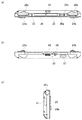
図2(a)は、ゲーム装置10の上面を示す。既述したように、ゲーム装置10の上面の左右端側に、Lボタン26a、Rボタン26bがそれぞれ設けられる。Lボタン26aの右側には電源ボタン33が設けられ、ユーザは、電源ボタン33を所定時間(たとえば2秒)以上押下することで、電源をオンまたはオフする。
[Configuration of top surface]
FIG. 2A shows the upper surface of the game apparatus 10. As described above, the L button 26a and the R button 26b are provided on the left and right ends of the upper surface of the game apparatus 10, respectively. A power button 33 is provided on the right side of the L button 26a, and the user turns the power on or off by pressing the power button 33 for a predetermined time (for example, 2 seconds) or longer.

ゲームカードスロット34は、ゲームプログラムが記録されたゲームカードを差し込むための差込口であり、この図では、ゲームカードスロット34がスロットカバーにより覆われている状態が示される。なおゲームカードスロット34の近傍に、ゲームカードがアクセスされているときに点滅するLEDランプが設けられてもよい。アクセサリ端子35は、周辺機器(アクセサリ)を接続するための端子であり、この図ではアクセサリ端子35が端子カバーにより覆われている状態が示される。アクセサリ端子35とRボタン26bの間には、ボリュームを調整するための−ボタン36aと+ボタン36bが設けられている。   The game card slot 34 is an insertion slot for inserting a game card in which a game program is recorded. In this figure, the game card slot 34 is covered with a slot cover. An LED lamp that blinks when the game card is being accessed may be provided in the vicinity of the game card slot 34. The accessory terminal 35 is a terminal for connecting a peripheral device (accessory), and this figure shows a state where the accessory terminal 35 is covered with a terminal cover. Between the accessory terminal 35 and the R button 26b, a-button 36a and a + button 36b for adjusting the volume are provided.

[下面部の構成]
図2(b)は、ゲーム装置10の下面を示す。メモリカードスロット37は、メモリカードを差し込むための差込口であり、この図では、メモリカードスロット37が、スロットカバーにより覆われている状態が示される。ゲーム装置10の下面において、音声入出力端子38、マイク39およびマルチユース端子40が設けられる。マルチユース端子40はUSB(Universal Serial Bus)に対応し、USBケーブルを介して他の機器と接続できる。
[Configuration of bottom surface]
FIG. 2B shows the lower surface of the game apparatus 10. The memory card slot 37 is an insertion slot for inserting a memory card, and this figure shows a state in which the memory card slot 37 is covered with a slot cover. On the lower surface of the game apparatus 10, a voice input / output terminal 38, a microphone 39, and a multi-use terminal 40 are provided. The multi-use terminal 40 corresponds to USB (Universal Serial Bus) and can be connected to other devices via a USB cable.

[左側面部の構成]
図2(c)は、ゲーム装置10の左側面を示す。ゲーム装置10の左側面には、SIMカードの差込口であるSIMカードスロット41が設けられる。
[Configuration of left side]
FIG. 2C shows the left side surface of the game apparatus 10. On the left side of the game apparatus 10, a SIM card slot 41, which is a SIM card insertion slot, is provided.

[ゲーム装置の内部構成]
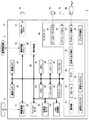
図3は、ゲームシステム1の機能ブロックを示す。ゲーム装置10における各構成はバス92によって互いに接続されている。無線通信モジュール71はIEEE802.11b/g等の通信規格に準拠した無線LANモジュールによって構成され、AP2を介して、外部ネットワークに接続する。なお無線通信モジュール71は、ブルートゥース(登録商標)プロトコルの通信機能を有してもよい。携帯電話モジュール72は、ITU(International Telecommunication Union;国際電気通信連合)によって定められたIMT−2000(International Mobile Telecommunication 2000)規格に準拠した第3世代(3rd Generation)デジタル携帯電話方式に対応し、携帯電話網4に接続する。SIMカードスロット41には、携帯電話の電話番号を特定するための固有のID番号が記録されたSIMカード74が挿入される。SIMカード74がSIMカードスロット41に挿入されることで、携帯電話モジュール72は、携帯電話網4との間で通信可能となる。
[Internal configuration of game device]
FIG. 3 shows functional blocks of the game system 1. Each component in the game apparatus 10 is connected to each other by a bus 92. The wireless communication module 71 is configured by a wireless LAN module compliant with a communication standard such as IEEE802.11b / g, and is connected to an external network via the AP2. The wireless communication module 71 may have a Bluetooth (registered trademark) protocol communication function. The mobile phone module 72 corresponds to the 3rd generation digital mobile phone system conforming to the IMT-2000 (International Mobile Telecommunication 2000) standard defined by ITU (International Telecommunication Union), and is portable. Connect to the telephone network 4. Into the SIM card slot 41, a SIM card 74 in which a unique ID number for specifying the telephone number of the mobile phone is recorded is inserted. By inserting the SIM card 74 into the SIM card slot 41, the mobile phone module 72 can communicate with the mobile phone network 4.

CPU(Central Processing Unit)60は、メインメモリ64にロードされたプログラムなどを実行する。GPU(Graphics Processing Unit)62は、画像処理に必要な計算を実行する。メインメモリ64は、RAM(Random Access Memory)などにより構成され、CPU60が使用するプログラムやデータなどを記憶する。ストレージ66は、NAND型フラッシュメモリ(NAND-type flash memory)などにより構成され、内蔵型の補助記憶装置として利用される。   A CPU (Central Processing Unit) 60 executes a program loaded in the main memory 64. A GPU (Graphics Processing Unit) 62 performs calculations necessary for image processing. The main memory 64 is configured by a RAM (Random Access Memory) or the like, and stores programs and data used by the CPU 60. The storage 66 is configured by a NAND-type flash memory or the like, and is used as a built-in auxiliary storage device.

モーションセンサ67は、ゲーム装置10の動きを検出し、地磁気センサ68は、3軸方向の地磁気を検出する。GPS制御部69は、GPS衛星からの信号を受信し、現在位置を算出する。前面カメラ30および背面カメラ31は、画像を撮像し、画像データを入力する。前面カメラ30および背面カメラ31は、CMOSイメージセンサ(Complementary Metal Oxide Semiconductor Image Sensor)によって構成される。   The motion sensor 67 detects the movement of the game apparatus 10, and the geomagnetic sensor 68 detects triaxial geomagnetism. The GPS control unit 69 receives a signal from a GPS satellite and calculates a current position. The front camera 30 and the rear camera 31 capture an image and input image data. The front camera 30 and the rear camera 31 are constituted by CMOS image sensors (Complementary Metal Oxide Semiconductor Image Sensors).

表示装置20は、有機EL表示装置であり、陰極および陽極に電圧を印加することで発光する発光素子を有する。省電力モードでは、電極間に印加する電圧を通常よりも低くすることで、表示装置20を減光状態とすることができ、電力消費を抑えられる。なお表示装置20はバックライトを備えた液晶パネル表示装置であってもよい。省電力モードでは、バックライトの光量を下げることで、液晶パネル表示装置を減光状態として、電力消費を抑えることができる。   The display device 20 is an organic EL display device and includes a light emitting element that emits light by applying a voltage to a cathode and an anode. In the power saving mode, the voltage applied between the electrodes is made lower than usual, so that the display device 20 can be dimmed and power consumption can be suppressed. The display device 20 may be a liquid crystal panel display device provided with a backlight. In the power saving mode, by reducing the amount of light from the backlight, the liquid crystal panel display device can be in a dimmed state and power consumption can be suppressed.

インタフェース90において、操作部70は、ゲーム装置10における各種操作手段を含み、具体的には、操作ボタン22、方向キー23、アナログスティック24、Lボタン26a、Rボタン26b、HOMEボタン27、STARTボタン28、SELECTボタン29、電源ボタン33、−ボタン36a、+ボタン36bを含む。前面タッチパッド21および背面タッチパッド32は、マルチタッチパッドであり、前面タッチパッド21は、表示装置20の表面に重ね合わせて配置される。スピーカ25は、ゲーム装置10の各機能により生成される音声を出力し、マイク39は、ゲーム装置10の周辺の音声を入力する。音声入出力端子38は、外部のマイクからステレオ音声を入力し、外部のヘッドホンなどへステレオ音声を出力する。   In the interface 90, the operation unit 70 includes various operation means in the game apparatus 10. Specifically, the operation button 22, the direction key 23, the analog stick 24, the L button 26a, the R button 26b, the HOME button 27, and the START button. 28, a SELECT button 29, a power button 33, a-button 36a, and a + button 36b. The front touchpad 21 and the rear touchpad 32 are multi-touchpads, and the front touchpad 21 is disposed on the surface of the display device 20. The speaker 25 outputs sound generated by each function of the game apparatus 10, and the microphone 39 inputs sound around the game apparatus 10. The audio input / output terminal 38 inputs stereo sound from an external microphone and outputs stereo sound to external headphones or the like.

ゲームカードスロット34には、ゲームプログラムを記録したゲームカード76が差し込まれる。ゲームカード76は、データの書込可能な記録領域を有しており、ゲームカードスロット34に装着されると、メディアドライブにより、データの書込/読出が行われる。メモリカードスロット37には、メモリカード78が差し込まれる。メモリカード78は、メモリカードスロット37に装着されると、外付け型の補助記憶装置として利用される。マルチユース端子40は、USB端子として利用でき、USBケーブル80を接続されて、他のUSB機器とデータの送受信を行う。アクセサリ端子35には、周辺機器が接続される。   A game card 76 in which a game program is recorded is inserted into the game card slot 34. The game card 76 has a recording area in which data can be written. When the game card 76 is inserted into the game card slot 34, data is written / read by the media drive. A memory card 78 is inserted into the memory card slot 37. When the memory card 78 is inserted into the memory card slot 37, it is used as an external auxiliary storage device. The multi-use terminal 40 can be used as a USB terminal, and is connected to a USB cable 80 to transmit / receive data to / from another USB device. A peripheral device is connected to the accessory terminal 35.

本実施例のゲームシステム1は、ユーザが操作する操作部70に負荷を付与するアクチュエータ94を備える。アクチュエータ94は、たとえばモータなどの駆動子を有して構成され、CPU60により制御されるドライバIC96から供給される制御信号をもとに、ユーザによる操作部70の操作に対して作用させる負荷(荷重)を生成する。アクチュエータ94は操作部70に機械的に連結されて、操作部70に付与する負荷を生成してもよいが、たとえば電磁石により操作部70に電磁的に結合されて、操作部70に付与する負荷を生成してもよい。なおアクチュエータ94は、たとえばゲーム状況に応じて、ユーザによる操作部70の操作に関係なく、操作部70に対して作用させる負荷を生成してもよい。   The game system 1 according to the present embodiment includes an actuator 94 that applies a load to the operation unit 70 operated by the user. The actuator 94 is configured to have a driver such as a motor, for example, and based on a control signal supplied from a driver IC 96 controlled by the CPU 60, a load (load) that acts on the operation of the operation unit 70 by the user. ) Is generated. The actuator 94 may be mechanically coupled to the operation unit 70 to generate a load to be applied to the operation unit 70. However, for example, a load to be applied to the operation unit 70 by being electromagnetically coupled to the operation unit 70 by an electromagnet, for example. May be generated. The actuator 94 may generate a load that acts on the operation unit 70 regardless of the operation of the operation unit 70 by the user, for example, depending on the game situation.

以下、操作部70の一例として、多方向操作入力装置に連結したアナログスティック24にアクチュエータ94が負荷を付与する場合を説明するが、操作ボタン22や方向キー23などの他の操作手段にアクチュエータ94が負荷を付与してもよい。押しボタン式の操作手段にアクチュエータ94を取り付ける際には、アクチュエータ94が操作手段の押下方向に沿った負荷(外力)を付与可能に設けられることが好ましい。   Hereinafter, a case where the actuator 94 applies a load to the analog stick 24 connected to the multidirectional operation input device will be described as an example of the operation unit 70. However, the actuator 94 may be applied to other operation means such as the operation button 22 and the direction key 23. May give a load. When the actuator 94 is attached to the push button type operation means, the actuator 94 is preferably provided so as to be able to apply a load (external force) along the pressing direction of the operation means.

ユーザはゲームプレイ中、ゲームオブジェクトであるプレイヤキャラクタを操作部70を操作することで動かすが、アクチュエータ94は、操作部70に対して外力を付与する。つまり本実施例においてアクチュエータ94は、操作部70に対して外力を生成する手段として機能し、ゲームキャラクタは、操作部70が操作されることにより動かされることから、アクチュエータ94により操作部70に付与される外力は、プレイヤキャラクタの動きにも影響を与えることになる。アクチュエータ94は、操作部70に対して様々な方向に負荷を付与することができるが、少なくともアクチュエータ94は、ユーザが操作部70を操作する方向と逆向きの方向に負荷を付与でき、また操作方向と同一方向に負荷を付与できる。   While the user moves the player character, which is a game object, by operating the operation unit 70 during game play, the actuator 94 applies an external force to the operation unit 70. That is, in this embodiment, the actuator 94 functions as a means for generating an external force with respect to the operation unit 70, and the game character is moved by the operation unit 70 being operated. The applied external force also affects the movement of the player character. The actuator 94 can apply loads to the operation unit 70 in various directions, but at least the actuator 94 can apply loads in a direction opposite to the direction in which the user operates the operation unit 70. A load can be applied in the same direction as the direction.

操作部70の操作方向に逆向きの負荷は、ユーザの操作に抗する反発力となる。アクチュエータ94が操作部70の操作方向に逆向きの負荷を生成すると、それが抵抗となり、ユーザは操作部70を動かしにくくなる。たとえばユーザが操作部70を右方向に倒すと、アクチュエータ94は操作部70に対して左方向の負荷を外力として付与し、したがってアクチュエータ94は、ユーザに対して重い操作感を提供できる。   A load opposite to the operation direction of the operation unit 70 becomes a repulsive force against the user's operation. When the actuator 94 generates a load that is reverse to the operation direction of the operation unit 70, it becomes a resistance, and it becomes difficult for the user to move the operation unit 70. For example, when the user tilts the operation unit 70 in the right direction, the actuator 94 applies a leftward load to the operation unit 70 as an external force, and thus the actuator 94 can provide a heavy operational feeling to the user.

一方、操作部70の操作方向に同一向きの負荷は、ユーザの操作を助長するアシスト力となる。アクチュエータ94が操作部70の操作方向と同じ向きの負荷を生成すると、ユーザは操作部70を小さい力で動かせるようになる。図4および図5に示すように操作部70に、操作前の状態に戻るための復元力を生成するバネ部材が設けられている場合、操作部70の操作方向と同じ向きの負荷は、バネ部材の復元力に抗する力となる。たとえばユーザが操作部70を右方向に倒したとき、バネ部材は操作部70の傾動量が大きくなるほど、左方向に大きな復元力を生成するが、アクチュエータ94は操作部70に対して、右方向の負荷を外力として付与し、したがってアクチュエータ94は、ユーザに対して軽い操作感を提供できる。   On the other hand, a load in the same direction as the operation direction of the operation unit 70 serves as an assist force that facilitates the user's operation. When the actuator 94 generates a load having the same direction as the operation direction of the operation unit 70, the user can move the operation unit 70 with a small force. As shown in FIGS. 4 and 5, when the operation unit 70 is provided with a spring member that generates a restoring force for returning to the state before the operation, the load in the same direction as the operation direction of the operation unit 70 is a spring. This is a force that resists the restoring force of the member. For example, when the user tilts the operation unit 70 in the right direction, the spring member generates a greater restoring force in the left direction as the tilting amount of the operation unit 70 increases, but the actuator 94 moves in the right direction with respect to the operation unit 70. Therefore, the actuator 94 can provide a light operation feeling to the user.

アクチュエータ94は、操作部70の操作に応じて、その操作方向に沿って負荷を付与することができるが、上記したように操作部70にバネ部材が設けられている場合には、バネ部材の復元力も加味して操作部70に負荷を付与してよい。なおアクチュエータ94は、操作方向に沿わない方向に負荷を付与してもよい。たとえばゲームシーンにおいて、プレイヤキャラクタに対して横風が吹いており、プレイヤキャラクタが風に煽られるような状況では、アクチュエータ94が、ユーザによる操作部70の操作とは無関係に、操作部70に対して横方向に負荷を付与してもよい。   The actuator 94 can apply a load along the operation direction in accordance with the operation of the operation unit 70, but when the operation member 70 is provided with a spring member as described above, A load may be applied to the operation unit 70 in consideration of the restoring force. The actuator 94 may apply a load in a direction that does not follow the operation direction. For example, in a situation where a cross wind is blowing against the player character in the game scene and the player character is blown by the wind, the actuator 94 does not act on the operation unit 70 regardless of the operation of the operation unit 70 by the user. A load may be applied in the lateral direction.

図4は、アナログスティック24の傾動を実現する多方向操作入力装置100を説明するための分解斜視図である。アナログスティック24は、多方向操作入力装置100に連結した操作手段であり、軸中心に360度いずれの方向にも傾動可能とされる。この例では、アナログスティック24は、ゲーム装置10の筐体外部に露出する回転操作子116および筐体内部に収容される操作軸157により形成される。図4では、アナログスティック24の傾動を実現する多方向操作入力装置100の基本構造を示し、既述したアクチュエータ94の図示は省略している。   FIG. 4 is an exploded perspective view for explaining the multidirectional operation input device 100 that realizes tilting of the analog stick 24. The analog stick 24 is an operation means connected to the multidirectional operation input device 100, and can be tilted in any direction of 360 degrees about the axis center. In this example, the analog stick 24 is formed by a rotary operation element 116 exposed outside the casing of the game apparatus 10 and an operation shaft 157 housed inside the casing. FIG. 4 shows the basic structure of the multidirectional operation input device 100 that realizes the tilting of the analog stick 24, and the actuator 94 described above is not shown.

多方向操作入力装置100は、箱型をなす上部枠体150とアーチ状をなす第1連動部材151を備えている。第1連動部材151は、一端の折曲部152に上部枠体150の側面150aに固定された第1可変抵抗器である第1回転検出部153aの回転軸114が係合し、他端の折曲部152に設けた突部155が上部枠体150の側面150aと相対向する側面150bに設けた孔156に遊嵌して第1連動部材151が上部枠体150に回転自在に架設されている。   The multidirectional operation input device 100 includes a box-shaped upper frame 150 and an arched first interlocking member 151. In the first interlocking member 151, the rotating shaft 114 of the first rotation detecting unit 153 a which is a first variable resistor fixed to the side surface 150 a of the upper frame 150 is engaged with the bent portion 152 at one end, and The protrusion 155 provided in the bent portion 152 is loosely fitted in the hole 156 provided in the side surface 150b opposite to the side surface 150a of the upper frame 150, and the first interlocking member 151 is rotatably mounted on the upper frame 150. ing.

上部枠体150の中心に位置するようにして操作軸157が配設される。この操作軸157は、下端部に皿上の操作体158が設けられ、中央部分には円板159が設けられている。この円板159には、小孔160が設けられ、操作軸157の上縁には回転操作子116が取り付けられる。操作軸157および回転操作子116は、図1(a)に示すアナログスティック24を構成する。   An operation shaft 157 is disposed so as to be positioned at the center of the upper frame 150. The operation shaft 157 is provided with an operation body 158 on a plate at the lower end, and a disk 159 is provided at the center. The circular plate 159 is provided with a small hole 160, and a rotary operation element 116 is attached to the upper edge of the operation shaft 157. The operation shaft 157 and the rotary operation element 116 constitute an analog stick 24 shown in FIG.

上部枠体150内には、操作軸157に直交するように、第2連動部材162が配設される。第2連動部材162は、中央に球体163を有し、この球体163から横方向に延びる一対の腕164a、164bを有する。球体163の上面から下面に向かって貫通した長溝165が設けられ、操作軸157および円板159が長溝165に挿入されて、円板159の小孔160と球体163の側部の孔166とを位置あわせした後、ピン167が孔166および小孔160に挿入される。これにより操作軸157がピン167を支軸として長溝165に沿って回転自在に第2連動部材162に取り付けられている。   A second interlocking member 162 is disposed in the upper frame 150 so as to be orthogonal to the operation shaft 157. The second interlocking member 162 has a sphere 163 at the center, and has a pair of arms 164 a and 164 b extending from the sphere 163 in the lateral direction. A long groove 165 penetrating from the upper surface to the lower surface of the sphere 163 is provided, and the operation shaft 157 and the disk 159 are inserted into the long groove 165, and the small hole 160 of the disk 159 and the hole 166 on the side of the sphere 163 are inserted. After alignment, the pin 167 is inserted into the hole 166 and the small hole 160. Accordingly, the operation shaft 157 is attached to the second interlocking member 162 so as to be rotatable along the long groove 165 with the pin 167 as a support shaft.

第2連動部材62は、一方の腕164aの端部に上部枠体150の側面150cに固定された第2可変抵抗器である第2回転検出部153bの回転軸154が係合し、他方の腕164bの端部は上部枠体150の側面150dに設けた縦長孔170に嵌合し、上部枠体150の側面150dから外方に突出している。操作軸157は、第1連動部材151の長溝190に挿通した後、上部枠体150の上面の孔172から外方に突出している。   The second interlocking member 62 is engaged with the rotation shaft 154 of the second rotation detector 153b, which is a second variable resistor fixed to the side surface 150c of the upper frame 150, at the end of one arm 164a. The end portion of the arm 164b is fitted into a vertically long hole 170 provided in the side surface 150d of the upper frame 150, and protrudes outward from the side surface 150d of the upper frame 150. The operation shaft 157 protrudes outward from the hole 172 on the upper surface of the upper frame 150 after being inserted into the long groove 190 of the first interlocking member 151.

操作軸157は復帰部材173上に支持されている。この復帰部材173は、上面側の凹部174に皿状の操作体158が回動可能に収納されている。上部枠体150の下端側には、下部枠体175が取り付けられる。下部枠体175の上面側には復帰部材173の鍔部176を垂直移動可能に収納する支持壁177が形成されており、下部枠体175の底面と復帰部材173の外周縁部178との間には螺旋状に巻回された復帰ばね179が収納されている。この復帰ばね179によって復帰部材173は上方に付勢され、第2連動部材162の腕164bの端部は上部枠体150の側面150dの縦長孔170の上縁に圧接され、第2連動部材162は、第1連動部材151の下方において第1連動部材151と直交する方向で上部枠体150に回転自在に架設されている。   The operation shaft 157 is supported on the return member 173. In the return member 173, a dish-like operation body 158 is rotatably accommodated in a recess 174 on the upper surface side. A lower frame 175 is attached to the lower end side of the upper frame 150. A support wall 177 for accommodating the flange 176 of the return member 173 so as to be vertically movable is formed on the upper surface side of the lower frame 175, and between the bottom surface of the lower frame 175 and the outer peripheral edge 178 of the return member 173. A return spring 179 wound in a spiral shape is housed in. The return member 173 is biased upward by the return spring 179, and the end of the arm 164 b of the second interlocking member 162 is pressed against the upper edge of the vertically elongated hole 170 on the side surface 150 d of the upper frame 150, and the second interlocking member 162. Is rotatably mounted on the upper frame 150 in a direction perpendicular to the first interlocking member 151 below the first interlocking member 151.

そして上部枠体150の側面150dには、バネによって付勢された押圧操作子181をバネの付勢力に抗して押圧操作することによって切り換え操作される押圧操作型のスイッチ素子180が取り付けられている。このスイッチ素子180の押圧操作子181は、第2連動部材162の腕164bの端部と対向する。スイッチ素子180は、端子182を有し、この端子182は、上部枠体150の下縁に設けた取付け脚183、第1回転検出部153aおよび第2回転検出部153bの端子184と同一方向に突出している。   On the side surface 150d of the upper frame 150, a pressing operation type switch element 180 that is switched by pressing the pressing operator 181 biased by the spring against the biasing force of the spring is attached. Yes. The pressing operator 181 of the switch element 180 faces the end of the arm 164b of the second interlocking member 162. The switch element 180 has a terminal 182, which is in the same direction as the terminal 184 of the mounting leg 183, the first rotation detector 153a, and the second rotation detector 153b provided on the lower edge of the upper frame 150. It protrudes.

次に、多方向操作入力装置100の操作状態を説明する。ユーザが回転操作子116を指で押さえて操作軸157を任意方向に傾けると、操作軸157は、第2連動部材162とピン167の軸心の交点を支点として回動する。そして、操作軸157の回動にともない第1連動部材151と第2連動部材162とが回動し、さらに第1回転検出部153aおよび第2回転検出部153bのそれぞれの回転軸114、154が回動して抵抗値が変化する。この抵抗値の変化は、アナログの電圧値として出力され、たとえばマイコンによってデジタル値に正規化されて、CPU60に提供される。このように第1回転検出部153aおよび第2回転検出部153bは、アナログスティック24の操作を検出する検出部であり、CPU60は、第1回転検出部153aおよび第2回転検出部153bのアナログ出力が正規化されたデジタル値を受け取ることで、アナログスティック24が倒された向きおよび傾動量を取得できる。   Next, the operation state of the multidirectional operation input device 100 will be described. When the user presses the rotary operation element 116 with a finger and tilts the operation shaft 157 in an arbitrary direction, the operation shaft 157 rotates about the intersection of the second interlocking member 162 and the axis of the pin 167 as a fulcrum. As the operation shaft 157 rotates, the first interlocking member 151 and the second interlocking member 162 rotate, and the rotation shafts 114 and 154 of the first rotation detection unit 153a and the second rotation detection unit 153b move. The resistance value changes by rotating. This change in resistance value is output as an analog voltage value, normalized to a digital value by a microcomputer, for example, and provided to the CPU 60. Thus, the first rotation detection unit 153a and the second rotation detection unit 153b are detection units that detect the operation of the analog stick 24, and the CPU 60 outputs the analog outputs of the first rotation detection unit 153a and the second rotation detection unit 153b. By receiving the normalized digital value, the direction in which the analog stick 24 is tilted and the amount of tilting can be acquired.

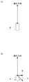
次に、操作軸157の中立位置への自動復帰動作について説明する。操作軸157が操作されない中立時は、操作軸157は上部枠体150の上面の孔172から直立した状態にあり、図5(a)に示すように、操作体158の底面と復帰部材173の内底面は復帰ばね179によって圧接されている。この状態から図5(b)に示すように、操作軸157が時計方向に傾くと、操作体158の外方に向かって曲率半径が次第に大となるような弧状部分を有する鍔部185が復帰部材173を復帰ばね179の弾性に抗して下部枠体175の支持壁177に沿って下方に移動させるように押圧する。そして、操作軸157の操作力を解除すると、復帰ばね179の付勢力によって図5(a)に示す中立状態、即ち操作軸157が直立状態に復帰する。   Next, the automatic return operation to the neutral position of the operation shaft 157 will be described. When the operation shaft 157 is not operated, the operation shaft 157 is upright from the hole 172 on the upper surface of the upper frame 150. As shown in FIG. 5A, the bottom surface of the operation body 158 and the return member 173 are arranged. The inner bottom surface is in pressure contact with a return spring 179. From this state, as shown in FIG. 5B, when the operation shaft 157 is tilted clockwise, the collar portion 185 having an arc-shaped portion whose radius of curvature gradually increases toward the outside of the operation body 158 is restored. The member 173 is pressed so as to move downward along the support wall 177 of the lower frame 175 against the elasticity of the return spring 179. When the operating force of the operating shaft 157 is released, the neutral state shown in FIG. 5A, that is, the operating shaft 157 returns to the upright state by the biasing force of the return spring 179.

以上は、多方向操作入力装置100の基本構造の説明であるが、本実施例の多方向操作入力装置100には、上記基本構造に加えて、ユーザによるアナログスティック24の操作に負荷を付与するためのアクチュエータ94が設けられている。   The above is the description of the basic structure of the multidirectional operation input device 100. In addition to the basic structure described above, the multidirectional operation input device 100 of this embodiment applies a load to the operation of the analog stick 24 by the user. An actuator 94 is provided.

図6は、操作部70に負荷を付与するためのゲームシステム1の構成を示す。第1連動部材151には、第1連動部材151の変位量(回転量)を検出するための第1回転検出部153aが連結されるとともに、第1連動部材151の動きに対して反発力またはアシスト力などの負荷を付与する第1アクチュエータ94aが連結される。第1アクチュエータ94aは、たとえば第1連動部材151の折曲部152にギアを介して連結されるモータであってよく、第1連動部材151に回転力を印加する機能をもつ。   FIG. 6 shows a configuration of the game system 1 for applying a load to the operation unit 70. The first interlocking member 151 is connected to a first rotation detecting unit 153a for detecting a displacement amount (rotation amount) of the first interlocking member 151, and a repulsive force against the movement of the first interlocking member 151 or A first actuator 94a that applies a load such as an assist force is coupled. The first actuator 94a may be, for example, a motor coupled to the bent portion 152 of the first interlocking member 151 via a gear, and has a function of applying a rotational force to the first interlocking member 151.

第2連動部材162には、第2連動部材162の変位量(回転量)を検出するための第2回転検出部153bが連結されるとともに、第2連動部材162の動きに対して反発力またはアシスト力などの負荷を付与する第2アクチュエータ94bが連結される。第2アクチュエータ94bは、たとえば第2連動部材162の腕164bにギアを介して連結されるモータであってよく、第2連動部材162に回転力を印加する機能をもつ。   The second interlocking member 162 is connected to a second rotation detector 153b for detecting a displacement (rotation amount) of the second interlocking member 162, and a repulsive force against the movement of the second interlocking member 162 or A second actuator 94b that applies a load such as an assist force is coupled. The second actuator 94b may be a motor connected to the arm 164b of the second interlocking member 162 via a gear, for example, and has a function of applying a rotational force to the second interlocking member 162.

なお、第1アクチュエータ94aおよび第2アクチュエータ94bは、電磁石などによって構成され、それぞれ第1連動部材151および第2連動部材162の回転に対して負荷(荷重)を付与してもよい。以下、第1アクチュエータ94aおよび第2アクチュエータ94bを特に区別しない場合には、まとめて「アクチュエータ94」とよぶ。   The first actuator 94a and the second actuator 94b may be configured by an electromagnet or the like, and may apply a load (load) to the rotation of the first interlocking member 151 and the second interlocking member 162, respectively. Hereinafter, the first actuator 94a and the second actuator 94b are collectively referred to as “actuator 94” unless otherwise distinguished.

ゲームシステム1は、アナログスティック24に連結する多方向操作入力装置100およびドライバIC96に加えて、ゲーム実行部202、入力受付部204、負荷情報取得部206、駆動制御部208および保持部210を有する処理部200を備える。図6において、処理部200として記載される各要素は、ハードウェア的には、CPU(Central Processing Unit)、メモリ、その他のLSIで構成することができ、ソフトウェア的には、メモリにロードされたプログラムなどによって実現される。したがって、これらの機能ブロックがハードウェアのみ、ソフトウェアのみ、またはそれらの組合せによっていろいろな形で実現できることは当業者には理解されるところであり、いずれかに限定されるものではない。   The game system 1 includes a game execution unit 202, an input reception unit 204, a load information acquisition unit 206, a drive control unit 208, and a holding unit 210 in addition to the multidirectional operation input device 100 and the driver IC 96 connected to the analog stick 24. A processing unit 200 is provided. In FIG. 6, each element described as the processing unit 200 can be configured by a CPU (Central Processing Unit), a memory, and other LSIs in terms of hardware, and loaded into the memory in terms of software. Realized by programs. Therefore, it is understood by those skilled in the art that these functional blocks can be realized in various forms by hardware only, software only, or a combination thereof, and is not limited to any one.

ゲーム実行部202が、ゲームプログラムをゲームカード76またはメモリカード78からメインメモリ64に読み出し、ゲームアプリケーションを実行する。入力受付部204は操作部70の操作を受け付ける。入力受付部204は、ユーザが操作部70から入力した操作入力を受け付け、ゲームアプリケーションが、ユーザの操作入力を用いてゲームを進行させる。アナログスティック24の操作に関して言えば、入力受付部204は、第1回転検出部153aおよび第2回転検出部153bから、アナログスティック24の操作の検出情報を取得する。これにより入力受付部204は、アナログスティック24の操作方向(傾動方向)および操作量を認識し、ゲームアプリケーションが、アナログスティック24の操作入力を用いてゲームを進行させることができる。   The game execution unit 202 reads the game program from the game card 76 or the memory card 78 to the main memory 64 and executes the game application. The input reception unit 204 receives an operation of the operation unit 70. The input receiving unit 204 receives an operation input input by the user from the operation unit 70, and the game application advances the game using the user's operation input. Regarding the operation of the analog stick 24, the input receiving unit 204 acquires detection information of the operation of the analog stick 24 from the first rotation detection unit 153a and the second rotation detection unit 153b. Thereby, the input receiving unit 204 recognizes the operation direction (tilting direction) and operation amount of the analog stick 24, and the game application can advance the game using the operation input of the analog stick 24.

ゲームシステム1において、処理部200は、ユーザがゲームにおいて選択したオブジェクトや、ゲーム中の状況に応じて、アクチュエータ94が操作部70に付与する負荷を制御する。たとえばユーザが、プレイヤキャラクタとして重量級のキャラクタを選択すると、処理部200は、アクチュエータ94に大きな負荷を生成させて操作部70の動きを重くし、一方、ユーザが軽量級のキャラクタを選択すると、処理部200は、アクチュエータ94に小さな負荷を生成させて操作部70の動きを相対的に軽くする。このように処理部200が、選択されたオブジェクトに応じて、アクチュエータ94が生成する負荷の大きさを制御することで、ユーザは、選択したキャラクタの大小に適合した重量感を指先に感じることができる。   In the game system 1, the processing unit 200 controls the load applied by the actuator 94 to the operation unit 70 in accordance with the object selected by the user in the game and the situation during the game. For example, when the user selects a heavyweight character as the player character, the processing unit 200 causes the actuator 94 to generate a large load to increase the movement of the operation unit 70, while when the user selects a lightweight character. The processing unit 200 causes the actuator 94 to generate a small load so that the operation unit 70 moves relatively lightly. As described above, the processing unit 200 controls the magnitude of the load generated by the actuator 94 in accordance with the selected object, so that the user can feel a feeling of weight suitable for the size of the selected character at the fingertip. it can.

また処理部200は、ユーザが、プレイヤキャラクタが持つ武器や道具などの装備品を選択する場合に、選択されたキャラクタおよび選択された装備品に応じて負荷の大きさを定めてもよい。たとえば、重量級キャラクタの装備品として、重い武器が選ばれると、そのキャラクタおよび装備品に応じて負荷の大きさが定められてよい。戦闘中に武器を切り替えた場合には、切り替える度に、負荷の大きさが定められてよい。このとき処理部200は、キャラクタおよび/または装備品に応じて、ユーザによる操作部70の操作方向に沿った負荷を生成してよい。   Further, when the user selects equipment such as weapons and tools possessed by the player character, the processing unit 200 may determine the magnitude of the load according to the selected character and the selected equipment. For example, when a heavy weapon is selected as the equipment for the heavyweight character, the magnitude of the load may be determined according to the character and the equipment. When a weapon is switched during a battle, the magnitude of the load may be determined each time the weapon is switched. At this time, the processing unit 200 may generate a load along the operation direction of the operation unit 70 by the user according to the character and / or the equipment.

また処理部200は、装備品を持つキャラクタのゲーム状況(ゲームシーン)に応じて、負荷の大きさを定めてもよい。このように、負荷の大きさを定める情報が、選択されたオブジェクトや、キャラクタのゲーム状況などのそれぞれに設定されており、オブジェクトが選択される度、またはゲーム状況が変化する度に、処理部200が、操作部70に与える負荷の大きさを再計算して求める。これによりキャラクタや、ゲーム状況にマッチした負荷を生成することができ、よりリアルな感覚をユーザに与えることが実現される。   The processing unit 200 may determine the magnitude of the load according to the game situation (game scene) of the character having the equipment. As described above, the information for determining the magnitude of the load is set for each of the selected object and the game situation of the character, and each time the object is selected or the game situation changes, the processing unit 200 recalculates the magnitude of the load applied to the operation unit 70. As a result, it is possible to generate a load that matches the character and the game situation, and to realize a more realistic feeling to the user.

なお処理部200は、負荷の大きさのみならず、操作部70に対して負荷を付与する方向を定めてもよい。たとえば処理部200は、ゲーム状況に応じて、負荷を付与する方向を定める。プレイヤキャラクタが、操作部70の操作方向に進行するゲームにおいて、プレイヤキャラクタの進行方向に対して横風が吹いているようなゲームシーンを想定すると、処理部200は、この横風を、キャラクタの進行方向に対して横向きに作用する操作部70への外力として処理し、この横風に相当する外力を、操作部70のユーザ操作とは無関係に、操作部70に付与してもよい。このとき処理部200は、ユーザによる操作部70の操作に対する負荷と、ゲーム状況に応じて付与される負荷との合力を、操作部70に付与させるようにアクチュエータ94を制御する。なお操作部70が操作されておらず、キャラクタが操作部70のユーザ操作により動かされていない場合には、処理部200は合力として、ゲーム状況に応じた負荷(横風による負荷)のみを操作部70に付与し、この場合には、ゲーム中において、ユーザが操作部70を操作していないにも関わらず、操作部70が横方向に傾動される。これによりゲームにおいては、プレイヤキャラクタが横風を受けて、横方向に、じりじりと動くようなシーンが形成されることになる。   Note that the processing unit 200 may determine not only the magnitude of the load but also the direction in which the load is applied to the operation unit 70. For example, the processing unit 200 determines the direction in which the load is applied according to the game situation. In a game in which the player character progresses in the operation direction of the operation unit 70, assuming a game scene in which a crosswind is blowing with respect to the player character's travel direction, the processing unit 200 uses the crosswind as the character's travel direction. However, the external force corresponding to the cross wind may be applied to the operation unit 70 regardless of the user operation of the operation unit 70. At this time, the processing unit 200 controls the actuator 94 so as to cause the operation unit 70 to apply the resultant force of the load on the operation of the operation unit 70 by the user and the load applied according to the game situation. When the operation unit 70 is not operated and the character is not moved by a user operation of the operation unit 70, the processing unit 200 uses only the load according to the game situation (load due to cross wind) as a resultant force. In this case, the operation unit 70 is tilted in the horizontal direction even though the user does not operate the operation unit 70 during the game. Thus, in the game, a scene is formed in which the player character receives a crosswind and moves in the horizontal direction.

処理部200において負荷情報取得部206は、ゲームアプリケーションから、ユーザにより選択されたオブジェクトに対応する情報(負荷情報)を取得し、保持部210に保持させる。駆動制御部208は、ドライバIC96を介してアクチュエータ94を制御する。駆動制御部208は、ドライバIC96から出力する電圧値を指定し、ドライバIC96は、制御信号として電圧信号をアクチュエータ94に供給して、アクチュエータ94を駆動する。ここでゲームアプリケーションから供給される負荷情報は、駆動制御部208がアクチュエータ94により生成する負荷を特定するための情報であればよい。駆動制御部208は、負荷情報から、アクチュエータ94で生成させる負荷の大きさおよび方向を定めて、アクチュエータ94の駆動を制御する。   In the processing unit 200, the load information acquisition unit 206 acquires information (load information) corresponding to the object selected by the user from the game application, and causes the holding unit 210 to hold the information. The drive control unit 208 controls the actuator 94 via the driver IC 96. The drive control unit 208 specifies the voltage value output from the driver IC 96, and the driver IC 96 supplies the voltage signal to the actuator 94 as a control signal to drive the actuator 94. Here, the load information supplied from the game application may be information for specifying the load generated by the actuator 94 by the drive control unit 208. The drive control unit 208 controls the drive of the actuator 94 by determining the magnitude and direction of the load generated by the actuator 94 from the load information.

負荷情報には、操作部70の操作方向に沿った負荷の大きさを特定するための情報と、操作部70の操作方向とは独立した方向に沿った負荷の大きさを特定するための情報とが存在する。いずれの情報も、負荷の大きさを特定する点では共通しているが、前者の情報は、ユーザによる操作部70の操作に対して重いまたは軽い操作感を提供するために利用され、一方で後者の情報は、操作部70の操作方向に対して別の方向に作用しうる負荷の付与方向も定めることから、操作部70の操作に対する外乱成分として利用される。本実施例では、以下に示すように、オブジェクトに関して設定される負荷情報は、操作部70の操作方向に沿った負荷の大きさを特定する前者の情報に相当し、ゲーム状況に応じて設定される負荷情報は、操作方向とは独立した負荷の付与方向を定める後者の情報に相当する。   The load information includes information for specifying the magnitude of the load along the operation direction of the operation unit 70 and information for specifying the magnitude of the load along a direction independent of the operation direction of the operation unit 70. And exist. Both types of information are common in that the magnitude of the load is specified, but the former information is used to provide a heavy or light operational feeling for the operation of the operation unit 70 by the user, The latter information is used as a disturbance component for the operation of the operation unit 70 because it also determines the load application direction that can act in another direction with respect to the operation direction of the operation unit 70. In the present embodiment, as will be described below, the load information set for the object corresponds to the former information for specifying the magnitude of the load along the operation direction of the operation unit 70, and is set according to the game situation. The load information corresponds to the latter information that determines the load application direction independent of the operation direction.

図7は、表示装置20に表示されるキャラクタ選択画面を示す。ユーザは方向キー23などを操作して、プレイヤキャラクタを選択する。ここでキャラクタ220a、220bは重量級キャラクタ、キャラクタ220c、220dは中量級キャラクタ、キャラクタ220e、220fは軽量級キャラクタを示す。   FIG. 7 shows a character selection screen displayed on the display device 20. The user operates the direction key 23 or the like to select a player character. Here, characters 220a and 220b are heavyweight characters, characters 220c and 220d are medium weight characters, and characters 220e and 220f are light weight characters.

図8(a)は、キャラクタと負荷レベルの対応表を示す。この対応表は、ゲームプログラムに組み込まれており、キャラクタ名(ないしはキャラクタID)に、その属性情報、具体的にはキャラクタのカテゴリ、キャラクタに設定された負荷レベルが対応付けられている。たとえばキャラクタ220aは、属性情報として、「重量級」、「負荷レベル15」を設定されており、キャラクタ220cは、属性情報として、「中量級」、「負荷レベル10」を設定されている。   FIG. 8A shows a correspondence table between characters and load levels. This correspondence table is incorporated in the game program, and the attribute information, specifically, the category of the character and the load level set for the character are associated with the character name (or character ID). For example, “weight class” and “load level 15” are set as the attribute information for the character 220a, and “medium class” and “load level 10” are set as the attribute information for the character 220c.

以下では、アクチュエータ94が、ユーザのアナログスティック24の操作方向に沿った外力を生成する例について説明する。
駆動制御部208は、ドライバIC96を介してアクチュエータ94からアナログスティック24に供給する負荷を、−19レベル〜20レベルの40段階で制御する。マイナスの負荷レベルは、アクチュエータ94がアシストトルクを生成することを意味し、プラスの負荷レベルは、アクチュエータ94が抵抗トルクを生成することを意味し、0の負荷レベルは、アクチュエータ94がトルクを生成しないことを意味する。したがって負荷レベルがプラスであれば、アナログスティック24には反発力が印加されて、操作が重くなり、また、負荷レベルがマイナスであれば、アナログスティック24にはアシスト力が印加されて、操作が軽くなる。なお、プラスのレベル値が大きいほど、発生する抵抗トルクは大きくなり、マイナスのレベル値が大きいほど、発生するアシストトルクは大きくなる。
Hereinafter, an example in which the actuator 94 generates an external force along the operation direction of the analog stick 24 of the user will be described.
The drive control unit 208 controls the load supplied from the actuator 94 to the analog stick 24 via the driver IC 96 in 40 levels from -19 level to 20 level. A negative load level means that the actuator 94 generates assist torque, a positive load level means that the actuator 94 generates resistance torque, and a zero load level means that the actuator 94 generates torque. It means not. Therefore, if the load level is positive, a repulsive force is applied to the analog stick 24 and the operation becomes heavy. If the load level is negative, an assist force is applied to the analog stick 24 and the operation is performed. It becomes lighter. The greater the positive level value, the greater the generated resistance torque, and the greater the negative level value, the greater the generated assist torque.

ゲームアプリケーションは、ユーザがキャラクタを選択すると、図8(a)に示す対応表をもとに、ユーザにより選択されたキャラクタに対応する負荷レベルを、負荷情報として処理部200に供給する。処理部200において負荷情報取得部206が負荷情報を取得し、駆動制御部208は、負荷情報取得部206が取得した負荷情報にしたがって、アクチュエータ94を制御する。なお保持部210は、負荷情報取得部206が取得したキャラクタに関する負荷情報を保持する。   When the user selects a character, the game application supplies a load level corresponding to the character selected by the user to the processing unit 200 as load information based on the correspondence table shown in FIG. In the processing unit 200, the load information acquisition unit 206 acquires load information, and the drive control unit 208 controls the actuator 94 according to the load information acquired by the load information acquisition unit 206. The holding unit 210 holds the load information related to the character acquired by the load information acquisition unit 206.

たとえばキャラクタ220aが選択された場合、駆動制御部208は、アナログスティック24の操作に対して、負荷レベル15に対応する抵抗トルクをアクチュエータ94から生成させる。保持部210は、ゲームアプリケーションから提供される負荷レベルと、負荷レベルに応じたトルク値との対応表を保持しており、駆動制御部208は、その対応表にしたがって、負荷レベルに応じたトルクをアクチュエータ94から生成させるようにする。なお、この対応表には、負荷レベルと、負荷レベルに応じたトルクを生成するためにアクチュエータ94に供給する電圧値とが対応付けられていてもよい。また駆動制御部208は、負荷情報にしたがって、第1アクチュエータ94aおよび第2アクチュエータ94bのそれぞれに供給するべき電圧値を演算により算出してもよい。   For example, when the character 220 a is selected, the drive control unit 208 causes the actuator 94 to generate a resistance torque corresponding to the load level 15 in response to the operation of the analog stick 24. The holding unit 210 holds a correspondence table between a load level provided from the game application and a torque value corresponding to the load level, and the drive control unit 208 performs torque according to the load level according to the correspondence table. Is generated from the actuator 94. In this correspondence table, a load level may be associated with a voltage value supplied to the actuator 94 in order to generate torque according to the load level. Moreover, the drive control part 208 may calculate the voltage value which should be supplied to each of the 1st actuator 94a and the 2nd actuator 94b by a calculation according to load information.

このとき駆動制御部208は、アナログスティック24が傾動された方向の逆向きに、抵抗トルクを発生させる。そのため入力受付部204が、アナログスティック24の傾動方向を検出すると、その傾動方向を駆動制御部208に供給し、駆動制御部208は、その傾動方向の逆向きに、負荷レベル15に対応する抵抗トルクを発生させるように、第1アクチュエータ94aおよび第2アクチュエータ94bの駆動を制御する。このように駆動制御部208は、入力受付部204が受け付けたアナログスティック24の操作に対して負荷を付与させるようにアクチュエータ94を制御する。   At this time, the drive control unit 208 generates resistance torque in the direction opposite to the direction in which the analog stick 24 is tilted. Therefore, when the input receiving unit 204 detects the tilt direction of the analog stick 24, the tilt receiving direction is supplied to the drive control unit 208, and the drive control unit 208 has a resistance corresponding to the load level 15 in the opposite direction of the tilt direction. The driving of the first actuator 94a and the second actuator 94b is controlled so as to generate torque. In this way, the drive control unit 208 controls the actuator 94 so as to apply a load to the operation of the analog stick 24 received by the input receiving unit 204.

また、たとえばキャラクタ220eが選択された場合には、駆動制御部208は、アナログスティック24の操作に対して、負荷レベル5に対応する抵抗トルクをアクチュエータ94から生成させる。キャラクタ220aとキャラクタ220eが選択された場合を比較すると、重量級であるキャラクタ220aが選択された場合には、負荷レベル15に対応する抵抗トルクが生成される一方で、キャラクタ220eが選択された場合には、負荷レベル5に対応する抵抗トルクが生成される。したがって、重量級のキャラクタが選択された場合には、アナログスティック24に印加される反発力が大きく、重い操作感をユーザに提供でき、一方で、軽量級のキャラクタが選択された場合には、アナログスティック24に印加される反発力が相対的に小さく、相対的に軽い操作感をユーザに提供できる。   For example, when the character 220 e is selected, the drive control unit 208 causes the actuator 94 to generate a resistance torque corresponding to the load level 5 in response to the operation of the analog stick 24. Comparing the case where the character 220a and the character 220e are selected, when the heavyweight character 220a is selected, the resistance torque corresponding to the load level 15 is generated while the character 220e is selected. A resistance torque corresponding to the load level 5 is generated. Therefore, when a heavyweight character is selected, the repulsive force applied to the analog stick 24 is large, and a heavy operational feeling can be provided to the user. On the other hand, when a lightweight character is selected, The repulsive force applied to the analog stick 24 is relatively small, and a relatively light operational feeling can be provided to the user.

ユーザは、キャラクタ220を選択した後、キャラクタが持つ装備品を選択する。この選択のタイミングは、キャラクタ220の選択直後であってもよく、また、ゲームプレイ中の任意のタイミングであってもよい。たとえばユーザは、敵キャラクタとの戦闘中に、武器を交換してもよい。   After selecting the character 220, the user selects the equipment that the character has. This selection timing may be immediately after the character 220 is selected, or may be any timing during game play. For example, the user may exchange weapons during a battle with an enemy character.

図8(b)は、装備品名と負荷レベルの対応表を示す。この対応表は、ゲームプログラムに組み込まれており、装備品と、その属性情報、具体的には装備品のカテゴリ、装備品に設定された負荷レベルが対応付けられている。たとえば武器Aは、属性情報として、「大」、「負荷レベル5」を設定されており、武器Gは、属性情報として、「小」、「負荷レベル−10」を設定されている。   FIG. 8B shows a correspondence table between equipment names and load levels. This correspondence table is incorporated in the game program, and the equipment is associated with the attribute information, specifically, the equipment category and the load level set for the equipment. For example, weapon A has “large” and “load level 5” set as attribute information, and weapon G has “small” and “load level −10” set as attribute information.

ゲームアプリケーションは、ユーザが装備品(武器)を選択すると、図8(b)に示す対応表をもとに、ユーザにより選択された装備品に対応する負荷レベルを、負荷情報として処理部200に供給する。処理部200において負荷情報取得部206が負荷情報を取得し、駆動制御部208は、負荷情報取得部206が取得した負荷情報にしたがって、アクチュエータ94を制御する。   When the user selects the equipment (weapon), the game application uses the load level corresponding to the equipment selected by the user based on the correspondence table shown in FIG. Supply. In the processing unit 200, the load information acquisition unit 206 acquires load information, and the drive control unit 208 controls the actuator 94 according to the load information acquired by the load information acquisition unit 206.

ここで負荷情報取得部206は、既に、選択されたキャラクタに対応する負荷情報を取得しており、それに加えて、さらに装備品に対応する負荷情報を取得することになる。駆動制御部208は、負荷情報取得部206から、装備品に対応する負荷情報の供給を受けると、既に受け取っているキャラクタに対応する負荷情報と、装備品に対応する負荷情報とにしたがって、アクチュエータ94を制御する。このとき保持部210は、選択されたキャラクタに対応する負荷情報と、選択された装備品に対応する負荷情報とを保持する。   Here, the load information acquisition unit 206 has already acquired the load information corresponding to the selected character, and additionally acquires the load information corresponding to the equipment. When the drive control unit 208 receives supply of load information corresponding to the equipment from the load information acquisition unit 206, the drive control unit 208 operates according to the load information corresponding to the character already received and the load information corresponding to the equipment. 94 is controlled. At this time, the holding unit 210 holds load information corresponding to the selected character and load information corresponding to the selected equipment.

たとえば、キャラクタ220aが選択されている場合、保持部210は、キャラクタに対応する負荷情報として、負荷レベル15を示す負荷情報を保持している。ここで武器Aが選択されると、駆動制御部208は、武器Aに対応する負荷レベル5を示す負荷情報を提供される。駆動制御部208は、この2つの負荷情報にもとづいてアクチュエータ94を制御するが、このとき単純に負荷レベル同士を加算して、新たな負荷レベルを導出してもよい。この例では、負荷レベル15と負荷レベル5を加算して、負荷レベル20が導出される。これにより駆動制御部208は、保持部210に保持された負荷レベルとトルク値との対応表を参照して、負荷レベル20に応じた抵抗トルクをアクチュエータ94から生成させるようにする。なお、複数の負荷レベルを合算することで、その計算値が、負荷レベルの許容範囲(−19から+20の範囲)を超えるような場合には、その許容範囲の最大値を負荷レベルとして導出してもよい。   For example, when the character 220a is selected, the holding unit 210 holds load information indicating the load level 15 as load information corresponding to the character. When the weapon A is selected here, the drive control unit 208 is provided with load information indicating the load level 5 corresponding to the weapon A. The drive control unit 208 controls the actuator 94 based on the two pieces of load information. At this time, the load level may be simply added to derive a new load level. In this example, the load level 15 and the load level 5 are added to derive the load level 20. Accordingly, the drive control unit 208 refers to the correspondence table between the load level and the torque value held in the holding unit 210 and causes the actuator 94 to generate a resistance torque corresponding to the load level 20. In addition, when the calculated value exceeds the allowable range of the load level (range of −19 to +20) by adding a plurality of load levels, the maximum value of the allowable range is derived as the load level. May be.

たとえば、キャラクタ220fが選択されている場合、保持部210は、キャラクタに対応する負荷情報として、負荷レベル5を示す負荷情報を保持している。ここで武器Gが選択されると、駆動制御部208は、武器Gに対応する負荷レベル−10を示す負荷情報を提供される。駆動制御部208は、この2つの負荷情報にもとづいて新たな負荷レベルを導出するが、この例では、負荷レベル5と負荷レベル−10を加算して、負荷レベル−5が導出される。これにより駆動制御部208は、保持部210に保持された負荷レベルとトルク値との対応表を参照して、負荷レベル−5に応じたアシストトルクをアクチュエータ94から生成させるようにする。このとき、ユーザによるアナログスティック24の傾動操作は、アクチュエータ94によりアシストされるため、アナログスティック24の操作感は、非常に軽くなる。   For example, when the character 220f is selected, the holding unit 210 holds load information indicating the load level 5 as load information corresponding to the character. When the weapon G is selected here, the drive control unit 208 is provided with load information indicating the load level −10 corresponding to the weapon G. The drive control unit 208 derives a new load level based on the two pieces of load information. In this example, the load level-5 is derived by adding the load level 5 and the load level-10. Accordingly, the drive control unit 208 refers to the correspondence table between the load level and the torque value held in the holding unit 210 and causes the actuator 94 to generate assist torque according to the load level-5. At this time, since the tilting operation of the analog stick 24 by the user is assisted by the actuator 94, the operation feeling of the analog stick 24 becomes very light.

このように、負荷情報取得部206が複数のオブジェクト、ここではキャラクタと装備品に対応する負荷情報を取得すると、保持部210が、それぞれのオブジェクトに対応する負荷情報を保持し、駆動制御部208が、その複数のオブジェクトの組合せに応じた負荷レベルを算出することで、アナログスティック24に印加するトルクを適宜調整できる。たとえば重量級のキャラクタが、小さい武器を使用する場合には、武器を使用しない場合と比べて、操作が若干軽くなり、一方で、大きい武器を使用する場合には、武器を使用しない場合と比べて、操作がさらに重くなる。このように駆動制御部208が、きめ細かにアナログスティック24に印加する負荷(荷重)を調整することで、ユーザは、選択した複数のオブジェクトに適合した操作感で、アナログスティック24を操作できる。   As described above, when the load information acquisition unit 206 acquires load information corresponding to a plurality of objects, here, characters and equipment, the holding unit 210 holds load information corresponding to each object, and the drive control unit 208. However, the torque applied to the analog stick 24 can be appropriately adjusted by calculating the load level corresponding to the combination of the plurality of objects. For example, when a heavyweight character uses a small weapon, the operation is slightly lighter than when a weapon is not used. On the other hand, when a large weapon is used, the operation does not use a weapon. The operation becomes even heavier. As described above, the drive control unit 208 finely adjusts the load (load) applied to the analog stick 24, so that the user can operate the analog stick 24 with an operation feeling suitable for a plurality of selected objects.

なお、ユーザが複数のオブジェクトを選択した場合、ゲームアプリケーションが、各オブジェクトに対応する負荷レベルを加算して、負荷レベルを合計し、その合計した負荷レベルを処理部200に供給してもよい。このようにゲームアプリケーションが、複数のオブジェクトの組合せに対応する負荷レベルの算出機能を有している場合には、駆動制御部208は、算出された負荷レベルをもとに発生トルクを制御すればよい。ゲームアプリケーションは、複数のオブジェクトの組合せと、負荷レベルの対応表を有し、その対応表を参照して、複数のオブジェクトに応じた負荷レベルを処理部200に供給してもよい。   When the user selects a plurality of objects, the game application may add the load levels corresponding to the objects, sum the load levels, and supply the total load level to the processing unit 200. As described above, when the game application has a load level calculation function corresponding to a combination of a plurality of objects, the drive control unit 208 controls the generated torque based on the calculated load level. Good. The game application may include a combination table of a plurality of objects and a load level correspondence table, and supply the load level corresponding to the plurality of objects to the processing unit 200 with reference to the correspondence table.

保持部210は、それぞれのオブジェクトに対応する負荷レベルを保持しているが、たとえばユーザが装備品を変更し、負荷情報取得部206が、変更された装備品に対応する負荷レベルを取得すると、保持部210は、保持している装備品に対応する負荷レベルを、新たに取得された負荷レベルで上書き更新する。このように保持部210は、同種のオブジェクトの負荷レベルについては、負荷情報取得部206が新たな負荷レベルを取得すると、その都度上書き更新する。これにより駆動制御部208は、更新された現在のオブジェクトの状態に適合した負荷をアナログスティック24に付与することができる。   The holding unit 210 holds the load level corresponding to each object. For example, when the user changes the equipment, and the load information acquisition unit 206 acquires the load level corresponding to the changed equipment, The holding unit 210 overwrites and updates the load level corresponding to the held equipment with the newly acquired load level. As described above, the holding unit 210 overwrites and updates the load level of the same type of object every time the load information acquisition unit 206 acquires a new load level. As a result, the drive control unit 208 can give the analog stick 24 a load suitable for the updated state of the current object.

なお、これは装備品が変更された場合であり、キャラクタが複数の装備品を持つことができるのであれば、保持部210は、キャラクタが持っている複数の装備品に対応する負荷レベルを保持する。つまり保持部210は、キャラクタが現在持っている装備品に対応する負荷レベルを全て保持し、駆動制御部208が、その全ての装備品に対応する負荷レベルを用いて、アクチュエータ94の発生トルクを導出する。なお、この場合、駆動制御部208は、全ての装備品に対応する負荷レベルを利用するのではなく、最も大きい負荷レベルのみを用いて、アクチュエータ94の発生トルクを導出してもよい。   Note that this is a case where the equipment is changed, and if the character can have a plurality of equipment, the holding unit 210 holds the load level corresponding to the plurality of equipment possessed by the character. To do. That is, the holding unit 210 holds all the load levels corresponding to the equipment currently possessed by the character, and the drive control unit 208 uses the load levels corresponding to all the equipment to generate the torque generated by the actuator 94. To derive. In this case, the drive control unit 208 may derive the generated torque of the actuator 94 using only the largest load level instead of using the load level corresponding to all the equipment.

図9は、キャラクタと負荷レベルの対応表の別の例を示す。この対応表は、ゲームプログラムに組み込まれており、キャラクタ名と、その属性情報、具体的にはキャラクタのカテゴリ、キャラクタに設定された負荷レベルが対応付けられている。ここで設定されている負荷レベルは、中量級の負荷レベルを基準とした差分値である。この例では前提として、中量級のキャラクタの基準負荷レベルが10と設定されており、保持部210は、基準負荷レベルを保持し、駆動制御部208は、この基準負荷レベルにしたがったアクチュエータ94の制御を実行している。つまり、負荷情報取得部206が負荷情報を取得しない状態では、駆動制御部208は、アクチュエータ94が負荷レベル10に対応する抵抗トルクを生成するように、ドライバIC96を制御している。   FIG. 9 shows another example of a correspondence table between characters and load levels. This correspondence table is incorporated in the game program, and character names are associated with attribute information thereof, specifically, character categories and load levels set for the characters. The load level set here is a difference value based on the medium-class load level. In this example, as a premise, the reference load level of the medium-weight character is set to 10, the holding unit 210 holds the reference load level, and the drive control unit 208 uses the actuator 94 according to this reference load level. Running control. That is, in a state where the load information acquisition unit 206 does not acquire load information, the drive control unit 208 controls the driver IC 96 so that the actuator 94 generates a resistance torque corresponding to the load level 10.

ゲームアプリケーションは、ユーザがキャラクタを選択すると、図9に示す対応表をもとに、ユーザにより選択されたキャラクタに対応する差分負荷レベルを、負荷情報として処理部200に供給する。処理部200において負荷情報取得部206が負荷情報を取得し、駆動制御部208は、負荷情報取得部206が取得した負荷情報にしたがって、アクチュエータ94を制御する。   When the user selects a character, the game application supplies a differential load level corresponding to the character selected by the user to the processing unit 200 as load information based on the correspondence table shown in FIG. In the processing unit 200, the load information acquisition unit 206 acquires load information, and the drive control unit 208 controls the actuator 94 according to the load information acquired by the load information acquisition unit 206.

たとえばキャラクタ220aが選択された場合、駆動制御部208は、基準負荷レベル10と、キャラクタ220aに対応する負荷レベル5を加算して、合算した負荷レベル15を導出し、負荷レベル15に対応する抵抗トルクをアクチュエータ94から生成させる。またキャラクタ220fが選択された場合、駆動制御部208は、基準負荷レベル10と、キャラクタ220fに対応する負荷レベル−5を加算して、合算した負荷レベル5を導出し、負荷レベル5に対応する抵抗トルクをアクチュエータ94から生成させる。このとき、抵抗トルクは、基準負荷レベルに対応する抵抗トルクよりも小さくなり、したがってユーザは、軽量級のキャラクタを選択したことで、操作が軽くなったことを認識できるようになる。   For example, when the character 220a is selected, the drive control unit 208 adds the reference load level 10 and the load level 5 corresponding to the character 220a to derive the combined load level 15, and the resistance corresponding to the load level 15 is obtained. Torque is generated from the actuator 94. When the character 220f is selected, the drive control unit 208 adds the reference load level 10 and the load level -5 corresponding to the character 220f to derive the combined load level 5, and corresponds to the load level 5. A resistance torque is generated from the actuator 94. At this time, the resistance torque becomes smaller than the resistance torque corresponding to the reference load level, and thus the user can recognize that the operation has become lighter by selecting the lightweight character.

以上は、1つ以上の選択したオブジェクトに応じて、アクチュエータ94が生成するトルクが制御される例について説明したが、駆動制御部208は、ゲームの状況に応じて、アクチュエータ94が生成するトルクを調整してもよい。ゲームアプリケーションは、ゲームの状況に対応付けられた負荷レベルを処理部200に供給する。たとえばゲームアプリケーションは、プレイヤキャラクタが悪路を進んでいるときには、抵抗トルクが大きくなる(又は、アシストトルクが小さくなる)ような負荷レベルを処理部200に供給し、またプレイヤキャラクタが氷上を滑っているときには、抵抗トルクが小さくなる(又は、アシストトルクが大きくなる)ような負荷レベルを処理部200に供給する。駆動制御部208は、現在の負荷レベルに、新たに取得した負荷レベルを加算し、加算した負荷レベルをもとに、アクチュエータ94の制御を行う。   In the above, the example in which the torque generated by the actuator 94 is controlled according to one or more selected objects has been described. However, the drive control unit 208 determines the torque generated by the actuator 94 according to the game situation. You may adjust. The game application supplies the processing unit 200 with a load level associated with the game situation. For example, the game application supplies a load level that increases the resistance torque (or decreases the assist torque) to the processing unit 200 when the player character is traveling on a rough road, and the player character slides on the ice. When the load is on, a load level that decreases the resistance torque (or increases the assist torque) is supplied to the processing unit 200. The drive control unit 208 adds the newly acquired load level to the current load level, and controls the actuator 94 based on the added load level.

このように本実施例のゲームシステム1においては、ユーザが選択した1つ以上のオブジェクトに設定された負荷レベルや、ゲームの状況に設定された負荷レベルを用いて、アナログスティック24に付与する負荷の大きさが定められる。このように負荷を、ユーザによる選択時および/または所定のゲーム状況時に適切に調整することで、ゲームの臨場感を大きく高めることが可能となる。なお以上は、負荷の印加方向が、アナログスティック24の操作方向と逆向き、または同じ向きとして説明しているが、駆動制御部208は、アナログスティック24の操作方向と異なる向きに外力を生成することも可能であり、それについては後述する。   As described above, in the game system 1 according to the present embodiment, the load applied to the analog stick 24 using the load level set for one or more objects selected by the user or the load level set for the game situation. The size of is determined. In this way, by appropriately adjusting the load at the time of selection by the user and / or a predetermined game situation, it is possible to greatly enhance the realistic sensation of the game. In the above description, the load application direction is described as being opposite or the same as the operation direction of the analog stick 24, but the drive control unit 208 generates an external force in a direction different from the operation direction of the analog stick 24. This is also possible and will be described later.

なおゲームアプリケーションが、負荷情報として、負荷レベルを処理部200に提供することを説明したが、負荷レベル以外の属性情報、たとえばキャラクタの重さに関する情報や、装備品の大きさに関する情報を、負荷情報として処理部200に提供してもよい。このとき保持部210は、提供された属性情報と、負荷レベル(ないしは生成トルクまたはトルクに対応する電圧値)とを対応付けた対応表を保持しており、この対応表にしたがってアクチュエータ94を制御してもよい。このようにゲームアプリケーションが処理部200に提供する負荷情報は、アクチュエータ94が生成する外力の大きさ(レベル)を直接特定する「負荷レベル」であってもよいが、生成する外力の大きさを間接的に特定する情報であってもよく、いずれにしても、アクチュエータ94に付与する電圧値を導き出すための情報であればよい。そのため処理部200において、オブジェクトIDと負荷レベルとを対応付けた対応表が保持されているのであれば、ゲームアプリケーションは、負荷情報として、選択されたオブジェクトのオブジェクトIDを処理部200に提供してもよい。なお、保持部210に保持される対応表は、ゲーム起動時に、ゲームアプリケーションから処理部200に提供されてもよい。   In addition, although it demonstrated that a game application provides a load level to the process part 200 as load information, attribute information other than a load level, for example, the information regarding the weight of a character, the information regarding the magnitude | size of an equipment, Information may be provided to the processing unit 200 as information. At this time, the holding unit 210 holds a correspondence table in which the provided attribute information is associated with the load level (or the generated torque or the voltage value corresponding to the torque), and controls the actuator 94 according to this correspondence table. May be. As described above, the load information provided to the processing unit 200 by the game application may be a “load level” that directly specifies the magnitude (level) of the external force generated by the actuator 94. Information that is indirectly specified may be used, and in any case, information for deriving a voltage value to be applied to the actuator 94 may be used. Therefore, if the processing unit 200 holds a correspondence table in which object IDs and load levels are associated with each other, the game application provides the processing unit 200 with the object ID of the selected object as load information. Also good. Note that the correspondence table held in the holding unit 210 may be provided from the game application to the processing unit 200 when the game is activated.

負荷レベルを設定するゲーム状況としては、様々なものが考えられ、ゲームシーンに応じて適宜ゲームメーカにより採用されてよい。たとえば呪文の効力により、キャラクタにかかる重力が軽くなるゲームにおいては、呪文が切れかけると、徐々に抵抗トルクが大きくなるようにアクチュエータ94が制御されてもよい。また、キャラクタがスカイダイビングをするゲームシーンにおいては、パラシュートを開くまでは抵抗トルクが小さく(またはアシストトルクを印加し)、パラシュートを開くと、抵抗トルクが大きくなるようにアクチュエータ94が制御されてもよい。このように、ゲームシーンやキャラクタなどのゲーム状況に応じて、適切な負荷情報をゲームプログラムが処理部200に出力するように構成されることで、臨場感を高めたゲームが実現される。   Various game situations for setting the load level are conceivable and may be appropriately adopted by the game maker according to the game scene. For example, in a game where the gravity applied to the character is lightened by the effect of the spell, the actuator 94 may be controlled so that the resistance torque gradually increases when the spell is cut. Also, in a game scene where the character is skydiving, even if the actuator 94 is controlled so that the resistance torque is small (or assist torque is applied) until the parachute is opened, and the parachute is opened, the resistance torque is increased. Good. As described above, the game program is configured to output appropriate load information to the processing unit 200 in accordance with the game situation such as a game scene or a character, thereby realizing a game with enhanced realism.

以上の例において、負荷情報は、負荷レベルを直接的または間接的に特定するための情報であり、すなわちアクチュエータ94で生成する外力の大きさを定めるための情報である。アナログスティック24に印加する外力の作用方向は、アナログスティック24の操作方向に沿って定められ、アナログスティック24が中立位置から所定方向に傾動されると、駆動制御部208は、アナログスティック24の傾動方向に沿った方向に、アクチュエータ94により外力を生成させ、またアナログスティック24が傾動した状態から回転させられると、駆動制御部208は、アナログスティック24の回転方向に沿った方向に、アクチュエータ94により外力を生成させる。   In the above example, the load information is information for specifying the load level directly or indirectly, that is, information for determining the magnitude of the external force generated by the actuator 94. The acting direction of the external force applied to the analog stick 24 is determined along the operation direction of the analog stick 24. When the analog stick 24 is tilted in a predetermined direction from the neutral position, the drive control unit 208 tilts the analog stick 24. When the external force is generated by the actuator 94 in the direction along the direction and the analog stick 24 is rotated from the tilted state, the drive control unit 208 is driven by the actuator 94 in the direction along the rotation direction of the analog stick 24. Generate external force.

以下、アナログスティック24の傾動方向に沿った方向に、アクチュエータ94が外力を生成したときの負荷について説明する。本実施例の多方向操作入力装置100においては、復帰ばね179が設けられており(図4参照)、復帰ばね179は、操作軸157すなわちアナログスティック24が傾動されると、中立状態に復帰する方向に復元力を生成する。   Hereinafter, a load when the actuator 94 generates an external force in a direction along the tilting direction of the analog stick 24 will be described. In the multidirectional operation input device 100 of this embodiment, a return spring 179 is provided (see FIG. 4), and the return spring 179 returns to the neutral state when the operation shaft 157, that is, the analog stick 24 is tilted. Generate a restoring force in the direction.

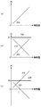
図10(a)は、アナログスティック24の傾動量と、復帰ばね179に生じる力の関係を模式的に示す。なお、ここではアナログスティック24の傾動量と、復帰ばね179の伸び量とが比例関係にあるものとして、ばね復元力230を示している。
駆動制御部208は、復帰ばね179により生成される復元力を加味して、アナログスティック24に付与する負荷を生成する。以下の例では駆動制御部208が、アプリケーションから提供される負荷情報に対応する反発力がアナログスティック24からユーザの指先に伝わるように、ドライバIC96からアクチュエータ94に供給する制御信号を調整する。
FIG. 10A schematically shows the relationship between the tilt amount of the analog stick 24 and the force generated in the return spring 179. Here, the spring restoring force 230 is shown on the assumption that the tilt amount of the analog stick 24 and the extension amount of the return spring 179 are in a proportional relationship.
The drive control unit 208 generates a load to be applied to the analog stick 24 in consideration of the restoring force generated by the return spring 179. In the following example, the drive control unit 208 adjusts the control signal supplied from the driver IC 96 to the actuator 94 so that the repulsive force corresponding to the load information provided from the application is transmitted from the analog stick 24 to the user's fingertip.

図10(b)は、アナログスティック24の操作に対する反発力F1を生成する際に、アクチュエータ94により生成されるアクチュエータ生成力232を示す。駆動制御部208は、復帰ばね179によるばね復元力230と、アクチュエータ94によるアクチュエータ生成力232との合力が、反発力F1である抵抗負荷234となるように、傾動量に応じてドライバIC96を制御する。駆動制御部208は、傾動量の増加に応じて増加するばね復元力230に対して、アクチュエータ生成力232を傾動量の増加に応じて減少させて、いずれの傾動量においても、一定の反発力F1がアナログスティック24に供給されるようにドライバIC96の制御信号を調整する。   FIG. 10B shows the actuator generating force 232 generated by the actuator 94 when generating the repulsive force F <b> 1 with respect to the operation of the analog stick 24. The drive control unit 208 controls the driver IC 96 according to the amount of tilt so that the resultant force of the spring restoring force 230 by the return spring 179 and the actuator generating force 232 by the actuator 94 becomes the resistance load 234 that is the repulsive force F1. To do. The drive control unit 208 reduces the actuator generating force 232 according to the increase in the tilt amount with respect to the spring restoring force 230 that increases as the tilt amount increases, and a constant repulsive force at any tilt amount. The control signal of the driver IC 96 is adjusted so that F1 is supplied to the analog stick 24.

図10(c)は、アナログスティック24の操作に対する反発力F2を生成する際に、アクチュエータ94により生成されるアクチュエータ生成力236を示す。これは図10(b)と比較すると、反発力F2が、復帰ばね179が最大傾動時におけるばね復元力230よりも小さい場合であり、駆動制御部208は、復帰ばね179によるばね復元力230と、アクチュエータ94によるアクチュエータ生成力236との合力が、反発力F2である抵抗負荷238となるように、傾動量に応じてドライバIC96を制御する。駆動制御部208は、傾動量の増加に応じて増加するばね復元力230に対して、アクチュエータ生成力236を傾動量の増加に応じて減少させて、いずれの傾動量においても、一定の反発力F2がアナログスティック24に供給されるようにドライバIC96の制御信号を調整する。図10(c)に示すように、アナログスティック24の傾動量がLを超えると、駆動制御部208は、アクチュエータ94に供給する制御信号を正負反転させる。このようにアクチュエータ94は、復帰ばね179の復元力とあいまって、アナログスティック24の操作に対して反発力F2を付与する。   FIG. 10C shows the actuator generating force 236 generated by the actuator 94 when generating the repulsive force F2 with respect to the operation of the analog stick 24. This is a case where the repulsive force F2 is smaller than the spring restoring force 230 when the return spring 179 is tilted as compared with FIG. 10 (b). The driver IC 96 is controlled in accordance with the amount of tilting so that the resultant force of the actuator 94 and the actuator generating force 236 becomes the resistance load 238 that is the repulsive force F2. The drive control unit 208 reduces the actuator generating force 236 according to the increase in the tilt amount with respect to the spring restoring force 230 that increases as the tilt amount increases, so that a constant repulsive force is obtained at any tilt amount. The control signal of the driver IC 96 is adjusted so that F2 is supplied to the analog stick 24. As shown in FIG. 10C, when the tilt amount of the analog stick 24 exceeds L, the drive control unit 208 inverts the control signal supplied to the actuator 94. Thus, the actuator 94, together with the restoring force of the return spring 179, gives a repulsive force F2 to the operation of the analog stick 24.

次に、駆動制御部208が、アプリケーションから提供される負荷情報に対応するアシスト力がアナログスティック24に付与されるように、ドライバIC96からアクチュエータ94に供給する制御信号を調整する例を示す。   
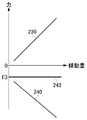
Next, an example in which the drive control unit 208 adjusts the control signal supplied from the driver IC 96 to the actuator 94 so that the assist force corresponding to the load information provided from the application is applied to the analog stick 24 will be described.

図11は、アナログスティック24の操作に対するアシスト力F3を生成する際に、アクチュエータ94により生成されるアクチュエータ生成力240を示す。駆動制御部208は、復帰ばね179によるばね復元力230と、アクチュエータ94によるアクチュエータ生成力240との合力が、アシスト力F3であるアシスト負荷242となるように、アクチュエータ94を制御する。   FIG. 11 shows the actuator generation force 240 generated by the actuator 94 when generating the assist force F3 for the operation of the analog stick 24. FIG. The drive control unit 208 controls the actuator 94 so that the resultant force of the spring restoring force 230 by the return spring 179 and the actuator generating force 240 by the actuator 94 becomes the assist load 242 that is the assist force F3.

このようにアナログスティック24が復帰ばね179により支持されており、アナログスティック24の傾動量に応じて、復帰ばね179から傾動方向に対する反発力が自動生成される場合には、駆動制御部208が、復帰ばね179により生成される反発力も加味して、アクチュエータ94による生成負荷を制御することが好ましい。そのため入力受付部204は、アナログスティック24の操作方向および操作量を受け付けると、駆動制御部208に対して、その操作方向および操作量を通知し、駆動制御部208が、操作量に応じたばね復元力を加味して、ドライバIC96からアクチュエータ94に供給する制御信号を調整する。これにより駆動制御部208は、アナログスティック24の傾動量に関わらず、一定の反発力ないしはアシスト力をアナログスティック24に対して付与することができ、ユーザは、ゲームにおいて設定したキャラクタや装備類の重量感、またゲーム状況に応じた重量感を、アナログスティック24を操作する指先で感じることが可能となる。   In this way, when the analog stick 24 is supported by the return spring 179, and the repulsive force in the tilt direction is automatically generated from the return spring 179 according to the tilt amount of the analog stick 24, the drive control unit 208 is It is preferable to control the load generated by the actuator 94 in consideration of the repulsive force generated by the return spring 179. Therefore, when receiving the operation direction and operation amount of the analog stick 24, the input reception unit 204 notifies the drive control unit 208 of the operation direction and operation amount, and the drive control unit 208 restores the spring according to the operation amount. In consideration of the force, the control signal supplied from the driver IC 96 to the actuator 94 is adjusted. As a result, the drive control unit 208 can apply a constant repulsive force or assist force to the analog stick 24 regardless of the tilt amount of the analog stick 24, and the user can determine the character or equipment set in the game. A feeling of weight and a feeling of weight according to the game situation can be felt with the fingertips operating the analog stick 24.

以上は、アナログスティック24が復帰ばね179により支持されている多方向操作入力装置100におけるアクチュエータ94の制御手法であるが、以下に示すように、アナログスティック24を復帰ばね179により支持せず、アナログスティック24の操作軸157の傾動を、4つのアクチュエータにより制御するようにしてもよい。   The above is the control method of the actuator 94 in the multidirectional operation input device 100 in which the analog stick 24 is supported by the return spring 179. As shown below, the analog stick 24 is not supported by the return spring 179, The tilt of the operation shaft 157 of the stick 24 may be controlled by four actuators.

図12は、ゲームシステム1の構成の別の例を示す。図6に示すゲームシステム1と比較すると、図12に示すゲームシステム1は、アナログスティック24に負荷を付与するために、4つのアクチュエータ94c〜94fを備え、アナログスティック24を中立位置に復帰させるための復帰ばね179を備えていない点で異なっている。   FIG. 12 shows another example of the configuration of the game system 1. Compared with the game system 1 shown in FIG. 6, the game system 1 shown in FIG. 12 includes four actuators 94 c to 94 f in order to apply a load to the analog stick 24 and return the analog stick 24 to the neutral position. Is different in that the return spring 179 is not provided.

第1連動部材151には、第1連動部材151の変位量(回転量)を検出するための第1回転検出部153aが連結されるとともに、第1連動部材151の動きに対して反発力またはアシスト力を付与する第1アクチュエータ94cおよび第2アクチュエータ94dが連結される。第1アクチュエータ94cおよび第2アクチュエータ94dは、たとえば第1連動部材151の両端部のそれぞれにギアを介して連結されるモータであってよく、第1連動部材151に回転力を印加する機能をもつ。   The first interlocking member 151 is connected to a first rotation detecting unit 153a for detecting a displacement amount (rotation amount) of the first interlocking member 151, and a repulsive force against the movement of the first interlocking member 151 or A first actuator 94c and a second actuator 94d that apply assist force are connected. The first actuator 94c and the second actuator 94d may be motors connected to both ends of the first interlocking member 151 via gears, for example, and have a function of applying a rotational force to the first interlocking member 151. .

第2連動部材162には、第2連動部材162の変位量(回転量)を検出するための第2回転検出部153bが連結されるとともに、第2連動部材162の動きに対して反発力またはアシスト力を付与する第3アクチュエータ94eおよび第4アクチュエータ94fが連結される。第3アクチュエータ94eおよび第4アクチュエータ94fは、たとえば第2連動部材162の両端部のそれぞれにギアを介して連結されるモータであってよく、第2連動部材162に回転力を印加する機能をもつ。   The second interlocking member 162 is connected to a second rotation detector 153b for detecting a displacement (rotation amount) of the second interlocking member 162, and a repulsive force against the movement of the second interlocking member 162 or A third actuator 94e and a fourth actuator 94f that apply assist force are connected. The third actuator 94e and the fourth actuator 94f may be, for example, motors connected to both ends of the second interlocking member 162 via gears, and have a function of applying a rotational force to the second interlocking member 162. .

なお図4に示す多方向操作入力装置100は、中立位置への復帰のために操作軸157が復帰ばね179で支持された復帰部材173上に支持された構成を有しているが、この例では、中立位置への復帰するための構成は、すべてアクチュエータ94c〜94fによって実現される。そのため4アクチュエータ構造を有する多方向操作入力装置においては、図4および図5に示す操作体158および、その下方の復帰部材173などの構成が省略され、構造を単純化することができる。   The multidirectional operation input device 100 shown in FIG. 4 has a configuration in which the operation shaft 157 is supported on a return member 173 supported by a return spring 179 for returning to the neutral position. Then, all the configurations for returning to the neutral position are realized by the actuators 94c to 94f. Therefore, in the multidirectional operation input device having a four-actuator structure, the configuration of the operation body 158 and the return member 173 below the operation body 158 shown in FIGS. 4 and 5 is omitted, and the structure can be simplified.

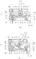
図13は、4アクチュエータ構造250の詳細を示す。第1連動部材151の両端部にはギア193c、193dが設けられ、第2連動部材162の両端部にはギア193e、193fが設けられる。第1アクチュエータ94cはモータ191cおよびギア192cを有し、ギア192cはギア193cにかみ合う。第2アクチュエータ94dはモータ191dおよびギア192dを有し、ギア192dはギア193dにかみ合う。第3アクチュエータ94eはモータ191eおよびギア192eを有し、ギア192eはギア193eにかみ合う。第4アクチュエータ94fはモータ191fおよびギア192fを有し、ギア192fはギア193fにかみ合う。   FIG. 13 shows details of the four-actuator structure 250. Gears 193c and 193d are provided at both ends of the first interlocking member 151, and gears 193e and 193f are provided at both ends of the second interlocking member 162. The first actuator 94c has a motor 191c and a gear 192c, and the gear 192c meshes with the gear 193c. The second actuator 94d has a motor 191d and a gear 192d, and the gear 192d meshes with the gear 193d. The third actuator 94e has a motor 191e and a gear 192e, and the gear 192e meshes with the gear 193e. The fourth actuator 94f has a motor 191f and a gear 192f, and the gear 192f meshes with the gear 193f.

操作軸157の姿勢を固定するためには、モータ191cおよびモータ191dは、互いに打ち消し合うトルクを生成し、またモータ191eおよびモータ191fも、互いに打ち消し合うトルクを生成すればよい。そこで駆動制御部208は、操作軸157にユーザからの操作力が加えられていない状態では、操作軸157が中立位置にくるように、モータ191c〜191fの制御信号を調整する。図4に示した多方向操作入力装置100のような中立位置復帰制御を行うためには、操作軸157が中立位置から傾動されると、中立位置に向かう方向に、復帰ばね179と同じような反発力を生成し、ユーザ操作から解放されれば、復帰ばね179の復元力と同様のトルクをモータ191c〜モータ191fに生成させる。このように4アクチュエータ構造250においては、駆動制御部208が、操作軸157の中立位置からのずれ量および傾動方向をもとに、モータ191c〜モータ191fにより中立位置に向かう方向に反発力を生成させることで、多方向操作入力装置100と同様の操作感をユーザに提供できる。   In order to fix the attitude of the operation shaft 157, the motor 191c and the motor 191d generate torques that cancel each other, and the motor 191e and the motor 191f also generate torques that cancel each other. Therefore, the drive control unit 208 adjusts the control signals of the motors 191c to 191f so that the operation shaft 157 is in the neutral position when the operation force from the user is not applied to the operation shaft 157. In order to perform neutral position return control like the multidirectional operation input device 100 shown in FIG. 4, when the operation shaft 157 is tilted from the neutral position, it is similar to the return spring 179 in the direction toward the neutral position. When the repulsive force is generated and released from the user operation, the motor 191c to the motor 191f generate the same torque as the restoring force of the return spring 179. As described above, in the four-actuator structure 250, the drive control unit 208 generates a repulsive force in the direction toward the neutral position by the motor 191c to the motor 191f based on the deviation amount from the neutral position and the tilt direction of the operation shaft 157. By doing so, it is possible to provide the user with the same operational feeling as the multidirectional operation input device 100.

なおアナログスティック24の頂部(回転操作子116)には、タッチセンサが設けられ、ユーザがアナログスティック24を操作しているか否かが検出されてもよい。駆動制御部208は、タッチセンサによりユーザがアナログスティック24をタッチしていないことを検出すると、中立位置復帰制御を実行するようにしてもよい。   Note that a touch sensor may be provided on the top of the analog stick 24 (the rotary operation element 116) to detect whether the user is operating the analog stick 24 or not. When the drive control unit 208 detects that the user does not touch the analog stick 24 by the touch sensor, the drive control unit 208 may execute neutral position return control.

4アクチュエータ構造250は、復帰ばね179を有しない構造であるため、駆動制御部208は、ばね力を加味する必要なく、ゲームアプリケーションから取得される負荷情報にしたがったアクチュエータ94c〜94fの制御を容易に行うことができる。図10(b)(c)に示す反発力F1、F2や、図11に示すアシスト力F3は、傾動量に関わらず一定の値であるため、駆動制御部208は、第1連動部材151の両端部に取り付けられたモータ191c、191dのトルク差、第2連動部材162の両端部に取り付けられたモータ191e、191fのトルク差を一定となるように調整することで、アナログスティック24(操作軸157)の操作に対して、一定の反発力ないしアシスト力を容易に付与することが可能となる。   Since the 4-actuator structure 250 is a structure that does not include the return spring 179, the drive control unit 208 can easily control the actuators 94c to 94f according to the load information acquired from the game application without having to consider the spring force. Can be done. Since the repulsive forces F1 and F2 shown in FIGS. 10B and 10C and the assist force F3 shown in FIG. 11 are constant values regardless of the tilting amount, the drive control unit 208 controls the first interlocking member 151. By adjusting the torque difference between the motors 191c and 191d attached to both ends and the torque difference between the motors 191e and 191f attached to both ends of the second interlocking member 162 to be constant, the analog stick 24 (operation shaft A certain repulsive force or assist force can be easily applied to the operation 157).

なおアナログスティック24には、左スティック24aと右スティック24bとが存在するが、それぞれの役割は異なるように設定されていることが多く、通常、左スティック24aは、キャラクタの操作に使用され、一方、右スティック24bは、ゲームにおける各種設定の際に使用される。そのため駆動制御部208は、左スティック24aと右スティック24bとで、アクチュエータ94から供給するトルクを異ならせてもよい。たとえば左スティック24aに対しては、アクチュエータ94に、負荷レベルに応じたトルクを生成させ、右スティック24bに対してはトルクを生成させない、ないしは負荷レベルに依存しないトルクを生成させるようにしてもよい。   The analog stick 24 has a left stick 24a and a right stick 24b, but their roles are often set differently. Usually, the left stick 24a is used for character operations. The right stick 24b is used for various settings in the game. Therefore, the drive control unit 208 may vary the torque supplied from the actuator 94 between the left stick 24a and the right stick 24b. For example, for the left stick 24a, the actuator 94 may generate torque according to the load level, and the right stick 24b may not generate torque or generate torque independent of the load level. .

アナログスティック24にアクチュエータ94を連結したことで、これまでにないアナログスティック24の操作感をゲームに取り入れることが可能となる。たとえば迷路ゲームにおいて、キャラクタの進行方向をアナログスティック24の傾き方向により決める場合に、正解ルート以外の道にはキャラクタが進みにくいように、アクチュエータ94が抵抗トルクを発生させる。これによりユーザがアナログスティック24を操作すると、重く傾けにくい方向は行き止まりになることを理解でき、正解ルートを早期に見つけやすくできる。たとえば迷路ゲームを、ビギナーモードで行う場合に、アナログスティック24に抵抗トルクを付与することで、初心者でも迷路ゲームを簡単に楽しめるようになる。また飛行機や電車などの乗り物の操縦シミュレータゲームにおいても、誤った方向には大きな抵抗トルクを印加することで、ユーザのアナログスティック24の操作を正しい方向にガイドすることも可能となる。   By connecting the actuator 94 to the analog stick 24, it becomes possible to incorporate an unprecedented sense of operation of the analog stick 24 into the game. For example, in a maze game, when the traveling direction of the character is determined by the tilt direction of the analog stick 24, the actuator 94 generates a resistance torque so that the character does not easily travel on a path other than the correct route. As a result, when the user operates the analog stick 24, it can be understood that the direction that is heavy and difficult to tilt becomes a dead end, and the correct route can be easily found at an early stage. For example, when a maze game is performed in the beginner mode, a resistance torque is applied to the analog stick 24 so that even a beginner can easily enjoy the maze game. Also, in a vehicle operation simulator game such as an airplane or a train, it is possible to guide the user's operation of the analog stick 24 in the correct direction by applying a large resistance torque in the wrong direction.

以上、駆動制御部208が、ゲームアプリケーションから提供される負荷レベルに基づいて、操作部70の操作方向に沿ってアクチュエータ94の発生トルクを制御する例を説明した。以下では、ゲームの状況に応じて、アクチュエータ94の発生トルクの方向を制御する例を説明する。   The example in which the drive control unit 208 controls the generated torque of the actuator 94 along the operation direction of the operation unit 70 has been described based on the load level provided from the game application. Hereinafter, an example in which the direction of the torque generated by the actuator 94 is controlled according to the game situation will be described.

図14(a)は、アナログスティック24の操作方向と、アクチュエータ94が生成する外力Fの方向を示す。これは、上記したように、アクチュエータ94が、アナログスティック24の操作方向に沿って外力Fをアナログスティック24に付与した場合の関係を示している。実施例で示したように、外力Fの大きさは、ユーザが選択したキャラクタや装備類などの属性情報により定められ、アナログスティック24の操作に対する重量感を変化させる。   FIG. 14A shows the operation direction of the analog stick 24 and the direction of the external force F generated by the actuator 94. This shows the relationship when the actuator 94 applies the external force F to the analog stick 24 along the operation direction of the analog stick 24 as described above. As shown in the embodiment, the magnitude of the external force F is determined by attribute information such as the character and equipment selected by the user, and changes the feeling of weight with respect to the operation of the analog stick 24.

図14(b)は、アナログスティック24の操作方向と、アクチュエータ94が生成する外力Tの方向を示す。ここで外力Fの大きさは、ユーザが選択したキャラクタや装備類に対応する負荷情報により定められ、外力Dの大きさおよび方向は、ゲーム状況に応じて設定される負荷情報により定められる。たとえばユーザがアナログスティック24を操作してゲーム中のプレイヤキャラクタを移動させている場合に、プレイヤキャラクタの進行方向に対して左から右に横風が吹いている場合、負荷情報取得部206は、ゲームアプリケーションから、ゲームの状況に対応する負荷情報を取得する。この負荷情報は、横風の強さに対応する負荷レベルを含み、さらに、プレイヤキャラクタの進行方向に対する角度情報も含む。ゲーム中において、風が一定方向に吹いているとすると、プレイヤキャラクタの進行方向に対する角度は、プレイヤキャラクタの進行方向に応じて変化する。そのためゲームアプリケーションは、プレイヤキャラクタの進行方向に変化があるたびに、またゲーム中での風の強さに変化があるたびに、負荷情報を生成して、負荷情報取得部206に提供する。これにより負荷情報取得部206は、時々刻々と変化するゲーム状況、つまりアナログスティック24に与える負荷に関する情報を適時取得することができる。   FIG. 14B shows the operation direction of the analog stick 24 and the direction of the external force T generated by the actuator 94. Here, the magnitude of the external force F is determined by load information corresponding to the character or equipment selected by the user, and the magnitude and direction of the external force D are determined by load information set according to the game situation. For example, when the user operates the analog stick 24 to move the player character in the game and the cross wind is blowing from the left to the right with respect to the traveling direction of the player character, the load information acquisition unit 206 Load information corresponding to the game situation is acquired from the application. This load information includes a load level corresponding to the strength of the cross wind, and further includes angle information with respect to the traveling direction of the player character. If the wind is blowing in a certain direction during the game, the angle of the player character with respect to the traveling direction changes according to the traveling direction of the player character. Therefore, the game application generates load information and provides it to the load information acquisition unit 206 every time there is a change in the traveling direction of the player character and every time there is a change in the strength of the wind in the game. Thereby, the load information acquisition unit 206 can acquire timely information on the game situation that changes from moment to moment, that is, the load applied to the analog stick 24.

駆動制御部208は、外力Fの負荷レベルおよび外力Dの負荷レベルをもとに、外力Fと外力Dを合成した合力Tの方向および負荷レベルを求める。外力Tの方向が、アナログスティック24の操作方向に沿っていなければ、合力Tの方向は、操作方向に対して角度をもつことになる。駆動制御部208は、アクチュエータ94を制御して、アナログスティック24に合力Tを付与させる。   Based on the load level of external force F and the load level of external force D, drive control unit 208 obtains the direction and load level of resultant force T obtained by combining external force F and external force D. If the direction of the external force T does not follow the operation direction of the analog stick 24, the direction of the resultant force T has an angle with respect to the operation direction. The drive control unit 208 controls the actuator 94 to apply the resultant force T to the analog stick 24.

既述したように、外力Dは、ゲーム状況により、アナログスティック24の操作とは無関係にアナログスティック24に付与される。そのためユーザがアナログスティック24を操作しなければ、アナログスティック24は外力Dにより右方向に傾動され、ゲーム中のプレイヤキャラクタは、右に移動することになる。これによりプレイヤキャラクタは、横風に吹かれて、右方向に動かされる挙動を示すことになる。   As described above, the external force D is applied to the analog stick 24 regardless of the operation of the analog stick 24 depending on the game situation. Therefore, if the user does not operate the analog stick 24, the analog stick 24 is tilted to the right by the external force D, and the player character in the game moves to the right. As a result, the player character is shown to behave in the right direction by being blown by a crosswind.

なお復帰ばね179を有する多方向操作入力装置100においては、アナログスティック24が傾動されると、復帰ばね179が復元力を生成し、復元力が外力Dと釣り合った位置でアナログスティック24の傾動が停止する。一方で、復帰ばね179を有しない4アクチュエータ構造250を有する操作入力装置においては自動で復元力が生成されないため、駆動制御部208は、外力Dの大きさに基づいて、アナログスティック24の傾動量を制御することが好ましい。具体的に駆動制御部208は、アナログスティック24に設けたタッチセンサによりアナログスティック24が操作されていないことが検出されると、中立位置復帰制御を実行して、アナログスティック24の復帰力が外力Dと釣り合った位置でアナログスティック24の傾動が停止するようにされることが好ましい。   In the multidirectional operation input device 100 having the return spring 179, when the analog stick 24 is tilted, the return spring 179 generates a restoring force, and the analog stick 24 is tilted at a position where the restoring force is balanced with the external force D. Stop. On the other hand, since the restoring force is not automatically generated in the operation input device having the four-actuator structure 250 that does not have the return spring 179, the drive control unit 208 determines the amount of tilt of the analog stick 24 based on the magnitude of the external force D. Is preferably controlled. Specifically, when it is detected by the touch sensor provided on the analog stick 24 that the analog stick 24 is not operated, the drive control unit 208 executes neutral position return control, and the return force of the analog stick 24 is an external force. The tilt of the analog stick 24 is preferably stopped at a position balanced with D.

以下では、駆動制御部208が、設定された負荷レベルに基づいて、アクチュエータ94の発生トルクを制御する例について説明する。
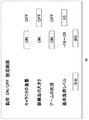
図15は、表示装置20に表示される負荷設定画面を示す。この負荷設定画面は、たとえばゲーム開始前に表示される。なお負荷設定画面で選択した項目は、全てのゲームに対して有効とされてもよく、また、そのゲーム限りにおいて有効とされてもよい。
Hereinafter, an example in which the drive control unit 208 controls the torque generated by the actuator 94 based on the set load level will be described.
FIG. 15 shows a load setting screen displayed on the display device 20. This load setting screen is displayed, for example, before the game starts. The item selected on the load setting screen may be valid for all games, or may be valid only for that game.

ユーザは方向キー23などを操作して、アナログスティック24にトルクを印加するためのパラメータを選択する。この例では、「キャラクタの重量」、「装備品の大きさ」、「ゲームの状況」のパラメータが用意され、パラメータをONに設定すると、そのパラメータに関する負荷情報にしたがってアクチュエータ94が駆動されるようになる。   The user operates a direction key 23 or the like to select a parameter for applying torque to the analog stick 24. In this example, parameters of “character weight”, “equipment size”, and “game situation” are prepared, and when the parameter is set to ON, the actuator 94 is driven according to load information regarding the parameter. become.

「基準負荷レベル」の項目は、アナログスティック24に印加するバイアストルクを設定するために用意される。バイアストルクは、パラメータに関する負荷情報とは無関係にアナログスティック24に印加されるトルクであり、パラメータに関する負荷情報がゲームアプリケーションから供給されると、アナログスティック24に印加されるトルクは、バイアストルクから加算または減算することで定められる。図15に示す例では、基準負荷レベルが10に設定されているが、これは、上記パラメータに関する負荷情報がゲームアプリケーションから供給されない状態では、アクチュエータ94が、アナログスティック24に対して、負荷レベル10に対応するバイアストルクを常時印加する。基準負荷レベルが0に設定されると、バイアストルクは印加されない。   The item “reference load level” is prepared for setting a bias torque to be applied to the analog stick 24. The bias torque is a torque applied to the analog stick 24 regardless of the load information related to the parameter. When the load information related to the parameter is supplied from the game application, the torque applied to the analog stick 24 is added from the bias torque. Or it is determined by subtraction. In the example shown in FIG. 15, the reference load level is set to 10. This is because the actuator 94 has a load level of 10 with respect to the analog stick 24 in a state where the load information regarding the parameters is not supplied from the game application. A bias torque corresponding to is always applied. When the reference load level is set to 0, no bias torque is applied.

ユーザが各パラメータのONまたはOFF、および基準負荷レベル値を設定すると、保持部210が、この設定情報を保持する。駆動制御部208は、この設定情報を参照して、アクチュエータ94を制御する。たとえば「装備品の大きさ」に関して、負荷OFFが設定されていれば、負荷情報取得部206が、ゲームアプリケーションから、選択された装備品に対応する負荷情報を取得しても、駆動制御部208は、その負荷情報によってアクチュエータ94の動作状態を変更しない。一方、「ゲームの状況」に関して、負荷ONが設定されていれば、負荷情報取得部206が、ゲームアプリケーションから、ゲームの状況に対応する負荷情報を取得すると、駆動制御部208は、その負荷情報によってアクチュエータ94の動作状態を変更する。このようにユーザが、アクチュエータ94によるトルク生成の要因となるパラメータを設定することで、アクチュエータ94がユーザの好みに応じた負荷をアナログスティック24に付与することが可能となる。   When the user sets each parameter ON or OFF and the reference load level value, the holding unit 210 holds this setting information. The drive control unit 208 controls the actuator 94 with reference to this setting information. For example, if the load OFF is set for the “equipment size”, even if the load information acquisition unit 206 acquires load information corresponding to the selected equipment from the game application, the drive control unit 208 Does not change the operating state of the actuator 94 according to the load information. On the other hand, if the load ON is set for the “game status”, when the load information acquisition unit 206 acquires the load information corresponding to the game status from the game application, the drive control unit 208 displays the load information. To change the operating state of the actuator 94. As described above, the user sets a parameter that causes torque generation by the actuator 94, so that the actuator 94 can apply a load according to the user's preference to the analog stick 24.

このように保持部210は、ユーザにより予め登録された基準負荷レベルを、基準負荷情報として保持し、また負荷調整に使用するパラメータ情報も保持する。負荷情報取得部206は、保持部210から基準負荷情報を取得し、駆動制御部208は、取得した基準負荷情報にしたがってアクチュエータ94を制御する。   Thus, the holding unit 210 holds the reference load level registered in advance by the user as the reference load information, and also holds parameter information used for load adjustment. The load information acquisition unit 206 acquires reference load information from the holding unit 210, and the drive control unit 208 controls the actuator 94 according to the acquired reference load information.

通常、抵抗となるバイアストルクが大きければ、アナログスティック24の操作感は重くなるため、キャラクタに俊敏な動きを行わせることが難しくなる。そのためユーザ同士で対戦する場合には、上級ユーザのバイアストルクを大きく設定し、一方で、初級ユーザのバイアストルクを0に設定することで、ハンデ戦を実現することも可能となる。また、上記の例は、ユーザが、自分用にパラメータ情報および基準負荷情報を設定することを示したが、たとえばゲーム大会のレギュレーションとして、各種の設定情報が定められるようにしてもよい。これにより全ユーザの操作条件を統一することができるため、公平な大会を開催することも可能となる。   Normally, if the bias torque serving as resistance is large, the operation feeling of the analog stick 24 becomes heavy, and it becomes difficult to make the character perform agile movement. Therefore, in the case of a battle between users, it is possible to realize a handicap battle by setting the bias torque of the advanced user large, while setting the bias torque of the beginner user to 0. Further, the above example shows that the user sets the parameter information and the reference load information for himself, but various setting information may be defined as, for example, regulation of the game tournament. As a result, the operating conditions of all users can be unified, and a fair competition can be held.

なおユーザは、複数の基準負荷レベルを、保持部210に保持させてもよい。たとえば表示装置20に、複数の基準負荷レベルを設定するための画面が表示され、ユーザが、複数の基準負荷レベルを保持部210に登録できるようにしてもよい。ゲーム中、ユーザは、所定のボタン、たとえばRボタン26bを操作して、バイアストルクを変更できる。たとえば、ゲームにおいて、銃の照準をアナログスティック24で合わせる場合には、抵抗トルクを大きくして、アナログスティック24をゆっくり操作できるようにし、一方、キャラクタをアナログスティック24で移動させる場合には、抵抗トルクを小さくして、アナログスティック24を軽く操作できることが好ましい。   The user may cause the holding unit 210 to hold a plurality of reference load levels. For example, a screen for setting a plurality of reference load levels may be displayed on the display device 20 so that the user can register a plurality of reference load levels in the holding unit 210. During the game, the user can change the bias torque by operating a predetermined button, for example, the R button 26b. For example, in a game, when the gun is aimed with the analog stick 24, the resistance torque is increased so that the analog stick 24 can be operated slowly, while when the character is moved with the analog stick 24, the resistance is increased. It is preferable that the analog stick 24 can be operated lightly by reducing the torque.

入力受付部204は、ユーザからのバイアストルクの切替入力、すなわち所定のボタン操作を受け付ける。入力受付部204が切替入力を受け付けると、負荷情報取得部206が、現在使用している負荷情報とは異なる別の負荷情報を保持部210から取得し、駆動制御部208が、別の負荷情報にしたがってアクチュエータ94を制御する。このように簡単な操作でバイアストルクを切り替え可能とすることで、バイアストルクの切り替え操作そのものを、ゲーム性に組み入れることも可能となり、新たなゲームの楽しみ方をユーザに提供することが可能となる。   The input receiving unit 204 receives a bias torque switching input from the user, that is, a predetermined button operation. When the input reception unit 204 receives the switching input, the load information acquisition unit 206 acquires different load information different from the currently used load information from the holding unit 210, and the drive control unit 208 acquires the different load information. The actuator 94 is controlled accordingly. By making it possible to switch the bias torque with such a simple operation, it is possible to incorporate the switching operation of the bias torque itself into the game characteristics, and to provide the user with a new way to enjoy the game. .

以上、本発明を実施例をもとに説明した。この実施例は例示であり、それらの各構成要素や各処理プロセスの組み合わせにいろいろな変形例が可能なこと、またそうした変形例も本発明の範囲にあることは当業者に理解されるところである。実施例では、操作部と処理部とが一体型のゲームシステムについて説明したが、操作部と処理部とが別体となっていても構わない。また実施例では、操作部70の操作方向に沿った負荷を生成することを説明したが、アクチュエータ94は、操作方向とは異なる方向に負荷を生成してもよい。   In the above, this invention was demonstrated based on the Example. This embodiment is an exemplification, and it will be understood by those skilled in the art that various modifications can be made to the combination of each component and each processing process, and such modifications are also within the scope of the present invention. . In the embodiment, a game system in which the operation unit and the processing unit are integrated has been described. However, the operation unit and the processing unit may be separated. In the embodiment, the generation of the load along the operation direction of the operation unit 70 has been described. However, the actuator 94 may generate the load in a direction different from the operation direction.

実施例においては、駆動制御部208が、アクチュエータ94を制御して、アナログスティック24の操作に対して負荷を付与させることを説明した。駆動制御部208は、ゲームアプリケーションから、アナログスティック24の操作が、選択した少なくとも1つのオブジェクト(たとえばプレイヤキャラクタ)を動かすためのものであるか否かを示す情報を受け取ってもよい。この情報が、アナログスティック24の操作がプレイヤキャラクタを動かすものであることを示す場合に、駆動制御部208は、アクチュエータ94によりアナログスティック24の操作に対して負荷を付与させるようにしてもよい。つまり駆動制御部208は、ユーザがアナログスティック24を操作してプレイヤキャラクタを動かす際に、アクチュエータ94によりアナログスティック24の操作に対して負荷を付与させるようにしてもよい。これにより駆動制御部208は、ゲーム中でのゲームキャラクタの操作時において、アナログスティック24の操作感を調整することが可能となる。   In the embodiment, it has been described that the drive control unit 208 controls the actuator 94 to apply a load to the operation of the analog stick 24. The drive control unit 208 may receive information indicating whether or not the operation of the analog stick 24 is for moving at least one selected object (for example, a player character) from the game application. If this information indicates that the operation of the analog stick 24 moves the player character, the drive control unit 208 may apply a load to the operation of the analog stick 24 by the actuator 94. That is, the drive control unit 208 may apply a load to the operation of the analog stick 24 by the actuator 94 when the user operates the analog stick 24 to move the player character. As a result, the drive control unit 208 can adjust the operational feeling of the analog stick 24 when the game character is operated during the game.

1…ゲームシステム、10…ゲーム装置、60…CPU、70…操作部、94…アクチュエータ、94a…第1アクチュエータ、94b…第2アクチュエータ、96…ドライバIC、100…多方向操作入力装置、200…処理部、202…ゲーム実行部、204…入力受付部、206…負荷情報取得部、208…駆動制御部、210…保持部。 DESCRIPTION OF SYMBOLS 1 ... Game system, 10 ... Game device, 60 ... CPU, 70 ... Operation part, 94 ... Actuator, 94a ... 1st actuator, 94b ... 2nd actuator, 96 ... Driver IC, 100 ... Multidirectional operation input device, 200 ... Processing unit 202... Game execution unit 204... Input reception unit 206. Load information acquisition unit 208. Drive control unit 210.

Claims (20)

ゲームシステムであって、
ユーザが操作する操作部と、
操作部に負荷を付与するアクチュエータと、
アクチュエータを制御する制御部と、
ゲームアプリケーションから、ユーザにより選択されたオブジェクトに対応する負荷情報を取得する取得部と、を備え、
前記制御部は、前記取得部が取得した負荷情報にしたがって、前記アクチュエータを制御することを特徴とするゲームシステム。
A game system,
An operation unit operated by a user;
An actuator for applying a load to the operation unit;
A control unit for controlling the actuator;
An acquisition unit that acquires load information corresponding to the object selected by the user from the game application,
The said control part controls the said actuator according to the load information which the said acquisition part acquired, The game system characterized by the above-mentioned.
前記取得部は、ユーザにより選択された複数のオブジェクトに対応する負荷情報を取得し、
前記制御部は、前記取得部が取得した負荷情報にしたがって、前記アクチュエータを制御することを特徴とする請求項1に記載のゲームシステム。
The acquisition unit acquires load information corresponding to a plurality of objects selected by a user,
The game system according to claim 1, wherein the control unit controls the actuator according to load information acquired by the acquisition unit.
前記取得部は、ユーザにより選択された複数のオブジェクトのそれぞれに対応する複数の負荷情報を取得し、
前記制御部は、前記取得部が取得した複数の負荷情報にしたがって、前記アクチュエータを制御することを特徴とする請求項1または2に記載のゲームシステム。
The acquisition unit acquires a plurality of load information corresponding to each of a plurality of objects selected by a user,
The game system according to claim 1, wherein the control unit controls the actuator in accordance with a plurality of pieces of load information acquired by the acquisition unit.
前記操作部の操作を受け付ける受付部をさらに備え、
前記制御部は、前記アクチュエータを制御して、前記受付部が受け付けた前記操作部の操作に対して負荷を付与させることを特徴とする請求項1から3のいずれかに記載のゲームシステム。
A reception unit that receives an operation of the operation unit;
The game system according to claim 1, wherein the control unit controls the actuator to apply a load to the operation of the operation unit received by the reception unit.
前記制御部は、ユーザが前記操作部を操作して少なくとも1つのオブジェクトを動かす際に、前記アクチュエータにより前記操作部の操作に対して負荷を付与させることを特徴とする請求項4に記載のゲームシステム。   The game according to claim 4, wherein when the user operates the operation unit to move at least one object, the control unit applies a load to the operation of the operation unit by the actuator. system. 前記アクチュエータは、前記操作部の操作方向に沿って負荷を付与することを特徴とする請求項4または5に記載のゲームシステム。   The game system according to claim 4, wherein the actuator applies a load along an operation direction of the operation unit. 前記取得部は、ゲームアプリケーションから、ゲームの状況に対応する負荷情報を取得し、
前記制御部は、前記取得部が取得した負荷情報にしたがって、前記アクチュエータを制御することを特徴とする請求項2または3に記載のゲームシステム。
The acquisition unit acquires load information corresponding to a game situation from a game application,
The game system according to claim 2, wherein the control unit controls the actuator according to the load information acquired by the acquisition unit.
前記制御部は、ゲームの状況に対応する負荷情報にしたがって、前記操作部の操作に関係なく前記アクチュエータを制御して、前記操作部に負荷を付与させることを特徴とする請求項7に記載のゲームシステム。   The said control part controls the said actuator irrespective of operation of the said operation part according to the load information corresponding to the condition of a game, The load is given to the said operation part, It is characterized by the above-mentioned. Game system. 前記制御部は、前記アクチュエータを、基準負荷情報にしたがって制御しており、前記取得部が負荷情報を取得すると、基準負荷情報と、取得した負荷情報をもとに、前記アクチュエータを制御することを特徴とする請求項1から8のいずれかに記載のゲームシステム。   The control unit controls the actuator according to reference load information, and when the acquisition unit acquires the load information, the control unit controls the actuator based on the reference load information and the acquired load information. The game system according to claim 1, wherein the game system is characterized in that 前記制御部は、前記アクチュエータに、ユーザによる操作部の操作をアシストする負荷を生成させることを特徴とする請求項1から9のいずれかに記載のゲームシステム。   The game system according to claim 1, wherein the control unit causes the actuator to generate a load that assists a user to operate the operation unit. ゲームシステムであって、
ユーザが操作する操作部と、
操作部に負荷を付与するアクチュエータと、
アクチュエータを制御する制御部と、
負荷情報を保持する保持部と、
前記保持部から負荷情報を取得する取得部と、
前記操作部の操作を受け付ける受付部と、を備え、
前記制御部は、前記取得部が取得した負荷情報にしたがって前記アクチュエータを制御して、前記受付部が受け付けた前記操作部の操作に対して負荷を付与させることを特徴とするゲームシステム。
A game system,
An operation unit operated by a user;
An actuator for applying a load to the operation unit;
A control unit for controlling the actuator;
A holding unit for holding load information;
An acquisition unit for acquiring load information from the holding unit;
A reception unit that receives an operation of the operation unit,
The said control part controls the said actuator according to the load information which the said acquisition part acquired, and gives a load with respect to operation of the said operation part which the said reception part received.
前記保持部は、登録された複数の負荷情報を保持しており、
前記受付部がユーザからの切替入力を受け付けると、前記取得部が、前記保持部から別の負荷情報を取得し、前記制御部が、前記取得部が取得した別の負荷情報にしたがって、前記アクチュエータを制御することを特徴とする請求項11に記載のゲームシステム。
The holding unit holds a plurality of registered load information,
When the receiving unit receives a switching input from a user, the acquiring unit acquires another load information from the holding unit, and the control unit is configured to acquire the actuator according to the other load information acquired by the acquiring unit. The game system according to claim 11, wherein the game system is controlled.
前記制御部は、ゲームにおいてユーザが前記操作部を操作してオブジェクトを動かす際に、前記アクチュエータにより前記操作部の操作に対して負荷を付与させることを特徴とする請求項11または12に記載のゲームシステム。   13. The control unit according to claim 11, wherein when the user moves the object by operating the operation unit in a game, the control unit applies a load to the operation of the operation unit by the actuator. Game system. 前記アクチュエータは、前記操作部の操作方向に沿って負荷を付与することを特徴とする請求項11から13のいずれかに記載のゲームシステム。   The game system according to claim 11, wherein the actuator applies a load along an operation direction of the operation unit. コンピュータに、
操作部の操作の検出情報を取得する機能と、
ゲームアプリケーションから、ユーザにより選択されたオブジェクトに対応する負荷情報を取得する機能と、
取得した負荷情報にしたがって、操作部に負荷を付与するアクチュエータを制御する機能と、を実現させるためのプログラムであって、
制御機能は、アクチュエータを制御して、操作部の操作に対して負荷を付与する機能を含む、ことを特徴とするプログラム。
On the computer,
A function for obtaining detection information of operation of the operation unit;
A function of acquiring load information corresponding to the object selected by the user from the game application;
A function for controlling an actuator that applies a load to the operation unit according to the acquired load information,
The control function includes a function of controlling the actuator and applying a load to the operation of the operation unit.
負荷情報の取得機能が、複数の負荷情報を取得した場合に、制御機能は、複数の負荷情報にしたがってアクチュエータを制御する機能を含む、
ことを特徴とする請求項15に記載のプログラム。
When the load information acquisition function acquires a plurality of load information, the control function includes a function of controlling the actuator according to the plurality of load information.
The program according to claim 15.
制御機能は、ゲームにおいてユーザが操作部を操作して、少なくとも1つのオブジェクトを動かす際に、アクチュエータにより操作部の操作に対して負荷を付与させることを特徴とする請求項15または16に記載のプログラム。   The control function according to claim 15 or 16, wherein a load is applied to an operation of the operation unit by an actuator when the user operates the operation unit and moves at least one object in the game. program. 制御機能は、アクチュエータにより操作部の操作方向に沿って負荷を付与させることを特徴とする請求項16または17に記載のプログラム。   The program according to claim 16 or 17, wherein the control function applies a load along an operation direction of the operation unit by an actuator. コンピュータに、
複数の負荷情報を保持する保持部から、負荷情報を取得する機能と、
取得した負荷情報にしたがって、操作部に負荷を付与するアクチュエータを制御する機能と、
ユーザからの切替入力を受け付ける機能と、を実現させるためのプログラムであって、
受付機能が切替入力を受け付けると、取得機能が保持部から別の負荷情報を取得し、制御機能が、別の負荷情報にしたがってアクチュエータを制御する機能を含む、
ことを特徴とするプログラム。
On the computer,
A function of acquiring load information from a holding unit that holds a plurality of load information;
A function for controlling an actuator that applies a load to the operation unit according to the acquired load information;
A program for realizing a function of accepting a switching input from a user,
When the reception function receives the switching input, the acquisition function acquires another load information from the holding unit, and the control function includes a function of controlling the actuator according to the other load information.
A program characterized by that.
請求項15から19のいずれかに記載のプログラムを記録したコンピュータ読取可能な記録媒体。   A computer-readable recording medium on which the program according to claim 15 is recorded.
JP2014129599A 2014-06-24 2014-06-24 Game system Pending JP2016007345A (en)

Priority Applications (2)

Application Number Priority Date Filing Date Title
JP2014129599A JP2016007345A (en) 2014-06-24 2014-06-24 Game system
PCT/JP2015/055414 WO2015198634A1 (en) 2014-06-24 2015-02-25 Game system

Applications Claiming Priority (1)

Application Number Priority Date Filing Date Title
JP2014129599A JP2016007345A (en) 2014-06-24 2014-06-24 Game system

Publications (2)

Publication Number Publication Date
JP2016007345A true JP2016007345A (en) 2016-01-18
JP2016007345A5 JP2016007345A5 (en) 2017-08-31

Family

ID=54937737

Family Applications (1)

Application Number Title Priority Date Filing Date
JP2014129599A Pending JP2016007345A (en) 2014-06-24 2014-06-24 Game system

Country Status (2)

Country Link
JP (1) JP2016007345A (en)
WO (1) WO2015198634A1 (en)

Cited By (7)

* Cited by examiner, † Cited by third party
Publication number Priority date Publication date Assignee Title
JPWO2021038935A1 (en) * 2019-08-28 2021-03-04
WO2021038934A1 (en) * 2019-08-28 2021-03-04 アルプスアルパイン株式会社 Operation device
JP2021049200A (en) * 2019-09-25 2021-04-01 株式会社コナミアミューズメント Game system, control method thereof and computer program
WO2022107259A1 (en) * 2020-11-18 2022-05-27 任天堂株式会社 Information processing system, controller, information processing method, and information processing program
WO2022123737A1 (en) * 2020-12-10 2022-06-16 任天堂株式会社 Information processing system, controller, information processing method, and information processing program
WO2022130596A1 (en) * 2020-12-17 2022-06-23 任天堂株式会社 Input device, game controller, and information processing device
WO2023233624A1 (en) * 2022-06-02 2023-12-07 株式会社ソニー・インタラクティブエンタテインメント Information processing apparatus for driving operation member

Families Citing this family (1)

* Cited by examiner, † Cited by third party
Publication number Priority date Publication date Assignee Title
CN111346368A (en) * 2020-02-28 2020-06-30 歌尔科技有限公司 Game paddle and rocker feedback force device thereof

Citations (9)

* Cited by examiner, † Cited by third party
Publication number Priority date Publication date Assignee Title
JPH04232829A (en) * 1990-12-28 1992-08-21 Namco Ltd Steering reaction force generating device for driving simulator
JPH09502555A (en) * 1994-05-19 1997-03-11 エクソス,インコーポレイテッド Interactive simulation system with force feedback input device
JPH11161423A (en) * 1997-11-28 1999-06-18 Mitsumi Electric Co Ltd Safety device for joy stick provided with force feedback function
JP2000056668A (en) * 1998-08-06 2000-02-25 Koyo Seiko Co Ltd Driving simulator
JP2005300914A (en) * 2004-04-12 2005-10-27 Nissan Diesel Motor Co Ltd Steering reaction force generating device for vehicle drive simulation device
JP2007111190A (en) * 2005-10-19 2007-05-10 Taito Corp Game device, and game server device
JP2008113787A (en) * 2006-11-02 2008-05-22 Taito Corp Game device for displaying brake point reduced map
JP2012090720A (en) * 2010-10-26 2012-05-17 Konami Digital Entertainment Co Ltd Game system
JP2013505470A (en) * 2009-09-17 2013-02-14 セントレ・ナショナル・デ・ラ・レシェルシェ・サイエンティフィーク Method for simulating specific movement by tactile feedback and apparatus for executing the method

Patent Citations (9)

* Cited by examiner, † Cited by third party
Publication number Priority date Publication date Assignee Title
JPH04232829A (en) * 1990-12-28 1992-08-21 Namco Ltd Steering reaction force generating device for driving simulator
JPH09502555A (en) * 1994-05-19 1997-03-11 エクソス,インコーポレイテッド Interactive simulation system with force feedback input device
JPH11161423A (en) * 1997-11-28 1999-06-18 Mitsumi Electric Co Ltd Safety device for joy stick provided with force feedback function
JP2000056668A (en) * 1998-08-06 2000-02-25 Koyo Seiko Co Ltd Driving simulator
JP2005300914A (en) * 2004-04-12 2005-10-27 Nissan Diesel Motor Co Ltd Steering reaction force generating device for vehicle drive simulation device
JP2007111190A (en) * 2005-10-19 2007-05-10 Taito Corp Game device, and game server device
JP2008113787A (en) * 2006-11-02 2008-05-22 Taito Corp Game device for displaying brake point reduced map
JP2013505470A (en) * 2009-09-17 2013-02-14 セントレ・ナショナル・デ・ラ・レシェルシェ・サイエンティフィーク Method for simulating specific movement by tactile feedback and apparatus for executing the method
JP2012090720A (en) * 2010-10-26 2012-05-17 Konami Digital Entertainment Co Ltd Game system

Non-Patent Citations (2)

* Cited by examiner, † Cited by third party
Title
"PSPゲームレビュー「エースコンバット X2 ジョイントアサルト」", GAME WATCH[ONLINE], JPN6019003792, 6 September 2010 (2010-09-06), ISSN: 0004110039 *
"グランツーリスモ4", 電撃PLAYSTATION VOL.303, vol. 第11巻 第11号 通巻299号, JPN6018024194, 25 March 2005 (2005-03-25), pages 94 - 95, ISSN: 0004110040 *

Cited By (11)

* Cited by examiner, † Cited by third party
Publication number Priority date Publication date Assignee Title
JPWO2021038935A1 (en) * 2019-08-28 2021-03-04
WO2021038935A1 (en) * 2019-08-28 2021-03-04 アルプスアルパイン株式会社 Operation device
WO2021038934A1 (en) * 2019-08-28 2021-03-04 アルプスアルパイン株式会社 Operation device
CN114008557A (en) * 2019-08-28 2022-02-01 阿尔卑斯阿尔派株式会社 Operating device
JP7297072B2 (en) 2019-08-28 2023-06-23 アルプスアルパイン株式会社 Operating device
JP2021049200A (en) * 2019-09-25 2021-04-01 株式会社コナミアミューズメント Game system, control method thereof and computer program
WO2021059878A1 (en) * 2019-09-25 2021-04-01 株式会社コナミアミューズメント Game system, method of controlling same, and computer program
WO2022107259A1 (en) * 2020-11-18 2022-05-27 任天堂株式会社 Information processing system, controller, information processing method, and information processing program
WO2022123737A1 (en) * 2020-12-10 2022-06-16 任天堂株式会社 Information processing system, controller, information processing method, and information processing program
WO2022130596A1 (en) * 2020-12-17 2022-06-23 任天堂株式会社 Input device, game controller, and information processing device
WO2023233624A1 (en) * 2022-06-02 2023-12-07 株式会社ソニー・インタラクティブエンタテインメント Information processing apparatus for driving operation member

Also Published As

Publication number Publication date
WO2015198634A1 (en) 2015-12-30

Similar Documents

Publication Publication Date Title
WO2015198634A1 (en) Game system
JP3847058B2 (en) GAME SYSTEM AND GAME INFORMATION STORAGE MEDIUM USED FOR THE SAME
EP2497551B1 (en) Information processing program, information processing apparatus, information processing system, and information processing method
US7495665B2 (en) Storage medium having game program stored thereon and game apparatus
JP2007130312A (en) Game program and game apparatus
JP6581341B2 (en) Information processing apparatus, information processing program, information processing method, and information processing system
JP4667755B2 (en) GAME DEVICE AND GAME PROGRAM
CN111831104A (en) Head-mounted display system, related method and related computer readable recording medium
JP3819416B2 (en) GAME SYSTEM AND GAME INFORMATION STORAGE MEDIUM USED FOR THE SAME
JP4669504B2 (en) GAME SYSTEM AND GAME INFORMATION STORAGE MEDIUM USED FOR THE SAME
JP5718992B2 (en) Driving simulation apparatus and driving simulation program using portable terminal
JP2003225467A (en) Game machine and game program
JP7248720B2 (en) GAME PROGRAM, GAME DEVICE, GAME SYSTEM, AND GAME PROCESSING METHOD
JP3847327B2 (en) GAME SYSTEM AND GAME INFORMATION STORAGE MEDIUM USED FOR THE SAME
JP7373147B2 (en) game system
JP4624398B2 (en) GAME SYSTEM AND GAME INFORMATION STORAGE MEDIUM USED FOR THE SAME
JP4456590B2 (en) GAME SYSTEM AND GAME INFORMATION STORAGE MEDIUM USED FOR THE SAME
US20230277936A1 (en) Information processing system, non-transitory computer-readable storage medium having stored therein information processing program, information processing method, and information processing apparatus
WO2018101890A1 (en) Electronic input device
JP4271225B2 (en) GAME SYSTEM AND GAME INFORMATION STORAGE MEDIUM USED FOR THE SAME
JP3889032B2 (en) GAME SYSTEM AND GAME INFORMATION STORAGE MEDIUM USED FOR THE SAME
JP6246991B2 (en) Information processing program, information processing apparatus, information processing system, and information processing method
JP4394098B2 (en) GAME SYSTEM AND GAME INFORMATION STORAGE MEDIUM USED FOR THE SAME
JP4160084B2 (en) GAME SYSTEM AND GAME INFORMATION STORAGE MEDIUM USED FOR THE SAME
JP4656659B2 (en) GAME SYSTEM AND GAME INFORMATION STORAGE MEDIUM USED FOR THE SAME

Legal Events

Date Code Title Description
A621 Written request for application examination

Free format text: JAPANESE INTERMEDIATE CODE: A621

Effective date: 20170623

A521 Request for written amendment filed

Free format text: JAPANESE INTERMEDIATE CODE: A523

Effective date: 20170724

A131 Notification of reasons for refusal

Free format text: JAPANESE INTERMEDIATE CODE: A131

Effective date: 20180703

A521 Request for written amendment filed

Free format text: JAPANESE INTERMEDIATE CODE: A523

Effective date: 20180831

A131 Notification of reasons for refusal

Free format text: JAPANESE INTERMEDIATE CODE: A131

Effective date: 20190212

A521 Request for written amendment filed

Free format text: JAPANESE INTERMEDIATE CODE: A523

Effective date: 20190412

A02 Decision of refusal

Free format text: JAPANESE INTERMEDIATE CODE: A02

Effective date: 20190910