JP2016006471A - Image forming apparatus - Google Patents
Image forming apparatus Download PDFInfo
- Publication number
- JP2016006471A JP2016006471A JP2014151327A JP2014151327A JP2016006471A JP 2016006471 A JP2016006471 A JP 2016006471A JP 2014151327 A JP2014151327 A JP 2014151327A JP 2014151327 A JP2014151327 A JP 2014151327A JP 2016006471 A JP2016006471 A JP 2016006471A
- Authority
- JP
- Japan
- Prior art keywords
- bias
- transfer
- time
- image forming
- forming apparatus
- Prior art date
- Legal status (The legal status is an assumption and is not a legal conclusion. Google has not performed a legal analysis and makes no representation as to the accuracy of the status listed.)
- Pending
Links
Images


Classifications
-
- G—PHYSICS
- G03—PHOTOGRAPHY; CINEMATOGRAPHY; ANALOGOUS TECHNIQUES USING WAVES OTHER THAN OPTICAL WAVES; ELECTROGRAPHY; HOLOGRAPHY
- G03G—ELECTROGRAPHY; ELECTROPHOTOGRAPHY; MAGNETOGRAPHY
- G03G15/00—Apparatus for electrographic processes using a charge pattern
- G03G15/14—Apparatus for electrographic processes using a charge pattern for transferring a pattern to a second base
- G03G15/16—Apparatus for electrographic processes using a charge pattern for transferring a pattern to a second base of a toner pattern, e.g. a powder pattern, e.g. magnetic transfer
- G03G15/1665—Apparatus for electrographic processes using a charge pattern for transferring a pattern to a second base of a toner pattern, e.g. a powder pattern, e.g. magnetic transfer by introducing the second base in the nip formed by the recording member and at least one transfer member, e.g. in combination with bias or heat
- G03G15/167—Apparatus for electrographic processes using a charge pattern for transferring a pattern to a second base of a toner pattern, e.g. a powder pattern, e.g. magnetic transfer by introducing the second base in the nip formed by the recording member and at least one transfer member, e.g. in combination with bias or heat at least one of the recording member or the transfer member being rotatable during the transfer
- G03G15/1675—Apparatus for electrographic processes using a charge pattern for transferring a pattern to a second base of a toner pattern, e.g. a powder pattern, e.g. magnetic transfer by introducing the second base in the nip formed by the recording member and at least one transfer member, e.g. in combination with bias or heat at least one of the recording member or the transfer member being rotatable during the transfer with means for controlling the bias applied in the transfer nip
-
- G—PHYSICS
- G03—PHOTOGRAPHY; CINEMATOGRAPHY; ANALOGOUS TECHNIQUES USING WAVES OTHER THAN OPTICAL WAVES; ELECTROGRAPHY; HOLOGRAPHY
- G03G—ELECTROGRAPHY; ELECTROPHOTOGRAPHY; MAGNETOGRAPHY
- G03G15/00—Apparatus for electrographic processes using a charge pattern
- G03G15/14—Apparatus for electrographic processes using a charge pattern for transferring a pattern to a second base
- G03G15/16—Apparatus for electrographic processes using a charge pattern for transferring a pattern to a second base of a toner pattern, e.g. a powder pattern, e.g. magnetic transfer
- G03G15/1665—Apparatus for electrographic processes using a charge pattern for transferring a pattern to a second base of a toner pattern, e.g. a powder pattern, e.g. magnetic transfer by introducing the second base in the nip formed by the recording member and at least one transfer member, e.g. in combination with bias or heat
- G03G15/167—Apparatus for electrographic processes using a charge pattern for transferring a pattern to a second base of a toner pattern, e.g. a powder pattern, e.g. magnetic transfer by introducing the second base in the nip formed by the recording member and at least one transfer member, e.g. in combination with bias or heat at least one of the recording member or the transfer member being rotatable during the transfer
- G03G15/168—Apparatus for electrographic processes using a charge pattern for transferring a pattern to a second base of a toner pattern, e.g. a powder pattern, e.g. magnetic transfer by introducing the second base in the nip formed by the recording member and at least one transfer member, e.g. in combination with bias or heat at least one of the recording member or the transfer member being rotatable during the transfer with means for conditioning the transfer element, e.g. cleaning
-
- G—PHYSICS
- G03—PHOTOGRAPHY; CINEMATOGRAPHY; ANALOGOUS TECHNIQUES USING WAVES OTHER THAN OPTICAL WAVES; ELECTROGRAPHY; HOLOGRAPHY
- G03G—ELECTROGRAPHY; ELECTROPHOTOGRAPHY; MAGNETOGRAPHY
- G03G21/00—Arrangements not provided for by groups G03G13/00 - G03G19/00, e.g. cleaning, elimination of residual charge
- G03G21/14—Electronic sequencing control
-
- G—PHYSICS
- G03—PHOTOGRAPHY; CINEMATOGRAPHY; ANALOGOUS TECHNIQUES USING WAVES OTHER THAN OPTICAL WAVES; ELECTROGRAPHY; HOLOGRAPHY
- G03G—ELECTROGRAPHY; ELECTROPHOTOGRAPHY; MAGNETOGRAPHY
- G03G2215/00—Apparatus for electrophotographic processes
- G03G2215/00362—Apparatus for electrophotographic processes relating to the copy medium handling
- G03G2215/00535—Stable handling of copy medium
- G03G2215/00556—Control of copy medium feeding
- G03G2215/00599—Timing, synchronisation
Abstract
Description
この発明は、複写機、プリンタ、ファクシミリ、又は、それらの複合機等の電子写真方式の画像形成装置に関し、特に、感光体ドラムや中間転写ベルトなどの像担持体に担持されたトナー像を記録媒体に転写する転写回転体が像担持体に当接するように配置された画像形成装置に関するものである。 BACKGROUND OF THE INVENTION 1. Field of the Invention The present invention relates to an electrophotographic image forming apparatus such as a copying machine, a printer, a facsimile, or a complex machine thereof, and particularly records a toner image carried on an image carrier such as a photosensitive drum or an intermediate transfer belt. The present invention relates to an image forming apparatus in which a transfer rotator to be transferred to a medium is arranged so as to abut on an image carrier.
従来から、複写機やプリンタ等の画像形成装置では、転写回転体(転写ローラ)と像担持体とが圧接する転写ニップ部にて、像担持体から移動して転写回転体に付着したトナーによって、転写ニップ部に搬送される記録媒体の裏面やコバ面が汚れる不具合を防止することを目的として、紙間のタイミングで転写バイアスとは異なるクリーニングバイアスを転写回転体に印可する技術が知られている(例えば、特許文献1〜3参照。)。 2. Description of the Related Art Conventionally, in an image forming apparatus such as a copying machine or a printer, at a transfer nip portion where a transfer rotator (transfer roller) and an image carrier are pressed against each other, toner is moved from the image carrier and adhered to the transfer rotator. A technique for applying a cleaning bias different from the transfer bias to the transfer rotator at the timing between papers is known for the purpose of preventing the back surface and the edge of the recording medium conveyed to the transfer nip from becoming dirty. (For example, refer to Patent Documents 1 to 3.)
一方、特許文献1には、転写ニップ部に連続通紙される記録媒体のサイズや枚数に応じて必要なクリーニング時間(清掃時間)を求めて、その求めたクリーニング時間に合わせて紙間時間を増減して、決められた時間のクリーニングモード(転写回転体の清掃)を紙間に実行する技術が開示されている。
また、特許文献2には、連続通紙時において種々の条件によって可変される紙間時間の長さに応じてクリーニングモードを実行するか否かを判断して、紙間時間がある程度長くてクリーニングモードを実行する場合には、紙間時間帯の開始直後から終了する少し前までクリーニングモードを実行する技術が開示されている。
On the other hand, in Patent Document 1, a required cleaning time (cleaning time) is obtained according to the size and number of recording media continuously passed through the transfer nip portion, and the inter-paper time is set in accordance with the obtained cleaning time. A technique is disclosed in which the cleaning mode (cleaning of the transfer rotator) for a predetermined period of time is executed between the sheets by increasing or decreasing.
In
上述した特許文献1の技術は、所定の条件に基いて求めたクリーニング時間に合わせて紙間時間が可変されるため、紙間時間が長くなり過ぎて、連続通紙時の生産性が低下してしまう不具合が生じてしまう可能性があった。
また、上述した特許文献2の技術は、紙間にクリーニングモードを実行するように判断された場合に、その紙間時間中のほとんどがクリーニングモードに費やされることになるため、クリーニングバイアスが印可された転写回転体との直接的な接触によって像担持体の劣化が早められてしまう不具合が生じる可能性があった。特に、紙間時間が長く設定される条件での連続通紙が頻繁におこなわれる場合には、このような問題が顕著になることになる。
In the technique of Patent Document 1 described above, since the paper interval time is varied in accordance with the cleaning time obtained based on a predetermined condition, the paper interval time becomes too long, and the productivity at the time of continuous paper passing decreases. There was a possibility that a malfunction would occur.
Further, in the technique of
この発明は、上述のような課題を解決するためになされたもので、クリーニングバイアスによって像担持体の劣化が早められることなく、クリーニングモードを実行することで連続通紙時における生産性が低下することなく、像担持体から移動して転写回転体に付着したトナーによって転写ニップ部に搬送される記録媒体の裏面やコバ面が汚れる不具合が効率的に軽減される、画像形成装置を提供することにある。 The present invention has been made to solve the above-described problems. By performing the cleaning mode without deteriorating the image carrier due to the cleaning bias, the productivity at the time of continuous paper feeding is lowered. To provide an image forming apparatus capable of efficiently reducing a problem that the back surface and the edge surface of a recording medium conveyed from the image carrier to the transfer nip portion due to the toner moving from the image carrier and adhering to the transfer rotator are stained. It is in.
この発明の請求項1記載の発明にかかる画像形成装置は、所定方向に走行するように駆動されて、トナー像が担持される像担持体と、所定方向に回転して、前記像担持体に当接して転写ニップ部を形成する転写回転体と、前記転写回転体、又は/及び、前記像担持体を介して前記転写回転体に当接する転写対向回転体、に転写バイアスを印加して、前記転写ニップ部に搬送される記録媒体にトナー像を転写するバイアス印加手段と、を備え、前記バイアス印加手段は、前記転写回転体に付着したトナーをクリーニングするクリーニングバイアス、及び、前記クリーニングバイアスよりも絶対値の小さな非画像部バイアス、を前記転写回転体又は/及び前記転写対向回転体に印可可能に構成され、前記像担持体が駆動された状態で複数の記録媒体が連続的に搬送されるときであって前記転写ニップ部において記録媒体が送出されてから次の記録媒体が送入されるまでの紙間時間を時間Xとしたとき、前記時間Xは所定条件によって可変され、前記時間Xが所定の閾値を超える場合に、前記紙間時間のうち時間Zだけ前記非画像部バイアスを印可するとともに、時間(X−Z)だけ前記クリーニングバイアスを印可し、前記時間Xが長いほど前記時間Zを長くするものである。 An image forming apparatus according to a first aspect of the present invention is driven so as to travel in a predetermined direction, and an image carrier that carries a toner image, and rotates in a predetermined direction so that the image carrier is attached to the image carrier. A transfer bias is applied to the transfer rotator that contacts and forms the transfer nip, and the transfer rotator, or / and the transfer counterrotator that contacts the transfer rotator via the image carrier, Bias applying means for transferring a toner image to a recording medium conveyed to the transfer nip portion, and the bias applying means includes a cleaning bias for cleaning the toner adhering to the transfer rotator, and the cleaning bias. A non-image portion bias having a small absolute value can be applied to the transfer rotator or / and the transfer counter-rotator, and a plurality of recording media in a state where the image carrier is driven. , When the time between sheets from when a recording medium is sent out at the transfer nip portion to when the next recording medium is sent is time X, the time X is a predetermined condition. When the time X exceeds a predetermined threshold, the non-image portion bias is applied only for the time Z of the inter-paper time, and the cleaning bias is applied for the time (X-Z). The longer the time X is, the longer the time Z is.
本発明によれば、クリーニングバイアスによって像担持体の劣化が早められることなく、クリーニングモードを実行することで連続通紙時における生産性が低下することなく、像担持体から移動して転写回転体に付着したトナーによって転写ニップ部に搬送される記録媒体の裏面やコバ面が汚れる不具合が効率的に軽減される、画像形成装置を提供することができる。 According to the present invention, the transfer rotator is moved from the image carrier without deteriorating the image carrier due to the cleaning bias, and without reducing the productivity during continuous paper passing by executing the cleaning mode. It is possible to provide an image forming apparatus in which a problem that the back surface and the edge surface of the recording medium conveyed to the transfer nip portion by the toner adhering to the surface becomes dirty can be efficiently reduced.
以下、この発明を実施するための形態について、図面を参照して詳細に説明する。なお、各図中、同一又は相当する部分には同一の符号を付しており、その重複説明は適宜に簡略化ないし省略する。 Hereinafter, embodiments for carrying out the present invention will be described in detail with reference to the drawings. In addition, in each figure, the same code | symbol is attached | subjected to the part which is the same or it corresponds, The duplication description is simplified or abbreviate | omitted suitably.
実施の形態1.
図1〜図10にて、この発明の実施の形態1について詳細に説明する。
まず、図1にて、画像形成装置全体の構成・動作について説明する。
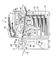
図1において、1は画像形成装置としての複写機、2は原稿Dの画像情報を光学的に読み込む原稿読込部、3は原稿読込部2で読み込んだ画像情報に基いた露光光Lを感光体ドラム5(像担持体)上に照射する露光部、4は感光体ドラム5上にトナー像(画像)を形成する作像部、7は感光体ドラム5上に形成されたトナー像を記録媒体P(用紙)に転写する転写ローラ(転写回転体)、10はセットされた原稿Dを原稿読込部2に搬送する原稿搬送部、12〜14は転写紙等の記録媒体Pが収納された給紙部、17は転写ローラ7と感光体ドラム5とが当接する転写ニップ部に向けて記録媒体Pを搬送するレジストローラ(タイミングローラ)、20は記録媒体P上の未定着画像を定着する定着装置、21は定着装置20に設置された定着ベルト(定着部材)、22は定着装置20に設置された加圧ローラ(加圧部材)、30はオモテ面に画像が形成された後の記録媒体Pを反転して画像形成部に向けて搬送する両面搬送部、を示す。
また、50は画像形成装置本体1から排紙されて搬入された記録媒体Pに後処理を施す後処理装置(用紙処理装置)、61は後処理装置50の内部に設置された積載部(内部トレイ)、71〜73は後処理後の記録媒体P(又は、用紙束)が排出されて積載されるトレイ(排紙トレイ)、86は後処理装置50の内部に設置されて折り処理をおこなうための中折り板(折り処理部)、90は後処理装置50の内部に設置された綴じ装置(ステープル処理部)、95は後処理装置50の内部に設置された穿孔装置(パンチ処理部)、を示す。後処理装置50は、画像形成装置本体1に対して着脱可能に設置されている。
Embodiment 1 FIG.
A first embodiment of the present invention will be described in detail with reference to FIGS.
First, the configuration and operation of the entire image forming apparatus will be described with reference to FIG.
In FIG. 1, 1 is a copying machine as an image forming apparatus, 2 is a document reading unit that optically reads image information of a document D, and 3 is a photosensitive member that exposes light L based on the image information read by the
図1を参照して、作像部4は、像担持体としての感光体ドラム5、帯電ローラ41(帯電装置)、現像装置42、転写回転体としての転写ローラ7、クリーニング装置43、等で構成されている。
詳しくは、像担持体としての感光体ドラム5は、負帯電性の有機感光体であって、ドラム状導電性支持体上に感光層等を設けたものである。図示は省略するが、感光体ドラム5は、基層としての導電性支持体上に、絶縁層である下引き層、感光層としての電荷発生層及び電荷輸送層が順次積層されている。感光体ドラム5は、不図示の駆動モータによって駆動されて、所定方向(図1の時計方向である。)に回転(走行)する。
帯電ローラ41は、導電性芯金の外周に中抵抗の弾性層を被覆してなるローラ部材であって、感光体ドラム5に当接するように配置されている。帯電ローラ41には不図示の帯電用電源部から所定の帯電バイアスが印加されて、これにより対向する感光体ドラム5の表面を一様に帯電する。
Referring to FIG. 1, the
Specifically, the
The
現像装置42は、主として、感光体ドラム5に対向する現像ローラと、仕切部材を介して並設された2つの搬送スクリュ、現像ローラに対向するドクターブレードと、で構成される。現像ローラは、内部に固設されてローラ周面に磁極を形成するマグネットと、マグネットの周囲を回転するスリーブと、で構成される。マグネットによって現像ローラ(スリーブ)上に複数の磁極が形成されて、現像ローラ上に現像剤が担持されることになる。現像装置42内には、キャリアとトナーとからなる2成分現像剤が収容されている。また、図示は省略するが、現像装置42には、トナー容器(新品のトナーが収容されている。)が着脱可能(交換可能)に設置されている。
このように構成された現像装置42によって、現像ローラが感光体ドラム5に対向する位置(現像領域である。)で、現像領域に形成された電界によって、感光体ドラム5上に形成された静電潜像に向けて現像ローラ上のトナーが移動する。こうして、感光体ドラム5上に所望のトナー像が形成されることになる。
The developing
With the developing
なお、本実施の形態1において用いられるトナーは、高速機用のものであって、低融点トナーである。
具体的に、本実施の形態1におけるトナーは、結着樹脂を含有し、結着樹脂が少なくとも、結晶性を有するポリエステル樹脂(A)と、非結晶性樹脂(B)と、非結晶性樹脂(C)と、縮重合系樹脂ユニット及び付加重合系樹脂ユニットを含む複合樹脂(D)とを含み、その非結晶性樹脂(B)はクロロホルム不溶分を含有し、非結晶性樹脂(C)は非結晶性樹脂(B)よりも軟化温度(T1/2)が25℃以上低く、このトナーのTHF可溶分により求められたGPCによる分子量分布において1000〜10000の間にメインピークを有し、その分子量分布の半値幅が15000以下に設定されたものである。
このようなトナーは、上述したように低融点であって高速の画像形成装置用のトナーとして適している反面、紙粉が付着するなどして帯電量が低下して転写ローラ7に付着しやすいものであるため、後述する本願発明による効果(転写ローラ7に付着したトナーを効率的にクリーニングする効果である。)が特に有用に発揮されることになる。
The toner used in the first embodiment is for a high speed machine and is a low melting point toner.
Specifically, the toner in Embodiment 1 contains a binder resin, and the binder resin is at least a crystalline polyester resin (A), an amorphous resin (B), and an amorphous resin. (C) and a composite resin (D) containing a condensation polymerization resin unit and an addition polymerization resin unit, the amorphous resin (B) containing chloroform insoluble matter, and the amorphous resin (C) Has a softening temperature (T1 / 2) lower than that of the amorphous resin (B) by 25 ° C. or more, and has a main peak between 1000 and 10,000 in the molecular weight distribution by GPC determined by the THF soluble content of this toner. The half-value width of the molecular weight distribution is set to 15000 or less.
As described above, such toner has a low melting point and is suitable as a toner for a high-speed image forming apparatus, but on the other hand, the amount of electrification decreases due to adhesion of paper dust and the like, and easily adheres to the
クリーニング装置43には、感光体ドラム5に当接して感光体ドラム5の表面に付着した付着物(主として、未転写トナーである。)を除去するクリーニングブレードが設置されている。クリーニングブレードは、ウレタンゴム、ヒドリンゴム、シリコーンゴム、フッ素ゴム等のゴム材料からなる板状のブレード本体が保持板に保持されたものであって、感光体ドラム5表面に所定角度かつ所定圧力で当接している。これにより、感光体ドラム5上に付着する未転写トナーが機械的に掻き取られてクリーニング装置43内に回収されることになる。
なお、本実施の形態1において、クリーニング装置43で除去・回収された未転写トナーをリサイクルトナーとして現像装置42に供給するためのリサイクル経路を設置することもできる。
The
In the first embodiment, a recycling path for supplying untransferred toner removed and collected by the
転写回転体としての転写ローラ7は、導電性芯金の外周に抵抗値(温湿度が23℃50%RHで、直流電圧1000Vを印加したときの抵抗値である。)が106〜109Ω程度の弾性層を被覆してなるローラ部材であって、感光体ドラム5に圧接して転写ニップ部を形成している。また、転写ローラ7は、不図示の駆動モータによって駆動されて、所定方向(図1の反時計方向である。)に回転する。なお、本実施の形態1では、駆動モータによって転写ローラ7を回転駆動するように構成したが、駆動モータを設置することなく、感光体ドラム5との摩擦力によって転写ローラ7が従動回転するように構成することもできる。
The
また、画像形成装置1には、転写ローラ7(転写回転体)に転写バイアスを印加して、転写ニップ部に搬送される記録媒体Pに感光体ドラム5に担持されたトナー像を転写するバイアス印加手段としての電源部35(転写ローラ用電源部)が設けられている。詳しくは、転写ローラ7(転写回転体)には電源部35から所定の転写バイアス(トナーの極性とは異なる極性のバイアスであって、本実施の形態1ではプラス極性のバイアスである。)が印加されて、転写ニップ部に搬送(挟持)される記録媒体Pに感光体ドラム5上のトナー像(画像)が転写されることになる。
The image forming apparatus 1 also applies a transfer bias to the transfer roller 7 (transfer rotator) to transfer the toner image carried on the
なお、本実施の形態1において、電源部35(バイアス印加手段)は、定電流制御によって転写バイアスを転写ローラ7に印加する電流源である。このように定電流制御をおこなっている転写装置においては、通紙時に流れる電流値を一定にするように転写ローラ7に印加する転写バイアスを調整している。そして、記録媒体Pの裏面(トナー像が転写されない側の面である。)にトナーの極性とは異なる逆電荷を与えることにより、感光体ドラム5上のトナー像を電気的に記録媒体Pの表面に引き寄せることになる。
そして、感光体ドラム5と転写ローラ7との間に転写ニップ部を形成して感光体ドラム5から直接的に記録媒体Pにトナーを転写する直接転写方式の転写装置では、転写ニップ部に記録媒体Pが介在されていない状態で感光体ドラム5に転写ローラ7が直接的に接触することになる。そのため、その状態で転写ローラ7に転写バイアスを印可してしまうと、感光体ドラム5の表面に付着した地汚れトナー(トナーの帯電が不充分であったり機械的な圧力が加わることにより、感光体ドラム5への付着を予定していない非画像部に付着するトナーである。)が転写ローラ7に付着して、転写ローラ7がトナーで汚れてしまうことになる。そして、転写ローラ7がトナーで汚れてしまうと、そのトナーが転写ニップ部に搬送される記録媒体Pの裏面やコバ面に付着してしまうことになる。
そのため、本実施の形態1では、後述するように紙間などで転写ローラ7に転写電流が流れないように制御したりクリーニングバイアスを印可したりして、転写ローラ7にトナーを付着させないようにしたり、転写ローラ7に付着したトナーを感光体ドラム5に移動させてクリーニングしたりしている。
In the first embodiment, the power supply unit 35 (bias applying unit) is a current source that applies a transfer bias to the
In a direct transfer type transfer device in which a transfer nip portion is formed between the
For this reason, in the first embodiment, as will be described later, the toner is not adhered to the
図1を参照して、画像形成装置本体1における、通常の画像形成時の動作について説明する。
まず、原稿Dは、原稿搬送部10の搬送ローラによって、原稿台から図中の矢印方向に搬送されて、原稿読込部2上を通過する。このとき、原稿読込部2では、上方を通過する原稿Dの画像情報が光学的に読み取られる。
そして、原稿読込部2で読み取られた光学的な画像情報は、電気信号に変換された後に、露光部3(書込部)に送信される。そして、露光部3からは、その電気信号の画像情報に基づいたレーザ光等の露光光Lが、作像部4の感光体ドラム5上に向けて発せられる。
With reference to FIG. 1, an operation during normal image formation in the image forming apparatus main body 1 will be described.
First, the document D is conveyed from the document table in the direction of the arrow in the drawing by the conveyance roller of the
Then, the optical image information read by the
一方、作像部4において、感光体ドラム5は図中の時計方向に回転しており、所定の作像プロセス(帯電工程、露光工程、現像工程)を経て、感光体ドラム5上に画像情報に対応した画像(トナー像)が形成される。
その後、感光体ドラム5上に形成された画像は、転写ローラ7との転写ニップ部で、レジストローラ17により搬送された記録媒体P上に転写される。
On the other hand, in the
Thereafter, the image formed on the
一方、転写ローラ7の位置(転写ニップ部)に搬送される記録媒体Pは、次のように動作する。
まず、画像形成装置本体1の複数の給紙部12、13、14のうち、1つの給紙部が自動又は手動で選択される(例えば、最上段の給紙部12が選択されたものとする。)。
そして、給紙部12に収納された記録媒体Pの最上方の1枚が、搬送経路K1の位置に向けて搬送される。
On the other hand, the recording medium P conveyed to the position of the transfer roller 7 (transfer nip portion) operates as follows.
First, one of the plurality of
Then, the uppermost sheet of the recording medium P stored in the
その後、記録媒体Pは、複数の搬送ローラが配設された搬送経路K1を通過して、レジストローラ17の位置に達する。そして、レジストローラ17の位置に達した記録媒体Pは、感光体ドラム5上に形成された画像と位置合わせをするためにタイミングを合わせて、転写ニップ部(転写ローラ7)に向けて搬送される。
Thereafter, the recording medium P passes through a conveyance path K1 in which a plurality of conveyance rollers are arranged, and reaches the position of the
そして、転写工程後の記録媒体Pは、転写ニップ部の位置を通過した後に、搬送経路を経て定着装置20に達する。定着装置20に達した記録媒体Pは、定着ベルト21と加圧ローラ22との間に送入されて、定着ベルト21から受ける熱と双方の部材21、22から受ける圧力とによって画像が定着される。画像が定着された記録媒体Pは、定着ベルト21と加圧ローラ22との間(定着ニップ部である。)から送出された後に、画像形成装置本体1から排出される。
Then, the recording medium P after the transfer process reaches the fixing
なお、記録媒体Pの両面(オモテ面とウラ面とである。)へのプリントをおこなう「両面プリントモード」が選択されている場合には、オモテ面への定着工程が終了した記録媒体Pは、上述した「片面プリントモード」が選択されているときのようにそのまま排紙されることなく、両面搬送経路K2に導かれて、両面搬送部30で搬送方向が反転された後に、再び転写ニップ部(転写ローラ7)の位置に向けて搬送される。そして、転写ニップ部の位置で先に説明したものと同様の画像形成プロセスによって記録媒体Pのウラ面への画像形成がおこなわれ、その後に定着装置20での定着工程を経て、搬送経路を通過して、画像形成装置本体1から排出される。
Note that when “double-sided printing mode” for performing printing on both sides (front side and back side) of the recording medium P is selected, the recording medium P that has completed the fixing process on the front side is Then, the sheet is not discharged as it is when the “single-sided printing mode” is selected, but is guided to the double-sided conveyance path K2, and the conveyance direction is reversed by the double-
ここで、本実施の形態1における画像形成装置は、画像形成装置本体1に後処理装置50が設置されていて、画像形成装置本体1から排出された記録媒体Pが後処理装置50に搬送されて、搬送された記録媒体Pに対して後処理が施されることになる。
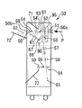
図1を参照して、本実施の形態1における後処理装置50は、装置本体1から搬送された記録媒体Pを3つの搬送経路K3〜K5のうちいずれかの搬送経路に搬送して、異なる後処理を施せるように構成されている。第1の搬送経路K3は、画像形成装置本体1から搬送された記録媒体Pに、後処理を施すことなくそのまま第1排紙トレイ71に排紙するか、穿孔装置95によるパンチ処理のみをおこなって第1排紙トレイ71に排紙するか、するための搬送経路である。第2の搬送経路K4は、画像形成装置本体1から搬送された記録媒体Pを積載部61(内部トレイ)に積載して、綴じ装置90による用紙後端への綴じ処理をおこない、処理後の記録媒体P(用紙束PT)を排紙ローラ55によって排紙口50bから外部トレイ72(第2排紙トレイ)に向けて排紙するための搬送経路である。第3の搬送経路K5は、画像形成装置本体1から搬送された記録媒体Pを一旦第2の搬送経路K4に搬送してスイッチバックした後に、中折り板86、用紙折りブレード84等による中折り処理をおこない、第3排紙トレイ73に排紙するための搬送経路である(図2をも参照できる)。
なお、上述した3つの搬送経路K3〜K5の切替は、分岐爪81の切替動作(回動)によっておこなわれる。また、第2、第3の搬送経路K4、K5にて記録媒体Pを搬送するときにも、第1の搬送経路K3にて記録媒体Pを搬送するときと同様に、穿孔装置95によるパンチ処理を合わせておこなうことができる。
Here, in the image forming apparatus according to the first embodiment, the
Referring to FIG. 1, a
The above-described switching of the three transport paths K3 to K5 is performed by a switching operation (rotation) of the
さらに詳しくは、図2を参照して、後処理装置50の搬入口50aの近傍には、第1搬送ローラ51や紙検知センサが設置されていて、紙検知センサによって検知された記録媒体Pが第1、第2搬送ローラ51、52によって装置50内に搬送される。このとき、予めユーザーによってパンチ処理が選択されているときには、穿孔装置95によるパンチ処理が記録媒体Pに施されることになる。
そして、予めユーザーによって選択された後処理のモードに基いて、記録媒体Pが所望の搬送経路K3〜K5に導かれるように分岐爪81が回動する。
後処理を施さないモードが選択されている場合、第1の搬送経路K3に搬送された記録媒体Pは、第3搬送ローラ53によって排紙されて、第1排紙トレイ71上に排出される。
More specifically, referring to FIG. 2, a
Then, based on the post-processing mode selected in advance by the user, the branching
When the mode in which no post-processing is performed is selected, the recording medium P transported to the first transport path K3 is discharged by the
「ソートモード(仕分け処理モード)」が選択されている場合、第2の搬送経路K4に搬送された記録媒体Pは、幅方向(図2の紙面垂直方向である。)に移動可能に構成された第4搬送ローラ54によって記録媒体Pごとに所定量だけ幅方向にシフト移動されながら搬送されて、排紙ローラ55(第5搬送ローラ)によって搬送されて外部トレイ72(第2排紙トレイ)上に順次積載される。 When the “sort mode (sorting processing mode)” is selected, the recording medium P transported to the second transport path K4 is configured to be movable in the width direction (the direction perpendicular to the paper surface in FIG. 2). The fourth transport roller 54 is transported while being shifted in the width direction by a predetermined amount for each recording medium P, and is transported by the paper discharge roller 55 (fifth transport roller) to be external tray 72 (second paper discharge tray). It is sequentially loaded on top.
図2を参照して、外部トレイ72の上方にはフィラー82が上端の支軸を中心にして回動可能に設けられていて、外部トレイ72は不図示の移動機構によって上下動可能に構成されている。そして、外部トレイ72上に順次積載される記録媒体Pの搬送方向中央部がフィラー82に接触した状態が、フィラー82の支軸近傍に設置されたセンサによって検知されることで、外部トレイ72上に積載された記録媒体Pの高さが認識される。そして、外部トレイ72上に積載される記録媒体Pの枚数の増減に合わせて、外部トレイ72の上下位置が調整されることになる。また、外部トレイ72の上下位置が下限位置に達した場合には、外部トレイ72上に積載された記録媒体Pの枚数が上限(満杯)に達したものとして、後処理装置50から画像形成装置1に停止信号を送信して、画像形成動作を停止させる。なお、前述した後処理や後述する後処理を含めて後処理装置50における一連の後処理動作がおこなわれている間は、画像形成装置本体1は連続的に稼働していて、実際に感光体ドラム5上で作像プロセスがおこなわれていない間も感光体ドラム5や転写ローラ7などの作像部材は空駆動されている。
Referring to FIG. 2, a
「綴じ処理モード(ステイプルモード)」が選択されている場合、第2の搬送経路K4に搬送された記録媒体Pは、第4搬送ローラ54によってシフト移動をおこなうことなく搬送されて、積載部61(内部トレイ)上に順次積載される。そして、積載部61の載置面62上に所望の枚数の記録媒体P(用紙束)が積載されると、その上方に配置された叩きローラ64が最上方の記録媒体Pに当接する位置に移動して、叩きローラ64が図2の反時計方向に回転駆動されることで、複数枚の記録媒体P(用紙束)がフェンス部66に向けて搬送(移動)される。これにより、複数枚の記録媒体P(用紙束)の後端(搬送方向後端)がフェンス部66に突き当たって、複数枚の記録媒体Pの搬送方向の位置が揃えられることになる。
When the “binding processing mode (staple mode)” is selected, the recording medium P transported to the second transport path K4 is transported by the fourth transport roller 54 without being shifted, and the stacking
このとき、図2を参照して、積載部61の幅方向両端部に設置されたジョガーフェンス68が、積載部61上に積載された複数枚の記録媒体Pを挟み込むように幅方向に移動して、複数枚の記録媒体Pの幅方向の位置が揃えられることになる。そして、搬送方向と幅方向とがそれぞれ揃えられた記録媒体P(用紙束)の後端に対して、綴じ装置90によって綴じ処理が施されることになる。
その後、綴じ処理が施された記録媒体P(用紙束)は、放出爪67の排紙方向の移動によって載置面62の傾斜に沿って斜め上方に移動して、排紙ローラ55による搬送によって、外部トレイ72上に排出される。
At this time, referring to FIG. 2,
Thereafter, the recording medium P (sheet bundle) subjected to the binding process moves obliquely upward along the inclination of the mounting surface 62 by the movement of the
「折り処理モード」が選択されている場合、記録媒体Pは、まず第2の搬送経路K4に搬送されて、その後端部が第4搬送ローラ54に挟持された状態で、第4搬送ローラ54を逆回転させることでスイッチバックさせて、第3の搬送経路K5に搬送される。そして、第3の搬送経路K5に搬送された記録媒体Pは、第6〜第8搬送ローラ56〜58によって、記録媒体Pの中央部が用紙折りブレード84に対向する位置まで搬送される。このとき、記録媒体Pは、その先端部がストッパ部85(不図示のスライド機構によって搬送方向に移動可能に構成されている。)に突き当たった状態になっている。そして、その位置に所望の枚数の記録媒体P(用紙束)が積載される。
そして、記録媒体P(用紙束)は、図2の左方に移動する用紙折りブレード84によって中央部が中折りされた状態で、中折り板86の位置で圧接されて、中折り処理が施されることになる。その後、折り処理後の記録媒体P(用紙束)は、第9搬送ローラ59によって搬送されて、その後に第3排紙トレイ73上に排出されることになる。
When the “folding processing mode” is selected, the recording medium P is first transported to the second transport path K4 and the fourth transport roller 54 is in a state where the rear end portion is sandwiched between the fourth transport rollers 54. Is reversely rotated to be switched back and conveyed to the third conveyance path K5. Then, the recording medium P transported to the third transport path K5 is transported by the sixth to
Then, the recording medium P (sheet bundle) is pressed at the position of the
ここで、本実施の形態1における画像形成装置本体1に設置された定着装置20は、定着部材としての定着ベルト21、定着ベルト21の内周面に対向するように配設された不図示の金属パイプ、金属パイプの中空部に設置された不図示のハロゲンヒータ、定着ベルト21の内部に設置されて定着ベルト21を介して加圧ローラ22に圧接して定着ニップ部を形成する不図示の固定部材、加圧部材としての加圧ローラ22、加圧ローラ22の表面温度を検知する温度センサ28、等で構成される。
定着ベルト21は、薄肉で可撓性を有する無端状ベルトであって、図1の時計方向に回転(走行)する。定着ベルト21は、基材上に弾性層、離型層が順次積層されていて、その全体の厚さが1mm以下に設定されている。
定着ベルト21の内部に設置されたハロゲンヒータは、定着ベルト21表面に対向するサーミスタによるベルト表面温度の検知結果に基いて出力制御される。そして、ハロゲンヒータの輻射熱によって、金属パイプを介して定着ベルト21が所望の温度(定着温度)に加熱されることになる。そして、加熱された定着ベルト21の表面から記録媒体P上のトナー像に熱が加えられて、記録媒体P上のトナー像が定着されることになる。
加圧部材としての加圧ローラ22は、ステンレス鋼やアルミニウムなどからなる中空構造の芯金上に、発泡性シリコーンゴムやシリコーンゴムなどからなる弾性層を形成したものであり、図1の反時計方向に回転駆動される。
Here, the fixing
The fixing
The halogen heater installed inside the fixing
The
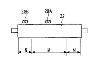
ここで、本実施の形態1では、図3に示すように、加圧ローラ22の表面温度を検知する温度センサとして、2つの温度センサ28A、28Bが幅方向中央部と幅方向端部とにそれぞれ設置されている。第1温度センサ28Aは加圧ローラ22の幅方向中央部の温度を検知するものであって、第2温度センサ28Bは加圧ローラ22の幅方向端部の温度を検知するものである。そして、記録媒体Pとして小サイズ紙が連続通紙される場合などに、小サイズ紙の通紙領域Mに対応する加圧ローラ22の温度を第1温度センサ28Aで検知して、小サイズ紙の非通紙領域Nに対応する加圧ローラ22の温度を第2温度センサ28Bで検知して、双方の検知結果を比較して非通紙領域Nが過昇温状態になっていることが検出されると、記録媒体Pとして大サイズ紙が続けて連続通紙されるまでの紙間を長く設定する制御(定着温度調整モードである。)がおこなわれる。これにより、大サイズ紙に対する定着工程時に、幅方向両端部(小サイズ紙の非通紙領域Nに相当する部分である。)にホットオフセットなどの定着不良が生じる不具合を軽減することができる。特に、本実施の形態1における定着装置20は、熱源(ヒータ)から定着部材への熱伝達効率を高めた省エネルギータイプの定着装置であって、定着部材の幅方向の熱拡散量が少なく、非通紙領域Nの過昇温が生じやすいため、上述したような定着温度制御モードが有用になる。なお、この定着温度調整モード時における転写ローラ用電源部35の制御については、後で図6を用いて説明する。
Here, in the first embodiment, as shown in FIG. 3, two temperature sensors 28 </ b> A and 28 </ b> B are provided at the center in the width direction and the end in the width direction as temperature sensors for detecting the surface temperature of the
なお、本実施の形態1では、加圧ローラ22の幅方向中央部と幅方向端部とにそれぞれ対向するように温度センサ28A、28Bを設けて、定着装置20の非通紙領域Nの温度条件を検知した。これに対して、定着ベルト21の幅方向中央部と幅方向端部とにそれぞれ対向するように温度センサを設けて、定着装置20の非通紙領域Nの温度条件を検知することもできる。
また、本実施の形態1では、定着部材として定着ベルトが設置されて、加圧部材として加圧ローラが設置されて、加熱手段としてハロゲンヒータが設置された定着装置20を用いたが、種々の方式の定着装置を用いることができる。例えば、定着部材として定着ローラが設置された定着装置を用いることもできるし、加圧部材として加圧ベルトが設置された定着装置を用いることもできるし、加熱手段として励磁コイルや抵抗発熱体が設置された定着装置を用いることもできる。
In the first embodiment, the
In the first embodiment, the fixing
以下、図4〜図10等を用いて、本実施の形態1において特徴的な、画像形成装置1の構成・動作について詳述する。
図4は、連続通紙時における転写ローラ7用の電源部35(バイアス印加手段)の制御を示すタイミングチャートである。
本実施の形態1におけるバイアス印加手段としての電源部35(図1を参照できる。)は、転写ローラ7(転写回転体)に付着したトナーをクリーニング(除去)するためのクリーニングバイアスを転写ローラ7に印可できるように構成されている。詳しくは、電源部35は、転写ローラ7に流す転写電流の値を可変できるように構成されている。具体的に、CPU、RAM、ROM等が設置された制御部(制御手段)による制御によって、電源部35から転写ローラ7に印加する転写電流が適宜に可変される。
Hereinafter, the configuration and operation of the image forming apparatus 1 that are characteristic in the first embodiment will be described in detail with reference to FIGS.
FIG. 4 is a timing chart showing the control of the power supply unit 35 (bias applying unit) for the
The power supply unit 35 (see FIG. 1) serving as a bias applying unit in the first embodiment uses a cleaning bias for cleaning (removing) the toner attached to the transfer roller 7 (transfer rotator). It can be applied to. Specifically, the
そして、本実施の形態1における電源部35(バイアス印加手段)は、感光体ドラム5(像担持体)と転写ローラ7(転写回転体)とが駆動された状態で複数の記録媒体Pが連続的に搬送されるとき(連続通紙時である。)であって転写ニップ部において記録媒体Pが送出されてから次の記録媒体が送入されるまでの紙間時間を変数X(msec)として、転写ローラ7にクリーニングバイアスが印可される「クリーニングモード」の実行時間を固定値Y(msec)としたときに、所定条件によって可変される変数Xから固定値Yを減じた値(X−Y)が予め定められた閾値A(msec)を超える場合(X−Y>A)に、その紙間時間中にクリーニングモードが実行されるように制御される。
In the power source unit 35 (bias applying unit) in the first embodiment, a plurality of recording media P are continuously connected while the photosensitive drum 5 (image carrier) and the transfer roller 7 (transfer rotator) are driven. The time between sheets from when the recording medium P is sent at the transfer nip to when the next recording medium is fed is a variable X (msec). Assuming that the execution time of the “cleaning mode” in which the cleaning bias is applied to the
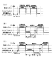
具体的に、図4(B)、(C)に示すように、
(紙間時間X)−(クリーニングモード実行時間Y)>(閾値A)
なる関係が満足される紙間時間X1、X2(>Y+A)で通紙がされるときには、その紙間の時間帯で時間Yだけクリーニングモードが実行される。すなわち、上式の関係が満足されるときには、紙間時間Xの長さに関わらず、同じ時間Yのクリーニングモードが実行されることになる。そして、紙間時間Xのうち、クリーニングモードが実行される時間Y以外の時間Z(=X−Y)には、非画像部バイアスが印可される。
これに対して、図4(A)に示すように、上式の関係が満足されない紙間時間X0(≦Y+A)で通紙がされるときには、その紙間の時間帯ではクリーニングモードが実行されない。
なお、上式におけるクリーニングモード実行時間Yは、1回の紙間時間帯で複数回に分けてクリーニングモードを実行する場合には、その総和の実行時間となる。
Specifically, as shown in FIGS. 4B and 4C,
(Paper interval time X)-(cleaning mode execution time Y)> (threshold A)
When the paper is passed at the inter-paper times X1, X2 (> Y + A) where the above relationship is satisfied, the cleaning mode is executed for the time Y in the time zone between the papers. That is, when the relationship of the above expression is satisfied, the cleaning mode of the same time Y is executed regardless of the length of the inter-paper time X. The non-image portion bias is applied at a time Z (= XY) other than the time Y at which the cleaning mode is executed in the paper interval time X.
On the other hand, as shown in FIG. 4A, when the paper is passed in the paper interval time X0 (≦ Y + A) where the relationship of the above expression is not satisfied, the cleaning mode is not executed in the time zone between the papers. .
It should be noted that the cleaning mode execution time Y in the above equation is the total execution time when the cleaning mode is executed in a plurality of times during one paper interval.
ここで、閾値Aは、転写ニップ部において記録媒体Pの搬送位置ズレが生じる場合や、転写ローラ7に印可するバイアスの切り替え時間などを考慮して、予め設定された値である。この閾値Aが小さすぎると、記録媒媒体Pが転写ニップ部に送出入されるタイミングとクリーニングモードのタイミングとが重なって画像部出力が間に合わなくなってしまう不具合などが生じる可能性があり、閾値Aが大きすぎると、クリーニングモードの実行頻度が低下してしまう可能性があるため、閾値Aを適切な値に決める必要がある。
Here, the threshold value A is a value set in advance in consideration of a case where a conveyance position deviation of the recording medium P occurs in the transfer nip portion, a switching time of a bias applied to the
このように、本実施の形態1では、長時間の紙間にて制御される場合であっても、転写ローラ7にクリーニングバイアスが印可されて、転写ローラ7に付着したトナーを紙間中に感光体ドラム5に再移動(付着)させることができるため、記録媒体Pの裏面やコバ面が汚れる不具合を確実に軽減することができる。また、定められた紙間時間Xの範囲内で、クリーニングバイアスを印可する時間Yを確保できるときにのみクリーニングモードを実行して、クリーニングモードを実行するために紙間時間Xをわざわざ長く設定するような制御はおこなっていないため、クリーニングモードによって連続通紙時の生産性を低下される不具合も生じない。
また、クリーニングモードを実行する場合に、紙間時間Xが長くても、転写ローラ7にクリーニングバイアスを印可する時間Yを固定値としているため、紙間にて転写ローラ7に直接的に接触する感光体ドラム5に対してバイアスによるダメージ(電気的なハザード)が大きくなって、スジ画像などが発生してしまう不具合も軽減することができる。
なお、図4(A)に示すように、紙間時間X0が短い場合には、クリーニングモードによる積極的な転写ローラ7のクリーニング動作はおこなわれないことになる。しかし、紙間時間X0が短い場合には、そもそも紙間において感光体ドラム5から転写ローラ7に移動するトナー量も少なく、転写ローラ7に付着した少量のトナーは、次に搬送される記録媒体Pに目立たないレベルで付着して除去(セルフクリーニング)されることになる。
As described above, in the first embodiment, the cleaning bias is applied to the
Further, when the cleaning mode is executed, even if the paper interval time X is long, the time Y during which the cleaning bias is applied to the
As shown in FIG. 4A, when the paper interval time X0 is short, the aggressive cleaning operation of the
ここで、クリーニングモード実行時間としての固定値Yは、転写ローラ7(転写回転体)が少なくとも1回転以上する時間に設定されている。このように、クリーニングバイアスを転写ローラ7に1周以上かけることで、転写ローラ7の全周の汚れをクリーニングすることができる。ただし、1周分だけでは転写ローラ7の汚れを取りきれない場合もあるため、本実施の形態1では、3.9周分のクリーニングバイアス(負極となる第1クリーニングバイアスを3周分と、正極となる第2クリーニングバイアスを0.9周分である。)を転写ローラ7に印可している。
これらのクリーニングバイアス印加時間(固定値Y)が長いとクリーニング効果がより得られることになるが、上式における判定でクリーニングモードが実行されにくくなったり、上述した感光体ドラム5へのダメージを与えたりすることになるため、適切な時間を設定する必要がある。
Here, the fixed value Y as the cleaning mode execution time is set to a time during which the transfer roller 7 (transfer rotator) rotates at least once. In this way, by applying the cleaning bias to the
When these cleaning bias application times (fixed value Y) are long, a cleaning effect is further obtained. However, it is difficult to execute the cleaning mode according to the determination in the above formula, or damage to the
また、図4を参照して、本実施の形態1において、クリーニングモードは、正極の転写バイアスとは逆の極性(負極)のバイアスを第1クリーニングバイアスとして転写ローラ7に印加した後に、転写バイアスと同じ極性(正極)のバイアスを第2クリーニングバイアスとして転写ローラ7に印加するモードとしている。
これは、感光体ドラム5上に付着する地汚れトナーには、正常に帯電したものの他に、逆帯電したものも少量存在して、これらのトナーが紙間で転写ローラ7に付着することになるためである。そして、転写ローラ7に付着した正常帯電(マイナス帯電)のトナーに対しては、転写ローラ7に負極の第1クリーニングバイアスを印可することで、感光体ドラム5に戻すことができる。これに対して、転写ローラ7に付着した逆帯電(プラス帯電)のトナーに対しては、転写ローラ7に正極の第2クリーニングバイアスを印可することで、感光体ドラム5に戻すことができる。このような制御をおこなうことで、転写ローラ7に付着したトナーをきれいに除去することができる。
Referring to FIG. 4, in the first embodiment, the cleaning mode is performed by applying a bias having a polarity (negative electrode) opposite to the positive transfer bias to the
This is because the scumming toner adhering to the
なお、図4を参照して、クリーニングバイアスは、その絶対値が、転写バイアス(図中、「記録媒体/画像部」の範囲に印可されるバイアスである。)の絶対値よりも小さく設定している。
これにより、クリーニングバイアスの印可によって感光体ドラム5に与えるダメージを小さくすることができる。
Referring to FIG. 4, the absolute value of the cleaning bias is set to be smaller than the absolute value of the transfer bias (the bias applied in the range of “recording medium / image portion” in the figure). ing.
Thereby, damage to the
ここで、図4を参照して、転写ローラ用電源部35(バイアス印加手段)は、先に説明した条件式に基いて紙間時間中にクリーニングモードが実行される場合に、その紙間時間Xが始まる直後にはクリーニングモードが開始されずに、その紙間時間Xが終わる直前にクリーニングモードが終了するように制御されている。すなわち、紙間時間帯の前半ではなくて、できるだけ紙間時間帯の後半にクリーニングモードが実行されるように制御される。
これは、紙間時間Xが長くなる場合、紙間に入って直ぐにクリーニングモードを実行しても、その紙間が終了するまでに転写ローラ7が再びトナーで汚れてしまう可能性があるからである。
具体的に、紙間が開始されてからクリーニングモードを実行するまでの時間Z´(クリーニングモード実行タイミング)は、
Z´=(紙間時間X)−(固定値Y)−(余裕度B)
=(非画像部バイアス印可時間Z)−(余裕度B)
なる式で求めている。この式で余裕度B(msec)は、固定値とすることもできるし、紙間時間X(変数)に所定の係数を乗じたものとすることもできる。
このような制御をおこなうことで、転写ローラ7が紙間で効率的にクリーニングされることになる。なお、本実施の形態では、上述した余裕度Bに相当する時間も転写ローラ7に非画像部バイアスを印可している。
Here, referring to FIG. 4, the transfer roller power supply unit 35 (bias applying unit) determines the time between sheets when the cleaning mode is executed during the time between sheets based on the conditional expression described above. The cleaning mode is controlled not to be started immediately after X starts, but to be ended immediately before the inter-paper time X ends. That is, control is performed so that the cleaning mode is executed in the second half of the paper interval time zone as much as possible, not in the first half of the paper interval time zone.
This is because, when the paper interval time X becomes long, even if the cleaning mode is executed immediately after entering the paper interval, the
Specifically, the time Z ′ (cleaning mode execution timing) from the start of the sheet interval to the execution of the cleaning mode is:
Z ′ = (interval time X) − (fixed value Y) − (margin B)
= (Non-image part bias application time Z)-(Margin B)
It is calculated by the following formula. In this equation, the margin B (msec) can be a fixed value, or can be a value obtained by multiplying the paper interval time X (variable) by a predetermined coefficient.
By performing such control, the
また、図4を参照して、本実施の形態1において、転写ローラ用電源部35(バイアス印加手段)は、紙間時間中においてクリーニングモードが実行されていない時間中は、転写ローラ7に流す転写電流(非画像部バイアス)の値が0μAになるように制御されている。また、クリーニングモードが実行されないときであっても、転写工程がおこなわれているとき以外(転写バイアスが転写ローラ7に印可されているとき以外)は、転写ローラ7に流す転写電流の値が0μAになるように制御されている。
これは、次のような理由によるものである。クリーニングモード以外のときに、プラス側に転写電流(非画像部バイアス)を大きく設定してしまうと、正常帯電(マイナス帯電)のトナーを転写ローラ7に過剰に引きつけてしまうことになる。また、マイナス側に転写電流(非画像部バイアス)を大きく設定してしまうと、逆帯電(プラス帯電)のトナーを転写ローラ7に過剰に引き付けてしまうことになる。そして、これらのような場合に、紙間が長くなるほど転写ローラ7へ汚れが蓄積されてしまう可能性がある。紙間時間が開始された直後から0μAの転写電流(非画像部バイアス)を転写ローラ7に印可して、その後に所定のクリーニングバイアスを転写ローラ7に印可することで、転写ローラ7の汚れを効率的に除去して、記録媒体Pの裏面やコバ面のトナー汚れを防止している。
Referring to FIG. 4, in the first embodiment, transfer roller power supply 35 (bias applying means) flows to transfer
This is due to the following reason. If the transfer current (non-image portion bias) is set large on the positive side in a mode other than the cleaning mode, the normally charged (negatively charged) toner will be excessively attracted to the
なお、本実施の形態1では、図4を参照して、記録媒体Pへの転写工程がおこなわれる前(ジョブ前)にも、電源部35から転写ローラ7にクリーニングバイアス(ジョブ前クリーニングバイアス)が印加される。
詳しくは、電源部35(バイアス印加手段)は、画像形成動作(プリント)が開始された直後に、転写ローラ7が1回転する時間以上、転写バイアスよりも絶対値が小さく転写バイアスとは逆の極性のバイアス(ジョブ前クリーニングバイアス)を転写ローラ7に印加するように制御される。
これにより、画像形成動作が開始される前の放置状態において転写ローラ7上に浮遊トナーが付着してしまうような場合であっても、転写工程前に転写ローラ7のトナー汚れを除去することができる。
In the first embodiment, referring to FIG. 4, the cleaning bias (pre-job cleaning bias) is applied from the
Specifically, the power supply unit 35 (bias applying unit) has an absolute value smaller than the transfer bias and opposite to the transfer bias for a time required for one rotation of the
As a result, even if the floating toner adheres to the
ここで、先に説明したように、連続通紙時における紙間時間X(又は、紙間の長さ)は、画像形成装置1における種々の条件(所定条件)によって、制御部によって可変される値である。
そして、本実施の形態1において、その所定条件は、画像形成装置本体1にて画像形成がされた後の記録媒体Pに後処理を施す後処理装置50の稼働条件、転写ニップ部で転写された記録媒体P上のトナー像を定着させる定着装置20における非通紙領域Nの温度条件、感光体ドラム5(像担持体)の近傍の温度条件、のうち少なくとも1つが含まれる。
Here, as described above, the sheet interval time X (or the sheet interval) during continuous sheet passing is varied by the control unit according to various conditions (predetermined conditions) in the image forming apparatus 1. Value.
In the first embodiment, the predetermined condition is transferred by the operating condition of the
詳しくは、本実施の形態1における画像形成装置1では、従来のものと同様に、後処理装置50で複数の記録媒体P(用紙束)に対して綴じ処理や折り処理やパンチ処理おこなわれるときに、用紙束と用紙束との間(紙間であって、特に部間と呼ぶ。)の時間(紙間時間)が特に長く設定される。これは、用紙束に対して後処理を施す充分な時間を確保するためである。
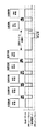
図5は、5枚の記録媒体Pを1セット(1部の用紙束)として後処理装置50で綴じ処理(ステープル処理)をおこなうときの、転写ローラ用電源部35の電流制御を示すタイミングチャートである。このような場合、用紙束と用紙束との紙間時間X3は非常に長く設定されることになるが、その場合にも紙間時間X3の後半に固定された時間Yのクリーニングモードが実行されることになる。
Specifically, in the image forming apparatus 1 according to the first embodiment, when the
FIG. 5 is a timing chart showing current control of the transfer
また、本実施の形態1における画像形成装置1では、先に図3を用いて説明したように、小サイズ紙が連続通紙されて非通紙領域Nの過昇温が検出されたときに、その後に大サイズ紙が通紙される前のタイミングで、定着温度調整モードとしてその紙間が長く設定される。これは、大サイズ紙への定着工程がおこなわれるまでに、定着部材における幅方向の温度分布を均一化するのに充分な時間を確保するためである。
図6は、このように定着装置20にて非通紙領域の過昇温が生じたときの、転写ローラ用電源部35の電流制御を示すタイミングチャートである。このような場合、小サイズ紙の連続通紙後に大サイズ紙が通紙されるときの小サイズ紙と大サイズ紙との紙間時間X4は非常に長く設定されることになるが、その場合にも紙間時間X4の後半に固定された時間Yのクリーニングモードが実行されることになる。
Further, in the image forming apparatus 1 according to the first embodiment, as described above with reference to FIG. 3, when an excessive temperature rise in the non-sheet passing region N is detected as a small size sheet is continuously fed. Then, at the timing before the large-size paper is subsequently passed, the sheet interval is set to be long as the fixing temperature adjustment mode. This is to secure a sufficient time to make the temperature distribution in the width direction of the fixing member uniform before the fixing process to the large size paper is performed.
FIG. 6 is a timing chart showing the current control of the transfer
また、本実施の形態1における画像形成装置1では、図1に示すように感光体ドラム5の近傍の温度を検知する温度検知手段としての温湿度センサ48(後述する環境検知手段としても機能する。)が設置されている。そして、温湿度センサ48によって所定値以上の温度が検知されたときには、連続通紙時の毎回の紙間X5を非常に長く設定して、機内温度の上昇を抑える「低生産性モード」が実施される。これは、機内温度(特に、感光体ドラム5の近傍の温度)が過昇温すると、作像部品にトナーが融解して固着してしまう可能性があるためである。特に、本実施の形態1では、低融点トナーを用いているため、このような問題が無視できなくなっている。
図7は、このように感光体ドラム5の近傍の温度が上昇したときの、転写ローラ用電源部35の電流制御を示すタイミングチャートである。このような場合、連続通紙時における紙間ごとに紙間時間X5が非常に長く設定されることになるが、その場合にもそれぞれの紙間時間X5の後半に固定された時間Yのクリーニングモードが実行されることになる。
なお、このように連続通紙時における紙間ごとに紙間時間Xを長く設定する制御は、記録媒体Pとして厚紙が用いられるときにも一般的におこなわれるものであり、そのような場合にも同じような電源部35の電流制御をおこなうことができる。
また、連続通紙時において紙間時間Xが長く設定される条件(所定条件)は、上述のものに限定されることなく、例えば、先に図1を用いて説明した「両面プリントモード」がおこなわれるときなども該当することになる。
In the image forming apparatus 1 according to the first embodiment, as shown in FIG. 1, a temperature / humidity sensor 48 (which also functions as an environment detection unit described later) functions as a temperature detection unit that detects the temperature in the vicinity of the
FIG. 7 is a timing chart showing current control of the transfer
Note that the control for setting the paper interval time X to be longer for each paper interval during continuous paper passing is generally performed even when thick paper is used as the recording medium P. In such a case, The same current control of the
In addition, the condition (predetermined condition) for setting the paper interval time X to be long during continuous paper feeding is not limited to the above-described one, and for example, the “double-sided printing mode” described above with reference to FIG. This also applies when it is performed.
ここで、本実施の形態1において、転写ニップ部に搬送される記録媒体Pの搬送速度(感光体ドラム5の線速度となるプロセス線速とほぼ同値である。)を可変できるように構成して、その搬送速度(プロセス線速)の大きさに基いてクリーニングバイアスの大きさを調整するように転写ローラ用電源部35(バイアス印加手段)を制御することもできる。
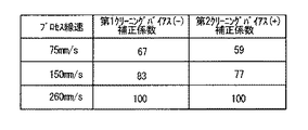
図8は、そのような制御の一例であって、プロセス線速が3段階で可変されるときの、プロセス線速ごとの第1クリーニングバイアスの補正係数と第2クリーニングバイアスの補正係数とを示している。図8の例では、通常時のプロセス線速が260mm/sであって、そのときの補正係数を100として、プロセス線速が減速されたときに、表図の補正係数の比率でバイアスの大きさを減少させている。例えば、プロセス線速が260mm/sのときの第1クリーニングバイアスの大きさに比べて、プロセス線速が150mm/sのときの第1クリーニングバイアスの大きさは83/100に設定される。
このような制御をおこなうのは、プロセス線速(搬送速度)が変化すると、転写電流値に対する実行バイアスが変化するためであって、プロセス線速ごとに適正なバイアス(電流値)に制御する必要がある。すなわち、このような制御をおこなうことで、プロセス線速(搬送速度)が変化しても、良好で安定して転写ローラ7のクリーニングをおこなうことができる。なお、プロセス線速(搬送速度)を可変するのは、記録媒体Pの紙厚が変化しても良好な定着性や光沢性を高精度に確保したい場合などがある。
Here, the first embodiment is configured such that the conveyance speed of the recording medium P conveyed to the transfer nip portion (approximately the same value as the process linear velocity that is the linear velocity of the photosensitive drum 5) can be varied. Thus, the transfer roller power supply 35 (bias applying means) can be controlled so as to adjust the magnitude of the cleaning bias based on the magnitude of the conveying speed (process linear speed).
FIG. 8 shows an example of such control, and shows the correction coefficient for the first cleaning bias and the correction coefficient for the second cleaning bias for each process line speed when the process line speed is varied in three stages. ing. In the example of FIG. 8, the normal process linear velocity is 260 mm / s, and the correction factor at that time is 100. When the process linear velocity is decelerated, the magnitude of the bias is the ratio of the correction factor shown in the table. Is decreasing. For example, the magnitude of the first cleaning bias when the process linear velocity is 150 mm / s is set to 83/100, compared to the magnitude of the first cleaning bias when the process linear velocity is 260 mm / s.
This control is performed because the execution bias with respect to the transfer current value changes when the process linear speed (conveyance speed) changes. It is necessary to control the bias (current value) to an appropriate value for each process linear speed. There is. That is, by performing such control, even if the process linear speed (conveying speed) changes, the
また、本実施の形態1において、先に説明した温湿度センサ48を温湿度を検知する環境検知手段として用いて、その温湿度センサ48の検出結果(絶対湿度である。)に基いてクリーニングバイアスの大きさを調整するように転写ローラ用電源部35(バイアス印加手段)を制御することもできる。
図9は、そのような制御の一例であって、絶対湿度に基いて可変されるクリーニングバイアス(第1クリーニングバイアスと第2クリーニングバイアスとである。)を示す表図である。
このような制御をおこなうのは、転写ローラ7のトナー汚れは環境による影響が大きくて、絶対湿度が高いときにはその発生頻度が多くなる傾向にあるためである。そのため、図9に示すように、絶対湿度が高いときには、絶対湿度が低いときに比べて、クリーニングバイアス出力(転写電流値)の絶対値を高く設定して、転写ローラ7に対するクリーニング性を高めている。
In the first embodiment, the temperature /
FIG. 9 is an example of such control, and is a table showing cleaning biases (which are a first cleaning bias and a second cleaning bias) that are varied based on absolute humidity.
The reason why such control is performed is that toner contamination on the
最後に、図10を用いて、本願発明者が本願発明における効果を確認するためにおこなった実験について、簡単に説明する。
図10は、経時における記録媒体Pのコバ面汚れのランクの変動についての実験結果を示すグラフである。図10において、横軸は通紙枚数を示すものである。また、図10において縦軸に示すコバ面汚れのランクは、記録媒体Pにおけるコバ面の汚れ方を段階的にランク付けしたもので、許容できるレベルをランク2として、ランク数が上がるごとにそのレベルが向上し、ランク5はコバ面汚れがまったくない状態である。実験は、画像形成装置において最も汚れが発生しやすい条件を選定しておこなっており、温湿度環境は27℃80%でおこなっている。また、転写ローラ7として、交換寿命に到達したものを使用して、プリント速度は30枚/分(CPM)としている。また、図10において、一点鎖線で示すグラフは比較的短い紙間時間(図4(B)の程度である。)でクリーニングモードを実行しない条件でおこなった実験結果であって、破線で示すグラフは比較的長い紙間時間(図5の程度で、10sec程度である。)でクリーニングモードを実行しない条件でおこなった実験結果であって、実線で示すグラフは比較的長い紙間時間(図5の程度で、10sec程度である。)でクリーニングモードを実行する条件(本実施の形態1における制御をおこなう条件である。)でおこなった実験結果である。
図10の結果からも、本実施の形態1における転写ローラ用電源部35の制御をおこなうことで、紙間で転写ローラ7が効率的にクリーニングされて、記録媒体Pのトナー汚れが確実に軽減されることがわかる。
Finally, an experiment conducted by the inventor for confirming the effect of the present invention will be briefly described with reference to FIG.
FIG. 10 is a graph showing the experimental results of the change in the rank of the edge surface contamination of the recording medium P over time. In FIG. 10, the horizontal axis indicates the number of sheets to be passed. In addition, the rank of the edge surface contamination shown on the vertical axis in FIG. 10 is a stepwise ranking of the edge surface contamination on the recording medium P, and the acceptable level is
From the results of FIG. 10 as well, by controlling the transfer
以上説明したように、本実施の形態1では、連続通紙時における紙間時間を変数Xとして、転写ローラ7(転写回転体)にクリーニングバイアスが印可されるクリーニングモードの実行時間を固定値Yとしたときに、所定条件によって可変される変数Xから固定値Yを減じた値(X−Y)が予め定められた閾値Aを超える場合(X−Y>A)に、その紙間時間中にクリーニングモードが実行されるように、転写ローラ用電源部35(バイアス印可手段)を制御している。換言すると、連続通紙時における紙間時間を時間Xとしたとき、時間Xは所定条件によって可変され、時間Xが所定の閾値を超える場合に、紙間時間Xのうち時間Zだけ非画像部バイアスを印可するとともに、時間Y(=X−Z)だけクリーニングバイアスを印可し、時間Xが長いほど時間Zが長くなるように制御している。
これにより、クリーニングバイアスによって感光体ドラム5(像担持体)の劣化が早められることなく、クリーニングモードを実行することで連続通紙時における生産性が低下することなく、感光体ドラム5から移動して転写ローラ7に付着したトナーによって転写ニップ部に搬送される記録媒体Pの裏面やコバ面が汚れる不具合を効率的に軽減することができる。
As described above, in the first embodiment, the time between continuous paper passes is defined as the variable X, and the execution time of the cleaning mode in which the cleaning bias is applied to the transfer roller 7 (transfer rotator) is a fixed value Y. When the value (XY) obtained by subtracting the fixed value Y from the variable X variable according to a predetermined condition exceeds a predetermined threshold A (XY> A), the interval between the papers The transfer roller power supply 35 (bias applying means) is controlled so that the cleaning mode is executed at the same time. In other words, when the inter-paper time at the time of continuous paper feeding is time X, the time X is varied according to a predetermined condition, and when the time X exceeds a predetermined threshold, only the time Z of the inter-paper time X is a non-image portion. A bias is applied, and a cleaning bias is applied only for a time Y (= X−Z), and the time Z is controlled to be longer as the time X is longer.
As a result, the deterioration of the photosensitive drum 5 (image carrier) is not accelerated by the cleaning bias, and the cleaning mode is executed to move the
実施の形態2.
図11にて、この発明の実施の形態2について詳細に説明する。
図11は、実施の形態2における画像形成装置1でおこなわれる転写ローラ用電源部35の制御を示すタイミングチャートであって、前記実施の形態1における図4に相当する。
本実施の形態2では、クリーニングバイアスを印可する時間Yが可変できる値(変数)である点が、クリーニングバイアスを印可する時間Yが固定値に設定されている前記実施の形態1のものとは相違する。
A second embodiment of the present invention will be described in detail with reference to FIG.
FIG. 11 is a timing chart showing the control of the transfer
In the second embodiment, the time Y at which the cleaning bias is applied is a value (variable) that can be varied. This is different from the first embodiment in which the time Y at which the cleaning bias is applied is set to a fixed value. Is different.
本実施の形態2における画像形成装置1でも、前記実施の形態1のものと同様に、転写ローラ用電源部35(バイアス印可手段)は、転写バイアスやクリーニングバイアスや非画像部バイアスを転写ローラ7に適宜に印可できるように構成されている。
また、本実施の形態2における画像形成装置1でも、前記実施の形態1のものと同様に、感光体ドラム5(像担持体)が駆動された状態で複数の記録媒体Pが連続的に搬送されるときであって転写ニップ部において記録媒体Pが送出されてから次の記録媒体が送入されるまでの紙間時間を時間Xとしたとき、その時間Xは所定条件によって可変されている。また、時間X(紙間時間)が所定の閾値を超える場合に、紙間時間Xのうち時間Zだけ非画像部バイアスを印可するとともに、時間(X−Z)だけクリーニングバイアスを印可している。そして、本実施の形態2においても、時間X(紙間時間)が長いほど時間Z(非画像部バイアス印可時間)が長くなるように制御している。
In the image forming apparatus 1 according to the second embodiment, similarly to the first embodiment, the transfer roller power supply unit 35 (bias applying unit) applies the transfer bias, the cleaning bias, and the non-image portion bias to the
Also in the image forming apparatus 1 according to the second embodiment, similarly to the first embodiment, a plurality of recording media P are continuously conveyed while the photosensitive drum 5 (image carrier) is driven. When the time between sheets from the time when the recording medium P is sent at the transfer nip to the time when the next recording medium is sent is defined as time X, the time X is varied according to a predetermined condition. . Further, when the time X (inter-paper time) exceeds a predetermined threshold, the non-image portion bias is applied for the time Z of the inter-paper time X, and the cleaning bias is applied for the time (X−Z). . Also in the second embodiment, control is performed such that the time Z (non-image portion bias application time) becomes longer as the time X (inter-paper time) is longer.
このような制御をおこなうのは、所定条件によって可変される時間X(紙間時間)が長くなる分だけクリーニングバイアスの印加時間も長くしてしまうと、紙間にて転写ローラ7に直接的に接触する感光体ドラム5に対してバイアスによるダメージ(電気的なハザード)が大きくなって、スジ画像などが発生してしまうためである。
これに対して、本実施の形態2では、前記実施の形態1のものと同様に、時間X(紙間時間)が長くなるほど時間Z(非画像部バイアス印可時間)を長くしているため、時間Xが長くなっても、クリーニングバイアスを印加する時間(X−Z)は長くなり過ぎないので、感光体ドラム5に対するダメージを小さくすることができる。
Such control is performed because if the application time of the cleaning bias is increased by the amount of time X (interval time) that is varied depending on a predetermined condition, the
On the other hand, in the second embodiment, as in the first embodiment, the time Z (non-image portion bias application time) is increased as the time X (inter-paper time) is increased. Even if the time X becomes longer, the time (XZ) for applying the cleaning bias does not become too long, so that damage to the
ここで、図11(B)、図11(C)を参照して、本実施の形態2では、前記実施の形態1のものと異なり、紙間時間Xに応じてクリーニングバイアスが印可される時間Y(クリーニングモードを実行する時間である。)を可変している。詳しくは、クリーニングモードが実行される場合であって、紙間時間X2が長い場合には、そのときのクリーニングモード実行時間Y2が、紙間時間X1が短い場合のクリーニングモード実行時間Y1に比べて、少し長くなるようにしている。このように、紙間時間Xの長さに合わせて、クリーニングモードの実行時間Yを微調整することで、より最適なクリーニング性を得ることができる。 Here, referring to FIG. 11B and FIG. 11C, in the second embodiment, unlike the first embodiment, the time during which the cleaning bias is applied according to the inter-paper time X. Y (time for executing the cleaning mode) is varied. Specifically, when the cleaning mode is executed and the inter-paper time X2 is long, the cleaning mode execution time Y2 at that time is longer than the cleaning mode execution time Y1 when the inter-paper time X1 is short. , Trying to be a little longer. In this way, by finely adjusting the execution time Y of the cleaning mode in accordance with the length of the inter-paper time X, a more optimal cleaning property can be obtained.
さらに具体的に、転写ローラ7にクリーニングバイアスが印可される「クリーニングモード」の実行に必要な最小の時間を最小値Y0(msec)としたときに、所定条件によって可変される変数Xから最小値Y0を減じた値(X−Y0)が予め定められた閾値A´(msec)を超える場合(X−Y0>A´)に、その紙間時間中にクリーニングモードが実行されるように制御される。
そして、図11(B)に示すように、
(紙間時間X)−(最小値Y0)>(閾値A´)
なる関係が満足される紙間時間X1(>Y0+A´)で通紙がされるときには、その紙間の時間帯で時間Y1だけクリーニングモードが実行される。また、図11(C)に示すように、上式の関係が満足される紙間時間X2(>X1>Y0+A´)で通紙がされるときには、その紙間の時間帯で時間Y2(>Y1)だけクリーニングモードが実行される。
これに対して、図11(A)に示すように、上式の関係が満足されない紙間時間X0(≦Y0+A´)で通紙がされるときには、その紙間の時間帯ではクリーニングモードが実行されない。
More specifically, when the minimum time required for executing the “cleaning mode” in which the cleaning bias is applied to the
And as shown in FIG.
(Paper time X)-(Minimum value Y0)> (Threshold A ′)
When the paper is passed in the inter-paper time X1 (> Y0 + A ′) that satisfies this relationship, the cleaning mode is executed for the time Y1 in the time zone between the papers. Further, as shown in FIG. 11C, when a sheet is passed at a paper interval time X2 (>X1> Y0 + A ′) that satisfies the relationship of the above equation, the time Y2 (> The cleaning mode is executed only for Y1).
On the other hand, as shown in FIG. 11A, when the paper is passed in the paper interval time X0 (≦ Y0 + A ′) where the relationship of the above expression is not satisfied, the cleaning mode is executed in the time zone between the papers. Not.
上述したように、紙間時間Xが増加した分だけクリーニングバイアスの印加時間Yを増加させる場合、すなわち、時間Zを固定してY2=Y1+(X2−X1)とする場合、紙間時間X(X2)が非常に長いときにクリーニングバイアスの印加時間Y(Y2)も非常に長くなって、その分だけ感光体ドラム5に対してバイアスによるダメージを大きくしてしまう。
これに対して、本実施の形態2では、非画像部バイアス印可時間Zが、紙間時間Xが長いほど長い時間になるように設定されることになる。すなわち、図11(B)、図11(C)に示すように、紙間時間X2が長いときの非画像部バイアス印可時間Z2は、紙間時間X1が短いときの非画像部バイアス印可時間Z1より長くなる(X2>X1、Z2>Z1である。)。そのため、紙間時間X2が長いときであっても、クリーニングバイアス印可時間Y2が長くなり過ぎることがないため、良好なクリーニング性を確保しつつ、感光体ドラム5に対するダメージを小さくすることができる。
なお、上述した最小値Y0は、転写ローラ7(転写回転体)が少なくとも1回転以上する時間に設定されている。そして、紙間時間Xを可変した場合の時間Y1や時間Y2は、最小値Y0以上の時間に設定されている。このように、クリーニングバイアスを転写ローラ7に1周以上かけることで、転写ローラ7の全周の汚れをクリーニングすることができる。
As described above, when the cleaning bias application time Y is increased by the increase in the paper interval time X, that is, when the time Z is fixed and Y2 = Y1 + (X2−X1), the paper interval time X is increased. When (X2) is very long, the cleaning bias application time Y (Y2) also becomes very long, and the damage to the
On the other hand, in the second embodiment, the non-image portion bias application time Z is set to be longer as the paper interval time X is longer. That is, as shown in FIGS. 11B and 11C, the non-image portion bias application time Z1 when the paper interval time X2 is long is the non-image portion bias application time Z1 when the paper interval time X1 is short. It becomes longer (X2> X1, Z2> Z1). Therefore, even when the paper interval time X2 is long, the cleaning bias application time Y2 does not become too long, so that damage to the
Note that the minimum value Y0 described above is set to a time during which the transfer roller 7 (transfer rotator) rotates at least once. The time Y1 and time Y2 when the inter-paper time X is varied are set to a time equal to or greater than the minimum value Y0. In this way, by applying the cleaning bias to the
以上説明したように、本実施の形態2でも、前記実施の形態1と同様に、連続通紙時における紙間時間を時間Xとしたとき、時間Xは所定条件によって可変され、時間Xが所定の閾値Aを超える場合に、紙間時間Xのうち時間Zだけ非画像部バイアスを印可するとともに、時間Y(=X−Z)だけクリーニングバイアスを印可し、時間Xが長いほど時間Zが長くなるように制御している。これにより、クリーニングバイアスによって感光体ドラム5(像担持体)の劣化が早められることなく、クリーニングモードを実行することで連続通紙時における生産性が低下することなく、感光体ドラム5から移動して転写ローラ7に付着したトナーによって転写ニップ部に搬送される記録媒体Pの裏面やコバ面が汚れる不具合を効率的に軽減することができる。
As described above, also in the second embodiment, as in the first embodiment, when the inter-paper time at the time of continuous sheet feeding is the time X, the time X is varied according to a predetermined condition, and the time X is a predetermined time. When the threshold value A is exceeded, the non-image portion bias is applied only for the time Z of the paper interval time X, and the cleaning bias is applied for the time Y (= X−Z). The longer the time X is, the longer the time Z is. It is controlled to become. As a result, the deterioration of the photosensitive drum 5 (image carrier) is not accelerated by the cleaning bias, and the cleaning mode is executed to move the
なお、前記各実施の形態では、作像部4として1つの感光体ドラム5が設置されたモノクロ画像形成装置1に対して本発明を適用したが、作像部として複数色のトナーに対応した複数の感光体ドラムが設置されたカラー画像形成装置に対しても当然に本発明を適用することができる。
また、前記各実施の形態では、像担持体としての感光体ドラム5に担持されたトナー像を記録媒体P上に転写する画像形成装置1に対して本発明を適用した。これに対して、像担持体としての感光体ベルトに担持されたトナー像を記録媒体上に転写する画像形成装置や、像担持体としての中間転写ベルトや中間転写ドラムなどの中間転写体に担持されたトナー像を記録媒体上に転写する画像形成装置に対しても、当然に本発明を適用することができる。
また、前記各実施の形態では、転写回転体として転写ローラ7が設置された画像形成装置1に対して本発明を適用した。これに対して、転写回転体として転写ベルトが設置された画像形成装置や、転写回転体として2次転写ローラが設置された画像形成装置に対しても、当然に本発明を適用することができる。
そして、それらの場合であっても、前記各実施の形態と同様の効果を得ることができる。
In each of the above-described embodiments, the present invention is applied to the monochrome image forming apparatus 1 in which one
Further, in each of the above embodiments, the present invention is applied to the image forming apparatus 1 that transfers the toner image carried on the
In each of the above embodiments, the present invention is applied to the image forming apparatus 1 in which the
Even in those cases, the same effects as those of the above-described embodiments can be obtained.
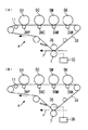
図12(A)と図12(B)とは、いずれも、作像部4として複数色のトナーに対応した複数の感光体ドラム5Y、5M、5C、5Kが設置されたカラー画像形成装置における要部を示す構成図であって、像担持体として中間転写ベルト38が用いられ、転写回転体として2次転写ローラ7が用いられ、さらに像担持体(中間転写ベルト38)を介して転写回転体(2次転写ローラ7)に当接する転写対向回転体(2次転写対向ローラ36)が設置された場合の変形例である。なお、図12(A)と図12(B)とにおいて、画像形成装置における作像部4以外の構成は、図1に示す前記各実施の形態のものとほぼ同様に構成することができるため、その図示と説明を省略する。
詳しくは、4つの1次転写ローラ39Y、39M、39C、39Kは、それぞれ、中間転写ベルト38を感光体ドラム5Y 、5M 、5C 、5K との間に挟み込んで1次転写ニップを形成している。そして、1次転写ローラ39Y、39M、39C、39Kに、トナーの極性とは逆の1次転写電圧(1次転写バイアス)が印加される。
そして、中間転写ベルト38は、破線矢印方向に走行して、1次転写ローラ39Y、39M、39C、39Kの1次転写ニップを順次通過する。こうして、感光体ドラム5Y 、5M 、5C 、5K上に形成された各色のトナー像(前記各実施の形態のものと同様に、帯電工程、露光工程、現像工程を経てそれぞれ形成されたものである。)が、中間転写ベルト38上に重ねて1次転写される。
その後、各色のトナー像が重ねて転写された中間転写ベルト38(像担持体)は、2次転写ローラ7(転写回転体)との対向位置に達する。この位置では、転写対向回転体としての転写対向ローラ36が、2次転写ローラ7との間に中間転写ベルト38を挟み込んで2次転写ニップ(転写ニップ部)を形成している。そして、中間転写ベルト38上に形成された4色のトナー像は、この2次転写ニップ(転写ニップ部)の位置に搬送された記録媒体P上に転写される。
ここで、図12(A)のものは、電源部35から転写回転体としての2次転写ローラ7に、本実施の形態のものとほぼ同様に、転写バイアスやクリーニングバイアスが印可されて、通常の転写工程(2次転写工程)やクリーニングモードがおこなわれることになる。
これに対して、図12(B)のものは、電源部35から2次転写ローラ7ではなくて転写対向回転体としての2次転写対向ローラ36に、転写バイアスやクリーニングバイアスが印可されることになる。この2次転写対向ローラ36に印可される転写バイアスやクリーニングバイアスは、印可されるタイミングについては本実施の形態のものや図12(A)のものと同じものの、その極性はそれぞれ本実施の形態のものや図12(A)のものに対して逆の極性になる。具体的に、図7の例に対応させて説明すると、マイナス極性の転写バイアスが2次転写対向ローラ36に印可されて通常の転写工程がおこなわれて、紙間においてプラス極性の第1クリーニングバイアスが印可された後にマイナス極性の第2クリーニングバイアスが印可されてクリーニングモードが実行されることになる。
なお、図示は省略するが、2次転写ローラ7(転写回転体)と2次転写対向ローラ36(転写対向回転体)とにそれぞれ転写バイアスやクリーニングバイアスや非画像部バイアスを印可して転写工程やクリーニングモードをおこなう場合には、図12(A)のものでおこなわれる転写バイアスやクリーニングバイアスや非画像部バイアスの印可と、図12(B)のものでおこなわれる転写バイアスやクリーニングバイアスや非画像部バイアスの印可と、が同じタイミングでおこなわれることになる。
そして、これらの場合であっても、前記各実施の形態と同様の効果を得ることができる。
12A and 12B are both color image forming apparatuses in which a plurality of
Specifically, the four
The
Thereafter, the intermediate transfer belt 38 (image carrier) onto which the toner images of the respective colors are transferred in an overlapping manner reaches a position facing the secondary transfer roller 7 (transfer rotator). At this position, the
Here, in FIG. 12A, a transfer bias and a cleaning bias are applied to the
On the other hand, in FIG. 12B, the transfer bias and the cleaning bias are applied from the
Although not shown in the drawings, a transfer bias, a cleaning bias, and a non-image portion bias are applied to the secondary transfer roller 7 (transfer rotator) and the secondary transfer counter roller 36 (transfer counter rotator), respectively. In the cleaning mode, the transfer bias, cleaning bias, and non-image portion bias applied in FIG. 12A and the transfer bias, cleaning bias, and non-transfer in FIG. 12B are applied. The image portion bias is applied at the same timing.
Even in these cases, the same effects as those of the above-described embodiments can be obtained.
また、前記各実施の形態では、転写ローラ7に印可する非画像部バイアスの値を0μAとしたが、非画像部バイアスの値はこの値に限定されることなく、クリーニングバイアスよりも絶対値が小さな値であれば、その値のものを転写ローラ7に印可する非画像部バイアスとすることができる。
詳しくは、転写ローラ用電源部35(バイアス印加手段)は、紙間時間中においてクリーニングモードが実行されていない時間Z中は、転写ローラ7に流す転写電流(非画像部バイアス)が所定値になるように制御される。この所定値は、その絶対値が、クリーニングバイアスの絶対値よりも小さく設定されたものであればよい。例えば、クリーニングバイアスが、転写バイアスとは逆の極性の第1クリーニングバイアスと、転写バイアスと同じ極性の第2クリーニングバイアスと、からなる場合には、この所定値の絶対値が第1クリーニングバイアスと第2クリーニングバイアスとのいずれの絶対値よりも小さく設定されることになる。これに対して、クリーニングバイアスが転写バイアスとは逆極性の逆バイアスのみからなる場合には、この所定値の絶対値が、その逆バイアスの絶対値よりも小さく設定されることになる。ただし、この転写電流(非画像部バイアス)は、正常に帯電したトナーはもちろん、逆帯電したトナーも転写ローラ7に引き付けすぎない程度に小さく設定することが好ましい。
また、前記各実施の形態では、転写ローラ用電源部35(バイアス印加手段)を定電流制御したが、転写ローラ用電源部35(バイアス印加手段)を定電圧制御することもできる。この場合、転写ローラ用電源部35(バイアス印加手段)は、非画像部バイアスを印可するときに、非画像部バイアスの値が0Vになるように定電圧制御されることが好ましい。
そして、これらの場合であっても、前記各実施の形態と同様の効果を得ることができる。
In each of the above embodiments, the value of the non-image portion bias applied to the
Specifically, the transfer roller power supply unit 35 (bias applying unit) sets the transfer current (non-image portion bias) flowing through the
In each of the above embodiments, the transfer roller power supply unit 35 (bias application unit) is controlled at a constant current, but the transfer roller power supply unit 35 (bias application unit) can also be controlled at a constant voltage. In this case, it is preferable that the transfer roller power supply unit 35 (bias applying unit) is controlled at a constant voltage so that the non-image portion bias value becomes 0 V when the non-image portion bias is applied.
Even in these cases, the same effects as those of the above-described embodiments can be obtained.
なお、本発明が前記各実施の形態に限定されず、本発明の技術思想の範囲内において、前記各実施の形態の中で示唆した以外にも、前記各実施の形態は適宜変更され得ることは明らかである。また、前記構成部材の数、位置、形状等は前記各実施の形態に限定されず、本発明を実施する上で好適な数、位置、形状等にすることができる。 It should be noted that the present invention is not limited to the above-described embodiments, and within the scope of the technical idea of the present invention, the embodiments can be modified as appropriate in addition to those suggested in the embodiments. Is clear. In addition, the number, position, shape, and the like of the constituent members are not limited to the above embodiments, and can be set to a number, position, shape, and the like that are suitable for carrying out the present invention.
1 画像形成装置(画像形成装置本体)、
5 感光体ドラム(像担持体)、
7 転写ローラ(転写回転体)、
20 定着装置、
21 定着ベルト、 22 加圧ローラ、
28、28A、28B 温度センサ(温度検知手段)、
35 電源部(バイアス印加手段)、
48 温湿度センサ(環境検知手段)、
50 後処理装置、
P 記録媒体(用紙)。
1 image forming apparatus (image forming apparatus main body),
5 Photosensitive drum (image carrier),
7 Transfer roller (transfer rotator),
20 fixing device,
21 fixing belt, 22 pressure roller,
28, 28A, 28B Temperature sensor (temperature detection means),
35 power supply (bias applying means),
48 Temperature / humidity sensor (environment detection means),
50 aftertreatment devices,
P Recording medium (paper).
Claims (11)
所定方向に回転して、前記像担持体に当接して転写ニップ部を形成する転写回転体と、
前記転写回転体、又は/及び、前記像担持体を介して前記転写回転体に当接する転写対向回転体、に転写バイアスを印加して、前記転写ニップ部に搬送される記録媒体にトナー像を転写するバイアス印加手段と、
を備え、
前記バイアス印加手段は、
前記転写回転体に付着したトナーをクリーニングするクリーニングバイアス、及び、前記クリーニングバイアスよりも絶対値の小さな非画像部バイアス、を前記転写回転体又は/及び前記転写対向回転体に印可可能に構成され、
前記像担持体が駆動された状態で複数の記録媒体が連続的に搬送されるときであって前記転写ニップ部において記録媒体が送出されてから次の記録媒体が送入されるまでの紙間時間を時間Xとしたとき、
前記時間Xは所定条件によって可変され、
前記時間Xが所定の閾値を超える場合に、前記紙間時間のうち時間Zだけ前記非画像部バイアスを印可するとともに、時間(X−Z)だけ前記クリーニングバイアスを印可し、
前記時間Xが長いほど前記時間Zを長くすることを特徴とする画像形成装置。 An image carrier that is driven to travel in a predetermined direction and carries a toner image;
A transfer rotator that rotates in a predetermined direction and contacts the image carrier to form a transfer nip portion; and
A transfer bias is applied to the transfer rotator and / or a transfer counterrotator that contacts the transfer rotator via the image carrier, and a toner image is transferred to the recording medium conveyed to the transfer nip portion. Bias applying means for transferring;
With
The bias applying means includes
A cleaning bias for cleaning the toner attached to the transfer rotator, and a non-image portion bias having an absolute value smaller than the cleaning bias can be applied to the transfer rotator or / and the transfer counterrotator,
When a plurality of recording media are continuously conveyed in a state where the image carrier is driven, the interval between the recording medium and the next recording medium after the recording medium is fed at the transfer nip portion When time is time X,
The time X is varied according to a predetermined condition,
When the time X exceeds a predetermined threshold, the non-image portion bias is applied only for the time Z of the inter-paper time, and the cleaning bias is applied for the time (XZ).
The image forming apparatus, wherein the time Z is lengthened as the time X is long.
前記バイアス印加手段は、前記搬送速度の大きさに基いて前記クリーニングバイアスの大きさを調整制御することを特徴とする請求項1〜請求項8のいずれかに記載の画像形成装置。 It is configured so that the conveyance speed of the recording medium conveyed to the transfer nip portion can be varied,
The image forming apparatus according to claim 1, wherein the bias applying unit adjusts and controls the magnitude of the cleaning bias based on the magnitude of the conveyance speed.
前記バイアス印加手段は、前記環境検知手段の検出結果に基いて前記クリーニングバイアスの大きさを調整制御することを特徴とする請求項1〜請求項9のいずれかに記載の画像形成装置。 Equipped with environmental detection means to detect temperature and humidity,
The image forming apparatus according to claim 1, wherein the bias applying unit adjusts and controls the magnitude of the cleaning bias based on a detection result of the environment detecting unit.
前記転写回転体は、転写ローラであることを特徴とする請求項1〜請求項10のいずれかに記載の画像形成装置。 The image carrier is a photosensitive drum or a photosensitive belt,
The image forming apparatus according to claim 1, wherein the transfer rotator is a transfer roller.
Priority Applications (3)
| Application Number | Priority Date | Filing Date | Title |
|---|---|---|---|
| JP2014151327A JP2016006471A (en) | 2014-05-30 | 2014-07-25 | Image forming apparatus |
| US14/718,567 US9459565B2 (en) | 2014-05-30 | 2015-05-21 | Image forming system |
| US15/265,038 US9891560B2 (en) | 2014-05-30 | 2016-09-14 | Image forming system |
Applications Claiming Priority (3)
| Application Number | Priority Date | Filing Date | Title |
|---|---|---|---|
| JP2014112896 | 2014-05-30 | ||
| JP2014112896 | 2014-05-30 | ||
| JP2014151327A JP2016006471A (en) | 2014-05-30 | 2014-07-25 | Image forming apparatus |
Publications (1)
| Publication Number | Publication Date |
|---|---|
| JP2016006471A true JP2016006471A (en) | 2016-01-14 |
Family
ID=54701589
Family Applications (1)
| Application Number | Title | Priority Date | Filing Date |
|---|---|---|---|
| JP2014151327A Pending JP2016006471A (en) | 2014-05-30 | 2014-07-25 | Image forming apparatus |
Country Status (2)
| Country | Link |
|---|---|
| US (2) | US9459565B2 (en) |
| JP (1) | JP2016006471A (en) |
Cited By (2)
| Publication number | Priority date | Publication date | Assignee | Title |
|---|---|---|---|---|
| JP2016038562A (en) * | 2014-08-06 | 2016-03-22 | 株式会社リコー | Image forming apparatus |
| JP7318420B2 (en) | 2019-08-29 | 2023-08-01 | コニカミノルタ株式会社 | Image forming apparatus and control method |
Families Citing this family (8)
| Publication number | Priority date | Publication date | Assignee | Title |
|---|---|---|---|---|
| US9778612B2 (en) | 2015-04-30 | 2017-10-03 | Ricoh Company, Ltd. | Image forming apparatus including charge removing needle and light irradiator |
| JP2017044984A (en) | 2015-08-28 | 2017-03-02 | 株式会社リコー | Conveying device and image forming apparatus |
| JP6668791B2 (en) * | 2016-02-04 | 2020-03-18 | コニカミノルタ株式会社 | Image forming apparatus and foreign matter removing method |
| JP6728958B2 (en) * | 2016-05-16 | 2020-07-22 | 株式会社リコー | Image forming device |
| JP6897125B2 (en) * | 2017-02-01 | 2021-06-30 | 株式会社リコー | Image forming apparatus and its control method |
| JP6826459B2 (en) * | 2017-02-20 | 2021-02-03 | キヤノン株式会社 | Communication equipment, imaging equipment, control methods, and programs |
| KR20220055952A (en) * | 2020-10-27 | 2022-05-04 | 휴렛-팩커드 디벨롭먼트 컴퍼니, 엘.피. | Cleaning Bias Voltage Control |
| WO2023007266A1 (en) * | 2021-07-26 | 2023-02-02 | Ricoh Company, Ltd. | Image forming apparatus |
Family Cites Families (33)
| Publication number | Priority date | Publication date | Assignee | Title |
|---|---|---|---|---|
| JPH0635302A (en) * | 1992-07-16 | 1994-02-10 | Canon Inc | Image forming device |
| JPH07306569A (en) * | 1994-05-11 | 1995-11-21 | Canon Inc | Electrifying member, electrifying device, image forming device and process cartridge |
| JP3460425B2 (en) * | 1995-03-16 | 2003-10-27 | 富士ゼロックス株式会社 | Image forming device |
| KR100191203B1 (en) * | 1997-03-14 | 1999-06-15 | 윤종용 | Method to control a transfer-vias in an image forming device |
| US6535712B2 (en) * | 2001-07-06 | 2003-03-18 | Hewlett-Packard Company | Gloss control method and apparatus with disposable toner cartridges containing clear toners |
| JP2003140477A (en) | 2001-10-31 | 2003-05-14 | Fuji Xerox Co Ltd | Image forming apparatus |
| US7242887B2 (en) * | 2004-06-17 | 2007-07-10 | Canon Kabushiki Kaisha | Image forming apparatus which can optimize cleaning time of transfer member contacting inter-image area of image bearing member |
| JP4853963B2 (en) | 2006-05-15 | 2012-01-11 | 株式会社リコー | Developing device, process cartridge, and image forming apparatus |
| JP5339689B2 (en) * | 2007-05-21 | 2013-11-13 | キヤノン株式会社 | Image forming apparatus and control method thereof |
| JP5277566B2 (en) | 2007-05-31 | 2013-08-28 | 株式会社リコー | Developing device and image forming apparatus |
| JP4999166B2 (en) | 2007-06-01 | 2012-08-15 | 株式会社リコー | Developing device and image forming apparatus |
| JP2008299217A (en) | 2007-06-01 | 2008-12-11 | Ricoh Co Ltd | Developing device and image forming apparatus |
| JP4954821B2 (en) | 2007-07-27 | 2012-06-20 | 株式会社リコー | Development device and image forming device |
| JP5140871B2 (en) | 2007-11-08 | 2013-02-13 | 株式会社リコー | Image forming apparatus |
| US8000638B2 (en) | 2008-06-24 | 2011-08-16 | Ricoh Company, Ltd. | Developing device using two-component developing agent and image forming apparatus provided with same |
| JP5321112B2 (en) | 2008-09-11 | 2013-10-23 | 株式会社リコー | Developing device and image forming apparatus |
| JP5463654B2 (en) | 2008-11-20 | 2014-04-09 | 株式会社リコー | Developing device and image forming apparatus |
| JP2010134265A (en) | 2008-12-05 | 2010-06-17 | Ricoh Co Ltd | Development device and image forming apparatus |
| JP5445168B2 (en) | 2010-01-25 | 2014-03-19 | 株式会社リコー | Image forming apparatus |
| JP5447036B2 (en) | 2010-03-16 | 2014-03-19 | 株式会社リコー | Developing device and image forming apparatus |
| US8731425B2 (en) * | 2010-08-11 | 2014-05-20 | Brother Kogyo Kabushiki Kaisha | Bias application control in an image forming apparatus |
| JP2012042641A (en) | 2010-08-18 | 2012-03-01 | Canon Inc | Image forming device |
| JP5811442B2 (en) | 2010-08-26 | 2015-11-11 | 株式会社リコー | Developing device and image forming apparatus |
| JP5569260B2 (en) | 2010-08-27 | 2014-08-13 | 株式会社リコー | Developing device and image forming apparatus |
| JP2012078786A (en) | 2010-09-08 | 2012-04-19 | Ricoh Co Ltd | Developing device and image forming apparatus |
| JP5626635B2 (en) | 2010-09-15 | 2014-11-19 | 株式会社リコー | Image forming apparatus |
| JP5093320B2 (en) * | 2010-09-28 | 2012-12-12 | ブラザー工業株式会社 | Image forming apparatus |
| US8688012B2 (en) | 2010-11-04 | 2014-04-01 | Ricoh Company, Ltd. | Developing device and image forming apparatus |
| JP5742008B2 (en) | 2011-03-10 | 2015-07-01 | 株式会社リコー | Developing device and image forming apparatus |
| JP5409676B2 (en) * | 2011-03-16 | 2014-02-05 | 京セラドキュメントソリューションズ株式会社 | Fixing apparatus and image forming apparatus |
| JP5958184B2 (en) * | 2012-08-27 | 2016-07-27 | ブラザー工業株式会社 | Image forming apparatus |
| JP2014102495A (en) | 2012-10-23 | 2014-06-05 | Ricoh Co Ltd | Developing device and image forming apparatus |
| JP6094451B2 (en) * | 2013-10-22 | 2017-03-15 | 富士ゼロックス株式会社 | Transfer device and image forming apparatus |
-
2014
- 2014-07-25 JP JP2014151327A patent/JP2016006471A/en active Pending
-
2015
- 2015-05-21 US US14/718,567 patent/US9459565B2/en active Active
-
2016
- 2016-09-14 US US15/265,038 patent/US9891560B2/en active Active
Cited By (2)
| Publication number | Priority date | Publication date | Assignee | Title |
|---|---|---|---|---|
| JP2016038562A (en) * | 2014-08-06 | 2016-03-22 | 株式会社リコー | Image forming apparatus |
| JP7318420B2 (en) | 2019-08-29 | 2023-08-01 | コニカミノルタ株式会社 | Image forming apparatus and control method |
Also Published As
| Publication number | Publication date |
|---|---|
| US20150346652A1 (en) | 2015-12-03 |
| US9459565B2 (en) | 2016-10-04 |
| US9891560B2 (en) | 2018-02-13 |
| US20170003629A1 (en) | 2017-01-05 |
Similar Documents
| Publication | Publication Date | Title |
|---|---|---|
| JP2016006471A (en) | Image forming apparatus | |
| JP6451236B2 (en) | Image forming apparatus | |
| US7636527B2 (en) | Fuser apparatus, image forming apparatus including the fuser apparatus, and fuser controlling method | |
| JP6111894B2 (en) | Image forming apparatus | |
| US8886069B2 (en) | Image forming apparatus | |
| JP2013044787A (en) | Image forming apparatus | |
| JP2016075802A (en) | Image forming apparatus | |
| US10120303B2 (en) | Image forming system | |
| WO2010122745A1 (en) | Image forming apparatus | |
| JP2010128052A (en) | Image forming apparatus | |
| JP2008216383A (en) | Image forming apparatus | |
| JP2013029581A (en) | Image forming apparatus | |
| JP2010085799A (en) | Image forming apparatus and fixing device | |
| JP5106141B2 (en) | Image forming apparatus and image forming apparatus cleaning method | |
| US20160282777A1 (en) | Fixing device and image forming apparatus | |
| JP6576523B2 (en) | Image forming apparatus | |
| JP5341226B2 (en) | Image forming apparatus | |
| JP6252839B2 (en) | Image forming apparatus | |
| JP5213388B2 (en) | Image forming apparatus | |
| JP2020003680A (en) | Image forming apparatus | |
| JP7389951B2 (en) | Conveyance device and image forming device | |
| JP2016118760A (en) | Image formation system | |
| JP2010139859A (en) | Image forming device | |
| JP2017116671A (en) | Image forming apparatus | |
| JP6198000B2 (en) | Fixing apparatus and image forming apparatus |