JP2015517418A - Flexible material for a flexible container - Google Patents
Flexible material for a flexible container Download PDFInfo
- Publication number
- JP2015517418A JP2015517418A JP2015511589A JP2015511589A JP2015517418A JP 2015517418 A JP2015517418 A JP 2015517418A JP 2015511589 A JP2015511589 A JP 2015511589A JP 2015511589 A JP2015511589 A JP 2015511589A JP 2015517418 A JP2015517418 A JP 2015517418A
- Authority
- JP
- Japan
- Prior art keywords
- container
- layer
- stack
- flexible
- flexible material
- Prior art date
- Legal status (The legal status is an assumption and is not a legal conclusion. Google has not performed a legal analysis and makes no representation as to the accuracy of the status listed.)
- Pending
Links
- 239000000463 material Substances 0.000 title claims abstract description 249
- 230000004888 barrier function Effects 0.000 claims abstract description 57
- 238000003475 lamination Methods 0.000 claims description 15
- 238000002844 melting Methods 0.000 claims description 7
- 230000008018 melting Effects 0.000 claims description 7
- 239000010410 layer Substances 0.000 description 277
- 239000000047 product Substances 0.000 description 241
- 239000012530 fluid Substances 0.000 description 72
- 239000007789 gas Substances 0.000 description 57
- 239000007788 liquid Substances 0.000 description 17
- 239000000203 mixture Substances 0.000 description 17
- 238000007789 sealing Methods 0.000 description 17
- -1 flake Substances 0.000 description 16
- 229920000092 linear low density polyethylene Polymers 0.000 description 16
- 239000004707 linear low-density polyethylene Substances 0.000 description 16
- 238000000034 method Methods 0.000 description 14
- 239000000853 adhesive Substances 0.000 description 12
- 230000001070 adhesive effect Effects 0.000 description 12
- 239000012298 atmosphere Substances 0.000 description 12
- 229920001684 low density polyethylene Polymers 0.000 description 12
- 239000004702 low-density polyethylene Substances 0.000 description 12
- 238000005259 measurement Methods 0.000 description 12
- 230000003014 reinforcing effect Effects 0.000 description 12
- 239000010902 straw Substances 0.000 description 12
- 239000000565 sealant Substances 0.000 description 11
- IJGRMHOSHXDMSA-UHFFFAOYSA-N Atomic nitrogen Chemical compound N#N IJGRMHOSHXDMSA-UHFFFAOYSA-N 0.000 description 10
- 229920000554 ionomer Polymers 0.000 description 10
- XLYOFNOQVPJJNP-UHFFFAOYSA-N water Substances O XLYOFNOQVPJJNP-UHFFFAOYSA-N 0.000 description 10
- 229920000219 Ethylene vinyl alcohol Polymers 0.000 description 9
- 239000003054 catalyst Substances 0.000 description 9
- 239000004715 ethylene vinyl alcohol Substances 0.000 description 9
- 239000007787 solid Substances 0.000 description 9
- 238000012360 testing method Methods 0.000 description 9
- 238000010586 diagram Methods 0.000 description 8
- UFRKOOWSQGXVKV-UHFFFAOYSA-N ethene;ethenol Chemical compound C=C.OC=C UFRKOOWSQGXVKV-UHFFFAOYSA-N 0.000 description 8
- 230000004048 modification Effects 0.000 description 8
- 238000012986 modification Methods 0.000 description 8
- 239000004698 Polyethylene Substances 0.000 description 7
- 238000004891 communication Methods 0.000 description 7
- 229920001903 high density polyethylene Polymers 0.000 description 7
- 239000004700 high-density polyethylene Substances 0.000 description 7
- FPYJFEHAWHCUMM-UHFFFAOYSA-N maleic anhydride Chemical compound O=C1OC(=O)C=C1 FPYJFEHAWHCUMM-UHFFFAOYSA-N 0.000 description 7
- 239000007921 spray Substances 0.000 description 7
- VGGSQFUCUMXWEO-UHFFFAOYSA-N Ethene Chemical compound C=C VGGSQFUCUMXWEO-UHFFFAOYSA-N 0.000 description 6
- 239000005977 Ethylene Substances 0.000 description 6
- 239000004677 Nylon Substances 0.000 description 6
- 230000005540 biological transmission Effects 0.000 description 6
- 238000004519 manufacturing process Methods 0.000 description 6
- 229920001778 nylon Polymers 0.000 description 6
- 229920000098 polyolefin Polymers 0.000 description 6
- 239000004743 Polypropylene Substances 0.000 description 5
- 239000012790 adhesive layer Substances 0.000 description 5
- 229920001577 copolymer Polymers 0.000 description 5
- 239000000499 gel Substances 0.000 description 5
- 229910052757 nitrogen Inorganic materials 0.000 description 5
- 230000002787 reinforcement Effects 0.000 description 5
- 230000000007 visual effect Effects 0.000 description 5
- 230000015572 biosynthetic process Effects 0.000 description 4
- 229920001971 elastomer Polymers 0.000 description 4
- 238000010828 elution Methods 0.000 description 4
- 238000011049 filling Methods 0.000 description 4
- 238000005194 fractionation Methods 0.000 description 4
- 229910052751 metal Inorganic materials 0.000 description 4
- 239000002184 metal Substances 0.000 description 4
- 238000002156 mixing Methods 0.000 description 4
- 229920000573 polyethylene Polymers 0.000 description 4
- 239000005020 polyethylene terephthalate Substances 0.000 description 4
- 229920000139 polyethylene terephthalate Polymers 0.000 description 4
- 239000000843 powder Substances 0.000 description 4
- 238000007639 printing Methods 0.000 description 4
- 229920002292 Nylon 6 Polymers 0.000 description 3
- 239000004952 Polyamide Substances 0.000 description 3
- 239000003795 chemical substances by application Substances 0.000 description 3
- 238000003851 corona treatment Methods 0.000 description 3
- 230000008878 coupling Effects 0.000 description 3
- 238000010168 coupling process Methods 0.000 description 3
- 238000005859 coupling reaction Methods 0.000 description 3
- 238000002788 crimping Methods 0.000 description 3
- 125000004122 cyclic group Chemical group 0.000 description 3
- 238000005034 decoration Methods 0.000 description 3
- 230000007613 environmental effect Effects 0.000 description 3
- 150000002148 esters Chemical class 0.000 description 3
- 229920006226 ethylene-acrylic acid Polymers 0.000 description 3
- 239000006260 foam Substances 0.000 description 3
- 239000011888 foil Substances 0.000 description 3
- 229920001519 homopolymer Polymers 0.000 description 3
- 239000006210 lotion Substances 0.000 description 3
- 239000002052 molecular layer Substances 0.000 description 3
- 239000002674 ointment Substances 0.000 description 3
- 239000003208 petroleum Substances 0.000 description 3
- 239000011846 petroleum-based material Substances 0.000 description 3
- 229920002647 polyamide Polymers 0.000 description 3
- 229920000903 polyhydroxyalkanoate Polymers 0.000 description 3
- 229920001155 polypropylene Polymers 0.000 description 3
- 239000004800 polyvinyl chloride Substances 0.000 description 3
- 229920000915 polyvinyl chloride Polymers 0.000 description 3
- 230000008569 process Effects 0.000 description 3
- 239000002356 single layer Substances 0.000 description 3
- 238000003466 welding Methods 0.000 description 3
- 229910017107 AlOx Inorganic materials 0.000 description 2
- 229920001824 Barex® Polymers 0.000 description 2
- VTYYLEPIZMXCLO-UHFFFAOYSA-L Calcium carbonate Chemical compound [Ca+2].[O-]C([O-])=O VTYYLEPIZMXCLO-UHFFFAOYSA-L 0.000 description 2
- OKTJSMMVPCPJKN-UHFFFAOYSA-N Carbon Chemical compound [C] OKTJSMMVPCPJKN-UHFFFAOYSA-N 0.000 description 2
- VYZAMTAEIAYCRO-UHFFFAOYSA-N Chromium Chemical compound [Cr] VYZAMTAEIAYCRO-UHFFFAOYSA-N 0.000 description 2
- 229920001634 Copolyester Polymers 0.000 description 2
- DGAQECJNVWCQMB-PUAWFVPOSA-M Ilexoside XXIX Chemical compound C[C@@H]1CC[C@@]2(CC[C@@]3(C(=CC[C@H]4[C@]3(CC[C@@H]5[C@@]4(CC[C@@H](C5(C)C)OS(=O)(=O)[O-])C)C)[C@@H]2[C@]1(C)O)C)C(=O)O[C@H]6[C@@H]([C@H]([C@@H]([C@H](O6)CO)O)O)O.[Na+] DGAQECJNVWCQMB-PUAWFVPOSA-M 0.000 description 2
- VYPSYNLAJGMNEJ-UHFFFAOYSA-N Silicium dioxide Chemical compound O=[Si]=O VYPSYNLAJGMNEJ-UHFFFAOYSA-N 0.000 description 2
- 229920008262 Thermoplastic starch Polymers 0.000 description 2
- HCHKCACWOHOZIP-UHFFFAOYSA-N Zinc Chemical compound [Zn] HCHKCACWOHOZIP-UHFFFAOYSA-N 0.000 description 2
- 239000002253 acid Substances 0.000 description 2
- 229910052799 carbon Inorganic materials 0.000 description 2
- 229920002678 cellulose Polymers 0.000 description 2
- 239000001913 cellulose Substances 0.000 description 2
- 229910052804 chromium Inorganic materials 0.000 description 2
- 239000011651 chromium Substances 0.000 description 2
- 238000000576 coating method Methods 0.000 description 2
- 239000006071 cream Substances 0.000 description 2
- 230000003247 decreasing effect Effects 0.000 description 2
- 230000032798 delamination Effects 0.000 description 2
- 238000013461 design Methods 0.000 description 2
- 239000000645 desinfectant Substances 0.000 description 2
- 238000006073 displacement reaction Methods 0.000 description 2
- 239000000806 elastomer Substances 0.000 description 2
- QHZOMAXECYYXGP-UHFFFAOYSA-N ethene;prop-2-enoic acid Chemical compound C=C.OC(=O)C=C QHZOMAXECYYXGP-UHFFFAOYSA-N 0.000 description 2
- 239000005038 ethylene vinyl acetate Substances 0.000 description 2
- 239000004744 fabric Substances 0.000 description 2
- 230000001815 facial effect Effects 0.000 description 2
- 239000011521 glass Substances 0.000 description 2
- 239000008187 granular material Substances 0.000 description 2
- 239000000118 hair dye Substances 0.000 description 2
- 230000007246 mechanism Effects 0.000 description 2
- 229910044991 metal oxide Inorganic materials 0.000 description 2
- 150000004706 metal oxides Chemical class 0.000 description 2
- 238000000465 moulding Methods 0.000 description 2
- 239000000123 paper Substances 0.000 description 2
- 239000005014 poly(hydroxyalkanoate) Substances 0.000 description 2
- 229920000747 poly(lactic acid) Polymers 0.000 description 2
- 229920001707 polybutylene terephthalate Polymers 0.000 description 2
- 229920000728 polyester Polymers 0.000 description 2
- 229920005644 polyethylene terephthalate glycol copolymer Polymers 0.000 description 2
- 239000004626 polylactic acid Substances 0.000 description 2
- 229920000642 polymer Polymers 0.000 description 2
- 238000012545 processing Methods 0.000 description 2
- 229920005989 resin Polymers 0.000 description 2
- 239000011347 resin Substances 0.000 description 2
- 230000000284 resting effect Effects 0.000 description 2
- 239000005060 rubber Substances 0.000 description 2
- 229910052814 silicon oxide Inorganic materials 0.000 description 2
- 229910052708 sodium Inorganic materials 0.000 description 2
- 239000011734 sodium Substances 0.000 description 2
- 239000002904 solvent Substances 0.000 description 2
- 238000003860 storage Methods 0.000 description 2
- 239000000758 substrate Substances 0.000 description 2
- 229920001897 terpolymer Polymers 0.000 description 2
- 230000009466 transformation Effects 0.000 description 2
- 239000002699 waste material Substances 0.000 description 2
- 239000011701 zinc Substances 0.000 description 2
- 229910052725 zinc Inorganic materials 0.000 description 2
- VXNZUUAINFGPBY-UHFFFAOYSA-N 1-Butene Chemical compound CCC=C VXNZUUAINFGPBY-UHFFFAOYSA-N 0.000 description 1
- LIKMAJRDDDTEIG-UHFFFAOYSA-N 1-hexene Chemical compound CCCCC=C LIKMAJRDDDTEIG-UHFFFAOYSA-N 0.000 description 1
- KWKAKUADMBZCLK-UHFFFAOYSA-N 1-octene Chemical compound CCCCCCC=C KWKAKUADMBZCLK-UHFFFAOYSA-N 0.000 description 1
- BLDFSDCBQJUWFG-UHFFFAOYSA-N 2-(methylamino)-1,2-diphenylethanol Chemical compound C=1C=CC=CC=1C(NC)C(O)C1=CC=CC=C1 BLDFSDCBQJUWFG-UHFFFAOYSA-N 0.000 description 1
- KUDUQBURMYMBIJ-UHFFFAOYSA-N 2-prop-2-enoyloxyethyl prop-2-enoate Chemical compound C=CC(=O)OCCOC(=O)C=C KUDUQBURMYMBIJ-UHFFFAOYSA-N 0.000 description 1
- 241000195940 Bryophyta Species 0.000 description 1
- CURLTUGMZLYLDI-UHFFFAOYSA-N Carbon dioxide Chemical compound O=C=O CURLTUGMZLYLDI-UHFFFAOYSA-N 0.000 description 1
- 208000001840 Dandruff Diseases 0.000 description 1
- 238000005033 Fourier transform infrared spectroscopy Methods 0.000 description 1
- 101001109455 Homo sapiens NACHT, LRR and PYD domains-containing protein 6 Proteins 0.000 description 1
- 101001113056 Homo sapiens PAN2-PAN3 deadenylation complex subunit PAN3 Proteins 0.000 description 1
- VEXZGXHMUGYJMC-UHFFFAOYSA-N Hydrochloric acid Chemical compound Cl VEXZGXHMUGYJMC-UHFFFAOYSA-N 0.000 description 1
- 229920010126 Linear Low Density Polyethylene (LLDPE) Polymers 0.000 description 1
- 229920000106 Liquid crystal polymer Polymers 0.000 description 1
- 239000004977 Liquid-crystal polymers (LCPs) Substances 0.000 description 1
- 239000004909 Moisturizer Substances 0.000 description 1
- 102100022696 NACHT, LRR and PYD domains-containing protein 6 Human genes 0.000 description 1
- 229920000007 Nylon MXD6 Polymers 0.000 description 1
- 239000007977 PBT buffer Substances 0.000 description 1
- 229920000034 Plastomer Polymers 0.000 description 1
- 239000004696 Poly ether ether ketone Substances 0.000 description 1
- 229920000954 Polyglycolide Polymers 0.000 description 1
- 239000004793 Polystyrene Substances 0.000 description 1
- 239000004372 Polyvinyl alcohol Substances 0.000 description 1
- 229920001328 Polyvinylidene chloride Polymers 0.000 description 1
- 229910052774 Proactinium Inorganic materials 0.000 description 1
- 150000008065 acid anhydrides Chemical class 0.000 description 1
- 150000001336 alkenes Chemical class 0.000 description 1
- 150000008064 anhydrides Chemical class 0.000 description 1
- 230000001166 anti-perspirative effect Effects 0.000 description 1
- 239000003213 antiperspirant Substances 0.000 description 1
- QVGXLLKOCUKJST-UHFFFAOYSA-N atomic oxygen Chemical compound [O] QVGXLLKOCUKJST-UHFFFAOYSA-N 0.000 description 1
- JUPQTSLXMOCDHR-UHFFFAOYSA-N benzene-1,4-diol;bis(4-fluorophenyl)methanone Chemical compound OC1=CC=C(O)C=C1.C1=CC(F)=CC=C1C(=O)C1=CC=C(F)C=C1 JUPQTSLXMOCDHR-UHFFFAOYSA-N 0.000 description 1
- 235000013361 beverage Nutrition 0.000 description 1
- 239000011127 biaxially oriented polypropylene Substances 0.000 description 1
- 230000002902 bimodal effect Effects 0.000 description 1
- DQXBYHZEEUGOBF-UHFFFAOYSA-N but-3-enoic acid;ethene Chemical compound C=C.OC(=O)CC=C DQXBYHZEEUGOBF-UHFFFAOYSA-N 0.000 description 1
- IAQRGUVFOMOMEM-UHFFFAOYSA-N butene Natural products CC=CC IAQRGUVFOMOMEM-UHFFFAOYSA-N 0.000 description 1
- 229910000019 calcium carbonate Inorganic materials 0.000 description 1
- 235000011089 carbon dioxide Nutrition 0.000 description 1
- 239000000919 ceramic Substances 0.000 description 1
- 230000008859 change Effects 0.000 description 1
- 239000011248 coating agent Substances 0.000 description 1
- 239000008294 cold cream Substances 0.000 description 1
- 239000002131 composite material Substances 0.000 description 1
- 239000002361 compost Substances 0.000 description 1
- 239000012611 container material Substances 0.000 description 1
- 239000002537 cosmetic Substances 0.000 description 1
- 239000013078 crystal Substances 0.000 description 1
- 230000001186 cumulative effect Effects 0.000 description 1
- 230000007423 decrease Effects 0.000 description 1
- 239000002781 deodorant agent Substances 0.000 description 1
- 239000003599 detergent Substances 0.000 description 1
- 238000004851 dishwashing Methods 0.000 description 1
- 238000009826 distribution Methods 0.000 description 1
- 239000003814 drug Substances 0.000 description 1
- 239000000975 dye Substances 0.000 description 1
- 230000000694 effects Effects 0.000 description 1
- 238000010894 electron beam technology Methods 0.000 description 1
- 239000000839 emulsion Substances 0.000 description 1
- 238000005516 engineering process Methods 0.000 description 1
- 239000004503 fine granule Substances 0.000 description 1
- 230000009969 flowable effect Effects 0.000 description 1
- 235000013305 food Nutrition 0.000 description 1
- 238000009472 formulation Methods 0.000 description 1
- 239000012634 fragment Substances 0.000 description 1
- 230000005484 gravity Effects 0.000 description 1
- 230000003760 hair shine Effects 0.000 description 1
- 239000008266 hair spray Substances 0.000 description 1
- RZXDTJIXPSCHCI-UHFFFAOYSA-N hexa-1,5-diene-2,5-diol Chemical group OC(=C)CCC(O)=C RZXDTJIXPSCHCI-UHFFFAOYSA-N 0.000 description 1
- 235000015110 jellies Nutrition 0.000 description 1
- 239000008274 jelly Substances 0.000 description 1
- 238000005304 joining Methods 0.000 description 1
- 238000002372 labelling Methods 0.000 description 1
- 239000004973 liquid crystal related substance Substances 0.000 description 1
- 239000012263 liquid product Substances 0.000 description 1
- 239000006193 liquid solution Substances 0.000 description 1
- 239000006194 liquid suspension Substances 0.000 description 1
- 229940127554 medical product Drugs 0.000 description 1
- 229920001179 medium density polyethylene Polymers 0.000 description 1
- 239000004701 medium-density polyethylene Substances 0.000 description 1
- 239000012968 metallocene catalyst Substances 0.000 description 1
- 230000001333 moisturizer Effects 0.000 description 1
- 235000011929 mousse Nutrition 0.000 description 1
- 239000002324 mouth wash Substances 0.000 description 1
- 239000012802 nanoclay Substances 0.000 description 1
- 239000002086 nanomaterial Substances 0.000 description 1
- 239000005026 oriented polypropylene Substances 0.000 description 1
- 230000003647 oxidation Effects 0.000 description 1
- 238000007254 oxidation reaction Methods 0.000 description 1
- 239000001301 oxygen Substances 0.000 description 1
- 229910052760 oxygen Inorganic materials 0.000 description 1
- 239000005022 packaging material Substances 0.000 description 1
- 239000002245 particle Substances 0.000 description 1
- 239000006072 paste Substances 0.000 description 1
- 239000012782 phase change material Substances 0.000 description 1
- 239000006187 pill Substances 0.000 description 1
- 238000009832 plasma treatment Methods 0.000 description 1
- 229920003023 plastic Polymers 0.000 description 1
- 239000004033 plastic Substances 0.000 description 1
- 239000002985 plastic film Substances 0.000 description 1
- 229920006255 plastic film Polymers 0.000 description 1
- 229920002493 poly(chlorotrifluoroethylene) Polymers 0.000 description 1
- 229920001643 poly(ether ketone) Polymers 0.000 description 1
- 229920001200 poly(ethylene-vinyl acetate) Polymers 0.000 description 1
- 239000005023 polychlorotrifluoroethylene (PCTFE) polymer Substances 0.000 description 1
- 229920002530 polyetherether ketone Polymers 0.000 description 1
- 229920002223 polystyrene Polymers 0.000 description 1
- 229920002451 polyvinyl alcohol Polymers 0.000 description 1
- 235000019422 polyvinyl alcohol Nutrition 0.000 description 1
- 239000005033 polyvinylidene chloride Substances 0.000 description 1
- 238000002360 preparation method Methods 0.000 description 1
- 239000011814 protection agent Substances 0.000 description 1
- 238000013094 purity test Methods 0.000 description 1
- 230000000630 rising effect Effects 0.000 description 1
- 238000004626 scanning electron microscopy Methods 0.000 description 1
- 238000005201 scrubbing Methods 0.000 description 1
- 238000000926 separation method Methods 0.000 description 1
- 230000001568 sexual effect Effects 0.000 description 1
- 239000002453 shampoo Substances 0.000 description 1
- 239000000344 soap Substances 0.000 description 1
- 239000012265 solid product Substances 0.000 description 1
- 239000000243 solution Substances 0.000 description 1
- 239000004628 starch-based polymer Substances 0.000 description 1
- 239000000126 substance Substances 0.000 description 1
- 230000000475 sunscreen effect Effects 0.000 description 1
- 239000000516 sunscreening agent Substances 0.000 description 1
- 239000000725 suspension Substances 0.000 description 1
- 239000000606 toothpaste Substances 0.000 description 1
- 230000007704 transition Effects 0.000 description 1
- 238000002604 ultrasonography Methods 0.000 description 1
- 239000002023 wood Substances 0.000 description 1
Images


Classifications
-
- B—PERFORMING OPERATIONS; TRANSPORTING
- B32—LAYERED PRODUCTS
- B32B—LAYERED PRODUCTS, i.e. PRODUCTS BUILT-UP OF STRATA OF FLAT OR NON-FLAT, e.g. CELLULAR OR HONEYCOMB, FORM
- B32B7/00—Layered products characterised by the relation between layers; Layered products characterised by the relative orientation of features between layers, or by the relative values of a measurable parameter between layers, i.e. products comprising layers having different physical, chemical or physicochemical properties; Layered products characterised by the interconnection of layers
- B32B7/02—Physical, chemical or physicochemical properties
-
- B—PERFORMING OPERATIONS; TRANSPORTING
- B32—LAYERED PRODUCTS
- B32B—LAYERED PRODUCTS, i.e. PRODUCTS BUILT-UP OF STRATA OF FLAT OR NON-FLAT, e.g. CELLULAR OR HONEYCOMB, FORM
- B32B1/00—Layered products having a general shape other than plane
-
- B—PERFORMING OPERATIONS; TRANSPORTING
- B32—LAYERED PRODUCTS
- B32B—LAYERED PRODUCTS, i.e. PRODUCTS BUILT-UP OF STRATA OF FLAT OR NON-FLAT, e.g. CELLULAR OR HONEYCOMB, FORM
- B32B27/00—Layered products comprising a layer of synthetic resin
- B32B27/06—Layered products comprising a layer of synthetic resin as the main or only constituent of a layer, which is next to another layer of the same or of a different material
- B32B27/08—Layered products comprising a layer of synthetic resin as the main or only constituent of a layer, which is next to another layer of the same or of a different material of synthetic resin
-
- B—PERFORMING OPERATIONS; TRANSPORTING
- B32—LAYERED PRODUCTS
- B32B—LAYERED PRODUCTS, i.e. PRODUCTS BUILT-UP OF STRATA OF FLAT OR NON-FLAT, e.g. CELLULAR OR HONEYCOMB, FORM
- B32B27/00—Layered products comprising a layer of synthetic resin
- B32B27/18—Layered products comprising a layer of synthetic resin characterised by the use of special additives
- B32B27/20—Layered products comprising a layer of synthetic resin characterised by the use of special additives using fillers, pigments, thixotroping agents
-
- B—PERFORMING OPERATIONS; TRANSPORTING
- B32—LAYERED PRODUCTS
- B32B—LAYERED PRODUCTS, i.e. PRODUCTS BUILT-UP OF STRATA OF FLAT OR NON-FLAT, e.g. CELLULAR OR HONEYCOMB, FORM
- B32B27/00—Layered products comprising a layer of synthetic resin
- B32B27/30—Layered products comprising a layer of synthetic resin comprising vinyl (co)polymers; comprising acrylic (co)polymers
- B32B27/306—Layered products comprising a layer of synthetic resin comprising vinyl (co)polymers; comprising acrylic (co)polymers comprising vinyl acetate or vinyl alcohol (co)polymers
-
- B—PERFORMING OPERATIONS; TRANSPORTING
- B32—LAYERED PRODUCTS
- B32B—LAYERED PRODUCTS, i.e. PRODUCTS BUILT-UP OF STRATA OF FLAT OR NON-FLAT, e.g. CELLULAR OR HONEYCOMB, FORM
- B32B27/00—Layered products comprising a layer of synthetic resin
- B32B27/32—Layered products comprising a layer of synthetic resin comprising polyolefins
- B32B27/325—Layered products comprising a layer of synthetic resin comprising polyolefins comprising polycycloolefins
-
- B—PERFORMING OPERATIONS; TRANSPORTING
- B32—LAYERED PRODUCTS
- B32B—LAYERED PRODUCTS, i.e. PRODUCTS BUILT-UP OF STRATA OF FLAT OR NON-FLAT, e.g. CELLULAR OR HONEYCOMB, FORM
- B32B27/00—Layered products comprising a layer of synthetic resin
- B32B27/32—Layered products comprising a layer of synthetic resin comprising polyolefins
- B32B27/327—Layered products comprising a layer of synthetic resin comprising polyolefins comprising polyolefins obtained by a metallocene or single-site catalyst
-
- B—PERFORMING OPERATIONS; TRANSPORTING
- B32—LAYERED PRODUCTS
- B32B—LAYERED PRODUCTS, i.e. PRODUCTS BUILT-UP OF STRATA OF FLAT OR NON-FLAT, e.g. CELLULAR OR HONEYCOMB, FORM
- B32B27/00—Layered products comprising a layer of synthetic resin
- B32B27/34—Layered products comprising a layer of synthetic resin comprising polyamides
-
- B—PERFORMING OPERATIONS; TRANSPORTING
- B32—LAYERED PRODUCTS
- B32B—LAYERED PRODUCTS, i.e. PRODUCTS BUILT-UP OF STRATA OF FLAT OR NON-FLAT, e.g. CELLULAR OR HONEYCOMB, FORM
- B32B27/00—Layered products comprising a layer of synthetic resin
- B32B27/36—Layered products comprising a layer of synthetic resin comprising polyesters
-
- B—PERFORMING OPERATIONS; TRANSPORTING
- B32—LAYERED PRODUCTS
- B32B—LAYERED PRODUCTS, i.e. PRODUCTS BUILT-UP OF STRATA OF FLAT OR NON-FLAT, e.g. CELLULAR OR HONEYCOMB, FORM
- B32B3/00—Layered products comprising a layer with external or internal discontinuities or unevennesses, or a layer of non-planar form; Layered products having particular features of form
- B32B3/10—Layered products comprising a layer with external or internal discontinuities or unevennesses, or a layer of non-planar form; Layered products having particular features of form characterised by a discontinuous layer, i.e. formed of separate pieces of material
- B32B3/12—Layered products comprising a layer with external or internal discontinuities or unevennesses, or a layer of non-planar form; Layered products having particular features of form characterised by a discontinuous layer, i.e. formed of separate pieces of material characterised by a layer of regularly- arranged cells, e.g. a honeycomb structure
-
- B—PERFORMING OPERATIONS; TRANSPORTING
- B32—LAYERED PRODUCTS
- B32B—LAYERED PRODUCTS, i.e. PRODUCTS BUILT-UP OF STRATA OF FLAT OR NON-FLAT, e.g. CELLULAR OR HONEYCOMB, FORM
- B32B37/00—Methods or apparatus for laminating, e.g. by curing or by ultrasonic bonding
- B32B37/10—Methods or apparatus for laminating, e.g. by curing or by ultrasonic bonding characterised by the pressing technique, e.g. using action of vacuum or fluid pressure
-
- B—PERFORMING OPERATIONS; TRANSPORTING
- B32—LAYERED PRODUCTS
- B32B—LAYERED PRODUCTS, i.e. PRODUCTS BUILT-UP OF STRATA OF FLAT OR NON-FLAT, e.g. CELLULAR OR HONEYCOMB, FORM
- B32B7/00—Layered products characterised by the relation between layers; Layered products characterised by the relative orientation of features between layers, or by the relative values of a measurable parameter between layers, i.e. products comprising layers having different physical, chemical or physicochemical properties; Layered products characterised by the interconnection of layers
- B32B7/04—Interconnection of layers
- B32B7/12—Interconnection of layers using interposed adhesives or interposed materials with bonding properties
-
- B—PERFORMING OPERATIONS; TRANSPORTING
- B65—CONVEYING; PACKING; STORING; HANDLING THIN OR FILAMENTARY MATERIAL
- B65D—CONTAINERS FOR STORAGE OR TRANSPORT OF ARTICLES OR MATERIALS, e.g. BAGS, BARRELS, BOTTLES, BOXES, CANS, CARTONS, CRATES, DRUMS, JARS, TANKS, HOPPERS, FORWARDING CONTAINERS; ACCESSORIES, CLOSURES, OR FITTINGS THEREFOR; PACKAGING ELEMENTS; PACKAGES
- B65D1/00—Containers having bodies formed in one piece, e.g. by casting metallic material, by moulding plastics, by blowing vitreous material, by throwing ceramic material, by moulding pulped fibrous material, by deep-drawing operations performed on sheet material
- B65D1/40—Details of walls
- B65D1/42—Reinforcing or strengthening parts or members
-
- B—PERFORMING OPERATIONS; TRANSPORTING
- B65—CONVEYING; PACKING; STORING; HANDLING THIN OR FILAMENTARY MATERIAL
- B65D—CONTAINERS FOR STORAGE OR TRANSPORT OF ARTICLES OR MATERIALS, e.g. BAGS, BARRELS, BOTTLES, BOXES, CANS, CARTONS, CRATES, DRUMS, JARS, TANKS, HOPPERS, FORWARDING CONTAINERS; ACCESSORIES, CLOSURES, OR FITTINGS THEREFOR; PACKAGING ELEMENTS; PACKAGES
- B65D21/00—Nestable, stackable or joinable containers; Containers of variable capacity
- B65D21/02—Containers specially shaped, or provided with fittings or attachments, to facilitate nesting, stacking, or joining together
- B65D21/0201—Containers specially shaped, or provided with fittings or attachments, to facilitate nesting, stacking, or joining together stackable or joined together side-by-side
-
- B—PERFORMING OPERATIONS; TRANSPORTING
- B65—CONVEYING; PACKING; STORING; HANDLING THIN OR FILAMENTARY MATERIAL
- B65D—CONTAINERS FOR STORAGE OR TRANSPORT OF ARTICLES OR MATERIALS, e.g. BAGS, BARRELS, BOTTLES, BOXES, CANS, CARTONS, CRATES, DRUMS, JARS, TANKS, HOPPERS, FORWARDING CONTAINERS; ACCESSORIES, CLOSURES, OR FITTINGS THEREFOR; PACKAGING ELEMENTS; PACKAGES
- B65D25/00—Details of other kinds or types of rigid or semi-rigid containers
- B65D25/14—Linings or internal coatings
-
- B—PERFORMING OPERATIONS; TRANSPORTING
- B65—CONVEYING; PACKING; STORING; HANDLING THIN OR FILAMENTARY MATERIAL
- B65D—CONTAINERS FOR STORAGE OR TRANSPORT OF ARTICLES OR MATERIALS, e.g. BAGS, BARRELS, BOTTLES, BOXES, CANS, CARTONS, CRATES, DRUMS, JARS, TANKS, HOPPERS, FORWARDING CONTAINERS; ACCESSORIES, CLOSURES, OR FITTINGS THEREFOR; PACKAGING ELEMENTS; PACKAGES
- B65D27/00—Envelopes or like essentially-rectangular containers for postal or other purposes having no structural provision for thickness of contents
-
- B—PERFORMING OPERATIONS; TRANSPORTING
- B65—CONVEYING; PACKING; STORING; HANDLING THIN OR FILAMENTARY MATERIAL
- B65D—CONTAINERS FOR STORAGE OR TRANSPORT OF ARTICLES OR MATERIALS, e.g. BAGS, BARRELS, BOTTLES, BOXES, CANS, CARTONS, CRATES, DRUMS, JARS, TANKS, HOPPERS, FORWARDING CONTAINERS; ACCESSORIES, CLOSURES, OR FITTINGS THEREFOR; PACKAGING ELEMENTS; PACKAGES
- B65D31/00—Bags or like containers made of paper and having structural provision for thickness of contents
- B65D31/16—Bags or like containers made of paper and having structural provision for thickness of contents of special shape
- B65D31/18—Triangular or conical bags
-
- B—PERFORMING OPERATIONS; TRANSPORTING
- B65—CONVEYING; PACKING; STORING; HANDLING THIN OR FILAMENTARY MATERIAL
- B65D—CONTAINERS FOR STORAGE OR TRANSPORT OF ARTICLES OR MATERIALS, e.g. BAGS, BARRELS, BOTTLES, BOXES, CANS, CARTONS, CRATES, DRUMS, JARS, TANKS, HOPPERS, FORWARDING CONTAINERS; ACCESSORIES, CLOSURES, OR FITTINGS THEREFOR; PACKAGING ELEMENTS; PACKAGES
- B65D33/00—Details of, or accessories for, sacks or bags
- B65D33/004—Information or decoration elements, e.g. level indicators, detachable tabs or coupons
-
- B—PERFORMING OPERATIONS; TRANSPORTING
- B65—CONVEYING; PACKING; STORING; HANDLING THIN OR FILAMENTARY MATERIAL
- B65D—CONTAINERS FOR STORAGE OR TRANSPORT OF ARTICLES OR MATERIALS, e.g. BAGS, BARRELS, BOTTLES, BOXES, CANS, CARTONS, CRATES, DRUMS, JARS, TANKS, HOPPERS, FORWARDING CONTAINERS; ACCESSORIES, CLOSURES, OR FITTINGS THEREFOR; PACKAGING ELEMENTS; PACKAGES
- B65D33/00—Details of, or accessories for, sacks or bags
- B65D33/008—Individual filled bags or pouches connected together
-
- B—PERFORMING OPERATIONS; TRANSPORTING
- B65—CONVEYING; PACKING; STORING; HANDLING THIN OR FILAMENTARY MATERIAL
- B65D—CONTAINERS FOR STORAGE OR TRANSPORT OF ARTICLES OR MATERIALS, e.g. BAGS, BARRELS, BOTTLES, BOXES, CANS, CARTONS, CRATES, DRUMS, JARS, TANKS, HOPPERS, FORWARDING CONTAINERS; ACCESSORIES, CLOSURES, OR FITTINGS THEREFOR; PACKAGING ELEMENTS; PACKAGES
- B65D33/00—Details of, or accessories for, sacks or bags
- B65D33/02—Local reinforcements or stiffening inserts, e.g. wires, strings, strips or frames
-
- B—PERFORMING OPERATIONS; TRANSPORTING
- B65—CONVEYING; PACKING; STORING; HANDLING THIN OR FILAMENTARY MATERIAL
- B65D—CONTAINERS FOR STORAGE OR TRANSPORT OF ARTICLES OR MATERIALS, e.g. BAGS, BARRELS, BOTTLES, BOXES, CANS, CARTONS, CRATES, DRUMS, JARS, TANKS, HOPPERS, FORWARDING CONTAINERS; ACCESSORIES, CLOSURES, OR FITTINGS THEREFOR; PACKAGING ELEMENTS; PACKAGES
- B65D35/00—Pliable tubular containers adapted to be permanently or temporarily deformed to expel contents, e.g. collapsible tubes for toothpaste or other plastic or semi-liquid material; Holders therefor
- B65D35/02—Body construction
- B65D35/10—Body construction made by uniting or interconnecting two or more components
-
- B—PERFORMING OPERATIONS; TRANSPORTING
- B65—CONVEYING; PACKING; STORING; HANDLING THIN OR FILAMENTARY MATERIAL
- B65D—CONTAINERS FOR STORAGE OR TRANSPORT OF ARTICLES OR MATERIALS, e.g. BAGS, BARRELS, BOTTLES, BOXES, CANS, CARTONS, CRATES, DRUMS, JARS, TANKS, HOPPERS, FORWARDING CONTAINERS; ACCESSORIES, CLOSURES, OR FITTINGS THEREFOR; PACKAGING ELEMENTS; PACKAGES
- B65D37/00—Portable flexible containers not otherwise provided for
-
- B—PERFORMING OPERATIONS; TRANSPORTING
- B65—CONVEYING; PACKING; STORING; HANDLING THIN OR FILAMENTARY MATERIAL
- B65D—CONTAINERS FOR STORAGE OR TRANSPORT OF ARTICLES OR MATERIALS, e.g. BAGS, BARRELS, BOTTLES, BOXES, CANS, CARTONS, CRATES, DRUMS, JARS, TANKS, HOPPERS, FORWARDING CONTAINERS; ACCESSORIES, CLOSURES, OR FITTINGS THEREFOR; PACKAGING ELEMENTS; PACKAGES
- B65D75/00—Packages comprising articles or materials partially or wholly enclosed in strips, sheets, blanks, tubes, or webs of flexible sheet material, e.g. in folded wrappers
- B65D75/008—Standing pouches, i.e. "Standbeutel"
-
- B—PERFORMING OPERATIONS; TRANSPORTING
- B65—CONVEYING; PACKING; STORING; HANDLING THIN OR FILAMENTARY MATERIAL
- B65D—CONTAINERS FOR STORAGE OR TRANSPORT OF ARTICLES OR MATERIALS, e.g. BAGS, BARRELS, BOTTLES, BOXES, CANS, CARTONS, CRATES, DRUMS, JARS, TANKS, HOPPERS, FORWARDING CONTAINERS; ACCESSORIES, CLOSURES, OR FITTINGS THEREFOR; PACKAGING ELEMENTS; PACKAGES
- B65D75/00—Packages comprising articles or materials partially or wholly enclosed in strips, sheets, blanks, tubes, or webs of flexible sheet material, e.g. in folded wrappers
- B65D75/52—Details
- B65D75/525—External rigid or semi-rigid supports
-
- B—PERFORMING OPERATIONS; TRANSPORTING
- B65—CONVEYING; PACKING; STORING; HANDLING THIN OR FILAMENTARY MATERIAL
- B65D—CONTAINERS FOR STORAGE OR TRANSPORT OF ARTICLES OR MATERIALS, e.g. BAGS, BARRELS, BOTTLES, BOXES, CANS, CARTONS, CRATES, DRUMS, JARS, TANKS, HOPPERS, FORWARDING CONTAINERS; ACCESSORIES, CLOSURES, OR FITTINGS THEREFOR; PACKAGING ELEMENTS; PACKAGES
- B65D75/00—Packages comprising articles or materials partially or wholly enclosed in strips, sheets, blanks, tubes, or webs of flexible sheet material, e.g. in folded wrappers
- B65D75/52—Details
- B65D75/54—Cards, coupons, or other inserts or accessories
-
- B—PERFORMING OPERATIONS; TRANSPORTING
- B65—CONVEYING; PACKING; STORING; HANDLING THIN OR FILAMENTARY MATERIAL
- B65D—CONTAINERS FOR STORAGE OR TRANSPORT OF ARTICLES OR MATERIALS, e.g. BAGS, BARRELS, BOTTLES, BOXES, CANS, CARTONS, CRATES, DRUMS, JARS, TANKS, HOPPERS, FORWARDING CONTAINERS; ACCESSORIES, CLOSURES, OR FITTINGS THEREFOR; PACKAGING ELEMENTS; PACKAGES
- B65D75/00—Packages comprising articles or materials partially or wholly enclosed in strips, sheets, blanks, tubes, or webs of flexible sheet material, e.g. in folded wrappers
- B65D75/52—Details
- B65D75/58—Opening or contents-removing devices added or incorporated during package manufacture
- B65D75/5894—Preformed openings provided in a wall portion and covered by a separate removable flexible element
-
- B—PERFORMING OPERATIONS; TRANSPORTING
- B65—CONVEYING; PACKING; STORING; HANDLING THIN OR FILAMENTARY MATERIAL
- B65D—CONTAINERS FOR STORAGE OR TRANSPORT OF ARTICLES OR MATERIALS, e.g. BAGS, BARRELS, BOTTLES, BOXES, CANS, CARTONS, CRATES, DRUMS, JARS, TANKS, HOPPERS, FORWARDING CONTAINERS; ACCESSORIES, CLOSURES, OR FITTINGS THEREFOR; PACKAGING ELEMENTS; PACKAGES
- B65D81/00—Containers, packaging elements, or packages, for contents presenting particular transport or storage problems, or adapted to be used for non-packaging purposes after removal of contents
- B65D81/32—Containers, packaging elements, or packages, for contents presenting particular transport or storage problems, or adapted to be used for non-packaging purposes after removal of contents for packaging two or more different materials which must be maintained separate prior to use in admixture
- B65D81/3283—Cylindrical or polygonal containers, e.g. bottles, with two or more substantially axially offset, side-by-side compartments for simultaneous dispensing
- B65D81/3288—Cylindrical or polygonal containers, e.g. bottles, with two or more substantially axially offset, side-by-side compartments for simultaneous dispensing composed of two or more separate containers joined to each other
-
- B—PERFORMING OPERATIONS; TRANSPORTING
- B65—CONVEYING; PACKING; STORING; HANDLING THIN OR FILAMENTARY MATERIAL
- B65D—CONTAINERS FOR STORAGE OR TRANSPORT OF ARTICLES OR MATERIALS, e.g. BAGS, BARRELS, BOTTLES, BOXES, CANS, CARTONS, CRATES, DRUMS, JARS, TANKS, HOPPERS, FORWARDING CONTAINERS; ACCESSORIES, CLOSURES, OR FITTINGS THEREFOR; PACKAGING ELEMENTS; PACKAGES
- B65D85/00—Containers, packaging elements or packages, specially adapted for particular articles or materials
-
- B—PERFORMING OPERATIONS; TRANSPORTING
- B32—LAYERED PRODUCTS
- B32B—LAYERED PRODUCTS, i.e. PRODUCTS BUILT-UP OF STRATA OF FLAT OR NON-FLAT, e.g. CELLULAR OR HONEYCOMB, FORM
- B32B2250/00—Layers arrangement
- B32B2250/24—All layers being polymeric
-
- B—PERFORMING OPERATIONS; TRANSPORTING
- B32—LAYERED PRODUCTS
- B32B—LAYERED PRODUCTS, i.e. PRODUCTS BUILT-UP OF STRATA OF FLAT OR NON-FLAT, e.g. CELLULAR OR HONEYCOMB, FORM
- B32B2255/00—Coating on the layer surface
- B32B2255/10—Coating on the layer surface on synthetic resin layer or on natural or synthetic rubber layer
-
- B—PERFORMING OPERATIONS; TRANSPORTING
- B32—LAYERED PRODUCTS
- B32B—LAYERED PRODUCTS, i.e. PRODUCTS BUILT-UP OF STRATA OF FLAT OR NON-FLAT, e.g. CELLULAR OR HONEYCOMB, FORM
- B32B2270/00—Resin or rubber layer containing a blend of at least two different polymers
-
- B—PERFORMING OPERATIONS; TRANSPORTING
- B32—LAYERED PRODUCTS
- B32B—LAYERED PRODUCTS, i.e. PRODUCTS BUILT-UP OF STRATA OF FLAT OR NON-FLAT, e.g. CELLULAR OR HONEYCOMB, FORM
- B32B2307/00—Properties of the layers or laminate
- B32B2307/30—Properties of the layers or laminate having particular thermal properties
- B32B2307/31—Heat sealable
-
- B—PERFORMING OPERATIONS; TRANSPORTING
- B32—LAYERED PRODUCTS
- B32B—LAYERED PRODUCTS, i.e. PRODUCTS BUILT-UP OF STRATA OF FLAT OR NON-FLAT, e.g. CELLULAR OR HONEYCOMB, FORM
- B32B2307/00—Properties of the layers or laminate
- B32B2307/50—Properties of the layers or laminate having particular mechanical properties
- B32B2307/54—Yield strength; Tensile strength
-
- B—PERFORMING OPERATIONS; TRANSPORTING
- B32—LAYERED PRODUCTS
- B32B—LAYERED PRODUCTS, i.e. PRODUCTS BUILT-UP OF STRATA OF FLAT OR NON-FLAT, e.g. CELLULAR OR HONEYCOMB, FORM
- B32B2307/00—Properties of the layers or laminate
- B32B2307/50—Properties of the layers or laminate having particular mechanical properties
- B32B2307/548—Creep
-
- B—PERFORMING OPERATIONS; TRANSPORTING
- B32—LAYERED PRODUCTS
- B32B—LAYERED PRODUCTS, i.e. PRODUCTS BUILT-UP OF STRATA OF FLAT OR NON-FLAT, e.g. CELLULAR OR HONEYCOMB, FORM
- B32B2307/00—Properties of the layers or laminate
- B32B2307/70—Other properties
- B32B2307/724—Permeability to gases, adsorption
- B32B2307/7242—Non-permeable
- B32B2307/7244—Oxygen barrier
-
- B—PERFORMING OPERATIONS; TRANSPORTING
- B32—LAYERED PRODUCTS
- B32B—LAYERED PRODUCTS, i.e. PRODUCTS BUILT-UP OF STRATA OF FLAT OR NON-FLAT, e.g. CELLULAR OR HONEYCOMB, FORM
- B32B2307/00—Properties of the layers or laminate
- B32B2307/70—Other properties
- B32B2307/724—Permeability to gases, adsorption
- B32B2307/7242—Non-permeable
- B32B2307/7246—Water vapor barrier
-
- B—PERFORMING OPERATIONS; TRANSPORTING
- B32—LAYERED PRODUCTS
- B32B—LAYERED PRODUCTS, i.e. PRODUCTS BUILT-UP OF STRATA OF FLAT OR NON-FLAT, e.g. CELLULAR OR HONEYCOMB, FORM
- B32B2439/00—Containers; Receptacles
- B32B2439/40—Closed containers
-
- B—PERFORMING OPERATIONS; TRANSPORTING
- B32—LAYERED PRODUCTS
- B32B—LAYERED PRODUCTS, i.e. PRODUCTS BUILT-UP OF STRATA OF FLAT OR NON-FLAT, e.g. CELLULAR OR HONEYCOMB, FORM
- B32B2439/00—Containers; Receptacles
- B32B2439/70—Food packaging
-
- B—PERFORMING OPERATIONS; TRANSPORTING
- B32—LAYERED PRODUCTS
- B32B—LAYERED PRODUCTS, i.e. PRODUCTS BUILT-UP OF STRATA OF FLAT OR NON-FLAT, e.g. CELLULAR OR HONEYCOMB, FORM
- B32B27/00—Layered products comprising a layer of synthetic resin
- B32B27/30—Layered products comprising a layer of synthetic resin comprising vinyl (co)polymers; comprising acrylic (co)polymers
-
- B—PERFORMING OPERATIONS; TRANSPORTING
- B65—CONVEYING; PACKING; STORING; HANDLING THIN OR FILAMENTARY MATERIAL
- B65D—CONTAINERS FOR STORAGE OR TRANSPORT OF ARTICLES OR MATERIALS, e.g. BAGS, BARRELS, BOTTLES, BOXES, CANS, CARTONS, CRATES, DRUMS, JARS, TANKS, HOPPERS, FORWARDING CONTAINERS; ACCESSORIES, CLOSURES, OR FITTINGS THEREFOR; PACKAGING ELEMENTS; PACKAGES
- B65D31/00—Bags or like containers made of paper and having structural provision for thickness of contents
-
- B—PERFORMING OPERATIONS; TRANSPORTING
- B65—CONVEYING; PACKING; STORING; HANDLING THIN OR FILAMENTARY MATERIAL
- B65D—CONTAINERS FOR STORAGE OR TRANSPORT OF ARTICLES OR MATERIALS, e.g. BAGS, BARRELS, BOTTLES, BOXES, CANS, CARTONS, CRATES, DRUMS, JARS, TANKS, HOPPERS, FORWARDING CONTAINERS; ACCESSORIES, CLOSURES, OR FITTINGS THEREFOR; PACKAGING ELEMENTS; PACKAGES
- B65D75/00—Packages comprising articles or materials partially or wholly enclosed in strips, sheets, blanks, tubes, or webs of flexible sheet material, e.g. in folded wrappers
- B65D75/04—Articles or materials wholly enclosed in single sheets or wrapper blanks
- B65D75/20—Articles or materials wholly enclosed in single sheets or wrapper blanks in sheets or blanks doubled around contents and having their opposed free margins united, e.g. by pressure-sensitive adhesive, crimping, heat-sealing, or welding
-
- B—PERFORMING OPERATIONS; TRANSPORTING
- B65—CONVEYING; PACKING; STORING; HANDLING THIN OR FILAMENTARY MATERIAL
- B65D—CONTAINERS FOR STORAGE OR TRANSPORT OF ARTICLES OR MATERIALS, e.g. BAGS, BARRELS, BOTTLES, BOXES, CANS, CARTONS, CRATES, DRUMS, JARS, TANKS, HOPPERS, FORWARDING CONTAINERS; ACCESSORIES, CLOSURES, OR FITTINGS THEREFOR; PACKAGING ELEMENTS; PACKAGES
- B65D75/00—Packages comprising articles or materials partially or wholly enclosed in strips, sheets, blanks, tubes, or webs of flexible sheet material, e.g. in folded wrappers
- B65D75/52—Details
- B65D75/54—Cards, coupons, or other inserts or accessories
- B65D75/56—Handles or other suspension means
- B65D75/566—Hand holes or suspension apertures
-
- B—PERFORMING OPERATIONS; TRANSPORTING
- B65—CONVEYING; PACKING; STORING; HANDLING THIN OR FILAMENTARY MATERIAL
- B65D—CONTAINERS FOR STORAGE OR TRANSPORT OF ARTICLES OR MATERIALS, e.g. BAGS, BARRELS, BOTTLES, BOXES, CANS, CARTONS, CRATES, DRUMS, JARS, TANKS, HOPPERS, FORWARDING CONTAINERS; ACCESSORIES, CLOSURES, OR FITTINGS THEREFOR; PACKAGING ELEMENTS; PACKAGES
- B65D75/00—Packages comprising articles or materials partially or wholly enclosed in strips, sheets, blanks, tubes, or webs of flexible sheet material, e.g. in folded wrappers
- B65D75/52—Details
- B65D75/58—Opening or contents-removing devices added or incorporated during package manufacture
- B65D75/5861—Spouts
- B65D75/5866—Integral spouts
-
- B—PERFORMING OPERATIONS; TRANSPORTING
- B65—CONVEYING; PACKING; STORING; HANDLING THIN OR FILAMENTARY MATERIAL
- B65D—CONTAINERS FOR STORAGE OR TRANSPORT OF ARTICLES OR MATERIALS, e.g. BAGS, BARRELS, BOTTLES, BOXES, CANS, CARTONS, CRATES, DRUMS, JARS, TANKS, HOPPERS, FORWARDING CONTAINERS; ACCESSORIES, CLOSURES, OR FITTINGS THEREFOR; PACKAGING ELEMENTS; PACKAGES
- B65D75/00—Packages comprising articles or materials partially or wholly enclosed in strips, sheets, blanks, tubes, or webs of flexible sheet material, e.g. in folded wrappers
- B65D75/52—Details
- B65D75/58—Opening or contents-removing devices added or incorporated during package manufacture
- B65D75/5861—Spouts
- B65D75/5872—Non-integral spouts
- B65D75/5877—Non-integral spouts connected to a planar surface of the package wall
-
- B—PERFORMING OPERATIONS; TRANSPORTING
- B65—CONVEYING; PACKING; STORING; HANDLING THIN OR FILAMENTARY MATERIAL
- B65D—CONTAINERS FOR STORAGE OR TRANSPORT OF ARTICLES OR MATERIALS, e.g. BAGS, BARRELS, BOTTLES, BOXES, CANS, CARTONS, CRATES, DRUMS, JARS, TANKS, HOPPERS, FORWARDING CONTAINERS; ACCESSORIES, CLOSURES, OR FITTINGS THEREFOR; PACKAGING ELEMENTS; PACKAGES
- B65D75/00—Packages comprising articles or materials partially or wholly enclosed in strips, sheets, blanks, tubes, or webs of flexible sheet material, e.g. in folded wrappers
- B65D75/52—Details
- B65D75/58—Opening or contents-removing devices added or incorporated during package manufacture
- B65D75/5861—Spouts
- B65D75/5872—Non-integral spouts
- B65D75/5883—Non-integral spouts connected to the package at the sealed junction of two package walls
-
- Y—GENERAL TAGGING OF NEW TECHNOLOGICAL DEVELOPMENTS; GENERAL TAGGING OF CROSS-SECTIONAL TECHNOLOGIES SPANNING OVER SEVERAL SECTIONS OF THE IPC; TECHNICAL SUBJECTS COVERED BY FORMER USPC CROSS-REFERENCE ART COLLECTIONS [XRACs] AND DIGESTS
- Y10—TECHNICAL SUBJECTS COVERED BY FORMER USPC
- Y10S—TECHNICAL SUBJECTS COVERED BY FORMER USPC CROSS-REFERENCE ART COLLECTIONS [XRACs] AND DIGESTS
- Y10S383/00—Flexible bags
- Y10S383/906—Dispensing feature
-
- Y—GENERAL TAGGING OF NEW TECHNOLOGICAL DEVELOPMENTS; GENERAL TAGGING OF CROSS-SECTIONAL TECHNOLOGIES SPANNING OVER SEVERAL SECTIONS OF THE IPC; TECHNICAL SUBJECTS COVERED BY FORMER USPC CROSS-REFERENCE ART COLLECTIONS [XRACs] AND DIGESTS
- Y10—TECHNICAL SUBJECTS COVERED BY FORMER USPC
- Y10T—TECHNICAL SUBJECTS COVERED BY FORMER US CLASSIFICATION
- Y10T428/00—Stock material or miscellaneous articles
- Y10T428/24—Structurally defined web or sheet [e.g., overall dimension, etc.]
- Y10T428/24942—Structurally defined web or sheet [e.g., overall dimension, etc.] including components having same physical characteristic in differing degree
-
- Y—GENERAL TAGGING OF NEW TECHNOLOGICAL DEVELOPMENTS; GENERAL TAGGING OF CROSS-SECTIONAL TECHNOLOGIES SPANNING OVER SEVERAL SECTIONS OF THE IPC; TECHNICAL SUBJECTS COVERED BY FORMER USPC CROSS-REFERENCE ART COLLECTIONS [XRACs] AND DIGESTS
- Y10—TECHNICAL SUBJECTS COVERED BY FORMER USPC
- Y10T—TECHNICAL SUBJECTS COVERED BY FORMER US CLASSIFICATION
- Y10T428/00—Stock material or miscellaneous articles
- Y10T428/31504—Composite [nonstructural laminate]
- Y10T428/31725—Of polyamide
- Y10T428/31739—Nylon type
- Y10T428/31743—Next to addition polymer from unsaturated monomer[s]
- Y10T428/31746—Polymer of monoethylenically unsaturated hydrocarbon
-
- Y—GENERAL TAGGING OF NEW TECHNOLOGICAL DEVELOPMENTS; GENERAL TAGGING OF CROSS-SECTIONAL TECHNOLOGIES SPANNING OVER SEVERAL SECTIONS OF THE IPC; TECHNICAL SUBJECTS COVERED BY FORMER USPC CROSS-REFERENCE ART COLLECTIONS [XRACs] AND DIGESTS
- Y10—TECHNICAL SUBJECTS COVERED BY FORMER USPC
- Y10T—TECHNICAL SUBJECTS COVERED BY FORMER US CLASSIFICATION
- Y10T428/00—Stock material or miscellaneous articles
- Y10T428/31504—Composite [nonstructural laminate]
- Y10T428/31786—Of polyester [e.g., alkyd, etc.]
- Y10T428/31797—Next to addition polymer from unsaturated monomers
-
- Y—GENERAL TAGGING OF NEW TECHNOLOGICAL DEVELOPMENTS; GENERAL TAGGING OF CROSS-SECTIONAL TECHNOLOGIES SPANNING OVER SEVERAL SECTIONS OF THE IPC; TECHNICAL SUBJECTS COVERED BY FORMER USPC CROSS-REFERENCE ART COLLECTIONS [XRACs] AND DIGESTS
- Y10—TECHNICAL SUBJECTS COVERED BY FORMER USPC
- Y10T—TECHNICAL SUBJECTS COVERED BY FORMER US CLASSIFICATION
- Y10T428/00—Stock material or miscellaneous articles
- Y10T428/31504—Composite [nonstructural laminate]
- Y10T428/31855—Of addition polymer from unsaturated monomers
- Y10T428/31909—Next to second addition polymer from unsaturated monomers
- Y10T428/31913—Monoolefin polymer
Abstract
可撓性容器用の可撓性材料は、第1の積層と、少なくとも1つのシールによって、第1の積層の少なくとも一部に結合した第2の積層とを含み得る。第1の積層は、第1及び第2の封止可能な層の間に配設された第1の気体バリア層を含み得、第1及び第2の封止可能な層は、第1の積層の対向する外部層を画定する。第2の積層は、第2の積層の外部層を画定している第3の封止可能な層と、第2の気体バリア層とを含み得る。少なくとも1つのシールが、第3の封止可能な層を第2の封止可能な層の少なくとも一部に結合させる。The flexible material for the flexible container can include a first stack and a second stack coupled to at least a portion of the first stack by at least one seal. The first stack may include a first gas barrier layer disposed between the first and second sealable layers, the first and second sealable layers being the first Define opposing outer layers of the stack. The second stack can include a third sealable layer that defines an outer layer of the second stack and a second gas barrier layer. At least one seal couples the third sealable layer to at least a portion of the second sealable layer.
Description
本開示は、概ね容器に関し、特に可撓性材料から作られる容器に関する。 The present disclosure relates generally to containers, and more particularly to containers made from flexible materials.
流動製品として、液体製品及び/又は注入可能な固体製品が挙げられる。種々の実施形態において、容器は、1つ以上の流動製品を受容し、収容し、並びに分配するために使用され得る。更に、種々の実施形態において、容器は、単独の物品又は製品の別個にパッケージ化された部分を受容し、収容し、及び/又は分配するために使用され得る。容器は、1つ以上の製品容積を含み得る。製品容積は、1つ以上の流動製品で充填されるように構成され得る。容器は、その製品容積が充填されるとき、流動製品を受容する。一旦所望の容積まで充填されると、流動製品が分配されるまで、容器は流動製品をその製品容積内で収容するように構成され得る。容器は、流動製品の周囲にバリアを提供することにより流動製品を収容する。このバリアは、流動製品が製品容積から漏れることを防止する。このバリアは、流動製品を容器の外側の環境から保護することもできる。充填された製品容積は、典型的には、キャップ又はシールにより閉止される。容器は、その製品容積(複数可)内に収容された1つ以上の流動製品を分配するよう構成され得る。一旦分配されると、エンドユーザは、適切な方法で流動製品(複数可)消費し、利用し、ないしは別の方法で使用する。種々の実施形態において、容器は、再充填又は再使用されるように構成される場合もあり、若しくは容器は、単回の充填後又は単回の使用後でも廃棄されるように構成される場合もある。容器は、これが破損なく、意図された通りにその流動製品を受容し、収容しかつ分配することができるように、十分な構造的一体性で構成されねばならない。 Fluid products include liquid products and / or injectable solid products. In various embodiments, the container can be used to receive, contain, and dispense one or more fluid products. Further, in various embodiments, the container can be used to receive, contain and / or dispense a separately packaged portion of a single article or product. A container may contain one or more product volumes. The product volume may be configured to be filled with one or more fluid products. The container receives a fluidized product when its product volume is filled. Once filled to the desired volume, the container can be configured to contain the fluid product within that product volume until the fluid product is dispensed. The container contains the fluid product by providing a barrier around the fluid product. This barrier prevents the fluidized product from leaking out of the product volume. This barrier can also protect the fluid product from the environment outside the container. The filled product volume is typically closed by a cap or seal. The container may be configured to dispense one or more fluid products contained within the product volume (s). Once dispensed, the end user consumes, uses or otherwise uses the fluid product (s) in an appropriate manner. In various embodiments, the container may be configured to be refilled or reused, or the container may be configured to be discarded after a single fill or even after a single use. There is also. The container must be constructed with sufficient structural integrity so that it does not break and can receive, contain and dispense its fluid product as intended.
流動製品(複数可)用の容器は、取り扱われ、販売用に陳列され、実際に使用され得る。容器は、それが製造され、充填され、装飾が施され、パッケージ化され、出荷され、並びに解梱されるために、多種多様な方法で取り扱われ得る。容器は、それが機械及び人によって取り扱われ、設備及び車両により移動され、他の容器及び種々の梱包材料と接触するために、広範囲の外部力及び環境条件を経験し得る。流動製品(複数可)用の容器は、これが破損なく、意図された通りに、これら方法のいずれか、又は当該技術分野において既知の任意の他の方法で取り扱われ得るように、十分な構造的一体性で構成されるべきである。 Containers for fluid product (s) can be handled, displayed for sale, and used in practice. A container can be handled in a wide variety of ways as it is manufactured, filled, decorated, packaged, shipped, and unpacked. The container can experience a wide range of external forces and environmental conditions as it is handled by machines and people, moved by equipment and vehicles, and in contact with other containers and various packaging materials. The container for the fluid product (s) is sufficiently structural so that it is not damaged and can be handled in any of these ways, or any other way known in the art, as intended. Should be composed of unity.
容器はまた、これが購入のために提供されために、多くの様々な方法で販売用に展示され得る。容器は、単独物品として若しくは商品を一緒に形成する1つ以上の他の容器又は製品と一緒にパッケージ化されたものとして、販売用に提供され得る。容器は、二次パッケージと共に又は二次パッケージなしに一次パッケージとして販売用に提供され得る。容器が、販売用に展示される場合、容器は、文字、図、ブランド名、及び/又はその他の視覚的要素を表示するよう装飾され得る。店舗商品棚上に載せられ又は立てて置く間、商品ディスプレイで呈示される間、陳列用ハンガーに掛けられる間、又は陳列ラック又は自動販売機に装填される間は、販売用に展示されるように構成され得る。流動製品(複数可)用の容器は、破損することなく、意図された通りに、これら方法のいずれか、又は当該技術分野において既知の任意の他の方法でこれが展示されることを可能にする構造で構成されるべきである。 The container can also be displayed for sale in many different ways because it is provided for purchase. A container may be offered for sale as a single article or packaged with one or more other containers or products that together form a commodity. The container may be offered for sale as a primary package with or without a secondary package. If the container is displayed for sale, the container may be decorated to display letters, diagrams, brand names, and / or other visual elements. It will be displayed for sale while it is placed or standing on a store merchandise shelf, presented on a product display, hung on a display hanger, or loaded into a display rack or vending machine. Can be configured. The container for the fluid product (s) allows it to be displayed in any of these ways, or any other way known in the art, as intended, without breaking. Should be composed of structures.
容器はまた、そのエンドユーザにより、多種多様な方法で使用されることができる。容器は、エンドユーザにより保持され、及び/又は握られるように構成され得るので、容器は、ヒトの手に対して適切に寸法設定され作り上げられるべきであり、この目的のために、容器は、ハンドル及び/又はグリップ面などの有用な構造的特徴を含み得る。容器は、支持面上に載置し又は立てて置く間、フック又はクリップなどの突起上に又はそこから掛けられる間、若しくは製品ホルダーにより支持される間、又は(補給可能又は再充填可能な容器については)補給又は再充填基地内に配置される間は、保管され得る。容器は、これらの保管場所のいずれかにある間、又はユーザにより保持される間は、流動製品(複数可)を分配するように構成され得る。容器は、重力、及び/又は圧力、及び/又はポンプ、又はストローなどの分配機構の使用を通して、若しくは当該技術分野において既知のその他の種類のディスペンサーを通して流動製品を分配するように構成され得る。一部の容器は、販売業者(例えば、販売店又は小売店)により又はエンドユーザにより充填及び/又は補給されるように構成され得る。流動製品(複数可)用容器は、破損することなく、意図された通りに、これらの方法のいずれか、又は当該技術分野において既知の任意の他の方法で実際に使用できることを可能にする構造で構成されるべきである。容器はまた、種々の方法で、廃棄材料及び/又は再利用可能材料として、エンドユーザにより廃棄されるように構成される。 Containers can also be used in a wide variety of ways by their end users. Since the container can be configured to be held and / or grasped by the end user, the container should be appropriately sized and crafted for human hands, and for this purpose, the container is Useful structural features such as handles and / or grip surfaces may be included. Containers can be placed on or placed on a support surface, hung on or from a protrusion such as a hook or clip, or supported by a product holder, or (refillable or refillable containers) Can be stored while being placed in a supply or refill station. The container may be configured to dispense the fluid product (s) while in any of these storage locations or while being held by the user. The container may be configured to dispense the fluid product through the use of a dispensing mechanism such as gravity and / or pressure and / or a pump or a straw or other types of dispensers known in the art. Some containers may be configured to be filled and / or refilled by a vendor (eg, a store or retail store) or by an end user. Structure that allows the container for the fluid product (s) to be practically usable in any of these methods or any other method known in the art, as intended, without breakage Should be composed of. The container is also configured to be discarded by the end user in various ways as waste material and / or reusable material.
1つの従来型の流動製品用の容器は、固形物(複数可)から作り上げた剛性容器である。従来の剛性容器の例としては、鋳造されたプラスチックボトル、ガラスジャー、金属缶、厚紙箱等が挙げられる。これら従来の剛性容器は周知であり、概ね有用であるが、これらのデザインは、いくつかの留意すべき難点を示す。 One conventional fluid product container is a rigid container made from solid (s). Examples of conventional rigid containers include cast plastic bottles, glass jars, metal cans, cardboard boxes and the like. Although these conventional rigid containers are well known and generally useful, these designs present some notable difficulties.
第1に、流動製品用の一部の従来の剛性容器は、製造費が高い場合がある。一部の剛性容器は、1つ以上の固形物を成形するプロセスにより製造される。他の剛性容器は、相転移プロセスを用いて製造され、ここでは、容器材料が加熱され(軟化/融解するために)、次いで成形され、その後冷却される(硬化/凝固するために)。両種類の製造は、エネルギー集中式プロセスであり、これは複雑な設備を必要とする。 First, some conventional rigid containers for fluid products may be expensive to manufacture. Some rigid containers are manufactured by a process that molds one or more solids. Other rigid containers are manufactured using a phase transition process in which the container material is heated (to soften / melt), then shaped and then cooled (to harden / solidify). Both types of manufacturing are energy intensive processes, which require complex equipment.
第2に、一部の流動製品用の従来の剛性容器は、大量の材料を必要とする場合がある。支持面上で立つように設計されている剛性容器は、容器が充填される場合、容器を支持するのに十分に厚い固体壁を必要とする。これが大量の材料を必要とする可能性があり、容器のコストが更にかかり、容器の廃棄処分での難しさに寄与し得る。 Second, conventional rigid containers for some fluid products may require large amounts of material. A rigid container that is designed to stand on a support surface requires a solid wall that is sufficiently thick to support the container when the container is filled. This can require a large amount of material, which adds to the cost of the container and can contribute to difficulties in disposal of the container.
第3に、一部の流動製品用の従来の剛性容器は、装飾するのが難しい場合がある。一部の剛性容器の寸法、形状(例えば、湾曲面)及び/又は材料は、容器の外側表面に直接的に印刷することを難しくする。ラベル貼付には追加的な材料及び処理が必要であり、これが装飾の寸法及び形状を制限する。上包みはより大きな装飾面積を提供するが、これもまた、多くの場合非常に高価である、追加的な材料及び処理を必要とする。 Third, conventional rigid containers for some fluid products can be difficult to decorate. Some rigid container dimensions, shapes (eg, curved surfaces) and / or materials make it difficult to print directly on the outer surface of the container. Labeling requires additional materials and processing, which limits the size and shape of the decoration. The overwrap provides a larger decorative area, but this also requires additional materials and processing, which is often very expensive.
第4に、一部の流動製品用の従来の剛性容器は、ある種の損傷を受ける傾向にあり得る。剛性容器が粗表面に対して押される場合、このとき、容器はすり減り、これが容器上の印刷を不明瞭にすることがある。剛性容器が硬い物体に押し付けられる場合、今度は容器がへこみ、これが見苦しく見えることがある。更に、剛性容器が落下される場合、今度は容器が破裂する可能性があり、これが流動製品を流出させることがある。 Fourth, conventional rigid containers for some fluid products can be prone to certain types of damage. If the rigid container is pushed against a rough surface, the container will then wear out, which may obscure printing on the container. If the rigid container is pressed against a hard object, the container will now dent and this may appear unsightly. Furthermore, if the rigid container is dropped, the container can now rupture, which can cause the fluid product to flow out.
第5に、従来の剛性容器内の一部の流動製品は、分配することが難しい場合がある。エンドユーザがその流動製品を分配するために剛性容器を締めつける場合、エンドユーザは、容器を変形させるために、剛性側面の抵抗を克服せねばならない。一部のユーザは、この抵抗を容易に克服するための手の力が不足していることもあり、これらユーザは、流動製品の所望の量よりも少ない量を分配する可能性がある。他のユーザは、余りに大きな手の力を敢えて加えるために、彼らは容器をどれくらい変形させるかを容易に制御できない場合があり、これらユーザは、流動製品の彼らの所望とする量を超える量を分配する可能性がある。 Fifth, some fluid products in conventional rigid containers may be difficult to dispense. If the end user tightens the rigid container to dispense its fluid product, the end user must overcome the resistance of the rigid side in order to deform the container. Some users may lack the hand power to easily overcome this resistance, and these users may dispense less than the desired amount of fluid product. Other users may not be able to easily control how much the container is deformed because they dare to apply too much hand force, and these users can exceed the amount they want in the fluid product. There is a possibility to distribute.
本開示は、可撓性材料から作られる容器の種々の実施形態を記載する。これら容器は、可撓性材料から作られるために、これら容器は、従来の剛性容器と比較するとき、より安価に製造でき、より少ない材料を使用することができ、装飾することが容易であり得る。第1に、可撓性材料(シート形態から完成品に至るまで)の変換は、一般的に、剛性材料(バルク形態から完成品に至るまで)の成形よりも、少ないエネルギー及び複雑性を必要とするために、これら容器は、安価で製造することができる。第2に、これら容器は、従来の剛性容器で使用された厚い固体壁の使用を必要としない新規な支持構造で構成されるために、これら容器はより少ない材料を使用することができる。第3に、これら可撓性容器は、可撓性材料から作られ、これらが容器に形成される前に、可撓性材料は柔軟性のあるウェブとして印刷及び/又は装飾され得るために、これら可撓性容器は、印刷及び/又は装飾することがより容易であり得る。第4に、可撓性材料は、表面及び物体と接触する場合、それらの外部表面を変形させ、その後跳ね返らせるために、これら可撓性容器は、すり減りにくく、凹みにくく、並びに破裂しにくくなり得る。第5に、これら可撓性容器内の流動製品は、可撓性容器の側面がヒトの手でより容易にかつ制御可能に締めつけることができるために、より容易かつ慎重に分配され得る。本開示の容器は可撓性材料から作られているとはいえ、これらが破損することなく、意図された通りに、流動製品(複数可)を受容し、収容し、かつ分配することができるように、これら容器は十分な構造的一体性をもって構成され得る。更に、これら容器が、破損なく、ハンドリングからの外部力及び環境条件に耐えることができるように、これら容器は十分な構造的一体性で構成され得る。更に、これら容器は、破損なく、意図されたように、これらが展示されかつ実際に使用されることを可能にする構造で構成され得る。 The present disclosure describes various embodiments of containers made from flexible materials. Because these containers are made from flexible materials, they can be manufactured cheaper, use less material and are easier to decorate when compared to traditional rigid containers. obtain. First, the transformation of flexible materials (from sheet form to finished product) generally requires less energy and complexity than molding rigid materials (from bulk form to finished product) Therefore, these containers can be manufactured at low cost. Second, because these containers are constructed with a novel support structure that does not require the use of the thick solid walls used in conventional rigid containers, they can use less material. Third, because these flexible containers are made from a flexible material and the flexible material can be printed and / or decorated as a flexible web before they are formed into the container, These flexible containers may be easier to print and / or decorate. Fourth, flexible materials are difficult to wear, dent, and rupture because flexible materials deform their outer surfaces when in contact with surfaces and objects, and then bounce off. Can be. Fifth, fluid products in these flexible containers can be more easily and carefully dispensed because the sides of the flexible containers can be tightened more easily and controllable with human hands. Although the containers of the present disclosure are made from flexible materials, they can receive, contain, and dispense the fluid product (s) as intended without breaking. As such, these containers can be constructed with sufficient structural integrity. Furthermore, the containers can be constructed with sufficient structural integrity so that they can withstand external forces from handling and environmental conditions without breakage. Furthermore, the containers can be constructed with a structure that allows them to be displayed and actually used as intended without breakage.
本開示の一実施形態によると、可撓性容器用の可撓み性材料は、第1の積層と、少なくとも1つのシールにより第1の積層の少なくとも一部に結合した第2の積層とを含む。第1の積層は、第1及び第2の封止可能な層の間に配設された第1の気体バリア層を含み得、第1及び第2の封止可能な層は、第1の積層の対向する外部層を画定する。第2の積層は、第2の積層の外部層を画定している第3の封止可能な層と、第2の気体バリア層とを含む。少なくとも1つのシールが、第3の封止可能な層の一部を第2の封止可能な層の少なくとも一部に結合させる。少なくとも1つのシールは、約20N/m〜約10,000N/mのシール強度を有し、第1の積層の層は、約2N/m〜約10,000N/mの各隣接する層間の積層強度を有し、第2の積層の層は、約2N/m〜約10,000N/mの各隣接する層間の積層強度を有する。 According to one embodiment of the present disclosure, a flexible material for a flexible container includes a first stack and a second stack coupled to at least a portion of the first stack by at least one seal. . The first stack may include a first gas barrier layer disposed between the first and second sealable layers, the first and second sealable layers being the first Define opposing outer layers of the stack. The second stack includes a third sealable layer that defines an outer layer of the second stack and a second gas barrier layer. At least one seal couples a portion of the third sealable layer to at least a portion of the second sealable layer. The at least one seal has a seal strength of about 20 N / m to about 10,000 N / m, and the first laminate layer is a laminate between each adjacent layer of about 2 N / m to about 10,000 N / m. The second laminated layer has a laminated strength between each adjacent layer of about 2 N / m to about 10,000 N / m.
本開示の別の実施形態によると、可撓性容器用の可撓性材料は、第1の積層と、少なくとも1つのシールにより第1の積層の少なくとも一部に結合した第2の積層とを含む。第1の積層は、第1及び第2の封止可能な層の間に配設された第1の気体バリア層を含み得、第1及び第2の封止可能な層は、第1の積層の対向する外部層を画定する。第2の積層は、第2の積層の外部層を画定している第3の封止可能な層と、第2の気体バリア層とを含む。少なくとも1つのシールが、第3の封止可能な層の一部を第2の封止可能な層の少なくとも一部に結合させる。可撓性材料は、27℃(300K)で測定された約0.0002W/cm℃〜約3W/cm℃(約0.02W/m・K〜約300W/m・K)の熱伝導率を有し、第1、第2、及び第3の封止可能な層はそれぞれ、約65℃〜約350℃の融解温度を有する。 According to another embodiment of the present disclosure, a flexible material for a flexible container includes a first stack and a second stack coupled to at least a portion of the first stack by at least one seal. Including. The first stack may include a first gas barrier layer disposed between the first and second sealable layers, the first and second sealable layers being the first Define opposing outer layers of the stack. The second stack includes a third sealable layer that defines an outer layer of the second stack and a second gas barrier layer. At least one seal couples a portion of the third sealable layer to at least a portion of the second sealable layer. The flexible material has a thermal conductivity of about 0.0002 W / cm ° C. to about 3 W / cm ° C. (about 0.02 W / m · K to about 300 W / m · K) measured at 27 ° C. (300 K). Each of the first, second, and third sealable layers has a melting temperature of about 65 ° C to about 350 ° C.
本開示の更に別の実施形態によると、可撓性容器の可撓性材料は、第1の積層と、少なくとも1つのシールにより第1の積層の少なくとも一部に結合した第2の積層とを含む。第1の積層は、第1及び第2の封止可能な層の間に配設された第1の気体バリア層を含み得、第1及び第2の封止可能な層は、第1の積層の対向する外部層を画定する。第2の積層は、第2の積層の外部層を画定している第3の封止可能な層と、第2の気体バリア層とを含む。少なくとも1つのシールが、第3の封止可能な層の一部を第2の封止可能な層の少なくとも一部に結合させ、構造支持容積の少なくとも1つの境界部を確定し、構造支持容積は、第1及び第2の積層の間に配設され、可撓性材料の少なくとも構造支持容積形成領域において、可撓性材料は、約0.49cc/m2日・MPa〜約177.7cc/m2日・MPa(約0.05cc/m2・日・気圧〜約18cc/m2・日・気圧)の気体透過速度を有する。 According to yet another embodiment of the present disclosure, the flexible material of the flexible container comprises a first stack and a second stack coupled to at least a portion of the first stack by at least one seal. Including. The first stack may include a first gas barrier layer disposed between the first and second sealable layers, the first and second sealable layers being the first Define opposing outer layers of the stack. The second stack includes a third sealable layer that defines an outer layer of the second stack and a second gas barrier layer. At least one seal couples a portion of the third sealable layer to at least a portion of the second sealable layer and defines at least one boundary of the structural support volume; Is disposed between the first and second laminates, and at least in the structural support volume forming region of the flexible material, the flexible material is about 0.49 cc / m 2 day · MPa to about 177.7 cc. / M 2 day · MPa (about 0.05 cc / m 2 · day · atmosphere to about 18 cc / m 2 · day · atmosphere).
本開示の別の実施形態によると、可撓性容器用の可撓性材料は、第1の積層と、少なくとも1つのシールにより第1の積層の少なくとも一部に結合した第2の積層とを含む。第1の積層は、第1及び第2の封止可能な層の間に配設された第1の気体バリア層を含み得、第1及び第2の封止可能な層は、第1の積層の対向する外部層を画定する。第2の積層は、第2の積層の外部層を画定している第3の封止可能な層と、第2の気体バリア層とを含む。少なくとも1つのシールが、第3の封止可能な層の一部を第2の封止可能な層の少なくとも一部に結合させる。第2の積層は、第1の積層とは異なる構成を有し、少なくとも1つのシールが、第3の封止可能な層を、第2の封止可能な層の少なくとも一部に結合させ、構造支持容積の少なくとも1つの境界部を確定し、構造支持容積は、第1及び第2の積層の間に配設されている。第2の積層は、例えば、外部層としての1つだけの封止層を含むことが可能である。 According to another embodiment of the present disclosure, a flexible material for a flexible container includes a first stack and a second stack coupled to at least a portion of the first stack by at least one seal. Including. The first stack may include a first gas barrier layer disposed between the first and second sealable layers, the first and second sealable layers being the first Define opposing outer layers of the stack. The second stack includes a third sealable layer that defines an outer layer of the second stack and a second gas barrier layer. At least one seal couples a portion of the third sealable layer to at least a portion of the second sealable layer. The second stack has a different configuration than the first stack, and at least one seal couples the third sealable layer to at least a portion of the second sealable layer; At least one boundary of the structural support volume is defined, and the structural support volume is disposed between the first and second stacks. The second stack can include, for example, only one sealing layer as the outer layer.
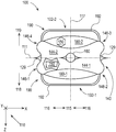
別の実施形態によると、容器は、可撓性材料を含み得る。可撓性材料は、第1の積層と第2の積層とを含み得る。第1の積層は、第1及び第2の封止可能な層の間に配設された第1の気体バリア層を含み得、第1及び第2の封止可能な層は、第1の積層の対向する外部層を画定する。第2の積層は、第2の積層の外部層を画定している第3の封止可能な層と、第2の気体バリア層とを含む。容器は、第3の封止可能な層の一部を第2の封止可能な層の少なくとも一部に結合させ、構造支持容積の少なくとも1つの境界部を確定する少なくとも1つの第1のシールを更に含む。構造支持容積は、第1及び第2の積層の間に配設される。容器は、可撓性材料の第1の領域内の第1の封止可能な層の一部を、可撓性材料の第2の領域内の第1の封止可能な層の一部に結合させる少なくとも1つの第2のシールを更に含み、この少なくとも1つの第2のシールは、構造支持容積の少なくとも1つの追加的な境界部を画定し、製品容積を少なくとも部分的に囲む。製品体積が、第1の領域内の第1の封止可能な層と第2の領域内の第1の封止可能な層との間に提供される。 According to another embodiment, the container may comprise a flexible material. The flexible material can include a first stack and a second stack. The first stack may include a first gas barrier layer disposed between the first and second sealable layers, the first and second sealable layers being the first Define opposing outer layers of the stack. The second stack includes a third sealable layer that defines an outer layer of the second stack and a second gas barrier layer. The container couples a portion of the third sealable layer to at least a portion of the second sealable layer and at least one first seal defining at least one boundary of the structural support volume. Is further included. The structural support volume is disposed between the first and second stacks. The container converts a portion of the first sealable layer in the first region of flexible material to a portion of the first sealable layer in the second region of flexible material. It further includes at least one second seal to be coupled, the at least one second seal defining at least one additional boundary of the structural support volume and at least partially surrounding the product volume. A product volume is provided between the first sealable layer in the first region and the first sealable layer in the second region.
本開示は、可撓性材料から作られる容器の種々の実施形態を記載する。これら容器は、可撓性材料から作られるために、これら容器は、従来の剛性容器と比較するとき、より安価で製造でき、より少ない材料を使用することが可能であり、装飾を施すことがより容易であり得る。第1に、可撓性材料(シート形態から完成品に至るまで)の変換は、一般的に、剛性材料(バルク形態から完成品に至るまで)の成形よりも、少ないエネルギー及び複雑性を必要とするために、これら容器は、安価で製造することができる。第2に、これら容器は、従来の剛性容器で使用された厚い固体壁の使用を必要としない新規な支持構造で構成されるために、これら容器はより少ない材料を使用することが可能である。第3に、可撓性材料が容器に形成される前に、これらが容易に印刷され得るために、これら可撓性容器は、装飾することがより容易であり得る。第4に、可撓性材料は、表面及び物体と接触する場合、それらの外部表面を変形させ、その後跳ね返らせるために、これら可撓性容器は、すり減りにくく、凹みにくく、並びに破裂しにくくなり得る。第5に、これら可撓性容器内の流動製品は、可撓性容器の側面がヒトの手でより容易にかつ制御可能に締めつけることができるために、より容易かつ慎重に分配され得る。 The present disclosure describes various embodiments of containers made from flexible materials. Because these containers are made from flexible materials, they can be manufactured cheaper, use less material and can be decorated when compared to conventional rigid containers. It can be easier. First, the transformation of flexible materials (from sheet form to finished product) generally requires less energy and complexity than molding rigid materials (from bulk form to finished product) Therefore, these containers can be manufactured at low cost. Second, because these containers are constructed with a novel support structure that does not require the use of the thick solid walls used in conventional rigid containers, they can use less material. . Third, the flexible containers can be easier to decorate because they can be easily printed before the flexible material is formed into the containers. Fourth, flexible materials are difficult to wear, dent, and rupture because flexible materials deform their outer surfaces when in contact with surfaces and objects, and then bounce off. Can be. Fifth, fluid products in these flexible containers can be more easily and carefully dispensed because the sides of the flexible containers can be tightened more easily and controllable with human hands.
本開示の容器は可撓性材料から作られているとはいえ、これらが破損することなく、意図された通りに、流動製品(複数可)を受容し、収容し、かつ分配することができるように、これら容器は十分な構造的一体性で構成され得る。更に、これら容器は、破損なく、意図されたように、これらがハンドリングからの外部力及び環境条件に耐え得るように、十分な構造的一体性で構成され得る。更に、これら容器は、破損なく、意図されたように、これらが展示されかつ実際に使用されることを可能にする構造で構成され得る。 Although the containers of the present disclosure are made from flexible materials, they can receive, contain, and dispense the fluid product (s) as intended without breaking. As such, these containers can be constructed with sufficient structural integrity. Furthermore, the containers can be constructed with sufficient structural integrity so that they can withstand external forces and environmental conditions from handling, as intended, without breakage. Furthermore, the containers can be constructed with a structure that allows them to be displayed and actually used as intended without breakage.
本明細書で使用するとき、用語「約」は、20パーセントをプラス又はマイナスした(+/−20%)特定の値と等しい範囲を指すことにより、特定の値を修飾する。本明細書で開示されている可撓性容器の実施形態のいずれかについて、特定の値の任意の開示もまた、種々の代替実施形態において、ほぼこの特定の値(すなわち、+/−20%)に等しい範囲の開示として理解され得る。 As used herein, the term “about” modifies a particular value by referring to a range equal to the particular value plus or minus 20 percent (+/− 20%). For any of the flexible container embodiments disclosed herein, any disclosure of a particular value is also approximately the same value (ie +/− 20%) in various alternative embodiments. ) Can be understood as disclosure of a range equal to.
本明細書で使用するとき、用語「周囲条件」とは、摂氏15〜35度の範囲内の温度及び35〜75%の範囲内の相対湿度を指す。 As used herein, the term “ambient conditions” refers to temperatures in the range of 15 to 35 degrees Celsius and relative humidity in the range of 35 to 75%.
本明細書で使用するとき、用語「およそ」は、15パーセントをプラス又はマイナスした(+/−15%)特定の値と等しい範囲を指すことにより、特定の値を修飾する。本明細書で開示されている可撓性容器の実施形態のいずれかについて、特定の値の任意の開示もまた、種々の代替実施形態において、およそこの特定の値(すなわち、+/−15%)に等しい範囲の開示として理解され得る。 As used herein, the term “approximately” modifies a particular value by referring to a range equal to the particular value plus or minus 15 percent (+/− 15%). For any of the flexible container embodiments disclosed herein, any disclosure of a particular value is also approximately the same value (ie, +/− 15%) in various alternative embodiments. ) Can be understood as disclosure of a range equal to.
本明細書で使用するとき、材料のシートを参照する際の、用語「坪量」とは、グラム/平方メートル(gsm)の単位での面積当たりの質量の度量を指す。本明細書で開示されている可撓性容器の実施形態のいずれかについて、種々の実施形態において、可撓性材料のいずれかは、10〜1000gsm、又は10〜1000のgsmについての任意の整数値、若しくは、例えば20〜800gsm、30〜600gsm、40〜400gsm、又は50〜200gsm等の、これら値のいずれかによって形成される任意の範囲の坪量を有するように構成され得る。 As used herein, the term “basis weight” when referring to a sheet of material refers to a measure of mass per area in units of grams per square meter (gsm). For any of the flexible container embodiments disclosed herein, in various embodiments, any of the flexible materials can be 10 to 1000 gsm, or any adjustment for 10 to 1000 gsm. It may be configured to have a numerical value or any range of basis weights formed by any of these values, such as 20-800 gsm, 30-600 gsm, 40-400 gsm, or 50-200 gsm.
本明細書で使用するとき、「バイオ含有量」とは、ASTM D6866−10、方法Bで決定されるように、材料内の合計有機炭素の質量の百分率としての、材料内の再生可能資源からの炭素の量を指し、かかる炭酸カルシウム等の無機資源からの炭素は、材料のバイオベースの含有量の決定において含まれない。種々の実施形態において、バイオ含有量を含む材料は、例えば、参照により本明細書に組み込まれる、公開された米国特許出願第2012288693号で記載されるような可撓性材料としての使用に好適であり得る。 As used herein, “bio content” refers to the renewable resources in a material as a percentage of the total organic carbon mass in the material as determined by ASTM D6866-10, Method B. Carbon from inorganic resources such as calcium carbonate is not included in determining the biobased content of the material. In various embodiments, the material containing biocontent is suitable for use as a flexible material, for example, as described in published US Patent Application No. 2012288893, incorporated herein by reference. possible.
本明細書で使用するとき、可撓性容器を参照する際の、用語「底部」とは、容器の全体高さの最下方30%、すなわち容器の全体高さの0〜30%に位置する容器の部分を指す。本明細書で使用するとき、用語「底部」は、用語「底部」を30%未満である特定の百分率値で修飾することにより更に限定され得る。本明細書で開示されている可撓性容器の実施形態のいずれかについては、容器の底部への参照は、種々の代替実施形態において、底部25%(すなわち、全体高さの0〜25%)、底部20%(すなわち、全体高さの0〜20%)、底部15%(すなわち、全体高さの0〜15%)、底部10%(すなわち、全体高さの0〜10%)、又は底部5%(すなわち、全体高さの0〜5%)、若しくは0%と30%の間の百分率の任意の整数値を指す。 As used herein, the term “bottom” when referring to a flexible container is located at the lowest 30% of the total height of the container, ie, 0-30% of the total height of the container. Refers to the container part. As used herein, the term “bottom” can be further limited by modifying the term “bottom” with a specific percentage value that is less than 30%. For any of the flexible container embodiments disclosed herein, reference to the bottom of the container refers to the bottom 25% (ie, 0-25% of the total height) in various alternative embodiments. ), Bottom 20% (ie 0-20% of the overall height), bottom 15% (ie 0-15% of the overall height), bottom 10% (ie 0-10% of the overall height), Or the bottom 5% (ie 0-5% of the total height) or any integer value between 0% and 30% percentage.
本明細書で使用するとき、用語「ブランド名」とは、製品を他の製品と識別するよう意図された視覚的要素を指す。ブランド名の例としては、以下:商標、トレードドレス、ロゴ、アイコン等のいずれか1つ以上が挙げられる。本明細書で開示されている可撓性容器の実施形態のいずれかについては、種々の実施形態において、可撓性容器のいかなる表面も、本明細書で開示されている又は当該技術分野において既知の任意の寸法、形状、又は構成の1つ以上のブランド名を任意の組み合わせで含み得る。 As used herein, the term “brand name” refers to a visual element that is intended to distinguish a product from other products. Examples of brand names include any one or more of the following: trademarks, trade dresses, logos, icons, and the like. For any of the flexible container embodiments disclosed herein, in various embodiments, any surface of the flexible container is disclosed herein or known in the art. One or more brand names of any size, shape, or configuration may be included in any combination.
本明細書で使用するとき、用語「文字」とは、情報を伝達するよう意図された視覚的要素を指す。文字の例としては、以下:アルファベット、数字、記号等のいずれか1つ以上が挙げられる。本明細書で開示されている可撓性容器の実施形態のいずれかについて、種々の実施形態において、可撓性容器のいかなる表面も、本明細書で開示されている又は当該技術分野において既知の任意の寸法、形状、又は構成の1つ以上の文字を、任意の組み合わせで含み得る。 As used herein, the term “character” refers to a visual element intended to convey information. Examples of characters include one or more of the following: alphabets, numbers, symbols, and the like. For any of the embodiments of the flexible container disclosed herein, in various embodiments, any surface of the flexible container is disclosed herein or known in the art. One or more characters of any size, shape, or configuration may be included in any combination.
本明細書で使用するとき、用語「密封された」とは、製品容積内の流動製品が、製品容積から漏れることが防止されるが、製品容積が必ずしも気密封止されるものではない、製品容積の状態を指す。例えば、密封容器は、容器内の上部空間が容器の外側の環境内の空気と流体連通することを可能にする通気栓を含み得る。 As used herein, the term “sealed” refers to a product that prevents fluid product within the product volume from leaking out of the product volume, but the product volume is not necessarily hermetically sealed. Refers to the volume state. For example, the sealed container may include a vent plug that allows the upper space within the container to be in fluid communication with air in the environment outside the container.
本明細書で使用するとき、用語「直接接続される」とは、取り付けの任意の手段(例えば、接着剤)以外で、要素が、それらの間にいかなる中間要素もなく互いに取り付けられている構成を指す。 As used herein, the term “directly connected” refers to a configuration in which elements are attached to each other without any intermediate elements between them, except for any means of attachment (eg, adhesive). Point to.
本明細書で使用するとき、可撓性容器を参照する際の、用語「ディスペンサー」とは、製品容積から及び/又は混合容積から流動製品(複数可)を容器の外側の環境に分配するように構成された構造を指す。本明細書で開示されている可撓性容器の実施形態のいずれかについて、いかなるディスペンサーも、任意の好適な寸法、形状、及び流速を含める本明細書で開示されている又は当該技術分野において既知の任意の方法で構成され得る。例えば、ディスペンサーは、プッシュプル式ディスペンサー、フリップトップキャップを備えたディスペンサー、ねじ留め式キャップを備えたディスペンサー、回転式ディスペンサー、キャップを備えたディスペンサー、ポンプ式ディスペンサー、ポンプ噴霧式ディスペンサー、トリガー噴霧式ディスペンサー、ストローディスペンサー、フリップアップストローディスペンサー、喰い込み式弁を備えたストローディスペンサー、配量ディスペンサー等であり得る。ディスペンサーは、複数の製品容積と流体連通する複数の流路をもたらす並列ディスペンサーであり得、これら流路は、分配の時点まで別のままで残り、これによって、複数の製品容積からの流動製品が、同時に一緒に分配される分離する流動製品として分配されることを可能にする。ディスペンサーは、複数の流路が分配の時点より前に合併され、これによって、複数の製品体積からの流動製品が一緒に混合された流動製品として分配されることを可能にする、複数の製品体積と流体連通する1つ以上の流路をもたらす混合ディスペンサーであり得る。別の例として、ディスペンサーは、脆い開口部から形成され得る。他の例として、ディスペンサーは、「One−way valve for inflatable package」と題された、公開された米国特許出願第2003/0096068号;「Self−sealing container」と題された米国特許第4,988,016号、及び「Pacakage having a fluid actuated closure」と題された米国特許第7,207,717号(このそれぞれが、参照により本明細書に組み込まれている)で開示されているものなど、当該技術分野において開示された1つ以上の弁及び/又は分配機構を利用することができる。なお更に、本明細書に開示されているディスペンサーのいずれも、直接的に、又は1つ以上の他の材料又は構造(嵌合具など)との組み合わせのいずれかで、若しくは当該技術分野において既知の任意の方法で、可撓性容器に組み込まれ得る。いくつかの代替実施形態において、本明細書で開示されるディスペンサーは、1つ以上のディスペンサーを通して製品容積(複数可)の充填を可能にするために、分配用及び充填用の双方に構成され得る。他の代替実施形態において、製品容積は、1つ以上のディスペンサー(複数可)に加えて又はこれらの代わりに、1つ以上の充填構造(複数可)(例えば、水を混合容積に付加するための)を含むことができる。あるいは、本明細書に開示されているディスペンサーに用いるいかなる場所も、充填構造の場所としても使用され得る。 As used herein, when referring to a flexible container, the term “dispenser” refers to dispensing fluid product (s) from the product volume and / or from the mixing volume to the environment outside the container. Refers to the structure constructed in For any of the flexible container embodiments disclosed herein, any dispenser is disclosed herein or known in the art, including any suitable dimensions, shapes, and flow rates. It can be configured in any way. For example, dispensers include push-pull dispensers, dispensers with flip top caps, dispensers with screw caps, rotary dispensers, dispensers with caps, pump dispensers, pump spray dispensers, trigger spray dispensers A straw dispenser, a flip-up straw dispenser, a straw dispenser with a bite-in valve, a dispensing dispenser and the like. The dispenser can be a parallel dispenser that provides multiple flow paths in fluid communication with multiple product volumes that remain separate until the time of dispensing, thereby allowing flow products from multiple product volumes to flow. , Allowing them to be distributed as separate fluid products that are distributed together at the same time. The dispenser has multiple product volumes where multiple flow paths are merged prior to the time of dispensing, thereby allowing fluid products from multiple product volumes to be dispensed together as a fluid product mixed together It may be a mixing dispenser that provides one or more flow paths in fluid communication with. As another example, the dispenser can be formed from a fragile opening. As another example, a dispenser is disclosed in published US patent application 2003/0096068 entitled “One-way valve for inflatable package”; US Pat. No. 4,988 entitled “Self-sealing container”. , 016, and U.S. Pat. No. 7,207,717 entitled “Pakakage having a fluid actuated closure,” each of which is incorporated herein by reference, etc. One or more valves and / or dispensing mechanisms disclosed in the art can be utilized. Still further, any of the dispensers disclosed herein are either directly or in combination with one or more other materials or structures (such as fittings) or known in the art. Can be incorporated into the flexible container in any of the following ways. In some alternative embodiments, the dispensers disclosed herein can be configured for both dispensing and filling to allow filling of the product volume (s) through one or more dispensers. . In other alternative embodiments, the product volume is in addition to or in place of one or more dispenser (s) one or more filling structure (s) (eg to add water to the mixing volume). Of) can be included. Alternatively, any location used for the dispenser disclosed herein can be used as the location of the filling structure.
本明細書で使用するとき、可撓性容器を参照する際の、用語「使い捨て」とは、エンドユーザに製品を分配後に、製品の追加量で再充填するように構成されておらず、廃棄されるように構成されている(すなわち、廃棄物、堆肥、及び/又はリサイクル材料として)容器を指す。本明細書に開示されている可撓性容器の実施形態のいずれかの部品、パーツ、又は全ては、使い捨てであるように構成され得る。 As used herein, the term “disposable” when referring to a flexible container is not configured to be refilled with an additional amount of product after dispensing the product to the end user and discarded. Refers to a container that is configured to be (ie, as waste, compost, and / or recycled material). Any part, part, or all of the flexible container embodiments disclosed herein may be configured to be disposable.
本明細書で使用するとき、可撓性容器を参照する際の、用語「耐久性のある」とは、非耐久性の容器を超えて再利用可能である容器を指す。 As used herein, the term “durable” when referring to a flexible container refers to a container that is reusable beyond a non-durable container.
本明細書で使用するとき、可撓性容器を参照する際の、用語「有効底接触面積」とは、容器(その製品容積(複数可)の全てが水で100%充填された状態で)が直立していて、その底部が水平支持面上に静止している場合の、その容器の底部の一部により画定される特定の面積を指す。この有効底接触面積は、水平支持面によって画定される平面内にある。この有効底接触面積は、全ての側面上の外側周辺部によって囲まれている連続する面積である。 As used herein, the term “effective bottom contact area” when referring to a flexible container refers to the container (with all of its product volume (s) 100% filled with water). Refers to the specific area defined by a portion of the bottom of the container when it is upright and its bottom rests on a horizontal support surface. This effective bottom contact area is in the plane defined by the horizontal support surface. This effective bottom contact area is a continuous area surrounded by the outer perimeter on all sides.
外側周辺部は、実際の接触面積から並びに容器の底部で取られた定義された断面からの一連の投影面積から形成される。有効底接触面積が画定されるとき、実際の接触面積は、水平支持面と接触する容器の底部の1つ以上の部分である。有効底接触面積は、実際の接触面積の全てを包含する。しかしながら、一部の実施形態では、有効底接触面積は、実際の接触面積を越えて広がってもよい。 The outer perimeter is formed from the actual contact area as well as from a series of projected areas from a defined cross section taken at the bottom of the container. When the effective bottom contact area is defined, the actual contact area is one or more portions of the bottom of the container that contact the horizontal support surface. The effective bottom contact area includes all of the actual contact area. However, in some embodiments, the effective bottom contact area may extend beyond the actual contact area.
一連の投影面積は、可撓性容器の底部で取られた5つの水平断面から形成される。これら断面は、全体高さの1%、2%、3%、4%、及び5%で取られる。これら断面のそれぞれの外側の範囲が、水平支持面に対して垂直下向きに投影され、5つの(重複する)投影面積を形成し、これが実際の接触面積と一緒になり、単一の結合面積を形成する。この結合面積は、これら面積(投影面積及び実際の面積)の値の累計ではく、互いに重なり合うこれら面積(投影面積及び実際の面積)の全てを包含するの単一の結合面積のフォーメーションであり、いかなる重複部分も、単一の結合面積に一度寄与するにすぎない。 A series of projected areas is formed from five horizontal sections taken at the bottom of the flexible container. These sections are taken at 1%, 2%, 3%, 4% and 5% of the total height. The outer extent of each of these cross-sections is projected vertically downward with respect to the horizontal support surface to form five (overlapping) projected areas, which together with the actual contact area, create a single bonded area Form. This combined area is not a cumulative value of these areas (projected area and actual area), but a formation of a single combined area that encompasses all of these areas (projected area and actual area) that overlap each other, Any overlap only contributes once to a single bond area.
有効底接触面積の外側周辺部は、以下に記載する通りに形成される。以下の説明において、用語凸面、突出部、凹面、及び凹状部は、結合面積の外側のポイントの透視図から理解される。外側周辺部は、結合面積の外側範囲と以下に説明するように構成された直線セグメントである弦との組み合わせにより形成される。 The outer periphery of the effective bottom contact area is formed as described below. In the following description, the terms convex surface, protrusion, concave surface, and concave portion will be understood from a perspective view of points outside the bond area. The outer periphery is formed by the combination of the outer range of the coupling area and the strings that are linear segments configured as described below.
凹面又は凹状である形状を備える外側周辺部を有する結合面積のそれぞれの連続部分について、弦はこの部分にわたり構成される。この弦は、凹面/凹状部の両側の結合面積に対して引かれた接線であり得る最も短い直線セグメントである。 For each continuous portion of the bonded area having an outer periphery with a shape that is concave or concave, the string is constructed over this portion. This string is the shortest straight line segment that can be a tangent line drawn to the combined area on both sides of the concave / concave part.
(2つ又はそれ以上の分離した部分により形成された)不連続部である結合面積については、1つ以上の弦が、1つ以上の不連続部(これら部分間に配設された空きスペース)にわたって結合面積の外辺部の周りで構成される。これら弦は、結合面積の最も外側の分離する部分に対して接線を引かれた直線セグメントである。これら弦は、可能な限り最大の有効底接触面積を作り出すように引かれる。 For a combined area that is a discontinuity (formed by two or more separate portions), one or more strings are replaced by one or more discontinuities (an empty space disposed between these portions). ) Around the outer edge of the bond area. These chords are straight line segments that are tangent to the outermost separating portion of the bond area. These strings are drawn to create the largest possible bottom contact area possible.
したがって、外側周辺部は、結合面積の外側範囲及び上記のように構成された任意の弦との組み合わせにより形成され、これらすべてが一緒になり有効底面積を包囲する。結合面積及び/又は1つ以上のその他の弦によって囲まれている任意の弦は、外側周辺部の一部ではなく、無視されるべきである。 Thus, the outer perimeter is formed by a combination of the outer range of the coupling area and any chord configured as described above, all of which together enclose the effective bottom area. Any string that is surrounded by the bond area and / or one or more other strings should not be part of the outer perimeter and should be ignored.
本明細書に開示されている可撓性容器の実施形態のいずれも、1〜50,000平方センチメートル(cm2)、又は1と50,000cm2の間のcm2の任意の整数値、又は例えば、2〜25,000cm2、3〜10,000cm2、4〜5,000cm2、5〜2,500cm2、10〜1,000cm2、2〜500cm2、30〜300cm2、40〜200cm2、又は50〜100cm2等の前述の値のいずれかにより形成される任意の範囲内の有効底接触面積を有するように構成され得る。 Any of the embodiments of the flexible container disclosed herein, to 50,000 square centimeters (cm 2), or 1 and 50,000cm any integer value of cm 2 between the two, or for example , 2~25,000cm 2, 3~10,000cm 2, 4~5,000cm 2, 5~2,500cm 2, 10~1,000cm 2, 2~500cm 2, 30~300cm 2, 40~200cm 2 Or having an effective bottom contact area within any range formed by any of the aforementioned values, such as 50-100 cm 2 .
本明細書で使用するとき、可撓性容器を参照する際の、用語「膨張した」とは、1つ以上の膨張材料により構造支持容積が堅く作られた後に、構造支持容積を形成するように構成される1つ以上の可撓性材料の状態を指す。膨張した構造支持容積は、構造支持容積が1つ以上の膨張材料で充填される前に、1つ以上の膨張材料の組み合わされた厚さを大幅に超える全体幅を有する。膨張材料の例としては、液体(例えば、水)、気体(例えば、圧搾空気)、流動製品、発泡体(構造支持容積に付加された後に膨張することが可能である)、又は相転移材料(固体又は液体形態で付加されるが、気体に変化するもの、例えば、液体窒素又はドライアイス)、又は当該技術分野において既知の他の好適な材料、若しくはこれら(例えば、流動製品及び液体窒素)のいずれかの組み合わせが挙げられる。種々の実施形態において、膨張材料は、大気圧で付加され、又は大気圧を超える圧力下で付加され、若しくは、大気圧よりいくらか高い圧力まで圧力を増大させる材料変化をもたらすように付加され得る。本明細書に開示されている、可撓性容器の実施形態のいずれかについて、その1つ以上の可撓性材料は、例えば、その製品容積(複数可)が流動製品で充填される前後、及び可撓性容器が販売者に出荷される前後、並びに可撓性容器がエンドユーザにより購入される前後を含める、その製造、販売、及び使用に対して種々の時点で膨張され得る。 As used herein, when referring to a flexible container, the term “expanded” refers to forming a structural support volume after the structural support volume is made rigid by one or more inflatable materials. Refers to the state of one or more flexible materials configured in The expanded structural support volume has an overall width that significantly exceeds the combined thickness of the one or more expansion materials before the structural support volume is filled with the one or more expansion materials. Examples of intumescent materials include liquids (eg, water), gases (eg, compressed air), fluid products, foams (which can be expanded after being added to a structural support volume), or phase change materials ( Those added in solid or liquid form but converted to a gas, such as liquid nitrogen or dry ice), or other suitable materials known in the art, or such (eg, fluid products and liquid nitrogen) Any combination is mentioned. In various embodiments, the expansion material can be added at atmospheric pressure, added under pressure above atmospheric pressure, or added to effect a material change that increases the pressure to a pressure somewhat above atmospheric pressure. For any of the flexible container embodiments disclosed herein, the one or more flexible materials can be, for example, before and after the product volume (s) are filled with a fluidized product, And before and after the flexible container is shipped to the seller, and before and after the flexible container is purchased by the end user, it can be inflated at various times for its manufacture, sale and use.
本明細書で使用するとき、可撓性容器の製品容積を参照する際の、用語「充填される」とは、周囲条件下で、上部空間を許容した状態で、製品容積が、製品容積の全容積に等しい流動製品(複数可)の量を収容する場合の状態を指す。本明細書で使用するとき、用語「充填される」は、用語「特定の百分率値で充填される」を使用して修飾され得、ここでは、100%充填されるとは、製品容積の最大容積を表す。 As used herein, when referring to the product volume of a flexible container, the term “filled” means that the product volume is the product volume of the product volume, allowing for headspace under ambient conditions. Refers to the condition when containing an amount of fluid product (s) equal to the total volume. As used herein, the term “filled” may be modified using the term “filled with a certain percentage value” where 100% filled is the maximum of product volume Represents volume.
本明細書で使用するとき、用語「平坦な」とは、顕著な凹凸がない表面を指す。 As used herein, the term “flat” refers to a surface that is free of significant irregularities.
本明細書で使用するとき、用語「可撓性容器」とは、製品容積を有するように構成された容器を指し、ここでは1つ以上の可撓性材料が、製品容積の三次元空間を画定する1つ以上の材料の全体表面積の50〜100%を形成する。本明細書に開示されている可撓性容器の実施形態のいずれかについて、種々の実施形態では、可撓性容器は、製品容積を有するように構成され得、ここでは1つ以上の可撓性材料が、三次元空間を画定する1つ以上の材料の全体面積の特定の百分率を形成し、特定の百分率は、50%と100%の間の百分率についての任意の整数値であるか、若しくは、例えば60〜100%、又は70〜100%、又は80〜100%、又は90〜100%等のこれら値のいずれかにより形成される任意の範囲内である。可撓性容器の一種は、フィルム系容器であり、これはフィルムを含有する1つ以上の可撓性材料から作られる可撓性容器である。 As used herein, the term “flexible container” refers to a container that is configured to have a product volume, wherein one or more flexible materials are used to define a three-dimensional space in the product volume. Forms 50-100% of the total surface area of the one or more materials being defined. For any of the flexible container embodiments disclosed herein, in various embodiments, the flexible container can be configured to have a product volume, wherein one or more flexible containers are here. The sexual material forms a specific percentage of the total area of the one or more materials that define the three-dimensional space, the specific percentage being any integer value for the percentage between 50% and 100%; Or, for example, within any range formed by any of these values such as 60-100%, or 70-100%, or 80-100%, or 90-100%. One type of flexible container is a film-based container, which is a flexible container made from one or more flexible materials containing a film.
本明細書に開示されている可撓性容器の実施形態のいずれかについて、種々の実施形態では、可撓性容器の中間部(いずれの流動製品も除いた)は、全体の中間部質量を有するように構成され得、ここでは、1つ以上の可撓性材料が全体の中間部質量の特定の百分率を形成し、この特定の百分率は、50%と100%の間の百分率についての任意の整数値であるか、若しくは、例えば、60〜100%であるか、若しくは70〜100%、又は80〜100%、又は90〜100%等の前述の値のいずれかにより形成される任意の範囲内にある。 For any of the flexible container embodiments disclosed herein, in various embodiments, the intermediate portion of the flexible container (excluding any flow product) has an overall intermediate mass. Wherein the one or more flexible materials form a specific percentage of the total intermediate mass, this specific percentage being optional for a percentage between 50% and 100% Any integer formed by any of the aforementioned values, such as, for example, 60-100%, or 70-100%, or 80-100%, or 90-100% Is in range.
本明細書に開示されている可撓性容器の実施形態のいずれかについて、種々の実施形態で、全可撓性容器(いずれの流動製品も除いた)は、全体質量を有するように構成され、この中で、1つ以上の可撓性材料は、全体質量の特定の百分率を形成し、この特定の百分率は、50%と100%の間の百分率についての任意の整数値であるか、若しくは、例えば、60〜100%であるか、若しくは70〜100%、又は80〜100%、又は90〜100%等の前述の値のいずれかにより形成される任意の範囲内である。 For any of the flexible container embodiments disclosed herein, in various embodiments, the entire flexible container (excluding any flow product) is configured to have an overall mass. Wherein the one or more flexible materials form a specific percentage of the total mass, the specific percentage being any integer value for the percentage between 50% and 100%, Or, for example, 60-100%, or within any range formed by any of the aforementioned values such as 70-100%, or 80-100%, or 90-100%.
本明細書で使用するとき、可撓性容器を参照する際の、用語「可撓性材料」とは、1,000〜2,500,000N/mの範囲内のたわみ率を有する、薄い、容易に変形可能な、シート様材料を指す。本明細書に開示されている可撓性容器の実施形態のいずれかについて、種々の実施形態で、可撓性材料のいずれかは、1,000〜2,500,000N/mのたわみ率を有するよう、又は1,000〜2,500,000N/mのたわみ率についての任意の整数値を有するよう、若しくは、例えば、1,000〜1,500,000N/m、1,500〜1,000,000N/m、2,500〜800,000N/m、5,000〜700,000N/m、10,000〜600,000N/m、15,000〜500,000N/m、20,000〜400,000N/m、25,000〜300,000N/m、30,000〜200,000N/m、35,000〜100,000N/m、40,000〜90,000N/m、又は45,000〜85,000N/m等のこれらの値のいずれかにより形成される任意の範囲内のたわみ率を有するように構成され得る。本開示の全体を通して、用語「可撓性材料」、「可撓性シート」、「シート」、及び「シート様材料」は、互換的に用いられ、同一の意味を有するよう意図される。可撓性材料であり得る材料の例としては、以下のいずれかの1つ以上:本明細書に記載されている又は当該技術分野において既知の、微細層構造又はナノ層構造内の、並びに任意の組み合わせ内の、分離した材料(複数可)として、又は積層の層(複数可)として、組成物材料の部品(複数可)として任意の構成における、フィルム(プラスチックフィルムなど)、エラストマー、発泡シート、フォイル、布類(例えば、織布及び不織布)、バイオソース材料、及び紙類が挙げられる。種々の実施形態において、可撓性材料の一部、部分、又は全ては、当該技術分野において既知の任意の方法で、コーティングされ又は未コートであり得、処理され又は未処理であり得、加工され又は未加工であり得る。種々の実施形態において、可撓性材料の一部、部分、若しくは可撓性材料のおよそ全て、又はほぼ全て、又は実質的に全て、又はほとんど全て、又は全ては、持続可能な、バイオソースの、再利用された、再利用可能な、及び/又は生分解性の材料からなる。本明細書に記載されている可撓性材料の一部、部分、若しくは可撓性材料のおよそ全て、又はほぼ全て、又は実質的に全て、又はほとんど全て、又は全ては、部分的に又は完全に半透明、部分的に又は完全に透明、若しくは部分的に又は完全に不透明であり得る。本明細書に開示されている容器を製造するために使用される可撓性材料は、当該技術分野において既知の任意の方法で形成され得、例えば、熱封着(例えば、導電性封着、衝撃封着、超音波封着等)、溶接、クリンプ加工、結合、接着等、及びこれらのいずれかの組み合わせを含める当該技術分野において既知のいかなる種類の接合又は封着法を使用して結合され得る。 As used herein, the term “flexible material” when referring to a flexible container, is a thin, having a deflection rate in the range of 1,000 to 2,500,000 N / m. Refers to a sheet-like material that is easily deformable. For any of the embodiments of the flexible container disclosed herein, in various embodiments, any of the flexible materials has a deflection rate of 1,000 to 2,500,000 N / m. Or have any integer value for the deflection rate of 1,000 to 2,500,000 N / m, or, for example, 1,000 to 1,500,000 N / m, 1,500 to 1, 000,000 N / m, 2,500 to 800,000 N / m, 5,000 to 700,000 N / m, 10,000 to 600,000 N / m, 15,000 to 500,000 N / m, 20,000 to 400,000 N / m, 25,000-300,000 N / m, 30,000-200,000 N / m, 35,000-100,000 N / m, 40,000-90,000 N / m, It may be configured to have a deflection factor in any range formed by any of these values, such as 45,000~85,000N / m. Throughout this disclosure, the terms “flexible material”, “flexible sheet”, “sheet”, and “sheet-like material” are used interchangeably and are intended to have the same meaning. Examples of materials that can be flexible materials include any one or more of the following: within a micro-layer structure or nano-layer structure as described herein or known in the art, as well as any Films (such as plastic films), elastomers, foam sheets in any configuration as separate material (s), as laminated layer (s), as part (s) of composition material, in a combination of , Foils, fabrics (eg, woven and non-woven), biosource materials, and papers. In various embodiments, a portion, part, or all of the flexible material can be coated or uncoated, treated or untreated, processed in any manner known in the art. Or raw. In various embodiments, a portion, part, or nearly all, or substantially all, or substantially all, or almost all, or all of the flexible material is sustainable, biosourced Consisting of recycled, reusable and / or biodegradable materials. Part, part, or substantially all, or substantially all, or substantially all, or almost all, or all of the flexible material described herein may be partially or completely May be translucent, partially or completely transparent, or partially or completely opaque. The flexible material used to manufacture the containers disclosed herein can be formed by any method known in the art, such as heat sealing (eg, conductive sealing, Bonded using any type of joining or sealing methods known in the art including impact sealing, ultrasonic sealing, etc.), welding, crimping, bonding, bonding, etc., and any combination thereof. obtain.
本明細書で使用するとき、可撓性容器を参照する際の、用語「たわみ率」とは、薄い、容易に変形可能な、シート様材料に関する材料パラメータを指し、このパラメータは、ニュートン/メートルで測定され、たわみ率は、ヤング弾性率についての値(パスカルで測定される)と材料の全体厚さについての値(メートルで測定される)との積に等しい。 As used herein, the term “deflection” when referring to a flexible container refers to a material parameter for a thin, easily deformable, sheet-like material, which is Newton / meter. The deflection rate is equal to the product of the value for Young's modulus (measured in Pascals) and the value for the total thickness of the material (measured in meters).
本明細書で使用するとき、可撓性容器を参照する際の、用語「流動製品」とは、1つ以上の液体及び/又は注入可能な固体、並びにこれらの組み合わせを指す。流動製品の例としては、以下のいずれかの1つ以上:バイト、ビット、クリーム、チップ、チャンク、クラム、結晶、エマルジョン、フレーク、ゲル、細粒、顆粒、ゼリー、キブル、液体溶液、液体懸濁液、ローション、ナゲット、軟膏、粒子、粒状物、ペースト、小片、ピル、粉末、膏薬、破片、粉状物等(単独で又は任意の組み合わせで)が挙げられる。本開示の全体を通して、用語「粒状製品」及び「流動性製品」は、互換的に使用され、同一の意味を有するよう意図される。本明細書に開示されている製品容積のいずれも、本明細書に開示されている、又は当該技術分野において既知の任意の流動製品の1つ以上を、任意の組み合わせで包含するように構成され得る。 As used herein, the term “fluid product” when referring to a flexible container refers to one or more liquids and / or injectable solids, and combinations thereof. Examples of fluid products include one or more of the following: bite, bit, cream, chip, chunk, crumb, crystal, emulsion, flake, gel, fine granule, granule, jelly, kibble, liquid solution, liquid suspension Examples include suspensions, lotions, nuggets, ointments, particles, granules, pastes, small pieces, pills, powders, salves, fragments, powders, etc. (alone or in any combination). Throughout this disclosure, the terms “granular product” and “flowable product” are used interchangeably and are intended to have the same meaning. Any of the product volumes disclosed herein are configured to include any combination of any one or more of the fluid products disclosed herein or known in the art. obtain.
本明細書で使用するとき、可撓性容器を参照する際の、用語「形成された」とは、製品容積が、その画定された三次元形状を供与された後に、製品容積に形作られるように構成される1つ以上の材料の状態を指す。 As used herein, the term “formed” when referring to a flexible container is such that the product volume is formed into a product volume after being provided with its defined three-dimensional shape. Refers to the state of one or more materials constructed.
本明細書で使用するとき、用語「気体バリア層」とは、可撓性材料の積層の層を指し、気体バリア層は、層を通る気体の透過に抵抗する材料又はコーティングされた材料である。気体バリア層は、可撓性材料を通る気体の透過に対して少なくとも部分的な抵抗を付与する。可撓性材料は、1つ以上の気体バリア層を含有することができる。気体バリア層は、例えば、約0.1cc/m2日・MPa〜約98716.7cc/m2日・MPa(約0.01cc/m2・日・気圧〜約10,000cc/m2・日・気圧)、約0.1cc/m2日・MPa〜約29615cc/m2日・MPa(約0.01cc/m2・日・気圧〜約3000cc/m2・日・気圧)、約0.1cc/m2日・MPa〜約197.4cc/m2日・MPa(約0.01cc/m2・日・気圧〜約20cc/m2・日・気圧)、約0.49cc/m2m2日・MPa〜約177.7cc/m2日・MPa(約0.05cc/m2・日・気圧〜約18cc/m2・日・気圧)、約0.49cc/m2日・MPa〜約29.6cc/m2日・MPa(約0.05cc/m2・日・気圧〜約3cc/m2・日・気圧)、約0.49cc/m2日・MPa〜約9.9cc/m2日・MPa(約0.05cc/m2・日・気圧〜約1cc/m2・日・気圧)、 約246.8cc/m2日・MPa〜約987.2cc/m2日・MPa(約25cc/m2・日・気圧〜約100cc/m2・日・気圧)、約493.6cc/m2日・MPa〜約4935.8cc/m2日・MPa(約50cc/m2・日・気圧〜約500cc/m2・日・気圧)、約9871.7cc/m2日・MPa〜約49358.3cc/m2日・MPa(約1000cc/m2・日・気圧〜約5000cc/m2・日・気圧)、約49358.3cc/m2日・MPa〜約98716.7cc/m2日・MPa(約5000cc/m2・日・気圧〜約10,000 cc/m2・日・気圧)の気体透過速度を有し得る。他の好適な気体透過速度としては、例えば、約0.01、0.49、1、4.9、9.9、49.3、98.7、148.1、197.4、246.8、296.2、345.5、394.9、444.2、493.6、740.4、987.2、1480.8、1974.3、2467.9、 2961.5 、3455.1、3948.7、4442.3、4935.8、5923、6910.2、7897.3 、8884.5、9871.7、 19743.3、29615、39486.7、49358.3、59230、69101.7、78973.3、88845、98716.7cc/m2日・MPa(約0.01、0.05.0.1、0.5、1、5、10、15、20、25、30、35、40、45、50、75、100、150、200、250、300、350、400、450、500、600、700、800、900、1000、2000、3000、4000、5000、6000、7000、8000、9000、及び10000cc/m2・日・気圧)、並びにこれら値の組み合わせにより形成される任意の範囲が挙げられる。例えば、気体バリア層は、窒素に対する前述の気体透過速度を有し得る。特記されない限り、気体透過速度は、高圧側の高純度試験気体の0.1MPa(1気圧)の分圧及び低圧側の清浄な大気の0.1MPa(1気圧)の分圧で、手順Vを使用して、50%の相対湿度及び25℃にてASTM D 1434−82により測定される。 As used herein, the term “gas barrier layer” refers to a layer of a stack of flexible materials, which is a material or coated material that resists the permeation of gas through the layer. . The gas barrier layer provides at least partial resistance to gas permeation through the flexible material. The flexible material can contain one or more gas barrier layers. The gas barrier layer is, for example, about 0.1 cc / m 2 day · MPa to about 98716.7 cc / m 2 day · MPa (about 0.01 cc / m 2 · day · atmospheric pressure to about 10,000 cc / m 2 · day.・ Atmospheric pressure), about 0.1 cc / m 2 day · MPa to about 29615 cc / m 2 day · MPa (about 0.01 cc / m 2 · day · atmospheric pressure to about 3000 cc / m 2 · day · atmospheric pressure), about 0. 1cc / m 2 day · MPa~ about 197.4cc / m 2 day · MPa (about 0.01cc / m 2 · day, atmospheric pressure to about 20cc / m 2 · day, atmospheric pressure), about 0.49cc / m2m 2 days・ MPa to about 177.7 cc / m 2 day · MPa (about 0.05 cc / m 2 · day · atmospheric pressure to about 18 cc / m 2 · day · atmospheric pressure), about 0.49 cc / m 2 day · MPa to about 29 .6 cc / m 2 day · MPa (about 0.05 cc / m 2 · day · atmosphere to about 3 cc / m 2 · day · atmosphere), about 0. 49cc / m 2 days · MPa~ about 9.9cc / m 2 day · MPa (about 0.05cc / m 2 · day, atmospheric pressure to about 1cc / m 2 · day, atmospheric pressure), about 246.8cc / m 2 days · MPa to about 987.2 cc / m 2 days · MPa (about 25 cc / m 2 · day · atmosphere to about 100 cc / m 2 · day · atmosphere), about 493.6 cc / m 2 days · MPa to about 4935.8 cc / m 2 day · MPa (about 50cc / m 2 · day, atmospheric pressure to about 500cc / m 2 · day, atmospheric pressure), about 9871.7cc / m 2 days · MPa~ about 49358.3cc / m 2 day · MPa ( about 1000cc / m 2 · day, atmospheric pressure to about 5000cc / m 2 · day, atmospheric pressure), about 49358.3cc / m 2 days · MPa~ about 98716.7cc / m 2 day · MPa (about 5000cc / m 2 · day - pressure to about 10,000 cc / m has a gas transmission rate of 2 · day · pressure) That. Other suitable gas permeation rates include, for example, about 0.01, 0.49, 1, 4.9, 9.9, 49.3, 98.7, 148.1, 197.4, 246.8. 296.2, 345.5, 394.9, 444.2, 493.6, 740.4, 987.2, 1480.8, 1974.3, 2467.9, 2961.5, 3455.1, 3948 , 4442.3, 4935.8, 5923, 6910.2, 7897.3, 8884.5, 9871.7, 19743.3, 29615, 39486.7, 49358.3, 59230, 69101.7, 78973 .3, 88845, 98716.7 cc / m 2 day.MPa (about 0.01, 0.05.0.1, 0.5, 1 , 5, 10, 15, 20 , 25, 30, 35, 40, 45, 50, 75, 100 150,200,250,300,350,400,450,500,600,700,800,900,1000,2000,3000,4000,5000,6000,7000,8000,9000, and 10000cc / m 2 · day, Pressure), as well as any range formed by a combination of these values. For example, the gas barrier layer can have the aforementioned gas transmission rate for nitrogen. Unless otherwise noted, the gas permeation rate is determined by the procedure V at a partial pressure of 0.1 MPa (1 atm) for the high purity test gas on the high pressure side and a partial pressure of 0.1 MPa (1 atm) for the clean atmosphere on the low pressure side. In use, measured by ASTM D 1434-82 at 50% relative humidity and 25 ° C.
代表的な気体バリア層は、エチレンビニルアルコールである。EVOHの気体透過速度は、層の厚さ及び層内のエチレン含有量のモル%を変更することにより調整され得る。エチレンのより低い含有量がより低い気体透過速度を有する気体バリア層を結果として生じる状態で、EVOH気体バリア層は、約24モル%〜約48モル%のエチレンを含有し得る。更に、気体バリア層の気体透過速度は、より厚い層をもたらすことにより低減され得る。例えば、EVOHの気体バリア層の気体透過速度は、バリア材料中のエチレンのモル%及び/又は気体バリア層の厚さを変更することにより調整され得る。広くは、EVOHのモル%が増加すると、気体透過速度が増加し、同時に気体バリア層の厚さが増加すると、ガス透過速度を減少する。例えば、約0.49cc/m2日・MPa(約0.05cc/m2・日・気圧)の窒素に対する気体透過速度を有する可撓性材料は、32モル%のエチレンを有するEVOHから形成された気体バリア層を含み得及び/又はこの気体バリア層は約9マイクロメートル以上の厚さを有し得る。例えば、約177.7cc/m2日・MPa(約18cc/m2・日・気圧)などの窒素に対する増大した気体透過速度を有する可撓性材料では、エチレン含有量は、32モル%を超えるまで増加され及び/又は約9マイクロメートル未満の厚さにされ得る。その他の好適な気体バリア層材料としては、例えば、ナイロン、ポリアミド、ナイロン6、ポリアミド6、ナイロンMXD6、PVOH、PVC、PVDC、PCTFE、ゾル−ゲル材料、液晶ポリマー、コーティングされた基材、PAN3、配向されたPA6、PGA、PHA、PLA、セルロース系エステル、TPS、PBS、真空で金属又は金属酸化物がコーティングされた可撓性材料(例えば、Al、SiOx、AlOx)、ナノクレイがコーティングされた可撓性材料、フォイル、並びにこれらの配合物、組合せ物、積層、微細層、ナノ層、及び共押出成形品を挙げることができる。これら材料は、バイオベース材料、石油系材料及び/又は再生材料又は粉砕再生材料であり得る。 A typical gas barrier layer is ethylene vinyl alcohol. The gas permeation rate of EVOH can be adjusted by changing the layer thickness and the mole percent of the ethylene content in the layer. The EVOH gas barrier layer may contain from about 24 mole percent to about 48 mole percent ethylene, with a lower content of ethylene resulting in a gas barrier layer having a lower gas transmission rate. Furthermore, the gas permeation rate of the gas barrier layer can be reduced by providing a thicker layer. For example, the gas permeation rate of the EVOH gas barrier layer can be adjusted by changing the mole percent of ethylene in the barrier material and / or the thickness of the gas barrier layer. In general, increasing the mole percent of EVOH increases the gas permeation rate, while simultaneously decreasing the gas barrier layer thickness decreases the gas permeation rate. For example, a flexible material having a gas permeation rate for nitrogen of about 0.49 cc / m 2 day · MPa (about 0.05 cc / m 2 · day · atmosphere) is formed from EVOH with 32 mole% ethylene. And / or the gas barrier layer may have a thickness of about 9 micrometers or greater. For example, in a flexible material having an increased gas permeation rate for nitrogen, such as about 177.7 cc / m 2 day · MPa (about 18 cc / m 2 · day · atmospheric pressure), the ethylene content exceeds 32 mol%. And / or a thickness of less than about 9 micrometers. Other suitable gas barrier layer materials include, for example, nylon, polyamide, nylon 6, polyamide 6, nylon MXD6, PVOH, PVC, PVDC, PCTFE, sol-gel materials, liquid crystal polymers, coated substrates, PAN3, Oriented PA6, PGA, PHA, PLA, cellulosic ester, TPS, PBS, flexible material coated with metal or metal oxide in vacuum (eg Al, SiOx, AlOx), nanoclay coated Mention may be made of flexible materials, foils, and their blends, combinations, laminates, microlayers, nanolayers, and coextrusions. These materials can be bio-based materials, petroleum-based materials and / or recycled materials or ground recycled materials.
本明細書で使用するとき、用語「図」とは、装飾を提供し、又は情報を発信するよう意図された視覚的要素を指す。図の例としては、以下のいずれかの1つ以上:色、パターン、デザイン、画像等が挙げられる。本明細書で開示されている可撓性容器の実施形態のいずれかについて、種々の実施形態では、可撓性容器のいかなる表面も、任意の組み合わせで、本明細書に開示されている又は当該技術分野において既知の任意の寸法、形状、又は構成の1つ以上の図を含み得る。 As used herein, the term “figure” refers to a visual element that is intended to provide decoration or to transmit information. Examples of diagrams include one or more of any of the following: color, pattern, design, image, etc. For any of the embodiments of the flexible container disclosed herein, in various embodiments, any surface of the flexible container is disclosed herein or in any combination It may include one or more views of any size, shape, or configuration known in the art.
本明細書で使用するとき、可撓性容器を参照する際の、用語「高さ面積比」とは、センチメートル当たりの単位(cm-1)を用いる容器に対する比を指し、これは容器の有効底接触面積(その製品容積の全てが水で100%充填された状態で、並びに有効底接触面積が平方センチメートルで測定されて)で割られた容器の全体高さについての値(その製品容積の全てが水で100%充填された状態で、並びに全体高さがセンチメートルで測定されて)に等しい。本明細書で開示されている可撓性容器の実施形態のいずれかについて、種々の実施形態では、可撓性容器のいずれも、0.3〜3.0/cmの高さ面積比、又は、例えば、0.3と3.0/センチメートルの間の0.05cm-1の増大幅での任意の値、若しくは、例えば0.35〜2.0cm-1、0.4〜1.5cm-1、0.4〜1.2cm-1、又は0.450.9〜cm-1等の前述の値のいずれかにより形成される任意の範囲内の値の高さ面積比を有するように構成され得る。
As used herein, the term “height area ratio” when referring to a flexible container refers to the ratio of the container to the unit using units per centimeter (cm −1 ), Value for the total height of the container divided by the effective bottom contact area (with all of its
本明細書で使用するとき、用語「表示部」とは、任意の組み合わせでの、文字、図、ブランド名、又はその他の視覚的要素の1つ以上を指す。本明細書で開示されている可撓性容器の実施形態のいずれかについて、種々の実施形態では、可撓性容器の表面のいずれも、任意の組み合わせで、本明細書に開示されている又は当該技術分野において既知の任意の寸法、形状、又は構成の1つ以上の表示部を含み得る。 As used herein, the term “indicator” refers to one or more of letters, diagrams, brand names, or other visual elements, in any combination. For any of the embodiments of the flexible container disclosed herein, in various embodiments, any of the surfaces of the flexible container are disclosed herein in any combination, or It can include one or more displays of any size, shape, or configuration known in the art.
本明細書で使用するとき、用語「間接的に接続した」とは、要素が、それらの間の1つ以上の中間要素を用いて互いに取り付けられている構成を指す。 As used herein, the term “indirectly connected” refers to a configuration in which elements are attached to each other using one or more intermediate elements therebetween.
本明細書で使用するとき、用語「結合した」とは、要素が直接的に接続されているか又は間接的に接続されているかのいずれかの構成を指す。 As used herein, the term “coupled” refers to a configuration in which elements are either directly connected or indirectly connected.
本明細書で使用するとき、用語「積層強度」とは、積層の隣接する層間の結合する接続の強度を指す。本開示よる積層は、約2N/m〜約10,000N/m、約4N/m〜約9000N/m、約17N/m〜約3150N/m、及び約34N/m〜約2450N/mの積層の各層の間の積層強度を有し得る。他の好適な積層強度として、約2、3、4、5、6、7、8、9、10、11、12、13、14、15、16、17、18、19、20、25、30、35、40、45、50、55、60、65、70、75、80、85、90、95、100、125、150、175、200、225、250、275、300、350、400、450、500、550、600、650、700、750、800、850、900、1000、1250、1500、2000、2500、3000、3500、4000、4500、5000、5500、6000、6500、7000、7500、8000、8500、9000、及び10000N/m、並びにこれら値の組み合わせにより形成される任意の範囲が挙げられる。特記されない限り、本明細書に開示される積層強度は、280mm/分の延伸速度を用いて、並びに破壊されたままの試料の未分離部分を自由に移動させる状態で、ASTM F 904−98により測定される。積層強度は、結合層及び接着剤の使用を含める直接接触で層を選択することにより調整され得る。例えば、上記記載の範囲よりも低い積層強度を有する積層が、所定の用途に好適である場合、積層は、結合層なしに及び/又は積層の層の一部又はその全ての間の結合層と共に及び/又は約1マイクロメートル以下の非常に薄い結合層と共に形成され得る。s高い積層強度は、化学的に類似した又は共反応性を有する層を直接的に接続することにより達成され得る。例えば、ナイロン及びEVOHは、強い反応性を有し、一般的に共押出され、追加された結合層又は接着剤層の必要なしに高い積層強度を生み出すことができる。ポリエチレン層は、他のポリエチレン含有層と化学的類似性を有し、いくつかの実施形態では、これらは、結合層又は接着剤層の必要なく直接的に接続され、十分な積層強度(すなわち、2N/m〜10,000N/mno範囲の)をもたらすことができる。 As used herein, the term “laminate strength” refers to the strength of a bonded connection between adjacent layers of a laminate. Laminates according to the present disclosure can be from about 2 N / m to about 10,000 N / m, from about 4 N / m to about 9000 N / m, from about 17 N / m to about 3150 N / m, and from about 34 N / m to about 2450 N / m The laminate strength between each of the layers may be. Other suitable laminate strengths are about 2, 3, 4, 5, 6, 7, 8, 9, 10, 11, 12, 13, 14, 15, 16, 17, 18, 19, 20, 25, 30. , 35, 40, 45, 50, 55, 60, 65, 70, 75, 80, 85, 90, 95, 100, 125, 150, 175, 200, 225, 250, 275, 300, 350, 400, 450 500, 550, 600, 650, 700, 750, 800, 850, 900, 1000, 1250, 1500, 2000, 2500, 3000, 3500, 4000, 4500, 5000, 5500, 6000, 6500, 7000, 7500, 8000 , 8500, 9000, and 10000 N / m, and any range formed by combinations of these values. Unless otherwise stated, the lamination strength disclosed herein is in accordance with ASTM F 904-98 using a stretching speed of 280 mm / min, as well as moving the unseparated portion of the as-broken sample freely. Measured. Lamination strength can be adjusted by selecting the layers in direct contact, including the use of tie layers and adhesives. For example, if a laminate having a laminate strength lower than the range described above is suitable for a given application, the laminate may be without a tie layer and / or with a tie layer between some or all of the layers of the laminate. And / or can be formed with very thin bonding layers of about 1 micrometer or less. High stack strength can be achieved by directly connecting chemically similar or co-reactive layers. For example, nylon and EVOH are highly reactive and are generally coextruded and can produce high laminate strength without the need for an additional tie layer or adhesive layer. Polyethylene layers have chemical similarities to other polyethylene-containing layers, and in some embodiments they are directly connected without the need for a tie layer or adhesive layer and have sufficient laminate strength (ie, 2N / m to 10,000 N / mno range).
積層の積層強度は、結合層又は接着剤層を使用することで増大され得る。積層強度は、結合層の型並びに結合層の厚さの選択により調整され得る。例えば、水系接着剤化学作用を有する接着剤及び/又は2マイクロメートル未満の厚さからなる結合層は、上記記載の範囲の最小値の積層強度が望ましい場合に使用され得る。より高い積層強度が望ましい場合、結合層は、溶媒系の二液型接着剤を用いて、増加した厚さ、例えば、約2マイクロメートル〜約5マイクロメートルを有することができる。更に、結合層は、ポリマー結合層を含み得る。ポリマー層内で例えば、約150ppmのより高い無水物含有量を有する結合層もまた、積層の2つの層の間の積層強度を増加させるよう使用され得る。より大きな寸法の構造支持容積を有する可撓性容器は、膨張した構造支持容積を備える可撓性容器に形成される場合に、可撓性材料の層間剥離を回避するために、より高い積層強度を備える積層を有する可撓性材料を必要とする場合がある。 The laminate strength of the laminate can be increased by using a tie layer or an adhesive layer. Lamination strength can be adjusted by selecting the type of tie layer as well as the thickness of the tie layer. For example, an adhesive with aqueous adhesive chemistry and / or a tie layer consisting of a thickness of less than 2 micrometers can be used where a minimum lamination strength in the above-described range is desired. If higher lamination strength is desired, the tie layer can have an increased thickness, for example from about 2 micrometers to about 5 micrometers, using a solvent-based two-part adhesive. Further, the tie layer can include a polymer tie layer. Within the polymer layer, for example, a tie layer having a higher anhydride content of about 150 ppm can also be used to increase the laminate strength between the two layers of the laminate. A flexible container having a larger size structural support volume, when formed into a flexible container with an expanded structural support volume, has a higher laminate strength to avoid delamination of the flexible material May require a flexible material having a laminate comprising:
代表的な結合層としては、酸又は無水マレイン酸修飾のいずれかを有するエチレンアクリレート、無水マレイン酸(MAH)修飾を有する又は有さないEVA、無水マレイン酸修飾を有するLDPE、無水マレイン酸修飾を有するLLDPE、無水マレイン酸修飾を有するHDPE、無水マレイン酸修飾を有するポリプロピレン、エチレンアクリル酸、アイオノマー、ターポリマー、溶媒含有接着剤、無溶媒で水系の二液型接着剤、並びにこれらの配合物、組合せ物、積層、微細層、ナノ層、及び共押出品が挙げられるが、これらに限定されない。これら材料は、バイオベース材料、石油系材料、及び/又は再生材料又は破砕再再生材料であり得る。 Typical tie layers include ethylene acrylate with either acid or maleic anhydride modification, EVA with or without maleic anhydride (MAH) modification, LDPE with maleic anhydride modification, maleic anhydride modification. LLDPE having, HDPE having maleic anhydride modification, polypropylene having maleic anhydride modification, ethylene acrylic acid, ionomer, terpolymer, solvent-containing adhesive, solventless, aqueous two-part adhesive, and formulations thereof, Combinations, laminates, microlayers, nanolayers, and coextruded products are included, but are not limited to these. These materials can be bio-based materials, petroleum-based materials, and / or recycled materials or crushed regenerated materials.
本明細書で使用するとき、用語「横方向」とは、本明細書に記載されるとおりに、容器が水平支持面上で直立している場合、容器の横方向中心線に対して平行である方向、配向、又は測定値を指す。横方向の配向は、「水平の」配向も指し、横方向の測定値は、「幅」とも呼ばれる。 As used herein, the term “lateral” refers to parallel to the lateral centerline of the container when the container is upright on a horizontal support surface, as described herein. Refers to a direction, orientation, or measurement. Lateral orientation also refers to “horizontal” orientation, and the lateral measurement is also referred to as “width”.
本明細書で使用するとき、用語「同様に番号付けされた」とは、以下に記載される対応する要素に対する類似の英数表示を指す。同様に番号付けされた要素は、同一の末尾2桁を備える表示を有し、例えば、桁が20で終わる表示を有する1つの要素及び桁が20で終わる表示を有する別の要素は、同様に番号付けされている。同様に番号付けされた要素は、1桁目が異なる表示を有し、320と表示された図3の要素及び420と表示された図4の要素が同様に番号付けされている例のように、1桁目はその図の番号に合致する。同様に番号付けされた要素は、同一であるか又は異なる可能性がある(例えば、特定の実施形態に対応する)接尾辞を具備する表示(すなわち、長線記号に続く表示の部分)を有し得、例えば、320−aと表示される図3A中の要素の第1の実施形態及び320−bと表示される図3B中の要素の第2の実施形態は、同様に番号付けされている。 As used herein, the term “similarly numbered” refers to similar alphanumeric designations for the corresponding elements described below. Similarly numbered elements have a display with the same last two digits; for example, one element with a display that ends with a digit and another element with a display that ends with a 20 Numbered. Similarly numbered elements have a different display in the first digit, as in the example of FIG. 3 labeled 320 and the element of FIG. 4 labeled 420 similarly numbered. The first digit matches the figure number. Similarly numbered elements have an indication (ie, the portion of the indication following the long line symbol) with a suffix that may be the same or different (eg, corresponding to a particular embodiment). For example, the first embodiment of the element in FIG. 3A labeled 320-a and the second embodiment of the element in FIG. 3B labeled 320-b are similarly numbered. .
本明細書で使用するとき、用語「液体バリア層」とは、可撓性材料の積層の層を指し、ここでは、液体バリア層は、水分及び/又は水蒸気の低減された透過をもたらすように構成されている(コーティングされた又は未コートの)材料であり、積層内に存在する場合、積層に対して水分及び/又は水蒸気の低減された透過に主要な寄与をもたらす。いくつかの実施形態において、液体バリア層は、液体に対して実質的に不透過性である得る。液体バリア層は、約0.05g/m2日〜約12g/m2日、約0.07g/m2日〜約6g/m2日、又は約0.1g/m2日〜約4g/m2日の水蒸気透過速度を有し得る。他の好適な水蒸気透過速度としては、例えば、約0.05、0.06、0.07、0.08、0.09、0.1、0.2、0.3、0.4、0.5、0.6、0.7、0.8、0.9、1、2、3、4、5、又は6g/m2日、又はこれらの値の組み合わせにより形成される任意の範囲が挙げられる。液体バリア層は、金属箔、真空で金属又は金属酸化物がコーティングされた基材(例えば、Al、SiOx、AlOx)、二軸延伸ポリプロピレン(BOPP)、HDPE、環式コポリマーオレフィン類、PP、LDPE、LLDPE、アイオノマー、PET、並びにこれらの配合物、組み合わせ物、積層、微細層、ナノ層、及び共押出品を挙げることができる。これら材料は、バイオベースの材料、石油系材料、及び/又は再生材料又は破砕再生材料であり得る。 As used herein, the term “liquid barrier layer” refers to a layer of a stack of flexible materials, where the liquid barrier layer is to provide reduced permeation of moisture and / or water vapor. The material being constructed (coated or uncoated), when present in the laminate, provides a major contribution to the reduced permeation of moisture and / or water vapor to the laminate. In some embodiments, the liquid barrier layer can be substantially impermeable to liquid. The liquid barrier layer may be about 0.05 g / m 2 day to about 12 g / m 2 day, about 0.07 g / m 2 day to about 6 g / m 2 day, or about 0.1 g / m 2 day to about 4 g / day. It may have a water vapor transmission rate of m 2 days. Other suitable water vapor transmission rates include, for example, about 0.05, 0.06, 0.07, 0.08, 0.09, 0.1, 0.2, 0.3, 0.4, 0. .5, 0.6, 0.7, 0.8, 0.9, 1 , 2 , 3, 4 , 5, or 6 g / m 2 day, or any range formed by a combination of these values Can be mentioned. The liquid barrier layer may be a metal foil, a substrate coated with metal or metal oxide in vacuum (eg, Al, SiOx, AlOx), biaxially oriented polypropylene (BOPP), HDPE, cyclic copolymer olefins, PP, LDPE , LLDPE, ionomers, PET, and blends, combinations, laminates, microlayers, nanolayers, and coextruded products thereof. These materials can be bio-based materials, petroleum-based materials, and / or recycled or crushed recycled materials.
本明細書で使用するとき、用語「長手方向」とは、本明細書に記載されるように、容器が水平支持面上に直立している場合、容器の長手方向中心線に対して平行である方向、配向、又は測定値を指す。長手方向の配向は、「垂直の」配向を指してもよい。容器の水平支持面に対して表現される場合、長手方向の測定値は、水平支持面の上で測定された「高さ」とも呼ばれ得る。 As used herein, the term “longitudinal” refers to a parallel to the longitudinal centerline of a container when the container is upright on a horizontal support surface, as described herein. Refers to a direction, orientation, or measurement. Longitudinal orientation may refer to “vertical” orientation. When expressed relative to the horizontal support surface of the container, the longitudinal measurement may also be referred to as the “height” measured above the horizontal support surface.
本明細書で使用するとき、可撓性容器を参照する際の、用語「中間部」とは、容器の頂部と容器の底部との間に位置する容器の部分を指す。本明細書で使用するとき、用語「中間部」は、頂部に対する特定の百分率に関して及び/又は頂部に対する特定の百分率に関して用語「中間部」を記述することにより修飾され得る。本明細書に開示されている可撓性容器の実施形態のいずれかについて、種々の代替実施形態では、容器の中間部への参照は、任意の組み合わせにおいて、本明細書に開示される頂部に対する任意の特定の百分率値及び/又は本明細書に開示される底部に対する任意の特定の百分率値の間に位置する容器の部分を指すことができる。 As used herein, the term “intermediate” when referring to a flexible container refers to the portion of the container that is located between the top of the container and the bottom of the container. As used herein, the term “intermediate” may be modified by describing the term “intermediate” with respect to a particular percentage relative to the top and / or with respect to a particular percentage relative to the top. For any of the flexible container embodiments disclosed herein, in various alternative embodiments, references to the middle portion of the container, in any combination, to the top disclosed herein. It may refer to the portion of the container located between any particular percentage value and / or any particular percentage value relative to the bottom disclosed herein.
本明細書で使用するとき、用語「混合容積」とは、1つ以上の製品容積から及び/又は容器の外側の環境から1つ以上の流動製品(複数可)受容するように構成されている基準製品容積を指す。 As used herein, the term “mixing volume” is configured to receive one or more fluid product (s) from one or more product volumes and / or from the environment outside the container. Refers to the standard product volume.
本明細書で使用するとき、製品容積を参照する際の、用語「複数回用量」とは、エンドユーザによる典型的な消費、用途、又は使用の2つ又はそれ以上の単位におおよそ等しい製品の特定の量を収容するよう寸法設定されている製品容積を指す。本明細書に開示されている可撓性容器の実施形態のいずれも、1つ以上の複数回用量を有するように構成され得る。複数回製品容積である1つの製品容積のみを備える容器は、本明細書では「複数回用量容器」と呼ばれる。 As used herein, when referring to product volume, the term “multiple dose” refers to a product approximately equal to two or more units of typical consumption, use, or use by the end user. Refers to the product volume that is dimensioned to accommodate a specific quantity. Any of the flexible container embodiments disclosed herein can be configured to have one or more multiple doses. A container with only one product volume that is a multiple product volume is referred to herein as a “multiple dose container”.
本明細書で使用するとき、用語「ほとんど」は、5パーセントをプラス又はマイナスした(+/−5%)特定の値に等しい範囲を指すことにより、特定の値を修飾する。本明細書に開示されている、可撓性容器の実施形態のいずれかについて、特定の値の任意の開示は、種々の代替実施形態では、この特定の値におおよそ等しい範囲(すなわち、+/−5%)の開示としても理解される。 As used herein, the term “most” modifies a particular value by referring to a range equal to the particular value plus or minus 5 percent (+/− 5%). For any of the flexible container embodiments disclosed herein, any disclosure of a particular value is within a range approximately equal to this particular value (ie, + / −5%) disclosure.
本明細書で使用するとき、可撓性容器を参照する際の、用語「非耐久性」とは、一時的には再利用可能であるか、又は使い捨てであるか、若しくは単回使用である容器を指す。 As used herein, the term “non-durable” when referring to a flexible container is either temporarily reusable, disposable, or single use. Refers to the container.
本明細書で使用するとき、可撓性容器を参照する際の、用語「全体高さ」とは、容器が水平支持面上に直立している間に測定される距離であり、支持面の上部側から、支持面の上部側から最も離れている容器の頂部上のポイントまで垂直に測定された距離を指す。本明細書に開示されている可撓性容器の実施形態のいずれも、2.0cm〜100.0cmの全体高さ、又は2.0と100.0cmとの間の0.1の増大幅の任意の値、若しくは、例えば、4.0〜90.0cm、5.0〜80.0cm、6.0〜70.0cm、7.0〜60.0cm、8.0〜50.0cm、9.0〜40.0cm、又は10.0〜30.0cm等の前述の値のいずれかにより形成される任意の範囲内の全体高さを有するように構成され得る。 As used herein, the term “overall height” when referring to a flexible container is the distance measured while the container is upright on a horizontal support surface, Refers to the distance measured vertically from the top side to a point on the top of the container furthest away from the top side of the support surface. Any of the flexible container embodiments disclosed herein have an overall height of 2.0 cm to 100.0 cm, or an increase width of 0.1 between 2.0 and 100.0 cm. Any value or, for example, 4.0-90.0 cm, 5.0-80.0 cm, 6.0-70.0 cm, 7.0-60.0 cm, 8.0-50.0 cm, 9. It may be configured to have an overall height within any range formed by any of the aforementioned values such as 0-40.0 cm, or 10.0-30.0 cm.
本明細書で使用するとき、可撓性材料のシートを参照する際の、用語「全体厚さ」とは、シートが平坦に置かれる場合のシートの外側主表面に対して垂直に測定された線状寸法を指す。本明細書に開示されている可撓性容器の実施形態のいずれかについて、種々の実施形態では、可撓性材料のいずれも、5〜500マイクロメートル(μm)の全体厚さ、若しくは、例えば10〜500μm、20〜400μm、30〜300μm、40〜200μm、又は50〜100μm等のこれら値のいずれかにより形成された任意の範囲内の全体厚さを有するように構成され得る。 As used herein, when referring to a sheet of flexible material, the term “total thickness” is measured perpendicular to the outer major surface of the sheet when the sheet is placed flat. Refers to linear dimensions. For any of the flexible container embodiments disclosed herein, in various embodiments, any of the flexible materials can have an overall thickness of 5 to 500 micrometers (μm), or, for example, It may be configured to have an overall thickness within any range formed by any of these values, such as 10-500 μm, 20-400 μm, 30-300 μm, 40-200 μm, or 50-100 μm.
本明細書で使用するとき、用語「製品容積」とは、1つ以上の流動製品(複数可)を受容かつ直接的に収容するように構成される封入可能な三次元空間を指し、この空間は、流動製品(複数可)が製品容積から漏れることを防止するバリアを形成する1つ以上の材料により画定される。1つ以上の流動製品を直接的に収容することによって、流動製品は、封入可能な三次元空間を形成する材料と接触状態になり、かかる接触を妨害する中間材料又は容器は存在しない。本開示の全体を通して、用語「製品容積」及び「製品受容容積」は、互換的に使用され、同一の意味を有するよう意図される。本明細書に開示される可撓性容器の実施形態のいずれも、1つの製品容積、2つの製品容積、3つの製品容積、4つの製品容積、5つの製品容積、6つの製品容積、又は更に多数の製品容積を含める任意の数の製品容積を有するように構成され得る。いくつかの実施形態において、1つ以上の製品容積は、別の製品容積内に封入され得る。本明細書に開示される製品容積のいずれも、0.001リットル〜100.0リットル、又は0.001リットルと3.0リットルの間の0.001リットルの増大幅での任意の値、若しくは、例えば、0.001〜2.2リットル、0.01〜2.0リットル、0.05〜1.8リットル、0.1〜1.6リットル、0.15〜1.4リットル、0.2〜1.2リットル、0.25〜1.0リットル等の前述の値のいずれかにより形成される任意の範囲内を含める任意の寸法の製品容積を有することができる。製品容積は、構造支持フレームを有する容器内に含まれ得、製品容積は、構造支持フレームを有さない容器内に含まれ得る。 As used herein, the term “product volume” refers to an encapsulable three-dimensional space configured to receive and directly contain one or more fluid product (s). Is defined by one or more materials that form a barrier that prevents the flowing product (s) from leaking out of the product volume. By directly containing one or more fluid products, the fluid products are in contact with the material forming the encapsulable three-dimensional space, and there are no intermediate materials or containers that interfere with such contact. Throughout this disclosure, the terms “product volume” and “product receiving volume” are used interchangeably and are intended to have the same meaning. Any of the flexible container embodiments disclosed herein can be one product volume, two product volumes, three product volumes, four product volumes, five product volumes, six product volumes, or even It can be configured to have any number of product volumes, including multiple product volumes. In some embodiments, one or more product volumes can be enclosed within another product volume. Any of the product volumes disclosed herein may be any value with an increment of 0.001 liters to 100.0 liters, or between 0.001 liters and 3.0 liters, or 0.001 liters, or For example, 0.001 to 2.2 liters, 0.01 to 2.0 liters, 0.05 to 1.8 liters, 0.1 to 1.6 liters, 0.15 to 1.4 liters,. It can have a product volume of any size including within any range formed by any of the aforementioned values, such as 2-1.2 liters, 0.25-1.0 liters, etc. The product volume can be contained in a container having a structural support frame, and the product volume can be contained in a container that does not have a structural support frame.
本明細書で使用するとき、用語「印刷層」とは、可撓性材料の積層の層を指し、印刷層は、インクを受容かつ保持するのに十分な表面エネルギーを有するために、少なくとも一部分で処理されている材料を含める、インクを受容かつ保持するように構成されている少なくとも1つの主表面を有する材料である。例えば、材料は、コロナ処理、プラズマ処理、及び/又は炎による酸化により処理され得る。代表的な印刷層材料としては、紙、配向された又は配向されていないポリエステル、PET、コポリエステル、PETG、PEF、PBT、PLA、ナイロン又はポリアミド、セルロース誘導体又はセルロース系エステル、PHA、PVC、ナトリウムアイオノマー又は亜鉛アイオノマーなどのアイオノマー、熱可塑性デンプン、ポリオレフィン(例えば、環式ポリオレフィン、LLDPE及びPP、LDPE、HDPE、MDPE)(チーグラー・ナッタ触媒、クロム触媒、メタロセン系触媒、単一部位触媒並びにホモポリマー又はコポリマーのような触媒の他の型を使用して製造された)が挙げられるが、これらに限定されない。上記に列挙された材料は、バイオベース、石油系及び再生/破砕再生材料であり得る。これら材料はまた、上記材料の組合物、配合物、共押出品、微細層/ナノ層系及び積層であり得る。 As used herein, the term “printing layer” refers to a layer of a stack of flexible materials, the printing layer having at least a portion in order to have sufficient surface energy to receive and retain ink. A material having at least one major surface configured to receive and retain ink, including a material that has been treated with. For example, the material can be treated by corona treatment, plasma treatment, and / or flame oxidation. Typical printing layer materials include paper, oriented or unoriented polyester, PET, copolyester, PETG, PEF, PBT, PLA, nylon or polyamide, cellulose derivatives or cellulosic esters, PHA, PVC, sodium Ionomers such as ionomers or zinc ionomers, thermoplastic starches, polyolefins (eg cyclic polyolefins, LLDPE and PP, LDPE, HDPE, MDPE) (Ziegler-Natta catalysts, chromium catalysts, metallocene catalysts, single-site catalysts and homopolymers Or made using other types of catalysts, such as copolymers). The materials listed above can be bio-based, petroleum-based, and recycled / crushed recycled materials. These materials can also be combinations, blends, coextrusions, microlayer / nanolayer systems and laminates of the above materials.
本明細書で使用するとき、用語「補強層」とは、可撓性材料の積層の層を指し、補強層は、クリープ抵抗を提供するように構成されている材料であり、積層内に存在する場合、これは積層に対してクリープ抵抗を提供する主要な寄与因子である。補強層は、破壊抵抗及び丈夫さを更に提供し、積層内に存在する場合、これは、積層に対して破壊抵抗及び丈夫さを提供する主要な寄与因子である。補強層の例としては、ナイロン、ポリエステル、ポリエチレンテレフタレート(PET)、ポリエチレン、配向されたポリエチレン、ポリプロピレン、配向されたポリプロピレン、ポリアミド、コポリエステル、PEF、PETG、環式ポリオレフィン、PBT、PLT、ナトリウムアイオノマー又は亜鉛アイオノマーなどのアイオノマー、セルロース誘導体又はセルロース系エステル、PHA、PVC、熱可塑性デンプン、HDPE、POM、PPSなどのポリオレフィン、液晶層、PEK、PEEK、並びにこれらのホモポリマー、コポリマー、配合物、組合せ物、積層、微細層、ナノ層、及び共押出品が挙げられる。補強層は、バイオ系、石油系、及び/又は再生又は破砕再生材料であり得る。 As used herein, the term “reinforcing layer” refers to a layer of a stack of flexible materials, which is a material that is configured to provide creep resistance and is present in the stack. If so, this is a major contributor to providing creep resistance to the laminate. The reinforcement layer further provides puncture resistance and robustness, and when present in the laminate, this is a major contributor to providing puncture resistance and robustness to the laminate. Examples of reinforcing layers include nylon, polyester, polyethylene terephthalate (PET), polyethylene, oriented polyethylene, polypropylene, oriented polypropylene, polyamide, copolyester, PEF, PETG, cyclic polyolefin, PBT, PLT, sodium ionomer Or ionomers such as zinc ionomers, cellulose derivatives or cellulosic esters, PHA, PVC, thermoplastic starch, polyolefins such as HDPE, POM, PPS, liquid crystal layers, PEK, PEEK, and their homopolymers, copolymers, blends, combinations Products, laminates, microlayers, nanolayers, and coextruded products. The reinforcing layer can be bio-based, petroleum-based, and / or recycled or crushed recycled material.
本明細書で使用するとき、可撓性容器を参照する際の、用語「水平支持面上に静止する」とは、他の支持体なしに、水平支持面上に直接静止している容器を指す。 As used herein, when referring to a flexible container, the term “stationary on a horizontal support surface” refers to a container that is directly stationary on a horizontal support surface without any other support. Point to.
本明細書で使用するとき、用語「封止可能な層」とは、可撓性材料の積層を指し、封止可能層は、例えば、熱封着(例えば、導電性封着、衝撃封着、超音波封着等)、溶接、クリンプ加工、結合等、並びにこれらのいずれかの組み合わせを含める当該技術分野において既知の何らかの封着法を使用して、それ自体に又は別の封止可能層に封止されるように構成されている材料である。代表的な封止可能な層としては、低密度ポリエチレン(LDPE)、直鎖低密度ポリエチレン(LLDPE)、ブテン、ヘキセン及びオクテンのうちのいずれか1つ以上とのLLDPEコポリマー、メタロセンLLDPE(mPE)又はメタロセンプラストマー、メタロセンエラストマー、高密度ポリエチレン(HDPE)、ゴム変性LDPE、ゴム変性LLDPE、酸コポリマー、ポリスチレン、環式ポリオレフィン、エチレンビニルアセテート(EVA)、エチレンアクリル酸(EAA)、アイオノマー、ターポリマー、Barex、ポリプロピレン、二峰性樹脂(ホモポリマー又はコポリマーのどちらかに由来するいずれか)、並びにこれらの配合物、組合せ物、積層、微細層、ナノ層、及び共押出品。が挙げられるが、これらに限定されない。ポリオレフィンは、チーグラー−ナッタ触媒、クロム触媒、メタロセン系触媒、単一部位触媒及び触媒の他の型を使用して製造され得る。列挙された材料は、バイオベース、石油系及び再生/破砕再生材料であり得る。樹脂は発泡され得る。 As used herein, the term “sealable layer” refers to a stack of flexible materials, which can be, for example, heat sealed (eg, conductive seals, impact seals). , Ultrasonic sealing, etc.), welding, crimping, bonding, etc., as well as any other sealing method known in the art, including any combination thereof, on its own or another sealable layer The material is configured to be sealed. Exemplary sealable layers include low density polyethylene (LDPE), linear low density polyethylene (LLDPE), LLDPE copolymers with one or more of butene, hexene and octene, metallocene LLDPE (mPE) Or metallocene plastomer, metallocene elastomer, high density polyethylene (HDPE), rubber modified LDPE, rubber modified LLDPE, acid copolymer, polystyrene, cyclic polyolefin, ethylene vinyl acetate (EVA), ethylene acrylic acid (EAA), ionomer, terpolymer Barex, polypropylene, bimodal resins (either from homopolymers or copolymers), and their blends, combinations, laminates, microlayers, nanolayers, and coextruded products. However, it is not limited to these. Polyolefins can be made using Ziegler-Natta catalysts, chromium catalysts, metallocene based catalysts, single site catalysts and other types of catalysts. The listed materials can be bio-based, petroleum-based and recycled / crushed recycled materials. The resin can be foamed.
本明細書で使用するとき、製品容積を参照する際の、用語「封止された」とは、製品容積内部の流動製品が、(例えば、バリアを形成する1つ以上の材料によって、並びにシールによって)製品容積から漏れることが防止されていて、製品容積が気密密閉されている、製品容積の状態を指す。 As used herein, the term “sealed” when referring to a product volume means that the flow product within the product volume is sealed (eg, by one or more materials forming a barrier). Refers to the state of the product volume that is prevented from leaking out of the product volume and is hermetically sealed.
本明細書で使用するとき、用語「シール強度」とは、隣接する積層間、可撓性材料の隣接する主表面間、又は、例えば熱封着(導電性封着、衝撃封着、超音波封着等)、溶接、クリンプ加工、結合等、並びにこれらのいずれかの組み合わせを含める当該技術分野において既知の何らかの封着法を使用して形成された2つ又はそれ以上の隣接する可撓性材料間のシールの強度を指す。本開示の実施形態による、可撓性材料の第1及び第2の積層及び/又はそれ封止可能層をそれ自体に結合させるシールの間のシール強度は、約20N/m〜約10,000N/m、約85N/m〜約3500N/m、及び約300N/m〜約1250N/mであり得る。他の好適なシール強度としては、約20、25、30、35、40、45、50、55、60、65、70、75、80、85、90、95、100、125、150、175、200、225、250、275、300、350、400、450、500、550、600、650、700、750、800、850、900、1000、1250、1500、2000、2500、3000、3500、4000、4500、5000、5500、6000、6500、7000、7500、8000、8500、9000、及び10000N/m、並びにこれら値の組み合わせにより形成される任意の範囲が挙げられる。特記されない限り、本明細書に開示されるシール強度は、幅25.4mmに切断された試料で、引張試験機において、200mm/分で行われる技術B(90度で支持される)を用いるASTM F88/F 88M−09により測定される。試料は、フィンシール又はホットワイヤーシールとして指示されている通りの形状で一緒に結合され、それに従って寸法設定され得る。シール強度は、シール剥離開始と同時に測定された力の最初のプラトーから採取されるべきである。シール幅は10mmであり、シールは、当該技術分野において既知のように、2つの材料を一緒に封着する特定の方法について、最大剥離力をもたらす温度、圧力、及び滞在時間の条件で形成される。一例では、約2.5バールの圧力、約0.5秒の滞在時間、及び85〜135℃の温度を使用して、2つの封止可能な材料を一緒に熱封着することにより作り出されるシールを最大化することが可能である。例えば、少なくとも90重量%のLLDPEの高含有量を有する(チーグラー−ナッタ)封止可能な層は、高いシール強度、例えばシール強度についての上記記載の範囲の最大値のシール強度を有するシールを形成し得る。他の可能な封止剤層としては、一般的にLLDPEに匹敵する低いシール強度を有する、メタロセンLLDPE(mLLDPE)、Barex、アイオノマー、HDPEが挙げられる。シール強度は、封止可能な層及び/又は封止可能な層内のLLDPEの含有量の選択によって調整され得る。 As used herein, the term “seal strength” refers to between adjacent laminates, between adjacent major surfaces of a flexible material, or for example, heat sealing (conductive sealing, impact sealing, ultrasound Two or more adjacent flexibility formed using any sealing method known in the art including sealing, etc.), welding, crimping, bonding, etc., and any combination thereof Refers to the strength of the seal between materials. According to embodiments of the present disclosure, the seal strength between the first and second stacks of flexible material and / or the seal that bonds the sealable layer to itself is from about 20 N / m to about 10,000 N. / M, about 85 N / m to about 3500 N / m, and about 300 N / m to about 1250 N / m. Other suitable seal strengths include about 20, 25, 30, 35, 40, 45, 50, 55, 60, 65, 70, 75, 80, 85, 90, 95, 100, 125, 150, 175, 200, 225, 250, 275, 300, 350, 400, 450, 500, 550, 600, 650, 700, 750, 800, 850, 900, 1000, 1250, 1500, 2000, 2500, 3000, 3500, 4000, 4500, 5000, 5500, 6000, 6500, 7000, 7500, 8000, 8500, 9000, and 10000 N / m, and any range formed by combinations of these values. Unless otherwise stated, the seal strength disclosed herein is a sample cut to a width of 25.4 mm and ASTM using Technology B (supported at 90 degrees) performed at 200 mm / min in a tensile tester. Measured by F88 / F 88M-09. The samples can be joined together in a shape as indicated as a fin seal or hot wire seal and dimensioned accordingly. The seal strength should be taken from the initial plateau of the force measured at the same time that seal peeling begins. The seal width is 10 mm and the seal is formed at conditions of temperature, pressure, and dwell time that provide maximum peel force for a particular method of sealing the two materials together, as is known in the art. The In one example, created by heat sealing two sealable materials together using a pressure of about 2.5 bar, a dwell time of about 0.5 seconds, and a temperature of 85-135 ° C. It is possible to maximize the seal. For example, a sealable layer having a high content of LLDPE of at least 90% by weight (Ziegler-Natta) forms a seal having a high seal strength, for example a maximum seal strength in the above-mentioned range for seal strength Can do. Other possible sealant layers include metallocene LLDPE (mLLDPE), Barex, ionomer, HDPE, which generally have a low seal strength comparable to LLDPE. The seal strength can be adjusted by selection of the sealable layer and / or the content of LLDPE in the sealable layer.
本明細書で使用するとき、可撓性容器を参照する際の、用語「自己支持型」とは、製品容積及び構造支持フレームを含む容器を指し、ここでは、容器が少なくとも1つの配向で、水平支持面上で静止しているとき、構造支持フレームは、容器が潰れてしまうことを防止するよう、並びに製品容積が充填されていない場合でも、容器を形成する材料の組み合わせた厚さを大幅に超える全体高さを容器に付与するように構成されている。本明細書に開示されている可撓性容器の実施形態のいずれも、自己支持型であるように構成され得る。 As used herein, the term “self-supporting” when referring to a flexible container refers to a container that includes a product volume and a structural support frame, where the container is in at least one orientation, When stationary on a horizontal support surface, the structural support frame prevents the container from collapsing and greatly increases the combined thickness of the materials that form the container, even when the product volume is not filled. It is comprised so that the whole height exceeding 1 may be provided to a container. Any of the embodiments of the flexible container disclosed herein can be configured to be self-supporting.
本明細書で使用するとき、可撓性容器を参照する際の、用語「単回使用」とは、エンドユーザにより開けられた後に再び閉じられるように構成されていない密封容器を指す。本明細書で開示されている可撓性容器の実施形態のいずれも、単回使用として構成され得る。 As used herein, the term “single use” when referring to a flexible container refers to a sealed container that is not configured to be closed again after being opened by an end user. Any of the flexible container embodiments disclosed herein can be configured for a single use.
本明細書で使用するとき、製品容積を参照する際の、用語「単回用量」とは、エンドユーザによる典型的な消費、用途、又は使用の1つの単位におおよそ等しい製品の特定の量を収容するよう寸法設定されている製品容積を指す。本明細書に開示されている可撓性容器の実施形態のいずれも、1つ以上の単回用量製品容積を有するように構成され得る。単回用量製品容積である1つの製品容積のみを備える容器は、本明細書では「単回用量容器」と呼ばれる。 As used herein, when referring to product volume, the term “single dose” refers to a specific amount of product approximately equal to one unit of consumption, application, or use typical of the end user. Refers to the product volume that is dimensioned to accommodate. Any of the flexible container embodiments disclosed herein may be configured to have one or more single dose product volumes. A container with only one product volume, which is a single dose product volume, is referred to herein as a “single dose container”.
本明細書で使用するとき、可撓性容器を参照する際の、用語「スタンドアップ型」、「stands up、立つ」、「standing up、立っている」、「直立型」、「stands upright、直立する」、及び「standing upright、直立している」とは、容器が水平支持面上に静止している場合の自己支持型可撓性容器の特定の配向を指す。この直立している配向は、容器及び/又は容器上の表示部の構造的特徴から決定され得る。第1の判定試験において、可撓性容器が、容器の底部上で使用されるように構成されている明確に定義された基部構造を有するならば、このとき、容器は、基部構造が水平支持面上で静止している場合、直立していると判定される。第1の試験が、直立する配向を判定できないならば、今度は、第2の判定試験において、可撓性容器上の表示部が直立配向内に最良の位置で配置されるように、容器が水平支持面上に静止するよう配向される場合に、容器は直立していると判定される。第2の試験が直立配向を判定できないならば、今度は、第3の判定試験において、容器が最大の全体高さを有するように、容器が水平支持面上に静止するよう配向されている場合に、容器は直立していると判定される。第3の試験が直立配向を判定できないならば、今度は、第4の判定試験において、容器が最大の高さ面積比を有するように、容器が水平支持面上に静止するように配向されている場合に、容器は直立していると判定される。第4の試験が直立配向を判定できないならば、今度は、第4の判定試験で用いられた任意の配向が、直立配向であるとみなされ得る。 As used herein, the terms “stand-up”, “stands up”, “standing up”, “upright”, “stands upright”, “stands up,” when referring to a flexible container “Upright” and “standing upright” refer to a specific orientation of the self-supporting flexible container when the container is stationary on a horizontal support surface. This upright orientation can be determined from the structural features of the container and / or the display on the container. In the first test, if the flexible container has a well-defined base structure that is configured to be used on the bottom of the container, then the container is supported horizontally by the base structure. When it is still on the surface, it is determined that it is upright. If the first test fails to determine the upright orientation, then in the second judgment test the container is placed so that the display on the flexible container is best positioned within the upright orientation. A container is determined to be upright if it is oriented to rest on a horizontal support surface. If the second test cannot determine the upright orientation, then in the third judgment test, if the container is oriented to rest on the horizontal support surface so that the container has the maximum overall height The container is determined to be upright. If the third test fails to determine the upright orientation, then in the fourth determination test, the container is oriented so that it rests on the horizontal support surface so that the container has the maximum height to area ratio. The container is determined to be upright. If the fourth test fails to determine an upright orientation, then any orientation used in the fourth determination test can be considered to be an upright orientation.
本明細書で使用するとき、可撓性容器を参照する際の、用語「スタンドアップ型容器」とは、自己支持型容器を指し、ここでは容器(その製品容積(複数可)が水で100%充填された状態で)が立っている場合、容器は0.4〜1.5cm-1の高さ面積比を有する。本明細書に開示されている可撓性容器の実施形態のいずれも、スタンドアップ型容器であるように構成され得る。 As used herein, the term “stand-up container” when referring to a flexible container refers to a self-supporting container, where the container (its product volume (s) is 100% water). %), The container has a height area ratio of 0.4 to 1.5 cm −1 . Any of the flexible container embodiments disclosed herein may be configured to be stand-up containers.
本明細書で使用するとき、可撓性容器を参照する際の、用語「構造支持フレーム」とは、1つ以上のかなり大きな空きスペース及び/又は1つ以上のナノ構造パネルの周りで一緒に結合した1つ以上の構造支持部材から形成された剛性構造を指し、一般的には、可撓性容器において製品容積(複数可)に対する主要な支持として、並びに容器を自己支持型及び/又は直立にさせる上で使用される。本明細書に開示される実施形態のそれぞれにおいて、可撓性容器が構造支持フレームと1つ以上の製品容積を含む場合、構造支持フレームは、特に断らない限り、容器の製品容積を支持しているとみなされる。 As used herein, when referring to a flexible container, the term “structural support frame” refers to one or more fairly large open spaces and / or around one or more nanostructure panels together. Refers to a rigid structure formed from one or more structural support members joined together, generally as the primary support for the product volume (s) in a flexible container and as a self-supporting and / or upright container Used in making it. In each of the embodiments disclosed herein, if the flexible container includes a structural support frame and one or more product volumes, the structural support frame supports the product volume of the container unless otherwise noted. Is considered to be.
本明細書で使用するとき、可撓性容器を参照する際の、用語「構造支持部材」とは、少なくとも1つの膨張した構造支持容積を包含し、並びに全長にわたって1つ以上の荷重(可撓性材料からの)を保持するために、構造支持フレーム内で使用されるように構成されている、1つ以上の剛性の物理的構造を指す。少なくとも1つの膨張した構造支持容積を包含しない構造は、本明細書で使用されるような構造支持部材であるとはみなされない。 As used herein, the term “structural support member” when referring to a flexible container includes at least one expanded structural support volume as well as one or more loads (flexible) over its entire length. Refers to one or more rigid physical structures that are configured to be used within a structural support frame to hold A structure that does not include at least one expanded structural support volume is not considered a structural support member as used herein.
構造支持部材は、2つの規定された端部と、2つに端部の間の中間部と、その一方の端部から他方の端部までの全体高さとを有する。構造支持部材は、それぞれがその全体長さ未満である全体幅を有する、1つ以上の断面積を有することができる。 The structural support member has two defined ends, two intermediate portions between the two ends, and an overall height from one end to the other end. The structural support member can have one or more cross-sectional areas, each having an overall width that is less than its overall length.
構造支持部材は、種々の形態で構成され得る。構造支持部材は、種々の方法で配置される、1つ、2つ、3つ、4つ、5つ、6つ又はそれ以上の構造支持容積を含み得る。例えば、構造支持部材は、単一の構造支持容積により形成され得る。別の例として、構造支持部材は、連続して端部間に配設された複数の構造支持容積により形成され得、種々の実施形態では、構造支持容積の一部、部分、又はおよそ全て、又はほぼ全て、又は実質的に全て、又はほとんど全て、又はその一部の全て、若しくはその全ては、互いに部分的に又は完全に接触し、互いに部分的に又は完全に直接に接続し、及び/又は互いに部分的に又は完全に結合することが可能である。他の例として、構造支持部材は、平行に並んで配設された複数の支持容積により形成され得、種々の実施形態では、構造支持容積の一部、部分、又はおよそ全て、又はほぼ全て、又は実質的に全て、又はほとんど全て、又はその一部の全て、若しくはその全ては、互いに部分的に又は完全に接触し、互いに部分的に又は完全に直接に接続し、及び/又は互いに部分的に又は完全に結合することが可能である。 The structural support member can be configured in various forms. The structural support member may include one, two, three, four, five, six or more structural support volumes arranged in various ways. For example, the structural support member can be formed by a single structural support volume. As another example, the structural support member may be formed by a plurality of structural support volumes disposed between the ends in series, and in various embodiments, a portion, part, or approximately all of the structural support volume, Or almost all, or substantially all, or almost all, or all or part thereof, partly or completely in contact with each other, partly or completely directly connected to each other, and / or Or it can be partially or fully coupled to each other. As another example, the structural support member may be formed by a plurality of support volumes arranged side by side, and in various embodiments, a portion, part, or approximately all or nearly all of the structural support volume, Or substantially all, or almost all, or all or part of them, partially or completely in contact with each other, partially or completely directly connected to each other, and / or partially from each other It is possible to bind completely or completely.
いくつかの実施形態において、構造支持部材は、多種多様な要素を含み得る。例えば、構造支持部材は、1つ以上の剛性(例えば、固体)材料から作られ得る、1つ以上の機械的補強要素(例えば、ブレース、カラー、コネクタ、ジョイント、リブ等)を伴う1つ以上の構造支持容積を含み得る。 In some embodiments, the structural support member can include a wide variety of elements. For example, the structural support member may include one or more with one or more mechanical reinforcement elements (eg, braces, collars, connectors, joints, ribs, etc.) that may be made from one or more rigid (eg, solid) materials. Of structural support volume.
構造支持部材は、種々の形状及び寸法を有し得る。構造支持部材の一部、部分若しくはおよそ全て、又はほぼ全て、又は実質的に全て、又はほとんどすべて、又は全ては、直線状、湾曲形、傾斜形、分割形、又は他の形状、若しくはこれら形状のいずれかの組み合わせであり得る。構造支持部材の一部、部分、若しくはおよそ全て、又はほぼ全て、又は実質的に全て、又はほとんどすべて、又は全ては、円形、卵形、正方形、三角形、星型、又はこれら形状の改良型、若しくはこれら形状のいずれかの組み合わせなどの任意の好適な断面形状を有し得る。構造支持部材は、長さの一部、部分、若しくはおよそ全長、又はほぼ全長、又は実質的に全長、又はほとんど全長、又は全長に沿って、管状、又は凸状、又は凹状である全体形状を有し得る。構造支持部材は、任意の好適な断面積、任意の好適な全体幅、及び任意の好適な全体長さを有し得る。構造支持部材は、その長さの一部、部分、若しくはそのおよそ全長、又はほぼ全長、又は実質的に全長、又はほとんど全長、又は全長に沿って実質的に均一であり得るか、又はその長さの一部、部分、若しくはそのおよそ全長、又はほぼ全長、又は実質的に全長、又はほとんど全長、又は全長に沿って、本明細書に記載されている任意の方法で変化し得る。例えば、構造支持部材の断面積は、その長さの一部、部品、又は全てに沿って増加又は減少することが可能である。本開示の構造支持部材の部品、部分、又は全ては、本明細書に開示されている実施形態のいずれかのどれからの構造、特徴、材料、及び/又は接続の任意の機能し得る組み合わせを含める本明細書に開示されている任意の実施形態に従って構成され得る。 The structural support member can have a variety of shapes and dimensions. Part, part or nearly all, or substantially all, or substantially all, or almost all, or all of the structural support member is linear, curved, inclined, split, or other shape, or these shapes Any combination of the above may be used. Part, part, or almost all, or almost all, or substantially all, or almost all, or all of the structural support members are circular, oval, square, triangular, star, or modified versions of these shapes; Alternatively, it can have any suitable cross-sectional shape such as any combination of these shapes. The structural support member has a general shape that is tubular, convex, or concave along a portion, part, or approximately the entire length, or approximately the entire length, or substantially the entire length, or substantially the entire length, or the entire length. Can have. The structural support member can have any suitable cross-sectional area, any suitable overall width, and any suitable overall length. The structural support member may be substantially uniform along or along a portion, part, or approximately its full length, or nearly its full length, or substantially its full length, or almost its full length, or its full length. Part, portion, or approximately the full length, or substantially the full length, or substantially the full length, or almost the full length, or along the full length can vary in any of the ways described herein. For example, the cross-sectional area of the structural support member can be increased or decreased along part, part, or all of its length. Parts, portions, or all of the structural support members of this disclosure may be any functional combination of structure, features, materials, and / or connections from any of the embodiments disclosed herein. It may be configured according to any embodiment disclosed herein for inclusion.
本明細書で使用するとき、可撓性容器を参照する際の、用語「構造支持容積」とは、1つ以上の可撓性材料から作られた充填可能なスペースを指し、このスペースは、1つ以上の可撓性材料内で張力を加え、膨張した構造支持容積を形成する1つ以上の膨張材料で少なくとも部分的に充填されるように構成される。1つ以上の膨張した構造支持容積は、構造支持部材内に含まれるように構成され得る。構造支持容積は、充填可能なスペースがない構造(例えば、オープンスペース)、非可撓性(例えば、固体)材料から作られた構造、膨張材料で充填されるように構成されていないスペースを備える構造(例えば、多層パネル内の隣接する層間の非付着区域)、及び膨張材料によって膨張されるように構成されない可撓性材料を備える構造(例えば、非構造的パネルであるように構成されている構造内のスペース)など、他の方法で構成された構造とは明確に異なる。本開示の全体を通して、用語「構造支持容積」及び「膨張可能なチャンバ」は、互換的に使用され、同一の意味を有するよう意図される。 As used herein, the term "structural support volume" when referring to a flexible container refers to a fillable space made from one or more flexible materials, It is configured to be at least partially filled with one or more inflatable materials that apply tension within the one or more flexible materials to form an expanded structural support volume. One or more expanded structural support volumes may be configured to be included within the structural support member. The structural support volume comprises a structure with no fillable space (eg, open space), a structure made from an inflexible (eg, solid) material, a space that is not configured to be filled with an intumescent material. Structures (eg, non-adhesive areas between adjacent layers in a multilayer panel) and structures comprising a flexible material that is not configured to be inflated by an intumescent material (eg, configured to be a non-structural panel) It is clearly different from structures constructed in other ways, such as spaces in the structure. Throughout this disclosure, the terms “structural support volume” and “expandable chamber” are used interchangeably and are intended to have the same meaning.
いくつかの実施形態において、構造支持フレームは、複数の構造支持容積を含み、構造支持容積の一部又は全ては、互いに流体連通している。他の実施形態において、構造支持フレームは、複数の構造支持容積を含み得、構造支持容積の一部互いに流体連通しているか、又は構造支持容積のどれも互いに流体連通していない。本開示の構造支持フレームのいずれも、本明細書に開示されている何らかの流体連通を有するように構成され得る。 In some embodiments, the structural support frame includes a plurality of structural support volumes, and some or all of the structural support volumes are in fluid communication with each other. In other embodiments, the structural support frame may include a plurality of structural support volumes, wherein a portion of the structural support volume is in fluid communication with each other, or none of the structural support volumes are in fluid communication with each other. Any of the structural support frames of the present disclosure may be configured to have any fluid communication disclosed herein.
本明細書で使用するとき、用語「実質的に」は、10%をプラスした又はマイナスした(+/−10%)特定の値に等しい範囲を指すことより、特定の値を修飾する。可撓性容器の実施形態のいずれかについて、特定の値の任意の開示は、種々の代替実施形態では、この特定の値にほぼ等しい(すなわち、+/−10%)範囲の開示としても理解される。 As used herein, the term “substantially” modifies a particular value by referring to a range equal to the particular value plus or minus 10% (+/− 10%). For any flexible container embodiment, any disclosure of a particular value is also understood as disclosure of a range that is approximately equal to this particular value (ie, +/− 10%) in various alternative embodiments. Is done.
本明細書で使用するとき、可撓性容器を参照する際の、用語「一時的に再利用可能」とは、製品をエンドユーザに分配後に、容器が製品を受容し、収容し、又は分配するために容器を不適切にする破損を経験する前まで、最大10回まで製品の追加量で再充填されるように構成されている容器を指す。本明細書で使用するとき、用語「一時的に再利用可能」は、容器がかかる破損を経験する前に再充填され得る回数を変更することにより更に限定され得る。本明細書に開示されている可撓性容器の実施形態のいずれかについて、用語「一時的に再利用可能」関しては、破損前に最大8回再充填することによる、破損前に最大6回再充填することによる、破損前に最大4回再充填することによる、又は破損前に最大2回再充填することによる、若しくは破損前に1回と10回の間の再充填の任意の整数値の回数で一時的に再利用可能を指すことができる。本明細書に開示されている可撓性容器の実施形態のいずれも、本明細書に開示されている再充填の回数について、一時的に再利用可能であるように構成され得る。 As used herein, when referring to a flexible container, the term “temporarily reusable” refers to the container receiving, containing, or dispensing the product after dispensing the product to the end user. Refers to a container that is configured to be refilled with an additional amount of product up to 10 times before experiencing breakage that renders the container inappropriate. As used herein, the term “temporarily reusable” can be further limited by changing the number of times a container can be refilled before experiencing such breakage. For any of the flexible container embodiments disclosed herein, the term “temporarily reusable” refers to up to 6 before failure by refilling up to 8 times before failure. Optional refilling by refilling once, by refilling up to 4 times before failure, or by refilling up to 2 times before failure, or between 1 and 10 times before failure Can be temporarily reusable by the number of numerical values. Any of the flexible container embodiments disclosed herein can be configured to be temporarily reusable for the number of refills disclosed herein.
本明細書で使用するとき、用語「厚さ」とは、本明細書に記載の通りに、容器が水平支持面上に直立している場合の、容器の第3の中心線に対して平行である測定値を指す。厚さはまた、「深さ」とも呼ばれてもよい。 As used herein, the term “thickness” as described herein is parallel to the third centerline of the container when the container is upright on a horizontal support surface. Refers to the measured value. Thickness may also be referred to as “depth”.
本明細書で使用するとき、可撓性容器を参照する際の、用語「頂部」とは、容器の全体高さの最上部20%、すなわち、容器の全体高さの80%〜100%に位置する容器の部分を指す。本明細書で使用するとき、用語「頂部」は、20%未満である特定の百分率値で用語「頂部」を修飾することにより更に限定され得る。可撓性容器の実施形態のいずれかについて、容器の頂部に関しては、種々の代替実施形態では、頂部15%(すなわち、全体高さの85〜100%)、頂部10%(すなわち、全体高さの90〜100%)、又は頂部5%(すなわち、全体高さの95〜100%)、若しくは0%と20%の間の百分率の任意の整数値を指すことが可能である。 As used herein, when referring to a flexible container, the term “top” refers to the top 20% of the total height of the container, ie, 80% to 100% of the total height of the container. Refers to the portion of the container that is located. As used herein, the term “top” may be further limited by modifying the term “top” with a particular percentage value that is less than 20%. For any of the flexible container embodiments, with respect to the top of the container, in various alternative embodiments, the top is 15% (ie, 85-100% of the total height), the top is 10% (ie, the total height). 90% to 100%), or top 5% (ie 95-100% of the total height), or any integer value between 0% and 20%.
本明細書で使用するとき、可撓性容器を参照する際の、用語「未膨張」とは、構造支持容積が膨張材料によって剛性に作られる前に、構造支持容積に形成されるように構成されている1つ以上の材料の状態を指す。 As used herein, when referring to a flexible container, the term “unexpanded” is configured to be formed in a structural support volume before the structural support volume is made rigid by the intumescent material. It refers to the state of one or more materials being applied.
本明細書で使用するとき、可撓性容器の製品容積を参照する際の、用語「未充填」とは、製品容積が流動製品を収容していない場合の製品容積の状態を指す。 As used herein, the term “unfilled” when referring to the product volume of a flexible container refers to the state of the product volume when the product volume does not contain a fluid product.
本明細書で使用するとき、可撓性容器を参照する際の、用語「未形成」とは、製品容積にその規定された三次元スペースを提供する前に、製品容積に形成されるように構成されている1つ以上の材料の状態を指す。例えば、製造の物品は、未形成の製品容積を備える容器半加工品であり得、結合された部分を備える可撓性材料のシートは、互いに対して平坦に配置されている。 As used herein, the term “unformed” when referring to a flexible container is intended to be formed in a product volume prior to providing its defined three-dimensional space in the product volume. Refers to the state of one or more materials being constructed. For example, the article of manufacture can be a container blank with an unformed product volume, and sheets of flexible material with joined portions are placed flat against each other.
本明細書に記載される可撓性容器は、多様な製品ために多様な工業全体で使用され得る。例えば、本明細書に記載される可撓性容器は、以下の製品:軟質表面洗浄剤、硬質表面洗浄剤、ガラス洗浄剤、セラミックタイル洗浄剤、便器洗浄剤、木材洗浄剤、多表面洗浄剤、表面消毒剤、食器洗浄組成物、洗濯用洗剤、柔軟剤、織物染料、表面保護剤、表面消毒剤、化粧品、フェイシャルパウダー、ボディーパウダー、ヘアトリートメント製品(例えば、ムース、ヘアスプレー、スタイリングゲル)、シャンプー、ヘアコンディショナー(洗い流さない又は洗い落とすタイプ)クリームリンス、毛髪染料、染毛製品、ヘアシャイン製品、ヘア美容液、縮毛矯正製品、枝毛修復製品、パーマネントウェーブ溶液、フケ防止製剤、入浴ゲル剤、シャワーゲル剤、ボディーウォッシュ、洗顔剤、スキンケア製品(例えば、日焼け止め、サンブロックローション、リップ軟膏、スキンコンディショナー、コールドクリーム、保湿剤)、ボディースプレー、石鹸、ボディスクラブ、剥離剤、収れん剤,スクラビングローション、脱毛剤、発汗抑制剤組成物、消臭剤、ひげそり製品、ひげそり前の製品、ひげそり後の製品、練り歯磨き、口内洗浄剤等を含める消費者向製品全体で使用されてもよい。他の例として、本明細書に記載されている可撓性容器は、食品、飲料、医薬品、市販品、工業製品、医療品等を含める他の工業全体で使用されてもよい。 The flexible containers described herein can be used across a variety of industries for a variety of products. For example, the flexible container described herein includes the following products: soft surface cleaner, hard surface cleaner, glass cleaner, ceramic tile cleaner, toilet bowl cleaner, wood cleaner, multi-surface cleaner , Surface disinfectants, dishwashing compositions, laundry detergents, softeners, fabric dyes, surface protection agents, surface disinfectants, cosmetics, facial powders, body powders, hair treatment products (eg mousses, hair sprays, styling gels) , Shampoo, hair conditioner (do not wash off or wash off) cream rinse, hair dye, hair dye product, hair shine product, hair essence, hair straightener product, split hair restoration product, permanent wave solution, anti-dandruff preparation, bath gel , Shower gel, body wash, facial cleanser, skin care products (eg sunscreen, sambu) Lotion, lip ointment, skin conditioner, cold cream, moisturizer), body spray, soap, body scrub, release agent, astringent, scrubbing lotion, hair removal agent, antiperspirant composition, deodorant, shaving product, before shaving May be used across consumer products, including shave products, post-shave products, toothpastes, mouthwashes, and the like. As another example, the flexible containers described herein may be used throughout other industries, including food, beverages, pharmaceuticals, commercial products, industrial products, medical products, and the like.
図1A〜1Dは、スタンドアップ型可撓性容器100の実施形態の種々の図を示す。図1Aは、容器100の正面図を示す。容器100は、水平支持面101上に直立している。
1A-1D show various views of an embodiment of a stand-up
図1Aにおいて、座標系110は、図中の方向を参照するための基準の線を提供する。座標系110は、X軸、Y軸、及びZ軸を備える三次元デカルト座標系であり、各軸は、他の軸に対して垂直であり、任意の2つの軸は平面を規定する。X軸及びZ軸は、水平支持面101と平行であり、Y軸は水平支持面101に対して垂直である。
In FIG. 1A, the coordinate
図1Aはまた、容器100に対して方向及び位置を参照するための基準の他の線も含む。横方向中心線111は、X軸に対して平行に走っている。横方向中心線111におけるXY平面は、容器100を前半分と後半分に分離する。横方向中心線111におけるXY平面は、容器100を上半分と下半分に分離する。長手方向中心線114は、Y軸に対して平行に走る。長手方向中心線におけるYZ平面は、容器100を左半分と右半分に分離する。第3の中心線117は、Z軸に対して平行に走る。横方向中心線111、長手方向中心線114、及び第3の中心線117は、全て、容器100の中心で交差する。
FIG. 1A also includes other lines of criteria for referencing direction and position relative to the
横方向中心線111に対する配置は、何が長手方向内側寄り112及び長手方向外側寄り113にあるかを画定する。第1の位置が、第2の位置よりも横方向中心線111に近接するとき、第1の位置は、第2の位置に対して長手方向内側寄り112に配設されているとみなされる。更に、第2の位置は、第1の位置に対して長手方向外側寄り113に配設されているとみなされる。用語横方向は、横方向中心線111に対して平行である方向、配向、又は測定値を指す。横方向配向はまた、水平配向を指してもよく、横方向測定値はまた、幅と呼ばれてもよい。
The arrangement relative to the
長手方向中心線114に対する配置は、何が横方向内側寄り115及び横方向外側寄り116にあるかを画定する。第1の位置が第2の位置よりも長手方向中心線114に近接するとき、第1位置は、第2位置に対して横方向内側寄り115に配設されているとみなされる。更に、第2の位置は、第1の位置から横方向外側寄り116に配設されているとみなされる。用語長手方向とは、長手方向中心線114に対して平行である方向、配向、又は測定値を指す。長手方向配向はまた、垂直配向を指してもよい。
The arrangement relative to the
長手方向の方向、配向、又は測定値はまた、容器100の水平支持面に関して表されてもよい。第1の位置が、第2の位置よりも支持面に近接するとき、第1の位置は、第2の位置よりも低く、下に、下の方に、又は下部に配設されていると考えられ得る。更に、第2の位置は、第1の位置よりも高く、上に、又は上方に配設されていると考えられ得る。長手方向測定値はまた、水平支持面100の上で測定された高さと呼ばれてもよい。
A longitudinal direction, orientation, or measurement may also be expressed with respect to the horizontal support surface of the
第3の中心線117に対して平行に測定された測定値は、厚さ又は深さを指す。第3の中心線117から容器の前方102−1に向かう方向での配置は、前118又は前側とも呼ばれる。第3の中心線117から容器の後方102−2に向かう方向での配置は、後119又は後側とも呼ばれる。
A measurement measured parallel to the
本明細書に記載される方向、配向、測定値、及び配置に関するこれら用語は、支持面、標準線、又は座標系が図に示されていようがいまいが、本開示の実施形態の全てに使用される。 These terms for orientation, orientation, measurements, and alignment described herein are used for all of the embodiments of the present disclosure, regardless of whether the support surface, standard line, or coordinate system is shown in the figure. Is done.
容器100は、頂部104、中間部106、及び底部108、前方102−1、後方102−2、並びに左及び右側面109を含む。頂部104は、XZ平面に対して平行である基準平面105によって、中間部106から分離されている。中間部106は、XZ平面に対してまた平行である基準平面107によって、底部108から分離されている。容器100は、100−ohの全体高さを有する。図1Aの実施形態において、容器の前方102−1及び後方102−2は、シール129で一緒に結合し、シールは、容器100の外側周辺部の周りで延在し、頂部104を横切り、側面109を下がり、次いで各側面109の底部で、外向きに割れ、それらの外部領域の周りで基部190の前方及び後方部分に続く。
The
容器100は、構造支持フレーム140、製品容積150、ディスペンサー160、パネル180−1及び180−2、並びに基部構造190を含む。パネル180−1は、製品容積150を示すために、破断されて図示されている。製品容積150は、1つ以上の流動製品を収容するように構成されている。ディスペンサー160は、容器100が、これら流動製品(複数可)を、製品容積150から流路159を通して、次いでディスペンサー160を通して、容器100の外側環境にを分配することを可能にする。図1A〜1Dの実施形態において、ディスペンサー160は、頂部104の最上部分の中心に配設されているが、種々の実施形態では、ディスペンサー160は、容器のいずれかの側面109上、パネル180−1及び180−2上のいずれか、並びに基部190の任意の部分上のどこかを含める頂部140、中間部106、又は底部108上のどこにでも配設され得る。構造支持フレーム140は、流動製品(複数可)の質量を製品容積150内で支持し、容器100を直立させる。パネル180−1及び180−2は、製品容積150を上に置く比較的平坦な表面であり、いかなる種類の表示部も表示するために好適である。しかしながら、種々の実施形態では、パネル180−1及び180−2の一方又は双方のおよそ全て、又はほぼ全て、又は実質的に全て、又は全ては、1つ以上の湾曲面を含み得る。基部面190は、構造支持フレーム140を支持し、容器100が直立するような安定性を容器にもたらす。
構造支持フレーム140は、複数の構造支持部材により形成される。構造支持部材140は、頂部構造支持部材144−1及び144−2、中間構造支持部材146−1、146−2、146−3、及び146−4、並びに底部構造支持部材148−1及び148−2を含む。
The
頂部構造支持部材144−1が前方102−1に配設され、頂部構造支持部材144−2が、頂部構造支持部材144−1の後ろに後方102−2で配設された状態で、頂部構造支持部材144−1及び144−2は、容器100の頂部104の上部に配設される。頂部構造支持部材144−1及び144−2は、互いに隣接し、これらの長さの横方向外側寄りの部分に沿って、互いに接触することができる。種々の実施形態では、頂部構造支持部材144−1及び144−2は、容器100が流動製品(複数可)を製品容積150から流路159次いでディスペンサー160を通して分配することを可能にする、頂部構造支持部材144−1と144−2の間の流路159が存在する限り、その全体長さの一部、又は部分、若しくは全体長さのおよそ全て、又はほぼ全て、又は実質的に全て、又はほとんど全て、又は全てに沿って、1つ以上の比較的狭い場所で及び/又は1つ以上の比較的広い場所で互いに接触することができる。頂部構造支持部材144−1及び144−2は、互いに直接接続されていない。しかしながら、種々の実施形態では、頂部構造支持部材144−1及び144−2は、その全体長さの一部、又は部分、若しくは全体長さのおよそ全て、又はほぼ全て、又は実質的に全て、又はほとんど全て、又は全てに沿って、直接接続及び/又は一緒に結合することができる。
The top structure support member 144-1 is disposed on the front 102-1 and the top structure support member 144-2 is disposed on the rear 102-2 behind the top structure support member 144-1. The support members 144-1 and 144-2 are disposed on the
頂部構造支持部材144−1及び144−2は、製品容積150の実質的に上方に配設される。全体として、頂部構造支持部材144−1及び144−2のそれぞれは、ほぼ水平に配向されているが、その端部はわずかに下向きに湾曲している。更に、全体として、頂部構造支持部材144−1及び144−2のそれぞれは、その長さに沿って実質的に均一である断面積を有するが、それらの端部における断面積は、それらの中間部における断面積よりもわずかに大きい。
The top structural support members 144-1 and 144-2 are disposed substantially above the
中間構造支持部材146−1、146−2、146−3、及び146−4は、頂部104から中間部106を通り、底部108まで、左及び右側面109上に配設されている。中間構造支持部材146−1は、左側面109上の前方102−1で配設され、中間構造支持部材146−4は、中間構造支持部材146−1の後ろで、左側面109上の後方102−2で配設されている。中間構造支持部材146−1及び146−4は、互いに隣接し、それらの実質的に全長に沿って互いに接触することができる。種々の実施形態において、中間構造支持部材146−1及び146−4は、その全体長さの一部、又は部分、若しくは全体長さのおよそ全て、又はほぼ全て、又は実質的に全て、又はほとんど全て、又は全てに沿って、1つ以上の比較的狭い場所で及び/又は1つ以上の比較的広い場所で互いに接触することができる。中間構造支持部材146−1及び146−4は、互いに直接接続されていない。しかしながら、種々の実施形態では、中間構造支持部材146−1及び146−4は、その全体長さの一部、又は部分、若しくは全体長さのおよそ全て、又はほぼ全て、又は実質的に全て、又はほとんど全て、又は全てに沿って、直接接続及び/又は一緒に結合することができる。
Intermediate structure support members 146-1, 146-2, 146-3, and 146-4 are disposed on the left and right side surfaces 109 from the top 104 to the
中間構造支持部材146−2は、右側面109上の前方102−1で配設され、中間構造支持部材146−3は、中間構造支持部材146−2の後ろで、右側面109上の後方102−2で配設されている。中間構造支持部材146−2及び146−3は、互いに隣接し、それらの実質的に全長に沿って互いに接触することができる。種々の実施形態において、中間構造支持部材146−2及び146−3は、その全体長さの一部、又は部分、若しくは全体長さのおよそ全て、又はほぼ全て、又は実質的に全て、又はほとんど全て、又は全てに沿って、1つ以上の比較的狭い場所で及び/又は1つ以上の比較的広い場所で互いに接触することができる。中間構造支持部材146−2及び146−3は、互いに直接接続されていない。しかしながら、種々の実施形態では、中間構造支持部材146−2及び146−3は、その全体長さの一部、又は部分、若しくは全体長さのおよそ全て、又はほぼ全て、又は実質的に全て、又はほとんど全て、又は全てに沿って、直接接続及び/又は一緒に結合することができる。
The intermediate structure support member 146-2 is disposed at the front 102-1 on the
中間構造支持部材146−1、146−2、146−3及び146−4は、製品容積150の実質的に横方向外側寄りに配設される。全体として、中間構造支持部材146−1、146−2、146−3、及び146−4のそれぞれは、ほぼ垂直に配向されているが、その上部端部でわずかに傾斜し、その下部端部に向かって横方向内側寄りである。更に、全体として、中間構造支持部材146−1、146−2、146−3、及び146−4のそれぞれは、その長さに沿って変化する断面積を有し、その上部端からその下部まで寸法が増加する。
The intermediate structure support members 146-1, 146-2, 146-3 and 146-4 are disposed substantially laterally outward of the
底部構造支持部材148−1が前方102−1に配設され、底部構造支持部材148−2が、底部構造支持部材148−1の後ろに後方102−2で配設された状態で、底部構造支持部材148−1及び148−2は、容器100の底部108上に配設される。底部構造支持部材148−1及び148−2は、互いに隣接し、これらの実質的に全長に沿って、互いに接触することができる。種々の実施形態では、底部構造支持部材148−1及び148−2は、その全体長さの一部、又は部分、若しくは全体長さのおよそ全て、又はほぼ全て、又は実質的に全て、又はほとんど全て、又は全てに沿って、1つ以上の比較的狭い場所で及び/又は1つ以上の比較的広い場所で互いに接触することができる。底部構造支持部材148−1及び148−2は、互いに直接接続されていない。しかしながら、種々の実施形態では、底部構造支持部材148−1及び148−2は、その全体長さの一部、又は部分、若しくは全体長さのおよそ全て、又はほぼ全て、又は実質的に全て、又はほとんど全て、又は全てに沿って、直接接続及び/又は一緒に結合することができる。
The bottom structure support member 148-1 is disposed at the front 102-1 and the bottom structure support member 148-1 is disposed at the rear 102-2 behind the bottom structure support member 148-1. Support members 148-1 and 148-2 are disposed on the
底部構造支持部材148−1及び148−2は、製品容積150の実質的に下方に、しかしながら基部構造190の実質的に上方に配設される。全体として、底部構造支持部材148−1及び148−2のそれぞれは、ほぼ水平に配向されているが、その端部はわずかに上向きに湾曲している。更に、全体として、底部構造支持部材148−1及び148−2のそれぞれは、その長さに沿って実質的に均一である断面積を有する。
The bottom structure support members 148-1 and 148-2 are disposed substantially below the
構造支持フレーム140の前方部分において、頂部構造支持部材144−1の左端部は、中間構造支持部材146−1の上端部に結合し、中間構造支持部材146−1の下端部は、底部構造支持部材148−1の左端部に結合し、底部構造支持体148−1の右端部は、中間構造支持部材146−2の下端部に結合し、並びに中間構造支持部材146−2の上端部は、頂部構造支持部材144−1の右端部に結合する。同様に、構造支持フレーム140の後方部分において、頂部構造支持部材144−2の左端部は、中間構造支持部材146−4の上端部に結合し、中間構造支持部材146−4の下端部は、底部構造支持部材148−2の左端部に結合し、底部構造支持体148−2の右端部は、中間構造支持部材146−3の下端部に結合し、並びに中間構造支持部材146−3の上端部は、頂部構造支持部材144−2の右端部に結合する。構造支持フレーム140において、一緒に結合している構造支持部材の端部は、それらの壁の周辺部の全域で直接接続されている。しかしながら、種々の代替実施形態では、構造支持部材144−1、144−2、146−1、146−2、146−3、146−4、148−1、及び148−2は、本明細書に記載される、又は当該技術分野において既知の任意の方法で一緒に結合することができる。
In the front portion of the
構造支持部材140の代替実施形態において、隣接する構造支持部材は、単一の構造支持部材に組み合わされることができ、組み合わされた構造支持部材は、これらの機能及び接続が本明細書に記載されているように、隣接する構造支持部材に効果的に取って代わることができる。構造支持フレーム140の他の代替実施形態において、1つ以上の追加的な構造支持部材が、構造支持フレーム140内の構造支持部材に付加され得、膨張した構造支持フレームは、その機能及び接続が本明細書に記載されているように、構造支持フレーム140に効果的に取って代わることができる。更に、いくつかの代替実施形態において、可撓性容器は、基部構造を含まなくてもよい。
In alternative embodiments of
図1Bは、図1Aのスタンドアップ型の可撓性容器100の側面図を示す。
FIG. 1B shows a side view of the stand-up
図1Cは、図1Aのスタンドアップ型の可撓性容器100の平面図を示す。
FIG. 1C shows a plan view of the stand-up type
図1Dは、図1Aのスタンドアップ型の可撓性容器の100底面図を示す。 FIG. 1D shows a 100 bottom view of the stand-up flexible container of FIG. 1A.
図2A〜8Dは、種々の全体形状を有するスタンドアップ型可撓性容器の実施形態を示す。図2A〜8Dの実施形態のいずれも、図1A〜1Dの実施形態を含める本明細書に開示されている実施形態のいずれかにより構成され得る。図2A〜8Dの実施形態の要素のいずれも(例えば、構造支持フレーム、構造支持部材、パネル、ディスペンサー等)、本明細書に開示されている実施形態のいずれかにより構成され得る。図2A〜8Dの実施形態のそれぞれは、1つのディスペンサーを有する容器を示しているが、種々の実施形態では、各容器は、本明細書に開示されている任意の実施形態により、複数のディスペンサーを含み得る。図2A〜8Dは、ディスペンサーについての例示の追加的な/代替の位置を、仮想線外郭線で図示している。図2A〜8Dの実施形態におけるパネルのそれぞれの一部、部分、若しくはおよそ全て、又はほぼ全て、又は実質的に全て、又はほとんど全て、又は全ては、任意の種類の表示部を表示するために適している。図2A〜8Dの実施形態における側面パネルのそれぞれは、可撓性容器内に配設された製品容積(複数可)を上に置いているナノ構造パネルであるように構成されているが、種々の実施形態では、1つ以上の任意の種類の装飾的又は構造的要素(外側表面から突出しているリブなど)が、これら側面パネルのいずれかの一部、部分、若しくはおよそ全て、又はほぼ全て、又は実質的に全て、又はほとんど全てに結合することができる。明確にするために、これら可撓性容器の全ての構造細部が図2A〜8Dに示されているわけではないが、図2A〜8Dの実施形態のいずれも、本明細書に開示されている可撓性容器についての任意の構造又は特徴を含むように構成され得る。例えば、図2A〜8Dの実施形態のいずれも、本明細書に開示されている任意の種類の基部構造を含むように構成され得る。 2A-8D show embodiments of a stand-up flexible container having various overall shapes. Any of the embodiments of FIGS. 2A-8D may be configured by any of the embodiments disclosed herein, including the embodiments of FIGS. 1A-1D. Any of the elements of the embodiment of FIGS. 2A-8D (eg, a structural support frame, a structural support member, a panel, a dispenser, etc.) may be constructed according to any of the embodiments disclosed herein. Each of the embodiments of FIGS. 2A-8D shows a container having a single dispenser, but in various embodiments, each container can be a plurality of dispensers according to any of the embodiments disclosed herein. Can be included. 2A-8D illustrate exemplary additional / alternate locations for the dispenser in phantom outlines. Each of the panels in the embodiment of FIGS. 2A-8D, some, or almost all, or almost all, or substantially all, or almost all, or all are for displaying any kind of display. Is suitable. Each of the side panels in the embodiment of FIGS. 2A-8D is configured to be a nanostructured panel overlying product volume (s) disposed within a flexible container, In one or more embodiments, one or more of any type of decorative or structural element (such as a rib protruding from the outer surface) may be part, part, or approximately all or nearly all of any of these side panels. Or substantially all or almost all. For clarity, not all structural details of these flexible containers are shown in FIGS. 2A-8D, but any of the embodiments of FIGS. 2A-8D are disclosed herein. It may be configured to include any structure or feature about the flexible container. For example, any of the embodiments of FIGS. 2A-8D may be configured to include any type of base structure disclosed herein.
図2Aは、錘台に似た全体形状を有する構造支持フレームを有しているスタンドアップ型可撓性容器200の正面図を示す。図2Aの実施形態において、錘台形状は、四面ピラミッドに基づくが、種々の実施形態では、錘台形状は、種々の数の面を備えたピラミッドに基づき、若しくは錘台形状は、円錐に基づくことが可能である。支持フレーム240は、錘台形状の縁端部に沿って配設され、これらの端部で一緒に結合した構造支持部材により形成される。部構造支持部材は、長四角形の頂部パネル280−t、台形の側面パネル280−1、280−2、280−3、及び280−4、並びに長四角形の底部パネル(図示せず)を画定する。側面パネル280−1、280−2、280−3、及び280−4のそれぞれは、おおよそ平坦であるが、種々の実施形態では、側面パネルのいずれかの一部、部分、若しくはおよそ全て、又はほぼ全て、又は実質的に全て、又はほとんど全て、又は全ては、ほぼ平坦であるか、実質的に平坦であるか、ほとんど平坦であるか、又は完全に平坦であり得る。容器200は、容器200内に配設された1つ以上の製品容積から1つ以上の流動製品を分配するように構成されているディスペンサー260を含む。図2Aの実施形態において、ディスペンサー260は、頂部パネル280−tの中心で配設されているが、種々の代替実施形態では、ディスペンサー260は、本明細書で記載され又は図示した任意の実施形態により、容器200の頂部、側面、又は底部のどこにでも配設され得る。図2Bは、ディスペンサーについての例示の追加的/代替の位置を含む、図2Aの容器200の正面図を示し、ディスペンサーのいずれも、容器の後方にも取り付けることが可能である。図2Cは、ディスペンサーについての例示の追加的/代替の位置(仮想線として示した)を含む、図2Aの容器の側面図を示し、ディスペンサーのいずれも、容器の片側面に取り付けることが可能である。図2Dは、図2Aの容器200の等角図を示す。
FIG. 2A shows a front view of a stand-up
図3Aは、ピラミッドに似た全体形状を有する構造支持フレームを有しているスタンドアップ型可撓性容器300の正面図を示す。図3Aの実施形態において、ピラミッド形状は、四面ピラミッドに基づくが、種々の実施形態では、ピラミッド形状は、種々の数の面を備えたピラミッドに基づくことが可能である。支持フレーム340は、ピラミッド形状の縁端部に沿って配設され、これらの端部で一緒に結合した構造支持部材により形成される。構造支持部材は、三角形の側面パネル380−1、380−2、380−3、及び380−4、並びに正方形の底部パネル(図示せず)を画定する。側面パネル380−1、380−2、380−3、及び380−4のそれぞれは、おおよそ平坦であるが、種々の実施形態では、側面パネルのいずれかの一部、部分、若しくはおよそ全て、又はほぼ全て、又は実質的に全て、又はほとんど全て、又は全ては、ほぼ平坦であるか、実質的に平坦であるか、ほとんど平坦であるか、又は完全に平坦であり得る。容器300は、容器300内に配設された1つ以上の製品容積から1つ以上の流動製品を分配するように構成されているディスペンサー360を含む。図3Aの実施形態において、ディスペンサー360は、ピラミッド形状の頂点で配設されているが、種々の代替実施形態では、ディスペンサー360は、容器300の頂部、側面、又は底部のどこにでも配設され得る。図3Bは、ディスペンサーについての例示の追加的/代替の位置(仮想線として示した)を含む、図3Aの容器300の正面図を示し、ディスペンサーのいずれも、容器の任意の側面にも取り付けることが可能である。図3Cは、図3Aの容器300の側面図を示す。図3Dは、図3Aの容器300の等角図を示す。
FIG. 3A shows a front view of a stand-up
図4Aは、三角プ柱に似た全体形状を有する構造支持フレーム440を有しているスタンドアップ型可撓性容器400の正面図を示す。図4Aの実施形態において、角柱形状は、三角形に基づいている。支持フレーム440は、角柱形状の縁端部に沿って配設され、これらの端部で一緒に結合した構造支持部材により形成される。構造支持部材は、三角形の頂部パネル480−t、長四角形の側面パネル480−1、480−2、480−3、及び480−4、並びに三角形の底部パネル(図示せず)を画定する。側面パネル480−1、480−2、及び480−3のそれぞれは、おおよそ平坦であるが、種々の実施形態では、側面パネルのいずれかの一部、部分、若しくはおよそ全て、又はほぼ全て、又は実質的に全て、又はほとんど全て、又は全ては、ほぼ平坦であるか、実質的に平坦であるか、ほとんど平坦であるか、又は完全に平坦であり得る。容器400は、容器400内に配設された1つ以上の製品容積から1つ以上の流動製品を分配するように構成されているディスペンサー460を含む。図4Aの実施形態において、ディスペンサー460は、頂部パネル480−tの中心に配設されているが、種々の代替実施形態では、ディスペンサー460は、容器400の頂部、側面、又は底部のどこにでも配設され得る。図4Bは、ディスペンサーについての例示の追加的/代替の位置(仮想線として示した)を含む、図4Aの容器400の正面図を示し、ディスペンサーのいずれも、容器400の任意の側面にも取り付けることが可能である。図4Cは、図4Aの容器400の側面図を示す。図4Dは、図4Aの容器400の等角図を示す。
FIG. 4A shows a front view of a stand-up
図5Aは、正方柱に似た全体形状を有する構造支持フレーム540を有しているスタンドアップ型可撓性容器500の正面図を示す。図5Aの実施形態において、この角柱形状は、正方形に基づいている。支持フレーム540は、角柱形状の縁端部に沿って配設され、これらの端部で一緒に結合した構造支持部材により形成される。構造支持部材は、正方形の頂部パネル580−t、長四角形の側面パネル580−1、580−2、580−3、及び580−4、並びに正方形の底部パネル(図示せず)を画定する。側面パネル580−1、580−2、580−3、及び580−4のそれぞれは、おおよそ平坦であるが、種々の実施形態では、側面パネルのいずれかの一部、部分、若しくはおよそ全て、又はほぼ全て、又は実質的に全て、又はほとんど全て、又は全ては、ほぼ平坦であるか、実質的に平坦であるか、ほとんど平坦であるか、又は完全に平坦であり得る。容器500は、容器500内に配設された1つ以上の製品容積から1つ以上の流動製品を分配するように構成されているディスペンサー560を含む。図5Aの実施形態において、ディスペンサー560は、頂部パネル580−tの中心に配設されているが、種々の代替実施形態では、ディスペンサー560は、容器500の頂部、側面、又は底部のどこにでも配設され得る。図5Bは、ディスペンサーについての例示の追加的/代替の位置(仮想線として示した)を含む、図5Aの容器500の正面図を示し、ディスペンサーのいずれも、容器500の任意の側面にも取り付けることが可能である。図5Cは、図5Aの容器500の側面図を示す。図5Dは、図5Aの容器500の等角図を示す。
FIG. 5A shows a front view of a stand-up
図6Aは、五角柱に似た全体形状を有する構造支持フレーム640を有しているスタンドアップ型可撓性容器600の正面図を示す。図6Aの実施形態において、この角柱形状は、五角形に基づいている。支持フレーム640は、角柱形状の縁端部に沿って配設され、これらの端部で一緒に結合した構造支持部材により形成される。構造支持部材は、五角形の頂部パネル680−t、長四角形の側面パネル680−1、680−2、680−3、680−4、及び680−5、並びに五角形の底部パネル(図示せず)を画定する。側面パネル680−1、680−2、680−3、680−4、及び680−5のそれぞれは、おおよそ平坦であるが、種々の実施形態では、側面パネルのいずれかの一部、部分、若しくはおよそ全て、又はほぼ全て、又は実質的に全て、又はほとんど全て、又は全ては、ほぼ平坦であるか、実質的に平坦であるか、ほとんど平坦であるか、又は完全に平坦であり得る。容器600は、容器600内に配設された1つ以上の製品容積から1つ以上の流動製品を分配するように構成されているディスペンサー660を含む。図6Aの実施形態において、ディスペンサー660は、頂部パネル680−tの中心で配設されているが、種々の代替実施形態では、ディスペンサー660は、容器600の頂部、側面、又は底部のどこにでも配設され得る。図6Bは、ディスペンサーについての例示の追加的/代替の位置(仮想線として示した)を含む、図6Aの容器600の正面図を示し、ディスペンサーのいずれも、容器600の任意の側面にも取り付けることが可能である。図6Cは、図6Aの容器600の側面図を示す。図6Dは、図6Aの容器600の等角図を示す。
FIG. 6A shows a front view of a stand-up
図7Aは、円錐に似た全体形状を有する構造支持フレーム740を有しているスタンドアップ型可撓性容器700の正面図を示す。支持フレーム740は、円錐の基部の周りに配設された湾曲した構造支持部材により、並びに基部から頂点に向かって直線状に延在する直線状の構造支持部材により形成され、この構造支持部材は、それらの端部で一緒に結合する。構造支持部材は、湾曲したやや三角形の側面パネル780−1、780−2、及び780−3、並びに円形の底部パネル(図示せず)を画定する。側面パネル780−1、780−2、及び780−3のそれぞれは、湾曲しているが、種々の実施形態では、側面パネルのいずれかの一部、部分、若しくはおよそ全て、又はほぼ全て、又は実質的に全て、又はほとんど全て、又は全ては、ほぼ平坦であるか、実質的に平坦であるか、ほとんど平坦であるか、又は完全に平坦であり得る。容器700は、容器700内に配設された1つ以上の製品容積から1つ以上の流動製品を分配するように構成されているディスペンサー760を含む。図7Aの実施形態において、ディスペンサー760は、円錐形状の頂点で配設されているが、種々の代替実施形態では、ディスペンサー760は、容器700の頂部、側面、又は底部のどこにでも配設され得る。図7Bは、図7Aの容器700の正面図を示す。図7Cは、ディスペンサーについての例示の追加的/代替の位置(仮想線として示した)を含む、図7Aの容器700の側面図を示し、ディスペンサーのいずれも、容器700の任意の側面パネルにも取り付けることが可能である。図7Dは、図7Aの容器700の等角図を示す。
FIG. 7A shows a front view of a stand-up
図8Aは、円筒に似た全体形状を有する構造支持フレーム840を有しているスタンドアップ型可撓性容器800の正面図を示す。支持フレーム840は、円筒の頂部及び底部の周りに配設された湾曲した構造支持部材により、並びに頂部から底部に向かって直線状に延在する直線状の構造支持部材により形成され、この構造支持部材は、それらの端部で一緒に結合する。構造支持部材は、円形の頂部パネル880−t、湾曲したやや長四角形の側面パネル880−1、880−2、880−3、及び880−4、並びに円形の底部パネル(図示せず)を画定する。側面パネル880−1、880−2、880−3、及び880−4のそれぞれは、湾曲しているが、種々の実施形態では、側面パネルのいずれかの一部、部分、若しくはおよそ全て、又はほぼ全て、又は実質的に全て、又はほとんど全て、又は全ては、ほぼ平坦であるか、実質的に平坦であるか、ほとんど平坦であるか、又は完全に平坦であり得る。容器800は、容器800内に配設された1つ以上の製品容積から1つ以上の流動製品を分配するように構成されているディスペンサー860を含む。図8Aの実施形態において、ディスペンサー860は、頂部パネル880−tの中心に配設されているが、種々の代替実施形態では、ディスペンサー860は、容器800の頂部、側面、又は底部のどこにでも配設され得る。図8Bは、ディスペンサーについての例示の追加的/代替の位置(仮想線として示した)を含む、図8Aの容器800の正面図を示し、ディスペンサーのいずれも、容器800の任意の側面パネルにも取り付けることが可能である。図8Cは、図8Aの容器800の側面図を示す。図8Dは、図8Aの容器800の等角図を示す。
FIG. 8A shows a front view of a stand-up
追加的な実施形態において、本明細書に開示されている構造支持フレームを備える任意の立位の可撓性容器は、例えば、任意の種類の多面体、任意の種類の擬角柱、及び任意の種類の角柱(正角柱及び等角柱を含める)の任意のその他の既知の三次元形状に相当する全体形状を有するように構成され得る。 In additional embodiments, any standing flexible container comprising the structural support frame disclosed herein can be, for example, any type of polyhedron, any type of pseudo-prism, and any type. Can be configured to have an overall shape corresponding to any other known three-dimensional shape of the prisms (including regular and equilateral prisms).
図9Aは、正方形に似た全体形状を有する自己支持型可撓性容器900の一実施形態の平面図を示す。図9Bは、図9Aの可撓性容器の端面図を示す。容器900は、水平支持面901上に静止している。
FIG. 9A shows a top view of one embodiment of a self-supporting
図9Bにおいて、座標系910は、図中で方向を指すための基準の線を提供する。座標系910は、X軸、Y軸、及びZ軸を有する三次元のデカルト座標系である。X軸及びZ軸は、水平支持面901に対して平行であり、Y軸は、平行支持面901に対して垂直である。
In FIG. 9B, coordinate
図9Aはまた、容器900に対する方向及び位置を指すための基準の他の線も含む。横方向中心線911は、X軸に対して平行に走っている。横方向中心線911におけるXY平面は、容器900を前半分と後ろ半分に分離する。横方向中心線911におけるXZ平面は、容器900を上半分と下半分に分離する。長手方向中心線914は、Y軸に対して平行に走っている。長手方向中心線914におけるYZ平面は、容器900を左半分と右半分に分離する。第3の中心線917は、Z軸に対して平行に走っている。横方向中心線911、長手方向中心線914、及び第3の中心線917は、全て、容器900の中心で交差する。図9A〜9Bの実施形態における方向、配向、測定値、及び配置についてのこれら用語は、図1A〜1Dの実施形態で同様に番号付けされた用語と同様である。
FIG. 9A also includes other lines of reference for pointing in direction and position relative to the
容器900は、頂部904、中間部906、及び底部908、前方902−1、後方902−2、並びに左及び右側面909を含む。図9A〜9Bの実施形態において、容器の上半分及び下半分は、シール929で一緒に結合し、シールは容器900の外側周辺部の周りに延在する。容器900の底部は、容器900の頂部と同一の方法で構成されている。
The
容器900は、構造支持フレーム940、製品容積950、ディスペンサー960、頂部パネル980−t及び底部パネル(図示せず)を含む。頂部パネル980−tは、製品容積950を示すために、破断されて図示されている。製品容積950は、1つ以上の製品容積を収容するように構成されている。ディスペンサー960は、容器900が、これら流動製品(複数可)を、製品容積950から流路959を通り、次いでディスペンサー960を経て、容器900の外側の環境に分配することを可能にする。構造支持フレーム940は、製品容積950内に流動製品(複数可)の質量を支持する。頂部パネル980−t及び底部パネルは、製品容積950を上に置いている比較的平坦な表面であり、任意の種類の表示部を表示するのに好適である。
構造支持フレーム940は、複数の構造支持部材により形成される。構造支持フレーム940は、前方構造支持部材943−1及び943−2、中間部構造支持部材945−1、945−2、945−3、及び945−4、並びに後方構造支持部材947−1及び947−2を含む。全体として、容器900内の構造支持部材のそれぞれは、水平に配向されている。更に、容器900内の構造支持部材のそれぞれは、その長さに沿って実質的に均一である断面積を有するが、種々の実施形態では、この断面積は変化することができる。
The
上部構造支持部材943−1、945−1、945−2、及び947−1は、中間部906の上部部分内及び頂部904内に配設されていて、一方下部構造支持部材943−2、945−4、945−3、及び947−2は、中間部906の下部部分内及び底部908内に配設されている。上部構造支持部材943−1、945−1、945−2、及び947−1は、下部構造支持部材943−2、945−4、945−3、及び947−2のそれぞれの上に配設され、かつ、これらにそれぞれ隣接する。
The upper structure support members 943-1, 945-1, 945-2, and 947-1 are disposed in the upper portion and the
種々の実施形態において、隣接する上部及び下部構造支持部材は、構造支持部材943−1及び943−2の間に流路959に対する接点でギャップが存在する限りにおいて、構造支持部材の全体長さの一部、又はパーツ、若しくはその全体長さのおよそ全て、又はほぼ全て、又は実質的に全て、又はほとんど全て、又は全てに沿って、1つ以上の比較的狭い場所で及び/又は1つ以上の比較的広い場所で互いに接触し得る。図9A〜9Bの実施形態では、上部及び下部構造支持部材は、互いに直接接続されていない。しかしながら、種々の代替実施形態では、隣接する上部及び下部構造支持部材は、構造支持部材の全体長さの一部、又は部分、若しくはその全体長さのおよそ全て、又はほぼ全て、又は実質的に全て、又はほとんど全て、又は全てに沿って、直接接続及び/又は一緒に結合することができる。
In various embodiments, the adjacent upper and lower structural support members are of the entire length of the structural support member as long as there is a gap at the contact to the
構造支持部材943−1、945−2、947−1、及び945−1の端部は、一緒に結合し、製品容積950から外側にあり、製品容積を包囲する頂部正方形を形成し、構造支持部材943−2、945−3、947−2、及び945−4の端部もまた、一緒に結合し、製品容積950から外側にあり製品容積を包囲する底部正方形を形成する。構造支持フレーム940において、一緒に結合した構造支持部材の端部は、それらの壁の周辺部の全域で直接接続される。しかしながら、種々の代替実施形態では、図9A〜9Bの実施形態の構造支持部材は、本明細書に記載される又は当該技術分野において既知の任意の方法で一緒に結合することが可能である。
The ends of structural support members 943-1, 945-2, 947-1, and 945-1 are joined together to form a top square that is outward from the
構造支持フレーム940の代替実施形態において、隣接する構造支持部材は、単一の構造支持部材に組み合わされることができ、この組み合わされた構造支持部材は、これらの機能及び接続が本明細書に記載されている通りに、隣接する構造支持部材に効果的に取って代わることができる。構造支持フレーム940の他の代替実施形態において、1つ以上の追加的な構造支持部材が構造支持フレーム940内の構造支持部材に付加されることができ、膨張した構造支持フレームは、その機能及び接続が本明細書に記載されている通りに、構造支持フレーム940に効果的に取って代わることができる。
In an alternative embodiment of the
図10A〜11Bは、種々の全体形状を有する自己支持型容器(スタンドアップ型容器ではない)の実施形態を示す。図10A〜11Bの実施形態のいずれも、図9A〜9Bの実施形態を含める、本明細書で開示されている実施形態のいずれかにより構成され得る。図10A〜11Bの実施形態の要素(例えば、構造支持フレーム、構造支持部材、パネル、ディスペンサー等)のいずれも、本明細書に開示されている実施形態のいずれかにより構成され得る。図10A〜11Bの実施形態のそれぞれは、1つのディスペンサーを備える容器を図示するが、各容器は、本明細書に記載されている実施形態による、複数のディスペンサーを含み得る。図10A〜11Bの実施形態におけるパネルのそれぞれの一部、部分、若しくはおよそ全て、又はほぼ全て、又は実質的に全て、又はほとんど全て、又は全ては、任意の種類の表示部を表示するために好適である。図10A〜11Bの実施形態における頂部及び底部パネルのそれぞれは、可撓性容器内に配設された製品容積(複数可)を上に置いているナノ構造パネルであるように構成され得るが、種々の実施形態では、1つ以上の任意の種類の装飾的又は構造的要素(外側表面から突出するリブなど)がこれらパネルのいずれかの一部、部分、若しくはおよそ全て、又はほぼ全て、又は実質的に全て、又はほとんど全て、又は全てに結合することができる。明確にするために、図10A〜11Bではこれら可撓性容器の全ての構造細部が示されているわけではないが、図10A〜11Bの実施形態のいずれも、本明細書に開示されている可撓性容器のための任意の構造又は特徴を包含するように構成され得る。 10A-11B show embodiments of self-supporting containers (not stand-up containers) having various overall shapes. Any of the embodiments of FIGS. 10A-11B may be configured by any of the embodiments disclosed herein, including the embodiment of FIGS. 9A-9B. Any of the elements (eg, structural support frame, structural support member, panel, dispenser, etc.) of the embodiment of FIGS. 10A-11B may be configured according to any of the embodiments disclosed herein. Each of the embodiments of FIGS. 10A-11B illustrates a container with a single dispenser, but each container may include multiple dispensers according to the embodiments described herein. Each of the panels in the embodiment of FIGS. 10A-11B, some, or nearly all, or almost all, or substantially all, or almost all, or all, for displaying any type of display. Is preferred. Each of the top and bottom panels in the embodiment of FIGS. 10A-11B may be configured to be a nanostructured panel overlying product volume (s) disposed within a flexible container, In various embodiments, one or more of any type of decorative or structural element (such as a rib protruding from the outer surface) is part, part, or approximately all, or nearly all of any of these panels, or It can be bound to substantially all, almost all, or all. For clarity, FIGS. 10A-11B do not show all the structural details of these flexible containers, but any of the embodiments of FIGS. 10A-11B are disclosed herein. It can be configured to include any structure or feature for the flexible container.
図10Aは、製品容積1050及び三角形に似た全体形状を有する自己支持型可撓性容器1000(スタンドアップ型可撓性容器ではない)の一実施形態の表面図を示す。しかしながら、種々の実施形態では、自己支持型可撓性容器は、任意の数の側面を有する多面体に似た全体形状を有することも可能である。支持フレーム1040は、三角形状の縁端部に沿って配設され、それらの端部で一緒に結合した構造支持部材により形成される。構造支持部材は、三角形の頂部パネル1080−tと、三角形の底部パネル(図示せず)を画定する。頂部パネル1080−t及び底部パネルは、ほぼ平坦であるが、種々の実施形態では、側面パネルのいずれかの一部、部分、若しくはおよそ全て、又はほぼ全て、又は実質的に全て、又はほとんど全て、又は全ては、ほぼ平坦、実質的に平坦、ほとんど平坦、又は可安全に平坦であり得る。容器1000は、容器1000内に配設されている1つ以上の製品容積から1つ以上の流動製品を分配するように構成されているディスペンサー1060を含む。図10Aの実施形態において、ディスペンサー1060は、前方の中心で配設されているが、種々の代替実施形態では、ディスペンサー1060は、容器1000の頂部、側面、又は底部のどこにでも配設され得る。図10Aは、ディスペンサーについての例示の追加的な/代替の位置(仮想線で示した)を含む。図10Bは、水平支持面1001上で静止している図10Bの可撓性容器1000の端面図を示す。
FIG. 10A shows a top view of one embodiment of a self-supporting flexible container 1000 (not a stand-up flexible container) having a
図11Aは、製品容積1150及び円形に似た全体形状を有する自己支持型可撓性容器1100(スタンドアップ型可撓性容器ではない)を示す。支持フレーム1140は、円形状の円周の周りに配設され、それらの端部で一緒に結合する構造支持部材により形成される。構造支持部材は、円形の頂部パネル1180−tと、円形の底部パネル(図示せず)を画定する。頂部パネル1180−t及び底部パネルは、ほぼ平坦であるが、種々の実施形態では、側面パネルのいずれかの一部、部分、若しくはおよそ全て、又はほぼ全て、又は実質的に全て、又はほとんど全て、又は全ては、ほぼ平坦、実質的に平坦、ほとんど平坦、又は可安全に平坦であり得る。容器1100は、容器1100内に配設されている1つ以上の製品容積から1つ以上の流動製品を分配するように構成されているディスペンサー1160を含む。図11Aの実施形態において、ディスペンサー1160は、前方の中心で配設されているが、種々の代替実施形態では、ディスペンサー1160は、容器1100の頂部、側面、又は底部のどこにでも配設され得る。図11Aは、ディスペンサーについての例示の追加的な/代替の位置(仮想線で示した)を含む。図11Bは、水平支持面1101上で静止している図10Bの可撓性容器1100の端面図を示す。
FIG. 11A shows a self-supporting flexible container 1100 (not a stand-up flexible container) having a
追加的な実施形態において、本明細書に開示されている構造支持フレームを備える任意の自己支持型容器は、任意のその他の既知の三次元形状に相当する全体形状を有するように構成され得る。例えば、本明細書に開示されている構造支持フレームを備える任意の自己支持型容器は、三角形、多面体(任意の数の側面を有する)、卵形、楕円形、星型、又は任意のその他の形状、若しくはこれらのいずれかの組み合わせに相当する全体形状(平面図から観察した)を有するように構成され得る。 In additional embodiments, any self-supporting container comprising the structural support frame disclosed herein can be configured to have an overall shape that corresponds to any other known three-dimensional shape. For example, any self-supporting container with a structural support frame disclosed herein can be triangular, polyhedral (having any number of sides), oval, oval, star, or any other It may be configured to have a shape, or an overall shape (observed from a plan view) corresponding to any combination thereof.
図12A〜14Cは、本明細書に開示される可撓性容器で使用され得る種々の例示のディスペンサーを示す。図12Aは、プッシュプル式ディスペンサー1260−aの等角図を示す。図12Bは、フリップトップキャップを備えるディスペンサー1260−bの等角図を示す。図12Cは、ねじ留め式キャップを備えるディスペンサー1260−cの等角図を示す。図12Dは、回転式ディスペンサー1260−dの等角図を示す。図12Eは、キャップを備えるノズル式ディスペンサー1260−dの等角図を示す。図13Aは、ストローディスペンサー1360−aの等角図を示す。図13Bは、蓋を備えるストローディスペンサー1360−bの等角図を示す。図13Cは、フリップアップ式ストローディスペンサー1360−cの等角図を示す。図13Dは、食い込み弁を備えるストローディスペンサー1360−dの等角図を示す。図14Aは、ポンプ式ディスペンサー1460−aの等角図を示し、ポンプ式ディスペンサーは、種々の実施形態では、発泡ポンプ式ディスペンサーである。図14Bは、ポンプスプレー式ディスペンサー1460−bの等角図を示す。図14Cは、トリガスプレー式ディスペンサー1460−cの等角図を示す。 12A-14C illustrate various exemplary dispensers that can be used with the flexible containers disclosed herein. FIG. 12A shows an isometric view of a push-pull dispenser 1260-a. FIG. 12B shows an isometric view of a dispenser 1260-b with a flip top cap. FIG. 12C shows an isometric view of a dispenser 1260-c with a screw cap. FIG. 12D shows an isometric view of the rotary dispenser 1260-d. FIG. 12E shows an isometric view of a nozzle dispenser 1260-d with a cap. FIG. 13A shows an isometric view of a straw dispenser 1360-a. FIG. 13B shows an isometric view of a straw dispenser 1360-b with a lid. FIG. 13C shows an isometric view of a flip-up straw dispenser 1360-c. FIG. 13D shows an isometric view of a straw dispenser 1360-d with a bite valve. FIG. 14A shows an isometric view of a pump dispenser 1460-a, which in various embodiments is a foam pump dispenser. FIG. 14B shows an isometric view of pump spray dispenser 1460-b. FIG. 14C shows an isometric view of the trigger spray dispenser 1460-c.
図15Aを参照すると、可撓性容器用の可撓性材料2000は、少なくとも1つのシール2040により、第2の積層2012の少なくとも一部が、第1の積層2010の少なくとも一部に結合した状態で、第1及び第2の積層2010、2012を含み得る。上記記載のように、可撓性容器は、構造支持容積及び製品容積を含み得る。図20及び21に図示したように、可撓性容器用の可撓性材料2000は、容器の構造支持容積を形成するための材料の部分に相当する構造支持容積形成領域2036と、容器の製品容積を形成する材料の部分に相当する製品容積形成領域2038とを含む。以下に詳細に説明するように、構造支持容積は、第1及び第2の積層2010、2012の間に提供され、一方、製品容積は、可撓性材料2000の封止可能な層2014−1、2014−2の面の間に提供され(図20に示すように)、若しくは、それぞれが第1及び第2の積層を有する2つの可撓性材料のシート2000−1、2000−2の封止可能な層2014−1、2014−2の間に提供される(図21に示すように)。一実施形態において、可撓性材料2000は、構造支持容積形成領域内に第1及び第2の積層2010、2012だけを含む。かかる実施形態において、可撓性材料2000は、可撓性シート材料、例えば、構造支持容積領域内のこの可撓性材料とは異なる製品形成領域内の単一層、単一積層を含み得る。例えば、製品容積形成領域の可撓性シート材料は、封止不能な層のみを含んでもよい。他の実施形態において、可撓性材料2000は、構造支持容積形成領域及び製品容積形成領域の双方において、第1及び第2の積層2010、2012を含む。
Referring to FIG. 15A, the
図15Aを再度参照すると、第1の積層2010は、第1及び第2の封着剤層2014及び2016の間に配設され、第1及び第2の封止剤層2014及び2016に直接的又は間接的に接続された第1の気体バリア層2020を含み得る。第1及び第2の封止剤層は、第1の積層2010の対向する外部層を画定する。
Referring again to FIG. 15A, the
第2の積層2012は、第3の封止剤層2018に直接的又は間接的に接続された第2の気体バリア層2022を含み得る。第3の封止剤層は、第2の積層2012の外部層を画定する。種々の実施形態においては、第2の積層2012は、外部層として単一の封止可能な層を含むにすぎない。例えば、図15Bで図示したように、第2の積層2012は、1つの外部層としての第3の封止可能な層2018と、対向する外部層としての印刷層又はその他の封止不能な層とを含み得る。かかる実施形態においては、1つ以上の追加的な封止剤層が、外部層ではないように、第2の積層2012は、1つ以上の追加的な封止剤層を含み得る。
The
図15Bを再度参照すると、第1及び第2の積層2010、2012は、追加的な封止剤層、追加的な気体バリア層、補強層、結合層、印刷層、液体バリア層又はコーティング、及びこれらの組み合わせなどの1つ以上の追加的な層を更に含み得る。例えば、一実施形態において、第2の積層2012は、第3の封止剤層2018の反対側に、第2の積層2012の外部層を画定している印刷層2028を更に含み得る。別の実施形態において、第1及び第2の積層2010、2012の一方又は双方は、1つ以上の補強層2024及び/又は結合層2026を含む。積層の層のいずれも、例えば、ナノ層構造、微細層構造を含める、単一層として、若しくは多構造層の単独層内に同一又は異なる組成物を有する多構造層として提供され得る。多構造層はまた、直接接触において同一の機能を実行する層を必ずしも有するわけではなく、他の層が多構造層の層の間に介在する場合もある。例えば、補強層及び気体バリア層が、気体バリア層と互換可能に積層された補強層を有する多層構造として提供され得る。
Referring again to FIG. 15B, the first and
種々の実施形態において、液体バリア層が積層の外部層ではないように、第1及び/又は第2の積層2010、2012は、積層内に配設された液体バリア層を含み得る。第1及び/又は第2の積層2010、2012は、これらの層の1つ以上に配設された液体バリア層を、加えて又は代わりに含み得る。
In various embodiments, the first and / or
種々の実施形態において、第1及び第2の積層2010、2012は、異なる構成からなり得る。例えば、第1及び第2の積層は、異なる数の層及び/又は異なる型の層を有し得る。例えば、一実施形態において、第1の積層2010は、積層の対向する外部層として封止可能な層を含み、一方第2の積層は、ただ1つの外部層として封止可能な層と、対向する外部層として、印刷層などの封止不能な層とを含む。別の例では、第1の積層は、水分を流体製品内に保持するための液体バリア層を備えることができるが、一方第2の積層は、液体バリア層を有さない。
In various embodiments, the first and
本開示の実施形態による可撓性材料は、可撓性容器の構造支持容積が膨張される場合、可撓性材料200及びシールが分離又は層間剥離なく維持されることを可能にするシール強度及び積層強度を有する。上述のように、例えば、第1及び第2の積層2010、2012の層は、直接接触する化学的に類似する層又はリアクタンス性の層を有するよう配置され得、及び/又は積層の層のそれぞれの間の積層強度が約2N/m〜約10,000N/mであるように結合層又は接着剤層の組成を選択することで、結合層又は接着剤層を含み得る。他の好適な積層強度は、上記に開示されている。例えば、封止可能な層は、第2の封止可能な層2016と第3の封止可能な層2018との間のシールが、約20N/m〜約10,000N/mのシール強度を有するように選択される。他の好適なシール強度は、上記に開示されている。
A flexible material according to embodiments of the present disclosure provides a seal strength that allows the
種々の実施形態において、可撓性材料2000は、27℃(300K)で測定された約0.0002W/cm℃〜約3W/cm℃(約0.02W/m・K〜約300W/m・K)の熱伝導率を有し、第1、第2、及び第3の封止可能な層2014、2016、2018は、27℃(300K)で測定された90℃〜約350℃、約0.0005W/cm℃〜約0.06W/cm℃(約0.05W/m・K〜約6W/m・K)の融点を有し、第1、第2、及び第3の封止可能な層2014、2016、2018は、27℃(300K)で測定された100℃〜約260℃、又は約0.001W/cm℃〜約0.01W/cm℃(約0.1W/m・K〜約1W/m・K)の融点を有し、第1、第2、及び第3の封止可能な層2014、2016、2018は、約110℃〜約200℃の融点を有する。
In various embodiments, the
種々の実施形態において、可撓性材料2000は、少なくとも構造支持容積形成領域において、約0.49cc/m2・日・MPa〜約177.7cc/m2日・MPa(約0.05cc/m2・日・気圧〜約18cc/m2・日・気圧)、約0.49cc/m2日・MPa〜約29.6cc/m2日・MPa(約0.05cc/m2・日・気圧〜約3cc/m2・日・気圧)、又は約0.49〜約9.9cc/m2日・MPa(約0.05cc/m2・日・気圧〜約1cc/m2・日・気圧)の気体透過速度を有する。他の好適な気体透過速度としては、0.49、0.1、4.9、9.9、19.7、29.6、39.5、49.4、59.2、69.1、79、88.8、98.7、108.6、118.5、128.3、138.2、148.1、157.9、167.8、又は177.7cc/m2日・MPa(約0.05、0.1、0.5、1、2、3、4、5、6、7、8、9、10、11、12、13、14、15、16、17、又は18cc/m2・日・気圧)、又はこれら値の組み合わせにより形成される任意の範囲が挙げられる。
In various embodiments, the
本開示の可撓性材料2000は、可撓性容器に形成されるとき、安定であり、供給チェーンを通して並びに消費者世帯への分配中に、様々な応力に耐えることができる。本開示の可撓性材料2000は、約0℃〜約35℃の温度の変化に耐えることができる。可撓性容器は、異なる高度による出荷に起因する圧力変化に対して安定のままである。界面では、大気圧は約101325パスカルである。合衆国の最高の出荷地点では、大気圧は約65000パスカルである。出荷中に可撓性容器によって経験される差圧は、容器に対する並びに可撓性材料2000に対する応力に繋がり得る。本開示の可撓性材料は、負荷がかけられた条件下で変形に好都合に抵抗する。例えば、可撓性材料は、ASTM 2990−09(ここでは、試料が25.4mmのストリップ幅、約200mmの長さ、及び50.8mmのゲート長さに切断され、5MPaの応力が約1秒間加えられ、この応力で23℃で規定時間維持される)を使用して測定される1ヶ月の期間にわたって0%〜70%のクリープ又は1.5年の期間にわたって約20%のクリープを、若しくは3年の期間にわたって約0%〜8%のクリープを呈し得る。試料の伸張された部分を、グリップ変位により監視する。
The
図15Bを参照すると、一実施形態では、第1の積層2010は、第1の結合層2026−1によって第1の補強層2024−1に接続された第1の封止可能な層2014と、第1の補強層2024−1に直接接続された第1の気体バリア層2020と、第1の気体バリア層2020に直接接続され、第2の結合層2026−1によって第2の封止可能な層2016に接続された第2の補強層2024−2とを含む。第1及び第2の封止可能な層2014、2016は、封止可能な材料の複数の層を含み得る。例えば、第1及び第2の封止可能な層は、それぞれ、LLDPE及びLDPEの配合物などの第2の封止可能な材料2014b、2016b上に積層されたmLLDPE層などの第1の封止可能な材料2014a、2016aを含み得る。第1及び第2の結合層2026−1、2026−2は、MA−LDPEであり得る。第1及び第2の補強層2016−1、2016−2は、ナイロンであり得る。第1の気体バリア層2020は、EVOHであり得る。
Referring to FIG. 15B, in one embodiment, the
第2の積層2012は、一実施形態では、第1の結合層2026−1によって第1の補強層2024−1に接続された第3の封止剤層2018と、第1及び第2の補強層2024−1、2024−2に直接接続されこれらの間にある第2の気体バリア層2022と、印刷層2028を第2の補強層2024−2に接続している第2の結合層又は接着剤層2026−2とを含み得る。第3の封止可能な層2018は、LLDPE及びLDPEの配合物などの第2の封止可能な材料2018b上に積層されたmLLDPE層などの第1の封止可能な材料2018aを含み得る。第2の気体バリア層2022は、EVOHであり得る。第1及び第2の補強層2024−1、2024−1は、ナイロンであり得る。
In one embodiment, the
第1の積層2010は、少なくとも1つのシール2040によって、第2の積層2012に結合することができる。例えば、少なくとも1つのシールは、第1の積層2010の第1の封止可能な層2014又は第2の封止可能な層2016を第2の積層2012内の第3の封止可能な層2018を結合することができる。本開示の全体を通して参照し易いように、可撓性材料の外部層を画定している第1の封止可能な層2014を用いての第2の封止可能な層2016の第3の封止可能な層2018の結合を参照する。第1の封止可能な層2014又は第2の封止可能な層のいずれかは、第1の封止可能な層2014又は第2の封止可能な層のどちらか一方が可撓性材料200の外部層を画定している状態で、少なくとも1つのシールによって、第3の封止可能な層2018に結合することができる。
The
図16を参照すると、可撓性材料2000は、第1の積層2010の一部を第2の積層2012の一部に結合する少なくとも1つの第1のシール2040を含み得る。少なくとも1つの第1のシール2040は、可撓性材料2000から形成された可撓性容器の構造支持容積の少なくとも1つの境界部2048を画定し得る。少なくとも1つの第1のシール2040は、第1の積層2010の第1の封止可能な層2014の一部を第2の積層2012の第3の封止可能な層2018の一部に結合する。例えば、少なくとも1つの第1のシール2040は、容器の中心の透視図からの構造支持容積の内部境界部を少なくとも部分的に画定する。構造支持容積は、第1及び第2の積層2010、2012の間に提供される。
Referring to FIG. 16, the
図16に図示するように、可撓性材料2000は、第1の領域2030、第2の領域2032、及び折れ目領域2034を含み得る。第1及び第2の領域2030、2032は、それぞれ、第1及び第2の領域2030、2032内に形成される構造支持容積の少なくとも1つの境界部2048−1、2048−2を少なくとも部分的に画定している少なくとも1つの第1のシール2040−1、2040−2を含み得る。1つ以上の第1のシール2040は、構造支持容積の境界部2048を画定するよう形成され得る。例えば、図1で図示したものなどのいくつかの実施形態では、複数の構造支持容積が可撓性容器内に含まれ得る。かかる実施形態では、それぞれが構造支持容積の1つの少なくとも1つの境界部2048を画定している複数の第1のシール2040が、可撓性材料2000内で形成され得る。種々の実施形態において、可撓み性材料2000は、構造支持容積が第1又は第2の領域2030、2032の一方だけに提供されている状態で、第1及び第2領域2030、2032を含み得る。
As illustrated in FIG. 16, the
図16は、可撓性材料2000が折れ目領域2034内の線2046に沿って折り返されるときに、少なくとも1つの第1のシール2040が、鏡像として、整列するように、第1及び第2の領域2030、2032内に提供されている実施形態を図示する。代替実施形態において、第1及び第2の領域2030、2032の第1のシール2040−1、2040−2は、これらが少なくとも部分的に重なり合うように配列され得るが、可撓性材料2000が線2046に沿って折り返される場合、これらは必ずしも鏡像ではなく及び/又は必ずしも完全に整列しない。
FIG. 16 shows that when the
図17を参照すると、更に別の実施形態では、少なくとも1つのシール2042は、第1及び第2の領域2030、2032の間で延在し、第1及び第2の領域2030、2032の双方において構造支持容積の少なくとも1つの追加的な境界部2050を画定する。図17は、少なくとも1つの第2のシール2042が、第1及び第2の領域2030、2032の間の線2046に対して対称である実施形態を図示しているが、第1の領域2030内の第2のシール2042の部分は、第2の領域2032内の第2のシール2042の部分とは非対称であり得ることが企図される。第1の領域2030内の第2のシール2042は、可撓性材料2000が線2046の周りで折り返される場合、第2の領域2032内の第2のシール2042の一部と少なくとも部分的に重なり合う。
Referring to FIG. 17, in yet another embodiment, at least one seal 2042 extends between the first and
図18を参照すると、いくつかの実施形態では、可撓性材料2000は、第1の封止可能な層2014の一部を第3の封止可能な層2018に結合し、構造支持容積の少なくとも1つの追加的な境界部2050を画定する少なくとも1つの第2のシール2042を更に含み得る。例えば、容器中心からの透視図から、少なくとも1つの第2のシール2042は、構造支持容積の外側境界部を画定し得るが、一方、少なくとも1つの第1のシール2040は構造支持容積の内側境界部を確定し得る。少なくとも1つの第1のシールに関して上述したように、可撓性材料2000は、図18に図示した通りに、可撓性材料2000の第1及び第2の領域2030、2032のそれぞれで配設された少なくとも1つの第2のシール2042−1、2042−2を含み得る。図18は、第1及び第2の領域2030、2032内の第2のシール2042−1、2042−2が鏡像であり、可撓性材料2000が線2046に沿って折り返される場合、完全に重なり合うように整列する実施形態を図示する。
Referring to FIG. 18, in some embodiments, the
種々の実施形態において、容器半加工品は、可撓性シート内に形成された少なくとも1つの第1のシール2040と、必要に応じて少なくとも1つの第2のシール2042とを有する可撓性材料2000から形成され得る。一実施形態において、容器半加工品は、可撓性材料2000の単一のシートから形成される。例えば、図20を参照すると、可撓性材料2000は、第1及び第2の領域2030、2032内で形成された少なくとも1つの第1のシール2040を備える第1及び第2の領域2030、2032を含み得る。可撓性材料2000は、図20に図示した線2046又は複数の線に沿って折り返され得ることで、第1の領域2030の第1の封止可能な層2014は、第2の領域2032の第1の封止可能な層2014に接触される。少なくとも1つの第3のシール(図示せず)が、第1の領域2030の第1の封止可能な層2014を第2の領域2032の第1の封止可能な層2014に結合させている可撓性シート内で形成され、製品容積の少なくとも1つの境界部を画定することができる。
In various embodiments, the container blank is a flexible material having at least one
図21を参照すると、容器半加工品は、可撓性材料の2つ又はそれ以上のシート2000−1、2000−2から形成され得る。図19は、第1及び第2の可撓性材料のシート2000−1、2000−2を図示する。例えば、容器半加工品は、第1の可撓性材料2000−1の第1の封止可能な層2014−1を第2の可撓性材料2000−2の第1の封止可能な層2014−2に結合する少なくとも1つの第3のシールを用いて、第1の可撓性材料2000−1の第1の封止可能な層2014−1を第2の可撓性材料2000−2の第1の封止可能な層2014−2に接触させることにより形成され得る。可撓性材料2000の1つ以上の追加的なシート又は他のフィルム材料が、例えば、ガセット領域を形成するなどの容器半加工品を形成する上で更に含まれ得る。上述したように、可撓性材料のシート2000−1及び2000−2は、それぞれ、第1及び第2の可撓性材料のシート2000−1、2000−2のそれぞれで構造支持容積の少なくとも1つの追加的な境界部2050−1、2050−2を画定している、少なくとも1つの第2のシール2042−1、2044−2を更に含み得る。
Referring to FIG. 21, the container blank may be formed from two or more sheets 2000-1, 2000-2 of flexible material. FIG. 19 illustrates first and second sheets of flexible material 2000-1, 2000-2. For example, the container blank may include a first sealable layer 2014-1 of the first flexible material 2000-1 and a first sealable layer of the second flexible material 2000-2. The first sealable layer 2014-1 of the first flexible material 2000-1 is attached to the second flexible material 2000-2 using at least one third seal coupled to 2014-2. Of the first sealable layer 2014-2. One or more additional sheets or other film materials of
例えば、可撓性材料(複数可)2000が構造支持容積の少なくとも1つの境界部2048を画定している第1のシール2040のみを有する(図16で示すような)、いくつかの実施形態において、少なくとも1つの第3のシール2044はまた、構造支持容積の少なくとも1つの追加的な境界部2050並びに製品容積の少なくとも1つの境界部を画定し得る。可撓性材料2000が第1及び第2のシール2040、2042を有する(図18に示した)他の実施形態において、少なくとも1つの第3のシール2044が、少なくとも1つの第2のシール2042の少なくとも一部の上に形成され、製品容積の少なくとも1つの境界部を画定し得る。いくつかの実施形態において、少なくとも1つの第3のシール2044は、少なくとも1つの第2のシール2042に完全に重なり合うことができる。いくつかの実施形態において、少なくとも1つの第3のシール2044は、第1又は第2のシール2040、2042とは重なり合わない。
For example, in some embodiments, the flexible material (s) 2000 has only a first seal 2040 (as shown in FIG. 16) that defines at least one boundary 2048 of the structural support volume. The at least one third seal 2044 may also define at least one
前述の実施形態のいずれかでは、第1、第2、及び/又は第3のシールは、構造支持容積及び/又は製品容積が所望の膨張材料(構造支持容積内の)又は製品(製品容積内の)で充填されることを可能にする小開口部又はギャップを有するよう形成され得る。1つ以上の追加的なシールは、容器の形成中に、容器のそれぞれの容積が充填された後に形成され得る。 In any of the foregoing embodiments, the first, second, and / or third seals may be inflated (within the structural support volume) or product (within the product volume) where the structural support volume and / or product volume is desired. Can be formed with a small opening or gap that allows it to be filled. One or more additional seals may be formed after each volume of the container is filled during container formation.
上述したように、可撓性容器は、いくつかの実施形態では、膨張されてもよく、又は気体で加圧されてもよい構造支持容積を含む。本開示の実施形態による可撓性材料2000は、可撓性材料の保管耐用期間わたって構造支持容積内で十分な加圧が維持されることを保証するために、構造支持容積内に気体バリア層を提供し得る。例えば、容器は、容器は、約41,300Pa〜約55,140Paのゲージ圧まで加圧された構造支持容積を有し得、少なくとも構造支持容積内の可撓性材料2000は、構造支持容積が約1ヶ月で、約6ヶ月で、約1年で、又は約2年で約6890Pa〜約10,678Pa未満を失うように、気体透過に対する十分なバリアを提供し得る。
As described above, the flexible container includes a structural support volume that may be inflated or pressurized with gas in some embodiments. A
可撓性材料2000の構造的特性を更に改善するために、可撓性容器は、可撓性材料2000の積層の1つ以上の層を架橋するよう処理され得る。例えば、可撓性容器は、電子ビーム照射に曝され、積層の1つ以上の層を架橋することが可能である。
To further improve the structural properties of
以下の例では、クリープを、ASTM 2990−09に従って測定した。試料を、25.4mmの幅のストリップ、約200mmの長さに切断し、50.8mmのゲート長さを使用した。5MPaの応力を約1秒加え、このストレスを23℃で規定時間にわたって維持した。試料の伸張された部分を、グリップ変位により監視した。 In the following examples, creep was measured according to ASTM 2990-09. The sample was cut to a 25.4 mm wide strip, approximately 200 mm long, and a gate length of 50.8 mm was used. A stress of 5 MPa was applied for about 1 second, and this stress was maintained at 23 ° C. for a specified time. The stretched part of the sample was monitored by grip displacement.
材料の引張特性を、25.4mmの幅の皮膜、50mmのゲージ長さ、及び5mm/分のクロスヘッド速度を使用して、ASTM D882−12に従って測定した。 The tensile properties of the material were measured according to ASTM D882-12 using a 25.4 mm wide coating, a 50 mm gauge length, and a crosshead speed of 5 mm / min.
Mocon酸素透過速度を、ASTM F2622−08に従って、MOCON装置を使用して測定した。 Mocon oxygen transmission rate was measured using a MOCON apparatus according to ASTM F2622-08.
積層の層の組成及び厚さを、FTIR、昇温溶離分別(TREF)、及びSEM解析により測定した。 The composition and thickness of the layers of the stack were measured by FTIR, temperature programmed elution fractionation (TREF), and SEM analysis.
(実施例1):
以下に示したような順序で配置された層を有する第1の積層を形成した。全皮膜厚さは約90マイクロメートルであった。PE層は、昇温溶離分別(TREF)により決定されたように、90%のLLDPE(ZN)と10%のLDPEとの配合物であった。
(Example 1):
A first stack was formed having layers arranged in the order as shown below. The total film thickness was about 90 micrometers. The PE layer was a blend of 90% LLDPE (ZN) and 10% LDPE as determined by temperature programmed elution fractionation (TREF).

この第1の積層は、以下の特性を有した: This first laminate had the following characteristics:
(実施例2):
以下に示した順序で配置された層を有する第1の積層を形成した。全皮膜厚さは、約92マイクロメートルであった。PE層は、昇温溶離分別(TREF)により決定されたように、100%のLLDPE(ZN)であった。
(Example 2):
A first stack having layers arranged in the order shown below was formed. The total film thickness was about 92 micrometers. The PE layer was 100% LLDPE (ZN) as determined by temperature rising elution fractionation (TREF).
この第1の積層は、以下の特性を有した: This first laminate had the following characteristics:
(実施例3):
以下に示した順序で配置した層を有する第1の積層を形成した。全皮膜厚さは約80マイクロメートルであった。PE層は、昇温溶離分別(TREF)により決定されたように、少量のLLDPE(ZN)を含み、大部分がLDPEであった。
(Example 3):
A first stack having layers arranged in the order shown below was formed. The total film thickness was about 80 micrometers. The PE layer contained a small amount of LLDPE (ZN) as determined by temperature programmed elution fractionation (TREF) and was mostly LDPE.
この第1の積層は、以下の特性を有した: This first laminate had the following characteristics:
(実施例4):
以下に示した順序で配置された層を有する第2の積層を形成した。全皮膜厚さは約66マイクロメートルであった。
(Example 4):
A second stack having layers arranged in the order shown below was formed. The total film thickness was about 66 micrometers.
この第2の積層は、以下の特性を有した: This second laminate had the following characteristics:
(実施例5):
以下に示した順序で配置された層を有する第1の積層を形成した。全皮膜厚さは、約91.4マイクロメートルであった。接着剤の組成及び厚さは、所望の積層強度を達成するよう調整され得る。
(Example 5):
A first stack having layers arranged in the order shown below was formed. The total film thickness was about 91.4 micrometers. The composition and thickness of the adhesive can be adjusted to achieve the desired lamination strength.
この第1の積層は、以下の特性を有した: This first laminate had the following characteristics:
(実施例6):
以下に示す順序で配置された層を有する第2の積層を形成した。全皮膜厚さは、約91.4マイクロメートルであった。接着剤の組成及び厚さは、所望の積層強度を達成するように調整され得る。印刷層及び封止可能な層は、TREFにより、少量のLDPEを含み、主としてLLDPE(ZN)を有することが確認された。印刷層は、この層をコロナ処理することによって、印刷可能にさせた。コロナ処理はまた、この実施例の第2の積層が単一の封止可能な層のみを有すると考えられるように層の封止能力を低下させる。
(Example 6):
A second stack having layers arranged in the order shown below was formed. The total film thickness was about 91.4 micrometers. The composition and thickness of the adhesive can be adjusted to achieve the desired lamination strength. The print layer and the sealable layer were confirmed by TREF to contain a small amount of LDPE and mainly to have LLDPE (ZN). The print layer was made printable by corona treatment of this layer. Corona treatment also reduces the sealing ability of the layers so that the second stack of this example is considered to have only a single sealable layer.
(実施例7):
以下に示す順序で配置された層を有する第2の積層を形成した。全皮膜厚さは、約66マイクロメートルであった。接着剤の組成及び厚さは、所望の積層強度を達成するよう調整され得る。
(Example 7):
A second stack having layers arranged in the order shown below was formed. The total film thickness was about 66 micrometers. The composition and thickness of the adhesive can be adjusted to achieve the desired lamination strength.
この第2の積層は、以下の特性を有した: This second laminate had the following characteristics:
(実施例8):
以下に示す順序で配置された層を有する第1の積層は、約115マイクロメートルの全積層厚さを有した。
(Example 8):
The first stack with layers arranged in the order shown below had a total stack thickness of about 115 micrometers.
以下に示す順序で配置された層を有する第2の積層は、約126マイクロメートルの全積層厚さを有した。 The second stack, with layers arranged in the order shown below, had a total stack thickness of about 126 micrometers.
本明細書に開示されている実施形態のいずれかの一部、部分ツ、又は全ては、以下に記載されているものを含める、可撓性容器の当該技術分野において既知の他の実施形態の一部、パーツ、又は全てと組み合わせることができる。 Any, some or all of the embodiments disclosed herein may be of other embodiments known in the art of flexible containers, including those described below. Can be combined with some, parts, or all.
本開示の実施形態は、それぞれが参照により本明細書に組み込まれる、以下の米国仮特許出願:(1)「Film Based Containers」と題され、2012年5月7日に出願された、米国仮特許出願第61/643813号(出願人件名 12464P);(2)「Film Based Containers」と題され、2012年5月7日に出願された米国仮特許出願第61/643823号(出願人件名 12465P);(3)「Film Based Containers Having Decoration Panel」と題され、2012年7月6日に出願された米国仮特許出願第61/676042号(出願人件名 12559P);(4)「Containers Made from Flexible Material」と題され、2012年11月19日に出願された米国仮特許出願第61/727961号(出願人件名 12559P2);(5)「Methods of Making Film Based Containers」と題され、2012年8月6日に出願された米国仮特許出願第61/680045号(出願人件名 12579P);並びに「Flexible containers with Multiple Product Volumes」と題され、2013年3月13日に出願された米国仮特許出願第61/780039号(出願人件名 12785P)で開示されている可撓性容器の材料、構造、及び/又は特徴のいかなる又は全ての実施形態、並びにかかる可撓性容器を製造する及び/又は使用するいかなる又は全ての方法を用いることが可能である。 Embodiments of the present disclosure include the following US provisional patent applications, each of which is incorporated herein by reference: (1) US provisional, entitled “Film Based Containers”, filed May 7, 2012, Patent Application No. 61/643813 (Applicant Title 12464P); (2) US Provisional Patent Application No. 61/64823 (Applicant Title 12465P) filed May 7, 2012 entitled “Film Based Containers”. (3) US Provisional Patent Application No. 61/676042 (Applicant's name 12559P) filed on July 6, 2012, entitled “Film Based Containers Having Decoration Panel”; (4) “Containers Made From” Flexible US Provisional Patent Application No. 61 / 727,961 (Applicant Title 12559P2) filed November 19, 2012, entitled “Materials”, and entitled “Methods of Making Film Based Containers”, August 2012 US Provisional Patent Application No. 61/680045 (Applicant's name 12579P) filed on May 6; and US Provisional Patent Application filed March 13, 2013 entitled “Flexible containers with Multiple Products Volumes” Any or all embodiments of the material, structure and / or features of flexible containers disclosed in 61/780039 (Applicant's name 12785P), and the manufacture and / or use of such flexible containers Want Made or all of the methods can be used.
本明細書に開示されている実施形態のいずれかの一部、部分、又は全ては、これら実施形態が、本明細書に開示されている可撓性容器に適用され得る限りにおいて、流動製品用の容器の当該技術分野において既知の他の実施形態の一部、部分、又は全てと組み合わせることができる。例えば、種々の実施形態において、可撓性容器は、製品容積を上に置く容器の一部の上に配設され、製品容積内の流動製品の高さを示すように構成された垂直方向に向いた透明ストリップを含み得る。 Any, some, or all of the embodiments disclosed herein may be used for fluid products as long as these embodiments can be applied to the flexible containers disclosed herein. Can be combined with some, part, or all of the other embodiments known in the art. For example, in various embodiments, the flexible container is disposed on a portion of the container that overlies the product volume and is vertically configured to indicate the height of the fluidized product within the product volume. It may include a facing transparent strip.
本明細書に開示した寸法及び値は、記載された正確な数値に厳密に限定されるものと理解されるべきではない。むしろ、特に断らないかぎり、そのような寸法のそれぞれは、記載された値及びその値の周辺の機能的に同等の範囲の両方を意味するものとする。例えば、「40mm」として開示された寸法は、「約40mm」を意味することを意図する。 The dimensions and values disclosed herein are not to be understood as being strictly limited to the exact numerical values recited. Rather, unless otherwise specified, each such dimension is intended to mean both the recited value and a functionally equivalent range surrounding that value. For example, a dimension disclosed as “40 mm” is intended to mean “about 40 mm”.
任意の相互参照又は関連特許若しくは特許公報を包含する本明細書に引用される全ての文献は、明確に除外ないしは別の方法で限定されない限り、本明細書中に参照により全てが組み込まれる。いかなる文献の引用も、それが本明細書において開示され請求されるいずれか文献に関する先行技術であること、又はそれが単独で若しくは他のいかなる参照とのいかなる組み合わせにおいても、このような実施形態を教示する、提案する、又は開示することを認めるものではない。更に、本文書において、用語の任意の意味又は定義の範囲が、参考として組み込まれた文書中の同様の用語の任意の意味又は定義と矛盾する場合には、本文書中で用語に割り当てられる意味又は定義に準拠するものとする。 All references cited herein, including any cross-references or related patents or patent publications, are hereby incorporated by reference in their entirety, unless expressly excluded or otherwise limited. The citation of any document is such an embodiment, whether it is prior art with respect to any document disclosed and claimed herein, or it alone or in any combination with any other reference. No teaching, suggestion, or disclosure is permitted. Further, in this document, the meaning assigned to a term in this document if the scope of any meaning or definition of the term contradicts any meaning or definition of a similar term in a document incorporated by reference. Or it shall conform to the definition.
本明細書では特定の実施形態を図示し説明したが、請求内容の趣旨及び範囲から逸脱することなく様々な他の変更及び修正を行うことができることを理解されたい。更に、本明細書で請求内容の様々な態様を述べたが、そのような態様は組み合わせで利用されなくてもよい。したがって、添付の「特許請求の範囲」は、請求内容の範囲内のそのような全ての変更及び修正を含むものとする。 While particular embodiments have been illustrated and described herein, it should be understood that various other changes and modifications can be made without departing from the spirit and scope of the claims. Moreover, although various aspects of the claimed subject matter have been described herein, such aspects may not be utilized in combination. Accordingly, the appended claims are intended to include all such changes and modifications as fall within the scope of the claims.
Claims (15)
少なくとも1つのシールによって、前記第1の積層の少なくとも一部に結合する第2の積層で、前記第2の積層の外部層を画定している第3の封止可能な層を備える第2の積層と、第2の気体バリア層とを更に含み、
前記少なくとも1つのシールが、前記第3の封止可能な層の一部を前記第2の封止可能な層の少なくとも一部に結合させ、
前記少なくとも1つのシールが、約20N/m〜約10,000N/mのシール強度を有し、
前記第1の積層の前記層が、約2N/m〜約10,000N/mの各隣接する層の間の積層強度を有し、並びに
前記第2の積層の前記層が、約2N/m〜約10,000N/mの各隣接する層の間の積層強度を有する、可撓性材料。 A flexible material for a flexible container comprising a first laminate comprising a first gas barrier layer disposed between first and second sealable layers The first and second sealable layers define opposing outer layers of the first stack;
A second stack comprising a third sealable layer defining an outer layer of the second stack in a second stack coupled to at least a portion of the first stack by at least one seal. Further comprising a stack and a second gas barrier layer;
The at least one seal couples a portion of the third sealable layer to at least a portion of the second sealable layer;
The at least one seal has a seal strength of about 20 N / m to about 10,000 N / m;
The layer of the first stack has a stack strength between each adjacent layer of about 2 N / m to about 10,000 N / m, and the layer of the second stack is about 2 N / m A flexible material having a laminate strength between each adjacent layer of ˜10,000 N / m.
Applications Claiming Priority (23)
| Application Number | Priority Date | Filing Date | Title |
|---|---|---|---|
| US201261643823P | 2012-05-07 | 2012-05-07 | |
| US201261643813P | 2012-05-07 | 2012-05-07 | |
| US61/643,823 | 2012-05-07 | ||
| US61/643,813 | 2012-05-07 | ||
| US201261676042P | 2012-07-26 | 2012-07-26 | |
| US61/676,042 | 2012-07-26 | ||
| US201261680045P | 2012-08-06 | 2012-08-06 | |
| US61/680,045 | 2012-08-06 | ||
| US201261727961P | 2012-11-19 | 2012-11-19 | |
| US61/727,961 | 2012-11-19 | ||
| US201361780039P | 2013-03-13 | 2013-03-13 | |
| US61/780,039 | 2013-03-13 | ||
| US201361782219P | 2013-03-14 | 2013-03-14 | |
| US201361782757P | 2013-03-14 | 2013-03-14 | |
| US201361782951P | 2013-03-14 | 2013-03-14 | |
| US201361782859P | 2013-03-14 | 2013-03-14 | |
| US61/782,951 | 2013-03-14 | ||
| US61/782,219 | 2013-03-14 | ||
| US61/782,859 | 2013-03-14 | ||
| US61/782,757 | 2013-03-14 | ||
| US201361789135P | 2013-03-15 | 2013-03-15 | |
| US61/789,135 | 2013-03-15 | ||
| PCT/US2013/039811 WO2013169690A1 (en) | 2012-05-07 | 2013-05-07 | Flexible materials for flexible containers |
Publications (2)
| Publication Number | Publication Date |
|---|---|
| JP2015517418A true JP2015517418A (en) | 2015-06-22 |
| JP2015517418A5 JP2015517418A5 (en) | 2016-06-23 |
Family
ID=48485472
Family Applications (6)
| Application Number | Title | Priority Date | Filing Date |
|---|---|---|---|
| JP2015511586A Pending JP2015519269A (en) | 2012-05-07 | 2013-05-07 | Flexible container with multiple product volumes |
| JP2015511585A Active JP6514102B2 (en) | 2012-05-07 | 2013-05-07 | Flexible container |
| JP2015511589A Pending JP2015517418A (en) | 2012-05-07 | 2013-05-07 | Flexible material for a flexible container |
| JP2015511584A Pending JP2015520707A (en) | 2012-05-07 | 2013-05-07 | Flexible container |
| JP2015511583A Active JP6470171B2 (en) | 2012-05-07 | 2013-05-07 | Flexible container |
| JP2017042109A Pending JP2017141062A (en) | 2012-05-07 | 2017-03-06 | Flexible container having a plurality of product capacity |
Family Applications Before (2)
| Application Number | Title | Priority Date | Filing Date |
|---|---|---|---|
| JP2015511586A Pending JP2015519269A (en) | 2012-05-07 | 2013-05-07 | Flexible container with multiple product volumes |
| JP2015511585A Active JP6514102B2 (en) | 2012-05-07 | 2013-05-07 | Flexible container |
Family Applications After (3)
| Application Number | Title | Priority Date | Filing Date |
|---|---|---|---|
| JP2015511584A Pending JP2015520707A (en) | 2012-05-07 | 2013-05-07 | Flexible container |
| JP2015511583A Active JP6470171B2 (en) | 2012-05-07 | 2013-05-07 | Flexible container |
| JP2017042109A Pending JP2017141062A (en) | 2012-05-07 | 2017-03-06 | Flexible container having a plurality of product capacity |
Country Status (15)
| Country | Link |
|---|---|
| US (7) | US10005261B2 (en) |
| EP (7) | EP2847094B1 (en) |
| JP (6) | JP2015519269A (en) |
| KR (7) | KR20140146173A (en) |
| CN (5) | CN104271462A (en) |
| AR (5) | AR093209A1 (en) |
| BR (6) | BR112014027979A2 (en) |
| CA (7) | CA2872999A1 (en) |
| IN (3) | IN2014DN09161A (en) |
| MX (5) | MX2014013572A (en) |
| PH (6) | PH12014502474A1 (en) |
| RU (7) | RU2606941C2 (en) |
| TW (6) | TW201404672A (en) |
| WO (6) | WO2013169682A1 (en) |
| ZA (6) | ZA201407647B (en) |
Cited By (2)
| Publication number | Priority date | Publication date | Assignee | Title |
|---|---|---|---|---|
| JP2015522442A (en) * | 2012-05-07 | 2015-08-06 | ザ プロクター アンド ギャンブルカンパニー | Flexible material for a flexible container |
| WO2018164117A1 (en) * | 2017-03-07 | 2018-09-13 | 株式会社フジシールインターナショナル | Method for manufacturing intermediate material for soft packaging container, method for manufacturing soft packaging container, and method for manufacturing soft packaging container packaging body |
Families Citing this family (112)
| Publication number | Priority date | Publication date | Assignee | Title |
|---|---|---|---|---|
| US8871319B2 (en) * | 2011-04-12 | 2014-10-28 | The Procter & Gamble Company | Flexible barrier packaging derived from renewable resources |
| RU2606941C2 (en) | 2012-05-07 | 2017-01-10 | Дзе Проктер Энд Гэмбл Компани | Elastic containers |
| CA2881055C (en) | 2012-08-06 | 2017-12-05 | The Procter & Gamble Company | Methods of making flexible containers |
| US9586744B2 (en) | 2013-07-25 | 2017-03-07 | The Procter & Gamble Company | Flexible container with dispensing aid |
| CN105408226B (en) | 2013-08-01 | 2018-06-08 | 宝洁公司 | Disposable flexible container with surface element |
| CN105431356B (en) | 2013-08-01 | 2018-08-10 | 宝洁公司 | With the improved flexible container of seam and preparation method thereof |
| US9327867B2 (en) | 2013-08-01 | 2016-05-03 | The Procter & Gamble Company | Enhancements to tactile interaction with film walled packaging having air filled structural support volumes |
| CA2918405A1 (en) | 2013-08-01 | 2015-02-05 | The Procter & Gamble Company | Method of forming a flexible container |
| US20150122841A1 (en) | 2013-11-06 | 2015-05-07 | The Procter & Gamble Company | Easy to empty flexible containers |
| MX2016005516A (en) | 2013-11-06 | 2016-07-22 | Procter & Gamble | Flexible containers and methods of making the same. |
| JP6378350B2 (en) | 2013-11-06 | 2018-08-22 | ザ プロクター アンド ギャンブル カンパニー | Flexible container and method for forming the same |
| JP2017501060A (en) | 2013-11-06 | 2017-01-12 | ザ プロクター アンド ギャンブル カンパニー | Flexible container and method of forming the same |
| EP3066024B1 (en) | 2013-11-06 | 2017-12-20 | The Procter and Gamble Company | Flexible containers with vent systems |
| CN105705430A (en) | 2013-11-06 | 2016-06-22 | 宝洁公司 | Flexible containers for use with short shelf-life products, and methods for accelerating distribution of flexible containers |
| CN105705432A (en) | 2013-11-06 | 2016-06-22 | 宝洁公司 | Flexible containers and methods of making the same |
| BR112016010229A2 (en) * | 2013-11-06 | 2017-08-08 | Procter & Gamble | containers that have a volume of product and a separate structure coupled to them |
| CN105705428B (en) | 2013-11-06 | 2018-06-19 | 宝洁公司 | Flexible container with flexible valve |
| ITVI20130311A1 (en) * | 2013-12-24 | 2015-06-25 | Taplast Srl | CONTAINER FOR A PRODUCT THAT CAN BE ASSOCIATED WITH A DISTRIBUTION DEVICE FOR SUCH A PRODUCT AND ITS RELEASE SYSTEM. |
| WO2015123760A1 (en) * | 2014-02-19 | 2015-08-27 | Medonyx Inc. | An open-clip blow molding method and a blow molded article which integrally provide a clip for securement to another item |
| JP6670031B2 (en) * | 2014-03-31 | 2020-03-18 | 小林製薬株式会社 | Method for applying adhesive and toilet bowl device |
| CN107148385B (en) | 2014-08-01 | 2023-06-13 | 可口可乐公司 | Small carbonated beverage package with enhanced shelf life characteristics |
| US9707713B2 (en) | 2014-10-06 | 2017-07-18 | Xerox Corporation | Dye sublimation printing on polymer film for molded package printing |
| US9536216B1 (en) | 2014-12-18 | 2017-01-03 | Amazon Technologies, Inc. | Delivery of packages by unmanned aerial vehicles |
| US10183424B1 (en) | 2014-12-18 | 2019-01-22 | Amazon Technologies, Inc. | Expanded foam shipping container |
| CA2968690A1 (en) | 2014-12-19 | 2016-06-23 | The Procter & Gamble Company | A line-up of flexible containers |
| AR102954A1 (en) * | 2014-12-19 | 2017-04-05 | Dow Global Technologies Llc | A MULTIPLE LAYER STRUCTURE, A METHOD TO PRODUCE THE SAME, AND A PACKAGING THAT INCLUDES THE SAME |
| CN107108076A (en) * | 2014-12-19 | 2017-08-29 | 宝洁公司 | Easily change the flexible container of size |
| US20160176583A1 (en) | 2014-12-19 | 2016-06-23 | The Procter & Gamble Company | Flexible Containers with Easily Variable Sizing |
| US20160176597A1 (en) * | 2014-12-19 | 2016-06-23 | The Procter & Gamble Company | Flexible Containers with Easily Variable Sizing |
| CN107108096A (en) * | 2014-12-19 | 2017-08-29 | 宝洁公司 | Serial method for preparing flexible container |
| US10264926B2 (en) | 2015-02-04 | 2019-04-23 | Gojo Industries, Inc. | Collapsible liquid container, fluid dispenser for collapsible liquid container, and method for making collapsible liquid container |
| US20160280439A1 (en) * | 2015-03-27 | 2016-09-29 | Pouch Pac Innovations, Llc | Flexible pouch with reinforced side seal |
| US10919690B2 (en) * | 2015-03-31 | 2021-02-16 | Societe Des Produits Nestle S.A. | Capsule having a membrane and method for preparing a nutritional product |
| WO2016164690A1 (en) * | 2015-04-10 | 2016-10-13 | The Procter & Gamble Company | Flexible containers with puckered corners |
| JP6506414B2 (en) * | 2015-04-10 | 2019-04-24 | ザ プロクター アンド ギャンブル カンパニー | Flexible container with a reinforced seal |
| JP6491355B2 (en) * | 2015-04-10 | 2019-03-27 | ザ プロクター アンド ギャンブル カンパニー | Flexible container with product distribution visibility |
| WO2016164681A1 (en) | 2015-04-10 | 2016-10-13 | The Procter & Gamble Company | Flexible containers with intermediate bottom members |
| CN107406184B (en) * | 2015-04-10 | 2019-07-12 | 宝洁公司 | Flexible container with integral dispensing jet pipe |
| KR102001759B1 (en) * | 2015-05-06 | 2019-07-18 | 더 프록터 앤드 갬블 캄파니 | Method for forming a flexible container with gussets |
| USD789215S1 (en) | 2015-05-08 | 2017-06-13 | The Procter & Gamble Company | Flexible container for fluent products |
| JP6527251B2 (en) | 2015-06-30 | 2019-06-05 | ザ プロクター アンド ギャンブル カンパニーThe Procter & Gamble Company | Flexible container with removable part |
| KR20180025868A (en) * | 2015-07-01 | 2018-03-09 | 가부시키가이샤 호소카와 요코 | Laminate, packing stand, entrance stand with wrapped stand, and water-filled inlet stand with wrapped stand |
| WO2017024576A1 (en) * | 2015-08-13 | 2017-02-16 | The Procter & Gamble Company | Direct contact heat sealed polyethylene laminates |
| WO2017042905A1 (en) | 2015-09-09 | 2017-03-16 | 花王株式会社 | Sheet material container |
| USD794470S1 (en) | 2015-11-30 | 2017-08-15 | Cryovac, Inc. | Notebook with sheets for packaged products |
| US11261003B2 (en) | 2016-03-10 | 2022-03-01 | The Procter & Gamble Company | Package with raised portions |
| US11299325B2 (en) | 2016-03-10 | 2022-04-12 | The Procter & Gamble Company | Packages with raised portions |
| US11299332B2 (en) * | 2016-03-10 | 2022-04-12 | The Procter & Gamble Company | Packages with raised portions |
| US20170260721A1 (en) * | 2016-03-11 | 2017-09-14 | Julio Velez, JR. | Water Conservation System |
| US10457457B2 (en) | 2016-04-26 | 2019-10-29 | The Procter & Gamble Company | Flexible containers with bottom support structure |
| US10183785B2 (en) | 2016-04-26 | 2019-01-22 | The Proctor & Gamble Company | Flexible containers with venting structure |
| BR112019001074B1 (en) * | 2016-07-29 | 2022-04-26 | Bemis Company, Inc | Packages with controlled drainage function |
| JP6892497B2 (en) | 2016-09-09 | 2021-06-23 | ザ プロクター アンド ギャンブル カンパニーThe Procter & Gamble Company | Non-stop weighing scale system and method for linear synchronous motor conveyors |
| JP6810253B2 (en) | 2016-09-09 | 2021-01-06 | ザ プロクター アンド ギャンブル カンパニーThe Procter & Gamble Company | Systems and methods for producing products on demand |
| WO2018049119A1 (en) | 2016-09-09 | 2018-03-15 | The Procter & Gamble Company | Methods for simultaneously producing different products on a single production line |
| CA3037862A1 (en) * | 2016-09-28 | 2018-04-05 | Printpack Illinois, Inc. | Multi-ply structures, packages, and methods of sterilization |
| WO2018085780A1 (en) | 2016-11-05 | 2018-05-11 | Cdf Corporation | Packaging with separable liner and lidding |
| JP6817810B2 (en) * | 2016-12-28 | 2021-01-20 | 花王株式会社 | Sheet material container |
| JP6960515B2 (en) * | 2016-12-28 | 2021-11-05 | 花王株式会社 | Sheet material container |
| JP6817809B2 (en) * | 2016-12-28 | 2021-01-20 | 花王株式会社 | Sheet material container |
| EP3585601B1 (en) | 2017-02-21 | 2023-08-30 | The Procter & Gamble Company | Methods of making vented flexible containers |
| US11111036B2 (en) * | 2017-02-22 | 2021-09-07 | The Procter & Gamble Company | Methods of making flexible containers with structural support frames |
| JP6876468B2 (en) * | 2017-03-07 | 2021-05-26 | 株式会社フジシールインターナショナル | Manufacturing method of intermediate material for soft packaging material container, manufacturing method of soft packaging material container and manufacturing method of soft packaging material container package |
| JP6879784B2 (en) * | 2017-03-07 | 2021-06-02 | 花王株式会社 | Sheet material container |
| US11261008B2 (en) | 2017-03-07 | 2022-03-01 | Kao Corporation | Sheet material container |
| CN109641687A (en) * | 2017-03-07 | 2019-04-16 | 花王株式会社 | Container |
| US20180257836A1 (en) | 2017-03-08 | 2018-09-13 | The Procter & Gamble Company | Flexible containers with graphics of rigid containers |
| US10654632B2 (en) | 2017-03-08 | 2020-05-19 | B. Braun Medical Inc. | Flexible containers and related methods |
| US20180297725A1 (en) | 2017-03-24 | 2018-10-18 | The Procter & Gamble Company | Methods of opening flexible containers |
| EP3615430A1 (en) | 2017-04-27 | 2020-03-04 | The Procter and Gamble Company | Methods of sealing flexible containers with expansion materials |
| EP3615431B1 (en) | 2017-04-27 | 2021-10-06 | The Procter & Gamble Company | Methods of adding expansion material to flexible containers |
| JP7068641B2 (en) * | 2017-06-21 | 2022-05-17 | 大日本印刷株式会社 | Laminate and packaging bag with it |
| JP6822917B2 (en) * | 2017-07-31 | 2021-01-27 | 花王株式会社 | Sheet material container |
| JP6803306B2 (en) * | 2017-08-09 | 2020-12-23 | 花王株式会社 | container |
| WO2019065769A1 (en) * | 2017-09-28 | 2019-04-04 | 藤森工業株式会社 | Self-supporting package bag |
| EP3762329A1 (en) | 2018-03-07 | 2021-01-13 | The Procter & Gamble Company | System and methods for simultaneously producing products using independently guided vehicles |
| US20190352033A1 (en) | 2018-05-16 | 2019-11-21 | The Procter & Gamble Company | Method of Performing a Task in Registration With a Seal In Materials and Flexible Containers Made By Method |
| US11338975B2 (en) | 2018-05-16 | 2022-05-24 | The Procter & Gamble Company | Container blanks for flexible packages and methods of making flexible packages |
| JP2021525201A (en) * | 2018-06-01 | 2021-09-24 | ソシエテ・デ・プロデュイ・ネスレ・エス・アー | Packs for preparing food or beverage products |
| WO2019241113A1 (en) * | 2018-06-11 | 2019-12-19 | Joel Van Boom | Pressure sensitive printable paper products and their use with packaging and containers |
| CN111051211B (en) * | 2018-07-12 | 2021-11-26 | 花王株式会社 | Sheet material container |
| US10850892B2 (en) * | 2018-07-12 | 2020-12-01 | Kao Corporation | Sheet material container |
| CN112424086B (en) | 2018-07-20 | 2023-04-04 | 宝洁公司 | Flexible package and method of making same |
| JP7094835B2 (en) * | 2018-08-27 | 2022-07-04 | 大和製罐株式会社 | Container made of sheet material for container |
| JP7164388B2 (en) * | 2018-10-04 | 2022-11-01 | 花王株式会社 | sheet container |
| AU2018445202A1 (en) * | 2018-10-12 | 2021-05-27 | Gbs Holdings Llc | Gusseted flexible container |
| JP2020083426A (en) * | 2018-11-29 | 2020-06-04 | 花王株式会社 | Sheet material container |
| EP3738903A4 (en) * | 2019-04-04 | 2021-01-13 | Kao Corporation | Sheet for container |
| PT3736228T (en) * | 2019-05-07 | 2022-03-31 | Swiss Coffee Innovation Ag | Capsule containing material such as a beverage powder, particularly for preparing brewed coffee |
| WO2021038959A1 (en) * | 2019-08-30 | 2021-03-04 | 花王株式会社 | Container |
| KR102090429B1 (en) * | 2019-10-30 | 2020-03-17 | 이경훈 | Tube container with enhanced shape preservation and gripping force |
| WO2021126064A1 (en) | 2019-12-20 | 2021-06-24 | Rin-Pack Ab | Packaging for liquid products and a procedure for filling the packaging and a process for producing an inner bag for the packaging |
| US11772863B2 (en) * | 2020-02-11 | 2023-10-03 | Oregon Precision Industries, Inc. | Tamper-resistant secure container cover |
| US11897682B2 (en) | 2020-03-13 | 2024-02-13 | The Procter & Gamble Company | Flexible package |
| RU201303U1 (en) * | 2020-06-25 | 2020-12-08 | Федеральное государственное бюджетное образовательное учреждение высшего образования "Санкт-Петербургский университет Государственной противопожарной службы Министерства Российской Федерации по делам гражданской обороны, чрезвычайным ситуациям и ликвидации последствий стихийных бедствий" | SOFT DETAILABLE FLASK FOR LIQUID FUEL |
| US11122940B1 (en) * | 2020-07-17 | 2021-09-21 | George Joseph Winn | Wrist-worn sanitizer dispenser |
| USD1016497S1 (en) | 2020-07-29 | 2024-03-05 | 3M Innovative Properties Company | Expanded sheet |
| USD946907S1 (en) | 2020-07-29 | 2022-03-29 | 3M Innovative Properties Company | Sheet with slits |
| USD971019S1 (en) | 2020-07-29 | 2022-11-29 | 3M Innovative Properties Company | Extended sheet |
| USD1004290S1 (en) | 2020-07-29 | 2023-11-14 | 3M Innovative Properties Company | Sheet with slits |
| US11858713B2 (en) | 2020-10-30 | 2024-01-02 | The Procter & Gamble Company | Inflation feature for package, inflation rig assembly, and method of inflating |
| USD927297S1 (en) | 2020-11-24 | 2021-08-10 | Stasher, Inc. | Container |
| JP2021054537A (en) * | 2021-01-07 | 2021-04-08 | 花王株式会社 | Sheet material container |
| WO2022165298A1 (en) * | 2021-02-01 | 2022-08-04 | Aeroflexx, Llc | Flexible recyclable package |
| WO2022168653A1 (en) * | 2021-02-05 | 2022-08-11 | 株式会社フジシール | Pouch |
| TWI777550B (en) * | 2021-05-10 | 2022-09-11 | 東安生技實業股份有限公司 | Packaging materials and packaging bags for filling hair dyes |
| USD996978S1 (en) | 2021-10-01 | 2023-08-29 | Stasher, Inc. | Container |
| USD1011926S1 (en) | 2021-10-01 | 2024-01-23 | Stasher, Inc. | Container |
| USD1011927S1 (en) | 2021-10-01 | 2024-01-23 | Stasher, Inc. | Container |
| USD1012727S1 (en) | 2021-10-01 | 2024-01-30 | Stasher, Inc. | Container |
| WO2023060392A1 (en) | 2021-10-11 | 2023-04-20 | The Procter & Gamble Company | Shaped flexible shipping package and method of making |
| US20230114889A1 (en) | 2021-10-11 | 2023-04-13 | The Procter & Gamble Company | Shaped flexible shipping package and method of making |
Citations (5)
| Publication number | Priority date | Publication date | Assignee | Title |
|---|---|---|---|---|
| JP2002104431A (en) * | 1994-11-18 | 2002-04-10 | Hosokawa Yoko Co Ltd | Bag-in-box and bag body therefor |
| JP2008087357A (en) * | 2006-10-03 | 2008-04-17 | Mitsubishi Plastics Ind Ltd | Deep drawing film, bottom material for deep-drawn package and deep-drawn package |
| JP2008518857A (en) * | 2004-11-05 | 2008-06-05 | スティール,マーク | Package with fluid-operated seal |
| JP2015511587A (en) * | 2012-03-08 | 2015-04-20 | グァンチョウ セルプロテック ファーマシューティカル カンパニー リミテッド | Crystalline compound of androstane-3β, 5α, 6β-triol and process for producing the same |
| JP2015522442A (en) * | 2012-05-07 | 2015-08-06 | ザ プロクター アンド ギャンブルカンパニー | Flexible material for a flexible container |
Family Cites Families (236)
| Publication number | Priority date | Publication date | Assignee | Title |
|---|---|---|---|---|
| US2751953A (en) * | 1953-10-01 | 1956-06-26 | Bruce F Grimm | Collapsible container |
| US3006396A (en) | 1959-02-11 | 1961-10-31 | Walton W Cushman | Collapsible container |
| US3044515A (en) * | 1959-04-27 | 1962-07-17 | Phillips Petroleum Co | Self-erecting collapsible containers |
| US3171559A (en) | 1963-10-23 | 1965-03-02 | Bemis Bro Bag Co | Bottle |
| US3730240A (en) | 1971-03-16 | 1973-05-01 | Metatronics Manuf Corp | Inflatable insulation for packaging |
| US3742994A (en) | 1971-10-21 | 1973-07-03 | Colgate Palmolive Co | Inflatable container |
| US3885155A (en) | 1973-11-01 | 1975-05-20 | Stanford Research Inst | Mass spectrometric determination of carbon 14 |
| US3930286A (en) | 1974-12-09 | 1976-01-06 | United Vintners, Inc. | Flexible container having valve with puncturing plunger |
| CH601073A5 (en) | 1975-11-04 | 1978-06-30 | Anders Ruben Rausing | |
| US4044867A (en) | 1976-06-03 | 1977-08-30 | Fisher Robert J | Inflatable luggage |
| US4224367A (en) * | 1978-05-22 | 1980-09-23 | Scholle Corporation | Multiple ply packaging material comprising outer plies sealed around an inner ply |
| EP0034419A3 (en) | 1980-01-28 | 1981-09-09 | Balfour Beatty Limited | Improvements in or relating to impregnation of fluid-permeable bodies |
| US4427884A (en) | 1982-01-25 | 1984-01-24 | The Research Foundation Of State University Of New York | Method for detecting and quantifying carbon isotopes |
| US4503558A (en) | 1984-02-15 | 1985-03-05 | Polar Pouch, Inc. | Inflatable container |
| US4795714A (en) | 1984-02-21 | 1989-01-03 | Shafer Jules A | Compositions for controllably releasing alcohols or amines |
| US4700531A (en) | 1984-07-20 | 1987-10-20 | American Can Company | Method of forming a package having strong seals and a modified ply-separation opening |
| US4615926A (en) | 1984-07-20 | 1986-10-07 | American Can Company | Film and package having strong seals and a modified ply-separation opening |
| US4881649A (en) * | 1984-07-20 | 1989-11-21 | American National Can Company | Package having inseparable seals and a modified ply-separation opening |
| US4704314A (en) * | 1984-07-20 | 1987-11-03 | American Can Company | Film and package having strong seals and a modified ply-separation opening |
| CN1011030B (en) | 1984-10-30 | 1991-01-02 | 东洋制罐株式会社 | Transfusion bottle |
| US4705085A (en) * | 1985-12-09 | 1987-11-10 | Brown Dwight C | Inflatable beverage insulator |
| GB8630345D0 (en) * | 1986-12-19 | 1987-01-28 | Inotec Lab Ltd | Pack |
| US4918904A (en) | 1987-08-25 | 1990-04-24 | Pharo Daniel A | Method for forming clam-like packaging system |
| US4949530A (en) | 1987-08-25 | 1990-08-21 | Pharo Daniel A | Method for forming bag-in-bag packaging system |
| US4898306A (en) | 1988-01-13 | 1990-02-06 | Reseal International Limited Partnership | Collapsible container for flowable substances |
| US4858755A (en) * | 1988-01-22 | 1989-08-22 | Kuivanen Lawrence J | Inflatable display container |
| US4854481A (en) * | 1988-05-09 | 1989-08-08 | The Gates Rubber Company | Collapsible fluid storage receptacle |
| IL90587A (en) | 1988-06-15 | 1996-05-14 | May & Baker Ltd | Package releasing its contents on contact with water |
| FR2642727A2 (en) * | 1988-11-09 | 1990-08-10 | Alizol Sa | Container bag with reinforcement frame for liquid products |
| FR2638715A1 (en) | 1988-11-09 | 1990-05-11 | Alizol Sa | Sachet for liquid products |
| EP0368757A1 (en) * | 1988-11-09 | 1990-05-16 | Societe Alizol S.A. | Pouch for liquid products |
| US4988016A (en) | 1989-01-30 | 1991-01-29 | James P. Hawkins | Self-sealing container |
| US5027980A (en) * | 1989-03-23 | 1991-07-02 | Michael Bell | Dual compartmented container for reconstituting powdered milk and the like |
| US4931327A (en) | 1989-06-14 | 1990-06-05 | Mobil Oil Corporation | White opaque opp film for tamper evident package |
| US4973841A (en) | 1990-02-02 | 1990-11-27 | Genus, Inc. | Precision ultra-sensitive trace detector for carbon-14 when it is at concentration close to that present in recent organic materials |
| US5261881A (en) | 1990-03-28 | 1993-11-16 | R. Myles Riner, M.D., Professional Corporation | Non-reusable dispensing apparatus |
| US4997107A (en) | 1990-05-29 | 1991-03-05 | Snyder Walter F | Disposable grease tube |
| EP0513364B1 (en) | 1990-11-07 | 1995-07-19 | Otsuka Pharmaceutical Factory, Inc. | Multi-chamber vessel |
| US5135132A (en) * | 1990-12-03 | 1992-08-04 | Potochnik Robert J | Collapsible inflatable beverage container |
| US5469966A (en) | 1991-07-05 | 1995-11-28 | Boyer; Geoffrey | Inflatable package with valve |
| US5137154A (en) | 1991-10-29 | 1992-08-11 | Douglas M. Clarkson | Food bag structure having pressurized compartments |
| AU3635493A (en) | 1992-02-28 | 1993-09-13 | Louis Doyen | Container made of flexible material, method and installation for its fabrication |
| US5174458A (en) | 1992-05-12 | 1992-12-29 | Colgate-Palmolive Company | Collapsible container |
| RU2038815C1 (en) | 1992-06-02 | 1995-07-09 | Дудин Анатолий Иванович | Foldable cup |
| US5263587A (en) | 1992-08-31 | 1993-11-23 | Plastic Development, Inc. | Inflatable packaging pouch |
| US5427830A (en) | 1992-10-14 | 1995-06-27 | Air Packaging Technologies, Inc. | Continuous, inflatable plastic wrapping material |
| SE504893C2 (en) | 1993-04-19 | 1997-05-20 | Tetra Laval Holdings & Finance | Packaging materials and ways of manufacturing the same |
| US5318203A (en) * | 1993-07-01 | 1994-06-07 | Chesebrough-Pond's Usa Co., Division Of Conopco, Inc. | Dual chamber dispenser |
| US5438194A (en) | 1993-07-30 | 1995-08-01 | High Voltage Engineering Europa B.V. | Ultra-sensitive molecular identifier |
| EP0654418A1 (en) | 1993-11-15 | 1995-05-24 | The Procter & Gamble Company | Inflated, self standing flexible pouch |
| US5555997A (en) * | 1994-02-14 | 1996-09-17 | Southcorp Water Heaters Usa, Inc. | Pressure compensating water heater |
| JP3287939B2 (en) * | 1994-02-18 | 2002-06-04 | 株式会社ジェイ・ピー・エム | Plastic container |
| US6682825B1 (en) * | 1994-06-06 | 2004-01-27 | Cryovac, Inc. | Films having enhanced sealing characteristics and packages containing same |
| DK82794A (en) | 1994-07-08 | 1996-01-09 | Danapak Holding As | packaging container |
| IL111114A0 (en) * | 1994-09-30 | 1994-11-28 | Geller Avner | Package having a rectangular base and its manufacture |
| US5791485A (en) | 1994-10-24 | 1998-08-11 | Raytheon Company | Electrostatic discharge protection bag |
| US5692833A (en) | 1994-10-26 | 1997-12-02 | Novus Packaging | Inflatable packaging cone and method of making the same |
| US5880241A (en) | 1995-01-24 | 1999-03-09 | E. I. Du Pont De Nemours And Company | Olefin polymers |
| US5622283A (en) | 1995-01-31 | 1997-04-22 | The Testor Corporation | Paint dispensing system |
| US5882749A (en) | 1995-06-08 | 1999-03-16 | Pechiney Recherche | Easy-opening reclosable package |
| SE506348C2 (en) | 1996-04-01 | 1997-12-08 | Tetra Laval Holdings & Finance | Packaging material web for a self-supporting packaging container wall and packaging container made of the web |
| JPH107159A (en) | 1996-06-21 | 1998-01-13 | Shiseido Co Ltd | Container having cap |
| US5661299A (en) | 1996-06-25 | 1997-08-26 | High Voltage Engineering Europa B.V. | Miniature AMS detector for ultrasensitive detection of individual carbon-14 and tritium atoms |
| SE9602739D0 (en) * | 1996-07-10 | 1996-07-10 | Ingemar Naeslund | Packaging |
| US5823391A (en) * | 1996-09-04 | 1998-10-20 | Owens-Brockway Plastic Products Inc. | Dual chamber flexible tube dispensing package and method of making |
| US5846620A (en) * | 1997-02-06 | 1998-12-08 | W. R. Grace & Co.-Conn. | High strength flexible film package |
| US6015235A (en) | 1997-03-07 | 2000-01-18 | Curwood, Inc. | Puncture-resistant barrier pouch |
| DE69718893T2 (en) | 1997-03-12 | 2003-11-13 | Goglio Spa Luigi Milano | Containers made of flexible material, especially for liquid, viscous or granular products |
| EP1060077B1 (en) * | 1998-03-04 | 2003-06-18 | Cryovac, Inc. | Stack-sealable, heat-shrinkable multilayer packaging film |
| US5971208A (en) * | 1998-06-12 | 1999-10-26 | Kennedy; Gene | Smart scent dispenser |
| US5950833A (en) | 1998-08-05 | 1999-09-14 | Nabisco Technology Company | Inflated, stackable, bag package for crushable round articles |
| US6007246A (en) | 1998-09-29 | 1999-12-28 | Kraft Foods Inc. | Reclosable container arrangement |
| JP2000109095A (en) * | 1998-10-09 | 2000-04-18 | Mitsubishi Materials Corp | Baglike packaging container |
| US6318593B1 (en) * | 1999-01-27 | 2001-11-20 | Graphic Packaging Corporation | Container with metered dispensing construction |
| FR2792622B1 (en) | 1999-04-23 | 2001-07-06 | Valois Sa | FLEXIBLE POCKET FLUID PRODUCT DISPENSER |
| US6244441B1 (en) * | 1999-11-10 | 2001-06-12 | Cryovac, Inc. | Heat sealable barrier film for fluid fillable packaging cushions and cushions made therefrom |
| BR0015575A (en) | 1999-11-10 | 2003-07-22 | Scholle Corp | Foldable Liquid Dosing Container and Method |
| US6520332B1 (en) | 1999-11-10 | 2003-02-18 | Cryovac, Inc. | Packaging cushion and packaging assemblies incorporating same |
| FR2801287B1 (en) * | 1999-11-24 | 2002-04-26 | Thimonnier Sa | PACKAGING FOR TWO PRODUCTS TO BE USED AT THE SAME TIME |
| JP4781515B2 (en) * | 1999-12-10 | 2011-09-28 | 株式会社フジシールインターナショナル | Manufacturing method of long cylindrical body |
| US6773798B2 (en) * | 1999-12-23 | 2004-08-10 | Sealed Air Corporation (Us) | Polyolefin foam composite structure and method for making the same |
| US6607696B1 (en) * | 2000-02-18 | 2003-08-19 | Selective Micro Technologies, Llc | Apparatus and method for controlled delivery of a gas |
| KR20020073556A (en) | 2000-02-18 | 2002-09-26 | 실렉티브 마이크로 테크놀로지즈 엘엘씨 | Apparatus and method for controlled delivery of a gas |
| US7922984B2 (en) | 2000-02-18 | 2011-04-12 | Selective Micro Technologies, Llc | Apparatus and method for controlled delivery of a gas |
| JP2001270533A (en) | 2000-03-23 | 2001-10-02 | Fujimori Kogyo Co Ltd | Standing packaging pouch and reinforcing method therefor |
| US6176613B1 (en) | 2000-05-04 | 2001-01-23 | Tzan-Kuo Chen | Packing bag with air cushion |
| US7101624B2 (en) * | 2000-06-22 | 2006-09-05 | Cello-Foil Products, Inc. | Laminate antioxidant film |
| US6488146B1 (en) | 2000-09-05 | 2002-12-03 | Michael Dotsikas | Multi-dose disposable medicant and fluid container |
| AR034176A1 (en) | 2000-11-08 | 2004-02-04 | Graham Packaging Pet Tech | METHOD OF PRODUCTION OF A PLASTIC CONTAINER IN A COMPRESSIBLE TUBE, INTERMEDIATE ARTICLE FOR USE IN THE FORMATION OF A PLASTIC CONTAINER IN A COMPRIMIBLE TUBE, AND PLASTIC CONTAINER IN A COMPRIMIBLE TUBE |
| US8960183B2 (en) | 2001-02-16 | 2015-02-24 | Solar Solutions Llc | Solar water pasteurizer |
| EP1241112A3 (en) * | 2001-03-15 | 2003-02-26 | The Procter & Gamble Company | Flexible multiple compartment pouch |
| FR2822450B1 (en) | 2001-03-20 | 2003-08-29 | Mars Inc | ERGONOMIC FOOD BAG ASSEMBLY |
| SE518406C2 (en) | 2001-04-25 | 2002-10-08 | Eco Lean Res & Dev As | Packaging and ways of making such packaging |
| US6471402B1 (en) | 2001-11-05 | 2002-10-29 | Jeff Burns | Formed stacking element integral with plastic storage bags |
| AU2002365970A1 (en) | 2001-11-16 | 2003-06-10 | 3M Innovative Properties Company | Inflatable packaging system |
| US7585528B2 (en) | 2001-12-19 | 2009-09-08 | Cryovac, Inc. | Package having an inflated frame |
| US20030161999A1 (en) | 2002-02-25 | 2003-08-28 | Sealed Air Corporation (Us) | Laminated cushioning article having recycled polyester barrier layer |
| WO2003086897A1 (en) * | 2002-04-15 | 2003-10-23 | Unilever N.V. | Device for storing and squeezing sachets |
| US6921201B2 (en) * | 2002-06-20 | 2005-07-26 | B.A.G. Corp. | Bulk bag for meat and meat products |
| US6848596B2 (en) | 2002-10-23 | 2005-02-01 | Ecolab Inc. | Upright product outlet bag evacuation packaging |
| CA2504710A1 (en) | 2002-10-30 | 2004-05-21 | Ppi Technologies, Inc. | Flexible pouch and method of forming a flexible pouch |
| US6982113B2 (en) | 2002-11-22 | 2006-01-03 | Sealed Air Corporation (Us) | High strength high gas barrier cellular cushioning product |
| US7021505B2 (en) | 2002-12-12 | 2006-04-04 | Wilton Industries, Inc. | Dual use decorating device |
| US20040166261A1 (en) * | 2003-02-20 | 2004-08-26 | Pockat Gregory Robert | Heat-shrinkable packaging receptacle |
| US7314136B2 (en) * | 2003-05-27 | 2008-01-01 | Super Chill Beverage Croup Inc. | Interleavable fluid beverage container |
| JP2005059924A (en) * | 2003-08-19 | 2005-03-10 | Fuji Seal International Inc | Pouch container |
| SE525952C2 (en) | 2003-10-02 | 2005-05-31 | Eco Lean Res & Dev As | Method and apparatus for gas filling and sealing of a gas filling channel in a package of collapsing kind, and a packaging material comprising such a channel |
| SE525979C2 (en) * | 2003-10-02 | 2005-06-07 | Eco Lean Res & Dev As | Packaging material and packaging made therefrom |
| WO2005049447A1 (en) * | 2003-11-12 | 2005-06-02 | E.I. Dupont De Nemours And Company | Dual compartment flexible pouch and a fitment with dual-dispensing capabilities therefor |
| JP2005153980A (en) * | 2003-11-28 | 2005-06-16 | Toppan Printing Co Ltd | Packaging bag |
| ES2245207B1 (en) * | 2003-12-30 | 2007-02-16 | Volpak, S.A. | FLEXIBLE MATERIAL PACKING. |
| JP2005263260A (en) * | 2004-03-18 | 2005-09-29 | Fuji Seal International Inc | Pouch container |
| RU2393096C2 (en) * | 2004-04-08 | 2010-06-27 | Дау Глобал Текнолоджиз Инк. | Multi-component structure distinguished for higher adhesion between components |
| SE527944C2 (en) * | 2004-05-10 | 2006-07-18 | Tetra Laval Holdings & Finance | Packaging laminate in plastic and with gas barrier, packaging container and method for producing the packaging laminate |
| TWI263614B (en) | 2004-05-25 | 2006-10-11 | Arcadyan Technology Corp | Packing structure and method of plastic material |
| JP4525184B2 (en) | 2004-06-01 | 2010-08-18 | 凸版印刷株式会社 | Self-supporting bag |
| US7344038B2 (en) | 2004-06-09 | 2008-03-18 | Mohamed Elansary | Insulated container for liquids |
| US20080245804A1 (en) | 2004-06-21 | 2008-10-09 | Yoav Weinberger | Fluid Container |
| JP4736364B2 (en) | 2004-07-20 | 2011-07-27 | 凸版印刷株式会社 | Self-supporting bag |
| JP4639677B2 (en) | 2004-07-22 | 2011-02-23 | 凸版印刷株式会社 | Self-supporting flexible packaging bag and air sealing method in the flexible packaging bag |
| US20060021996A1 (en) | 2004-07-30 | 2006-02-02 | Scott L J Iii | Multi-chambered drink bottle |
| JP2006044714A (en) | 2004-08-03 | 2006-02-16 | Toppan Printing Co Ltd | Free-standing bag |
| US7506418B2 (en) | 2004-11-09 | 2009-03-24 | Northwest River Supplies, Inc. | Buckle bumper |
| US20060113269A1 (en) | 2004-12-01 | 2006-06-01 | Etesse Patrick J | Containers having one or more compartments and a handle |
| WO2006063050A1 (en) | 2004-12-08 | 2006-06-15 | Perfecseal, Inc. | A sterilizable package with a high barrier to oxygen |
| US20080056624A1 (en) | 2004-12-22 | 2008-03-06 | Chudley Robin W | Cooking Bags |
| CN1326754C (en) | 2005-01-07 | 2007-07-18 | 盛金英 | Soft-body packaging bag |
| DE202005016704U1 (en) * | 2005-01-17 | 2006-03-16 | Georg Menshen Gmbh & Co. Kg | Closed bag for receiving liquids, bulk material or objects comprises a bag wall with taut filled cushions or bulges which reinforce the wall to stabilize it |
| DE102005002301A1 (en) * | 2005-01-17 | 2006-07-27 | Georg Menshen Gmbh & Co. Kg | Closed bag for receiving liquids, bulk material or objects comprises a bag wall with taut filled cushions or bulges which reinforce the wall to stabilize it |
| JP2006240651A (en) * | 2005-03-02 | 2006-09-14 | Toppan Printing Co Ltd | Self-supporting flexible packaging bag |
| US7807253B2 (en) | 2005-03-21 | 2010-10-05 | Sealed Air Corporation (Us) | Formed inflatable cellular cushioning article and method of making same |
| US8394474B2 (en) | 2005-04-07 | 2013-03-12 | Cryovac, Inc. | Sterilizable coextruded film for aseptic packaging |
| US7760104B2 (en) | 2005-04-08 | 2010-07-20 | Entegris, Inc. | Identification tag for fluid containment drum |
| MY148274A (en) * | 2005-07-08 | 2013-03-29 | Dow Global Technologies Inc | Layered film compositions, packages prepared therefrom, and methods of use |
| JP5124085B2 (en) | 2005-08-24 | 2013-01-23 | 押尾産業株式会社 | Self-supporting bag and its manufacturing method |
| ATE501060T1 (en) * | 2005-08-29 | 2011-03-15 | Venture Design Works Ltd | APPARATUS AND METHODS FOR MULTI-FLUID DELIVERY SYSTEMS |
| US20070082155A1 (en) * | 2005-10-12 | 2007-04-12 | Rehkugler Richard A | Polymer films and methods of producing and using such films |
| US20070092744A1 (en) | 2005-10-13 | 2007-04-26 | Plasticos Dise S.A. | Polymer compositions and films and method of making |
| US7422108B2 (en) | 2005-10-17 | 2008-09-09 | Air-Paq, Inc. | Structure of air-packing device |
| JP4684079B2 (en) | 2005-10-25 | 2011-05-18 | 東洋自動機株式会社 | Bag with airbag, method for manufacturing the same, method for enclosing gas in bag with airbag, and method for packaging bag with airbag |
| US20070102316A1 (en) | 2005-11-08 | 2007-05-10 | Conopco, Inc., D/B/A Unilever | Packaging with continuing labels |
| US8153243B2 (en) | 2005-12-09 | 2012-04-10 | Dow Global Technologies Llc | Interpolymers suitable for multilayer films |
| US20070181598A1 (en) * | 2006-02-02 | 2007-08-09 | Ppg Industries Ohio, Inc. | Packaging system for a multi-component coating composition |
| US20070267378A1 (en) * | 2006-05-17 | 2007-11-22 | Eastman Kodak Company | Multi-chambered container |
| US8215515B2 (en) * | 2006-05-22 | 2012-07-10 | Robert Lee Churchill | Inflatable floating beverage cooler |
| EP2040997B1 (en) * | 2006-06-01 | 2011-05-18 | E.I. Du Pont De Nemours And Company | Multiple compartment pouch with frangible seal |
| AU2007270031B2 (en) | 2006-06-29 | 2012-10-25 | Dow Global Technologies Llc | Protective adhesive films |
| NZ576037A (en) | 2006-09-29 | 2011-09-30 | Kureha Corp | Deep drawing container with a lid and a bottom each with a thermally shrinkable multi-layered film |
| WO2008064508A1 (en) | 2006-12-01 | 2008-06-05 | Guy Borgeat | Drop-impact-resistant device for the transport and distribution of liquid, especially water |
| BRPI0720101A2 (en) | 2006-12-11 | 2014-01-21 | Poly D Llc | VERTICAL DISPENSER BAG |
| EP1964785B1 (en) | 2006-12-13 | 2015-08-26 | Cornelius Beverage Technologies Limited | Packaging |
| US7687123B2 (en) | 2007-01-29 | 2010-03-30 | Cryovac, Inc. | Shrink film containing semi-crystalline polyamide and process for making same |
| JP5032141B2 (en) * | 2007-02-08 | 2012-09-26 | 押尾産業株式会社 | Packaging bag |
| TWM316233U (en) | 2007-02-12 | 2007-08-01 | Leadpak Ind Co Ltd | Gas package bag for vase/jar |
| US8136700B2 (en) * | 2007-02-23 | 2012-03-20 | Sealed Air Corporation (Us) | Dual chambered fluid dispenser with mixing chamber |
| US20080230424A1 (en) | 2007-03-20 | 2008-09-25 | Nalini Chawla | System for communicating benefits of a product and/or product array |
| CN201021389Y (en) * | 2007-03-26 | 2008-02-13 | 天津奥莉天然化妆品有限公司 | A cosmetic packaging bag |
| SE0700769L (en) | 2007-03-28 | 2008-09-29 | Ecolean Res & Dev As | Riva Display |
| US20080260305A1 (en) * | 2007-04-20 | 2008-10-23 | Shah Gautam P | Easy-open/reclosable bag and package |
| US20080277310A1 (en) | 2007-05-09 | 2008-11-13 | Alfred Chacon | Segregated Container Packaging for Liquids |
| CN101970311B (en) * | 2007-08-28 | 2014-05-21 | 安堤格里斯公司 | Apparatus and method for dispensing fluids |
| SE0702170L (en) | 2007-09-28 | 2009-03-10 | Ecolean Res & Dev As | Method of gas filling a handle portion of a package and method of producing a package |
| US20090123611A1 (en) | 2007-11-09 | 2009-05-14 | Cryovac, Inc. | Printed sterilizable laminate for aseptic packaging |
| EP2237951A2 (en) | 2008-01-31 | 2010-10-13 | Cryovac, Inc. | Gas-barrier films and sheets |
| JP2009184690A (en) | 2008-02-05 | 2009-08-20 | Toppan Printing Co Ltd | Self-standing bag |
| US9296171B2 (en) * | 2008-03-11 | 2016-03-29 | Frito-Lay North America, Inc. | Method for making a flat bottom pillow pouch |
| EP2100729A1 (en) | 2008-03-13 | 2009-09-16 | Alcan Technology & Management Ltd. | Multilayer film for packaging for thermal treatment |
| WO2009155086A2 (en) | 2008-05-30 | 2009-12-23 | E. I. Du Pont De Nemours And Company | Renewably resourced chemicals and intermediates |
| US7774961B2 (en) | 2008-06-13 | 2010-08-17 | Bopp David W | Luggage identification apparatus and method |
| US8336790B2 (en) | 2008-07-03 | 2012-12-25 | Kolins Maria C | Personal aromatherapy device |
| CN201272533Y (en) | 2008-07-25 | 2009-07-15 | 黄山永新股份有限公司 | Liquid package bag |
| BRPI0921217A2 (en) | 2008-11-10 | 2016-02-23 | Eco Logic Brands | thermo-shaped containers for containing liquids |
| DK200801639A (en) * | 2008-11-21 | 2010-05-22 | Calvex As | Improvements in or relating to the thawing of raw milk |
| CA2747515C (en) | 2008-12-19 | 2014-07-29 | Brandimage-Desgrippes & Laga | Environmentally friendly liquid container and method of manufacture |
| US9266630B2 (en) | 2009-02-25 | 2016-02-23 | Liqui-Box Corporation | Process for pouch forming with optimized fill-accuracy and headspace |
| US8551588B2 (en) | 2009-03-31 | 2013-10-08 | Avery Dennison Corporation | Resealable laminate for heat sealed packaging |
| US20100308062A1 (en) | 2009-06-05 | 2010-12-09 | Helou Jr Elie | Flexible to rigid packaging article and method of use and manufacture |
| AU2010258893A1 (en) | 2009-06-08 | 2011-12-08 | Quick-Med Technologies, Inc. | Antimicrobial textiles comprising peroxide |
| WO2010148433A2 (en) * | 2009-06-21 | 2010-12-29 | John Thomas Riedl | Collapsible bottle, method of manufacturing a blank for such bottle and beverage-filled bottle dispensing system |
| WO2010150911A1 (en) | 2009-06-25 | 2010-12-29 | 株式会社 悠心 | Free-standing liquid packaging pouch with a flat film valve |
| KR20120039551A (en) * | 2009-06-26 | 2012-04-25 | 가부시키가이샤 시스템코뮤니케이션즈 | Holder for flexible pouch container |
| US8377529B2 (en) | 2009-07-28 | 2013-02-19 | Cryovac, Inc. | Ultra high barrier aseptic film and package |
| JP2011037489A (en) | 2009-08-12 | 2011-02-24 | Fuji Seal International Inc | Pouch container |
| US20110062051A1 (en) | 2009-09-15 | 2011-03-17 | Miller Mark J | First-aid and emergency preparedness kit bag |
| US20110079608A1 (en) | 2009-10-05 | 2011-04-07 | Marc Mamiye | Multi-chamber, individually accessible pouch for content dispensing |
| US9096417B2 (en) | 2009-10-07 | 2015-08-04 | Delaware Capital Formation, Inc. | Modular chemical dispensing system and methods |
| US20110118679A1 (en) * | 2009-11-17 | 2011-05-19 | Cryovac, Inc. | Radio frequency sealable film |
| BR112012015615A2 (en) | 2009-12-24 | 2018-05-29 | Bm Gol Pty Ltd | single use containers and their uses |
| DE202010001261U1 (en) | 2010-01-22 | 2010-05-06 | Mondi Ag | Plastic film bag with relief |
| BR112012025934A2 (en) | 2010-04-16 | 2016-06-28 | Liqui Box Corp | multilayer film to produce pouches to contain dispersible materials and process to produce pouches filled with a dispersible material |
| US8551590B2 (en) | 2010-05-31 | 2013-10-08 | Sumitomo Bakelite Co., Ltd | Multilayer film and packaging material |
| US8752221B2 (en) * | 2010-06-08 | 2014-06-17 | Melissa Diane Ortega | Support apparatus |
| JP5640519B2 (en) | 2010-07-20 | 2014-12-17 | 凸版印刷株式会社 | Method for manufacturing self-supporting container |
| US20120033897A1 (en) * | 2010-08-03 | 2012-02-09 | Lahr Yoder Suzanne M | Interactive gift bag |
| BR112013004292B8 (en) | 2010-08-23 | 2022-10-04 | Cryovac Inc | REFRACTORY HEAT SEALED PACKAGING |
| MX2013005319A (en) | 2010-11-11 | 2013-12-06 | Ecolean Ab | Resealable opening device and package comprising such an opening device. |
| US8910834B2 (en) * | 2010-11-24 | 2014-12-16 | Method Products, Pbc | Flexible container having a grip |
| WO2012073004A2 (en) | 2010-11-29 | 2012-06-07 | Ian Darby | Container, container blank, and method of manufacture |
| US20120187069A1 (en) * | 2011-01-24 | 2012-07-26 | Harris Ivan F | Compact spherical bottle with flat sides |
| GB201102803D0 (en) | 2011-02-17 | 2011-04-06 | Ind Textiles & Plastics Ltd | Chemical resistant ground membrane |
| US8827557B2 (en) * | 2011-03-09 | 2014-09-09 | Curwood, Inc. | Gusseted bag with easy-open lap seal |
| US8871319B2 (en) * | 2011-04-12 | 2014-10-28 | The Procter & Gamble Company | Flexible barrier packaging derived from renewable resources |
| BR112013024517A2 (en) | 2011-04-12 | 2019-09-24 | Procter & Gamble | renewable derived flexible barrier packaging |
| US8709558B2 (en) | 2011-06-14 | 2014-04-29 | Cryovac, Inc. | Sterilizable film for aseptic packaging |
| EP2631195B1 (en) | 2012-02-23 | 2015-04-08 | Cryovac, Inc. | Pouch and method of manufacturing the same |
| IN2014DN08379A (en) | 2012-03-12 | 2015-05-08 | Gicare Pharma Inc | |
| RU2606941C2 (en) | 2012-05-07 | 2017-01-10 | Дзе Проктер Энд Гэмбл Компани | Elastic containers |
| CA2881055C (en) | 2012-08-06 | 2017-12-05 | The Procter & Gamble Company | Methods of making flexible containers |
| JP6010487B2 (en) | 2013-03-05 | 2016-10-19 | 東洋自動機株式会社 | Gas sealing method and gas sealing device for bag with airbag |
| US9586744B2 (en) | 2013-07-25 | 2017-03-07 | The Procter & Gamble Company | Flexible container with dispensing aid |
| CN105408226B (en) * | 2013-08-01 | 2018-06-08 | 宝洁公司 | Disposable flexible container with surface element |
| US9327867B2 (en) * | 2013-08-01 | 2016-05-03 | The Procter & Gamble Company | Enhancements to tactile interaction with film walled packaging having air filled structural support volumes |
| CN105431356B (en) | 2013-08-01 | 2018-08-10 | 宝洁公司 | With the improved flexible container of seam and preparation method thereof |
| CA2918405A1 (en) | 2013-08-01 | 2015-02-05 | The Procter & Gamble Company | Method of forming a flexible container |
| CA2926868A1 (en) | 2013-10-11 | 2015-04-16 | The Procter & Gamble Company | Disposable flexible container |
| JP2017501060A (en) * | 2013-11-06 | 2017-01-12 | ザ プロクター アンド ギャンブル カンパニー | Flexible container and method of forming the same |
| JP6378350B2 (en) | 2013-11-06 | 2018-08-22 | ザ プロクター アンド ギャンブル カンパニー | Flexible container and method for forming the same |
| CN105705430A (en) | 2013-11-06 | 2016-06-22 | 宝洁公司 | Flexible containers for use with short shelf-life products, and methods for accelerating distribution of flexible containers |
| EP3066024B1 (en) | 2013-11-06 | 2017-12-20 | The Procter and Gamble Company | Flexible containers with vent systems |
| US20150122841A1 (en) | 2013-11-06 | 2015-05-07 | The Procter & Gamble Company | Easy to empty flexible containers |
| MX2016005516A (en) | 2013-11-06 | 2016-07-22 | Procter & Gamble | Flexible containers and methods of making the same. |
| CN105705432A (en) * | 2013-11-06 | 2016-06-22 | 宝洁公司 | Flexible containers and methods of making the same |
| CN105705428B (en) | 2013-11-06 | 2018-06-19 | 宝洁公司 | Flexible container with flexible valve |
| BR112016010229A2 (en) | 2013-11-06 | 2017-08-08 | Procter & Gamble | containers that have a volume of product and a separate structure coupled to them |
| US20160176597A1 (en) | 2014-12-19 | 2016-06-23 | The Procter & Gamble Company | Flexible Containers with Easily Variable Sizing |
| CN107108096A (en) | 2014-12-19 | 2017-08-29 | 宝洁公司 | Serial method for preparing flexible container |
| US20160176583A1 (en) | 2014-12-19 | 2016-06-23 | The Procter & Gamble Company | Flexible Containers with Easily Variable Sizing |
| CN107108076A (en) | 2014-12-19 | 2017-08-29 | 宝洁公司 | Easily change the flexible container of size |
| CA2968690A1 (en) | 2014-12-19 | 2016-06-23 | The Procter & Gamble Company | A line-up of flexible containers |
| WO2016164690A1 (en) | 2015-04-10 | 2016-10-13 | The Procter & Gamble Company | Flexible containers with puckered corners |
| WO2016164681A1 (en) | 2015-04-10 | 2016-10-13 | The Procter & Gamble Company | Flexible containers with intermediate bottom members |
| JP6491355B2 (en) | 2015-04-10 | 2019-03-27 | ザ プロクター アンド ギャンブル カンパニー | Flexible container with product distribution visibility |
| CN107406184B (en) | 2015-04-10 | 2019-07-12 | 宝洁公司 | Flexible container with integral dispensing jet pipe |
| JP6506414B2 (en) | 2015-04-10 | 2019-04-24 | ザ プロクター アンド ギャンブル カンパニー | Flexible container with a reinforced seal |
| KR102001759B1 (en) | 2015-05-06 | 2019-07-18 | 더 프록터 앤드 갬블 캄파니 | Method for forming a flexible container with gussets |
| JP6527251B2 (en) * | 2015-06-30 | 2019-06-05 | ザ プロクター アンド ギャンブル カンパニーThe Procter & Gamble Company | Flexible container with removable part |
-
2013
- 2013-05-07 RU RU2014144344A patent/RU2606941C2/en not_active IP Right Cessation
- 2013-05-07 AR ARP130101572A patent/AR093209A1/en active IP Right Grant
- 2013-05-07 EP EP13724975.1A patent/EP2847094B1/en active Active
- 2013-05-07 WO PCT/US2013/039801 patent/WO2013169682A1/en active Application Filing
- 2013-05-07 KR KR1020147031154A patent/KR20140146173A/en not_active Application Discontinuation
- 2013-05-07 WO PCT/US2013/039802 patent/WO2013169683A1/en active Application Filing
- 2013-05-07 CA CA2872999A patent/CA2872999A1/en not_active Abandoned
- 2013-05-07 TW TW102116251A patent/TW201404672A/en unknown
- 2013-05-07 CN CN201380024255.5A patent/CN104271462A/en active Pending
- 2013-05-07 JP JP2015511586A patent/JP2015519269A/en active Pending
- 2013-05-07 US US13/888,963 patent/US10005261B2/en active Active
- 2013-05-07 IN IN9161DEN2014 patent/IN2014DN09161A/en unknown
- 2013-05-07 US US13/889,061 patent/US9682537B2/en active Active
- 2013-05-07 JP JP2015511585A patent/JP6514102B2/en active Active
- 2013-05-07 KR KR1020147031237A patent/KR101741887B1/en active IP Right Grant
- 2013-05-07 EP EP13724972.8A patent/EP2847087A1/en not_active Withdrawn
- 2013-05-07 JP JP2015511589A patent/JP2015517418A/en active Pending
- 2013-05-07 MX MX2014013572A patent/MX2014013572A/en unknown
- 2013-05-07 TW TW102116271A patent/TWI505931B/en active
- 2013-05-07 AR ARP130101574A patent/AR092829A1/en unknown
- 2013-05-07 WO PCT/US2013/039804 patent/WO2013169684A1/en active Application Filing
- 2013-05-07 MX MX2014013576A patent/MX2014013576A/en unknown
- 2013-05-07 RU RU2014144345A patent/RU2014144345A/en not_active Application Discontinuation
- 2013-05-07 EP EP13724973.6A patent/EP2847090B1/en active Active
- 2013-05-07 EP EP13724974.4A patent/EP2847088B1/en not_active Not-in-force
- 2013-05-07 KR KR1020147031122A patent/KR20140146172A/en active IP Right Grant
- 2013-05-07 US US13/888,679 patent/US9815258B2/en active Active
- 2013-05-07 US US13/889,090 patent/US9469088B2/en active Active
- 2013-05-07 EP EP13724977.7A patent/EP2846995A1/en not_active Withdrawn
- 2013-05-07 RU RU2014144068/05A patent/RU2599746C2/en not_active IP Right Cessation
- 2013-05-07 CA CA2873698A patent/CA2873698C/en not_active Expired - Fee Related
- 2013-05-07 CN CN201380024357.7A patent/CN104284775B/en not_active Expired - Fee Related
- 2013-05-07 TW TW102116272A patent/TW201400369A/en unknown
- 2013-05-07 CN CN201380029533.6A patent/CN104334465B/en not_active Expired - Fee Related
- 2013-05-07 RU RU2014144070/05A patent/RU2587707C2/en not_active IP Right Cessation
- 2013-05-07 EP EP13724976.9A patent/EP2846998B1/en active Active
- 2013-05-07 TW TW102116273A patent/TW201410558A/en unknown
- 2013-05-07 AR ARP130101570A patent/AR093207A1/en not_active Application Discontinuation
- 2013-05-07 KR KR1020147031155A patent/KR101742858B1/en active IP Right Grant
- 2013-05-07 CN CN201380024257.4A patent/CN104271463B/en active Active
- 2013-05-07 WO PCT/US2013/039807 patent/WO2013169686A1/en active Application Filing
- 2013-05-07 RU RU2014144343A patent/RU2014144343A/en unknown
- 2013-05-07 CA CA2872995A patent/CA2872995C/en active Active
- 2013-05-07 MX MX2014013574A patent/MX357634B/en active IP Right Grant
- 2013-05-07 US US13/888,721 patent/US20130292395A1/en not_active Abandoned
- 2013-05-07 WO PCT/US2013/039811 patent/WO2013169690A1/en active Application Filing
- 2013-05-07 BR BR112014027979A patent/BR112014027979A2/en not_active IP Right Cessation
- 2013-05-07 US US13/888,756 patent/US20130292287A1/en not_active Abandoned
- 2013-05-07 JP JP2015511584A patent/JP2015520707A/en active Pending
- 2013-05-07 TW TW102116270A patent/TW201404673A/en unknown
- 2013-05-07 EP EP13731181.7A patent/EP2847089B1/en active Active
- 2013-05-07 MX MX2014013577A patent/MX362641B/en active IP Right Grant
- 2013-05-07 RU RU2014144066A patent/RU2612627C2/en not_active IP Right Cessation
- 2013-05-07 IN IN9160DEN2014 patent/IN2014DN09160A/en unknown
- 2013-05-07 BR BR112014027921A patent/BR112014027921A2/en not_active IP Right Cessation
- 2013-05-07 CA CA2873107A patent/CA2873107C/en active Active
- 2013-05-07 CA CA2879797A patent/CA2879797A1/en not_active Abandoned
- 2013-05-07 IN IN9159DEN2014 patent/IN2014DN09159A/en unknown
- 2013-05-07 TW TW102116267A patent/TW201406618A/en unknown
- 2013-05-07 AR ARP130101571A patent/AR093208A1/en unknown
- 2013-05-07 BR BR112014027878A patent/BR112014027878A2/en not_active Application Discontinuation
- 2013-05-07 BR BR112014027925A patent/BR112014027925A2/en not_active Application Discontinuation
- 2013-05-07 MX MX2014013581A patent/MX2014013581A/en unknown
- 2013-05-07 US US13/889,000 patent/US20130292413A1/en not_active Abandoned
- 2013-05-07 BR BR112014027851A patent/BR112014027851A2/en not_active IP Right Cessation
- 2013-05-07 KR KR1020147034042A patent/KR20150008162A/en not_active Application Discontinuation
- 2013-05-07 CN CN201380024308.3A patent/CN104284846B/en active Active
- 2013-05-07 WO PCT/US2013/039800 patent/WO2013169681A1/en active Application Filing
- 2013-05-07 JP JP2015511583A patent/JP6470171B2/en active Active
- 2013-05-07 CA CA2873004A patent/CA2873004A1/en not_active Abandoned
- 2013-05-07 AR ARP130101573A patent/AR092828A1/en unknown
- 2013-05-07 CA CA2873001A patent/CA2873001C/en active Active
- 2013-05-07 RU RU2014147635A patent/RU2014147635A/en unknown
- 2013-05-07 BR BR112014027852A patent/BR112014027852A2/en not_active IP Right Cessation
- 2013-05-07 KR KR1020147031276A patent/KR101675211B1/en active IP Right Grant
- 2013-05-07 KR KR1020147030975A patent/KR20150000899A/en active IP Right Grant
-
2014
- 2014-10-21 ZA ZA2014/07647A patent/ZA201407647B/en unknown
- 2014-10-23 ZA ZA2014/07735A patent/ZA201407735B/en unknown
- 2014-10-23 ZA ZA2014/07736A patent/ZA201407736B/en unknown
- 2014-10-23 ZA ZA2014/07737A patent/ZA201407737B/en unknown
- 2014-10-24 ZA ZA2014/07792A patent/ZA201407792B/en unknown
- 2014-10-25 ZA ZA2014/07791A patent/ZA201407791B/en unknown
- 2014-11-06 PH PH12014502474A patent/PH12014502474A1/en unknown
- 2014-11-06 PH PH12014502476A patent/PH12014502476A1/en unknown
- 2014-11-06 PH PH12014502478A patent/PH12014502478A1/en unknown
- 2014-11-06 PH PH12014502477A patent/PH12014502477A1/en unknown
- 2014-11-06 PH PH12014502473A patent/PH12014502473A1/en unknown
- 2014-11-24 PH PH12014502625A patent/PH12014502625A1/en unknown
-
2017
- 2017-03-06 JP JP2017042109A patent/JP2017141062A/en active Pending
Patent Citations (5)
| Publication number | Priority date | Publication date | Assignee | Title |
|---|---|---|---|---|
| JP2002104431A (en) * | 1994-11-18 | 2002-04-10 | Hosokawa Yoko Co Ltd | Bag-in-box and bag body therefor |
| JP2008518857A (en) * | 2004-11-05 | 2008-06-05 | スティール,マーク | Package with fluid-operated seal |
| JP2008087357A (en) * | 2006-10-03 | 2008-04-17 | Mitsubishi Plastics Ind Ltd | Deep drawing film, bottom material for deep-drawn package and deep-drawn package |
| JP2015511587A (en) * | 2012-03-08 | 2015-04-20 | グァンチョウ セルプロテック ファーマシューティカル カンパニー リミテッド | Crystalline compound of androstane-3β, 5α, 6β-triol and process for producing the same |
| JP2015522442A (en) * | 2012-05-07 | 2015-08-06 | ザ プロクター アンド ギャンブルカンパニー | Flexible material for a flexible container |
Cited By (5)
| Publication number | Priority date | Publication date | Assignee | Title |
|---|---|---|---|---|
| JP2015522442A (en) * | 2012-05-07 | 2015-08-06 | ザ プロクター アンド ギャンブルカンパニー | Flexible material for a flexible container |
| WO2018164117A1 (en) * | 2017-03-07 | 2018-09-13 | 株式会社フジシールインターナショナル | Method for manufacturing intermediate material for soft packaging container, method for manufacturing soft packaging container, and method for manufacturing soft packaging container packaging body |
| JPWO2018164117A1 (en) * | 2017-03-07 | 2020-01-23 | 株式会社フジシールインターナショナル | Method for producing intermediate material for flexible packaging material container, method for producing flexible packaging material container, and method for producing flexible packaging material container package |
| US11148387B2 (en) | 2017-03-07 | 2021-10-19 | Fuji Seal International, Inc. | Method for manufacturing intermediate material for soft packaging container, method for manufacturing soft packaging container, and method for manufacturing soft packaging container packaging body |
| JP7138091B2 (en) | 2017-03-07 | 2022-09-15 | 株式会社フジシールインターナショナル | Method for manufacturing intermediate material for flexible packaging container, method for manufacturing flexible packaging container, and method for manufacturing flexible packaging container package |
Also Published As
Similar Documents
| Publication | Publication Date | Title |
|---|---|---|
| CA2873107C (en) | Flexible materials for flexible containers | |
| CN104284778B (en) | Flexible material for flexible container | |
| JP6093008B2 (en) | Flexible material for a flexible container |
Legal Events
| Date | Code | Title | Description |
|---|---|---|---|
| A977 | Report on retrieval |
Free format text: JAPANESE INTERMEDIATE CODE: A971007 Effective date: 20151028 |
|
| A131 | Notification of reasons for refusal |
Free format text: JAPANESE INTERMEDIATE CODE: A131 Effective date: 20151104 |
|
| A601 | Written request for extension of time |
Free format text: JAPANESE INTERMEDIATE CODE: A601 Effective date: 20160204 |
|
| A601 | Written request for extension of time |
Free format text: JAPANESE INTERMEDIATE CODE: A601 Effective date: 20160304 |
|
| A601 | Written request for extension of time |
Free format text: JAPANESE INTERMEDIATE CODE: A601 Effective date: 20160404 |
|
| A524 | Written submission of copy of amendment under article 19 pct |
Free format text: JAPANESE INTERMEDIATE CODE: A524 Effective date: 20160428 |
|
| A131 | Notification of reasons for refusal |
Free format text: JAPANESE INTERMEDIATE CODE: A131 Effective date: 20160906 |
|
| A02 | Decision of refusal |
Free format text: JAPANESE INTERMEDIATE CODE: A02 Effective date: 20170328 |