JP2015515058A - Method and corresponding apparatus for representing participating media in a scene - Google Patents
Method and corresponding apparatus for representing participating media in a scene Download PDFInfo
- Publication number
- JP2015515058A JP2015515058A JP2015502248A JP2015502248A JP2015515058A JP 2015515058 A JP2015515058 A JP 2015515058A JP 2015502248 A JP2015502248 A JP 2015502248A JP 2015502248 A JP2015502248 A JP 2015502248A JP 2015515058 A JP2015515058 A JP 2015515058A
- Authority
- JP
- Japan
- Prior art keywords
- intersection
- intersection point
- bounding box
- point
- medium
- Prior art date
- Legal status (The legal status is an assumption and is not a legal conclusion. Google has not performed a legal analysis and makes no representation as to the accuracy of the status listed.)
- Pending
Links
Images


Classifications
-
- G—PHYSICS
- G06—COMPUTING; CALCULATING OR COUNTING
- G06T—IMAGE DATA PROCESSING OR GENERATION, IN GENERAL
- G06T15/00—3D [Three Dimensional] image rendering
- G06T15/10—Geometric effects
- G06T15/20—Perspective computation
-
- G—PHYSICS
- G06—COMPUTING; CALCULATING OR COUNTING
- G06T—IMAGE DATA PROCESSING OR GENERATION, IN GENERAL
- G06T15/00—3D [Three Dimensional] image rendering
- G06T15/06—Ray-tracing
-
- G—PHYSICS
- G06—COMPUTING; CALCULATING OR COUNTING
- G06T—IMAGE DATA PROCESSING OR GENERATION, IN GENERAL
- G06T15/00—3D [Three Dimensional] image rendering
- G06T15/50—Lighting effects
-
- G—PHYSICS
- G06—COMPUTING; CALCULATING OR COUNTING
- G06T—IMAGE DATA PROCESSING OR GENERATION, IN GENERAL
- G06T15/00—3D [Three Dimensional] image rendering
- G06T15/50—Lighting effects
- G06T15/55—Radiosity
-
- G—PHYSICS
- G06—COMPUTING; CALCULATING OR COUNTING
- G06T—IMAGE DATA PROCESSING OR GENERATION, IN GENERAL
- G06T2210/00—Indexing scheme for image generation or computer graphics
- G06T2210/12—Bounding box
Abstract
本発明は、境界ボックス(30)によって範囲が定められた関与媒質(10)を視点(14)からレンダリングする方法に関する。関与媒質(10)は、視線方向に従って、視点から所定の距離にある。関与媒質の範囲を表現するために、この方法は、この境界ボックス(30)によって形成されるボリュームの少なくとも1つのポイント(300)に対して、この少なくとも1つのポイント(300)を起点とする方向のセット(31〜3i)を推定するステップと、各方向(31〜3i)に対して、この方向とこの関与媒質(10)との交差部に対応する、関連付けられた密度値が第1の閾値よりも大きい第1の交差ポイント(31m)を推定するステップと、推定された方向のセット(31〜3i)の少なくとも一部の各方向に対して、この方向と境界ボックス(30)との交差部に対応する第2の交差ポイント(310)から第1の交差ポイント(31m)が離間する距離を表す情報から、視線方向と関与媒質との交差部に対応する第3の交差ポイントを推定するステップと、を含む。本発明は、さらに、対応する装置に関する。【選択図】図3The invention relates to a method for rendering from a viewpoint (14) a participating medium (10) delimited by a bounding box (30). The participating medium (10) is at a predetermined distance from the viewpoint according to the line-of-sight direction. In order to represent the range of the participating medium, the method is directed to at least one point (300) of the volume formed by this bounding box (30), starting from this at least one point (300). For each direction (31-3i), the associated density value corresponding to the intersection of this direction and this participating medium (10) is the first Estimating a first intersection point (31m) greater than a threshold, and for each direction of at least part of the set of estimated directions (31-3i), between this direction and the bounding box (30) From the information indicating the distance at which the first intersection point (31m) is separated from the second intersection point (310) corresponding to the intersection, the first corresponding to the intersection between the line-of-sight direction and the participating medium. Comprising estimating a point of intersection, the. The invention further relates to a corresponding device. [Selection] Figure 3
Description
本発明は、コンピュータによって生成されたピクチャの合成の分野に関し、より具体的には、コンピュータによって生成されたピクチャにおける、均質であるか、不均質であるかに関わらない、関与媒質の表現の分野に関する。さらに、本発明は、ライブな合成のための特別な効果の範囲内にある。 The present invention relates to the field of composition of computer-generated pictures, and more particularly to the field of representation of participating media, whether homogeneous or inhomogeneous in computer-generated pictures. About. Furthermore, the present invention is within the scope of special effects for live synthesis.
従来技術では、例えば、霧、煙、塵、または、雲などの関与媒質における光の散乱をシミュレートする様々な方法が存在する。関与媒質は、光と相互作用して、特にこの光の進路および強度を変更させる、空中を浮遊する粒子から構成される媒質に対応する。 In the prior art, there are various ways to simulate the scattering of light in participating media such as fog, smoke, dust or clouds. A participating medium corresponds to a medium composed of particles floating in the air that interact with light and in particular change the path and intensity of this light.
関与媒質は、2つの部分、すなわち、水などの均質な媒質と煙や雲などの不均質な媒質とに分けられる。均質な関与媒質の場合には、解析的な方法で、光源から送られる光の減衰を計算することができる。実際、均質な性質の結果として、これらの媒質では、光吸収係数や光散乱係数などのパラメータが、媒質のどのポイントでも、一定の定常値を示す。これとは反対に、不均質な関与媒質では、或るポイントと別のポイントとで、光吸収特性および光散乱特性が異なる。したがって、このような不均質な媒質における光の散乱をシミュレートするために必要な計算は、演算コストが非常に高いため、不均質な関与媒質によって散乱される光の量を解析的且つライブに計算することは不可能である。さらに、媒質が拡散しないため(すなわち、媒質の拡散に異方性があるため)、媒質によって散乱される光の量は、光の散乱の方向、すなわち、人がこの媒質を見る方向に従って変化する。したがって、散乱される光の量を推定する計算は、媒質の写実的なレンダリング(描画)が得られるように、人による媒質の観察方向毎に繰り返される必要がある。 The participating medium is divided into two parts: a homogeneous medium such as water and an inhomogeneous medium such as smoke and clouds. In the case of a homogeneous participating medium, the attenuation of light sent from the light source can be calculated in an analytical manner. In fact, as a result of the homogeneous nature, in these media, parameters such as light absorption coefficient and light scattering coefficient show constant steady values at any point of the medium. On the other hand, in a non-homogeneous participating medium, the light absorption characteristics and the light scattering characteristics differ from one point to another. Therefore, the computation required to simulate light scattering in such a heterogeneous medium is very computationally expensive, so the amount of light scattered by a heterogeneous participating medium can be analyzed analytically and live. It is impossible to calculate. In addition, because the medium does not diffuse (ie, because the diffusion of the medium is anisotropic), the amount of light scattered by the medium varies according to the direction of light scattering, that is, the direction in which a person views the medium. . Therefore, the calculation for estimating the amount of scattered light needs to be repeated for each direction of human viewing of the medium so that a realistic rendering of the medium is obtained.
図2に例示されているような、関与媒質10、例えば雲を含む仮想のシーン1が考慮される場合には、画像平面14の画素P100を起点とする光線13をサンプリングすることが知られている。画像14は、所与の視点からのシーンのビューに対応する。光線13をサンプリングする目的は、光線13のそれらのサンプル220、221、および222の各々によって光源11から受けた光の量を解析的に計算できるようにすることにある。画素P100のレベルで受ける光の量を計算するために、光線13のサンプルの各々から発せられる光の量の合計が計算される。関与媒質の粒子のみが光源から受け取られる光を散乱させる性質を有するため、サンプリングが必要となるのは、関与媒質10を横切る光線の部分のみである。関与媒質の範囲が明確に規定されていないので、関与媒質10によって形成されるボリュームを囲む境界ボックス12を生成し、この境界ボックス12内に含まれる光線の部分のみがサンプリングされるようにすることが知られている。関与媒質10によって画素Pのレベルで受け取られる光の量に対して必要な計算を低減するために、特に、画素Pから遠い距離に関与媒質があるときに、境界ボックス内に含まれる光線13のサンプルの数を制限することが知られている。関与媒質10が画素P100から遠ざかるほど、画素P100の光に対する関与媒質の寄与は、より一層重要でなくなる。
When a
境界ボックスを横断する光線13のこのようなサブサンプリングによって課せられる問題の1つは、関与媒質に実際に属するサンプルの数が、サンプルの合計数に対して少ないことがあり、これにより、関与媒質10によって散乱される光の量の推定に欠陥や重大な誤差が生ずる点にある。このような問題は、図2に例示されている。ここで、境界ボックスに含まれる区間上には光線13の3つのサンプル220、221、および222が存在するが、このうち、サンプル221のみが実際に関与媒質10に属し、他のサンプル220および222は、両方とも、境界ボックスに属しているが、関与媒質10に属していない。関与媒質10に属するサンプルのみが光源11から受け取られる光を散乱可能であるため、関与媒質10によって散乱される光の量の推定は、あまり正確ではない。図2の例においては、実際には、3つのうちの1つのサンプルのみが関与媒質10を表現し、光の散乱の計算に寄与する。
One of the problems imposed by such sub-sampling of the
本発明の目的は、従来技術のこれらの欠点の少なくとも1つを克服することにある。 The object of the present invention is to overcome at least one of these drawbacks of the prior art.
より具体的には、本発明の目的は、仮想のシーンのライブで写実的なレンダリングを合成するために関与媒質の表現を最適化することにある。 More specifically, it is an object of the present invention to optimize the representation of participating media to synthesize live and realistic renderings of virtual scenes.
本発明は、シーンに含まれる関与媒質をレンダリングする方法であって、その関与媒質は境界ボックスによって範囲を定められ、その関与媒質は視線方向に従って視点から所定の距離で視点からレンダリングされる方法に関する。関与媒質を表現するために、特に、シーン内での関与媒質の範囲を表現するために、この方法は、以下のステップを含む。
−上記境界ボックスによって形成されるボリュームの少なくとも1つのポイントに対して、その少なくとも1つのポイントを起点とし、その少なくとも1つのポイントを中心とする底面を有する少なくとも1つの半球に従って分布される方向のセットを推定するステップと、
−上記推定された方向のセットの少なくとも一部の各方向に対して、上記方向と関与媒質との交差部に対応する、関連付けられた密度値が第1の閾値よりも大きい第1の交差ポイントを推定するステップであって、この第1の交差ポイントは、上記方向と境界ボックスとの交差部に対応する第2の交差ポイントからスタートすることにより推定される、このステップと、
−上記推定された方向のセットの少なくとも一部の各方向に対して、第2の交差ポイントから第1の交差ポイントが離間する距離を表す情報から、視線方向と関与媒質との交差部に対応する第3の交差ポイントを推定するステップ。
The present invention relates to a method for rendering a participating medium contained in a scene, the participating medium being delimited by a bounding box, and the participating medium being rendered from a viewpoint at a predetermined distance from the viewpoint according to the line-of-sight direction. . In order to represent the participating medium, in particular to represent the range of the participating medium in the scene, the method comprises the following steps:
A set of directions distributed according to at least one hemisphere starting from the at least one point and having a base centered on the at least one point with respect to at least one point of the volume formed by the bounding box; Estimating
A first intersection point whose associated density value is greater than a first threshold value corresponding to the intersection of the direction and the participating medium for each direction of at least a part of the set of estimated directions; The first intersection point is estimated by starting from a second intersection point corresponding to the intersection of the direction and the bounding box, and
-For each direction of at least a portion of the set of estimated directions, corresponding to the intersection of the line-of-sight direction and the participating medium from information representing the distance that the first intersection point is separated from the second intersection point Estimating a third intersection point.
特定の特徴によれば、この方法は、上記第2の交差ポイントから上記第1の交差ポイントが離間する距離を表す値から関数基底における投影係数を推定するステップを含み、その距離を表す情報は、その推定された投影係数に対応する。 According to a particular feature, the method comprises the step of estimating a projection coefficient in a function basis from a value representing a distance that the first intersection point is separated from the second intersection point, the information representing the distance being , Corresponding to the estimated projection coefficient.
特定の特徴によれば、視線方向に従って視点から関与媒質が離間する距離は、第2の閾値よりも大きく、上記境界ボックスによって形成されるボリュームの上記少なくとも1つのポイントは、その境界ボックスの中心に対応し、推定された方向のセットは、その境界ボックスの中心を中心とする球に従って分布する。 According to a particular feature, the distance that the participating medium separates from the viewpoint according to the line of sight is greater than a second threshold value, and the at least one point of the volume formed by the bounding box is at the center of the bounding box. Corresponding and estimated sets of directions are distributed according to a sphere centered on the center of the bounding box.
有利には、関数基底は、球面関数基底である。 Advantageously, the function basis is a spherical function basis.
特定の特徴によれば、視線方向に従って上記視点から関与媒質が離間する距離は第2の閾値未満でありかつ第3の閾値よりも大きい。この方法は上記境界ボックスの表面を複数のサンプルにサンプリングするステップを含み、この複数のサンプルの少なくとも一部に対応する複数のポイントに対して方向のセットが推定され、方向の各セットは、その複数のサンプルのうちの考慮されているサンプルを中心とする半球に従って推定され、この半球の底面は境界ボックスの表面に属し、この半球は境界ボックスの内部に向いており、第3の交差ポイントは、さらに、上記視線方向と境界ボックスとの交差部に対応する第4の交差ポイントから推定される。 According to a particular feature, the distance that the participating medium separates from the viewpoint according to the line-of-sight direction is less than the second threshold and greater than the third threshold. The method includes sampling the bounding box surface into a plurality of samples, a set of directions is estimated for a plurality of points corresponding to at least a portion of the plurality of samples, and each set of directions is Estimated according to a hemisphere centered on the considered sample of the samples, the base of this hemisphere belongs to the surface of the bounding box, this hemisphere faces the interior of the bounding box, and the third intersection point is Furthermore, it is estimated from the fourth intersection point corresponding to the intersection between the line-of-sight direction and the bounding box.
有利には、上記第4の交差ポイントが境界ボックスの表面のサンプルのうちの1つに対応しない場合に、この方法は、上記第4の交差ポイントを囲む上記サンプルを補間することによって、その第4の交差ポイントに対応する境界ボックスの表面のサンプルを決定するステップを含む。 Advantageously, if the fourth intersection point does not correspond to one of the samples on the surface of the bounding box, the method can interpolate the sample surrounding the fourth intersection point to Determining a sample of the surface of the bounding box corresponding to the four intersection points.
特定の特徴によれば、この方法は、推定された第3の交差ポイントの間で視線方向をサンプリングするステップを含む。 According to a particular feature, the method comprises sampling the gaze direction between the estimated third intersection points.
別の特徴によれば、関与媒質は、不均質な関与媒質である。 According to another characteristic, the participating medium is a heterogeneous participating medium.
本発明は、さらに、シーンに含まれる関与媒質をレンダリングするように構成された装置であって、その関与媒質は境界ボックスによって範囲を定められ、その関与媒質は視線方向に従って視点から所定の距離でその視点からレンダリングされる、この装置に関する。この装置は、以下の手段を備える。
−上記境界ボックスによって形成されるボリュームの少なくとも1つのポイントに対して、少なくとも1つのポイントを起点とし、その少なくとも1つのポイントを中心とする底面を有する少なくとも1つの半球に従って分布される1セットの方向を推定する手段と、
−上記推定された方向のセットの少なくとも一部の各方向に対して、上記方向と関与媒質との交差部に対応する、関連付けられた密度値が第2の閾値よりも大きい第1の交差ポイントを推定する手段であって、この第1の交差ポイントは、上記方向と境界ボックスとの交差部に対応する第2の交差ポイントからスタートすることにより推定される、この手段と、
−上記推定された方向のセットの少なくとも一部の各方向に対して、第2の交差ポイントから第1の交差ポイントが離間する距離を表す情報から、視線方向と関与媒質との交差部に対応する第3の交差ポイントを推定する手段と、を含む。
The present invention is further an apparatus configured to render a participating medium contained in a scene, the participating medium being delimited by a bounding box, the participating medium being at a predetermined distance from the viewpoint according to the line-of-sight direction. The device is rendered from that viewpoint. This apparatus includes the following means.
A set of directions distributed according to at least one hemisphere starting from at least one point and having a base centered on the at least one point with respect to at least one point of the volume formed by the bounding box; Means for estimating
A first intersection point whose associated density value is greater than a second threshold value corresponding to the intersection of the direction and the participating medium for each direction of at least a portion of the set of estimated directions; The first intersection point is estimated by starting from a second intersection point corresponding to the intersection of the direction and the bounding box; and
-For each direction of at least a portion of the set of estimated directions, corresponding to the intersection of the line-of-sight direction and the participating medium from information representing the distance that the first intersection point is separated from the second intersection point Means for estimating a third intersection point.
有利には、この装置は、上記第2の交差ポイントから上記第1の交差ポイントが離間する距離を表す値から関数基底における投影係数を推定する手段を含む。 Advantageously, the apparatus includes means for estimating a projection coefficient in a function basis from a value representing a distance that the first intersection point is spaced from the second intersection point.
特定の特徴によれば、この装置は、上記境界ボックスの表面および複数のサンプルをサンプリングする手段を含む。 According to a particular feature, the device includes a surface of the bounding box and means for sampling a plurality of samples.
別の特徴によれば、この装置は、上記推定された第3の交差ポイントの間の視線方向をサンプリングする手段を含む。 According to another feature, the apparatus includes means for sampling the line-of-sight direction between the estimated third intersection points.
本発明は、さらに、プログラムがコンピュータ上で実行される際に、関与媒質をレンダリングする方法のステップを実行するためのプログラム・コード・インストラクションを含む、コンピュータ・プログラム製品に関する。 The invention further relates to a computer program product comprising program code instructions for performing the steps of a method for rendering a participating medium when the program is executed on a computer.
本発明は、さらに、コンピュータによって実行可能なインストラクションのセットを記憶して関与媒質をレンダリングする方法を実施する、コンピュータによって読み取り可能な記憶手段に関する。 The invention further relates to a computer-readable storage means for implementing a method for storing a computer-executable set of instructions and rendering a participating medium.
本発明は、添付図面を参照した以下の説明を読むことによって、より良好に理解され、他の特定の特徴事項および利点が明らかになるであろう。 The invention will be better understood and other specific features and advantages will become apparent upon reading the following description with reference to the accompanying drawings.
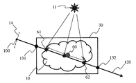
図1は、不均質な関与媒質10、例えば、雲を示している。関与媒質は、光を吸収、放射、および/または散乱する、懸濁している多数の粒子から構成される媒質である。最も単純な形態では、関与媒質は、光、例えば、光源11から受信された光を吸収のみする。光源11は、例えば、太陽などである。これは、媒質10を通過した光が減衰され、この減衰は、媒質の密度に依存することを意味している。関与媒質10は、例えば、不均質である。すなわち、媒質を構成する粒子の密度など、媒質の物理的な特性は、例えば、媒質の或るポイントと別のポイントとで異なる。関与媒質は、光と相互作用する小さな粒子で構成されるため、入射光、すなわち、方向ωin110に従って光源11から受け取られた光は、吸収されるだけでなく、散乱される。等方性散乱のある関与媒質では、光は、全方向に均一に散乱される。図1に示された雲10など、異方性散乱のある関与媒質では、光の散乱は、光の入射方向ωin110と散乱方向ωout120との間の角度に依存する。媒質10のポイントM13で散乱方向ωout120に散乱された光の量は、次の式に従って計算される。
![]()
![]()
ωout120方向の空間のポイントCに位置する視聴者12の眼に到達する、媒質のポイントM13によって散乱される光の量、すなわち、ポイントM〜ポイントPまでの進路において、ポイントMで散乱され、媒質10で減衰される光の量は、以下の通りである。ポイントPは、媒質10と視聴者12の方向である方向ωoutとの交差部にあるポイントである。
![]()
ここで、
σsは、媒質の散乱係数であり、
σaは、媒質の吸収係数であり、
σt=σs+σaは、媒質の減衰係数であり、
D(M)は、所与のポイントでの媒質の密度である。密度は、媒質10が不均質であるため、或るポイントと別のポイントとで異なっている。
p(M,ωout,ωin)は、位相関数であり、入射方向ωinから来た光がどのようにポイントMで散乱方向ωoutに散乱されるかを記述している。
Lri(M,ωin)は、入射方向ωin110から来た光のポイントMで減少した光強度であり、ポイントK〜ポイントMまでの区間で媒質10内の光の軌道により減衰した後にポイントMに到達する入射光の量を表している。Kは、媒質10と入射光線ωin110との交差ポイントであり、その値は、以下の通りである。
![]()
![]()
![]()
here,
σ s is the scattering coefficient of the medium,
σ a is the absorption coefficient of the medium,
σ t = σ s + σ a is the attenuation coefficient of the medium,
D (M) is the density of the medium at a given point. The density differs from one point to another because the medium 10 is inhomogeneous.
p (M, ω out , ω in ) is a phase function and describes how the light coming from the incident direction ω in is scattered at the point M in the scattering direction ω out .
L ri (M, ω in ) is the light intensity decreased at the point M of the light coming from the incident direction ω in 110, and after being attenuated by the light trajectory in the medium 10 in the section from the point K to the point M. It represents the amount of incident light that reaches the point M. K is a crossing point of the medium 10 and the
![]()
![]()
式2により、ポイントMによって散乱され、方向ωoutに位置する観客12の眼に到達する光の量を計算できるようになる。ωout方向に見ている視聴者によって受け取られる光の量を計算するために、軸ωout上に位置する媒質の全てのポイント、すなわち、ポイントPからポイントMmaxまでの区間に位置するポイントの寄与を合計する必要がある。PおよびMmaxは、媒質10と方向ωout120との交差部の2つのポイントである。ここで、単純な散乱による方向ωout120からP15に到達する光の合計の散乱後の輝度は、以下の通りである。
![]()
![]()
この場合、軌道C−Pをたどる光は減衰されないものと考える。 In this case, it is considered that the light that follows the trajectory CP is not attenuated.
この合計の散乱後の輝度は、ωoutを方向とする半径上のPとMmaxとの間に位置する全てのポイントの輝度を積分することによって得られる。一般に、このような積分方程式は、解析的に解くことができず、散乱した光の量のライブな推定値の場合は、なおさらである。積分は、レイマーチングのような公知の方法をディジタル的に使用して評価される。この方法においては、積分領域は、サイズδMの多数の間隔に離散化され、以下の式が得られる。

不均質な関与媒質10は、有利には、3次元要素である。なお、分かりやすくするために、図1では2次元的に描かれている。
The heterogeneous participating
変形例によれば、媒質10は、光環境を形成する複数の光源、例えば、1000個、100,000個、1,000,000個の光源によって照らされる。当業者によって知られている環境マッピング法を使用して、幾つかの離れた光源からの光の推定が行われる。環境マッピング法によれば、光環境の全ての光源が媒質10のポイントに関して光学的に無限遠に位置すると考えられる。したがって、複数の異なる光源によって発せられている光の方向は、考慮されている媒質のポイントとは無関係に同一であると考えることができる。よって、媒質の複数の異なるポイントの離間する距離による視差効果は、無視できる。変形例によれば、ポイントMでの入射光の減衰を推定するために、光の環境を表している入射の方向のセットに対して式7を利用して光の減衰を計算することが必要であるが、これにより、計算量が大幅に増加する。
According to a variant, the medium 10 is illuminated by a plurality of light sources forming a light environment, for example 1000, 100,000, 1,000,000 light sources. Estimation of light from several distant light sources is made using environmental mapping methods known by those skilled in the art. According to the environment mapping method, it is considered that all light sources in the light environment are optically located at infinity with respect to the point of the medium 10. Thus, the direction of light emitted by a plurality of different light sources can be considered to be the same regardless of the point of the medium being considered. Therefore, the parallax effect due to the distance between a plurality of different points of the medium can be ignored. According to a variation, in order to estimate the attenuation of incident light at point M, it is necessary to calculate the attenuation of
別の変形例によれば、媒質10の散乱係数σsおよび/または媒質10の吸収係数σaなどの媒質10の物理的な特性は、媒質10内の或るポイントと別のポイントとで異なり、密度もまた同様である。別の変形例によれば、係数σsおよび係数σaの2つのうちの一方のみ、または、両方が媒質内で異なり、密度は、媒質内で均一である。 According to another variant, the physical properties of the medium 10, such as the scattering coefficient σ s of the medium 10 and / or the absorption coefficient σ a of the medium 10, differ from one point in the medium 10 to another. The density is similar. According to another variant, only one or both of the coefficients σ s and σ a are different in the medium and the density is uniform in the medium.
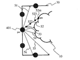
図3は、本発明の非限定的な特定の実施形態に係る、関与媒質10をレンダリングするステップを示している。有利には、境界ボックス30は、関与媒質10の周りに規定される。すなわち、関与媒質10によって形成されるボリュームは、有利には、直方体または立方体、もしくはその他の任意の形状のボックスによって囲まれる。境界ボックスは、仮想のシーン1内の関与媒質10によって占められるボリュームを迅速に推定可能にする。境界ボリュームとも呼ばれる境界ボックスの使用により、関与媒質10に係る全ての幾何学的計算を簡略化し、高速化することができる。境界ボックスの幾何学的形状は、関与媒質の形状が複雑な場合があり、関与媒質の幾何学的形状よりも単純である。境界ボックスは、関与媒質の幾何学的形状を全て含むように生成され、境界ボックスの内表面と関与媒質の外表面との間に、少なくとも所々に空間が存在する。
FIG. 3 illustrates the steps of rendering the participating
図3の実施形態によれば、関与媒質10は、この関与媒質10を観察する視点から大きな距離に、すなわち、第2の閾値よりも大きな距離に位置する。有利には、画像平面を囲む境界ボックスの投影面が、画像平面の合計表面の、例えば、5%、10%、15%よりも小さい場合には、関与媒質は、第2の閾値よりも大きな距離にあると考えられる。したがって、人が関与媒質10を見る方向に関わらず、観察の方向は、関与媒質10を囲む境界ボックスの中心P300を通過すると考えることができる。よって、有利には、Pを中心とする球は、i方向31、32、33、34、35、36、37、および3iにサンプリングされる。iは、2以上の整数、例えば、10、100、1000、または10000である。
According to the embodiment of FIG. 3, the participating
これらの方向31〜3iの各々に対して、境界ボックスの表面との交差ポイントが当業者によって公知な任意の幾何学的方法によって計算される。方向31を例にとってみると、方向31と境界ボックス30の表面との交差ポイントは、ポイントP0310に対応する。この交差ポイントP0から開始して、直線の区間[P0P]は、P300に向かって方向31に沿って、ポイントPm31mに関連付けられた密度値が第1の閾値よりも大きいポイントPm31mに至るまで続く。有利には、第1の閾値は、関与媒質の粒子の最小密度を表す密度値に対応する。有利には、ポイントPmは、方向31と境界ボックスの表面から開始する関与媒質10との第1の交差部に対応する。ポイントPm31mは、例えば、レイトレーシング法またはレイマーチング法を使用して求められる。変形例によれば、ポイントPm310は、二分サーチ法を使用して求められ、この二分サーチ法に従って、第1の閾値よりも大きな密度値が関連付けられているポイントPm31mが見つかるまで、区間[P0P]が反復して半分にカットされる。有利には、第1の閾値は、所定のシステム値である。変形例によれば、第1の閾値は、関与媒質のレンダリングを実行するシステムのユーザによって入力されるパラメータである。
For each of these
交差ポイントPm31mが決定されると、この第1の交差ポイントPm31m(このポイントは方向31と関与媒質10の外側の包絡面(換言すれば、表面)との交差部に対応する。)が第2の交差ポイントP0310(このポイントが方向31と境界ボックスの表面との交差部に対応する。)から離間する距離が決定される。この距離は、基準||P0Pm||に対応する。この距離は、仮想のシーン1のこれらのポイントP0およびPmの座標から決定される。
When the
有利には、この処理は、関連する方向と媒質の外側の包絡面との交差部に対応する、第1の交差ポイントと、関連する方向と境界ボックス30の表面との交差部に対応する、第2の交差ポイントとが離間する距離を推定するために、残りの方向32〜3iの各々に対して繰り返される。各方向毎の、第2の交差ポイントから第1の交差ポイントが離間するこれらの距離は、例えば、メモリに記憶され、関与媒質をサンプリングするために行われる計算において再使用される。
Advantageously, this process corresponds to the intersection of the first intersection point and the associated direction with the surface of the
有利な変形例によれば、各方向31〜3iに沿って第2の交差ポイントから第1の交差ポイントが離間するこれらの距離は、例えば、球面調和関数などの基底関数のセットに投影される。関数空間の各関数は、基底関数の線形結合として記述することができる。基底関数は、関数空間に対する基底の要素である。球関数の正規直交基底を使用することによって、ポイントPでの第1のポイントと第2のポイントとの間の距離を表す関数を、以下のように表現することができる。
![]()
ここで、D(P)は、第1の交差ポイントと第2の交差ポイントとの間の距離を表す極限関数であり、
Crj(M)は、基底関数Bj(P)の(合計でNc個の係数)j番目の投影係数であり、
Crj(P)は、中心Pの球Ω上の整数によって、すなわち、以下のように規定される。
![]()
![]()
Here, D (P) is a limit function representing the distance between the first intersection point and the second intersection point,
Cr j (M) is the jth projection coefficient (Nc coefficients in total) of the basis function B j (P),
Cr j (P) is defined by an integer on the sphere Ω of the center P, that is, as follows.
![]()
このように計算された基底関数の投影係数のセット(例えば、16または32個の係数)は、GPUのメモリ・テーブルに記憶される。これらの係数は、球Ωを形成するi方向に沿って第2の交差ポイントから第1の交差ポイントが離間する距離を表す。極限関数を表す投影係数の使用により、第1の交差ポイントと第2の交差ポイントとの間の距離情報を記憶するのに必要なメモリ空間を制限することができる。 The set of basis function projection coefficients thus calculated (eg, 16 or 32 coefficients) is stored in the GPU memory table. These coefficients represent the distance that the first intersection point is spaced from the second intersection point along the i direction forming the sphere Ω. The use of projection coefficients representing limit functions can limit the memory space required to store distance information between the first intersection point and the second intersection point.
変形例によれば、距離は、ウェーブレット・タイプの基底関数に投影されるものである。しかしながら、球面調和関数は、特に、穏やかに変化する距離を示すのに適している。これは、一般的には、雲などの半透明な媒質の範囲の場合である。 According to a variant, the distance is projected onto a wavelet-type basis function. However, spherical harmonics are particularly suitable for indicating a gently changing distance. This is generally the case for a range of translucent media such as clouds.
変形例によれば、(各方向31〜3iと関与媒質10との交差部に対応する)第1の交差ポイントから境界ボックスの中心P300が離間する距離が第2の交差ポイントから第1の交差ポイントが離間する距離の代わりに推定される。したがって、これらの距離の極限関数は、上述したように決定される。
According to the modification, the distance at which the center P300 of the bounding box is separated from the first intersection point (corresponding to the intersection between each
図4および図5は、境界ボックス30の表面と関与媒質10の外側の包絡面との間の距離を推定する第2の実施形態を例示している。第2の実施形態は、視点から平均的に離れた距離、すなわち、図面を参照して説明された第1の実施形態で規定された第2の閾値未満であるが、距離を表す第3の閾値よりも大きい距離に位置する関与媒質を表現するのにより適している。関与媒質は、画像平面上の媒質を囲む境界ボックスの投影された表面が画像平面の合計表面の25%または30%未満である場合には、第3の閾値よりも大きな距離にあると考えられる。本実施形態は、より具体的には、全ての視線方向が関与媒質10の同じポイントを通ると考えられないような視点からの距離に位置する関与媒質を表現するのに適している。
4 and 5 illustrate a second embodiment for estimating the distance between the surface of the
図4は、第2の実施形態の第1のステップを例示している。このステップの間に、関与媒質10と境を接する境界ボックス30の表面がj個のサンプル401、402、・・・、4120、40jにサンプリングされる。ここで、jは、2以上の整数である。サンプルの数jは、特定の精度で境界ボックスの表面を表すように選択されている。精度は、本発明が実施されるグラフィックス・カードによって取り扱い可能な計算の数に従って選択され、特にライブな制約が関与媒質10を含む仮想のシーンのレンダリングに存在する場合このように選択される。
FIG. 4 illustrates the first step of the second embodiment. During this step, the surface of the
図5は、複数のサンプル401〜40jのうちの1つのサンプル401を例にとった、第2の実施形態の第2のステップを例示している。半球は、サンプル401(ポイントP0と同じであると理解することができる。)を中心とし、境界ボックスの表面の部分を底面とし、主に、境界ボックスの内部に向かっている、すなわち、関与媒質に向かっているものとして規定する。この半球は、複数のk方向51、52、53、54、55、5kにサンプリングされ、kは2以上の整数である。
FIG. 5 illustrates the second step of the second embodiment taking one
これらの方向51〜5kの各々に対して、境界ボックスの表面との交差ポイントは、第2の交差ポイントと呼ばれ、第1の実施形態では計算されない。なぜならば、既知であり、考慮されているサンプル401を表すポイントP0に対応するからである。P0401から開始する方向52を例にとると、方向52の範囲は、P0401から移動して、ポイント521、522、および523を通った後、ポイントPm52mに到達するまでであり、ポイントPm52mに関連付けられた密度値は、第1の閾値よりも大きい。有利には、第1の閾値は、関与媒質の粒子の最小代表密度を表す密度値に対応する。有利には、ポイントPm52mは、境界ボックスの表面からスタートして、方向52と関与媒質10との最初の交差部に対応する。図3を参照して説明した例と同様に、例えば、レイトレーシング法を使用すること、または、二分サーチ法を使用することによって、ポイントPm52mがサーチされる。
For each of these directions 51-5k, the intersection point with the surface of the bounding box is called the second intersection point and is not calculated in the first embodiment. This is because it corresponds to the point P 0 that represents the known and considered
交差ポイントPm52m(第1の交差ポイントと呼ばれる)が決定されると、第1の交差ポイントPm52mを第2の交差ポイントP0401から離間する距離が決定される。この距離は、基準||P0Pm||に対応し、仮想のシーン1のこれらのポイントP0およびPmに関連付けられた座標から決定される。
When the intersection point Pm52m (referred to as the first intersection point) is determined, the distance that separates the first intersection point Pm52m from the second
有利には、この処理は、関連する方向と媒質の外側の包絡面との交差部に対応する第1の交差ポイントと、関連する方向と境界ボックス30の表面との交差部に対応する第2の交差ポイント、すなわち、境界ボックスの表面の考慮されているサンプルに対応する半球の中心とが離間する距離を推定するために、残りの方向52〜5kの各々に対して繰り返される。各方向に対して、第2の交差ポイントから第1の交差ポイントが離間するこれらの距離は、例えば、メモリに記憶され、関与媒質をサンプリングするために行われる計算において再使用される。有利な変形例によれば、各方向35〜5iに沿って第2の交差ポイントから第1の交差ポイントが離間するこれらの距離は、例えば、図3に例示された実施形態に関して説明した球面調和関数と同様の原理に従った半球面調和関数など、基底関数のセットに投影される。このように計算された基底関数の投影係数のセットNc(例えば、16個または32個の係数)は、そこで、GPUのメモリ・テーブルに記憶される。これらの係数は、球Ωを形成するk個の方向に沿った第2の交差ポイントから第1の交差ポイントが離間する距離を表している。
Advantageously, the process includes a first intersection point corresponding to the intersection of the associated direction and the outer envelope surface of the medium, and a second intersection corresponding to the intersection of the associated direction and the surface of the
そこで、有利な方法で、同一の処理が境界ボックス30の表面を表すサンプル401〜40jの全てまたは部分に対して繰り返される。したがって、考慮されているサンプルを起点とするk個の方向と関与媒質10の包絡面との複数の異なる交差ポイントから考慮されているサンプルが離間する距離を表す距離情報が、各サンプル401〜40jに対して決定される。よって、距離を表す情報(すなわち、複数の距離値または距離値を表す複数の投影係数)が境界ボックス30の表面の各々の考慮されているサンプルに関連付けられる(そして、GPUのメモリ・テーブルに記憶される)。
Thus, in an advantageous manner, the same process is repeated for all or part of the samples 401-40j representing the surface of the
図6は、非限定的な本発明の特定の実施形態に係る、関与媒質を横断する視線方向のサンプリングを例示している。 FIG. 6 illustrates line-of-sight sampling across a participating medium, according to a specific embodiment of the invention that is non-limiting.
観客が仮想のシーン1を観察する方向に対応する所与の視線方向120で、観客の視点に従って画像を表現する画像平面14の画素が関連付けられている各方向に対して、一方を視線方向120とし、他方を関与媒質10とした場合の、これらの間の、第3の交差ポイントと呼ばれる、2つの交差ポイント61および62が、メモリに記憶された距離情報を使用して決定される。境界ボックス30の表面と関与媒質10の外側の包絡面との間の距離を表す距離情報は、有利には、関与媒質10の一般的な形状を規定し、これにより、視線方向120と関与媒質10との実際の交差部が迅速に見つけられるようにする。
For each direction associated with pixels of the
関与媒質10が視点から平均的に離れた位置にある場合、すなわち、所定の第3の閾値よりも大きな距離に位置している場合には、第3の交差ポイントを決定する前に、第4の交差ポイントと呼ばれる、視線方向と境界ボリュームとの交差ポイント1201および1202が決定される。事前に第4の交差ポイント1201、1202を決定しておくことによって、第3の交差ポイント61、62を推定するために何の距離情報を使用するかが分かるようになる。実際、図4および図5に関して説明したように、距離情報は、境界ボックス30の表面の各サンプル401〜40jに関連付けられる。何の距離情報を使用するかを知るために、結果として、境界ボックスの表面の何のサンプルを参照しなければならないかを知ることが必要となる。例えば、決定された第4の交差ポイント1201がサンプル・ポイント401〜40jのうちのいずれかに対応しない場合、この4番目の交差ポイントに関連付けられた距離情報は、この第4の交差ポイントを囲む、関連付けられた距離情報が利用可能なサンプル・ポイントの、この関連付けられた距離情報を補間することによって計算される。
If the participating
第3の交差ポイント61、62(このポイントは視線方向120と関与媒質10との交差ポイントである。)が決定されると、視線方向120と関与媒質10とに共通する区間に対応する直線の区間、すなわち、2つの交差ポイント61、62との直線の区間は、複数のサンプル60にサンプリングされる。サンプルの数は、直線の区間を忠実に表現することと、関与媒質のレンダリングに伴う計算コストとが良好に折り合うように選択される。サンプルの数が多くなるほど、関与媒質のレンダリングに必要な計算コストが高くなる。
When the third intersection points 61 and 62 (this point is an intersection point between the line-of-
有利には、関与媒質の完全な表現、さらに、そこから開始される関与媒質の(考慮された視点からの)完全なレンダリングを得るために、幾つかの視線方向に対して同一のサンプリング処理が繰り返される。したがって、例えば、図1に関して説明した式を使用することによって、視線方向に関与媒質10によって散乱された光の量を推定することが可能である。
Advantageously, the same sampling process is used for several gaze directions in order to obtain a complete representation of the participating medium, as well as a complete rendering (from the considered viewpoint) of the participating medium starting from it. Repeated. Thus, for example, by using the formula described with respect to FIG. 1, it is possible to estimate the amount of light scattered by the participating
変形例によれば、サンプリング処理は、幾つかの視点に対して繰り返される。例えば、関与媒質10を含む仮想のシーン1がビデオ・ゲームのシーンであり、そのシーンでプレイヤーのアバターが動いている場合、シーンの視点は、シーン内でのアバターの動きに合わせて変化する。
According to a variant, the sampling process is repeated for several viewpoints. For example, when the
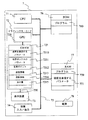
図7は、関与媒質10のレンダリング、さらに、1つ以上の画像を表示するための信号の生成に適した装置7のハードウェアの実施形態を図式的に例示している。装置7は、例えば、パーソナル・コンピュータPC、ラップトップ、または、ゲーム・コンソールに対応する。
FIG. 7 schematically illustrates a hardware embodiment of the
装置7は、アドレスおよびデータ・バス75によって共に結合された以下の構成要素を含む。アドレスおよびデータ・バス75は、さらに、クロック信号を搬送する。
・マイクロプロセッサ(またはCPU)71
・幾つかのグラフィックス・プロセッシング・ユニット(またはGPU)720と、GRAM(“Graphical Random Access Memory”)タイプのランダム・アクセス・メモリ721と、を含むグラフィックス・カード72
・ROM(“Read Only Memory”)タイプの不揮発性メモリ76
・ランダム・アクセス・メモリ、すなわち、RAM77
・例えば、キーボード、マウス、ウェブカメラなどの1つ以上のI/O(「入力/出力」)装置74
・電源78
Microprocessor (or CPU) 71
A
ROM (“Read Only Memory”) type
Random access memory,
One or more I / O (“input / output”)
・
装置7は、さらに、特に、例えば、ライブで、グラフィックス・カード72において計算、合成されたコンピュータで生成されたグラフィックスのレンダリング(描画)を表示するための、グラフィックス・カード72に直接結合されたディスプレイ画面タイプの表示装置73を含む。表示装置73をグラフィックス・カード72に結合する専用のバスを使用することで、データの伝送レートが遥かに高くなり、その結果、グラフィックス・カードによって合成された画像を表示するための待ち時間(レイテンシ)が減少するという利点が得られる。一変形例によれば、表示装置は、装置7の外部に存在し、表示信号を伝送するケーブルによって装置7に結合されている。装置7は、例えば、グラフィックス・カード72であり、例えば、LCDやプラズマ・スクリーン、ビデオ・プロジェクタなどの外部表示手段に表示信号を伝送するのに適した伝送媒体またはコネクタ(図7に図示せず)を含む。
The
なお、メモリ72、76、および77の説明に使用されている単語「レジスタ」は、上述したメモリの各々において、小容量(幾らかのバイナリ・データ)のメモリ領域、さらに、大容量(プログラム全体を記憶可能にするか、計算、または表示されるデータを表すデータの全て或いは部分を記憶できるようにするもの)のメモリ領域を指定する。
Note that the word “register” used in the description of the
電源が立ち上げられると、マイクロプロセッサ71は、RAM77に格納されているプログラムのインストラクションをロードし、実行する。
When the power is turned on, the
ランダム・アクセス・メモリ77は、特に、以下のものを含む。
・レジスタ770における、装置7上でスイッチング動作を担うマイクロプロセッサ71の動作プログラム
・関与媒質10を表現するパラメータ771(例えば、密度のパラメータ、光吸収係数、および光散乱係数)
The
An operation program of the
以下に説明する本発明に特定の方法のステップを実施するアルゴリズムは、これらのステップを実施する装置7に関連付けられたグラフィックス・カード72のGRAMメモリ77に記憶される。電源が立ち上げられ、媒質を表現するパラメータ770がRAM77にロードされると、グラフィックス・カード720のグラフィックス・プロセッシング・ユニット(GPU)720は、これらのパラメータをGRAM721にロードし、例えば、HLSL(“High Level Shader Language”)言語、GLSL(“OpenGL Shading Language”)言語を使用して、「シェーダ(shader)」タイプのマイクロプログラムの形態のこれらのアルゴリズムのインストラクションを実行する。
The algorithms that implement the method steps specific to the invention described below are stored in the
GRAMのランダム・アクセス・メモリ721
は、特に、以下の構成要素を含む。
・レジスタ7210における、媒質10を表現するパラメータ
・境界ボックスを表現するパラメータ7211(例えば、ボックスの幅、高さ、および深さを表す値と共に角度のうちの1つが関連付けられたポイントの座標)
・第1、第2、第3、および/または第4の交差ポイントを表現するパラメータ7212(例えば、交差ポイントの座標)
・境界ボックス30の表面と媒質10の外側の包絡面との間の距離を表す値7213
・境界ボックス30の表面と媒体10の外側の包絡面との間の距離値を表す投影係数7214
・1つ以上の観察方向に沿った媒質10によって散乱された光の量を表す値7215
GRAM
In particular includes the following components:
A parameter representing the medium 10 in the
A parameter 7212 (eg, the coordinates of the intersection point) representing the first, second, third, and / or fourth intersection point
A
A
A
変形例によれば、GRAM721において利用可能なメモリの記憶容量が十分でない場合には、パラメータ7211、7212、および値7213、7214、および7215を記憶するために、RAM77の一部がCPU71によって割り当てられる。しかしながら、この変形例では、GPUに格納されるマイクロプログラムから合成される媒質10を表現したものからなる画像の合成のレイテンシ時間が長くなる。その理由は、データがグラフィックス・カードからランダム・アクセス・メモリ77にバス75によって伝送されなければならず、バス75の伝送容量は、一般的には、GPUからGRAMにデータを伝送するために、さらに、GRAMからGPUにデータを伝送するために、グラフィックス・カードにおいて利用可能なものよりも小さいからである。
According to a modification, if the memory capacity available in
別の変形例によれば、電源78および/または表示装置73は、装置7の外部に存在する。
According to another variant, the
図8は、本発明の第1の非限定的な特定の有利な実施形態に係る、受信機7において実施される関与媒質10をレンダリングする方法を示している。
FIG. 8 shows a method for rendering the participating
初期化ステップ80において、装置7の様々なパラメータが更新される。特に、関与媒質10を表現するパラメータが何らかの方法で初期化される。
In an
次に、ステップ81において、関与媒質10を囲む境界ボックスによって形成されたボリュームのポイントを中心とする少なくとも1つの半球が、ボリュームのこのポイントを起点とする複数の方向によって規定される。第1の実施形態によれば、境界ボックスを形成したボリュームのポイントは、境界ボックスの中心に対応し、特に、関与媒質が視点から遠く離れている場合、すなわち、関与媒質がレンダリングされる第2の閾値よりも大きな距離にある場合に、境界ボックスの中心に対応する。この第1の実施形態によれば、球を形成する2つの半球が複数の方向によって規定される。第2の実施形態によれば、境界ボックスの表面の複数のポイントを中心とする幾つかの半球が、各々が境界ボックスの表面のポイントの1つを起点とする複数の方向によって規定される。この第2の実施形態は、関与媒質が視点から平均距離に離れた位置にある場合、すなわち、第1の実施形態において規定される第2の閾値未満であるが、第3の閾値よりも大きな距離にある場合に、有利である。
Next, at
次に、ステップ82において、前のステップの間に規定された1つまたは複数の半球を形成する1つ以上の方向に対して第1の交差ポイントが推定される。その方向の数の選択は、この方法を実施する装置の計算能力、さらに/または、必要とされる関与媒質の表現またはレンダリングの品質に従って行われる。方向の数が多いほど、計算のコストが高くなり、品質が向上する。考慮されている方向が、この考慮されている方向と境界ボックスの表面と間の交差部に対応する第2の交差ポイントからスタートする場合、推定された交差ポイントは、半球の所与の方向に対して、考慮されている方向と関与媒質との交差部に対応する。第2の実施形態の場合には、この第2の交差ポイントは、考慮されている方向を含む半球の中心に対応する。有利には、第1の交差ポイントは、考慮されている方向の範囲を、第2の交差ポイントからスタートすることによって推定され、第1の交差ポイントは、関連付けられている密度情報に関連する基準を満たすこの方法の第1のポイント、すなわち、第1の密度閾値よりも大きな密度値が関連付けられている第1のポイントに対応する。第1の交差ポイントが決定されると、第1の交差ポイントが離間する距離は、メモリに記憶される前に決定される。複数の方向に対する第1および第2の交差ポイントの間の複数の距離を決定することにより、境界ボックスの表面を基準とした、関与媒質の外形を規定することができる。換言すれば、これは、関与媒質の形状または外側の包絡面を表現する極限関数を規定することを意味する。変形例によれば、メモリ・リソースを節約するために、この極限関数は、投影係数のセットによって関数基底の空間において表現される。投影係数の記憶は、第1の交差ポイントと第2の交差ポイントとが離間する距離の値を記憶するよりも使用するメモリ空間は少ないが、この距離情報を復元することができる。
Next, at
最後に、ステップ83において、第1の交差ポイントと第2の交差ポイントとが離間する距離を表現する情報から、すなわち、距離値自体から、または、これらの距離値を表現する投影係数から、2つの第3の交差ポイントが推定される。2つの第3の交差ポイントは、一方を媒質が所与の視点から観察される視野方向とし、他方を既に推定された距離情報によって規定される関与媒質の外側の包絡面とした場合の、これらの間の交差部に対応する。
Finally, in
変形例によれば、この方法は、さらに、2つの第3の交差ポイントの間に含まれる直線の区間、すなわち、視線方向と関与媒質10のボリュームとによって形成される交差部に対応する直線の区間のサンプリング・ステップをさらに含む。有利には、視線方向に従った関与媒質のサンプリングにより、観察の方向に対応する画像平面の画素上の関与媒質をレンダリングするために、観察の方向に沿った関与媒質によって散乱された光の量が計算できるようになる。有利には、関与媒質10の完全な画像のレンダリングを行うために、複数の観察の方向に対して、第3の交差ポイントを決定するステップおよび関与媒質をサンプリングするステップが繰り返される。
According to a variant, the method further includes a straight line segment between two third intersection points, i.e. a straight line corresponding to the intersection formed by the line-of-sight direction and the volume of the participating
当然のことながら、本発明は、上述した実施形態に限定されるものではない。特に、本発明は、関与媒質をレンダリングする方法に限定されるものではなく、均質な関与媒質であるか不均質な関与媒質であるかに関わらず、関与媒質をモデル化または表現する方法に拡張される。本発明は、さらに、この方法を実施するどのような装置にも、具体的には、少なくとも1つのGPUを含む、全ての装置、レンダリングまたはモデル化を行う方法のステップを実行するプログラム・コード・インストラクションを含むコンピュータ・プログラム製品、さらに、レンダリングまたはモデル化を行う方法を実施する実行可能なインストラクションが記憶される任意の記憶手段(例えば、RAMまたはGRAMタイプ、フラッシュ・メモリ、CD、DVD)に拡張される。図1〜図6を参照して説明したステップの実施態様は、シェーダー・タイプのマイクロプログラムの実施態様に限定されるものではなく、任意のプログラム・タイプ、例えば、CPUタイプのマイクロプロセッサによって実行可能なプログラムの実施態様にも拡張可能である。 Of course, the present invention is not limited to the embodiments described above. In particular, the present invention is not limited to methods for rendering participating media, but extends to methods for modeling or representing participating media regardless of whether they are homogeneous or inhomogeneous participating media. Is done. The invention further relates to any device that implements this method, in particular a program code that performs the steps of the method of rendering or modeling all devices, including at least one GPU. Extended to any computer program product that includes instructions, and any storage means (eg, RAM or GRAM type, flash memory, CD, DVD) that stores executable instructions that implement the method of rendering or modeling Is done. The implementation of the steps described with reference to FIGS. 1-6 is not limited to the implementation of shader-type microprograms, but can be performed by any program type, for example, a CPU-type microprocessor. The present invention can be extended to various program embodiments.
有利には、投影係数の推定に使用される基底関数は、球面調和または半球面調和タイプ、或いは、球面ウェーブレット・タイプまたは半球面ウェーブレット・タイプの関数である。 Advantageously, the basis function used for the estimation of the projection coefficients is a spherical harmonic or hemispherical harmonic type, or a spherical wavelet type or hemispherical wavelet type function.
本発明の使用は、ライブでの使用に限定されるものではなく他の使用にも拡張することがきる。例えば、本発明を、例えば、コンピュータによって生成されるピクチャのレンダリングのレコーディング・スタジオにおけるいわゆるポストプロダクションの処理動作に使用することができる。ポストプロダクションにおける本発明の実施態様により、特に、リアリズムの観点から、良好な視覚レンダリングが実現する一方で、必要な計算時間が短縮するという利点が得られる。 The use of the present invention is not limited to live use but can be extended to other uses. For example, the present invention can be used for so-called post-production processing operations in a recording studio for rendering computer generated pictures, for example. The embodiment of the invention in post-production offers the advantage of reducing the required computation time while achieving good visual rendering, especially from a realism point of view.
本発明は、さらに、不均質な関与媒質によって散乱される光の量が計算され、結果として生ずる光を表現する情報が画像の画素の表示に使用され、各画素は、観察の方向ωoutに従った観察方向に対応する、2次元または3次元における、ビデオ画像を合成する方法に関する。観客の複数の視点に適応するために、画像の画素毎に、表示用の計算された光の値が、再度計算される。 The invention further calculates the amount of light scattered by the inhomogeneous participating medium, and the information representing the resulting light is used to display the pixels of the image, each pixel in the viewing direction ω out . The present invention relates to a method for synthesizing video images in two or three dimensions corresponding to the observed viewing direction. In order to adapt to the audience's multiple viewpoints, the calculated light values for display are recalculated for each pixel of the image.
本発明は、例えば、PCまたはラップトップ・タイプのコンピュータにおいて実行可能なプログラムによるものであるか、ライブ画像を生成し、表示する専用のゲーム・コンソールにおけるものであるかどうかに関わらず、ビデオ・ゲーム・アプリケーションにおいて使用することができる。有利には、図7に関して説明した装置7は、キーボードおよび/またはジョイスティックなど、インタラクション手段を有する。例えば、音声認識など、コマンドを入力するための他の方式も可能である。
The present invention, for example, whether it is by a program executable on a PC or laptop type computer or in a dedicated game console that generates and displays live images. It can be used in game applications. Advantageously, the
Claims (14)
前記境界ボックスによって形成されるボリュームの少なくとも1つのポイント(300;401)に対して、該少なくとも1つのポイント(300;401)を起点とし、該少なくとも1つのポイント(300;401)を中心とする底面を有する少なくとも1つの半球に従って分布される方向のセット(31〜3i;51〜5k)を推定するステップ(81)と、
前記推定された方向のセット(31〜3i;51〜5k)の少なくとも一部の各方向に対して、前記方向と前記関与媒質(10)との交差部に対応する、関連付けられた密度値が第1の閾値よりも大きい第1の交差ポイント(31m;52m)を推定するステップ(82)であって、該第1の交差ポイント(31m;52m)は、前記方向と前記境界ボックス(30)との交差部に対応する第2の交差ポイント(310;401)からスタートすることにより推定される、前記ステップ(82)と、
前記推定された方向のセット(31〜3i;51〜5k)の少なくとも一部の各方向に対して、前記第2の交差ポイント(310;401)から前記第1の交差ポイント(31m;52m)が離間する距離を表す情報から、前記視線方向(120)と前記関与媒質(10)との交差部に対応する第3の交差ポイント(61、62)を推定するステップ(83)と、を含む、前記方法。 A method of rendering a participating medium (10) included in a scene (1), the participating medium being delimited by a bounding box (30), the participating medium from a viewpoint (14) according to a line-of-sight direction (120) Rendered from the viewpoint (14) at a predetermined distance;
For at least one point (300; 401) of the volume formed by the bounding box, start from the at least one point (300; 401) and center around the at least one point (300; 401) Estimating a set of directions (31-3i; 51-5k) distributed according to at least one hemisphere having a bottom surface;
For each direction of at least a portion of the estimated set of directions (31-3i; 51-5k), an associated density value corresponding to the intersection of the direction and the participating medium (10) is Estimating (82) a first intersection point (31m; 52m) that is greater than a first threshold, said first intersection point (31m; 52m) comprising said direction and said bounding box (30); Said step (82) estimated by starting from a second intersection point (310; 401) corresponding to the intersection with
For each direction of at least a part of the estimated set of directions (31-3i; 51-5k), from the second intersection point (310; 401) to the first intersection point (31m; 52m). Estimating a third intersection point (61, 62) corresponding to an intersection of the line-of-sight direction (120) and the participating medium (10) from information representing a distance of , Said method.
前記複数のサンプル(401〜40j)の少なくとも一部に対応する複数のポイント(401)に対して方向のセット(51〜5k)が推定され、方向の各セットは該複数のサンプルのうちの考慮されているサンプル(401)を中心とする半球に従って推定され、該半球の前記底面は前記境界ボックスの前記表面に属し、該半球は前記境界ボックスの内部に向いており、
前記第3の交差ポイント(61、62)は、さらに、前記視線方向(120)と前記境界ボックス(30)との交差部に対応する第4の交差ポイント(131)から推定される、請求項1または2に記載の方法。 The distance by which the participating medium is separated from the viewpoint (14) according to the line-of-sight direction (120) is less than a second threshold value and greater than a third threshold value, and the method applies the surface of the bounding box to a plurality of samples ( 401-40j) including a step of sampling,
A set of directions (51-5k) is estimated for a plurality of points (401) corresponding to at least a portion of the plurality of samples (401-40j), and each set of directions is a consideration of the plurality of samples. Is estimated according to a hemisphere centered on the sample (401), the bottom surface of the hemisphere belongs to the surface of the bounding box, the hemisphere facing the interior of the bounding box;
The third intersection point (61, 62) is further estimated from a fourth intersection point (131) corresponding to an intersection of the line-of-sight direction (120) and the bounding box (30). The method according to 1 or 2.
前記境界ボックスによって形成されるボリュームの少なくとも1つのポイント(300;401)に対して、該少なくとも1つのポイント(300;401)を起点とし、該少なくとも1つのポイント(300;401)を中心とする底面を有する少なくとも1つの半球に従って分布される方向のセット(31〜3i;51〜5k)を推定し、
前記推定された方向のセット(31〜3i;51〜5k)の少なくとも一部の各方向に対して、前記方向と前記関与媒質(10)との交差部に対応する、関連付けられた密度値が第1の閾値よりも大きい第1の交差ポイント(31m;52m)を推定し、前記第1の交差ポイント(31m;52m)は、前記方向と前記境界ボックス(30)との交差部に対応する第2の交差ポイント(310;401)からスタートすることにより推定され、
前記推定された方向のセット(31〜3i;51〜5k)の少なくとも一部の各方向に対して、前記第2の交差ポイント(310;401)から前記第1の交差ポイント(31m;52m)が離間する距離を表す情報から、前記視線方向(120)と前記関与媒質(10)との交差部に対応する第3の交差ポイント(61、62)を推定するように構成されてなることを特徴とする、前記装置。 An apparatus (7) configured to render a participating medium (10) contained in a scene (1), the participating medium (10) being delimited by a bounding box (30), the participating medium ( 10) is rendered from the viewpoint (14) at a predetermined distance from the viewpoint (14) according to the viewing direction (120), the apparatus comprises at least one processor (720), the at least one processor comprising:
For at least one point (300; 401) of the volume formed by the bounding box, start from the at least one point (300; 401) and center around the at least one point (300; 401) Estimating a set of directions (31-3i; 51-5k) distributed according to at least one hemisphere having a base;
For each direction of at least a portion of the estimated set of directions (31-3i; 51-5k), an associated density value corresponding to the intersection of the direction and the participating medium (10) is A first intersection point (31m; 52m) greater than a first threshold is estimated, and the first intersection point (31m; 52m) corresponds to the intersection of the direction and the bounding box (30). Estimated by starting from the second intersection point (310; 401),
For each direction of at least a part of the estimated set of directions (31-3i; 51-5k), from the second intersection point (310; 401) to the first intersection point (31m; 52m). Is configured to estimate the third intersection point (61, 62) corresponding to the intersection between the line-of-sight direction (120) and the participating medium (10) from the information indicating the distance between the two. Said device.
Applications Claiming Priority (3)
| Application Number | Priority Date | Filing Date | Title |
|---|---|---|---|
| FR1252675 | 2012-03-26 | ||
| FR1252675A FR2988502A1 (en) | 2012-03-26 | 2012-03-26 | METHOD FOR REPRESENTING A PARTICIPATING ENVIRONMENT IN A SCENE AND CORRESPONDING DEVICE |
| PCT/EP2013/056130 WO2013144029A1 (en) | 2012-03-26 | 2013-03-22 | Method for representing a participating media in a scene and corresponding device |
Publications (2)
| Publication Number | Publication Date |
|---|---|
| JP2015515058A true JP2015515058A (en) | 2015-05-21 |
| JP2015515058A5 JP2015515058A5 (en) | 2016-05-19 |
Family
ID=48045470
Family Applications (1)
| Application Number | Title | Priority Date | Filing Date |
|---|---|---|---|
| JP2015502248A Pending JP2015515058A (en) | 2012-03-26 | 2013-03-22 | Method and corresponding apparatus for representing participating media in a scene |
Country Status (8)
| Country | Link |
|---|---|
| US (1) | US9626791B2 (en) |
| EP (1) | EP2831846B1 (en) |
| JP (1) | JP2015515058A (en) |
| KR (1) | KR20140144714A (en) |
| CN (1) | CN104272351A (en) |
| CA (1) | CA2866589C (en) |
| FR (1) | FR2988502A1 (en) |
| WO (1) | WO2013144029A1 (en) |
Families Citing this family (3)
| Publication number | Priority date | Publication date | Assignee | Title |
|---|---|---|---|---|
| WO2012000847A2 (en) * | 2010-07-01 | 2012-01-05 | Thomson Licensing | Method of estimating diffusion of light |
| CN107807963B (en) * | 2017-10-11 | 2021-04-06 | 贵州电网有限责任公司 | Method for rapidly searching power transmission network line collection area based on divide-and-conquer strategy |
| EP3595319A1 (en) * | 2018-07-12 | 2020-01-15 | InterDigital VC Holdings, Inc. | Methods and apparatus for volumetric video transport |
Citations (5)
| Publication number | Priority date | Publication date | Assignee | Title |
|---|---|---|---|---|
| JP2001283251A (en) * | 2000-02-28 | 2001-10-12 | Mitsubishi Electric Research Laboratories Inc | Method and device for rendering graphic object |
| US20090006044A1 (en) * | 2007-06-26 | 2009-01-01 | Microsoft Corporation | Real-Time Rendering of Light-Scattering Media |
| US20090006051A1 (en) * | 2007-06-29 | 2009-01-01 | Microsoft Corporation | Real-Time Rendering of Light-Scattering Media |
| JP2009545075A (en) * | 2006-07-28 | 2009-12-17 | インテル コーポレイション | Real-time multi-resolution 3D collision detection using cube maps |
| US20100085360A1 (en) * | 2008-10-04 | 2010-04-08 | Microsoft Corporation | Rendering in scattering media |
Family Cites Families (4)
| Publication number | Priority date | Publication date | Assignee | Title |
|---|---|---|---|---|
| US7940269B2 (en) * | 2007-06-29 | 2011-05-10 | Microsoft Corporation | Real-time rendering of light-scattering media |
| US20090284524A1 (en) * | 2008-05-14 | 2009-11-19 | Robert Allen Shearer | Optimized Graphical Calculation Performance by Removing Divide Requirements |
| CN101894390B (en) | 2010-06-29 | 2012-07-04 | 浙江大学 | Ray tracing method for non-constant refractive index medium |
| FR2964776A1 (en) | 2010-09-14 | 2012-03-16 | Thomson Licensing | METHOD FOR ESTIMATING LIGHT DISTRIBUTION IN A HOMOGENEOUS ENVIRONMENT |
-
2012
- 2012-03-26 FR FR1252675A patent/FR2988502A1/en not_active Withdrawn
-
2013
- 2013-03-22 KR KR1020147029720A patent/KR20140144714A/en not_active Application Discontinuation
- 2013-03-22 EP EP13713818.6A patent/EP2831846B1/en active Active
- 2013-03-22 CN CN201380023004.5A patent/CN104272351A/en active Pending
- 2013-03-22 US US14/386,375 patent/US9626791B2/en active Active
- 2013-03-22 WO PCT/EP2013/056130 patent/WO2013144029A1/en active Application Filing
- 2013-03-22 CA CA2866589A patent/CA2866589C/en active Active
- 2013-03-22 JP JP2015502248A patent/JP2015515058A/en active Pending
Patent Citations (5)
| Publication number | Priority date | Publication date | Assignee | Title |
|---|---|---|---|---|
| JP2001283251A (en) * | 2000-02-28 | 2001-10-12 | Mitsubishi Electric Research Laboratories Inc | Method and device for rendering graphic object |
| JP2009545075A (en) * | 2006-07-28 | 2009-12-17 | インテル コーポレイション | Real-time multi-resolution 3D collision detection using cube maps |
| US20090006044A1 (en) * | 2007-06-26 | 2009-01-01 | Microsoft Corporation | Real-Time Rendering of Light-Scattering Media |
| US20090006051A1 (en) * | 2007-06-29 | 2009-01-01 | Microsoft Corporation | Real-Time Rendering of Light-Scattering Media |
| US20100085360A1 (en) * | 2008-10-04 | 2010-04-08 | Microsoft Corporation | Rendering in scattering media |
Also Published As
| Publication number | Publication date |
|---|---|
| CA2866589C (en) | 2020-04-07 |
| CA2866589A1 (en) | 2013-10-03 |
| CN104272351A (en) | 2015-01-07 |
| WO2013144029A1 (en) | 2013-10-03 |
| KR20140144714A (en) | 2014-12-19 |
| EP2831846B1 (en) | 2016-12-21 |
| EP2831846A1 (en) | 2015-02-04 |
| US20150042642A1 (en) | 2015-02-12 |
| FR2988502A1 (en) | 2013-09-27 |
| US9626791B2 (en) | 2017-04-18 |
Similar Documents
| Publication | Publication Date | Title |
|---|---|---|
| US10529117B2 (en) | Systems and methods for rendering optical distortion effects | |
| US10553013B2 (en) | Systems and methods for reducing rendering latency | |
| EP2831848B1 (en) | Method for estimating the opacity level in a scene and corresponding device | |
| US10553012B2 (en) | Systems and methods for rendering foveated effects | |
| CN110728740A (en) | Virtual photogrammetry | |
| US20190318528A1 (en) | Computer-Graphics Based on Hierarchical Ray Casting | |
| EP2797054B1 (en) | Rendering of an indirect illumination data buffer | |
| JP5873683B2 (en) | How to estimate occlusion in a virtual environment | |
| US9235663B2 (en) | Method for computing the quantity of light received by a participating media, and corresponding device | |
| JP2015515058A (en) | Method and corresponding apparatus for representing participating media in a scene | |
| US11380044B2 (en) | Methods and systems for volumetric reconstruction based on a confidence field | |
| JP5937957B2 (en) | Real-time global lighting rendering system | |
| US8842275B2 (en) | Method for estimating light scattering | |
| JP5848071B2 (en) | A method for estimating the scattering of light in a homogeneous medium. | |
| US20150006113A1 (en) | Method and device for estimating light scattering | |
| US11615574B2 (en) | System and method for rendering 6 degree-of-freedom virtual reality | |
| US20230274493A1 (en) | Direct volume rendering apparatus |
Legal Events
| Date | Code | Title | Description |
|---|---|---|---|
| A521 | Request for written amendment filed |
Free format text: JAPANESE INTERMEDIATE CODE: A523 Effective date: 20160318 |
|
| A621 | Written request for application examination |
Free format text: JAPANESE INTERMEDIATE CODE: A621 Effective date: 20160318 |
|
| RD03 | Notification of appointment of power of attorney |
Free format text: JAPANESE INTERMEDIATE CODE: A7423 Effective date: 20161125 |
|
| RD04 | Notification of resignation of power of attorney |
Free format text: JAPANESE INTERMEDIATE CODE: A7424 Effective date: 20161128 |
|
| A977 | Report on retrieval |
Free format text: JAPANESE INTERMEDIATE CODE: A971007 Effective date: 20170223 |
|
| A131 | Notification of reasons for refusal |
Free format text: JAPANESE INTERMEDIATE CODE: A131 Effective date: 20170301 |
|
| A02 | Decision of refusal |
Free format text: JAPANESE INTERMEDIATE CODE: A02 Effective date: 20170928 |