JP2015511872A - Improved fuel cell electrolyte regenerator and separator - Google Patents
Improved fuel cell electrolyte regenerator and separator Download PDFInfo
- Publication number
- JP2015511872A JP2015511872A JP2014553803A JP2014553803A JP2015511872A JP 2015511872 A JP2015511872 A JP 2015511872A JP 2014553803 A JP2014553803 A JP 2014553803A JP 2014553803 A JP2014553803 A JP 2014553803A JP 2015511872 A JP2015511872 A JP 2015511872A
- Authority
- JP
- Japan
- Prior art keywords
- liquid
- gas
- separator
- channel
- helical
- Prior art date
- Legal status (The legal status is an assumption and is not a legal conclusion. Google has not performed a legal analysis and makes no representation as to the accuracy of the status listed.)
- Pending
Links
Images


Classifications
-
- B—PERFORMING OPERATIONS; TRANSPORTING
- B01—PHYSICAL OR CHEMICAL PROCESSES OR APPARATUS IN GENERAL
- B01D—SEPARATION
- B01D19/00—Degasification of liquids
- B01D19/0031—Degasification of liquids by filtration
-
- B—PERFORMING OPERATIONS; TRANSPORTING
- B01—PHYSICAL OR CHEMICAL PROCESSES OR APPARATUS IN GENERAL
- B01D—SEPARATION
- B01D19/00—Degasification of liquids
- B01D19/0042—Degasification of liquids modifying the liquid flow
-
- B—PERFORMING OPERATIONS; TRANSPORTING
- B01—PHYSICAL OR CHEMICAL PROCESSES OR APPARATUS IN GENERAL
- B01D—SEPARATION
- B01D19/00—Degasification of liquids
- B01D19/0042—Degasification of liquids modifying the liquid flow
- B01D19/0052—Degasification of liquids modifying the liquid flow in rotating vessels, vessels containing movable parts or in which centrifugal movement is caused
- B01D19/0057—Degasification of liquids modifying the liquid flow in rotating vessels, vessels containing movable parts or in which centrifugal movement is caused the centrifugal movement being caused by a vortex, e.g. using a cyclone, or by a tangential inlet
-
- B—PERFORMING OPERATIONS; TRANSPORTING
- B01—PHYSICAL OR CHEMICAL PROCESSES OR APPARATUS IN GENERAL
- B01D—SEPARATION
- B01D19/00—Degasification of liquids
- B01D19/02—Foam dispersion or prevention
-
- H—ELECTRICITY
- H01—ELECTRIC ELEMENTS
- H01M—PROCESSES OR MEANS, e.g. BATTERIES, FOR THE DIRECT CONVERSION OF CHEMICAL ENERGY INTO ELECTRICAL ENERGY
- H01M8/00—Fuel cells; Manufacture thereof
- H01M8/04—Auxiliary arrangements, e.g. for control of pressure or for circulation of fluids
- H01M8/04082—Arrangements for control of reactant parameters, e.g. pressure or concentration
- H01M8/04089—Arrangements for control of reactant parameters, e.g. pressure or concentration of gaseous reactants
- H01M8/04119—Arrangements for control of reactant parameters, e.g. pressure or concentration of gaseous reactants with simultaneous supply or evacuation of electrolyte; Humidifying or dehumidifying
- H01M8/04156—Arrangements for control of reactant parameters, e.g. pressure or concentration of gaseous reactants with simultaneous supply or evacuation of electrolyte; Humidifying or dehumidifying with product water removal
- H01M8/04164—Arrangements for control of reactant parameters, e.g. pressure or concentration of gaseous reactants with simultaneous supply or evacuation of electrolyte; Humidifying or dehumidifying with product water removal by condensers, gas-liquid separators or filters
-
- H—ELECTRICITY
- H01—ELECTRIC ELEMENTS
- H01M—PROCESSES OR MEANS, e.g. BATTERIES, FOR THE DIRECT CONVERSION OF CHEMICAL ENERGY INTO ELECTRICAL ENERGY
- H01M8/00—Fuel cells; Manufacture thereof
- H01M8/04—Auxiliary arrangements, e.g. for control of pressure or for circulation of fluids
- H01M8/04276—Arrangements for managing the electrolyte stream, e.g. heat exchange
-
- H—ELECTRICITY
- H01—ELECTRIC ELEMENTS
- H01M—PROCESSES OR MEANS, e.g. BATTERIES, FOR THE DIRECT CONVERSION OF CHEMICAL ENERGY INTO ELECTRICAL ENERGY
- H01M8/00—Fuel cells; Manufacture thereof
- H01M8/18—Regenerative fuel cells, e.g. redox flow batteries or secondary fuel cells
- H01M8/184—Regeneration by electrochemical means
- H01M8/188—Regeneration by electrochemical means by recharging of redox couples containing fluids; Redox flow type batteries
-
- H—ELECTRICITY
- H01—ELECTRIC ELEMENTS
- H01M—PROCESSES OR MEANS, e.g. BATTERIES, FOR THE DIRECT CONVERSION OF CHEMICAL ENERGY INTO ELECTRICAL ENERGY
- H01M8/00—Fuel cells; Manufacture thereof
- H01M8/20—Indirect fuel cells, e.g. fuel cells with redox couple being irreversible
-
- H—ELECTRICITY
- H01—ELECTRIC ELEMENTS
- H01M—PROCESSES OR MEANS, e.g. BATTERIES, FOR THE DIRECT CONVERSION OF CHEMICAL ENERGY INTO ELECTRICAL ENERGY
- H01M2250/00—Fuel cells for particular applications; Specific features of fuel cell system
- H01M2250/20—Fuel cells in motive systems, e.g. vehicle, ship, plane
-
- Y—GENERAL TAGGING OF NEW TECHNOLOGICAL DEVELOPMENTS; GENERAL TAGGING OF CROSS-SECTIONAL TECHNOLOGIES SPANNING OVER SEVERAL SECTIONS OF THE IPC; TECHNICAL SUBJECTS COVERED BY FORMER USPC CROSS-REFERENCE ART COLLECTIONS [XRACs] AND DIGESTS
- Y02—TECHNOLOGIES OR APPLICATIONS FOR MITIGATION OR ADAPTATION AGAINST CLIMATE CHANGE
- Y02E—REDUCTION OF GREENHOUSE GAS [GHG] EMISSIONS, RELATED TO ENERGY GENERATION, TRANSMISSION OR DISTRIBUTION
- Y02E60/00—Enabling technologies; Technologies with a potential or indirect contribution to GHG emissions mitigation
- Y02E60/30—Hydrogen technology
- Y02E60/50—Fuel cells
-
- Y—GENERAL TAGGING OF NEW TECHNOLOGICAL DEVELOPMENTS; GENERAL TAGGING OF CROSS-SECTIONAL TECHNOLOGIES SPANNING OVER SEVERAL SECTIONS OF THE IPC; TECHNICAL SUBJECTS COVERED BY FORMER USPC CROSS-REFERENCE ART COLLECTIONS [XRACs] AND DIGESTS
- Y02—TECHNOLOGIES OR APPLICATIONS FOR MITIGATION OR ADAPTATION AGAINST CLIMATE CHANGE
- Y02T—CLIMATE CHANGE MITIGATION TECHNOLOGIES RELATED TO TRANSPORTATION
- Y02T90/00—Enabling technologies or technologies with a potential or indirect contribution to GHG emissions mitigation
- Y02T90/40—Application of hydrogen technology to transportation, e.g. using fuel cells
Abstract
本発明は、1つの態様では、燃料電池システムの液体電解質再生器のための分離器(100、200、300)、別の態様では、泡低減装置に関する。分離器では、螺旋(150)上に形成された螺旋流体チャンネル(100、200、300)が、気液混合物の液体および気体を伝導して気液混合物から液体を分離するように構成される。螺旋チャンネル(100、200、300)は、囲まれたチャンネルまたはパイプ(210、302)であってよく、螺旋チャンネルの全体的な直径(DHelix)は、パイプ直径の約2倍であってよい。螺旋チャンネルは、バルク気液分離器(200)、または気液接触器および分離器(300、400、500)、または凝縮熱交換器(300、400、500)の部分を形成することができる。泡低減装置(図15の155、157、図20、図16の1600、図18の1800)は、低表面エネルギー材料を有し、泡と低表面エネルギー材料の表面の間に接触をもたらすように構成される。分離器および泡低減装置は、泡のより効率的な破裂をもたらし、分離した気相および液相を提供するように、別個に、または有効に組み合わせて使用することができる。The invention relates in one aspect to a separator (100, 200, 300) for a liquid electrolyte regenerator of a fuel cell system, and in another aspect to a bubble reduction device. In the separator, a helical fluid channel (100, 200, 300) formed on the helix (150) is configured to conduct liquid and gas in the gas-liquid mixture to separate the liquid from the gas-liquid mixture. The helical channel (100, 200, 300) may be an enclosed channel or pipe (210, 302) and the overall diameter (DHelix) of the helical channel may be about twice the pipe diameter. The helical channel can form part of a bulk gas-liquid separator (200), or a gas-liquid contactor and separator (300, 400, 500), or a condensation heat exchanger (300, 400, 500). The foam reducing device (155, 157 in FIG. 15, 1600 in FIG. 16, 1600 in FIG. 18, 1800 in FIG. 18) has a low surface energy material so as to provide contact between the foam and the surface of the low surface energy material. Composed. Separators and bubble reduction devices can be used separately or in combination effectively to provide more efficient bursting of bubbles and provide separate gas and liquid phases.
Description
本発明は、間接的または酸化還元燃料電池システムに関し、詳細には、そのような間接的または酸化還元燃料電池システムのための液体電解質の再生器および分離器に関する。 The present invention relates to indirect or redox fuel cell systems, and in particular to liquid electrolyte regenerators and separators for such indirect or redox fuel cell systems.
燃料電池は、固定、バックアップ、および熱電併給(CHP)の状況に、ならびに自動車産業用の燃料電池、電子デバイスおよび携帯型電子デバイス用のマイクロ燃料電池に応用分野がある。 Fuel cells have applications in fixed, backup, and combined heat and power (CHP) situations, and in micro fuel cells for fuel cells, electronic devices and portable electronic devices for the automotive industry.
燃料電池は、燃料(しばしば水素)および酸素の化学的特性を使用して電気エネルギーを生成し、電流を直接生み出すデバイスである。燃料電池は、バッテリーに技術的に類似しているが、バッテリーとは異なり、エネルギーを貯蔵せず、必要に応じて外部燃料源から電気エネルギーを生成する。 A fuel cell is a device that uses the chemical properties of fuel (often hydrogen) and oxygen to generate electrical energy and directly generate electrical current. Fuel cells are technically similar to batteries, but unlike batteries, they do not store energy and generate electrical energy from an external fuel source as needed.
燃料電池は、1839年に、サーウィリアムグローブ(Sir William Grove)によって最初に実証されたが、真に運転可能な燃料電池は、1959年まで実証されなかった。NASAの宇宙計画で使用された後、燃料電池への関心は1990年代まで低下したが、1990年代に、電力を生み出すためのより効率的でクリーンなやり方となる可能性があるために、燃料電池は、内燃エンジンの代替物として考慮された。今では燃料電池は、輸送、固定電力、さらにはラップトップコンピュータなどの応用範囲に使用される。 Although the fuel cell was first demonstrated in 1839 by Sir William Grove, a truly operational fuel cell was not demonstrated until 1959. After being used in the NASA space program, interest in fuel cells declined until the 1990s, but in the 1990s fuel cells could become a more efficient and cleaner way to generate electricity. Was considered as an alternative to internal combustion engines. Fuel cells are now used in applications such as transportation, fixed power, and even laptop computers.
燃料電池は、その最も単純な形では、燃料および酸化剤を反応生成物に変換し、そのプロセス中に電気エネルギーおよび熱エネルギーを生成する、電気化学的エネルギー変換デバイスである。水素が燃料として使用され、空気または酸素が酸化剤として使用されるとき、反応の生成物は水および熱である。水素および空気/酸素ガスは、2つの電極間に電気的に帯電した粒子を運ぶ、固体または液体の電解質により分離された、触媒作用をする拡散タイプのアノードおよびカソード電極にそれぞれ供給される。 A fuel cell, in its simplest form, is an electrochemical energy conversion device that converts fuel and oxidant into reaction products and generates electrical and thermal energy during the process. When hydrogen is used as the fuel and air or oxygen is used as the oxidant, the products of the reaction are water and heat. Hydrogen and air / oxygen gases are supplied to catalyzed diffusion type anode and cathode electrodes, respectively, separated by a solid or liquid electrolyte that carries electrically charged particles between the two electrodes.
間接的または酸化還元燃料電池では、酸化剤(および/またはいくつかの場合では燃料)は、電極で直接反応せず、代わりに、酸化剤を酸化させるため酸化還元対の還元形態(燃料については酸化形態)で反応し、この酸化種がカソードに供給される。 In an indirect or redox fuel cell, the oxidant (and / or fuel in some cases) does not react directly at the electrode, but instead a reduced form of a redox couple (for fuel) to oxidize the oxidant. This oxidized species is supplied to the cathode.
いくつかのタイプの燃料電池があり、通常、燃料電池が含む電解質により区別される。最もよく知られているタイプは、アルカリ性融解炭酸塩リン酸固体酸化物およびプロトン交換膜(PEM)である。PEM膜は、ポリマー電解質膜を含む。直接メタノール型再生可能燃料電池が、広範囲の研究の主題である。アルカリ性電解質を利用する燃料電池は、電解質がCO2を溶かし、したがって周期的に交換する必要があるという、固有の欠点を有する。プロトン伝導性固体電池膜を有するポリマー電解質またはPEMタイプの電池は、酸性であり、この問題を回避する。 There are several types of fuel cells, usually distinguished by the electrolyte they contain. The best known types are alkaline molten carbonate phosphate solid oxide and proton exchange membrane (PEM). The PEM membrane includes a polymer electrolyte membrane. Direct methanol-type renewable fuel cells are the subject of extensive research. Fuel cells that utilize alkaline electrolytes have the inherent disadvantage that the electrolyte dissolves CO 2 and therefore needs to be periodically replaced. Polymer electrolyte or PEM type batteries with proton conducting solid battery membranes are acidic and avoid this problem.
PEM燃料電池は自動車で使用される。車両で使用されるほとんどの燃料電池は、車両に電力供給するには不十分な、1.16ボルト未満の電気を生成する。したがって、複数の電池が燃料電池スタックの中にアセンブルされる。燃料電池スタックにより発生するポテンシャル力は、各電池内の膜の表面積およびスタックを構成する個々の燃料電池の総数に依存する。 PEM fuel cells are used in automobiles. Most fuel cells used in vehicles produce less than 1.16 volts of electricity, which is insufficient to power the vehicle. Thus, a plurality of cells are assembled into the fuel cell stack. The potential force generated by the fuel cell stack depends on the membrane surface area within each cell and the total number of individual fuel cells that make up the stack.
PEM燃料電池は、アノードとカソードの間に挟まれたポリマー電解質膜(PEM)を備える。アノードフロープレートおよびカソードフロープレートは、アノードおよびカソードそれぞれに、それぞれの裏当て層を介して取り付けられる。アノードフロープレートは、アノードにわたって水素を分配するように働く。カソードフロープレート110は、カソードにわたって酸素/空気を分配し、カソードから水を副産物として導き出し、別の副産物として熱をもたらす。電流は、カソードフロープレートとアノードフロープレートの間に流れる。
A PEM fuel cell comprises a polymer electrolyte membrane (PEM) sandwiched between an anode and a cathode. The anode flow plate and the cathode flow plate are attached to each of the anode and the cathode via respective backing layers. The anode flow plate serves to distribute hydrogen across the anode. The
アノードは、典型的には、炭素粒子上に均一に支持されたプラチナ粒子を含む。プラチナは、酸化プロセスの速度を増加させることにより、触媒の役割を果たす。アノードは、多孔質であり、そのため水素燃料はアノードを通過することができる。同様に、カソードは、やはり、典型的には、炭素粒子上に均一に支持されたプラチナ粒子を含む。カソードのプラチナは、還元プロセスの速度を増加させることにより、触媒の役割を果たす。カソードは、多孔質であり、そのため酸素はカソードを通過することができる。 The anode typically includes platinum particles that are uniformly supported on carbon particles. Platinum acts as a catalyst by increasing the rate of the oxidation process. The anode is porous so that hydrogen fuel can pass through the anode. Similarly, the cathode again typically includes platinum particles that are uniformly supported on the carbon particles. Cathodic platinum acts as a catalyst by increasing the rate of the reduction process. The cathode is porous so that oxygen can pass through the cathode.
酸素還元反応が比較的弱い電極触媒作用であることに起因して、そのようなPEMタイプ燃料電池から理論的に最大レベルに近い電力出力を得ることが、実際には困難であることが判明したという問題がある。さらなる問題は、プラチナなどの高価な貴金属電極触媒がしばしば使用され、コストに著しく影響を及ぼすことである。 Due to the relatively weak electrocatalysis of the oxygen reduction reaction, it has proved difficult in practice to obtain a power output that is theoretically close to the maximum level from such a PEM type fuel cell. There is a problem. A further problem is that expensive noble metal electrocatalysts such as platinum are often used, which has a significant impact on cost.
最近開発された技術がこれらの問題に対処しており、カソード上に固定されたプラチナ触媒を、液体再生触媒システムで置き換えることにより、ディーゼル発電機などの従来型の発電機に対してPEM燃料電池に競争力をもたせることが見込まれる。 Recently developed technologies have addressed these issues and replaced PEM fuel cells with conventional generators such as diesel generators by replacing the platinum catalyst immobilized on the cathode with a liquid regenerative catalyst system. Is expected to be competitive.
そのような液体再生触媒システムは、国際公開特許出願WO2010128333号に記載されており、その内容は、参照により本明細書に組み込まれる。 Such a liquid regeneration catalyst system is described in the international published patent application WO2010128333, the contents of which are hereby incorporated by reference.
知られている液体再生触媒システムでは、液体電解質(「カソード液」)は、ポンプにより、燃料電池を通って再生器の中へ連続的にポンピングされ、次いで燃料電池に戻される。空気が投入ポートで送風器により再生器の中に入れられ、(酸素が消耗した)空気、水蒸気、および熱が排出ポートで再生器から排出される。気体−液体の接触を提供することだけでなく、再生器は、気液分離器も含み、このことによって、再生器がカソード液から空気/酸素を除去し、実質的に空気/酸素なしでカソード液をスタックに戻すことが可能になる。 In known liquid regenerative catalyst systems, the liquid electrolyte (“catholyte”) is continuously pumped through the fuel cell into the regenerator and then back to the fuel cell. Air is introduced into the regenerator by a blower at the input port, and air (water exhausted), water vapor, and heat are exhausted from the regenerator at the exhaust port. In addition to providing gas-liquid contact, the regenerator also includes a gas-liquid separator, whereby the regenerator removes air / oxygen from the catholyte so that the cathode is substantially free of air / oxygen. Liquid can be returned to the stack.
この液体電解質再生技術は、プラチナの含有量を最大80%減少させ、全体的な燃料電池システムを簡略化する。結果として、技術は、コストを徹底的に減少させるだけでなく、システムの耐久性および頑健性も改善する。この技術は、従来型のPEM燃料電池動作に関連する3つの主な制限、すなわち、触媒の装填、触媒の凝集、および熱管理を解消させる。加えて、ほぼ900mW/cm2のピーク性能電力密度が達成されており、このことは、およそ600mW/cm2の、以前に発表されたピーク電力の記録を超え、実質的な改善である。 This liquid electrolyte regeneration technology reduces the platinum content by up to 80% and simplifies the overall fuel cell system. As a result, the technology not only drastically reduces costs, but also improves system durability and robustness. This technique eliminates three major limitations associated with conventional PEM fuel cell operation: catalyst loading, catalyst agglomeration, and thermal management. In addition, it is achieved peak performance power density of approximately 900 mW / cm 2, this is, beyond the approximate 600 mW / cm 2, the recording of the previously published peak power is a substantial improvement.
知られている酸化還元反応が、上に記載した液体再生触媒システムの燃料電池内で生じる。酸化還元メディエータ対の組成物および/または酸化還元反応の酸化還元触媒が、公開番号第WO/2007/110663号、第WO/2009/040577号、第WO/2008/009993号、第WO/2009/093080号、第WO/2009/093082号、第WO/2008/009992号、および第WO/2009/093081号を有する国際特許出願に記載されており、その内容は、参照により本明細書に組み込まれる。 A known redox reaction occurs in the fuel cell of the liquid regeneration catalyst system described above. The composition of the redox mediator pair and / or the redox catalyst for the redox reaction is disclosed in WO / 2007/110663, WO / 2009/040777, WO / 2008/009993, WO / 2009 /. No. 0993080, WO / 2009/093082, WO / 2008/009992, and WO / 2009/093081, the contents of which are incorporated herein by reference. .
液体再生触媒システム内の液体電解質(カソード液)を再生するために、十分な電子、プロトン、および酸素分子が一緒の反応を可能にして、酸化したカソード液および水の副産物を形成する、広い気液界面の面積を作ることが必要である。このことは、液体流の中に気体の気泡を作ること、または気体流の中に液滴を作ることにより達成することができる(これらの方法は、両方とも、一般的に気体−液体接触として知られている)。気体の気泡の全表面積は、十分な時間維持され、十分な質量移動を達成し、その後、気体流および液体流の分離が、最小エネルギー投入で、できるだけ早く実施される。この分離は、燃料電池を良好に動作させるために、燃料電池の中に液体電解質を投入する前に行われる。 In order to regenerate the liquid electrolyte (catholyte) in the liquid regenerative catalyst system, sufficient electrons, protons, and oxygen molecules can react together to form oxidized catholyte and water by-products. It is necessary to make the area of the liquid interface. This can be achieved by creating gas bubbles in the liquid stream, or by creating droplets in the gas stream (both of these methods are generally as gas-liquid contacts). Are known). The total surface area of the gas bubbles is maintained for a sufficient time to achieve sufficient mass transfer, after which the separation of the gas and liquid streams is performed as soon as possible with a minimum energy input. This separation is performed before putting the liquid electrolyte into the fuel cell in order to operate the fuel cell well.
したがって、液体電解質燃料電池システムのための気泡生成器は、液体電解質および気体を投入し、液体電解質の中に気体の気泡を生成し、液体および気体を気泡の形態で排出するように構成される。 Accordingly, a bubble generator for a liquid electrolyte fuel cell system is configured to input liquid electrolyte and gas, generate gas bubbles in the liquid electrolyte, and discharge liquid and gas in the form of bubbles. .
好ましくは、カソード領域から排出される電解質液体のほとんどは、その中の気泡の形成により、泡の形態に変換される。気泡は、電解質がPEM燃料電池に再び投入される前に、再生プロセスの期間に電解質液体の再酸化を、大きく加速する。 Preferably, most of the electrolyte liquid discharged from the cathode region is converted to a foam form by the formation of bubbles therein. The bubbles greatly accelerate the reoxidation of the electrolyte liquid during the regeneration process before the electrolyte is recharged into the PEM fuel cell.
燃料電池は、カソード電解質(カソード液)を液体の形態で使用し、燃料電池の最良の性能は、カソードにおける電解質に気体がないときに得られる。しかし、上に説明したように、再生器から排出された電解質は空気と混合され、次いで気体のかなりの割合を含み、好ましくは気泡または泡の形態である。 Fuel cells use the cathode electrolyte (catholyte) in liquid form, and the best performance of the fuel cell is obtained when the electrolyte at the cathode is free of gas. However, as explained above, the electrolyte discharged from the regenerator is mixed with air and then contains a significant proportion of gas, preferably in the form of bubbles or bubbles.
サイクロン式分離は、フィルタを使用することなく、渦分離によって、気体状の(または液体の)流れから微粒子を分離する、知られている方法である。遠心分離効果と重力の組合せが使用されて、固体および気体、ならびに/または固体および液体、ならびに/または液体および気体の混合物を分離する。 Cyclone separation is a known method of separating particulates from a gaseous (or liquid) stream by vortex separation without the use of a filter. A combination of centrifuge effects and gravity is used to separate solids and gases, and / or solids and liquids, and / or liquid and gas mixtures.
国際特許出願第WO2009006672号は、石油産業で使用される気液分離器を記載しており、流体の投入混合物が、螺旋状の案内羽根に沿って外のパイプの中を下向きに流れ、それによって、気体と液体が遠心力で分離される。 International Patent Application No. WO2009006672 describes a gas-liquid separator used in the petroleum industry, whereby a fluid input mixture flows downwardly through an outer pipe along a helical guide vane, thereby Gas and liquid are separated by centrifugal force.
サイクロン式分離では、高速回転(気体)流が、サイクロンと呼ばれ、円筒状または円錐状のコンテナ内に確立される。空気は、螺旋形のパターンで流れ、サイクロンの頂部(広い端部)で始まり、底の(狭い)端部で終了し、その後、サイクロンの中心を通って頂部の外へ、真っ直ぐな流れの中を上向きにサイクロンを出る。回転流の中のより大きな(密度の高い)粒子は、大きな慣性を有しているので、流れの急なカーブをたどることができず、外側の壁に当たり、次いでサイクロンの底に落ち、そこで取り除くことができる。円錐形のサイクロンでは、回転流がサイクロンの狭い端部に向かって動くので、流れの回転半径が減少し、こうして、より小さい粒子を分離する。そのような円錐形のサイクロンは、製材機械、真空掃除機、および気液混合物中の気体と液体の分離に、適用される。 In cyclonic separation, a fast rotating (gas) flow is called a cyclone and is established in a cylindrical or conical container. The air flows in a spiral pattern, begins at the top (wide end) of the cyclone, ends at the (narrow) end of the cyclone, and then flows straight out of the top through the center of the cyclone. Exit the cyclone upward. The larger (dense) particles in the rotating flow have a large inertia and therefore cannot follow the sharp curve of the flow, hit the outer wall and then fall to the bottom of the cyclone where they are removed be able to. In a conical cyclone, the rotating flow moves toward the narrow end of the cyclone, reducing the turning radius of the flow and thus separating smaller particles. Such conical cyclones are applied to sawmill machines, vacuum cleaners, and gas-liquid separation in gas-liquid mixtures.
しかし、液体電解質再生システムで再生器の最良の性能を得るため要求される、気体と液体の比が約4:1であるときに、気体−液体の泡を分離しようと試みると、円錐形のサイクロンを用いたテストは、不十分な性能を示した。そのような泡を破潰するのに、高い値のg(加速度)が必要となり、2相混合物を加速させるために大量のエネルギーが必要で、寄生性電力損失に起因して、高い動作コストが生じる。さらには、液体流の不適切な下向きの運動量の結果として、気体流内への液体の非常に大きいキャリーオーバ、および液体内への気体のキャリーアンダが観察された。これらの問題は、気液円筒状サイクロン(GLCC)を利用することにより、部分的に減少させることができる。 However, when the ratio of gas to liquid required to obtain the best performance of the regenerator in a liquid electrolyte regeneration system is about 4: 1, attempting to separate the gas-liquid bubbles will result in a conical shape. Tests using a cyclone showed poor performance. A high value of g (acceleration) is required to break up such bubbles and a large amount of energy is required to accelerate the two-phase mixture, resulting in high operating costs due to parasitic power loss. Arise. Furthermore, a very large carryover of the liquid into the gas flow and a carry under of the gas into the liquid were observed as a result of an inappropriate downward momentum of the liquid flow. These problems can be partially reduced by utilizing a gas-liquid cylindrical cyclone (GLCC).
知られている気液円筒状サイクロンは、油と気体の分離目的で、Chevronおよびタルサ大学(University of Tulsa)により開発された(例えば、Rosa E著、「The cyclone gas−liquid separator:operation and mechanistic modelling」、Journal of Petroleum Science and Engineering 32, 87〜101(2001年)を参照)。1つの設計では、気液混合物が投入ポートでサイクロンに入り、気体が上部排出ポートで出、液体が下部排出ポートでサイクロンから接線方向に抽出され、それによって、気体の渦巻きの半径が増加し、分離を改善する。 Known gas-liquid cylindrical cyclones have been developed by Chevron and the University of Tulsa for the purpose of oil and gas separation (eg, by Rosa E, “The cyclone gas-liquid separator: operation and mechanical: "modelling", Journal of Petroleum Science and Engineering 32, 87-101 (2001)). In one design, the gas-liquid mixture enters the cyclone at the input port, the gas exits at the upper exhaust port, and the liquid is tangentially extracted from the cyclone at the lower exhaust port, thereby increasing the radius of the gas vortex. Improve separation.
そのようなサイクロン式分離器では問題が生じる。液体が高g状態下にある時間(「滞留時間」)が限られることである。これは、部分的には、流体の速度が、壁の抗力および気体の分離により遅くされるからである。しかし、滞留時間が限られる最も重要な仕組みは、サイクロンの円筒セクションから流体を重力で引っ張る効果である。流体を遅くするこれら2つの仕組みは、(所望のような)径方向に外向きの動きの代わりに、下向きの動きをもたらす。ある程度までは、このことを、接線方向の流入速度を増加させることによりオフセットさせることができるが、しかしこうすることは、余分なポンピングエネルギーが必要となり、圧力低下が大きくなり、このため(エネルギー面および経済面の両方で)より多くコストがかかる。 Problems arise with such cyclonic separators. The time ("residence time") that the liquid is in the high g state is limited. This is because, in part, the fluid velocity is slowed by wall drag and gas separation. However, the most important mechanism with limited residence time is the effect of gravity pulling fluid from the cylindrical section of the cyclone. These two mechanisms for slowing the fluid result in downward movement instead of radial outward movement (as desired). To some extent, this can be offset by increasing the tangential inflow velocity, but doing so requires extra pumping energy and increases the pressure drop, which is And both costs).
上に記載した問題および制限に対処する、改善した燃料電池電解質再生器を提供すること、特に、最小のエネルギー投入でできるだけ早く、気液混合物内に含まれる気体と液体を分離することが可能な再生器を提供することが本発明の目的である。これは、大きな気体対液体比が採用される(例えば、液体に対し10倍の空気で、「乾燥泡」をもたらす)気液混合物の場合に、特に望ましい。そのような場合、合体について表面張力効果が支配的であることに起因して、従来、より多くのエネルギーまたは時間集約的な分離プロセスが必要である。 Providing an improved fuel cell electrolyte regenerator that addresses the problems and limitations described above, in particular the ability to separate gases and liquids contained in a gas-liquid mixture as soon as possible with minimal energy input. It is an object of the present invention to provide a regenerator. This is particularly desirable in the case of gas-liquid mixtures where large gas to liquid ratios are employed (eg, 10 times air to liquid, resulting in “dry bubbles”). In such cases, more energy or time intensive separation processes are conventionally required due to the dominant surface tension effect for coalescence.
上の問題および制限に対処するための試みで、2相気液混合物の螺旋流を誘起すること、および加えて、混合物の流れを囲まれた螺旋チャンネル(すなわち、開放型の円筒ではなくパイプ)内に拘束することにより、より良好な性能を得ることができることが見出された。こうすることにより、(有効加速度geffにより表される)高重力分離力を、より長い時間区間維持し、より効率的な気泡崩壊、したがってより早い気液分離を達成することができる。 In an attempt to address the above problems and limitations, inducing a spiral flow of a two-phase gas-liquid mixture, and in addition, a spiral channel (ie, a pipe rather than an open cylinder) surrounded by the mixture flow It has been found that better performance can be obtained by constraining within. By doing this, the high gravity separation force (represented by the effective acceleration g eff ) can be maintained for a longer time interval, and more efficient bubble collapse and thus faster gas-liquid separation can be achieved.
この技法は、(気泡を含む)泡の形態の気液混合物を破潰する場合で、前記泡が液体(電解質)および空気/酸素を含むとき、特に効率的である。しかし、技法は、気液混合物がほとんどもしくは全く、泡もしくは気泡を含まないとき、または実際は、密度に違いがある、混合しない液体の2相混合物(すなわち、液体と液体の分離)のとき、気液混合物の気体と液体の分離の改善をもたらすことも可能であることを理解されたい。 This technique is particularly efficient when collapsing a gas-liquid mixture in the form of bubbles (including bubbles), where the bubbles contain liquid (electrolyte) and air / oxygen. However, techniques can be used when the gas-liquid mixture contains little or no bubbles or bubbles, or in fact when the liquid is a two-phase mixture of unmixed liquids with different densities (ie, liquid-liquid separation). It should be understood that it may also provide improved gas and liquid separation of the liquid mixture.
したがって、本発明の態様によれば、燃料電池システムの液体電解質再生器のための分離器が提供され、分離器は、螺旋上に形成され、気液混合物を伝導して気液混合物から液体を分離するように構成された、流体チャンネルの形態の螺旋チャンネルを備える。 Thus, according to an aspect of the present invention, a separator for a liquid electrolyte regenerator of a fuel cell system is provided, the separator being formed on a helix and conducting a gas-liquid mixture to conduct liquid from the gas-liquid mixture. A spiral channel in the form of a fluid channel, configured to separate.
本発明の別の態様によれば、低表面エネルギー材料を含む泡低減装置であって、前記低表面エネルギー材料の表面に沿って泡低減装置に泡が投入されたときに前記泡と接触する手段を備える装置が提供される。 According to another aspect of the present invention, a foam reduction device comprising a low surface energy material, wherein the foam contacts the foam when the foam is introduced into the foam reduction device along the surface of the low surface energy material. An apparatus comprising:
前記低表面エネルギー材料の表面の少なくとも一部分が凸形であるかまたは尖っていてよく、そのため、表面の少なくとも一部分が表面の他の部分から突き出ている。 At least a portion of the surface of the low surface energy material may be convex or pointed so that at least a portion of the surface protrudes from other portions of the surface.
前記低表面エネルギー材料の表面のそのような一部分が、表面上の複数の凸形領域によって形成されてよい。 Such a portion of the surface of the low surface energy material may be formed by a plurality of convex regions on the surface.
その一部分が、メッシュ構造の細長いストランドによって形成されてよい。 A portion thereof may be formed by elongated strands of mesh structure.
1つの表面または複数の表面が、表面を通り過ぎる流体の流れの方向に対して少なくとも部分的に平行な向きに配置されてよい。 The surface or surfaces may be arranged in an orientation that is at least partially parallel to the direction of fluid flow past the surface.
その表面または各表面が、可撓性の材料を含んでよく、その表面または各表面が、表面の上流端または表面の上流端の近くで保持されて表面の上流端の移動を阻止することができ、一方、表面の上流端から遠い表面の部分は横方向に移動することができる。 The surface or each surface may comprise a flexible material, the surface or each surface being held near the upstream end of the surface or near the upstream end of the surface to prevent movement of the upstream end of the surface While the portion of the surface far from the upstream end of the surface can move laterally.
複数の表面が、互いに対して少なくとも部分的に平行になり、かつ複数の表面の対応するそれぞれの上流端における流体流れの主たる方向に対して少なくとも部分的に平行になるように、互いに近い位置に保持される複数の表面を、表面が備えてよい。 Close to each other such that the plurality of surfaces are at least partially parallel to each other and at least partially parallel to the main direction of fluid flow at the corresponding respective upstream ends of the plurality of surfaces. The surface may comprise a plurality of surfaces to be retained.
流体流れの主たる方向を横切る方向に沿って、複数の表面が互いから間隔を置いて配置されるような位置に、複数の表面が保持されてよい。 The plurality of surfaces may be held in a position such that the plurality of surfaces are spaced from each other along a direction transverse to the main direction of fluid flow.
複数の表面が、流体流れの主たる方向に対して少なくとも部分的に平行な軸に沿って互いに取り付けられ、複数の表面がそれぞれ、前記軸から、前記軸から半径方向外側へ延びるような位置に、前記複数の表面が保持されてよい。 A plurality of surfaces are attached to each other along an axis that is at least partially parallel to a main direction of fluid flow, and each of the plurality of surfaces extends from the axis radially outward from the axis, The plurality of surfaces may be retained.
気液分離装置は、本発明の第1の態様にしたがう分離器と、本発明の他の態様にしたがう泡低減装置を備えて実現することができる。 The gas-liquid separation device can be realized by including a separator according to the first aspect of the present invention and a foam reducing device according to another aspect of the present invention.
本明細書に記載の分離器および/または泡低減装置を備える燃料電池システムが、熱と電力を組み合わせて生成するために使用されて、車両に動力を提供し、または電子装置内で電力を生成してよく、またはそのような使用法のうちの2つ以上の任意の組合せを実現することができる。 A fuel cell system comprising a separator and / or bubble reduction device as described herein can be used to generate a combination of heat and power to power a vehicle or generate power in an electronic device Or any combination of two or more of such uses can be realized.
本発明の上記の態様およびさらなる態様は、ここで、添付図面の図1から図5に、単に例として図示されている、本発明の好ましい実施形態の以下の詳細な記載に記載されることになる。 The above aspects and further aspects of the invention will now be described in the following detailed description of preferred embodiments of the invention, which are illustrated by way of example only in FIGS. 1 to 5 of the accompanying drawings. Become.
本発明の螺旋チャンネルをここで説明することにする。 The spiral channel of the present invention will now be described.
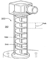
図1は、気液混合物の液体と気体を分離するため液体触媒燃料電池で使用する、螺旋チャンネル100の螺旋150の略図である。図1aは螺旋150の側面図であり、図1bは螺旋150の斜視図である。
FIG. 1 is a schematic diagram of a
螺旋150は、螺旋軸102(z)、螺旋ピッチ104(PHelix)、および直径106を有する。気液混合物は、螺旋チャンネルの投入端108でチャンネルに投入され、螺旋チャンネル100の排出端110に向かって螺旋150の方向に螺旋チャンネルに沿って進むように拘束される。
The
図に示される螺旋150の画像が螺旋チャンネルの中心線を表すこと、およびPHelixの寸法は、長手方向(螺旋軸102に平行)に隣接する螺旋領域の間の螺旋チャンネルの壁の厚さを考慮する必要があることは、注目に値する。すなわち、PHelixは、螺旋チャンネルの1つの領域の頂部からその上に隣接する領域の頂部、または螺旋チャンネルの1つの領域の底部からその下に隣接する領域の底部を測定するべきである。このことは、下でさらに記載されることになる図2を手短に参照することによりさらに容易に理解することができる。
The image of
図2に示されるように、明らかに、螺旋チャンネルは、螺旋チャンネルに沿った任意の1点で、水力直径すなわち断面チャンネル幅またはチャンネル直径(DPipe)を有する。例えば、チャンネルが円形セクションパイプにより規定される場合、チャンネル直径は、パイプの直径(DPipe)であり、一方矩形セクションパイプは、矩形セクションの水力直径に等しいチャンネル直径DPipeを有することになる。 Clearly, as shown in FIG. 2, the helical channel has a hydraulic diameter or cross-sectional channel width or channel diameter (D Pipe ) at any one point along the helical channel. For example, if the channel is defined by a circular section pipe, the channel diameter is the pipe diameter (D Pipe ), while the rectangular section pipe will have a channel diameter D Pipe equal to the hydraulic diameter of the rectangular section.
コンピュータによる流体力学の使用によって、無次元の直径比パラメータ(λ)の最適値を示す結果が得られた。このパラメータは、螺旋チャンネルの全体的な横軸直径または螺旋直径(DHelix)と、チャンネル上の任意の1点における螺旋チャンネルの断面の水力直径(DPipe)の間の比である(λ=DHelix/DPipe)。 The use of computational fluid dynamics has resulted in an optimal value for the dimensionless diameter ratio parameter (λ). This parameter is the ratio between the overall transverse or spiral diameter (D Helix ) of the helical channel and the hydraulic diameter (D Pipe ) of the cross section of the helical channel at any one point on the channel (λ = D Helix / D Pipe ).
下で説明されるように、λの最適値が、動作パラメータの選択された組についての、最大修正ディーン数(Dm)をもたらした。 As explained below, the optimal value of λ resulted in the maximum modified Dean number (Dm) for the selected set of operating parameters.
ディーン数(Dn)は、2次流(遠心力に対する慣性)の測定値であり、Dmは、適切な螺旋の幾何学的要因を考慮に入れている。 Dean number (Dn) is a measure of secondary flow (inertia to centrifugal force), and Dm takes into account the appropriate helical geometric factors.
説明として、最大分離は、理論では、各相の密度の違いによって、最大Dmで起こるはずである。
修正ディーン数は以下により与えられる。
Dm=Re√(κDpipe/2)
ここで、螺旋の曲率は以下により与えられる。
κ=(DHelix/2)/[(DHelix/2)^2+(PHelix/2π)^2]
上式で、PHelixは、前の領域の底部から次の領域の底部の垂直距離(すなわち、DPipe+螺旋領域の厚さ)として規定され、2相流れについてのレイノルド数(Re)は、以下により与えられる。
Re=(ρmixVmixDpipe)/μmix
上式で、μmix(気液混合物の粘度)およびρmix(気液混合物の密度)は以下により与えられる。
μmix=εμGas+(1−ε)μLiq
および
ρmix=ερGas+(1−ε)ρLiq
それぞれで、εは気体体積画分であり、ρmixは気液混合物の密度であり、Vmixは気液混合物の速度であり、μmixは気液混合物の粘度であり、μGas、μLiq、ρGas、およびρLiqは、気体および液体それぞれの粘度および密度である。気体体積画分εは以下で与えられる。
ε=QGas/(QGas+QLiq)
上式で、QGasおよびQLiqは、気体および液体それぞれの流量である。
As an illustration, maximum separation should theoretically occur at maximum Dm due to the difference in density of each phase.
The modified Dean number is given by
Dm = Re√ (κD pipe / 2)
Here, the curvature of the helix is given by:
κ = (D Helix / 2) / [(D Helix / 2) ^ 2 + (P Helix / 2π) ^ 2]
Where P Helix is defined as the vertical distance from the bottom of the previous region to the bottom of the next region (ie, D Pipe + the thickness of the spiral region), and the Reynolds number (Re) for a two-phase flow is Is given by:
Re = (ρ mix V mix D pipe ) / μ mix
Where μ mix (viscosity of gas-liquid mixture) and ρ mix (density of gas-liquid mixture) are given by:
μ mix = εμ Gas + (1-ε) μ Liq
And ρ mix = ερ Gas + (1-ε) ρ Liq
Where ε is the gas volume fraction, ρ mix is the density of the gas-liquid mixture, V mix is the velocity of the gas-liquid mixture, μ mix is the viscosity of the gas-liquid mixture, μ Gas , μ Liq , Ρ Gas , and ρ Liq are the viscosity and density of the gas and liquid, respectively. The gas volume fraction ε is given by:
ε = Q Gas / (Q Gas + Q Liq )
In the above equation, Q Gas and Q Liq are the flow rates of gas and liquid, respectively.
乱流では、遠心力は慣性力により支配され、したがって二次的効果が減少する。このことが、螺旋パイプ中の乱流の開発が遅れたことの原因になる(Mandal, S.N.およびDas, S.K著、「Gas−Liquid Flow through Helical Coils in Vertical Orientation」、Industrial & Engineering Chemistry Research 42、3487〜3494、2003年)。 In turbulent flow, centrifugal force is dominated by inertial forces, thus reducing secondary effects. This causes a delay in the development of turbulent flow in helical pipes (Mandal, SN and Das, SK, “Gas-Liquid Flow through Helical Coil in Vertical Orientation”, Industrial & Engineering Chemistry Research 42, 3487-3494, 2003).
最初のモデル化の研究は、本発明者により実施され、そこではPHelixは、チャンネルまたはパイプ直径より1.3倍大きいものとして固定された。
PHelix=1.3*Dpipe
Initial modeling studies were performed by the inventor, where P Helix was fixed as 1.3 times larger than the channel or pipe diameter.
P Helix = 1.3 * D pipe
製造上の制約(すなわち、パイプ壁の厚さ)がこの比を制限したことに留意されたい。したがって、自由な変数は、流量および直径比λであった。液体および気体の流量は、実際の動作値に制約された。すなわち、液体流量(QLiq)は、毎分3〜30リットル(L/min)であるように選択され、気体流量(QGas)は、毎分12〜120リットル(L/min)であるように選択された。直径比λは0〜1000に変えられ、Dmが出力とされた。この研究の結果は、無次元ピッチパラメータ(H)が1に近づくときにλの最適値が生じることを示唆した。ここで、
H=PHelix/(2πRHelix)
上式で、
RHelix=DHelix/2
である。
Note that manufacturing constraints (ie, pipe wall thickness) limited this ratio. Therefore, the free variables were flow rate and diameter ratio λ. Liquid and gas flow rates were constrained to actual operating values. That is, the liquid flow rate (Q Liq ) is selected to be 3-30 liters per minute (L / min), and the gas flow rate (Q Gas ) seems to be 12-120 liters per minute (L / min). Selected. The diameter ratio λ was changed to 0 to 1000, and Dm was output. The results of this study suggested that the optimum value of λ occurs when the dimensionless pitch parameter (H) approaches 1. here,
H = P Helix / (2πR Helix )
Where
R Helix = D Helix / 2
It is.
すなわちこの結果は、螺旋ピッチPHelixが、全体的な螺旋直径DHelixのπ倍に等しいとき、すなわち以下であるときに、λの最適値が生じることを示唆した。
最適PHelix=πDHelix
このことによって、最大修正ディーン数が得られる結果となった。
That is, this result suggested that the optimum value of λ occurs when the helical pitch P Helix is equal to π times the overall helical diameter D Helix , ie,
Optimal P Helix = πD Helix
This resulted in a maximum modified Dean number.
無次元ピッチパラメータHの異なる値について、修正ディーン数Dmの変化が表される実験が実施された。上で示唆されたように、Hが1に近づくとDmが最大であることが見出された。このことは、物理的に不可能であるが、直径比λの最適値が1/πであることに対応する。 For different values of the dimensionless pitch parameter H, an experiment was performed in which the change in the modified Dean number Dm was represented. As suggested above, Dm was found to be maximal as H approaches 1. This is physically impossible, but corresponds to the optimal value of the diameter ratio λ being 1 / π.
これらの結果から、Dmの値が、λの異なる値について計算された。λの最適値は、Dmの最大値をもたらす。(無次元ピッチパラメータHを最適化することに加えて)最大Dm用にλを最適化することによって、完全に規定されたシステムが実現される。 From these results, the value of Dm was calculated for different values of λ. The optimal value of λ results in the maximum value of Dm. By optimizing λ for maximum Dm (in addition to optimizing the dimensionless pitch parameter H), a fully defined system is realized.
上から理解することができるように、螺旋形状の中の流れを支配する数学的関係の結論は、螺旋直径がパイプ直径よりも小さい(最適λが1/πである)ときに、最大Dmが、所与の直径のパイプ内で生じることを意味する。しかし、全体的な螺旋直径DHelixは、パイプ直径DPipeの2倍未満であることはできないので(例えば、下に記載される図2を参照)、明らかに、そのようなλの理論的な最適値は物理的に不可能である。このことは、λが2以上であるように制限されることを意味する。実際には、λは、螺旋チャンネルの壁の厚さがゼロでないことのために、2よりも大きくならなければならない。 As can be seen from the above, the conclusion of the mathematical relationship governing the flow in the helical shape is that when the helical diameter is smaller than the pipe diameter (optimal λ is 1 / π), the maximum Dm is , Means occurring within a pipe of a given diameter. However, since the overall helical diameter D Helix cannot be less than twice the pipe diameter D Pipe (see, eg, FIG. 2 described below), clearly such a theoretical λ The optimum value is physically impossible. This means that λ is limited to be 2 or more. In practice, λ must be greater than 2 because the wall thickness of the helical channel is not zero.
したがって、λの最良の物理的に実現可能な値は、Dmの最大値を達成するため、2よりもわずかに大きく、すなわち、できるだけ2に近い。 Thus, the best physically feasible value of λ is slightly larger than 2, ie as close to 2 as possible, in order to achieve the maximum value of Dm.
したがって好ましくは、好ましい実施形態によれば、任意の1点におけるDHelixおよびDPipeは、全体的な螺旋チャンネル直径DHelixが物理的に達成可能であり、できるだけ2*DPipeに近いように構成される。 Thus, preferably, according to a preferred embodiment, D Helix and D Pipe at any one point are configured such that the overall helical channel diameter D Helix is physically achievable and is as close to 2 * D Pipe as possible. Is done.
図2は、完全な流れにおいて電解質液体と気体(空気)を分離するために首尾よく使用された、螺旋チャンネルを備える螺旋分離器の部分透過斜視図である。この構成中で、結果として生じる圧力低下は、同様のサイズの知られているGLCC設計で生じる圧力低下の12.5%未満であり、したがって、液体と気体の大量の分離を実施する。 FIG. 2 is a partially transparent perspective view of a helical separator with helical channels that has been successfully used to separate electrolyte liquid and gas (air) in a complete flow. In this configuration, the resulting pressure drop is less than 12.5% of the pressure drop that occurs with similarly sized known GLCC designs, thus performing a large separation of liquid and gas.
図2の装置により大量の分離が実施された後、いくつかの靄粒子が、排出領域の空気流に見られる。さらに、分離器を出る空気が蒸気相の液体で飽和していることが知られている。 After a large amount of separation has been performed by the apparatus of FIG. 2, some soot particles are found in the air flow in the discharge area. Furthermore, it is known that the air leaving the separator is saturated with a vapor phase liquid.
図2の分離器は、気体と液体を分離することに効率的であるが、気相と液相を分離した際であっても、液体の比較的大部分は、液体の蒸気相に捕捉される。これは、FlowCath(商標)システムの動作状態、すなわち、気液接触の動作状態およびこの気液接触動作が実行されるのが比較的高温であることに起因する。このことは、この技術の可能な応用分野が、熱移動の応用分野であることを表す(下で議論される図3a、図3bを参照)。 The separator of FIG. 2 is efficient in separating gas and liquid, but even when the gas phase and liquid phase are separated, a relatively large portion of the liquid is trapped in the liquid vapor phase. The This is due to the operating state of the FlowCath ™ system, that is, the operating state of gas-liquid contact and the fact that this gas-liquid contact operation is performed at a relatively high temperature. This indicates that a possible application area of this technology is that of heat transfer (see FIGS. 3a and 3b discussed below).
気体からの蒸気相の液体の分離は、知られている空気−空気熱交換技術により実施することができる。しかし、空気−空気熱交換器は、工業規模では比較的効率的であるが、FlowCath(商標)システムの既存のサイズおよび電力の制約を有する、少なくとも1つの知られている正味1kWの定常状態システムでは、濃度を制御するために十分な液体を蒸気相から凝縮しない。この制限が、解決するべき問題を表している。 Separation of the vapor phase liquid from the gas can be accomplished by known air-air heat exchange techniques. However, the air-air heat exchanger is relatively efficient on an industrial scale, but has the existing size and power constraints of the FlowCath ™ system, at least one known net 1 kW steady state system. Does not condense enough liquid from the vapor phase to control the concentration. This limitation represents a problem to be solved.
液体のより良好な蒸気相除去を達成する2つの方法は、(a)熱交換器の表面積の増加、および(b)熱交換器を通る冷たい空気流の増加である。しかし、これらの方法は、それぞれ、大きなパッケージ体積および大きな寄生負荷のために、最適ではない。したがって、依然として問題が存在する。 Two ways to achieve better vapor phase removal of the liquid are (a) increasing the surface area of the heat exchanger and (b) increasing the flow of cold air through the heat exchanger. However, these methods are not optimal because of the large package volume and large parasitic load, respectively. Thus, there are still problems.
上の問題および制限に対処するための試みで、(第1の螺旋分離器と同じ寸法の)第2の螺旋分離器が、任意の飛散された液相の小滴を除去し、電解質の並外れて良好な分離を行わせ、水のいくらかの予備的な凝縮もする、非常に効率的な場合があることが見出された。 In an attempt to address the above problems and limitations, a second spiral separator (same size as the first spiral separator) removes any splashed liquid phase droplets, resulting in an extraordinary electrolyte. It has been found that it can be very efficient, providing good separation and some precondensation of water.
加えて、螺旋分離器の好ましく想定される構成では、冷気流および(蒸気相で水分が多い)熱気流が、螺旋流路内の金属(例えば鉄鋼)筐体により隔離される。 In addition, in the preferred conceivable configuration of the spiral separator, the cold air stream and the hot air stream (in the vapor phase and high in moisture) are isolated by a metal (eg steel) housing in the spiral channel.
第1の螺旋チャンネル(例えば、図2の螺旋チャンネル200)が、気液混合物の液体と気体を分離して、(a)まだ液相である大量の液体、(b)蒸気相の液体で飽和した気相、および(c)靄の形態で気相中に飛散された液相を生成する。第2の螺旋チャンネル(例えば、下で議論される、図3aまたは図3bの螺旋チャンネル302)が、次いで、飽和した気相および液相の小滴を、気体と液相の液体に分離する。
A first helical channel (eg,
螺旋チャンネルの曲がった形状内の2次流が、層流にとってより影響が大きい熱移動係数を増加させる。現在のFlowCath(商標)システム(および近い将来のもの)についての流れの型は、空気プレート凝縮器について層状となる。囲まれた螺旋チャンネル内にまたはその部分として、熱交換器のプレートまたはフィンを閉じ込めることが、熱移動係数を(約2倍に)増加させる結果、蒸気相の液体と気体の分離を向上させる役割を果たすことが見出された。このことが、凝縮器の表面積を半分にし、一方、依然として同じ量の分離に影響を及ぼすことを可能にする。 The secondary flow within the curved shape of the helical channel increases the heat transfer coefficient, which is more influential for laminar flow. The flow type for the current FlowCath ™ system (and the near future) is layered for the air plate condenser. Confinement of heat exchanger plates or fins within or as part of the enclosed spiral channel plays a role in improving the separation of vapor phase liquid and gas as a result of increasing the heat transfer coefficient (about twice) Has been found to fulfill This makes it possible to halve the surface area of the condenser while still affecting the same amount of separation.
続けて、本発明の態様は、燃料電池システムの液体電解質再生器のための分離器を提供し、螺旋上に形成されたパイプの形態の螺旋チャンネルを備え、気液混合物を伝導して気液混合物から液体を分離するように構成されており、分離器の螺旋チャンネルが、気液混合物がそれに沿って進むように拘束される、囲まれたチャンネルである。螺旋チャンネルは、冷却される流体を伝導するための熱交換器(例えば、空気−空気プレート凝縮器またはより密度の高い流体用の向流管形交換器)として使用することができる。そのような熱交換器は、流体の凝縮を実施するように、蒸気相の流体を伝導し冷却するのに特に有用である。 Continuing, an aspect of the present invention provides a separator for a liquid electrolyte regenerator of a fuel cell system, comprising a helical channel in the form of a pipe formed on a helix, conducting a gas-liquid mixture to conduct a gas-liquid mixture A spiral channel of the separator, which is configured to separate liquid from the mixture, is an enclosed channel that is constrained to travel along the gas-liquid mixture. The spiral channel can be used as a heat exchanger (eg, an air-air plate condenser or a counter-current tube exchanger for denser fluids) to conduct the cooled fluid. Such heat exchangers are particularly useful for conducting and cooling vapor phase fluids so as to effect fluid condensation.
図3aは、凝縮器として使用するためにこの原理を採用している、新規の螺旋空気プレート熱交換器300の、提案される構成の斜視図である。熱交換器300は、6つの囲まれた螺旋チャンネル302、304、306、308、310、312(5つのチャンネルは冷却空気用、残りのチャンネルは熱く、蒸気が濃い空気用に使用される)を備える。
FIG. 3a is a perspective view of the proposed configuration of a novel spiral air
図3bは、図3aに示された熱交換器300の端部の、部分破断図である。螺旋チャンネル302、304などは、より明瞭に理解することができる。隣接する(冷たい空気の)螺旋チャンネル間に、間隙320が存在し、間隙320の中で、熱く、蒸気が濃い空気などの流体が、各螺旋チャンネルの外側表面310、312を通り過ぎることができる。理解できるように、本実施形態の螺旋チャンネルは、中空のフィンの形態である。この場合、「螺旋チャンネル」は、複数の中空のフィンを備える。中空の構造によって、螺旋チャンネルの外側表面上を流れるが、螺旋チャンネル内の気液混合物と混合しない、冷却流体(例えば、空気)を、分離して供給することが可能になる。
FIG. 3b is a partial cutaway view of the end of the
現在採用されている、既製品の空気−空気プレート凝縮器は、約0.8m2の全表面積を有する(UK Heat Exchangers(商標))。対照的に、図3aおよび図3bに示される熱交換器は、熱移動係数が2倍に増加することにより可能になった、0.431m2の全低温表面積を有しており、このことによって、所与のPEM燃料電池システムで使用される凝縮器の全体サイズを著しく減少させることが可能になる。 Currently used off-the-shelf air-air plate condensers have a total surface area of about 0.8 m 2 (UK Heat Exchangers ™). In contrast, the heat exchanger shown in FIGS. 3a and 3b has a total cold surface area of 0.431 m 2 , which is made possible by a two-fold increase in the coefficient of heat transfer. The overall size of the condenser used in a given PEM fuel cell system can be significantly reduced.
熱交換器の螺旋チャンネルのフィンまたは冷却表面の表面積を増加させること、例えば冷却表面(図3bの310、312)を波形にすることおよび/またはディンプル加工することによって滑らかでない冷却表面を設けることにより、パッケージ体積を増加させる必要なく、熱交換器をさらに改善することができる。 By increasing the surface area of the fin or cooling surface of the helical channel of the heat exchanger, for example by providing a non-smooth cooling surface by corrugating and / or dimple processing the cooling surface (310, 312 in FIG. 3b) The heat exchanger can be further improved without having to increase the package volume.
フィンまたは冷却表面が低表面エネルギー材料(例えば、PTFE)を含む表面を備えるように、フィンまたは冷却表面を構成することにより、分離をさらに改善することができる。高度に疎水性の材料は、デウェット力を利用し、台形境界を離れさせ、それによって、台形境界により分離される2つの気泡であるよりも単一の気泡を形成するほうがエネルギー的に好都合になることによって、合体を生じさせることができる。 Separation can be further improved by configuring the fin or cooling surface such that the fin or cooling surface comprises a surface comprising a low surface energy material (eg, PTFE). Highly hydrophobic materials take advantage of the dewetting force to leave the trapezoidal boundary, thereby making it more energetically favorable to form a single bubble than two bubbles separated by a trapezoidal boundary As a result, coalescence can be produced.
一実施形態によれば、図3bに示された閉じたセクションが開のままとされることが例外ではあるものの、それぞれ図2および図3に示された螺旋の組合せが設けられる。この実施形態では、気液混合物は、図2について上に記載されたように螺旋に入る。しかし、流体通路は、主螺旋領域に平行に延びる領域を有するいくつかの「フィン」を収容する。これらのフィン、螺旋管の壁、および主螺旋領域は、低表面エネルギー材料でコーティングされることになる。図2に示した実施形態について上に記載したように、フィンの直径は、主螺旋直径よりもわずかに小さく、螺旋流の発生を可能にすることになる。 According to one embodiment, with the exception that the closed section shown in FIG. 3b is left open, a combination of the spirals shown in FIGS. 2 and 3, respectively, is provided. In this embodiment, the gas-liquid mixture enters the helix as described above for FIG. However, the fluid passage contains several “fins” having regions extending parallel to the main spiral region. These fins, the walls of the helical tube, and the main helical region will be coated with a low surface energy material. As described above for the embodiment shown in FIG. 2, the fin diameter is slightly smaller than the main helix diameter, which will allow the generation of helical flow.
上に記載した低表面エネルギーフィンは、螺旋内の全体的な流体流に大きく影響することはないが、内部表面積/摩擦効果が増加することに起因して、単位長当たりに追加の圧力低下があることになる。しかし、これらの低表面エネルギーフィンは、気液分離が影響を受ける比率を増加させ、したがってより短い全体長の螺旋を必要とすることになるので、全体として圧力低下が増加することは起こらない可能性がある。この実施形態は、デバイスの全体サイズを減少させる一方、効率的な分離を維持することを可能にする。 The low surface energy fins described above do not significantly affect the overall fluid flow within the helix, but there is an additional pressure drop per unit length due to the increased internal surface area / friction effect. There will be. However, these low surface energy fins increase the rate at which gas-liquid separation is affected, and therefore require a shorter overall length helix, so the overall pressure drop may not increase. There is sex. This embodiment makes it possible to maintain an efficient separation while reducing the overall size of the device.
図4aは、入口により大きな螺旋直径、出口により小さな螺旋直径を有する先細螺旋チャンネル400の流体通路の斜視図である。気液混合物は入口に入る。次いで、分離された気体が螺旋の内部コア内の気体排気口を通って徐々に出て(図4b)、最小量の空気が、流体出口を通って出、したがってパイプ流に近づいて、自由表面流から遠ざかる。螺旋途中で空気を排気することは、Rosaらにより提案された(Rosa、E著、Journal of Petroleum Science and Engineering 32、87〜101、2001年、およびOAPI特許出願公開第OA11321(A)号)。しかし、Rosaは、上に記載し、図4および図5に示された、徐々に増加する螺旋直径および徐々に増加するパイプ直径を有する実施形態とは異なり、一定の螺旋直径を有する構成を開示している。
FIG. 4a is a perspective view of the fluid path of a tapered
図4aおよび図4bに示された実施形態は、図2に示された設計についての改善を提供する。流体が出口に向かって下向きに進むにつれて直径が減少するパイプを使用することによって、連続方程式にしたがって速度が増加する結果となる。付随して、気液混合物に作用する有効重力が増加することになる。 The embodiment shown in FIGS. 4a and 4b provides an improvement over the design shown in FIG. Using a pipe that decreases in diameter as the fluid progresses downward toward the outlet results in an increase in velocity according to the continuity equation. Concomitantly, the effective gravity acting on the gas-liquid mixture will increase.
気体対液体の比率が高い場合であっても、密度の差が非常に大きいので、気液混合物の運動量に対する気体の寄与はわずかである。したがって、完全な分離が達成されたときであっても、流体は、気液混合物として螺旋に入ったときに流体が有していた運動量の大部分を維持する。流体が出口に向かって進むにつれてパイプ直径が減少することによって、液体の速度が増加することになる。流体速度が増加し、回転半径が減少することの結果として、気液混合物に作用する有効重力は、一定の断面の螺旋分離器と比較して劇的に増加する。 Even when the ratio of gas to liquid is high, the difference in density is so great that the contribution of the gas to the momentum of the gas-liquid mixture is small. Thus, even when complete separation is achieved, the fluid retains most of the momentum it had when entering the helix as a gas-liquid mixture. By reducing the pipe diameter as the fluid travels toward the outlet, the velocity of the liquid will increase. As a result of increasing fluid velocity and decreasing radius of rotation, the effective gravity acting on the gas-liquid mixture increases dramatically compared to a constant-section helical separator.
例えば、気液混合物の同じ流量および組成物を使用して、一定の断面(図2)上に加わる有効重力は10g(すなわち、重力の10倍、つまり、98.1m/s2)であり、一方、図3aおよび図3bに示された先細螺旋に加わる有効重力は10gで始まり、はるかに高い最大値の21gに到達する。
For example, using the same flow rate and composition of the gas-liquid mixture, the effective gravity applied on a constant cross-section (FIG. 2) is 10 g (
図5は、図4aに示された先細螺旋チャンネル400を規定するために使用することができる、内部装置500の内部斜視図である。内部装置500は、螺旋羽根501および羽根501に取り付けられる内部壁502を有しており、内部壁502は、その中に1つまたは複数の気体排気口503を有して、気体が、流体出口に再度入ることを防ぐため、垂直にまたは部分的に垂直に出ることを可能にすることができる。この構成は、液体が多い材料がチャンネルの中で形成する「スラグ」により生じる可能性がある、脈動流を無効にする役割を果たす。この構成は、チャンネルの全体的なサイズを減少させ、自由表面流から離れて、最も重要なことに、分離効率を増加させる役割も果たす。螺旋チャンネル400(図4a)は、装置500の螺旋羽根501に隣接して取り囲む外壁(図示せず)を備える。
FIG. 5 is an internal perspective view of an
気体排気口503は、微孔性膜503を備えることができ、微孔性膜503は、螺旋チャンネル400の内壁502の全部または一部を形成して、気体が早く逃げることを可能にし、膜の疎水性の性質に起因して液体が逃げることを防止することができる。気体排気口503は、少なくとも部分的には気体排気口503の直径が小さいことに起因して、気体排気口503を通って液体が通過することを抑制するように構成される。
The
螺旋チャンネル400(図4a)は、螺旋チャンネル400の外壁内に組み込まれる、多孔質の気泡生成エレメント504(図4aには図示せず)を備えることができる。多孔質の気泡生成エレメント504の位置決めは、気体と液体の間に既に存在する密度の差、ならびに、螺旋チャンネル400の中の螺旋流路の結果として加わる遠心性の重力を利用しており、外壁から内壁502に気体を迅速に確実に移動させる。この構成によって、質量移動および反応(反応物が多く集中すること)のため、最大の駆動力の結果として、気体と液体の間の最大の質量移動速度(このシステムでは反応速度に対応する)が可能になる。
The helical channel 400 (FIG. 4a) may comprise a porous bubble generating element 504 (not shown in FIG. 4a) that is incorporated into the outer wall of the
加えて、この構成によって、単一の空気注入点を使用することによっては可能ではなかった、全体として非常に高い気体と液体の比率を達成することが可能になる。 In addition, this configuration makes it possible to achieve a very high overall gas to liquid ratio, which was not possible by using a single air injection point.
多孔質の気泡生成エレメント504は、気体と液体の接触を同時に実施するために使用することができ、一方、多孔質エレメントの後の螺旋の巻き(領域)は、分離のために使用することができる。多孔質エレメント504は、図5には複数の開口または排気口として示されるが、同様に微孔性膜であってよい。多孔質エレメント504は、螺旋チャンネルが、分離器として、かつ再生器としての両方で動作することを可能にする。気体排気口503および多孔質エレメント504は、先細でないまたは徐々に増加しない、すなわち一定の螺旋直径を有する螺旋チャンネルとともに使用できることを理解されたい。
The porous
多孔質エレメントまたは隙間の使用によって、気液接触および気液分離の2重の機能のため、より容量効率的な螺旋形状を可能にすることができる。 The use of porous elements or gaps can allow a more volumetric efficient spiral shape due to the dual function of gas-liquid contact and gas-liquid separation.
螺旋流デバイスは、熱移動の応用分野で広く使用されている。しかし、螺旋流は、液体触媒燃料電池システムでは使用されてこなかった。そのような液体触媒燃料電池システムは、泡の破壊または高い気体と液体の比率を有する小滴流の分離についてのいかなる機能も含まなかった。微孔性膜を使用して、螺旋チャンネルから空気/気体を排気し、気液混合物の分離を達成することは、新規である。 Spiral flow devices are widely used in heat transfer applications. However, spiral flow has not been used in liquid catalytic fuel cell systems. Such a liquid catalyst fuel cell system did not include any function for bubble breakage or separation of droplet streams having a high gas to liquid ratio. It is novel to use a microporous membrane to evacuate air / gas from the spiral channel and achieve gas-liquid mixture separation.
図6は、液体電解質燃料電池システム600を示す。このシステムでは、液体酸化還元カソード電解質(カソード液)が燃料電池スタック602を循環し、燃料電池スタック602の中の燃料電池604の作用に起因して、液体酸化還元カソード電解質(カソード液)は燃料電池スタック602の中で還元される。液体酸化還元カソード液は、次いで再生器606を通過し、再生器606の中でカソード液が酸化する。
FIG. 6 shows a liquid electrolyte
酸化プロセスは、液体カソード液と大量の空気の接触を必要とし、液体と空気は、標準温度および圧力(STP)で、4:1よりも大きい、理想的には20:1以上までの、重量ベースの空気と液体の比である。液体と気体/空気との間の界面は、気泡膜または膜の形態で生成される。気体/空気からカソード液の中への酸素の質量移動を最大にするために、これらの気液界面の全面積を最大にすることが望ましい。 The oxidation process requires contact between the liquid catholyte and a large amount of air, where the liquid and air are greater than 4: 1 and ideally up to 20: 1 or more by weight at standard temperature and pressure (STP). The ratio of base air to liquid. The interface between liquid and gas / air is created in the form of a bubble film or film. In order to maximize the mass transfer of oxygen from the gas / air into the catholyte, it is desirable to maximize the total area of these gas-liquid interfaces.
再生器の中の気液界面は、小さな気泡半径を有する気泡を含む、大内部相体積の泡の形態である。液体カソード液の再生(酸化)の速度は、気液界面の全界面面積に比例する。燃料電池システム600の典型的な使用について、有用な量の電力を燃料電池スタックが生成することができるように、高速の再生が要求される。
The gas-liquid interface in the regenerator is in the form of a large internal phase volume of bubbles, including bubbles with a small bubble radius. The rate of regeneration (oxidation) of the liquid catholyte is proportional to the total interface area of the gas-liquid interface. For typical use of the
再生された電解質、および電解質と混合された気体は、次いで、螺旋分離器(図2の200)を備える、気液分離器608の中に一緒に伝導される。分離器608は、出力として、(a)大量の液体電解質、および(b)小滴/靄および/または蒸気相の液体の形態の液体電解質と混合した気体(空気)を含む密度の低い気液混合物を提供する。混合物の中の液体を液相の大量の液体の形態で集めるために、より密度の高い液体が、貯蔵器610に(この例では重力により)供給される。分離器が気体を排出し、気体は、この例では図3aおよび図3bに示される凝縮器(図3aおよび図3bの300)、凝縮器612の中に伝導される。冷却ファン614によって、凝縮器612の冷却フィン上を、外部冷却空気が通過する。流体ポンプ616は、貯蔵器610により集められた液体をポンピングし、燃料電池スタック602の燃料電池604の中の電解質として使用するために、液体を燃料電池スタック602に出力する。凝縮器612は、貯蔵器610に凝縮した液体(凝縮液)を、液相の液体の形態で排出する。
The regenerated electrolyte and the gas mixed with the electrolyte are then conducted together into a gas-
再生器606に再び戻って、液体電解質(カソード液)が一度再生されたら、残留気体(主に窒素)は、それぞれの燃料電池604のカソードに供給され、気泡を含むべきでないカソード液から除去されなければならい。なぜならば、そのような気泡は、燃料電池604の動作に干渉するからである。残留または「使用済み」気体を係脱または分離することが、迅速に、効率的に、かつ最小の電力消費で実施されることが極めて望ましい。
Returning again to the
ハイドロサイクロンおよび遠心器などの機械的分離法は、容認しがたい量の電力を使用する。螺旋分離器608は、より小さい電力を必要とする、代替の機械分離を実現することができる。しかし、減少した電力、およびより小さい物理的な体積で分離効率を改善するという要求が常に存在する。したがって、これまで、上に記載された機械的分離法の他に、または加えて、分離法を採用することが望ましい。
Mechanical separation methods such as hydrocyclones and centrifuges use unacceptable amounts of power. The
国際特許出願公開第WO2010/108227号は、疎水性粒子の乾式分離のための方法および装置を開示する。しかし、第WO2010/108227号は、粒子分離を対象とし、気液界面の破裂を対象としておらず、燃料電池に関していない。独国特許公開第DE10323155A1号は、気体流から小滴またはエアロゾル形態の液体を除去するための分離器を開示する。しかし、第DE10323155A1号は、泡または燃料電池に関係しない。
International Patent Application Publication No. WO 2010/108227 discloses a method and apparatus for dry separation of hydrophobic particles. However, WO2010 / 108227 is intended for particle separation, not for gas-liquid interface rupture, and is not related to fuel cells.
参照により本明細書に組み込まれる、日本国特許公開第JP3038231号は、親水性要素および疎水性要素から構成される分離ユニット膜を開示する。参照により本明細書に組み込まれる、日本国特許公開第JP1297122号は、気体分離のための液体膜として使用される疎水性孔のみから構成される膜を有し、積層形態で保持されるキャリアを含む液体の薄膜からなる材料を開示する。 Japanese Patent Publication No. JP3038231, which is incorporated herein by reference, discloses a separation unit membrane composed of a hydrophilic element and a hydrophobic element. Japanese Patent Publication No. JP 1297122, which is incorporated herein by reference, includes a carrier that is comprised of only hydrophobic pores that are used as a liquid membrane for gas separation and that is held in a laminated form. A material comprising a liquid thin film is disclosed.
泡の中の液体と気体の分離が、以前に調査された。例えば、参照により本明細書に組み込まれる、P.R. Garrett著「Defoaming: Theory and Industrial Applications」、CRC Press、ISBN 0−8247−8770−6を参照のこと。参照により本明細書に組み込まれる、D. Weaire & S. Hutzler著、「The Physics of Foams」、Clarendon Press、ISBN 0−19−851097−7、頁149〜150も参照のこと。参照により本明細書に組み込まれる、P.R. Garrett, S.P. Wicks, E. Fowler著、「The effect of high volume fraction of latex particles on foaming and antifoam action in surfactant solutions」Colloids and Surfaces A、Physicochem. Eng. Aspects 282〜283 (2006年) 307〜328もある。 The separation of liquid and gas in the foam was previously investigated. See, for example, P.I., which is incorporated herein by reference. R. See Garrett, “Defoaming: Theory and Industrial Applications”, CRC Press, ISBN 0-8247-8770-6. D., which is incorporated herein by reference. Weair & S. See also Hutzler, "The Physics of Forms", Clarendon Press, ISBN 0-19-851097-7, pages 149-150. P., incorporated herein by reference. R. Garrett, S.M. P. Wicks, E.W. Fowler, “The effect of high volume fraction of latex particles on foaming and antifacting actions in surficial solutions. Eng. Aspects 282-283 (2006) 307-328 are also available.
液体膜および気泡の破裂における、いわゆる「消泡剤」の作用はよく知られている。消泡剤が泡の気液界面を破裂することができる様々な仕組みが存在しており、仕組みは、消泡剤の製剤法および剤形に依存するが、そのような仕組みは一般に、液体膜と低表面エネルギー表面との間の相互作用についての以下の説明によって記載することができる。この作用は、いわゆる「デウェット」をもたらす。デウェットは、基板(液体または固体のいずれか)上の薄い液体膜の破れおよび小滴の形成のことを言う。反対のプロセス(基板上の液体の広がり)は「スプレッド(spreading)」と呼ばれる。 The action of so-called “antifoaming agents” in the rupture of liquid films and bubbles is well known. There are various mechanisms by which antifoams can rupture the gas-liquid interface of the foam, and the mechanism depends on the formulation and dosage form of the antifoam, but such mechanisms are generally liquid films And the following description of the interaction between the low surface energy surface. This action results in so-called “dewetting”. Dewetting refers to the tearing of a thin liquid film and the formation of droplets on a substrate (either liquid or solid). The opposite process (spreading of the liquid on the substrate) is called “spreading”.
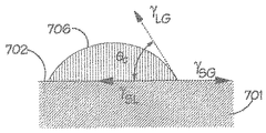
図7は、低表面エネルギーを有する表面702を有する固体物体701を示す。水滴706は低エネルギー表面702上に位置する。小滴は、図中でθcにより示される規定の接触角が、低エネルギー表面と周囲の気体/空気と接触する小滴の表面との間に対応するような位置にあることになる。
FIG. 7 shows a
角度は、下に記載するような、ヤングの式により規定される。
γSL+γLGcos(θc)=γSG
The angle is defined by Young's equation, as described below.
γ SL + γ LG cos (θ c ) = γ SG
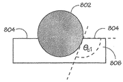
図8は、水性泡膜806の気液界面804における、低表面エネルギー、疎水性粒子802を示す。
FIG. 8 shows low surface energy,
図9は、図8に示した疎水性粒子802および気液界面804の拡大図を示す。粒子は、膜表面と粒子表面との間の規定接触角が上に与えられたヤングの式を満足するように、膜806の中または膜806の上の位置にあり、角度は、図9のθc1により示される。
FIG. 9 shows an enlarged view of the
図10は、図9の液体膜の反対の表面804a、804bを貫く、図9の疎水性粒子802を示す。液体膜806の反対の表面は、2つの、それぞれ気液界面804a、804bが設けられる。示されるように粒子が膜806を貫くと、膜806の各反対の表面804a、804bから粒子が突出し、接触角が両方の気液界面において規定され、角度は、粒子の(接線方向の)表面と膜の表面804a、804bとの間にあって、図10のより低い気液界面804bについては角度がθc2により示され、角度θc1は読み取りやすくするために図10では示されていない。粒子が膜806を貫くと、液体膜806を破り、気泡が破裂し、このことによって、上で概説されたデウェット効果が達成される。疎水性、または消泡剤の粒子は、次いで膜壁または隣接する気泡の膜により提供される、次の気液界面に(例えば、重力に起因して)動き、以下同様である。
FIG. 10 shows the
上記から推定されうるように、気体−液体の泡の中に疎水性粒子の形態で消泡剤を導入することは、泡の中の気体と液体を分離し、それによって泡を分離した液体部分と気体部分に変換するのに有効である。 As can be deduced from the above, the introduction of an antifoam agent in the form of hydrophobic particles in the gas-liquid foam separates the gas and liquid in the foam, thereby separating the foam. It is effective to convert into a gas part.
しかし、液体触媒燃料電池システムでは、液体電解質の中に消泡剤粒子が存在すると、燃料電池の動作に悪影響を及ぼす可能性がある。さらには、そのような消泡剤が再生器に入る液体カソード液の中に存在する場合、再生器は気泡によって気液界面を生成して酸化を促進しており、液体電解質の中の消泡剤がそのような気泡生成を抑制することになるので、不利となる。2つの矛盾する要求が存在することが理解されよう。泡の生成のためには、消泡剤が存在しないことが最良であり、一方消泡剤は、泡の破壊に有効である。液体電解質燃料電池システムでは、泡の生成および泡の破壊の両方が要求される。 However, in liquid catalyst fuel cell systems, the presence of antifoam particles in the liquid electrolyte can adversely affect the operation of the fuel cell. Furthermore, when such an antifoaming agent is present in the liquid catholyte entering the regenerator, the regenerator creates an air-liquid interface with bubbles to promote oxidation, and the antifoam in the liquid electrolyte This is disadvantageous because the agent will suppress such bubble formation. It will be appreciated that there are two conflicting requirements. For the generation of foam, it is best that no antifoam is present, while the antifoam is effective in breaking the foam. In liquid electrolyte fuel cell systems, both bubble generation and bubble destruction are required.
実施形態は、この矛盾を回避し、さらに改善された効率で気体と液体を分離するように構成された、さらに改善された螺旋分離器を提供することを得ようとする、発明性のあるやり方を提供する。これらの実施形態によれば、螺旋分離器(例えば、図2に示される分離器(図2の200))の螺旋チャンネルは、低表面エネルギー材料を含み、気液混合物と接触するように構成された表面を備える。 Embodiments seek to avoid this contradiction and seek to provide a further improved helical separator configured to separate gases and liquids with further improved efficiency. I will provide a. According to these embodiments, the helical channel of the helical separator (eg, the separator shown in FIG. 2 (200 in FIG. 2)) comprises a low surface energy material and is configured to contact the gas-liquid mixture. With an open surface.
ここで、泡を1つまたは複数の疎水性表面に接触させることにより、泡の破裂/破壊を引き起こすことが可能であることを理解されたい。そのような表面は、単なる疎水性粒子ではなく、泡または気泡を含む気液混合物と接触する固体構造物の表面であり、このことにより、気液界面を破断させる。 It should be understood here that contacting the foam with one or more hydrophobic surfaces can cause the foam to burst / break. Such a surface is not just a hydrophobic particle, but a surface of a solid structure in contact with a gas-liquid mixture containing bubbles or bubbles, thereby breaking the gas-liquid interface.
低エネルギー表面は、例えば、約18mJ/m2の表面エネルギーを有するポリテトラフルオロエチレン(PTFE)といった、特定のポリマーの中で見出される。そのようなポリマーの表面は、泡を破潰するのに非常に効率的に使用されてきた。 Low energy surfaces are found among certain polymers, such as, for example, polytetrafluoroethylene (PTFE) having a surface energy of about 18 mJ / m 2 . Such polymer surfaces have been used very efficiently to break up bubbles.
実施形態によれば、電解質の泡および低表面エネルギー材料は、(一方および/または他方が動いて)互いに隣接して動かすことができる。泡は、低表面エネルギー材料の平面または曲面に沿って単に通ることができ、または、低表面エネルギー材料がメッシュの形態をとることができ、メッシュおよび泡が相対的に、かつ互いに隣接して動くことができる。 According to embodiments, the electrolyte foam and the low surface energy material can be moved adjacent to each other (one and / or the other moving). The foam can simply pass along the plane or curved surface of the low surface energy material, or the low surface energy material can take the form of a mesh and the mesh and foam move relatively and adjacent to each other. be able to.
例えば、低表面エネルギー材料を含む、例えばメッシュといった穴あき部材を通して泡を押し通すことができる。あるいは、泡を通して穴あき部材を押し通すことができる。穴あき部材またはメッシュを使用すると、破裂界面の特定の表面積が増加する。穴のサイズは、0.1ミリメートルから10ミリメートルで変化することができ、穴あき部材は、50マイクロメートルと1ミリメートルの間の直径を有する低表面エネルギー材料(例えば、ポリマー)のフィラメントを有するメッシュを含むことができる。 For example, the foam can be forced through a perforated member, such as a mesh, including a low surface energy material. Alternatively, the perforated member can be pushed through the foam. The use of a perforated member or mesh increases the specific surface area of the rupture interface. The hole size can vary from 0.1 millimeters to 10 millimeters and the perforated member is a mesh having filaments of low surface energy material (eg, polymer) having a diameter between 50 micrometers and 1 millimeter. Can be included.
泡と穴あき部材が互いに隣合って通ると、泡の気液界面が破れ、気体と液体は、より濃い液相およびより薄い気体状の相に分離する。さらなる機械的分離(さらなる機械的分離は、例えばさらなる螺旋分離器により実施される)の前に実施されると、この動作は、全体的な分離を増大させる。そのようなさらなる螺旋分離器は、凝縮器(図6の612)により例示されたような凝縮器であってよい。 When the bubble and the perforated member pass next to each other, the gas-liquid interface of the bubble is broken, and the gas and liquid are separated into a thicker liquid phase and a thinner gaseous phase. If performed prior to further mechanical separation (further mechanical separation is performed, for example, by a further helical separator), this action increases the overall separation. Such additional spiral separator may be a condenser as exemplified by the condenser (612 in FIG. 6).
例えばメッシュといった穴あき部材を、液体電解質燃料電池システム内の螺旋分離器の上流または下流のいずれかに含むことによって、気相と液相の分離を増大させる。 Inclusion of a perforated member, such as a mesh, either upstream or downstream of the helical separator in the liquid electrolyte fuel cell system increases the separation of the gas phase and the liquid phase.
代わりに、または追加で、低表面エネルギー材料は、螺旋分離器内に組み込むことができ、図2、図3、および図4の螺旋分離器に関連して上で記載したように、分離器の内部表面が低表面エネルギー材料を含む。任意選択で有利なことに、穴あき部材またはメッシュは、そのような螺旋分離器の螺旋チャンネルの内側に存在することができる。 Alternatively or additionally, the low surface energy material can be incorporated into the spiral separator and, as described above in connection with the spiral separator of FIGS. 2, 3, and 4, the separator's The inner surface includes a low surface energy material. Optionally, advantageously, a perforated member or mesh can be present inside the helical channel of such a helical separator.
螺旋分離器が、粗い仕上げを有する内部表面を備えると、さらなる長所を得ることができる。好ましくは、内部表面が低表面エネルギーも有し、例えば、内部表面が低表面エネルギー材料のコーティングを備える。好ましくは、そのような粗い仕上げの粗さは、液体の泡の平均膜厚と同じ程度である寸法(例えば、平均寸法)を有する。例えば、内部表面が、泡の膜の平均厚と同様の幅を有する隆起部(バンプまたは突条)を有してよい。 Further advantages can be obtained if the spiral separator comprises an internal surface with a rough finish. Preferably, the inner surface also has a low surface energy, for example, the inner surface comprises a coating of a low surface energy material. Preferably, the roughness of such rough finish has a dimension (eg, an average dimension) that is about the same as the average film thickness of the liquid foam. For example, the inner surface may have ridges (bumps or ridges) having a width similar to the average thickness of the foam film.
低表面エネルギーを有する表面を使用するこの手法は、液体電解質燃料電池システムの電解質液体からの加水分解気体の分離など、他の気液分離機能に応用することもできる。 This approach using a surface with low surface energy can also be applied to other gas-liquid separation functions such as separation of hydrolyzed gas from the electrolyte liquid of a liquid electrolyte fuel cell system.
一実施形態によれば、泡は、再生器の気液接触セクションから、以下の3つのセクションを備える伝導装置を通して伝導される。3つのセクションとは、
・メッシュセクションにわたって泡を分配するためのフィードセクション
・分離のための低表面エネルギーメッシュパッキングセクション
・2つの出口、すなわち一方は気体の出口、他方は液体からの出口を備える相分離セクション
According to one embodiment, the foam is conducted from the gas-liquid contact section of the regenerator through a conduction device comprising the following three sections: The three sections are
A feed section for distributing foam across the mesh section. A low surface energy mesh packing section for separation. A phase separation section with two outlets, one for gas and the other for liquid.
図11は、そのようなフィードセクション1102を含む管状セクションまたは管状容器1100、メッシュパッキングセクション1104、ならびに気体セクション1106aおよび液体セクション1106bを備える相分離セクション1106を備える伝導装置1100を示す。気体は、気体セクション1106aから排出され、液体は、液体セクション1106bから排出される。装置1100を通る流体の流れは、矢印により示される。
FIG. 11 shows a
泡の中の気体と液体の分離を実施するメッシュの使用の例として、10mlの体積の液体電解質がメスシリンダーの中に置かれ、焼結ガラススパージャを使用して、0.5リットル/分の流量でカソード液を空気が通過した。このように形成された泡が、メスシリンダーから溢れた。PTFE編みメッシュをメスシリンダーの口のところに配置し、再び、同じ条件を使用して空気が注入された。これの効果は、泡を効率的に破り、気相と液相を分離することであった。 As an example of the use of a mesh to perform the separation of gas and liquid in a foam, a 10 ml volume of liquid electrolyte is placed in a graduated cylinder and 0.5 liters / minute using a sintered glass sparger. Air passed through the catholyte at a flow rate. The foam thus formed overflowed from the graduated cylinder. A PTFE knitted mesh was placed at the mouth of the graduated cylinder and again air was injected using the same conditions. The effect of this was to efficiently break the bubbles and separate the gas and liquid phases.
ここで、本発明のさらなる態様および実施形態を、LEMによって支援された泡沫破裂の使用に関する発明者による最近の調査および実験に関して説明する。 Further aspects and embodiments of the present invention will now be described with respect to recent investigations and experiments by the inventors regarding the use of LEM assisted foam rupture.
低エネルギー材料(LEM)、典型的にはメッシュを含む低エネルギー材料を使用した泡沫破裂(泡沫または泡の破壊または破潰)の一般的原理を、最初に以下のように説明する。 The general principle of foam rupture (foam or foam breakage or collapse) using a low energy material (LEM), typically a low energy material comprising a mesh, is first described as follows.
燃料電池システムの一部として使用されたとき、効果的な気液分離は、
i)電解液(カソード液)ポンプおよび燃料電池スタックへの気体のキャリーアンダ(carry−under)、および
ii)燃料電池スタックの排気管(排出部)への液体のキャリーオーバ(carry−over)
を防ぐ働きをする。
When used as part of a fuel cell system, effective gas-liquid separation is
i) Carry-under gas to the electrolyte (catholyte) pump and fuel cell stack; and ii) carry-over of liquid to the exhaust pipe (exhaust) of the fuel cell stack.
It works to prevent.
寄生負荷(気液分離反応器によって消費される電力)と気液分離反応器のサイズの両方をできるだけ小さくするため、この動作は、最適なエネルギー効率および最適な容積効率で(すなわち電力をほとんど消費しない小型の気液分離反応器を使用して)実施されなければならない。本出願人による研究によれば、PTFEメッシュは、V4 POM泡沫または泡を崩壊させるのに有効である。PTFEは低表面エネルギー材料(LEM)であり、したがって疎水性が高く、したがって水をはじく(20°Cにおいて約18mJ/m2の表面エネルギーを有する)。 In order to minimize both the parasitic load (power consumed by the gas-liquid separation reactor) and the size of the gas-liquid separation reactor, this operation is optimized for optimum energy efficiency and optimum volumetric efficiency (ie almost consumes power). (Not using a small gas-liquid separation reactor). According to a study by the applicant, PTFE mesh is effective in disrupting V4 POM foam or foam. PTFE is a low surface energy material (LEM) and is therefore highly hydrophobic and thus repels water (having a surface energy of about 18 mJ / m 2 at 20 ° C).
水性泡沫混合物にさらされた場合、この低表面エネルギー材料は液相を選択的にはじく。これには、気泡とLEM表面との接触点における泡の気泡と気泡の間の液体境界(気泡−気泡間液体境界)を薄くし、気泡の破裂を促し、それによって気泡の合体(coalescence)、すなわちより大きなより少数の気泡への小さな気泡の合併または凝集を促す効果がある。この合併過程では、複数の気泡が合併または合体して単一の気泡を形成し、これが複数の気泡団に対して起こる。図12から図14は、2つの小さな気泡1202が合併してより大きな1つの気泡1404を形成する様子を示している。2つの小さな気泡1202をつなぐ膜部分1204はLEM表面1201から後退し、その結果、より大きな気泡1404の境界の一部を画定する単一の膜部分1405または壁セクションができる。低表面エネルギー表面を、複数の微細なストランド(strand)として提示すること、典型的にはメッシュとして提示することには以下の利点がある。
i)これは、気泡と低表面エネルギー表面との接触を促し、低表面エネルギー表面からの気泡の解放を促す隙間の多い構造、任意選択で隙間の多い動かない構造を提供し、
ii)この「接触ジオメトリ(contact geometry)」を利用することにより小さな気泡の合体を促す。他のLEMも使用可能だが、この用途に対してはPTFEが非常に適していることが分かっている。
When exposed to an aqueous foam mixture, the low surface energy material selectively repels the liquid phase. This includes thinning the liquid bubble-to-bubble liquid boundary (bubble-bubble liquid boundary) at the point of contact between the bubble and the LEM surface, facilitating bubble rupture, thereby causing bubble coalescence, That is, there is an effect of promoting the merging or aggregation of small bubbles into larger and smaller numbers of bubbles. In this merging process, a plurality of bubbles merge or merge to form a single bubble, which occurs for a plurality of bubble clusters. FIGS. 12 to 14 show how two
i) This provides a gapy structure that facilitates contact between the bubble and the low surface energy surface and facilitates the release of the bubble from the low surface energy surface, optionally a gapless and immovable structure;
ii) Utilizing this “contact geometry” encourages the coalescence of small bubbles. Other LEMs can be used, but PTFE has proven very suitable for this application.
したがって、図12、図13および図14は、全体として、このようなLEMに基づくまたはLEMによって支援された気泡合体の仕組みを示している。上で示唆したとおり、この接触ジオメトリ、すなわち気泡と界面を形成する活性表面のジオメトリによって、この過程を強化することができる。例えば円形断面のメッシュストランドによって達成されるように、LEM表面を曲面にすると、気泡膜とLEM表面との間の接触角を小さくすることができ、小さな接触角は、気泡−気泡間液体境界をよりいっそう薄くし、したがって低エネルギー表面への気泡の付着をさらに弱める働きをする。 Accordingly, FIGS. 12, 13, and 14 generally illustrate such LEM-based or LEM-assisted bubble coalescence mechanisms. As suggested above, this contact geometry, ie the geometry of the active surface that forms the interface with the bubble, can enhance this process. For example, a curved LEM surface, as achieved by a circular cross-section mesh strand, can reduce the contact angle between the bubble membrane and the LEM surface, and the small contact angle can reduce the bubble-bubble liquid boundary. It is made thinner and thus further weakens the attachment of bubbles to low energy surfaces.
次に、LEMによって支援された気泡合体と、気液相離隔(phase segregation)とによる分離の概念をより詳細に説明する。 Next, the concept of separation by bubble coalescence and phase segregation assisted by LEM will be described in more detail.
LEM材料が関与する気液分離は2段プロセスと考えることができる。上で説明したとおり、LEM材料は、気泡合体または気泡合併を強化しまたは増大させ、気泡の崩壊を効果的に引き起こすことによって、泡沫の崩壊を加速させまたは促進する。しかしながら、このプロセスは単独では気体を液体から分離せず、(小さな気泡を含む)細かい2相流れを(より大きな気泡を含む)粗い2相流れに変えるだけである。すなわち、このプロセスは小さな気泡をより大きな気泡にする。 Gas-liquid separation involving LEM material can be considered a two-stage process. As explained above, LEM materials accelerate or promote foam collapse by enhancing or increasing bubble coalescence or bubble coalescence and effectively causing bubble collapse. However, this process alone does not separate the gas from the liquid and only turns the fine two-phase flow (including small bubbles) into a coarse two-phase flow (including larger bubbles). That is, this process turns small bubbles into larger bubbles.
重力または遠心力を使用した追加段である「隔離」段は、(沈降室(settling chamber)、サイクロン、ヘリックス(helix)などの隔離装置を使用することによって)真の分離、すなわち完全な分離を提供することができる。 The “separation” stage, which is an additional stage using gravity or centrifugal force, provides true or complete separation (by using an isolation device such as a settling chamber, cyclone, helix). Can be provided.
重力または遠心力による相隔離の前のLEMによって支援された合体には、全体として、隔離がより容易に達成されるという技術上の有利な効果があり、このことは、より少ないエネルギーを消費するより小さな隔離装置または隔離「プラント」の使用を可能にする。したがって、本発明の発明者は、LEMによって支援された気液分離を、i)(強化された)合体と、ii)相隔離とを含む2段プロセスとして想定する。 The coalescence assisted by LEM prior to phase separation by gravity or centrifugal force has an overall technical advantage that isolation is more easily achieved, which consumes less energy Allows the use of smaller isolation devices or isolation “plants”. Accordingly, the inventors of the present invention envisage gas-liquid separation assisted by LEM as a two-stage process involving i) (enhanced) coalescence and ii) phase separation.
さらに、本明細書の前の方で述べたとおり、相隔離装置の内面を後にさらに説明するエキスパンドメッシュ(expanded mesh)で内張りすることによって、サイクロン、ヘリックスなどの泡沫破壊/隔離用の相隔離装置を改良することができる(試験結果が示された次ページの表1を参照されたい)。 In addition, as described earlier in this specification, the inner surface of the phase separator is lined with an expanded mesh, which will be further described later, thereby providing a phase separator for cyclone, helix, etc. for foam breaking / isolation. (See Table 1 on the next page where the test results are shown).

次に、1次および2次気泡合体の概念を説明する。 Next, the concept of primary and secondary bubble coalescence will be described.
本発明の発明者による研究は、1次および2次LEM気泡合体デバイスまたはコアレッサ(図16参照)の開発につながった。コアレッサは、「気泡捕捉デバイス」または「気泡トラップ(トラッピング)デバイス」と呼ばれることがある。 Research by the inventors of the present invention led to the development of primary and secondary LEM bubble coalescing devices or coalescers (see FIG. 16). A coalescer is sometimes referred to as a “bubble trapping device” or “bubble trapping device”.
1次コアレッサ装置
1次コアレッサデバイスまたは1次コアレッサ装置は、燃料電池システムの気液接触器の下流のパイプ内に装着することができる。図15および図19に例が示されており、以下では、それらの例についてさらに説明する。後にさらに説明するが、1次コアレッサデバイスは、図16に示されているように、2次コアレッサデバイスまたは2次コアレッサ装置の上流に配置することができる。
Primary coalescer device The primary coalescer device or primary coalescer device can be mounted in a pipe downstream of the gas-liquid contactor of the fuel cell system. Examples are shown in FIGS. 15 and 19 and will be further described below. As will be described further below, the primary coalescer device may be located upstream of the secondary coalescer device or secondary coalescer device, as shown in FIG.
1次コアレッサデバイスは、流れに対して少なくとも部分的に平行に装着された複数の(典型的にはメッシュ)表面を備える。この配置は以下の利点を有する。
i)この配置は、表面を平行に装着することにより、流れのインピーダンスを最小化し(すなわちより小さい圧力降下およびより少ないエネルギー消費を提供し)、
ii)この配置は、合体したより大きな気泡をLEMの活性表面から押し流しまたは引き離すために、流体が、LEMの表面に対して少なくとも部分的に平行な方向に低エネルギー表面を横切って流れ、または低エネルギー表面を横切って導かれる、十字流剪断作用を利用する。
The primary coalescer device comprises a plurality (typically mesh) surfaces mounted at least partially parallel to the flow. This arrangement has the following advantages.
i) This arrangement minimizes the flow impedance by mounting the surfaces in parallel (ie provides a smaller pressure drop and less energy consumption),
ii) This arrangement allows the fluid to flow across the low energy surface in a direction at least partially parallel to the surface of the LEM or to reduce the coalesced larger bubbles away from the active surface of the LEM. Utilizes cross-flow shearing action, guided across the energy surface.
前述のように表面を横切って流体の流れを流し、または導くことは、入来するより微細な気泡がLEMの表面にさらされ、またはLEMの表面と接触することを可能にする。 Directing or directing a fluid flow across the surface as described above allows incoming finer bubbles to be exposed to or contact the surface of the LEM.
気泡を表面から引き剥がしまたは引き離す働きをする前述の剪断作用がない場合、気泡を除去する唯一の仕組みは、気泡の密度が液体の密度に比べて小さいことによって生じる液体に対する気泡の浮力である。 In the absence of the aforementioned shearing action that acts to detach or detach the bubbles from the surface, the only mechanism for removing the bubbles is the buoyancy of the bubbles relative to the liquid caused by the density of the bubbles being small compared to the density of the liquid.
浮力が唯一の仕組みである場合、合体した多くの気泡が単一体積の気体を形成することによって確立された気体層によって、活性表面は気泡のかなりの部分から隔離される。その結果、気液分離または気液隔離プロセスの効果が低下する。 When buoyancy is the only mechanism, the active surface is isolated from a significant portion of the bubbles by a gas layer established by many coalesced bubbles forming a single volume of gas. As a result, the effectiveness of the gas-liquid separation or gas-liquid sequestration process is reduced.
加えて、気泡が表面、典型的にはメッシュ構造を含む表面を横切って下流に押し流されるときに、十字流剪断作用が、気泡相互の「雪だるま」式の合体または合併によって気泡の成長を促すことも観察された。 In addition, when bubbles are swept downstream across a surface, typically a surface containing a mesh structure, the cross-flow shearing action encourages bubble growth by “snowman” coalescence or coalescence between bubbles. Was also observed.
表面は、パイプの断面を横切って、互いに平行にもしくは放射状に、かつ/またはプリーツ(pleat)を付けて装着することができる。 The surfaces can be mounted across the cross section of the pipe, parallel to each other or radially, and / or pleated.
図15は、例示的なある平行構成(155)および放射構成(157)を示す。それぞれのLEM表面1551、1571は、表面の全周もしくは全縁に沿って所定の位置に固定してもよく、または表面の上流部分に沿った部分だけ、もしくは表面の上流部分に近い部分、例えば表面の上流縁の局所部分だけを固定し、後縁(1つまたは複数)は固定せず、それによって、表面が可撓性の材料でできているときに、表面が、流れフィールド内で「吹き流し状に(streamer‐like)」振舞うことができるようにしてもよい(図16から18参照)。これによって表面はある移動度を得る。したがって、表面を横切って流れる流体の乱流は、それぞれの吹き流しを乱すことができ、それによって接触が向上し、さらに気泡の脱離が改善する。
FIG. 15 illustrates an exemplary parallel configuration (155) and radiation configuration (157). Each
1次コアレッサは、パイプ内の分離された一連の「エレメント」として設計し配置することができる。それぞれのエレメントは適当な量のLEM表面を含み、これを支持する。所与の流量および細かさの泡沫を合体させるのに1つのエレメントだけでは不十分であることが分かった場合には、必要に応じて複数のエレメントを設置することができる。図19は、流体流れ194の方向に沿って間隔を置いて配置されたこのような複数(3つ)の気泡合体エレメント191、192および193を含む流体パイプの一例を示す。接触を向上させるため、1つのエレメント192を、他の1つまたは複数のエレメント191、193とは異なる軸回転角度に装着して、それぞれのエレメントのLEM表面が、互いに対して、流体流れの方向またはパイプの主軸194を軸にして回転方向にずれるようにすることができる。
The primary coalescer can be designed and arranged as a series of separated “elements” in the pipe. Each element contains and supports an appropriate amount of LEM surface. If it turns out that only one element is insufficient to coalesce a given flow rate and fineness of foam, multiple elements can be installed as needed. FIG. 19 shows an example of a fluid pipe that includes a plurality (three) of these
図16では、例示的な1次合体デバイス1620が、気相および液相を収容するリザーバ1606内に2次コアレッサデバイス1605を有する例示的な2次合体装置1600に泡沫を投入する、泡沫入口パイプ1630内の1次合体エレメント1622と、パイプから2次コアレッサデバイス1605へ泡沫を投入する泡沫投入部1640と、気体出口1642と、液体出口1644とを備える。
In FIG. 16, an exemplary
2次コアレッサ
この例示的な2次コアレッサデバイス1605または「気泡トラップ」はリザーバ1606内に装着されており、1次デバイス1620を通して戻り(流体)流れを受け取る。2次コアレッサデバイス1605の主な目的は、
i)1次デバイスをすり抜けた気泡を封じ込め、合体させること、および
ii)入ってきた流れを落ち着かせ、したがって再飛散(re−entrainment)を封じ込め破壊することである。
Secondary Coalescer This exemplary
i) contain and coalesce air bubbles that have slipped through the primary device, and ii) calm the incoming flow, and therefore contain and destroy re-entrainment.
この例示的な2次コアレッサデバイス1605は図16と図17の両方に示されている。デバイス1605は、互いの傍らに配置された垂直メッシュスクリーン1602のアレイを含むラック1605からなり、スクリーンはそれぞれ、ラックマウント1702内において、スクリーンの周囲の少なくとも一部分に沿ってまたはスクリーンの周囲の少なくとも一部分の近くで、例えば(図17に示されているように)スクリーンの側部および下縁に沿って保持され、密封される。図16では、デバイス1605が、2次合体装置1600の流体リザーバ1606内に示されている。ラック1605は、ラックの投入部端(図示のとおり上端)または頂部が開いており、ラック1605の少なくとも1つの外面1704はメッシュスクリーン1602に対して平行であり、他の面1706は流体流れを通さない。流体流れは、2次装置1600の上方およびデバイス1605の上方から、下方へ流れるジェット1616としてスクリーンのアレイに入る。この流れが、スクリーン1602を通り抜けて横方向に流れると、リザーバ1606内の気液流体混合物1608中の気体が解放され、気液流体混合物1608中の液体は最終的に、開いたラック面(1つまたは複数)1704を通って外に出る。図16および図17は全体として、この配置を示す役目を果たす。図16および図17の例示的なコアレッサに示された有用な特徴は、矢印1616によって示された2次コアレッサに投入された流体の下方へのジェット流による変形を阻止するために、スクリーンの上周囲もしくは上縁またはスクリーンの前周囲または前縁(1つまたは複数)1610に沿って、またはそれらの周囲もしくは縁1610の近くで、それぞれのスクリーンを支持することができることである。
This exemplary
図18は、円形の断面、および垂直メッシュスクリーン1802がその側部1812で固定されておらず、その上縁部1810でまたは上縁部1810の近くでのみ固定されている開放スクリーン構成を有する、コンテナ1801を備える、別の例示的な2次コアレッサデバイス1800を示す。スクリーン1802は、したがって図16および図17に示される例のスクリーンよりも大きな範囲で、流体の流れの方向に横方向に(図18では、頂部から底部に)動くことができ、特に、スクリーン1802は、その下(液体排出側)縁部1813でまたは下縁部1813に向かって、より動くことができる。
FIG. 18 has a circular cross-section and an open screen configuration in which the vertical mesh screen 1802 is not secured at its
図16に示された例示的な配置のラック1605は、液体および気体を通さない閉じた表面またはプレート1607に、(装置1600の液体排出部端の近くの)下縁が取り付けられたスクリーンを有する。プレート1607は、隣接するスクリーン1602間の泡1614の中の液体が、装置1600の液体排出部端(図では下端)に向かって下方へ移動してラック1605の外に出ることを防ぎ、また、スクリーンとスクリーンの間を通過した液体を、矢印1650によって示されているように、ラック1605から、ラック1605の周囲の流体中へ横方向外側へ導くのを助ける。
The
この非常に効果的な泡沫破壊手段には少なくとも3つの仕組みがある。 There are at least three mechanisms for this very effective foam breaker.
第1に、第1の仕組みによれば、1次コアレッサに対する説明と同様に、破壊は、最初に泡沫が1次コアレッサエレメントのアレイ1622の191〜3内へ移動している最中に、泡沫が、LEMの表面を横切って移動しまたは流れるときに始まる(泡沫が流れる方向は、図16では下方向、図19では水平方向に示される)。
First, according to the first mechanism, similar to the description for the primary coalescer, the breakage is initially during the movement of foam into the 191-3 of the
1次コアレッサエレメント1622の191〜193は、典型的には、メッシュスクリーンである。というのは、そのようなメッシュスクリーンが良好な結果をもたらすことが見い出されているからである。
191 to 193 of the
第2に、2次コアレッサデバイス1605のスクリーン1602は、残存する泡沫が、(図16の矢印1616によって示されている)流体流れの主方向に対して横方向に進むことを阻止する。
Second, the
脱気された液体は、スクリーン1602の開口を通して排出させる。しかしながら、それらの開口よりも大きな気泡は、開口(典型的にはメッシュ)を通過することができず、その気泡が崩壊または破裂するまでそこに留め置かれまたは保持される。
The degassed liquid is discharged through the opening of the
それらの開口よりも小さい気泡は、液体と一緒に開口を通過することができる。しかしながら、大部分の気泡は、留め置かれた大きな気泡によってスクリーンの表面に到達することができない。このスクリーンまたはメッシュは事実上、気泡フィルタのような働きをし、より小さな気泡を含む領域とその領域に面したスクリーン表面との間の領域のより大きな気泡の「フィルタケーキ」(図示せず)が、(隣接するスクリーン間の領域内における)より小さな気泡の保持を支援するため、このことは有利であると考えることができる。 Bubbles smaller than those openings can pass through the openings together with the liquid. However, most of the bubbles cannot reach the surface of the screen due to the large bubbles retained. This screen or mesh effectively acts like a bubble filter, with a larger bubble “filter cake” (not shown) in the area between the area containing the smaller bubbles and the screen surface facing that area. This can be considered advantageous because it helps to retain smaller bubbles (in the region between adjacent screens).
第3の仕組みは、2次コアレッサデバイスの流体流入入口の下に存在する流れフィールドによって生じることがある。 The third mechanism may be caused by a flow field that exists under the fluid inlet of the secondary coalescer device.
図20はこれを示す。流入した流体泡沫2004がメッシュアレイ2006に入ると再循環渦2002が形成される。小さな気泡2007は、そのサイズのため、これらの渦2002の中に閉じ込められ、したがって(円形矢印2002によって示されているように)繰り返し再循環し、メッシュアレイ2006の表面に再びさらされる。したがって、小さな気泡2007は選択的に保持され、それらの小さな気泡は、気泡の浮力によって気泡が(矢印2015および気泡2009、2010によって示されているように)表面に脱出することができる程度に十分に大きくなるまで(気泡2008によって示されている)再処理され、大きな気泡2008、2010は、破裂気泡2011によって示されているように破裂するかまたは壊れる(崩壊する)。
FIG. 20 illustrates this. When the inflowing fluid foam 2004 enters the
これらの3つの仕組みの組合せがLEM気泡トラップを非常に効果的にすると予想され、試験結果はこれが有効であることを示している。 The combination of these three mechanisms is expected to make the LEM bubble trap very effective and the test results show that this is effective.
2次合体デバイスまたは「気泡トラップ」が存在しない場合には、(浮揚性のある気泡が液体内で液体に対して浮上することによる)重力分離が、(a)残存する泡沫の破壊/封じ込めおよび(b)液体流体中の気体の再飛散を促進する目的に使用可能な唯一の仕組みとなる。したがって、このような重力分離が唯一の仕組みである場合には、2次合体デバイスが使用される場合よりも気液隔離リザーバをはるかに大きくすることが必要となる。2次合体デバイスが、所与の流体流量に対してより小さなリザーバの使用を提供することは明らかである。 In the absence of a secondary coalescing device or “bubble trap”, gravity separation (by buoyant bubbles rising against the liquid in the liquid) can: (a) break / contain residual foam and (B) This is the only mechanism that can be used for the purpose of promoting the re-scattering of the gas in the liquid fluid. Therefore, if such gravity separation is the only mechanism, it will be necessary to make the gas-liquid isolation reservoir much larger than when a secondary coalescing device is used. It is clear that the secondary coalescing device provides for the use of a smaller reservoir for a given fluid flow rate.
前述の1次および2次コアレッサ段に加えて、1次および2次気液隔離段を備えるように、気液分離システムを構成することもできる。 In addition to the primary and secondary coalescer stages described above, the gas-liquid separation system can also be configured to include primary and secondary gas-liquid isolation stages.
例えば、1次コアレッサの後に、気液混合流体流れを、サイクロンもしくはヘリックスまたは他のバルク分離器に導いて、液相からの気相のバルク隔離を促進することができる。次いで、バルク分離器の液体排出部(例えばサイクロンベースまたはヘリックスの排出部)から出てくる液体(および残存する泡沫)を、2次コアレッサ気泡トラップに導くことができる。次いで、気液リザーバ内の重力沈降が2次隔離を促進することになる。 For example, after the primary coalescer, the gas-liquid mixed fluid stream can be directed to a cyclone or helix or other bulk separator to facilitate bulk separation of the gas phase from the liquid phase. The liquid (and remaining foam) exiting from the bulk separator liquid discharge (eg, cyclone base or helix discharge) can then be directed to a secondary coalescer bubble trap. Gravity sedimentation in the gas-liquid reservoir will then facilitate secondary sequestration.
このような配置の利点は、大きな流量および/または大きな流速を使用するより大電力のシステムに関して明らかになる可能性がある。段階的な合体/隔離による分離は、流体がリザーバへ戻る前に流速が徐々に低下することを可能にするであろう。これは、流れをさらに落ち着かせ、気体出口および液体出口に対する2次的なそれぞれの飛散を回避するであろう。 The advantages of such an arrangement may become apparent for higher power systems that use high flow rates and / or high flow rates. Separation by gradual coalescence / separation will allow the flow rate to gradually decrease before the fluid returns to the reservoir. This will further calm the flow and avoid secondary splashes on the gas and liquid outlets.
次に、本発明の発明者が実施したLEMメッシュ材料の試験について説明する。 Next, the test of the LEM mesh material conducted by the inventor of the present invention will be described.
本発明の発明者は、有効性を判定するため、ある範囲のLEMメッシュおよびLEM表面を調べた。結果をすぐ下の表2に示す。この試験には、編みメッシュPTFEKM22001ならびにエキスパンドメッシュET−8300および5PTFE7−100STを選択した。これらのメッシュは良好な性能を与えることが分かった。 The inventors of the present invention examined a range of LEM meshes and LEM surfaces to determine effectiveness. The results are shown in Table 2 immediately below. For this test, knitted mesh PTFEKM22001 and expanded mesh ET-8300 and 5PTFE7-100ST were selected. These meshes have been found to give good performance.
編みメッシュPTFEKM22001(もとは外科手術用に開発されたもの)の画像が図21に、別のメッシュが図22に示されている。これらの図において、エキスパンドメッシュ2102は、規則正しい菱形の開口2104を有するように形成(例えば機械加工または成形)された単一の材料シート2102からなる。最終結果は、(断ち切られたストランド端を流れの中へ放出しうる編みメッシュまたは織られたメッシュとは違い)切断されたときに脱落しない(メッシュから離れない)相互接続した微細なストランド2206からなる連続する一貫した「リントフリー(lint−free)」メッシュである。図22および下表3は、全体として、このエキスパンドメッシュの形態および寸法を示す。
An image of a knitted mesh PTFEKM 22001 (originally developed for surgery) is shown in FIG. 21 and another mesh is shown in FIG. In these figures, the expanded
LEMによって支援された気泡合体の過程が界面現象である(すなわちそれが表面で起こる)ときには、堅い下部構造(例えばPTFEでコーティングされたワイヤメッシュ)を有する自立メッシュを製造することができる。外部支持構造体(例えばラック、フレーム、支持リブなど)は体積をとり、流れに対して妨害的(intrusive)であり、したがって流体流れの方向に沿った圧力降下に寄与する。内部支持構造体はこれらの問題を回避するであろう。 When the process of bubble coalescence assisted by LEM is an interfacial phenomenon (ie, it occurs at the surface), a self-supporting mesh with a rigid substructure (eg, a wire mesh coated with PTFE) can be produced. External support structures (eg, racks, frames, support ribs, etc.) take up volume and are intrusive to the flow and thus contribute to a pressure drop along the direction of fluid flow. An internal support structure will avoid these problems.
前述の1次および2次コアレッサデバイスは、ある試験/開発プログラムによって本発明の発明者が開発したものである。デバイスは泡沫発生器の下流で試験した。特に明示しない限り、使用した流体流れは、室温(摂氏約20度)の30l/分(0.5リットル毎秒)のカソード液および120l/分(2リットル毎秒)の空気であった。表3は、それぞれのプロトタイプ設計および性能の概要を示す。 The above-described primary and secondary coalescer devices have been developed by the inventors of the present invention by a certain test / development program. The device was tested downstream of the foam generator. Unless otherwise stated, the fluid flow used was 30 l / min (0.5 liter per second) catholyte at room temperature (about 20 degrees Celsius) and 120 l / min (2 liter per second) air. Table 3 gives an overview of each prototype design and performance.
ミスト防止
試験中に、前述のデバイスでは、発生する排気管へのカソード液ミスト(mist)キャリーオーバがはるかに少ない(すなわち出ていく気体または排出気体と一緒に漏出する小滴が少ない)ことも分かった。試験の結果は、本発明を使用することにより、従来の重力泡沫分離デバイスおよび遠心泡沫分離デバイス(すなわち沈降室、サイクロン、ヘリックスなど)に比べて2桁の改良を得ることが可能であることを示している。
During the mist prevention test, the aforementioned devices may also have much less catholyte mist carryover to the exhaust pipe (ie fewer droplets leaking with the exiting gas or exhaust gas). I understood. Test results show that by using the present invention, it is possible to obtain a two-digit improvement over conventional gravity foam separation devices and centrifugal foam separation devices (ie sedimentation chambers, cyclones, helices, etc.). Show.
LEMミスト防止の説明
以下に、そのいくつかの例を以前に説明したLEMに基づく気液分離器が排気流中に放出するカソード液ミストの量が、重力または遠心力に基づく技法による量よりも大幅に少ない理由を説明する提案された説明を示す。
Description of LEM Mist Prevention Below, the amount of catholyte mist released into the exhaust stream by the LEM-based gas-liquid separator described earlier in some examples is less than that by techniques based on gravity or centrifugal force. A suggested explanation is given that explains why it is significantly less.
重力および遠心力に基づく気液分離
沈降室、サイクロンおよびヘリックスは全て、相密度の差を利用して泡沫の崩壊を達成し、それによって気液分離を達成する。重力または遠心力は、泡沫の気泡膜の相互接続網を通した排液を引き起こすために使用される。その結果、泡沫表面の気泡は液体を失い、これが膜の薄化したがって膜の弱化につながる。弱くなった膜は、表面張力の影響を受けて最終的に破裂する。次いで、液体の表面張力が、崩壊した膜を球状の小滴の中へ引き入れる。それらの小滴は分離気体流の中へ飛散し、排気排出部を通してシステムの外へ出る。これは望ましくない。その結果、気泡の新しい表面層が泡沫または泡の上面に現れ、この過程が繰り返される。
Gas-Liquid Separation Based on Gravity and Centrifugal Force Settling chambers, cyclones and helices all utilize the difference in phase density to achieve foam collapse and thereby achieve gas-liquid separation. Gravity or centrifugal force is used to cause drainage through an interconnected network of foam cell membranes. As a result, bubbles on the foam surface lose liquid and this leads to thinning of the membrane and thus weakening of the membrane. The weakened film eventually ruptures under the influence of surface tension. The surface tension of the liquid then pulls the collapsed membrane into a spherical droplet. These droplets scatter into the separated gas stream and exit the system through the exhaust outlet. This is undesirable. As a result, a new surface layer of bubbles appears on the top surface of the foam or bubble and the process is repeated.
LEMに基づく気液分離と重力および遠心力に基づく気液分離との比較
PTFEまたは他の低表面エネルギー材料の疎水性のため、それぞれの液体気泡膜は、低エネルギー表面と「小さな」接触角で接触する。すなわち、気泡膜の外表面は疎水性表面によってはじかれ、したがって、気泡が表面と接触するとき、その膜は、気泡と表面との中心接触点から外側へ、その表面がより高表面エネルギーの材料でできている場合よりも表面から離れた角度で表面と接触する。言い換えると、膜と表面との接触領域における気泡膜の表面は、表面がより高表面エネルギーの材料でできている場合よりも外側に凸である。
Comparison of LEM-based gas-liquid separation with gravity and centrifugal force-based gas-liquid separation Due to the hydrophobic nature of PTFE or other low-surface energy materials, each liquid bubble membrane has a “small” contact angle with the low-energy surface. Contact. That is, the outer surface of the bubble membrane is repelled by a hydrophobic surface, so when the bubble contacts the surface, the membrane moves away from the center contact point between the bubble and the surface and the surface is a higher surface energy material. Contact the surface at an angle away from the surface than if it were made of. In other words, the surface of the bubble membrane in the contact area between the membrane and the surface is more outwardly convex than when the surface is made of a higher surface energy material.
この「小さな」接触角は、接触点において膜を落ち込ませ、局所的に薄くする働きをし、これが弱い表面接着につながる。次いで、固有膜表面張力が、液体膜をPTFE表面から引き剥がしまたは引き離すのに十分な大きさとなり、それによって表面から気泡を除去する。それぞれの膜が後退すると、膜に含まれる液体が、1つまたは複数の他の気泡の周囲の膜の中に流入し、2つの気泡が合体して1つの気泡になる。図12から図14を続けて参照されたい。 This “small” contact angle causes the film to dip and locally thin at the point of contact, which leads to weak surface adhesion. The intrinsic membrane surface tension then becomes large enough to peel or pull the liquid membrane from the PTFE surface, thereby removing bubbles from the surface. As each membrane retreats, the liquid contained in the membrane flows into the membrane around one or more other bubbles, and the two bubbles merge to form one bubble. Please refer to FIGS.
「スクラビング(scrubbing)」と称されることがあるがそのような用語の任意の使用により制限されない、低表面エネルギー材料による気泡の破壊または合体の前述のプロセスによれば、概括的な意味において、液体の排出によって気泡膜は弱められず、膜が後退したときに膜の完全性は維持され、そのため、それぞれの膜が崩壊して小滴になる可能性ははるかに低い。しかしながら、膜のこの維持された完全性にもかかわらず、いくつかの小滴が形成された場合でも、このような小滴の形成は2重カプセル化として起こり、泡のブランケットまたは泡沫の領域の下で起こるであろう。これは、小滴の再吸収の機会を提供し、したがって、小滴が、気体排出部または排気管に放出されることを防ぐ。 According to the aforementioned process of bubble destruction or coalescence with a low surface energy material, sometimes referred to as “scrubbing”, but not limited by any use of such terms, in a general sense, The discharge of liquid does not weaken the bubble membrane and the integrity of the membrane is maintained when the membrane is retracted, so it is much less likely that each membrane will collapse into droplets. However, despite this maintained integrity of the membrane, even if several droplets are formed, the formation of such droplets occurs as a double encapsulation, which may be a foam blanket or foam region. Will happen below. This provides an opportunity for reabsorption of the droplets, thus preventing the droplets from being discharged into the gas exhaust or exhaust pipe.
Claims (41)
Applications Claiming Priority (7)
| Application Number | Priority Date | Filing Date | Title |
|---|---|---|---|
| GB1201246.4A GB2498741B (en) | 2012-01-25 | 2012-01-25 | Improved fuel cell electrolyte regenerator and separator |
| GB1201246.4 | 2012-01-25 | ||
| GB1203565.5 | 2012-02-29 | ||
| GBGB1203565.5A GB201203565D0 (en) | 2012-02-29 | 2012-02-29 | Separator |
| GB1203567.1 | 2012-02-29 | ||
| GB1203567.1A GB2499820A (en) | 2012-02-29 | 2012-02-29 | Improved fuel cell electrolyte regenerator and separator |
| PCT/GB2013/050173 WO2013110950A1 (en) | 2012-01-25 | 2013-01-25 | Improved fuel cell electrolyte regenerator and separator |
Publications (1)
| Publication Number | Publication Date |
|---|---|
| JP2015511872A true JP2015511872A (en) | 2015-04-23 |
Family
ID=47630407
Family Applications (3)
| Application Number | Title | Priority Date | Filing Date |
|---|---|---|---|
| JP2014553804A Pending JP2015511873A (en) | 2012-01-25 | 2013-01-25 | Separator |
| JP2014553803A Pending JP2015511872A (en) | 2012-01-25 | 2013-01-25 | Improved fuel cell electrolyte regenerator and separator |
| JP2016186876A Expired - Fee Related JP6310982B2 (en) | 2012-01-25 | 2016-09-26 | system |
Family Applications Before (1)
| Application Number | Title | Priority Date | Filing Date |
|---|---|---|---|
| JP2014553804A Pending JP2015511873A (en) | 2012-01-25 | 2013-01-25 | Separator |
Family Applications After (1)
| Application Number | Title | Priority Date | Filing Date |
|---|---|---|---|
| JP2016186876A Expired - Fee Related JP6310982B2 (en) | 2012-01-25 | 2016-09-26 | system |
Country Status (7)
| Country | Link |
|---|---|
| US (2) | US20150037695A1 (en) |
| EP (3) | EP2806959A1 (en) |
| JP (3) | JP2015511873A (en) |
| KR (1) | KR102129891B1 (en) |
| CN (1) | CN104203362B (en) |
| BR (1) | BR112014018155A8 (en) |
| WO (2) | WO2013110951A1 (en) |
Cited By (2)
| Publication number | Priority date | Publication date | Assignee | Title |
|---|---|---|---|---|
| WO2022264500A1 (en) * | 2021-06-17 | 2022-12-22 | 三菱重工業株式会社 | Redox flow battery |
| KR102524737B1 (en) * | 2022-11-02 | 2023-04-26 | 주식회사 상신 | Apparatus of white plume reduction and water recovery with spiral structure for cooling tower |
Families Citing this family (24)
| Publication number | Priority date | Publication date | Assignee | Title |
|---|---|---|---|---|
| TWI483452B (en) * | 2014-01-22 | 2015-05-01 | Nat Univ Tsing Hua | Fuel cell for improving flow field uniformity and reducing gas prssure loss |
| US9687773B2 (en) | 2014-04-30 | 2017-06-27 | Honeywell International Inc. | Fuel deoxygenation and fuel tank inerting system and method |
| US9976490B2 (en) * | 2014-07-01 | 2018-05-22 | United Technologies Corporation | Geared gas turbine engine with oil deaerator |
| EP3187457A4 (en) * | 2014-08-27 | 2018-04-25 | Hitachi High-Technologies Corporation | Particle suction capture mechanism and unstopping device equipped with particle suction capture mechanism |
| CA2959808C (en) * | 2014-09-02 | 2023-06-13 | Angelo DI NOI | Filtering device for dust and other polluttants |
| US9656187B2 (en) | 2014-11-12 | 2017-05-23 | Honeywell International Inc. | Fuel deoxygenation system contactor-separator |
| US9834315B2 (en) | 2014-12-15 | 2017-12-05 | Honeywell International Inc. | Aircraft fuel deoxygenation system |
| US9897054B2 (en) | 2015-01-15 | 2018-02-20 | Honeywell International Inc. | Centrifugal fuel pump with variable pressure control |
| US10305070B2 (en) | 2015-07-14 | 2019-05-28 | Johnson Controls Technology Company | Textured lead-acid battery housing |
| KR102244256B1 (en) | 2015-10-19 | 2021-04-27 | 콘메드 코포레이션 | Liquid-gas separator |
| CN106268130A (en) * | 2016-08-18 | 2017-01-04 | 河北永新纸业有限公司 | A kind of device that wet end and press section are aspirated air |
| US10683710B2 (en) * | 2016-10-07 | 2020-06-16 | Cathedral Energy Services Ltd. | Device for isolating a tool from axial vibration while maintaining conductor connectivity |
| CN107051013A (en) * | 2017-04-14 | 2017-08-18 | 李晓亮 | Screw type air purifier |
| CN106975245A (en) * | 2017-04-26 | 2017-07-25 | 浙江大学 | Gas-liquid separation device with taper collection chamber and helical form honeycomb duct |
| US11504651B2 (en) | 2017-12-20 | 2022-11-22 | Massachusetts Institute Of Technology | Foam reduction and/or prevention methods and associated systems and articles |
| CN110743206B (en) * | 2018-07-23 | 2021-07-16 | 宝钢新日铁汽车板有限公司 | Self-cleaning defoaming device |
| JP7148364B2 (en) * | 2018-11-09 | 2022-10-05 | 東京瓦斯株式会社 | Reactor and fuel cell power generation system |
| DE102019103508A1 (en) * | 2019-02-12 | 2020-08-13 | Fsp Fluid Systems Partners Holding Ag | Separator element, separator device, filter element, filter housing, filter device and method for separating gas bubbles from a liquid |
| CN111082102B (en) * | 2019-12-23 | 2020-12-29 | 上海重塑能源科技有限公司 | Water knockout drum |
| DE102020213316A1 (en) * | 2020-10-22 | 2022-04-28 | Robert Bosch Gesellschaft mit beschränkter Haftung | Mass separator for gas from hydraulic pressure medium and mass separator arrangement |
| CN112915804B (en) * | 2021-01-12 | 2022-05-17 | 宁波方太厨具有限公司 | Preparation method for obtaining hollow fiber nanofiltration membrane by one-step method |
| DE102021204649A1 (en) * | 2021-05-07 | 2022-11-10 | Sms Group Gmbh | Device and method for degassing oil liquids |
| CN113324781A (en) * | 2021-06-18 | 2021-08-31 | 山东中保康医疗器具有限公司 | Centrifugal plasma separator and foam testing method of single plasma collector |
| CN113845246A (en) * | 2021-10-15 | 2021-12-28 | 海南中庭建设工程有限公司 | Sewage purification preprocessing device |
Citations (5)
| Publication number | Priority date | Publication date | Assignee | Title |
|---|---|---|---|---|
| JPS58156506U (en) * | 1982-04-14 | 1983-10-19 | 三菱重工業株式会社 | Defoaming device |
| JPS6150608A (en) * | 1984-08-16 | 1986-03-12 | Konishiroku Photo Ind Co Ltd | Ultrasonic defoaming apparatus |
| JPS647916A (en) * | 1987-06-30 | 1989-01-11 | Fuji Photo Film Co Ltd | Treatment of photosensitive coating solution |
| WO1992015386A1 (en) * | 1991-03-07 | 1992-09-17 | Merpro Montassa Limited | Separating apparatus |
| WO2011107794A2 (en) * | 2010-03-02 | 2011-09-09 | Acal Energy Ltd | Fuel cells |
Family Cites Families (46)
| Publication number | Priority date | Publication date | Assignee | Title |
|---|---|---|---|---|
| US1718013A (en) * | 1928-07-02 | 1929-06-18 | Smith Separator Company | Baffle for oil and gas separators |
| US3283477A (en) * | 1964-09-28 | 1966-11-08 | Bendix Corp | Fueler unit |
| US3385031A (en) * | 1966-03-03 | 1968-05-28 | Black Sivalls & Bryson Inc | Gas and liquid separator |
| GB1201246A (en) | 1966-12-30 | 1970-08-05 | Texas Instruments Inc | Multi-component semiconductor network and method for making same |
| CH449585A (en) * | 1967-02-28 | 1968-01-15 | Process Engineering Co | Device for the continuous separation of foams into their liquid and gaseous components |
| DE7102620U (en) * | 1970-02-16 | 1971-04-22 | Process Engineering Co Sa | DEVICE FOR THE CONTINUOUS, FOAM-FREE DRAINAGE OF GAS |
| US3722184A (en) * | 1971-05-17 | 1973-03-27 | Black Sivalls & Bryson Inc | Apparatus for separating oil and gas from a foaming crude oil stream |
| FR2173728B1 (en) * | 1972-02-29 | 1974-10-18 | Ugine Kuhlmann | |
| IT1087760B (en) * | 1976-10-11 | 1985-06-04 | Process Engineering Co | DEVICE FOR CONTINUOUSLY SEPARATING FOAMS IN THEIR LIQUID AND GASEOUS COMPONENTS |
| US4199332A (en) * | 1977-12-07 | 1980-04-22 | Caterpillar Tractor Co. | Deaerator device |
| US4204847A (en) * | 1978-06-05 | 1980-05-27 | American Air Filter Company, Inc. | Mist eliminator device for a wet scrubber apparatus |
| FR2486414B1 (en) * | 1980-07-09 | 1985-09-27 | Gaz De France | METHOD AND DEVICE FOR THE COALESCENCE OF A FINELY DISPERSE PHASE OF A FLUID MIXTURE |
| FR2551357A1 (en) * | 1983-09-02 | 1985-03-08 | Proser Procedes Services | Device for breaking foam |
| SE455168B (en) * | 1986-01-27 | 1988-06-27 | Gedevelop Ab | SET TO EXCHANGE FOAM AND FIBER MATERIAL FOR IMPLEMENTATION OF THE SET |
| JPS63291858A (en) | 1987-05-25 | 1988-11-29 | Shinagawa Refract Co Ltd | Yttria based self-hardenable refractory composition |
| JPH01297122A (en) * | 1988-01-14 | 1989-11-30 | Choichi Furuya | Gas separation device with hydrophobic porous film |
| DE4020645A1 (en) * | 1990-06-29 | 1992-01-09 | Chemap Ag | METHOD AND APPARATUS FOR DISASSEMBLING FOAM |
| US5218832A (en) * | 1991-09-16 | 1993-06-15 | Ball Corporation | Separation method and apparatus for a liquid and gas mixture |
| CN1064460A (en) * | 1992-03-24 | 1992-09-16 | 徐州合成洗涤剂总厂 | The tensio-active agent foamy is abolished method |
| AUPM714794A0 (en) * | 1994-07-29 | 1994-08-18 | International Fluid Separation Pty Limited | Separation apparatus and method |
| JP3542852B2 (en) * | 1995-06-06 | 2004-07-14 | 富士通株式会社 | Defoaming filtration apparatus and method, and method for manufacturing electronic device |
| JPH11137909A (en) * | 1997-11-07 | 1999-05-25 | Dkk Corp | Defoaming device |
| JP2000024407A (en) * | 1998-07-14 | 2000-01-25 | Mitsubishi Heavy Ind Ltd | Return oil defoaming device |
| BR9901811A (en) * | 1999-06-08 | 2001-01-16 | Petroleo Brasileiro Sa | Downhole spiral separator with gas leak channel |
| FR2798864B1 (en) * | 1999-09-24 | 2001-12-14 | Inst Francais Du Petrole | GAS / LIQUID SEPARATION SYSTEM FOR A HYDROCARBON CONVERSION PROCESS |
| US6641738B2 (en) * | 2001-08-16 | 2003-11-04 | Rehrig Pacific Company | Water/oil separator and use thereof |
| US6673135B2 (en) * | 2002-02-08 | 2004-01-06 | National Tank Company | System and method of separating entrained immiscible liquid component of an inlet stream |
| US6770121B1 (en) * | 2002-09-12 | 2004-08-03 | Harbison-Fischer, Inc. | Separator with regions of differing surface tensions |
| DE10323155A1 (en) * | 2003-05-22 | 2004-12-09 | Creavis Gesellschaft Für Technologie Und Innovation Mbh | Separator for removal of liquid from gas stream, comprises separation element composed of hydrophobic and nanostructured material |
| US7594942B2 (en) * | 2003-09-09 | 2009-09-29 | Shell Oil Company | Gas/liquid separator |
| US20050247198A1 (en) * | 2004-05-07 | 2005-11-10 | Kent Fraser C | Method and apparatus for removing gas bubbles from a liquid |
| JP2005334682A (en) * | 2004-05-24 | 2005-12-08 | Shimada Phys & Chem Ind Co Ltd | Bubble removal device |
| JP2006204988A (en) * | 2005-01-26 | 2006-08-10 | Kyuno Kk | Filter housing |
| KR100670348B1 (en) * | 2005-06-24 | 2007-01-16 | 삼성에스디아이 주식회사 | Liquid-gas separator for direct liquid feed fuel cell |
| IN266777B (en) | 2006-03-24 | 2015-06-01 | Acal Energy Ltd | |
| JP2007273167A (en) * | 2006-03-30 | 2007-10-18 | Toshiba Corp | Fuel cell |
| GB0614337D0 (en) | 2006-07-19 | 2006-08-30 | Acal Energy Ltd | Fuel Cells |
| GB0614338D0 (en) | 2006-07-19 | 2006-08-30 | Acal Energy Ltd | Fuel cells |
| WO2009006672A1 (en) | 2007-07-12 | 2009-01-15 | Commonwealth Scientific And Industrial Research Organisation | Fluid-fluid separator |
| GB0718577D0 (en) | 2007-09-24 | 2007-10-31 | Acal Energy Ltd | Fuel cells |
| GB0801195D0 (en) | 2008-01-23 | 2008-02-27 | Acal Energy Ltd | Fuel cells |
| GB0801198D0 (en) | 2008-01-23 | 2008-02-27 | Acal Energy Ltd | Fuel cells |
| GB0801199D0 (en) | 2008-01-23 | 2008-02-27 | Acal Energy Ltd | Fuel cells |
| WO2010108227A1 (en) | 2009-03-25 | 2010-09-30 | Newcastle Innovation Limited | A method and apparatus for dry separation of hydrophobic particles |
| GB0907795D0 (en) | 2009-05-07 | 2009-06-17 | Acal Energy Ltd | Fuel cells |
| US8574350B2 (en) * | 2010-12-20 | 2013-11-05 | Chevron U.S.A. Inc. | Water separation systems and methods |
-
2013
- 2013-01-25 KR KR1020147023590A patent/KR102129891B1/en active IP Right Grant
- 2013-01-25 EP EP13704220.6A patent/EP2806959A1/en not_active Withdrawn
- 2013-01-25 US US14/374,874 patent/US20150037695A1/en not_active Abandoned
- 2013-01-25 US US14/374,884 patent/US20150031124A1/en not_active Abandoned
- 2013-01-25 BR BR112014018155A patent/BR112014018155A8/en not_active IP Right Cessation
- 2013-01-25 EP EP13702098.8A patent/EP2806960A1/en not_active Withdrawn
- 2013-01-25 JP JP2014553804A patent/JP2015511873A/en active Pending
- 2013-01-25 EP EP16190007.1A patent/EP3138617B1/en active Active
- 2013-01-25 WO PCT/GB2013/050174 patent/WO2013110951A1/en active Application Filing
- 2013-01-25 JP JP2014553803A patent/JP2015511872A/en active Pending
- 2013-01-25 CN CN201380006781.9A patent/CN104203362B/en not_active Expired - Fee Related
- 2013-01-25 WO PCT/GB2013/050173 patent/WO2013110950A1/en active Application Filing
-
2016
- 2016-09-26 JP JP2016186876A patent/JP6310982B2/en not_active Expired - Fee Related
Patent Citations (5)
| Publication number | Priority date | Publication date | Assignee | Title |
|---|---|---|---|---|
| JPS58156506U (en) * | 1982-04-14 | 1983-10-19 | 三菱重工業株式会社 | Defoaming device |
| JPS6150608A (en) * | 1984-08-16 | 1986-03-12 | Konishiroku Photo Ind Co Ltd | Ultrasonic defoaming apparatus |
| JPS647916A (en) * | 1987-06-30 | 1989-01-11 | Fuji Photo Film Co Ltd | Treatment of photosensitive coating solution |
| WO1992015386A1 (en) * | 1991-03-07 | 1992-09-17 | Merpro Montassa Limited | Separating apparatus |
| WO2011107794A2 (en) * | 2010-03-02 | 2011-09-09 | Acal Energy Ltd | Fuel cells |
Cited By (2)
| Publication number | Priority date | Publication date | Assignee | Title |
|---|---|---|---|---|
| WO2022264500A1 (en) * | 2021-06-17 | 2022-12-22 | 三菱重工業株式会社 | Redox flow battery |
| KR102524737B1 (en) * | 2022-11-02 | 2023-04-26 | 주식회사 상신 | Apparatus of white plume reduction and water recovery with spiral structure for cooling tower |
Also Published As
| Publication number | Publication date |
|---|---|
| JP2015511873A (en) | 2015-04-23 |
| EP2806959A1 (en) | 2014-12-03 |
| US20150031124A1 (en) | 2015-01-29 |
| BR112014018155A8 (en) | 2017-07-11 |
| WO2013110950A1 (en) | 2013-08-01 |
| EP3138617A1 (en) | 2017-03-08 |
| EP3138617B1 (en) | 2019-08-28 |
| KR102129891B1 (en) | 2020-07-03 |
| CN104203362A (en) | 2014-12-10 |
| WO2013110951A1 (en) | 2013-08-01 |
| EP2806960A1 (en) | 2014-12-03 |
| JP2017037847A (en) | 2017-02-16 |
| US20150037695A1 (en) | 2015-02-05 |
| BR112014018155A2 (en) | 2017-06-20 |
| CN104203362B (en) | 2017-02-22 |
| JP6310982B2 (en) | 2018-04-11 |
| KR20140113745A (en) | 2014-09-24 |
Similar Documents
| Publication | Publication Date | Title |
|---|---|---|
| JP2015511872A (en) | Improved fuel cell electrolyte regenerator and separator | |
| EP2543104B1 (en) | Fuel cells | |
| JP2004509733A (en) | Microsystem capillary separation | |
| US20060035127A1 (en) | Coolant mixture separator assembly for use in a polymer electrolyte membrane (PEM) fuel cell power plant | |
| WO2010037043A1 (en) | Gas liquid contactor and method thereof | |
| EP0408533A1 (en) | Gas-liquid separation | |
| EP3524358B1 (en) | Vortex separator and separation method | |
| WO2015149196A1 (en) | Combination method and apparatus applying to three-phase separation | |
| WO2006028237A1 (en) | Fuel cell system | |
| US20130312609A1 (en) | Apparatus and methods for filtration of solid particles and separation of liquid droplets and liquid aerosols from a gas stream | |
| JP2010269250A (en) | Cyclone-type gas separator | |
| GB2499820A (en) | Improved fuel cell electrolyte regenerator and separator | |
| JP2006193358A (en) | Hydrogen production apparatus for internal combustion engine | |
| GB2498741A (en) | Improved fuel cell electrolyte regenerator and separator | |
| US20220186391A1 (en) | Gas-liquid separator of water electrolysis system | |
| CN113004940B (en) | Rapid separation system and method for heterogeneous three-component liquid fuel | |
| JP5787573B2 (en) | Gas-liquid separator | |
| CN220003437U (en) | Defogging device and defogging system | |
| CN220201541U (en) | Integrated liquid-liquid separation system | |
| CN216909797U (en) | Self-cooling gas-liquid separator | |
| JP2006100239A (en) | Fuel cell system | |
| CN114735868A (en) | Comprehensive treatment device for petrochemical wastewater | |
| CN117065400A (en) | Gas-liquid separation device | |
| JP2006073473A (en) | Fuel cell system | |
| JP2002219326A (en) | Gas separator |
Legal Events
| Date | Code | Title | Description |
|---|---|---|---|
| A131 | Notification of reasons for refusal |
Free format text: JAPANESE INTERMEDIATE CODE: A131 Effective date: 20150915 |
|
| A02 | Decision of refusal |
Free format text: JAPANESE INTERMEDIATE CODE: A02 Effective date: 20160322 |