JP2015506720A - Shape detection device for evaluating real-time built-in machine functions - Google Patents
Shape detection device for evaluating real-time built-in machine functions Download PDFInfo
- Publication number
- JP2015506720A JP2015506720A JP2014536395A JP2014536395A JP2015506720A JP 2015506720 A JP2015506720 A JP 2015506720A JP 2014536395 A JP2014536395 A JP 2014536395A JP 2014536395 A JP2014536395 A JP 2014536395A JP 2015506720 A JP2015506720 A JP 2015506720A
- Authority
- JP
- Japan
- Prior art keywords
- organ
- heart
- flexible device
- length
- over
- Prior art date
- Legal status (The legal status is an assumption and is not a legal conclusion. Google has not performed a legal analysis and makes no representation as to the accuracy of the status listed.)
- Pending
Links
- 238000001514 detection method Methods 0.000 title claims description 34
- 230000006870 function Effects 0.000 title claims description 34
- 210000000056 organ Anatomy 0.000 claims abstract description 50
- 230000033001 locomotion Effects 0.000 claims abstract description 33
- 239000013307 optical fiber Substances 0.000 claims abstract description 28
- 238000000034 method Methods 0.000 claims abstract description 25
- 230000003287 optical effect Effects 0.000 claims abstract description 21
- 230000007246 mechanism Effects 0.000 claims abstract description 9
- 238000011282 treatment Methods 0.000 claims description 28
- 230000000747 cardiac effect Effects 0.000 claims description 25
- 210000004204 blood vessel Anatomy 0.000 claims description 10
- 230000003205 diastolic effect Effects 0.000 claims description 7
- 231100000241 scar Toxicity 0.000 claims description 7
- 238000006073 displacement reaction Methods 0.000 claims description 6
- 238000003780 insertion Methods 0.000 claims description 6
- 230000037431 insertion Effects 0.000 claims description 6
- 230000005226 mechanical processes and functions Effects 0.000 claims description 6
- 230000001575 pathological effect Effects 0.000 claims description 5
- 238000013507 mapping Methods 0.000 claims 1
- 238000007493 shaping process Methods 0.000 claims 1
- 238000003384 imaging method Methods 0.000 description 12
- 239000000835 fiber Substances 0.000 description 11
- 210000005240 left ventricle Anatomy 0.000 description 9
- 230000002107 myocardial effect Effects 0.000 description 8
- 238000009125 cardiac resynchronization therapy Methods 0.000 description 7
- 210000004165 myocardium Anatomy 0.000 description 7
- 238000005259 measurement Methods 0.000 description 6
- 238000002560 therapeutic procedure Methods 0.000 description 6
- 238000010586 diagram Methods 0.000 description 5
- 210000001519 tissue Anatomy 0.000 description 5
- 238000002594 fluoroscopy Methods 0.000 description 4
- 238000002679 ablation Methods 0.000 description 3
- 210000003484 anatomy Anatomy 0.000 description 3
- 239000002872 contrast media Substances 0.000 description 3
- 230000004217 heart function Effects 0.000 description 3
- 210000004072 lung Anatomy 0.000 description 3
- 238000001356 surgical procedure Methods 0.000 description 3
- 238000002604 ultrasonography Methods 0.000 description 3
- 230000002861 ventricular Effects 0.000 description 3
- LFQSCWFLJHTTHZ-UHFFFAOYSA-N Ethanol Chemical compound CCO LFQSCWFLJHTTHZ-UHFFFAOYSA-N 0.000 description 2
- 238000004458 analytical method Methods 0.000 description 2
- 238000013459 approach Methods 0.000 description 2
- 230000005540 biological transmission Effects 0.000 description 2
- 238000001574 biopsy Methods 0.000 description 2
- 238000004364 calculation method Methods 0.000 description 2
- 238000002591 computed tomography Methods 0.000 description 2
- 230000008602 contraction Effects 0.000 description 2
- 230000000694 effects Effects 0.000 description 2
- 238000011156 evaluation Methods 0.000 description 2
- 230000001788 irregular Effects 0.000 description 2
- 238000012544 monitoring process Methods 0.000 description 2
- 230000002093 peripheral effect Effects 0.000 description 2
- 239000004065 semiconductor Substances 0.000 description 2
- 230000002123 temporal effect Effects 0.000 description 2
- 238000013175 transesophageal echocardiography Methods 0.000 description 2
- 238000002583 angiography Methods 0.000 description 1
- 230000006399 behavior Effects 0.000 description 1
- 230000017531 blood circulation Effects 0.000 description 1
- 238000007675 cardiac surgery Methods 0.000 description 1
- 238000013130 cardiovascular surgery Methods 0.000 description 1
- 210000000748 cardiovascular system Anatomy 0.000 description 1
- 238000004891 communication Methods 0.000 description 1
- 238000004590 computer program Methods 0.000 description 1
- 238000007887 coronary angioplasty Methods 0.000 description 1
- 238000012937 correction Methods 0.000 description 1
- 238000013480 data collection Methods 0.000 description 1
- 230000003247 decreasing effect Effects 0.000 description 1
- 230000001066 destructive effect Effects 0.000 description 1
- 238000012377 drug delivery Methods 0.000 description 1
- 230000002526 effect on cardiovascular system Effects 0.000 description 1
- 210000001035 gastrointestinal tract Anatomy 0.000 description 1
- 239000012216 imaging agent Substances 0.000 description 1
- 238000002347 injection Methods 0.000 description 1
- 239000007924 injection Substances 0.000 description 1
- 208000014674 injury Diseases 0.000 description 1
- 230000000302 ischemic effect Effects 0.000 description 1
- 238000002595 magnetic resonance imaging Methods 0.000 description 1
- 238000000691 measurement method Methods 0.000 description 1
- 210000004115 mitral valve Anatomy 0.000 description 1
- 238000012986 modification Methods 0.000 description 1
- 230000004048 modification Effects 0.000 description 1
- 238000010899 nucleation Methods 0.000 description 1
- 238000005457 optimization Methods 0.000 description 1
- 210000003540 papillary muscle Anatomy 0.000 description 1
- 230000000737 periodic effect Effects 0.000 description 1
- 230000008569 process Effects 0.000 description 1
- 238000012545 processing Methods 0.000 description 1
- 238000011002 quantification Methods 0.000 description 1
- 230000005855 radiation Effects 0.000 description 1
- 238000011084 recovery Methods 0.000 description 1
- 238000011160 research Methods 0.000 description 1
- 230000029058 respiratory gaseous exchange Effects 0.000 description 1
- 239000000523 sample Substances 0.000 description 1
- 230000011218 segmentation Effects 0.000 description 1
- 210000004872 soft tissue Anatomy 0.000 description 1
- 239000007787 solid Substances 0.000 description 1
- 238000013179 statistical model Methods 0.000 description 1
- 210000001562 sternum Anatomy 0.000 description 1
- 230000004083 survival effect Effects 0.000 description 1
- 238000002626 targeted therapy Methods 0.000 description 1
- 210000000115 thoracic cavity Anatomy 0.000 description 1
- 230000000451 tissue damage Effects 0.000 description 1
- 231100000827 tissue damage Toxicity 0.000 description 1
- 238000012549 training Methods 0.000 description 1
- 230000008733 trauma Effects 0.000 description 1
- 230000002792 vascular Effects 0.000 description 1
- 238000007631 vascular surgery Methods 0.000 description 1
- 210000005166 vasculature Anatomy 0.000 description 1
- 230000024883 vasodilation Effects 0.000 description 1
- 238000012795 verification Methods 0.000 description 1
- 230000035899 viability Effects 0.000 description 1
- 230000000007 visual effect Effects 0.000 description 1
Images


Classifications
-
- A—HUMAN NECESSITIES
- A61—MEDICAL OR VETERINARY SCIENCE; HYGIENE
- A61B—DIAGNOSIS; SURGERY; IDENTIFICATION
- A61B5/00—Measuring for diagnostic purposes; Identification of persons
- A61B5/68—Arrangements of detecting, measuring or recording means, e.g. sensors, in relation to patient
- A61B5/6846—Arrangements of detecting, measuring or recording means, e.g. sensors, in relation to patient specially adapted to be brought in contact with an internal body part, i.e. invasive
- A61B5/6847—Arrangements of detecting, measuring or recording means, e.g. sensors, in relation to patient specially adapted to be brought in contact with an internal body part, i.e. invasive mounted on an invasive device
- A61B5/6852—Catheters
- A61B5/6853—Catheters with a balloon
-
- A—HUMAN NECESSITIES
- A61—MEDICAL OR VETERINARY SCIENCE; HYGIENE
- A61B—DIAGNOSIS; SURGERY; IDENTIFICATION
- A61B5/00—Measuring for diagnostic purposes; Identification of persons
- A61B5/68—Arrangements of detecting, measuring or recording means, e.g. sensors, in relation to patient
- A61B5/6846—Arrangements of detecting, measuring or recording means, e.g. sensors, in relation to patient specially adapted to be brought in contact with an internal body part, i.e. invasive
- A61B5/6847—Arrangements of detecting, measuring or recording means, e.g. sensors, in relation to patient specially adapted to be brought in contact with an internal body part, i.e. invasive mounted on an invasive device
-
- A—HUMAN NECESSITIES
- A61—MEDICAL OR VETERINARY SCIENCE; HYGIENE
- A61B—DIAGNOSIS; SURGERY; IDENTIFICATION
- A61B5/00—Measuring for diagnostic purposes; Identification of persons
- A61B5/02—Detecting, measuring or recording pulse, heart rate, blood pressure or blood flow; Combined pulse/heart-rate/blood pressure determination; Evaluating a cardiovascular condition not otherwise provided for, e.g. using combinations of techniques provided for in this group with electrocardiography or electroauscultation; Heart catheters for measuring blood pressure
- A61B5/02028—Determining haemodynamic parameters not otherwise provided for, e.g. cardiac contractility or left ventricular ejection fraction
-
- A—HUMAN NECESSITIES
- A61—MEDICAL OR VETERINARY SCIENCE; HYGIENE
- A61B—DIAGNOSIS; SURGERY; IDENTIFICATION
- A61B5/00—Measuring for diagnostic purposes; Identification of persons
- A61B5/02—Detecting, measuring or recording pulse, heart rate, blood pressure or blood flow; Combined pulse/heart-rate/blood pressure determination; Evaluating a cardiovascular condition not otherwise provided for, e.g. using combinations of techniques provided for in this group with electrocardiography or electroauscultation; Heart catheters for measuring blood pressure
- A61B5/026—Measuring blood flow
- A61B5/0261—Measuring blood flow using optical means, e.g. infrared light
-
- A—HUMAN NECESSITIES
- A61—MEDICAL OR VETERINARY SCIENCE; HYGIENE
- A61B—DIAGNOSIS; SURGERY; IDENTIFICATION
- A61B5/00—Measuring for diagnostic purposes; Identification of persons
- A61B5/02—Detecting, measuring or recording pulse, heart rate, blood pressure or blood flow; Combined pulse/heart-rate/blood pressure determination; Evaluating a cardiovascular condition not otherwise provided for, e.g. using combinations of techniques provided for in this group with electrocardiography or electroauscultation; Heart catheters for measuring blood pressure
- A61B5/026—Measuring blood flow
- A61B5/029—Measuring or recording blood output from the heart, e.g. minute volume
-
- A—HUMAN NECESSITIES
- A61—MEDICAL OR VETERINARY SCIENCE; HYGIENE
- A61B—DIAGNOSIS; SURGERY; IDENTIFICATION
- A61B5/00—Measuring for diagnostic purposes; Identification of persons
- A61B5/103—Detecting, measuring or recording devices for testing the shape, pattern, colour, size or movement of the body or parts thereof, for diagnostic purposes
- A61B5/11—Measuring movement of the entire body or parts thereof, e.g. head or hand tremor, mobility of a limb
- A61B5/1107—Measuring contraction of parts of the body, e.g. organ, muscle
-
- A—HUMAN NECESSITIES
- A61—MEDICAL OR VETERINARY SCIENCE; HYGIENE
- A61B—DIAGNOSIS; SURGERY; IDENTIFICATION
- A61B5/00—Measuring for diagnostic purposes; Identification of persons
- A61B5/68—Arrangements of detecting, measuring or recording means, e.g. sensors, in relation to patient
- A61B5/6846—Arrangements of detecting, measuring or recording means, e.g. sensors, in relation to patient specially adapted to be brought in contact with an internal body part, i.e. invasive
- A61B5/6847—Arrangements of detecting, measuring or recording means, e.g. sensors, in relation to patient specially adapted to be brought in contact with an internal body part, i.e. invasive mounted on an invasive device
- A61B5/6852—Catheters
- A61B5/6855—Catheters with a distal curved tip
-
- A—HUMAN NECESSITIES
- A61—MEDICAL OR VETERINARY SCIENCE; HYGIENE
- A61B—DIAGNOSIS; SURGERY; IDENTIFICATION
- A61B5/00—Measuring for diagnostic purposes; Identification of persons
- A61B5/68—Arrangements of detecting, measuring or recording means, e.g. sensors, in relation to patient
- A61B5/6846—Arrangements of detecting, measuring or recording means, e.g. sensors, in relation to patient specially adapted to be brought in contact with an internal body part, i.e. invasive
- A61B5/6885—Monitoring or controlling sensor contact pressure
-
- A—HUMAN NECESSITIES
- A61—MEDICAL OR VETERINARY SCIENCE; HYGIENE
- A61B—DIAGNOSIS; SURGERY; IDENTIFICATION
- A61B5/00—Measuring for diagnostic purposes; Identification of persons
- A61B5/72—Signal processing specially adapted for physiological signals or for diagnostic purposes
- A61B5/7271—Specific aspects of physiological measurement analysis
-
- A—HUMAN NECESSITIES
- A61—MEDICAL OR VETERINARY SCIENCE; HYGIENE
- A61B—DIAGNOSIS; SURGERY; IDENTIFICATION
- A61B34/00—Computer-aided surgery; Manipulators or robots specially adapted for use in surgery
- A61B34/20—Surgical navigation systems; Devices for tracking or guiding surgical instruments, e.g. for frameless stereotaxis
- A61B2034/2046—Tracking techniques
- A61B2034/2061—Tracking techniques using shape-sensors, e.g. fiber shape sensors with Bragg gratings
-
- A—HUMAN NECESSITIES
- A61—MEDICAL OR VETERINARY SCIENCE; HYGIENE
- A61B—DIAGNOSIS; SURGERY; IDENTIFICATION
- A61B2562/00—Details of sensors; Constructional details of sensor housings or probes; Accessories for sensors
- A61B2562/02—Details of sensors specially adapted for in-vivo measurements
- A61B2562/0261—Strain gauges
Abstract
機能する器官を評価するためのシステム及び方法は、検出可能なフレキシブル装置102の長さにわたり誘起歪みを連続して検出するように構成される光ファイバを持つ前記フレキシブル装置102を含む。このフレキシブル装置は、前記長さにわたり器官の内壁との連動を可能にするように構成される操作機構を含む。解釈モジュール115は、器官が機能している間、この器官の2つの運動段階の間に前記光ファイバから光信号を受信し、及びこの器官の機能に関連するパラメタを定量化するために前記光信号を解釈するように構成される。A system and method for evaluating a functioning organ includes the flexible device 102 having an optical fiber configured to continuously detect induced strain over the length of the detectable flexible device 102. The flexible device includes an operating mechanism configured to allow interlocking with the inner wall of the organ over the length. Interpretation module 115 receives optical signals from the optical fiber during the two movement stages of the organ while the organ is functioning, and the light to quantify parameters associated with the function of the organ. Configured to interpret the signal.
Description
本開示は、形状検出する装置、特に低侵襲性のリアルタイムの機能する器官の評価を用いたインターベンション治療のシステム及び方法に関する。 The present disclosure relates to an apparatus for shape detection, and more particularly to a system and method for interventional therapy using a minimally invasive real-time functional organ assessment.
心臓カテーテル室(CathLab)において行われるインターベンション治療は通例、腕部、脚部又は頸部にある血管から挿入され、心臓へ進めるカテーテルを含む。この手法は、心臓が機能している間、この心臓へのアクセスを可能にする。これらの治療は、心臓を止めることなく又は高度な侵襲性胸骨切開(胸骨を切開する)、開胸(胸腔にアクセスするために肋骨を切り開く)等を必要とすることなく行われることができ、それ故にこれらの治療は、心臓インターベンションに関わる潜在的なトラウマを最小限に抑える。多くのインターベンション治療、例えば経皮的冠動脈形成術(PTCA)、無線周波数(RF)アブレーション、薬物送達、心臓再同期療法(CRT)及び心筋生検は、X線透視下で行われ、これは心臓の機能(例えば血流及び収縮パターン)及び血管の位置を一時的に映像化するために、カテーテルを通じて心臓血管系にヨード造影剤を注入することを必要とする。それのリアルタイム性、低コスト並びに有害な放射線が原因で起こる組織の損傷が無いことにより、研究は、超音波又は経食道心エコー(TEE)ガイド下のインターベンション治療に注目していた。 Intervention therapy performed in a cardiac catheter room (CathLab) typically involves a catheter inserted through a blood vessel in the arm, leg or neck and advanced to the heart. This approach allows access to the heart while it is functioning. These treatments can be performed without stopping the heart or requiring a highly invasive sternotomy (opening the sternum), thoracotomy (opening the ribs to access the thoracic cavity), etc. These treatments therefore minimize the potential trauma involved in cardiac intervention. Many interventional treatments such as percutaneous coronary angioplasty (PTCA), radio frequency (RF) ablation, drug delivery, cardiac resynchronization therapy (CRT) and myocardial biopsy are performed under fluoroscopy, In order to temporarily visualize the function of the heart (eg blood flow and contraction pattern) and the position of the blood vessels, it is necessary to inject an iodinated contrast agent through the catheter into the cardiovascular system. Because of its real-time nature, low cost, and the absence of tissue damage caused by harmful radiation, the study has focused on ultrasound or transesophageal echocardiography (TEE) guided interventional treatment.
開心術に勝る利点、例えばより早い回復及びより高い生存率を理由に、低侵襲性心臓治療の数が増大している。これらインターベンション治療は一般に、インターベンショナリストに心臓の解剖学的構造及び機能に関する限られた情報を与えるX線透視下で行われる。医師及び患者には有害となる可能性がある一方、インターベンションX線撮像は、利用可能な限られた軟組織コントラストであるため、前記解剖学的構造及び機能に関する限られた情報しか提供しない。この理由により、研究はインターベンション室における臨床的ワークフローに他の撮像モダリティを追加することに注目していた。例えば、術中の超音波の使用は潜在的に、例えば壁運動及び心拍出量のような機械機能の評価を可能にする。超音波を使用することの欠点は、限られる視野、低い信号対ノイズ比(SNR)及び主観的技術を含むことであり、これらはスキャン能力及び画像判読において音波検査者間で変わりがちである。カテーテルのリアルタイムの位置情報を与えるための電磁トラッキング技術は、ばらばらの測定位置(通例はわずか5つのセンサ位置)からなる非常にまばらな組にトラッキングが限られるので、心筋の運動及び機能の推定を得ることの難しさに悩まされている。 The number of minimally invasive heart therapies is increasing because of advantages over open heart surgery, such as faster recovery and higher survival rates. These interventional treatments are typically performed under fluoroscopy that gives the interventionist limited information regarding the anatomy and function of the heart. While potentially harmful to physicians and patients, interventional X-ray imaging provides limited information regarding the anatomy and function because of the limited soft tissue contrast available. For this reason, the study has focused on adding other imaging modalities to the clinical workflow in the intervention room. For example, the use of intraoperative ultrasound potentially allows the assessment of machine functions such as wall motion and cardiac output. Disadvantages of using ultrasound include limited field of view, low signal-to-noise ratio (SNR) and subjective techniques, which tend to vary between sonographers in scanning capabilities and image interpretation. Electromagnetic tracking techniques to provide real-time catheter position information are limited to a very sparse set of discrete measurement positions (typically only 5 sensor positions), which can be used to estimate myocardial motion and function. I'm troubled by the difficulty of getting.
本原理に従って、機能する器官を評価するためのシステム及び方法は、検出可能なフレキシブル装置の長さにわたり誘起歪み(induced strain)を連続して検出するように構成される光ファイバを持つ前記検出可能なフレキシブル装置を含む。このフレキシブル装置は、前記長さにわたり器官の内壁との連動(engagement)を可能にするように構成される。解釈モジュールは、器官が機能している間、この器官の2つの運動段階(phases of movement)の間に光ファイバから光信号を受信し、及び器官の機能に関連するパラメタを定量化するためにこれら光信号を解釈するように構成される。 In accordance with the present principles, a system and method for evaluating a functioning organ includes the optical fiber configured to continuously detect induced strain over the length of the detectable flexible device. Flexible devices. The flexible device is configured to allow engagement with the inner wall of the organ over the length. The interpretation module receives optical signals from the optical fiber during the two phases of movement of the organ and quantifies parameters related to the function of the organ while the organ is functioning. It is configured to interpret these optical signals.
機能的心臓を評価するためのワークステーションは、処理器、この処理器に結合されるメモリ、及び検出可能なフレキシブル装置の長さにわたり誘起歪みを連続して検出するように構成される少なくとも1つの光ファイバを持つ前記検出可能なフレキシブル装置を含む。操作機構は、前記フレキシブル装置に一体化され、このフレキシブル装置が前記長さにわたり心臓の壁及び/又は血管との連動を可能にするように構成される。解釈モジュールは、前記メモリに保存され、心臓が機能している間、この心臓の少なくとも2つの運動段階の間に少なくとも1つの光ファイバからフィードバック信号を受信するように構成される。この解釈モジュールは、前記誘起歪みに基づいて、前記心臓の機能に関連するパラメタを定量化するためのデータを発生させる。ディスプレイは、前記機能する心臓に治療を行うのを支援する画像を生成するように構成される。 A workstation for assessing a functional heart includes at least one processor configured to continuously detect induced strain over the length of a processor, a memory coupled to the processor, and a detectable flexible device. Including the detectable flexible device having an optical fiber. An operating mechanism is integrated into the flexible device, and the flexible device is configured to allow interlocking with the heart wall and / or blood vessels over the length. The interpretation module is stored in the memory and is configured to receive a feedback signal from at least one optical fiber during at least two motion phases of the heart while the heart is functioning. The interpretation module generates data for quantifying parameters related to the function of the heart based on the induced strain. The display is configured to generate an image that assists in treating the functioning heart.
方法は、検出可能なフレキシブル装置の長さにわたり誘起歪みを連続して検出するように構成される少なくとも1つの光ファイバを持つ前記検出可能なフレキシブル装置を、機能する器官の室(チャンバ)又は血管に挿入するステップ、前記長さにわたり前記器官の境界と連動するように前記フレキシブル装置を操作するステップ、前記器官が機能している間、この器官の少なくとも2つの運動段階に対しフィードバック信号を少なくとも1つの光ファイバから受信するステップ、並びに器官の機能に関連するパラメタを定量化するために前記フィードバック信号を解釈するステップ、を含む。 The method comprises the detection of a detectable flexible device having at least one optical fiber configured to continuously detect induced strain over the length of the detectable flexible device. At least one feedback signal for at least two stages of movement of the organ while the organ is functioning. Receiving from one optical fiber, and interpreting the feedback signal to quantify parameters related to organ function.
本開示のこれら及び他の目的、特徴並びに利点は、付随する図面と共に読まれるべきである、本発明の例示的な実施例の以下の詳細な説明から明らかとなる。 These and other objects, features and advantages of the present disclosure will become apparent from the following detailed description of illustrative embodiments of the present invention which should be read in conjunction with the accompanying drawings.
本開示は、以下の図面を参照して、以下の好ましい実施例の説明を詳細に示す。 The present disclosure provides a detailed description of the following preferred embodiments with reference to the following drawings.
本原理に従って、境界の連続する空間的及び時間的測定は、心臓再同期療法(CRT)のような心臓インターベンション治療の成功の検証と同じく、リアルタイムの心臓の機械機能の評価を可能にする。ある実施例において、光学的な形状検出が可能なフレキシブル装置(例えばカテーテル、ガイドワイヤ、リード線等)は、心臓又は他の器官のリアルタイムの連続する運動及び機能の評価を行うために含まれる。本原理に従って、前記実施例は、例えば運動の直接的なインターロゲーション(interrogation)及び心筋生存能力を介して同期不全(mechanical dyssynchrony)又は他の現象、並びにインターベンション治療中に測定される運動特性から得られる間接的推定を介して心拍出量のような情報を供給することができる。ばらばらの光センサの代わりに、本原理は、既知の3次元(3D)路に沿って分布されるパラメタの空間的及び時間的に連続する検出を提供する。臨床結果を最適にするのにこの情報が必要とされる。例えばリード線を適切に心臓に配するのを手伝う、ペーシング最適化のインターベンション中にこの連続情報を用いて心臓のペーシングプロトコルに関する直接的な機械的フィードバックが可能である。 In accordance with the present principles, continuous spatial and temporal measurements of boundaries allow real-time assessment of cardiac mechanical function, as well as verification of the success of cardiac interventional treatments such as cardiac resynchronization therapy (CRT). In certain embodiments, flexible devices capable of optical shape detection (eg, catheters, guidewires, leads, etc.) are included to perform real-time continuous motion and function assessments of the heart or other organs. In accordance with the present principles, the examples include mechanical dyssynchrony or other phenomena, eg, via direct interrogation of movement and myocardial viability, and movement characteristics measured during interventional therapy. Information such as cardiac output can be supplied via indirect estimation obtained from. Instead of discrete optical sensors, the present principles provide spatial and temporal continuous detection of parameters distributed along a known three-dimensional (3D) path. This information is needed to optimize clinical outcome. This continuous information can be used during pacing optimization interventions, for example to help place the lead properly in the heart, to provide direct mechanical feedback on the cardiac pacing protocol.
特に有用な実施例において、ここに与えられるシステム及び方法は、カテーテル又は他の装置の長さに沿った光学的な形状検出を追加することにより、心臓カテーテル治療中にリアルタイムの心臓の機械機能の評価を可能にする。心周期にわたり心筋の内壁沿ってカテーテルの遠位端を位置決めている間、データがリアルタイムで取得される。これは、室の壁に沿った3次元の運動(収縮及び緩和)の素早いインターロゲーションを可能にして、この運動のパターンを検出するのと同様に、心臓容積、駆出率及び心拍出量のオンラインの"生の"計算を可能にする。このリアルタイムの心臓の機能情報は、CRT又は他の治療に対し、ペースメーカーのリード線の挿入の成功の度合いを検証するのに使用されることができる。 In a particularly useful embodiment, the systems and methods provided herein add real-time cardiac mechanical function during cardiac catheterization by adding optical shape detection along the length of the catheter or other device. Enable evaluation. Data is acquired in real time while positioning the distal end of the catheter along the inner wall of the myocardium over the cardiac cycle. This allows for quick interrogation of three-dimensional motion (contraction and relaxation) along the chamber wall, as well as detecting this motion pattern, as well as cardiac volume, ejection fraction and cardiac output. Enables online "raw" calculation of quantities. This real-time cardiac function information can be used to verify the degree of success of pacemaker lead insertion for CRT or other treatments.
心臓インターベンション治療及び術中の心臓の機能の評価に加え、本原理は、器官の機能の撮像を有効にする、機能する器官内に湾曲又は線形測定を行う及び他のアプリケーション間の治療装置(例えばペースメーカーのリード等)の配置に対する適切な研究を与えるのに用いられる。 In addition to cardiac interventional therapy and assessment of intraoperative cardiac function, the present principles enable the imaging of organ function, make curvature or linear measurements in functioning organs, and therapy devices between other applications (e.g., Used to provide appropriate research on the placement of pacemaker leads, etc.).
当然のことながら、本発明は医療器具に関して開示されているが、しかしながら、本発明が教えていることはもっと広く、複雑な生物又は機械系をトラッキング又は解析するのに用いられる如何なる器具にも応用可能である。特に、本原理は、生物系の内部的なトラッキング治療、例えば肺、消化管、排泄器、血管等のような身体のあらゆる領域の治療に応用可能である。図示される要素は、ハードウェア及びソフトウェアの様々な組み合わせで実施されてもよいし、単独の要素又は複数の要素において組み合わされる機能を備えてもよい。 Of course, the present invention is disclosed with respect to medical devices, however, what the present invention teaches is broader and applies to any device used to track or analyze complex organisms or mechanical systems. Is possible. In particular, this principle can be applied to internal tracking treatments of biological systems, such as treatment of all areas of the body such as lungs, gastrointestinal tract, excretory organs, blood vessels and the like. The illustrated elements may be implemented in various combinations of hardware and software, and may include functionality combined in a single element or multiple elements.
図示される様々な要素の機能は、適切なソフトウェアと関連してソフトウェアを実施することができるハードウェアと同じく、専用のハードウェアを使用することにより供給されることができる。処理器により供給されるとき、前記機能は、単独の専用の処理器、単独の共用の処理器又はその幾つが共用され得る複数の個別の処理器により供給されることができる。さらに、"処理器"又は"制御器"という用語の明確な使用は、ソフトウェアを実施することが可能であるハードウェアに限定して言及されていると考えるべきではなく、それらに限定されないが、デジタル信号処理器(DSP)のハードウェア、ソフトウェアを記憶するための読取専用メモリ(ROM)、ランダムアクセスメモリ(RAM)、不揮発性記憶装置等も暗黙的に含むことができる。 The functionality of the various elements shown can be provided by using dedicated hardware, as well as hardware that can implement the software in conjunction with the appropriate software. When provided by a processor, the functions can be provided by a single dedicated processor, a single shared processor, or multiple individual processors, some of which can be shared. Further, the explicit use of the term “processor” or “controller” should not be considered as limited to hardware that is capable of implementing software, but is not limited thereto, Digital signal processor (DSP) hardware, read only memory (ROM) for storing software, random access memory (RAM), non-volatile storage, etc. can also be implicitly included.
その上、本発明の原理、態様及び実施例並びにこれらの特定の実施例を列挙している明細書の全ては、これらの構造的及び機能的な同等物も含んでいることを意図している。加えて、このような同等物は、現在知られている同等物及び将来開発される同等物の両方(すなわち、構造に関係なく同じ機能を行う、開発される如何なる要素)を含むことも意図する。すなわち、例えばここに示されるブロック図が本発明の原理を具体化する例示的なシステムの構成要素及び/又は回路の概念図を示していることを当業者は理解している。同様に、如何なるフローチャート及び流れ図等も、コンピュータ読取可能な記憶媒体において略表される、及びコンピュータ又は処理器が明示されなくても、このようなコンピュータ又は処理器により実施される様々な処理を示す。 Moreover, all principles, aspects and examples of the invention, as well as the specification listing these specific examples, are intended to include their structural and functional equivalents. . In addition, such equivalents are intended to include both currently known and future developed equivalents (ie, any element developed that performs the same function regardless of structure). . That is, for example, those skilled in the art understand that the block diagrams shown herein illustrate conceptual diagrams of components and / or circuits of an exemplary system that embodies the principles of the invention. Similarly, any flowcharts, flowcharts, etc. may be schematically represented in a computer-readable storage medium and illustrate various processes performed by such a computer or processor, even if the computer or processor is not explicitly indicated. .
さらに本発明の実施例は、コンピュータ若しくは何らかの命令実施システムにより又はそれらに関連して使用するためのプログラムコードを備えるコンピュータ使用可能又はコンピュータ読取可能記憶媒体からアクセス可能なコンピュータプログラムプロダクトの形態をとることができる。この説明のために、コンピュータ使用可能又はコンピュータ読取可能記憶媒体は、命令実施システム、機器若しくは装置により又はそれらに関連して使用するための前記プログラムを含む、記憶する、通信する、伝送する又は搬送する如何なる機器とすることができる。前記記憶媒体は、電子、磁気、光、電磁気、赤外線又は半導体システム(又は機器若しくは装置)又は伝送媒体とすることができる。コンピュータ読取可能記憶媒体の例は、半導体若しくはソリッドステートメモリ、磁気テープ、取り外し可能なコンピュータディスケット、ランダムアクセスメモリ(RAM)、読み取り専用メモリ(ROM)、硬質磁気ディスク及び光ディスクを含む。現在の光ディスクの例は、CD−ROM、CD−R/W及びDVDを含む。 Furthermore, embodiments of the present invention take the form of a computer program product accessible by a computer usable or computer readable storage medium with program code for use by or in connection with a computer or some instruction execution system. Can do. For purposes of this description, a computer-usable or computer-readable storage medium includes, stores, communicates, transmits, or carries the program for use by or in connection with an instruction execution system, apparatus or device. Any device can be used. The storage medium may be an electronic, magnetic, optical, electromagnetic, infrared, or semiconductor system (or equipment or device) or a transmission medium. Examples of computer readable storage media include semiconductor or solid state memory, magnetic tape, removable computer diskette, random access memory (RAM), read only memory (ROM), hard magnetic disk and optical disk. Current examples of optical disks include CD-ROM, CD-R / W and DVD.
同様の番号は同じ又は類似の要素を示している図面をここで参照し、最初は図1を参照すると、医学的治療を行うためのシステム100が例示的に示されている。システム100は、それにより治療が監視及び管理されるワークステーション又は制御卓112を含んでいる。治療は、心臓血管手術、血管手術、気管支手術等を含むが、これらに限定されない如何なる治療を含んでもよい。ワークステーション112は好ましくは1以上の処理器114、並びにプログラム及びアプリケーションを記憶するためのメモリ116を含んでいる。当然のことながら、システム100の機能及び構成要素が1つ又はそれよりも多くのワークステーション又はシステムに統合されてもよい。
Referring now to the drawings wherein like numerals indicate the same or similar elements, and initially referring to FIG. 1, a
メモリ116は、形状検出する装置104からの光フィードバック信号を解釈するために構成される光検出及び解釈モジュール115を格納している。光検出モジュール115は、光フィードバック信号(及び他の何らかのフィードバック信号、例えば電磁(EM)信号)を用いて、医療装置102及び/又はこの装置の周辺領域に関連する歪み、たわみ並びに他の変化を再構成するように構成される。医療装置102は好ましくは細長い装置を含み、例えばカテーテル、ガイドワイヤ、リード線、内視鏡、プローブ、ロボット、電極、フィルター装置、バルーン装置又は他の医療部品等を含む。特に有用な実施例において、装置102は、心臓インターベンション治療のために構成されるカテーテル、ガイドワイヤ又はリード線を含む。
The
撮像システム110が用いられるとき、ワークステーション112は被験者の内部画像を見るためのディスプレイ118を含む。この撮像システム110は、例えば磁気共鳴撮像(MRI)システム、X線透視システム、コンピューター断層撮影(CT)システム等を含んでもよい。ディスプレイ118は、ユーザーがワークステーション112並びにこのワークステーションの構成要素及び機能と対話することも可能にする。これはさらに、ユーザーがワークステーション112と対話することを可能にするための、キーボード、マウス、ジョイスティック又は他の如何なる周辺機器又は制御装置を含むインタフェース120により容易になる。
When the
制御器126はソフトウェアモジュールに含まれてもよいし、又は装置102を制御及び/又は動かすための手動制御を含んでもよい。制御器126は、フレキシブル装置102に一体化される、並びにフレキシブル装置102が器官の壁及び/又は血管との連動を可能にするように構成される操縦機構105を制御してもよい。操縦機構105は、前記装置102を誘導又は案内するのに必要とされるワイヤ、ガイド、圧力等を含む。これら機構及び制御器126は、ここに説明されるように、室等の境界に装置102を置くのにも用いられる。
The
ワークステーション112は、光ファイバに光を供給するための光源106を含む。光学監視(optical interrogation)ユニット108は、全ての光ファイバから戻ってくる光を検出するために用いられる。これは、インターベンション装置102の形状、方位等を解釈するのに用いられる歪み又は他のパラメタの決定を可能にする。光信号は、アクセスエラーを調整する及び装置102又はシステム100を校正するためのフィードバックとして用いられる。
The
形状検出する装置104は、装置102の形状を検出及び修正/校正するために、この装置の形状を利用するように構成される1つ以上のファイバを有する。光学監視ユニット/モジュール108は、器具又は装置102のトラッキングを可能にするために、光検出モジュール115(例えば形状決定プログラム)と共に働く。光ファイバを用いた形状検出は、光ファイバブラッググレーティングセンサに基づいている。光ファイバブラッググレーティング(FBG)は、特定の光の波長を反射し、それ以外は全て透過する短いセグメントの光ファイバである。これは、光ファイバコアに屈折率の周期的変動を加えることにより達成され、これは波長固有の誘電体反射鏡を生じさせる。ファイバブラッググレーティングは故に、ある波長をブロックするための直列型の光ファイバとして、又は波長固有の反射器として用いられることができる。ファイバブラッググレーティングの動作の背後にある原理は、屈折率が変化している界面の各々におけるフレネル(Fresnel)反射である。幾つかの波長に対し、様々な期間の反射光は、反射のための建設的干渉が存在する、故に透過のための相殺的干渉が存在するように互いに同位相である。ブラッグ波長は、温度と同じく、歪みに対し感受性がある。このブラッググレーティングは、光ファイバセンサにおける検出素子として用いられることができる。
The
この技術の主な利点の1つは、様々なセンサ素子がファイバの長さにわたり分配されることができることである。ある構造に組み込まれるファイバの長さに沿って様々なセンサ(測定機器)を3つ以上のコアと組み合わせることは、上記構造の3次元形状が正確に決められることを可能にする。このファイバの長さに沿って、数多くFBGセンサ(例えば3つ以上のファイバ検出コア)が様々な位置に置かれる。各FBGの歪みを測定することにより、その位置における前記構造の曲率が推測される。これら多数の測定される位置により、全体的な3次元形状が決められる。 One of the main advantages of this technique is that various sensor elements can be distributed over the length of the fiber. Combining various sensors (measuring instruments) with more than two cores along the length of the fiber incorporated into a structure allows the three-dimensional shape of the structure to be accurately determined. A number of FBG sensors (eg, three or more fiber detection cores) are placed at various positions along the length of this fiber. By measuring the strain of each FBG, the curvature of the structure at that location is inferred. These multiple measured positions determine the overall three-dimensional shape.
光ファイバブラッググレーティングの代わりとして、光ファイバに固有の後方散乱が利用される。その1つの手法は、標準的な単一モードの通信ファイバにレイリー(Rayleigh)散乱を用いることである。レイリー散乱及び/又はブリルアン(Brillouin)散乱は、ファイバコアにおける屈折率の不規則変動の結果として生じる。これら不規則変動は、前記ブラッググレーティングの長さに沿って振幅及び位相が不規則に変動するブラッググレーティングとしてモデリングされる。マルチコアファイバの1つの長さ内で動く3つ以上のコアにこの効果を用いることにより、関心のある面の3D形状及び動力学がトラッキング可能である。散乱の使用は、光ファイバの全長にわたり連続して監視することを可能にする。本原理に従ってFBGが用いられるが、ここに説明されるように、心臓手術にはレイリー散乱又はブリルアン散乱が好ましい。 As an alternative to optical fiber Bragg gratings, the backscatter inherent in optical fibers is utilized. One approach is to use Rayleigh scattering on a standard single mode communication fiber. Rayleigh scattering and / or Brillouin scattering occurs as a result of irregular refractive index variations in the fiber core. These irregular variations are modeled as Bragg gratings whose amplitude and phase vary irregularly along the length of the Bragg grating. By using this effect for more than two cores moving within one length of a multi-core fiber, the 3D shape and dynamics of the surface of interest can be tracked. The use of scattering allows continuous monitoring over the entire length of the optical fiber. Although FBG is used in accordance with the present principles, as explained herein, Rayleigh or Brillouin scattering is preferred for cardiac surgery.
特に有用な実施例において、装置102が標的を見つける又は確認するために用いられる。この標的は、例えば心臓、肺等のような機能する器官を含む。治療中、形状検出する装置104からの形状検出データが集められ、術前の撮像データ又は事前に集めた形状検出データと位置合わせされ、リアルタイムの標的が機能すること理解する。形状検出データは、心拍及び/又は呼吸による運動データを含んでもよく、同じことを説明するために解析が行われてもよい。
In a particularly useful embodiment, the
ある実施例において、レイリー、FBG及び/又はブリルアン散乱能力を備える形状検出する装置104を持つ前記装置102は、既知の3D経路に沿った心臓内の室の形状変化の素早い検出、並びに後続する心臓容積及び機械機能の推定を可能にする。モジュール115は、動的な形状検出データを用いて、統計モデル/訓練ライブラリ122に基づいて心臓パラメタを計算し、インターベンションの間、これらパラメタをディスプレイ118に示す。前記モジュール115は、形状検出データを解釈して、形状検出する機械機能データ及びさらに術前若しくは術中のデータに基づいて、ペースメーカーを挿入するための標的部位を提案する。このモジュール115はさらに、病理組織の変形パターンにより、心臓の機械機能を瘢痕位置にマッピングすることもできる。
In one embodiment, the
撮像システム110は、被験者148の術前の撮像データ又はリアルタイムの術中の撮像データを集めるために設けられる。この術前の撮像は、如何なる治療の前に他の施設、位置等で行われてもよい。3D画像111は、メモリ116に記憶される及びモジュール115の出力と共に用いられ、形状検出する装置104の配置を映像化し、さらに治療の範囲、CRTのためのワイヤを配置する場所、瘢痕組織の無い範囲又は医療処置及び関心のある器官に一致する他のパラメタ若しくは計算される特徴を重ね合わせて示す。
The
システム100は従って、X線撮像又は造影剤の注入を必要とせずに、心筋の表面に関する臨床医に有益な情報(例えば心筋の境界の場所)を提供し、これは他の技術、例えばテザー(tether)に沿った長さの関数として離散する(点の)読み取りが行われる離散測定技術には必要とされない。本システム100は、フレキシブル器具102(例えばカテーテル、ガイドワイヤ、圧力ワイヤ又は電極のリード線)に一体化される光学的に形状検出するファイバ104を用いて、3次元の連続する時空間情報を提供する。
The
前記治療の間、形状がトラッキングされるフレキシブル器具102は、例えばカテーテル/ワイヤ102が心外膜又は心内膜の境界を取り囲むように輪を作る電気生理学的インターベンションに用いられるような操作を用いて心臓140(又は他の器官)の壁の隣に位置決められる。心室内の異なる切断面においてインターロゲーションを行うために、幾つかの形状がトラッキングされるフレキシブル器具102により同時に調べる又は単独の形状がトラッキングされる器具を用いて順次調べることを用いてこの治療を繰り返すことは、心筋と室との間の境界の線引きを可能にする。これは現在、従来のX線透視/シネ血管造影ガイダンス中に造影剤を注入せずに決めることができない。
During the treatment, the shape-tracking
加えて、形状検出可能なフレキシブル器具102は、そうでなければ撮像データの視覚的解釈に基づいて手動で定められる輪郭をシードする形式の臨床的入力を要求するアルゴリズムを自動化するために、運動測定値と同じく輪郭/境界データを位置合わせ、セグメント化、再構成又は定量化するための画像処理モジュール142に与える。この場合、前記フレキシブル器具102は、入力シード測定値を供給し、ある意味それが人間とコンピュータとのインタフェース装置(例えばマウス)であるように働く。
In addition, the shape-detectable
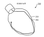
図2A−2Dを参照すると、例示的な治療に従って心室の形状検出が例示的に示される。図2Aは、拡張期(ED)の位置にある左心室(LV)200の図を示す。形状検出カテーテル202が挿入され、心筋の内面210に隣接して位置決められる。図2Bは、収縮期(ES)の位置にある左心室(LV)200、及び内側の境界210に隣接するカテーテル202'を示す。図2Cは、カテーテル202(202')の理論化した位置を示し、一方が他方に重畳して心周期中の心筋の運動を示す。内側にあるカテーテルの位置は、画像が図2Bからであることを示すために202'と示される。図2Dは、LV200の拡張期と収縮期との間の変位を定量化する矢印212を示す。この技術は、LV200の別々の領域が受けている運動及びこれら運動の間の如何なる関係も判断するのに用いられる。
Referring to FIGS. 2A-2D, ventricular shape detection is illustratively shown in accordance with an exemplary treatment. FIG. 2A shows a view of the left ventricle (LV) 200 in the diastolic (ED) position. A
形状検出に基づく前記フレキシブル器具(例えばカテーテル102、202、202')の運動のリアルタイムのトラッキングが使用され、このフレキシブル器具102と接している心筋セグメントの運動特性を得る。3次元(3D)の運動モデルは、異なる切断面において心臓の運動挙動にインターロゲーションを行うように、前記器具202が操縦される幾つかの逐次的な心周期から構築されることができる。
Real-time tracking of the movement of the flexible instrument (eg,
前記システムの範囲は、心筋における増大又は減少する運動の領域を検出することによりさらに広げられる。これは、システムに術中に虚血領域(瘢痕組織)を検出又は検証することを可能にして、必要ならばペースメーカーのリード線の挿入、心筋生検、アルコールアブレーション若しくは他の標的療法の部位を更新又は修正することを可能にする。 The scope of the system is further expanded by detecting areas of increasing or decreasing motion in the myocardium. This allows the system to detect or verify ischemic areas (scar tissue) during surgery and update the site of pacemaker lead insertion, myocardial biopsy, alcohol ablation or other targeted therapy if necessary Or it can be modified.
形状検出を可能にするカテーテル202は、U字若しくはV字形状に事前に成形されることができる、又はバルーン若しくは他のバイアス装置を用いて器官の表面に接触することができる。形状検出を可能にするカテーテル202は、心臓が機能している間、心臓又は他の器官の壁に隣接して置かれる。カテーテル202の内部機構(例えば誘導又は剛性制御)は、心筋組織と密な接触の制御を可能にする。対向する心臓壁の運動パターンの間の関係性又は相関性(若しくはそれらが無いこと)を決めることは、前記システム100が例えばCRTにおいてリード線を配置する可能性のある部位を選択、認証又は処分するのに用いられるリアルタイムの同期不全情報を与えることを可能にする。
The
図2A−2Dに示される例において、収縮期及び拡張期の容積の推定が表されている。しかしながら、他のパラメタ、例えば駆出率、心臓容積及び心拍出量等が同じ方法で決められてもよく、これらは全て心臓のリアルタイムの機能情報を与える。左心室(LV)の内壁に隣接して置かれるとき、前記形状検出するファイバは、定められた切断面若しくは視点からの前記室の境界及び形状を与える。標準的な切断面又は斜視図による測定を用いる場合、前記システムは、長軸及び短軸に沿う長さを得ること、及び関心のある心臓機能又はパラメタを推定することができる。形状検出技術及び(FBG技術が用いられたとしても)特にレイリー若しくはブリルアン後方散乱を用いる場合、カテーテル202の連続するセグメントにわたるデータが達成される。これは、データの無い地点(dead spot)及び離散するデータ収集点は存在しないことを意味している。連続時間スケールにわたり、カテーテル202の全長にわたるデータが集められる。これは、もっと完全なデータセットを提供し、このデータセットは、良好な医学的評価、良好な医学的意思決定及び即時のフィードバックをもたらす。
In the example shown in FIGS. 2A-2D, an estimate of systolic and diastolic volume is presented. However, other parameters such as ejection fraction, heart volume and cardiac output may be determined in the same way, all of which give real-time functional information of the heart. When placed adjacent to the inner wall of the left ventricle (LV), the shape sensing fiber provides the chamber boundary and shape from a defined cut plane or viewpoint. When using standard cut or perspective measurements, the system can obtain lengths along the major and minor axes and estimate the cardiac function or parameter of interest. Data over successive segments of the
機能する心臓から集められるデータは、モデル又は他の機構、例えば公式、ソフトウェア解析ツール等を使用して、例えばモジュール115(図1)を用いることにより解釈されてもよい。例として、以下のことは、容積を得るために上記測定値がどの様に用いられるかを説明するために、以下のことが考えられる。各々の円形スライスに対する領域が計算される既知のシンプソンの法則を用いて容積が計算され、これはこの容積を求めるために主軸の全長(L、ここでh=L/3)が積分される。代わりに、円形の範囲が3つの異なるレベル、すなわち僧帽弁(A1)、乳頭筋(A2)、心尖(A3)において計算される既知の修正されるシンプソンの法則が用いられてもよく、容積(V)は、以下の等式のように計算される。

他のモデル、公式及び解析プログラムが用いられてもよい。 Other models, formulas and analysis programs may be used.
本原理に従って、治療の効果は、臨床医により直ちに評価されることができる。例えば、数分の内に影響を及ぼすアルコールアブレーションの場合、臨床医は、この治療が期待した影響及び程度を及ぼしたかを判断することができ、そうでない場合、後日に繰り返しのインターベンションが続く術後のスキャンを待つのではなく、同じ治療中に修正することを可能にする。同様に、同期不全の場合、インターベンショナリストは、ペースメーカーのリードの位置が所望する効果を持たなかったと結論付け、故に前記リード線を心筋の他の何らかの部位に再位置決めを行う。結果として、インターベンショナリストは、この治療が失敗であったかが分かり、カテーテル室を離れることなく修正を行うことができる。 In accordance with this principle, the effectiveness of the treatment can be immediately evaluated by the clinician. For example, in the case of alcohol ablation that affects within a few minutes, the clinician can determine if this treatment has had the expected impact and extent, otherwise it will be followed by repeated interventions at a later date. Rather than waiting for a later scan, it can be corrected during the same treatment. Similarly, in the event of dyssynchrony, the interventionist concludes that the position of the pacemaker lead did not have the desired effect and therefore repositions the lead to some other location in the myocardium. As a result, the interventionist knows if this treatment was unsuccessful and can make corrections without leaving the catheter room.
他の実施例において、本原理に従って他の器官が評価又は研究されてもよい。例えば、形状検出可能なフレキシブル器具102、202が抹消血管系の特定の位置内に置かれることができる。従って、局所解剖に強いると、前記フレキシブル器具102、202も血管の変形に追従する。心臓血管パラメタ、例えば機械機能、動脈脈波伝播速度又は血管拡張等は、術中ガイダンス及び意思決定のために同様に得られる及び使用される。
In other embodiments, other organs may be evaluated or studied according to the present principles. For example, a shape-detectable
図3を参照すると、ブロック/流れ図は、機能する器官、特に本原理に従って心臓を評価するためのシステム/方法を示す。ブロック300において、検出可能なフレキシブル装置の長さにわたり誘起歪みを連続して検出するために構成される少なくとも1つの光ファイバを持つ前記検出可能なフレキシブル装置は、機能する器官の室に挿入される。この検出可能なフレキシブル装置は、カテーテル、カイドワイヤ、圧力ワイヤ又は電極リード線を含み、好ましくは3次元の連続する時空間情報を供給する。前記室は、心室、血管構造、肺の一部等を含む。前記器官が心臓を含む場合、内壁は心内膜境界又は心外膜境界を含んでいる。
Referring to FIG. 3, a block / flow diagram illustrates a system / method for evaluating a functioning organ, particularly the heart according to the present principles. At
ブロック302において、前記検出可能なフレキシブル装置は、器官の対向する壁における変位を測定するために、好ましくは切断面に沿って前記室においてU字若しくはV字形構造又はバルーン形構造に成形される。
In
ブロック304において、前記フレキシブル装置は、前記長さにわたり器官の内壁と連動するように操縦される。この操縦は、カテーテル等を用いて使用するための従来知られる誘導又は剛性制御を用いてもよい。ブロック306において、前記少なくとも1つの光ファイバからの光信号は、器官が機能している間、この器官の少なくとも2つの運動段階に対し受信される。これら少なくとも2つの運動段階は、心臓の拡張期の位置及び収縮期の位置を含んでもよい。ブロック308において、前記光信号は、前記フレキシブル装置の有効長にわたる連続するデータを供給するために、この長さにわたる連続する後方散乱光を含む。
In
ブロック310において、光信号は、前記器官の機能に関連するパラメタを定量化するために解釈される。ブロック312において、光信号の解釈は、心臓容積の推定、機械機能の決定、運動特性の決定、駆出率の決定、心拍出量の決定等の1つ以上に用いられてもよい。
At block 310, the optical signal is interpreted to quantify parameters associated with the function of the organ. In
ブロック314において、前記フレキシブル装置からの光フィードバックに基づいて手術の支援が与えられる。これは、データをモデル、事前に集めたデータ、統計、公式又はソフトウェア解析パッケージに基づく計算パラメタと比較する等のステップを含む。ブロック316において、ペースメーカーを挿入するための標的部位は、形状検出する機械機能データに基づいて示唆されてもよい。ブロック318において、病理組織の変形パターンを用いて、前記機械機能データが瘢痕位置にマッピングされる。ブロック320において、他の評価、判定等若しくは他の治療が実行されてもよい。
At
付随する特許請求の範囲を解釈する際、当然のことながら、
a)"有する"という言葉は、所与の請求項に挙げられている要素又は行為以外の要素又は行為の存在を排除するものではない。
b)要素が複数あることを述べないことが、これら要素が複数あることを排除するものではない。
c)請求項における如何なる参照符号も、これら請求項の範囲を制限するものではない。
d)幾つかの"手段"は、同じアイテム若しくはハードウェア、又はソフトウェアを実装した構造若しくは機能により示されてもよい。
e)特に示されない限り、特定のシーケンスの行為が必要とされることを意図しない。
である。
When interpreting the appended claims, it should be understood that
a) the word “comprising” does not exclude the presence of other elements or acts than those listed in a given claim;
b) Not to mention that there are a plurality of elements does not exclude a plurality of these elements.
c) any reference signs in the claims do not limit their scope;
d) Several “means” may be indicated by the same item or hardware, or software implemented structure or function.
e) It is not intended that a specific sequence of actions be required unless otherwise indicated.
It is.
リアルタイムの内蔵の機械機能を評価するための形状検出する装置の(これらは例示的であり、限定的ではない)好ましい実施例を開示する場合、上記教えを踏まえて、当業者が修正及び変形を行うことができることに注意されたい。従って、付随の請求項により述べられるように、ここに開示される実施例の範囲内にある、開示される特定の実施例において変更が行われてもよいと理解されるべきである。詳細を開示する及び特に特許法により要求される場合、特許証により保護される特許請求の範囲は添付した請求項に述べられている。 When disclosing preferred embodiments of shape detection devices for evaluating built-in machine functions in real time (these are exemplary and not limiting), one of ordinary skill in the art would make modifications and variations in light of the above teachings. Note that it can be done. Accordingly, it is to be understood that changes may be made in the particular embodiments disclosed which are within the scope of the embodiments disclosed herein as set forth by the appended claims. The claims, which are protected by patent certificate, are set forth in the appended claims, as they disclose details and, in particular, as required by patent law.
Claims (28)
前記器官が機能している間、前記器官の少なくとも2つの運動段階の間に前記少なくとも1つの光ファイバから光信号を受信し、及び前記器官の機能に関連するパラメタを定量化するために前記光信号を解釈するように構成される解釈モジュール
を有するシステム。 The detectable flexible device having at least one optical fiber configured to continuously detect the induced strain over the length of the detectable flexible device and capable of interlocking with an organ wall over the length The flexible device including an operating mechanism configured to: receive an optical signal from the at least one optical fiber during at least two motion stages of the organ while the organ is functioning; and A system comprising an interpretation module configured to interpret the optical signal to quantify parameters associated with the function of the organ.
処理器、
前記処理器に結合されるメモリ
検出可能なフレキシブル装置の長さにわたり誘起歪みを連続して検出するように構成される少なくとも1つの光ファイバを持つ前記検出可能なフレキシブル装置、
前記フレキシブル装置に一体化され、前記フレキシブル装置と前記長さにわたる心臓の壁及び/又は血管との連動状態を可能にするように構成される操作機構、
前記メモリに記憶され、及び前記心臓が機能している間、前記心臓の少なくとも2つの運動段階の間に前記少なくとも1つの光ファイバからフィードバック信号を受信するように構成される解釈モジュールであり、前記誘起歪みに基づいて、前記心臓の機能に関連するパラメタを定量化するためのデータを生成する前記解釈モジュール、並びに
前記機能する心臓の治療を支援するための画像を生成するように構成されるディスプレイ
を有するワークステーション。 A workstation to evaluate the functional heart,
Processor,
A memory coupled to the processor, the detectable flexible device having at least one optical fiber configured to continuously detect induced strain over the length of the detectable flexible device;
An operating mechanism integrated with the flexible device and configured to allow interlocking of the flexible device with the heart wall and / or blood vessel over the length;
An interpretation module stored in the memory and configured to receive a feedback signal from the at least one optical fiber during at least two motion phases of the heart while the heart is functioning; The interpretation module that generates data for quantifying parameters related to the function of the heart based on the induced strain, and a display configured to generate an image to support treatment of the functioning heart Having a workstation.
前記長さにわたり前記器官の境界と連動するように前記フレキシブル装置を操作するステップ、
前記器官が機能している間、前記器官の少なくとも2つの運動段階に対し前記少なくとも1つの光ファイバからフィードバック信号を受信するステップ、及び
前記器官の機能に関連するパラメタを定量化するために前記フィードバック信号を解釈するステップ
を有する方法。 Inserting said flexible device having at least one optical fiber configured to continuously detect induced strain over the length of the detectable flexible device into a chamber or blood vessel of a functioning organ;
Manipulating the flexible device to interlock with the boundaries of the organ over the length;
Receiving a feedback signal from the at least one optical fiber for at least two movement stages of the organ while the organ is functioning; and the feedback to quantify parameters associated with the function of the organ A method comprising the step of interpreting a signal.
Applications Claiming Priority (3)
| Application Number | Priority Date | Filing Date | Title |
|---|---|---|---|
| US201161549298P | 2011-10-20 | 2011-10-20 | |
| US61/549,298 | 2011-10-20 | ||
| PCT/IB2012/055742 WO2013057708A1 (en) | 2011-10-20 | 2012-10-19 | Shape sensing devices for real-time mechanical function assessment of an internal organ |
Related Child Applications (1)
| Application Number | Title | Priority Date | Filing Date |
|---|---|---|---|
| JP2017141610A Division JP2017217495A (en) | 2011-10-20 | 2017-07-21 | Shape sensing devices for real-time mechanical function assessment of internal organ |
Publications (2)
| Publication Number | Publication Date |
|---|---|
| JP2015506720A true JP2015506720A (en) | 2015-03-05 |
| JP2015506720A5 JP2015506720A5 (en) | 2015-11-26 |
Family
ID=47326238
Family Applications (2)
| Application Number | Title | Priority Date | Filing Date |
|---|---|---|---|
| JP2014536395A Pending JP2015506720A (en) | 2011-10-20 | 2012-10-19 | Shape detection device for evaluating real-time built-in machine functions |
| JP2017141610A Withdrawn JP2017217495A (en) | 2011-10-20 | 2017-07-21 | Shape sensing devices for real-time mechanical function assessment of internal organ |
Family Applications After (1)
| Application Number | Title | Priority Date | Filing Date |
|---|---|---|---|
| JP2017141610A Withdrawn JP2017217495A (en) | 2011-10-20 | 2017-07-21 | Shape sensing devices for real-time mechanical function assessment of internal organ |
Country Status (7)
| Country | Link |
|---|---|
| US (1) | US20140243687A1 (en) |
| EP (1) | EP2744409A1 (en) |
| JP (2) | JP2015506720A (en) |
| CN (1) | CN103957792B (en) |
| BR (1) | BR112014009342A2 (en) |
| IN (1) | IN2014CN02657A (en) |
| WO (1) | WO2013057708A1 (en) |
Families Citing this family (7)
| Publication number | Priority date | Publication date | Assignee | Title |
|---|---|---|---|---|
| WO2014187708A1 (en) * | 2013-05-22 | 2014-11-27 | Koninklijke Philips N.V. | Processing apparatus for processing optical shape sensing data values |
| JP6713987B2 (en) * | 2014-09-08 | 2020-06-24 | コーニンクレッカ フィリップス エヌ ヴェKoninklijke Philips N.V. | Shape detection for orthopedic navigation |
| CN107427213B (en) * | 2014-11-03 | 2021-04-16 | 460医学股份有限公司 | System and method for evaluation of contact quality |
| US20170084036A1 (en) * | 2015-09-21 | 2017-03-23 | Siemens Aktiengesellschaft | Registration of video camera with medical imaging |
| WO2017055620A1 (en) * | 2015-10-02 | 2017-04-06 | Koninklijke Philips N.V. | Hub for device navigation with optical shape sensed guidewire |
| US10542941B2 (en) * | 2017-06-05 | 2020-01-28 | Biosense Webster (Israel) Ltd. | Integrated assessment of electrical activation and myocardial strain |
| CN114199145B (en) * | 2021-12-07 | 2022-10-21 | 桂林电子科技大学 | Diameter and roundness detection device for expanded diameter pipeline based on distributed optical fiber sensing |
Citations (2)
| Publication number | Priority date | Publication date | Assignee | Title |
|---|---|---|---|---|
| US20080255629A1 (en) * | 2004-11-01 | 2008-10-16 | Proteus Biomedical, Inc. | Cardiac Motion Characterization by Strain Measurement |
| JP2010514469A (en) * | 2006-12-20 | 2010-05-06 | カーディアック ペースメイカーズ, インコーポレイテッド | Rate-adaptive cardiac pacing system and method |
Family Cites Families (9)
| Publication number | Priority date | Publication date | Assignee | Title |
|---|---|---|---|---|
| NZ509877A (en) * | 2001-04-09 | 2003-08-29 | Bomac Lab Ltd | Composition and administration of copper dextran for treating copper deficiency in animals |
| JP4511425B2 (en) * | 2005-07-01 | 2010-07-28 | 株式会社エルモ社 | Imaging device |
| EP2363073B1 (en) * | 2005-08-01 | 2015-10-07 | St. Jude Medical Luxembourg Holding S.à.r.l. | Medical apparatus system having optical fiber load sensing capability |
| US7814803B2 (en) * | 2006-03-02 | 2010-10-19 | Nsk Ltd. | Torque sensor |
| JP5775670B2 (en) * | 2007-02-14 | 2015-09-09 | コーニンクレッカ フィリップス エヌ ヴェ | System, method and computer program for determining functional characteristics of moving object |
| CN101796542A (en) * | 2007-07-05 | 2010-08-04 | 西门子工业公司 | Arrangement and method for procesing image data |
| JP2009163643A (en) * | 2008-01-09 | 2009-07-23 | Sony Corp | Video retrieval device, editing device, video retrieval method and program |
| CN104605928B (en) * | 2009-05-08 | 2018-01-05 | 圣犹达医疗用品国际控股有限公司 | System for controlling lesion size in the ablation based on conduit |
| US8265431B2 (en) * | 2009-11-06 | 2012-09-11 | Baker Hughes Incorporated | Rotated single or multicore optical fiber |
-
2012
- 2012-10-19 US US14/351,940 patent/US20140243687A1/en not_active Abandoned
- 2012-10-19 EP EP12798840.0A patent/EP2744409A1/en not_active Withdrawn
- 2012-10-19 CN CN201280051306.9A patent/CN103957792B/en not_active Expired - Fee Related
- 2012-10-19 IN IN2657CHN2014 patent/IN2014CN02657A/en unknown
- 2012-10-19 BR BR112014009342A patent/BR112014009342A2/en not_active IP Right Cessation
- 2012-10-19 WO PCT/IB2012/055742 patent/WO2013057708A1/en active Application Filing
- 2012-10-19 JP JP2014536395A patent/JP2015506720A/en active Pending
-
2017
- 2017-07-21 JP JP2017141610A patent/JP2017217495A/en not_active Withdrawn
Patent Citations (2)
| Publication number | Priority date | Publication date | Assignee | Title |
|---|---|---|---|---|
| US20080255629A1 (en) * | 2004-11-01 | 2008-10-16 | Proteus Biomedical, Inc. | Cardiac Motion Characterization by Strain Measurement |
| JP2010514469A (en) * | 2006-12-20 | 2010-05-06 | カーディアック ペースメイカーズ, インコーポレイテッド | Rate-adaptive cardiac pacing system and method |
Also Published As
| Publication number | Publication date |
|---|---|
| US20140243687A1 (en) | 2014-08-28 |
| BR112014009342A2 (en) | 2017-04-18 |
| CN103957792B (en) | 2017-05-03 |
| CN103957792A (en) | 2014-07-30 |
| EP2744409A1 (en) | 2014-06-25 |
| IN2014CN02657A (en) | 2015-06-26 |
| WO2013057708A1 (en) | 2013-04-25 |
| JP2017217495A (en) | 2017-12-14 |
Similar Documents
| Publication | Publication Date | Title |
|---|---|---|
| JP6129750B2 (en) | Non-rigid morphing of blood vessel images using the shape of the device in the blood vessel | |
| JP2017217495A (en) | Shape sensing devices for real-time mechanical function assessment of internal organ | |
| JP6216770B2 (en) | Artifact removal by shape detection | |
| JP6114748B2 (en) | Curved multiplanar reconstruction using optical fiber shape data | |
| US9820695B2 (en) | Method for detecting contact with the wall of a region of interest | |
| JP6719885B2 (en) | Positioning map using intracardiac signals | |
| EP2608720B1 (en) | Mapping system for medical procedures | |
| JP6906113B2 (en) | Devices, systems and methods for visualizing cyclically moving biological structures | |
| US10342620B2 (en) | Efficient treatment of atrial fibrillation using three-dimensional electrical potential model | |
| JP6280558B2 (en) | Temperature distribution determination device | |
| US20150141764A1 (en) | Distributed sensing device for referencing of physiological features | |
| JP2022502106A (en) | Intravascular device movement speed guidance, as well as related devices, systems, and methods. | |
| JP2023015189A (en) | System and method for real-time creation of cardiac electro-physiology signals in the heart | |
| US11406278B2 (en) | Non-rigid-body morphing of vessel image using intravascular device shape | |
| EP4138672B1 (en) | Automated control of intraluminal data acquisition and associated devices, systems, and methods | |
| US11553867B2 (en) | Systems and methods for displaying EP maps using confidence metrics | |
| WO2023235854A1 (en) | Systems and methods for endoluminal tracking with therapeutic delivery sensing |
Legal Events
| Date | Code | Title | Description |
|---|---|---|---|
| A521 | Request for written amendment filed |
Free format text: JAPANESE INTERMEDIATE CODE: A523 Effective date: 20151002 |
|
| A621 | Written request for application examination |
Free format text: JAPANESE INTERMEDIATE CODE: A621 Effective date: 20151002 |
|
| A131 | Notification of reasons for refusal |
Free format text: JAPANESE INTERMEDIATE CODE: A131 Effective date: 20160901 |
|
| A977 | Report on retrieval |
Free format text: JAPANESE INTERMEDIATE CODE: A971007 Effective date: 20160831 |
|
| A601 | Written request for extension of time |
Free format text: JAPANESE INTERMEDIATE CODE: A601 Effective date: 20161201 |
|
| RD04 | Notification of resignation of power of attorney |
Free format text: JAPANESE INTERMEDIATE CODE: A7424 Effective date: 20170214 |
|
| A521 | Request for written amendment filed |
Free format text: JAPANESE INTERMEDIATE CODE: A523 Effective date: 20170301 |
|
| A02 | Decision of refusal |
Free format text: JAPANESE INTERMEDIATE CODE: A02 Effective date: 20170323 |
|
| A521 | Request for written amendment filed |
Free format text: JAPANESE INTERMEDIATE CODE: A523 Effective date: 20170721 |
|
| A911 | Transfer to examiner for re-examination before appeal (zenchi) |
Free format text: JAPANESE INTERMEDIATE CODE: A911 Effective date: 20170728 |
|
| A912 | Re-examination (zenchi) completed and case transferred to appeal board |
Free format text: JAPANESE INTERMEDIATE CODE: A912 Effective date: 20170908 |