JP2015501625A - System that integrates DC power from multiple inputs - Google Patents
System that integrates DC power from multiple inputs Download PDFInfo
- Publication number
- JP2015501625A JP2015501625A JP2014533367A JP2014533367A JP2015501625A JP 2015501625 A JP2015501625 A JP 2015501625A JP 2014533367 A JP2014533367 A JP 2014533367A JP 2014533367 A JP2014533367 A JP 2014533367A JP 2015501625 A JP2015501625 A JP 2015501625A
- Authority
- JP
- Japan
- Prior art keywords
- current
- bus bar
- noise
- power
- sensor
- Prior art date
- Legal status (The legal status is an assumption and is not a legal conclusion. Google has not performed a legal analysis and makes no representation as to the accuracy of the status listed.)
- Pending
Links
- 230000004044 response Effects 0.000 claims abstract description 18
- 239000004020 conductor Substances 0.000 claims description 25
- 238000000034 method Methods 0.000 claims description 11
- 230000007257 malfunction Effects 0.000 claims description 10
- 230000005355 Hall effect Effects 0.000 claims description 8
- 238000004891 communication Methods 0.000 claims description 6
- 238000001514 detection method Methods 0.000 abstract description 35
- 238000012544 monitoring process Methods 0.000 abstract description 23
- 238000010248 power generation Methods 0.000 abstract description 9
- 230000007547 defect Effects 0.000 description 7
- 238000010891 electric arc Methods 0.000 description 6
- 230000005611 electricity Effects 0.000 description 6
- 238000010586 diagram Methods 0.000 description 5
- 230000007613 environmental effect Effects 0.000 description 5
- 230000008569 process Effects 0.000 description 4
- 238000012545 processing Methods 0.000 description 3
- 238000003491 array Methods 0.000 description 2
- 239000000872 buffer Substances 0.000 description 2
- 230000002950 deficient Effects 0.000 description 2
- 239000010445 mica Substances 0.000 description 2
- 229910052618 mica group Inorganic materials 0.000 description 2
- 238000012986 modification Methods 0.000 description 2
- 230000004048 modification Effects 0.000 description 2
- RYGMFSIKBFXOCR-UHFFFAOYSA-N Copper Chemical compound [Cu] RYGMFSIKBFXOCR-UHFFFAOYSA-N 0.000 description 1
- 229910000831 Steel Inorganic materials 0.000 description 1
- 230000009471 action Effects 0.000 description 1
- XAGFODPZIPBFFR-UHFFFAOYSA-N aluminium Chemical compound [Al] XAGFODPZIPBFFR-UHFFFAOYSA-N 0.000 description 1
- 229910052782 aluminium Inorganic materials 0.000 description 1
- 238000004458 analytical method Methods 0.000 description 1
- 230000000903 blocking effect Effects 0.000 description 1
- 229910052802 copper Inorganic materials 0.000 description 1
- 239000010949 copper Substances 0.000 description 1
- 230000001934 delay Effects 0.000 description 1
- 230000000694 effects Effects 0.000 description 1
- 239000011152 fibreglass Substances 0.000 description 1
- 239000005431 greenhouse gas Substances 0.000 description 1
- 239000000463 material Substances 0.000 description 1
- 230000007246 mechanism Effects 0.000 description 1
- 238000011017 operating method Methods 0.000 description 1
- 229920000728 polyester Polymers 0.000 description 1
- 230000009467 reduction Effects 0.000 description 1
- 239000010959 steel Substances 0.000 description 1
- 230000001052 transient effect Effects 0.000 description 1
Images


Classifications
-
- H—ELECTRICITY
- H02—GENERATION; CONVERSION OR DISTRIBUTION OF ELECTRIC POWER
- H02H—EMERGENCY PROTECTIVE CIRCUIT ARRANGEMENTS
- H02H7/00—Emergency protective circuit arrangements specially adapted for specific types of electric machines or apparatus or for sectionalised protection of cable or line systems, and effecting automatic switching in the event of an undesired change from normal working conditions
- H02H7/22—Emergency protective circuit arrangements specially adapted for specific types of electric machines or apparatus or for sectionalised protection of cable or line systems, and effecting automatic switching in the event of an undesired change from normal working conditions for distribution gear, e.g. bus-bar systems; for switching devices
-
- H—ELECTRICITY
- H02—GENERATION; CONVERSION OR DISTRIBUTION OF ELECTRIC POWER
- H02H—EMERGENCY PROTECTIVE CIRCUIT ARRANGEMENTS
- H02H1/00—Details of emergency protective circuit arrangements
- H02H1/0007—Details of emergency protective circuit arrangements concerning the detecting means
- H02H1/0015—Using arc detectors
-
- H—ELECTRICITY
- H01—ELECTRIC ELEMENTS
- H01L—SEMICONDUCTOR DEVICES NOT COVERED BY CLASS H10
- H01L31/00—Semiconductor devices sensitive to infrared radiation, light, electromagnetic radiation of shorter wavelength or corpuscular radiation and specially adapted either for the conversion of the energy of such radiation into electrical energy or for the control of electrical energy by such radiation; Processes or apparatus specially adapted for the manufacture or treatment thereof or of parts thereof; Details thereof
- H01L31/02—Details
- H01L31/02016—Circuit arrangements of general character for the devices
- H01L31/02019—Circuit arrangements of general character for the devices for devices characterised by at least one potential jump barrier or surface barrier
- H01L31/02021—Circuit arrangements of general character for the devices for devices characterised by at least one potential jump barrier or surface barrier for solar cells
-
- H—ELECTRICITY
- H02—GENERATION; CONVERSION OR DISTRIBUTION OF ELECTRIC POWER
- H02H—EMERGENCY PROTECTIVE CIRCUIT ARRANGEMENTS
- H02H3/00—Emergency protective circuit arrangements for automatic disconnection directly responsive to an undesired change from normal electric working condition with or without subsequent reconnection ; integrated protection
- H02H3/08—Emergency protective circuit arrangements for automatic disconnection directly responsive to an undesired change from normal electric working condition with or without subsequent reconnection ; integrated protection responsive to excess current
-
- H—ELECTRICITY
- H02—GENERATION; CONVERSION OR DISTRIBUTION OF ELECTRIC POWER
- H02H—EMERGENCY PROTECTIVE CIRCUIT ARRANGEMENTS
- H02H7/00—Emergency protective circuit arrangements specially adapted for specific types of electric machines or apparatus or for sectionalised protection of cable or line systems, and effecting automatic switching in the event of an undesired change from normal working conditions
- H02H7/20—Emergency protective circuit arrangements specially adapted for specific types of electric machines or apparatus or for sectionalised protection of cable or line systems, and effecting automatic switching in the event of an undesired change from normal working conditions for electronic equipment
-
- Y—GENERAL TAGGING OF NEW TECHNOLOGICAL DEVELOPMENTS; GENERAL TAGGING OF CROSS-SECTIONAL TECHNOLOGIES SPANNING OVER SEVERAL SECTIONS OF THE IPC; TECHNICAL SUBJECTS COVERED BY FORMER USPC CROSS-REFERENCE ART COLLECTIONS [XRACs] AND DIGESTS
- Y02—TECHNOLOGIES OR APPLICATIONS FOR MITIGATION OR ADAPTATION AGAINST CLIMATE CHANGE
- Y02E—REDUCTION OF GREENHOUSE GAS [GHG] EMISSIONS, RELATED TO ENERGY GENERATION, TRANSMISSION OR DISTRIBUTION
- Y02E10/00—Energy generation through renewable energy sources
- Y02E10/50—Photovoltaic [PV] energy
Abstract
複数の直流電流電源を統合するシステムを提供する。前記システムは、ソーラーパネルアレイなどの、発電素子のアレイからの複数の供給を統合し単一の電圧出力とするように動作可能である。前記システムは各入力からの電流を監視し、特定の出力に関連した不具合またはその他の問題の有無を判定するように動作可能な電流監視アセンブリを含む。前記システムは電流を監視して不具合またはその他の問題の有無を判定するノイズ検出アセンブリを含む。前記電流監視アセンブリおよび前記ノイズ検出アセンブリからの出力に応答して、前記アレイ中の発電素子を分析する必要があるという旨の警報またはその他の信号を、操作者に対して提供することが出来る。【選択図】 図1A system for integrating a plurality of direct current power supplies is provided. The system is operable to consolidate multiple supplies from an array of power generation elements, such as a solar panel array, into a single voltage output. The system includes a current monitoring assembly that is operable to monitor the current from each input and determine whether there is a fault or other problem associated with a particular output. The system includes a noise detection assembly that monitors current to determine if there is a fault or other problem. In response to outputs from the current monitoring assembly and the noise detection assembly, an alarm or other signal can be provided to the operator that the power generation elements in the array need to be analyzed. [Selection] Figure 1
Description
本出願は、2011年9月30日に出願された米国仮出願第61/541,206号に対する優先権を主張する。前記特許出願の開示全体が参照により本明細書中に組み込まれる。 This application claims priority to US Provisional Application No. 61 / 541,206, filed September 30, 2011. The entire disclosure of said patent application is incorporated herein by reference.
本発明は複数の電源を統合し単一の出力を提供する技術に関する。より詳細には、本発明は複数のソーラーパネルまたは複数のソーラーパネルアレイにより生成された電力を統合するシステムに関する。 The present invention relates to a technique for integrating a plurality of power supplies to provide a single output. More particularly, the present invention relates to a system for integrating power generated by multiple solar panels or multiple solar panel arrays.
発電を目的としたソーラーパネルの利用は、個人および事業が電力コスト削減および温室効果ガス排出削減のための方法を模索するにしたがって拡大を続けている。太陽光電力の利用が増大するにつれて、太陽光電力を生産するために使用されるアレイのサイズも増大している。このエネルギーを繋ぎ合わせるためには、アレイの各部分からの電気出力を統合することが望ましいが、そのためにはそうした様々な部分の出力の監視し、ソーラーアレイのある部分における不具合の有無を検出できるようにすることが望ましい。重大な損傷へと繋がりうる不具合の一つは、アーク放電である。大規模なソーラーアレイは高い電圧を生成し、このアレイからの回路の一つに短絡があれば、ソーラーパネルが太陽光の中にある限り配線がアーク放電する。このアーク放電は、極度な高温を発生させ、絶縁部品、連結部品、または容器を、燃焼させるかまたは溶融させる可能性がある。 The use of solar panels for power generation continues to expand as individuals and businesses seek ways to reduce power costs and reduce greenhouse gas emissions. As the use of solar power increases, the size of the array used to produce solar power also increases. In order to connect this energy, it is desirable to integrate the electrical output from each part of the array, but this can be done by monitoring the output of these various parts and detecting the presence or absence of defects in some parts of the solar array. It is desirable to do so. One malfunction that can lead to serious damage is arcing. Large solar arrays generate high voltages, and if one of the circuits from this array has a short circuit, the wiring will arc as long as the solar panel is in sunlight. This arcing can generate extremely high temperatures and can cause the insulating, connecting, or container to burn or melt.
本発明は、ソーラーパネルの複数の電源回路を統合して、単一の統合された出力回路を生成するためのシステムを提供する。一態様において、前記システムは複数の光起電力電源からの電流を感知する感知器と、当該複数の光起電力電源からの電流中のノイズを検出するノイズ検出器とを備える。前記感知器および前記ノイズ検出器に接続する制御器は、前記感知器および前記ノイズ検出器からの信号に基づいて、不具合の有無を判定するように構成されている。もし前記制御器が不具合が発生したものと判定した場合、前記制御器は前記光起電力素子を前記出力回路から切断する切替器を制御してもよい。 The present invention provides a system for integrating multiple power supply circuits of a solar panel to produce a single integrated output circuit. In one aspect, the system includes a sensor that senses current from a plurality of photovoltaic power sources and a noise detector that detects noise in the current from the plurality of photovoltaic power sources. A controller connected to the sensor and the noise detector is configured to determine the presence or absence of a defect based on signals from the sensor and the noise detector. If the controller determines that a failure has occurred, the controller may control a switch that disconnects the photovoltaic element from the output circuit.
前記システムはさらに、各電源回路からの各電気入力の電流を監視する機構を提供する。より詳細には、前記システムは出力回路を作成する複数の光起電力電源回路に取り付けられた統合器アセンブリを含む。1つまたは複数の電源回路からの出力は、バスバー(母線)に接続されている。前記バスバーは複数の伸長したフィンガー(指部)を含み、このフィンガーの各々は前記電源回路の少なくとも1つからの出力と電気的に連絡している。前記バスバーのフィンガーの各々に隣接する感知器は、前記バスバーのフィンガーを通過する電流を検知する。前記感知器は、対応する前記バスバーのフィンガーを通って流れる電流量を示す信号を提供する。前記システムはさらに、一つまたは複数の前記電源回路中の不具合を示すノイズを同定する、前記バスバーの電流中のノイズを検出する検出器アセンブリを含む。 The system further provides a mechanism for monitoring the current of each electrical input from each power supply circuit. More particularly, the system includes an integrator assembly attached to a plurality of photovoltaic power supply circuits that create an output circuit. Outputs from one or more power supply circuits are connected to a bus bar (bus line). The bus bar includes a plurality of elongated fingers, each of which is in electrical communication with an output from at least one of the power supply circuits. A sensor adjacent to each of the bus bar fingers senses the current passing through the bus bar fingers. The sensor provides a signal indicative of the amount of current flowing through the corresponding finger of the bus bar. The system further includes a detector assembly that detects noise in the current of the bus bar that identifies noise indicative of a fault in one or more of the power supply circuits.
別の態様によると、前記電流感知器はホール効果感知器であってもよく、このホール効果感知器によって、生成された信号を用いて各電源回路によって生成される電流量を測定することが可能であるほか、アーク障害などの電源回路中の問題を検出することが可能である。 According to another aspect, the current sensor may be a Hall effect sensor, which can measure the amount of current generated by each power supply circuit using the generated signal. In addition, it is possible to detect problems in the power supply circuit such as arc faults.
別の態様によると、前記ノイズ検出器アセンブリは、前記バスバーから出力接点へと流れる電流を検出する変流器を含んでもよい。前記変流器は、前記バスバーから流れる電流中のノイズに応答して電流を生成してもよい。前記アセンブリはまた、不具合が検出された場合、前記統合器アセンブリの出力を切断し、それによって前記アーク放電が発生している回路中の電流の流れを遮断する接触器を含んでもよい。 According to another aspect, the noise detector assembly may include a current transformer that detects a current flowing from the bus bar to an output contact. The current transformer may generate a current in response to noise in the current flowing from the bus bar. The assembly may also include a contactor that disconnects the output of the integrator assembly when a fault is detected, thereby interrupting current flow in the circuit where the arcing is occurring.
前述の本発明の概要および好ましい実施形態の以下の詳細な説明は、添付の図面と共に読むことにより最も理解されるであろう。
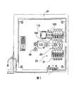
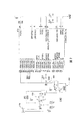
図を参照すると、直流電力を統合するシステムは参照番号10として概略示されている。前記システム10は、図3中にPV1、PV2、PV3、PV4として示されているソーラーパネルのような、複数の電力生成装置からの電力出力を受容する統合器ボックス20を含む。前記統合器ボックス20は、耐候性のスチールまたはファイバーグラスのボックス22のような容器を含む。前記ボックス22の中に、負極ターミナルアセンブリ24および正極ターミナルアセンブリ30が搭載されている。前記電力生成装置PV1〜PV4は、前記正極ターミナルアセンブリ30および負極ターミナルアセンブリ24に接続し、統合して単一の直流出力を生成する。
Referring to the figure, a system for integrating DC power is shown schematically as
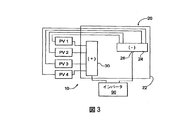
図3を参照すると、前記システム10の詳細がより細部まで記載されている。前記電力生成素子は、電力を生成する様々な装置のいずれであってもよい。本実施形態においては、前記電力生成素子は光起電力(PV:photovoltaic)セルである。より詳細には、前記電力生成素子は複数のソーラーパネルである。統合器ボックス20への各電気入力が、単一のソーラーパネルからのものであってもよい。しかしながら、本実施形態においては、複数のソーラーパネルからの出力は相互接続され単一の電気出力を供給する。これらの相互接続された複数のソーラーパネルはストリングと称される。複数の前記ストリングがソーラーパネルのアレイを形成する。図3において、前記システムはPV1、PV2、PV3、PV4として識別された4つのストリングを含んでいる。しかしながら、PV1〜PV4が単一のソーラーパネルまたは複数のソーラーパネルを表していてもよいことは理解されるべきである。さらに、本システムは太陽光電力の適用先に特に適したものであるが、非太陽光の電力生成素子に対してもまた使用可能である。非太陽光の適用先においては、PV1〜PV4は他の電力生成素子を表す。
Referring to FIG. 3, the details of the
図3において、各ストリング(PV1〜PV4)からの出力は、前記負極ターミナル24および前記正極ターミナル30に接続されている。前記負極ターミナルアセンブリ24は、前記ストリングからの全ての負極導電体を共有する導電体を提供するターミナルブロックを有する。前記負極ターミナルアセンブリ24は、複数のソケットと、前記ストリングの一つからの導電体を受容し維持するための対応するコネクターとを含む。さらに、前記負極ターミナルアセンブリ24は、当該ターミナルアセンブリからの出力負極導電体を接続するための、出力ラグ26を含む。
In FIG. 3, the output from each string (PV1 to PV4) is connected to the
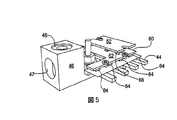
前記正極ターミナルアセンブリ30は、図1および図5〜6においてより詳細に記載されている。前記正極ターミナルアセンブリ30は、回路ブレーカーまたはヒューズなどの、複数の過電流保護素子が取り付けられたバスバー30を含む。本実施形態においては、前記過電流保護素子はヒューズであり、それぞれがヒューズホルダー31に収納されている。図5〜6は典型的な実施形態を図示しており、図中において前記正極ターミナルアセンブリは8つまでの電源入力(例えば、8個のソーラーパネルストリングPV1〜PV8)からの導電体を受容するように構成されている。前記アセンブリは、前記正極導電体の全てが当該アセンブリの片側に接続するように構成されていてもよい。しかしながら本実施形態においては、前記アセンブリーは一対の平行列のヒューズホルダー31を両側に備えている。以下でさらに説明するように、各ヒューズホルダー31の正面部は反対側の列のヒューズホルダーの前面部と対向しており、その結果これらのヒューズホルダーの前面部は列の間に通路を形成し、バスバー40はこれらのヒューズホルダーの列と接続している。
The
各ヒューズホルダー31は、前記電力入力(例えば、PV1〜PV8)の1つから正極導電体を受容する配線ソケットを含む。各ヒューズホルダーにあるコネクタは、前記配線ソケット内に配線を保持するように動作可能である。例えば、前記コネクタは、前記配線を締め付けて固定し前記ソケット内に当該配線を保持するねじ込み素子である。同様に、前記ヒューズホルダー31はまた、当該ヒューズホルダーを前記バスバーソケットに接続する第2のソケットを含む。各ヒューズホルダー31の第2のコネクタは、前記第2のソケット内に前記バスバーを保持するように動作可能である。本実施形態では、前記第2のコネクタは前記配線コネクタ34と類似しており、当該コネクタをねじ込むことにより前記バスバーを前記第2のソケット内に締め付けて固定する。前記正極ターミナルアセンブリの例示的なヒューズホルダー31は、Wohnerによって、商品名AMBUS EasySwitch、パート番号31110として製造されたヒューズホルダーである。
Each
前記正極ターミナルアセンブリ30の例示的なバスバー40が、図4に図示されている。前記バスバー40は、銅、アルミニウム、または他の高導電性材料などの導電素子である。前記バスバー40は、中央導電性本体42と、当該中央導電性本体から突出する複数の伸長したフィンガー44とを含む。本実施形態において、前記フィンガーは前記中央本体の周囲に配置され2列のフィンガーを形成しているが、前記バスバーは、前記フィンガーが前記中央本体の片側からのみ延出するように、または端部の一方もしくは両方から延出するように構成されてもよい。
An
本実施形態において、各列のフィンガーは、前記中央本体42の端部に沿って互いに離間する複数の略平行なフィンガーを有する。前記フィンガー44は、各フィンガーが2つの部分を有するように伸長している。第1の部分は、前記ヒューズホルダーの1つのバスコネクタ33の中に延出するターミナル端部である。第2の部分は、前記ヒューズホルダーの前面37と前記バスバーの端部との間に延出する中間部分である。本実施形態において、前記フィンガーの中間部分は、少なくとも前記フィンガーの約1/4の長さであり、好ましくは少なくとも前記フィンガーの約1/3の長さである。このようにして、前記伸長したフィンガーは、前記ヒューズホルダーの中に延出して当該ヒューズホルダーと電気的接続を形成しながら、一方で前記バスバーの中央本体を前記ヒューズホルダーから離すよう間隔を維持する。
In this embodiment, each row of fingers has a plurality of generally parallel fingers spaced apart from each other along the end of the
上述したように、前記バスバーの各フィンガー44はヒューズホルダーと接続するように構成され、前記ソーラーパネルのストリングの1つの正極導電体と電気的に連絡している。このようにして、前記バスバーの中央本体は、前記正極ターミナルアセンブリに接続されている前記ストリングの全てと電気的に連絡し、これにより前記アセンブリに接続されている前記ストリングによって生成される電力の全てが統合される。
As described above, each
前記バスバーと電気的に接続されている出力ラグ46は、当該バスバーからの単一出力接続を提供する。前記出力ラグ46は、導電体を受け入れるソケット47と、前記出力ラグのソケットの中に出力導電体を保持するための、例えば止めねじまたは他のねじ込み素子などのコネクタ48とを含む。このようにして、前記出力導電体は、前記ソーラーパネルのストリングから前記正極ターミナルアセンブリに接続される電力を統合した電流出力を提供することができる。前記正極出力導電体および前記負極出力導電体は、前記回路の下流の素子と接続することができる。例えば図3に示すように、前記統合器20からの出力は、インバータ90に接続することができる。前記インバータ90は、前記電力を直流から交流に変換する。前記統合器ボックス20からの出力がインバータに接続されてもよいが、前記システムは前記出力がインバータに供給される回路に限定されない。例えば、前記出力は、別のPV統合器または電力貯蔵装置(例えば、電池または電池アレイ)に接続されてもよい。
An
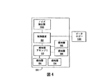
本実施形態において、前記システムはまた、前記正極ターミナルアセンブリに流れる電流を監視する電流監視アセンブリ60と、前記電源回路の1つにおけるアーク放電を示すノイズを検出するノイズ検出アセンブリ160とを含む。前記電流監視アセンブリ60は、前記回路に接続される1つまたは複数のストリングによって供給される電流の減少があるかを検出するように動作可能である。前記ノイズ検出アセンブリ160は、アーク放電を示すノイズを検出するように動作可能である。
In this embodiment, the system also includes a
本実施形態においては、前記制御アセンブリ50は、前記ノイズ検出アセンブリ160からの信号と前記電流監視アセンブリ60からの信号とを受信するマイクロプロセッサーを有する。前記制御アセンブリは、前記ノイズ検出アセンブリ160および前記電流監視アセンブリ60からの信号が、前記電源回路の1つにおける不具合を示すものかを判断する。不具合が存在すると前記制御アセンブリが判断した場合、以下でさらに説明するように、前記制御アセンブリは前記統合器ボックスからの出力を自動的に切断してもよい。
In this embodiment, the
さらに前記制御アセンブリ50はデータ通信素子と出力コネクタとを含み、前記制御センブリからの信号はデータロギング素子100にエクスポートされる。例えば、前記制御センブリは、前記感知器データおよび/またはノイズ検出データを遠隔装置(例えば、ModBusが可能なデータロガー、インバータ、または電力計)と通信する、ModBusなどの共通プロトコルを使用して信号を提供する通信素子を含んでもよい。前記遠隔装置は前記制御基盤からのデータを記録および/または分析して、前記データが1つまたは複数の前記電力入力素子(例えば、PV1〜PV4)のエラーまたは不具合を示すかを決定することができると同時に、不具合があるかを決定するために分析されるべき入力素子を特定することもできる。次に、前記遠隔装置は前記検出された不具合、および不具合または他の性能問題があると思われる電力入力素子を示す信号または警告を操作者に提供する。
The
前記電流監視アセンブリ60は複数の感知器64を含み、各感知器はソーラーパネルのストリングの1つから流れる電気的特徴を検出してもよい。前記感知器は任意の様々な電流検出感知器でよいが、本実施形態では、前記電流検出感知器はホール効果感知器64である。
The
前記ホール効果感知器64は、前記バスバー40に隣接して配置されている回路基板62に搭載される。
The
前記感知器64は、前記回路基板に沿って離間されており、各感知器は前記バスバーのフィンガー44の1つに隣接して配置されている。特に本実施形態において、前記感知器64は離間されて、前記バスバーの隣接するフィンガー44間の距離と実質的に同様の距離で互いに離間された2列の感知器を形成する。このようにして、各感知器は当該感知器の1つに近接して各々の当該フィンガーの電流の変動を検出する。さらに、各感知器は、前記残りのバスバーフィンガーのいずれよりもまたは前記バスバーの中央本体42より各々のバスバーフィンガー44に近い位置に配置され、監視する。
The
前記感知器を、制御素子または前記感知器64からの信号を処理する信号処理素子を含む回路基板に搭載することができる。しかしながら、本実施形態では、前記制御アセンブリ50は前記感知器基板62上の感知器64に電気的に接続されており、前記制御アセンブリは前記感知器64からの信号を受信し処理する。
The sensor can be mounted on a circuit board including a control element or a signal processing element for processing a signal from the
前記制御アセンブリ50は、前記感知器64からの信号を処理して、前記信号が前記各々のバスバーフィンガーに接続されている前記ストリングの素子に問題があることを示す入力電流(または電圧)の変動を示すかどうかを検出してもよい。言い換えれば、PV1が第1のバスバーフィンガーに接続されて、前記第1のフィンガーに接続された前記感知器64が所定の閾値未満の電流を検出した場合、次に前記制御基盤は前記第1の感知器からの信号を処理して、ソーラーパネルの前記第1のストリングに不具合が生じている可能性がある旨の警告を操作者に提供してもよい。しかしながら、以下でさらに説明するように、不具合が存在するという判断は、ライン中のノイズの検出にも基いたものである。
The
図1を参照すると、前記感知器アセンブリ60および前記制御アセンブリ50は、前記2列のヒューズホルダー31の間に形成された通路内で前記バスバーの中央本体42の上に配置されている。薄い電気絶縁層66が前記バスバー40と前記感知器アセンブリ60との間に配置されてもよい。前記絶縁層は、前記感知器64を前記バスバーの中央本体42の電流からまたは前記バスバーの隣接するフィンガー44を通して流れる電流から絶縁する。前記絶縁層66は様々な材料から形成され、本実施形態では薄いシートのマイカ(雲母)である。薄いシートのポリエステルを使用することもできる。
Referring to FIG. 1, the
前記正極ターミナルアセンブリ30はまた、前記高電圧DCバスバーからの電力を利用して、前記電流監視システム50を動作させるように設計される電源装置を組み込んでもよい。特に、前記バスバーは、接地面に対して300〜600ボルトDCの電圧の標準状態のもとで機能してもよい。前記電源装置は、前記バスバー電圧より5、12、または24ボルト低い動作電圧を前記電流監視システムに提供する。したがって、前記電源装置により、前記回路基板は前記バスバー電圧から約24ボルト以下の電圧差で動作することが可能である。
The positive
幾つかの用途または構成において、前記バスバー40の隣接要素によって生成される磁場などの、前記ホール効果センサー64が生成する信号に影響を与えうるノイズおよび/またはバックグラウンド効果を考慮することが望ましい。特に、上述したように、前記バスバー40は複数の独立要素(例えば、フィンガー44)を含み、各独立要素は別々の入力回路に接続されてもよい。別個のホール効果感知器が各伸長したフィンガーに搭載され、前記各々の入力回路から前記バスバー40に流れる電流を監視してもよい。前記フィンガーの1つを通って流れる電流によって生成される磁場は、前記感知器アセンブリの2つ以上の感知器によって感知される磁場を生成する場合もある。例えば、前記バスの第1のフィンガーを通って流れる電流を検出する感知器はまた、前記第2および3のフィンガーを通って流れる電流によって生成される磁場を検出することもできる。実際、幾つかの構成において、各感知器は、前記他のフィンガーの各々を通って流れる電流によって生成される任意の磁場を検出することもできる。
In some applications or configurations, it may be desirable to consider noise and / or background effects that may affect the signal generated by the
各フィンガーを流れる電流を評価するため、各感知器からの信号を補償して、隣接するフィンガーから受信する信号または特定のフィンガーを通って流れる電流を示さない他の信号を把握することが望ましい。隣接するフィンガーよって生成される磁場の主な原因となる信号を処理する1つの方法は、次のように各感知器のベースライン感知器値を決定することである。N数のフィンガーのバスに対して、既知の電流が前記第1のフィンガーに流され、残りのフィンガーの各々には電流を流さない。フィンガー2〜Nの感知器が評価され、フィンガー1を流れる電流に応答して感知された磁場の性質について決定される。次に、前記既知の電流がフィンガー2に流され、フィンガー1および3〜Nには電流を流さない。フィンガー1および3〜Nの感知器が評価され、フィンガー2を通って流れる電流に応答して感知された磁場の性質について決定される。同様に、各フィンガーに別々に電流が流され、前記感知器が各フィンガーに対して評価されて、各特定のフィンガーに流れる信号に応答して各フィンガーで感知された磁場の性質について決定される。
In order to evaluate the current flowing through each finger, it is desirable to compensate the signal from each sensor to understand signals received from adjacent fingers or other signals that do not indicate current flowing through a particular finger. One way to process the signal that is mainly responsible for the magnetic field generated by adjacent fingers is to determine the baseline sensor value for each sensor as follows. For a bus of N fingers, a known current is passed through the first finger and no current is passed through each of the remaining fingers. The sensors of fingers 2 -N are evaluated and determined for the nature of the sensed magnetic field in response to the current flowing through
前記既知の電流を前記フィンガーの各々に流して、結果として起こる磁場が前記感知器によって感知された後、前記感知器が感知するバックグラウンドノイズを決定することができ、前記感知器の前記信号を処理するときに相殺することができる。特に、(監視されているフィンガーを通って流れる電流以外の)フィンガーを通って流れる電流によって生成されるバックグラウンドノイズに対する補償信号は、残りのフィンガーに電流が流されなかった間で前記フィンガーに電流が流されたときに検出された信号と比例する。感知器のベースライン値は、前記バスの(監視されている前記フィンガー以外の)各フィンガーに対する補償の合計に基づいている。 The known current can be passed through each of the fingers to determine the background noise sensed by the sensor after the resulting magnetic field is sensed by the sensor, and the signal of the sensor is Can be offset when processing. In particular, the compensation signal for background noise generated by the current flowing through the fingers (other than the current flowing through the finger being monitored) is a current that flows through the fingers while no current is passed through the remaining fingers. Is proportional to the signal detected when. The baseline value of the sensor is based on the sum of compensation for each finger (other than the finger being monitored) of the bus.
例として、4つのフィンガーF1、F2、F3、F4を有するバスに関して、F2を通って流れる電流によって生成される磁場を補償するF1に備わる感知器に対する補償C1、2は、既知の電流がF2に流されかつF1およびF3〜F4に電流が流されないときにF1の感知器によって検出される信号に比例する。同様に、F3を通って流れる電流によって生成される磁場を補償するF1に備わる感知器に対する補償C1、3は、既知の電流がF3に流されかつF1、F2、およびF4に電流が流されないときF1の感知器によって検出される信号に比例する。F4を通って流れる電流によって生成される磁場を補償するF1に備わる感知器に対する補償C1、4は、既知の電流がF4に流されかつF1〜F3に電流が流されないときF1の感知器によって検出される信号に比例する。前記ベースラインは、C1、2+C1、3+C1、4の合計である。このようにして、各フィンガーの値の表は、各他のフィンガーに対する補償値に基づいて生成することができる。前記表は、各フィンガーのベースラインを決定するのに使用することができる。 As an example, for a bus with four fingers F1, F2, F3, F4, the compensation C1,2 for the sensor provided in F1 that compensates for the magnetic field generated by the current flowing through F2, is known current at F2. Proportional to the signal detected by the F1 sensor when flowed and no current flows through F1 and F3-F4. Similarly, the compensation C1,3 for the sensor in F1 that compensates for the magnetic field generated by the current flowing through F3 is when a known current is passed through F3 and no current is passed through F1, F2, and F4. It is proportional to the signal detected by the F1 sensor. Compensation C1,4 for the sensor provided in F1 that compensates for the magnetic field generated by the current flowing through F4 is detected by the sensor in F1 when a known current is passed through F4 and no current is passed through F1-F3. It is proportional to the signal to be transmitted. The baseline is the sum of C1, 2 + C1, 3 + C1, 4. In this way, a table of values for each finger can be generated based on the compensation values for each other finger. The table can be used to determine a baseline for each finger.
上述したように、前記センサー64の1つにより検出される入力電流の減少は、前記電源回路の1つにおける不具合を示している可能性がある。しかしながら、前記電流の減少は不具合以外の現象に起因している可能性がある。例えば、電流の減少は光起電力アセンブリに対する突然の遮光によっても起こりうる。したがって、前記電源回路の1つにおける不具合を示す第2の特徴を組み込み、不具合の判断を前記感知器アセンブリ60により検出される電流変動と当該第2の特徴との両方に基づかせることが望ましい。
As described above, a decrease in input current detected by one of the
本実施形態においては、前記電源回路からのライン中の電気的ノイズを監視し、前記電源回路の1つにおける不具合の有無を判断するための第2の特徴として使用することができる。電源回路においてアーク放電が起きた場合、当該アーク放電は通常電気的なノイズを発生させる。前記システム中の前記電気的ノイズを監視することにより、電源回路中のアーク放電を示す電気的ノイズの有無を、不具合の有無の検出に用いることができる。 In the present embodiment, it can be used as a second feature for monitoring electrical noise in a line from the power supply circuit and determining the presence or absence of a defect in one of the power supply circuits. When arc discharge occurs in the power supply circuit, the arc discharge usually generates electrical noise. By monitoring the electrical noise in the system, the presence or absence of electrical noise indicating arc discharge in the power supply circuit can be used to detect the presence or absence of a malfunction.
図1および7を参照すると、前記ノイズ検出アセンブリ160の詳細がより細部まで記載されている。様々な素子を用いてノイズを検出することができる。各電源回路から来る各ラインについて、前記ノイズを検出することができる。しかしながら、本実施例においては、前記電源回路の全てを統合した電流について、前記ノイズを検出する。特に、前記ノイズ検出アセンブリ160は前記バスバー40から前記出力ラグ46に流れる電流中のノイズを検出する。
1 and 7, the details of the
本実施形態においては、前記ノイズ検出アセンブリは環状の変流器162と、前記バスバーに接続し当該変流器を通る導電体とを含む。前記バスバーからの電流は直流電流であるので、理論的には前記変流器162は、前記正極電流アセンブリから流れる電流に対して殆どまたは全く電流を生成しない。実際には、前記システム中の様々な素子からのノイズが交流電流の成分を生成し、前記変流器162からの電流を誘発する。前記電源回路中のアーク放電により生成される電気的ノイズは、前記変流器162からの電流を誘発しうるノイズを生成する。したがって、前記変流器162からの出力を監視し、正常動作中の他の素子により生成されるノイズを補償することによって、前記システム10は、前記電源回路の1つにおけるアーク放電などの不具合を示すノイズの有無を同定することができる。
In this embodiment, the noise detection assembly includes an annular
ノイズ検出アセンブリ160は、前記バスバー40からの電流中のノイズに応答して前記変流器により生成される電流を処理する素子を含む。図7を参照すると、前記ノイズ検出アセンブリの模式図が示されている。高ゲインのオペアンプ164は、前記変流器162に接続され、前記変流器中の交流電流を10V/mAの電圧信号へと変換する。ユニティ・ゲイン・バッファのオペアンプ166は、前記高ゲインオペアンプからの信号をバッファし、下流のフィルタが前記高ゲインアンプ164のゲインに影響するのを遅らせる。ローパスRCフィルター168は前記第2のオペアンプからの信号を受信し、当該信号からトランジェントを除去する。前記ローパスフィルター168から前記信号がマイクロコントローラーに通信され、前記信号はアナログ信号からデジタル信号へと変換される。前記マイクロコントローラーは前記制御アセンブリ50と個別であってもよく、前記信号は次いで当該制御アセンブリに通信されてもよい。しかしながら、本実施例においては、前記シグナルは前記制御アセンブリ50に直接通信され、当該制御アセンブリはまた前記電流感知アセンブリ60からの信号も受信する。
The
前記制御アセンブリのマイクロプロセッサは、前記ノイズ検出アセンブリ160からの信号を評価し、当該信号が不具合により生成されたノイズを示すものか、または当該信号が前記システムの正常動作からの環境ノイズにより生成されたノイズを示すものかを評価する。様々な方法を利用して、信号が環境ノイズに対応するものかまたは不具合を示すノイズに対応するものかを評価することができる。例えば、前記ノイズ検出アセンブリ160からの信号を閾値に対して比較することで、不具合を示すノイズかどうかを評価することができる。閾値の方法においては、前記マイクロプロセッサーは前記信号をサンプリングし、当該サンプルが閾値を超えるか否かを評価する。前記サンプルが前記閾値を超えた場合、当該サンプルはアーク放電などの不具合を示すものである。不具合を示すサンプルが、所定の時間枠の間に所定の回数発生した場合、前記制御アセンブリは前記ノイズが不具合を示すものであると通知する。前記電流感知アセンブリ60からの信号が同様に前記電源回路の1つにおける電流の変動を示した場合、以下でより詳細に説明するように、前記コントローラー50が当該電源回路に不具合があると判断し、前記システムの出力を自動的に切断してもよい。
The microprocessor of the control assembly evaluates the signal from the
前述したように、前記マイクロプロセッサーは、前記ノイズ検出アセンブリからの信号を閾値に対して比較することで、前記ノイズが不具合を示すものかを評価してもよい。 As described above, the microprocessor may evaluate whether the noise indicates a malfunction by comparing the signal from the noise detection assembly against a threshold.
あるいは、前記マイクロプロセッサーは第1の時間枠内において前記信号を所定の回数サンプリングし、当該サンプルの平均値を計算してもよい。次いで、前記マイクロプロセッサーは、第2の時間枠内において前記信号を所定の回数サンプリングし、第2の時間枠の当該サンプルの、前記第1の時間枠について計算した平均値に対する平均絶対偏差を決定する。両方の時間枠の前記平均偏差について移動平均も計算する。前記第2の時間枠のサンプルの平均偏差が、前記移動平均よりも所定の量だけ大きい場合、ノイズ事象の同定とする。前記電流感知アセンブリ60が同様にアーク放電を示す電流現象を示した場合、前記制御アセンブリは不具合を示し、前記システムの出力を自動的に切断してもよい。
Alternatively, the microprocessor may sample the signal a predetermined number of times within a first time frame and calculate an average value for the sample. The microprocessor then samples the signal a predetermined number of times within a second time frame and determines an average absolute deviation of the sample for the second time frame relative to the average value calculated for the first time frame. To do. A moving average is also calculated for the average deviation of both time frames. If the average deviation of the samples in the second time frame is larger than the moving average by a predetermined amount, the noise event is identified. If the
前述したように、様々な方法を用いて、前記ノイズ検出アセンブリ160からの信号が、環境ノイズを示すものか、または前記電源回路の1つにおけるアーク放電などの不具合を示すものかを評価することができる。前記システムは、前記ノイズ検出からの信号についての分析のみに基づいて不具合を通知するように構成されていてもよい。しかしながら、本実施携帯においては、前記コントローラーは前記ノイズ検出アセンブリ160および前記電流感知アセンブリ60の組合せに基づいて不具合を判断している。前記ノイズ検出アセンブリおよび前記電流感知アセンブリの片方のみが不具合を示すシグナルを提供した場合、前記制御アセンブリ50は不具合を通知しない。しかしながら、前記ノイズ検出アセンブリおよび前記電流感知アセンブリの両方が不具合を示すシグナルを提供した場合、前記制御アセンブリ50は不具合を通知し、前記システムからの出力を自動的に切断するなど、しかるべき対応を行う。
As described above, various methods are used to evaluate whether the signal from the
前述したように、1つまたは複数の前記電源回路からの出力の特徴に応答して、自動的に出力を前記統合器ボックス120から切断することが望ましい場合もある。 As previously mentioned, it may be desirable to automatically disconnect the output from the integrator box 120 in response to characteristics of the output from one or more of the power supply circuits.
したがって、接触器115が前記正極ターミナルアセンブリ30と前記正極出力ラグとの間の回路に配置されている。前記接触器115は1つまたは複数の常開型の切替器を有し、よって前記統合器ボックス20からの出力は、通常切替器が切れている状態である。例示的な接触器は、カリフォルニア州のCarpinteriaに所在の会社GIGAVACによって販売されるシリーズGX14 EPIC接触器である。電源装置120は電力を前記接触器に提供し、前記接触器に通電して前記1つまたは複数の常開型の切替器を閉じることができ、これにより電流が前記統合器ボックス120から送電網に流れることができ、前記電源回路からの電気を使用することができる。前記電源装置120から前記接触器115への電力が遮断された場合、前記接触器は前記回路を開き、電気が前記電源回路から流れるのを阻止する。前記システム110は、前記電源装置から前記接触器への電力を遮断する切替器を含む。前記遮断切替器は手動で動作可能な作動装置でもよく、前記電源装置は、前記統合器と前記インバータとの間の回路が遠隔制操作できるように前記統合器ボックスから遠隔であってもよい。
Accordingly, a
前記ライン中のアーク放電を示すノイズが検出された場合、および1つまたは複数の電源回路からの電流が許容範囲外まで低下した場合、前記統合器ボックスからの電流を切り替えて切るようにしてもよい。例として、前記電源回路の1つからの電流が閾値を下回る場合、当該減少した電流は前記電源回路の不具合を示している場合がある。同様に、電源回路の所定時間内で所定の範囲外の電流の変動は、前記電源回路中のアーク放電を示している場合がある。さらに、前記ライン中に検出されたノイズが環境ノイズよりも大きい場合、または特定の特徴を有している場合、前記電源回路中のアーク放電を示している場合がある。検出された電流の変動とアーク放電のノイズ特徴の検出との組合せに応答して、前記統合器ボックス120からの回路を自動的に遮断してもよい。 If noise indicative of arcing in the line is detected, and if the current from one or more power supply circuits falls outside an acceptable range, the current from the integrator box may be switched off. Good. As an example, if the current from one of the power supply circuits is below a threshold, the reduced current may indicate a malfunction of the power supply circuit. Similarly, current fluctuations outside a predetermined range within a predetermined time of the power supply circuit may indicate arcing in the power supply circuit. Further, if the noise detected in the line is greater than the environmental noise, or if it has certain characteristics, it may indicate an arc discharge in the power circuit. In response to a combination of detected current fluctuations and detection of arc noise characteristics, the circuit from the integrator box 120 may be automatically shut off.
一実施形態においては、前記統合器ボックス20からの回路を、前記電源装置20から前記接触器215への電力を制御する継電器110によって自動的に遮断してもよい。前記継電器110は、様々な制御回路によって自動的に制御されてもよい。本実施形態においては、前記継電器110は電流監視アセンブリ50によって制御される。特に、前記電流監視アセンブリ50は、前記感知器アセンブリ内の1つまたは複数の前記感知器によって検出される電流と、前記ノイズ検出アセンブリによって検出されるノイズとに応答して、前記継電器を制御してもよい。より詳細には、前記制御アセンブリ50は、前記変流器からの信号が不具合を示すものであり前記電流監視アセンブリからの信号が不具合を示すものであるとの、前記制御アセンブリによる判断に応答して、前記継電器が開状態に切り替わるように構成されてもよい。例えば、前記統合器ボックス20が複数のソーラーパネルから電力を受け入れるような適用例においては、前記バス40の各フィンガーは、異なるパネルまたはアレイに接続されている。したがって、各ホール効果感知器によって感知される電流は、他のホール効果感知器によって検出される電流と異なる場合がある。しかしながら、各感知器から検出される電流は、通常の動作条件において一般に時間的に安定している。対照的に、前記電源回路の1つにおいて、アーク放電障害などの問題がある場合、前記電流は通常の動作条件下に比べて、より大きく変動する。したがって、前記電流監視アセンブリは、前記バスフィンガーの1つにおける電流変動の検出と前記ノイズ検出システム160によるアーク放電を示すノイズの検出との組合せに応答して、当該電流監視アセンブリが前記継電器を制御して前記回路を開き、これにより電力が前記統合器ボックスから前記送電網へ流れるのを遮断するように構成されてもよい。より詳細には、前記継電器を開状態に切り替えることは前記電源装置120から前記接触器115への回路を開くことであり、これにより前記統合器ボックスから前記送電網への電気の流れが遮断される。一実施例においては、前記電流が所定の時間の間に所定の量または割合を超えて変動し、かつその時間の間に前記変流器が環境ノイズから所定の量または割合だけ越えるノイズを検出した場合、前記制御アセンブリは信号を前記継電器に送り前記回路110を開く。
In one embodiment, the circuit from the
前述の記載において、前記継電器110は前記統合器ボックスから前記送電網への回路を開くまたは閉じるように動作可能である。あらゆる様々な自動制御可能な電気機械切替器が、前記統合器20から前記送電網への回路を開き、前記電源回路から前記送電網への電気の流れを遮断するために制御されてもよいことは理解されるべきであろう。さらに、前記継電器は、前記電流感知アセンブリからの信号を受け取り、不具合に応答して開く常閉型の継電器であってもよく、または前記継電器は前記電流感知アセンブリからの信号を受け取り、当該電流感知アセンブリが不具合を検出しない限り閉じている常開型の継電器であってもよい。前記電流感知アセンブリが不具合を検出すると、前記継電器への信号は停止し、前記継電器は前記回路を開く。
In the foregoing description, the
さらに、前述の実施形態においては、前記出力回路は、継電器と接触器との共同動作によって制御されている。特定の適用例においては、前記制御機能を前記電流感知器および前記ノイズ検出アセンブリからのフィードバックに基づいて制御される単一自動切替素子の中に組み込むことが望ましい場合もある。さらに、前記回路は、前記電源回路のすべての出力を同時に制御する単一切替素子(例えば、接触器115)を有するように記載されているが、各電源回路を別々に制御し、特定の電源回路が全体のシステム20を停止しないで遮断できるようにすることが望ましい場合もある。特に、各フィンガーを通る電流は、前記特定のフィンガーを通って流れる電流に対して感知された電流に基づいて直接または間接的に制御される別々の切替素子(例えば、接触器)を通して接続されてもよい。例えば、各フィンガーは、別個の接触器に次に接続される別々の継電器に接続されてもよい。前記電流感知アセンブリが前記フィンガーについて検出された電流に基づいて不具合を検出した場合、前記電流感知アセンブリは当該フィンガーに関連する継電器を制御し、それは次に前記フィンガー用の接触器への前記電源装置を開き、これにより前記フィンガーからの回路を開く。しかしながら、各フィンガーが別個の接触器および継電器を有するので、残りのフィンガーからの電気の流れは、前記フィンガーの1つの回路が開かれても遮断されない。
Furthermore, in the above-described embodiment, the output circuit is controlled by the joint operation of the relay and the contactor. In certain applications, it may be desirable to incorporate the control function into a single automatic switching element that is controlled based on feedback from the current sensor and the noise detection assembly. Further, although the circuit is described as having a single switching element (eg, contactor 115) that controls all the outputs of the power supply circuit simultaneously, each power circuit is controlled separately and a specific power supply It may be desirable to allow the circuit to shut down without stopping the
共通の接触器を使用して前記統合器から前記送電網に接続された回路を開く実施形態においては、前記電源回路のうちの1つにおける不具合が検出されると、適切に動作している電源回路を含め前記電源回路の全てに対する前記統合器ボックスの電気の流れが遮断される。したがって、前記統合器ボックスからの電力が遮断されたとき、どの電源回路がその遮断を引き起こしたのかが通常明らかではない。しかしながら、前記遮断を引き起こした電源回路を決定し、これにより当該電源回路を分析して問題の潜在的な原因を究明することが望ましい。特定の電源回路が特定できない場合、操作者は前記電源回路の全ての機器を分析する必要があり、問題を特定するのに要求される作業を著しく増加させる。 In an embodiment that uses a common contactor to open a circuit connected to the grid from the integrator, a power supply that is operating properly when a failure in one of the power circuits is detected The electrical flow of the integrator box for all of the power supply circuits including the circuit is interrupted. Thus, when power from the integrator box is cut off, it is usually not clear which power supply circuit caused the cut off. However, it is desirable to determine the power supply circuit that caused the interruption and thereby analyze the power supply circuit to determine the potential cause of the problem. If a specific power circuit cannot be identified, the operator will need to analyze all the equipment in the power circuit, which significantly increases the work required to identify the problem.
前述のように、前記回路は、前記感知器アセンブリの各感知器によって感知される信号に関するデータを記録するデータロガーを含んでもよい。使用者は、各感知器に対する前記データロガーによって記録されたデータを分析して、どの感知器が遮断を引き起こしたかを決定することができる。さらに、前記回路は、前記電流感知アセンブリから送られたデータを記録し、前記データロガーがどの感知器が前記遮断を引き起こしたかを同定するように構成することもできる。 As described above, the circuit may include a data logger that records data relating to signals sensed by each sensor of the sensor assembly. The user can analyze the data recorded by the data logger for each sensor to determine which sensor caused the blockage. Further, the circuit may be configured to record data sent from the current sensing assembly and to identify which sensor caused the blockage by the data logger.
上述のように、前記システムは、前記電源回路の1つにおいて生じた問題を示す(すなわち、不具合を示す)電流の検出と、前記電流回路の1つにおける問題を示すノイズの検出とに応答して、前記統合器ボックスから前記送電網へ流れる電気を自動的に遮断するコントローラーによって制御される。前述の説明において、前記電流監視回路50は、前記継電器110を制御する制御機能を組み込むように説明されている。しかしながら、前記電流監視アセンブリとは別の制御回路が前記継電器を制御するのに提供されてもよいことは理解されるべきである。前記別個の制御回路は、前記電流監視アセンブリと連絡して、各フィンガーについて感知された電流に対応する信号、または前記感知器の1つから検出された電流の不具合を示す信号のいずれかを受け取る。さらに、前記別個の制御回路は、前記ノイズ検出アセンブリと連絡して、当該ノイズ検出アセンブリからの感知された電流に対応する信号、または当該ノイズ検出アセンブリにより検出された電流の不具合を示す信号のいずれかを受け取る。次いで、前記別個の制御回路は、前記電流感知アセンブリおよび前記ノイズ検出アセンブリから受け取った信号に応答して前記継電器110を制御する。
As described above, the system is responsive to detecting a current indicating a problem that occurred in one of the power circuits (ie, indicating a fault) and detecting noise indicating a problem in one of the current circuits. The controller automatically controls the electricity flowing from the integrator box to the power grid. In the above description, the
自動制御可能な切替素子に加えて、前記統合器ボックス120からの出力を遮断する手動制御可能な切替器を組み込むことが望ましい場合もある。例えば、前記システム110は、前記継電器110および前記電源装置120と直列に手動作動可能なスイッチ105を含んでもよい。前記スイッチ105は、通常の操作手順の間は閉じている。しかしながら、操作者が前記統合器ボックスからの出力を切ることを望む場合、当該操作者は前記切替器を手動で操作して当該切替器を開位置に動かすことができる。前記開位置において、前記切替器は前記電源装置120から前記接触器への回路を開くので、前記接触器は開状態に変更され、前記統合器ボックスから前記送電網への回路を開く。
In addition to the automatically controllable switching element, it may be desirable to incorporate a manually controllable switch that shuts off the output from the integrator box 120. For example, the
本発明の広範な発明概念から逸脱せずに上述の実施形態に変更および修正を加えることが可能なことが、当業者により理解されるであろう。したがって、本発明は、本明細書に記載された実施形態に限定されるものではなく、特許請求の範囲に記載の本発明の範囲および趣旨内における全ての変更および修正を含むことが意図されていることは理解されるべきである。 It will be appreciated by those skilled in the art that changes and modifications may be made to the above-described embodiments without departing from the broad inventive concept of the invention. Accordingly, the present invention is not limited to the embodiments described herein, but is intended to include all changes and modifications within the scope and spirit of the present invention as set forth in the claims. It should be understood that
Claims (16)
容器と、
各光起電力素子からの第1の極性の導電体を受容する第1のターミナルアセンブリであって、前記容器の中に配置されている第1のターミナルアセンブリと、
各前記光起電力素子からの第2の極性の導電体を受容する第2のターミナルアセンブリであって、当該第2の極性は前記第1の極性と正反対である、第2のターミナルアセンブリと
を有し、
当該第2のターミナルアセンブリは、前記容器の中に配置され、
前記光起電力素子からの第2の極性の各導電体と電気的に連絡することで、前記光起電力素子からの直流電流を統合しバスバーにおいて単一の電流を形成するバスバーであって、
中央導電性本体と、
前記中央導電性本体から外方向に突出する複数の伸長したフィンガーとを有する、バスバーと、
前記光起電力素子の1つからの第2の極性の導電体の1つと、前記バスバーのフィンガーの1つとにそれぞれ接続する複数の過電流保護素子であって、光起電力素子からの電流が閾値を超えた場合に、前記バスバーと各々電力を生成している光起電力素子との間の回路を切断するように動作可能であり、前記バスバーのフィンガーは、前記過電流保護素子と接続する場合、前記バスバーの中央導電性本体を前記過電流保護素子から遠ざけて配置するために伸長しているものである過電流保護素子とを有するものである、第2のターミナルアセンブリと、
前記バスバーのフィンガーの1つから流れる電流の変動を検出するように動作可能な感知器と、
前記光起電力素子の1つにおける不具合を示すノイズを検出する検出器と、
前記感知器および前記検出器に接続される制御器であって、不具合を示す前記感知器からの信号と不具合を示す前記検出器からの信号とに応答して、不具合を通知するように動作可能である制御器と
を有するものである、
システム。 A system for integrating DC power generated by a plurality of photovoltaic elements,
A container,
A first terminal assembly for receiving a first polarity conductor from each photovoltaic element, wherein the first terminal assembly is disposed in the container;
A second terminal assembly that receives a second polarity conductor from each of the photovoltaic elements, the second polarity being diametrically opposite to the first polarity; Have
The second terminal assembly is disposed within the container;
A bus bar that integrates a direct current from the photovoltaic element to form a single current in the bus bar by electrically communicating with each second polarity conductor from the photovoltaic element;
A central conductive body;
A bus bar having a plurality of elongated fingers projecting outwardly from the central conductive body;
A plurality of overcurrent protection elements respectively connected to one of the second polarity conductors from one of the photovoltaic elements and one of the fingers of the bus bar, wherein the current from the photovoltaic element is When a threshold is exceeded, the bus bar is operable to disconnect a circuit between the bus bar and each photovoltaic element that generates power, and the bus bar finger connects to the overcurrent protection element A second terminal assembly having an overcurrent protection element that is extended to position the central conductive body of the bus bar away from the overcurrent protection element;
A sensor operable to detect a variation in current flowing from one of the fingers of the bus bar;
A detector for detecting noise indicative of a malfunction in one of the photovoltaic elements;
A controller connected to the sensor and the detector, operable to notify a fault in response to a signal from the sensor indicating a fault and a signal from the detector indicating a fault And a controller that is
system.
容器と、
前記光起電力素子からの電力を送達する、複数の電源回路と電気的に連絡する前記容器中のバスバーと、
各電源回路からの電流の流れを感知する前記バスバーに隣接する複数の感知器と、
前記バスバーからの電流中のノイズを感知するノイズ検出器と、
前記バスバーからの電力の流れを制御する自動制御可能な切替素子と、
前記感知器の1つにより感知された電流と前記ノイズ検出器により検出されたノイズとに応答して、前記切替素子を制御するように動作可能な制御器とを有し、
前記制御器は、1つまたは複数の光起電力素子からの電力を送達する前記回路の1つにおける不具合を示すノイズを検出する前記ノイズ検出器と、前記回路の1つにおける不具合を示す電流を検出する前記感知器の1つとに応答して、前記切替素子を制御して開き、前記バスバーからの電力の流れを遮断するように動作可能である、システム。 A system for integrating DC power generated by a plurality of photovoltaic elements,
A container,
A bus bar in the container in electrical communication with a plurality of power supply circuits for delivering power from the photovoltaic element;
A plurality of sensors adjacent to the bus bar for sensing current flow from each power circuit;
A noise detector for sensing noise in the current from the bus bar;
An automatically controllable switching element for controlling the flow of power from the bus bar;
A controller operable to control the switching element in response to a current sensed by one of the sensors and noise detected by the noise detector;
The controller detects the noise indicating a fault in one of the circuits delivering power from one or more photovoltaic elements, and a current indicating the fault in one of the circuits. In response to one of the sensors to detect, the system is operable to control and open the switching element to interrupt the flow of power from the bus bar.
各々が電流を提供する複数の電源回路を、共通の導電体に接続する工程と、
各電源回路からの電流を感知する工程と、
前記共通の導電体における電流中のノイズを感知する工程と、
電流を感知する前記工程とノイズを感知する前記工程とに応答して自動的に切替素子を制御する工程であって、1つまたは複数の光起電力素子からの電力を送達する前記回路の1つにおける不具合を示すノイズを感知する、前記ノイズを感知する工程と、前記回路の1つにおける不具合を示す電流を検出する、前記各電源回路からの電流を感知する工程とに応答して、当該切替素子を制御して開き、前記共通の導電体からの電力の流れを遮断するように動作可能である、前記自動的に切替素子を制御する工程とを有する、方法。 A method for integrating power generated by a plurality of photovoltaic elements,
Connecting a plurality of power supply circuits, each providing current, to a common conductor;
Sensing the current from each power circuit;
Sensing noise in the current in the common conductor;
Automatically controlling a switching element in response to the step of sensing current and the step of sensing noise, wherein one of the circuits delivering power from one or more photovoltaic elements. In response to sensing the noise indicative of a fault in one of the circuits, sensing the noise, detecting the current indicative of a fault in one of the circuits, sensing the current from each of the power supply circuits, Automatically controlling the switching element, wherein the switching element is operable to control and open the switching element to interrupt a flow of power from the common conductor.
Applications Claiming Priority (3)
| Application Number | Priority Date | Filing Date | Title |
|---|---|---|---|
| US201161541206P | 2011-09-30 | 2011-09-30 | |
| US61/541,206 | 2011-09-30 | ||
| PCT/US2012/057816 WO2013049501A2 (en) | 2011-09-30 | 2012-09-28 | System for combining direct current power from multiple inputs |
Publications (2)
| Publication Number | Publication Date |
|---|---|
| JP2015501625A true JP2015501625A (en) | 2015-01-15 |
| JP2015501625A5 JP2015501625A5 (en) | 2015-11-12 |
Family
ID=47996755
Family Applications (1)
| Application Number | Title | Priority Date | Filing Date |
|---|---|---|---|
| JP2014533367A Pending JP2015501625A (en) | 2011-09-30 | 2012-09-28 | System that integrates DC power from multiple inputs |
Country Status (5)
| Country | Link |
|---|---|
| US (1) | US20140226242A1 (en) |
| EP (1) | EP2742589B1 (en) |
| JP (1) | JP2015501625A (en) |
| ES (1) | ES2593577T3 (en) |
| WO (1) | WO2013049501A2 (en) |
Families Citing this family (9)
| Publication number | Priority date | Publication date | Assignee | Title |
|---|---|---|---|---|
| US9105765B2 (en) | 2012-12-18 | 2015-08-11 | Enphase Energy, Inc. | Smart junction box for a photovoltaic system |
| US20150103454A1 (en) * | 2013-10-14 | 2015-04-16 | Solarbos, Inc. | System for Combining Direct Current Power from Multiple Inputs |
| CN203984337U (en) * | 2014-05-20 | 2014-12-03 | 北京人民电器厂有限公司 | A kind of low profile photovoltaic header box |
| JP6268128B2 (en) | 2015-07-17 | 2018-01-24 | 矢崎総業株式会社 | Switch box and overcurrent prevention method |
| US10411645B1 (en) | 2016-05-09 | 2019-09-10 | Solarbos, Inc | Photovoltaic module sourced control power |
| ES2880955T3 (en) * | 2016-08-11 | 2021-11-26 | Fimer S P A | An arc fault detection arrangement for DC electrical bus |
| EP3282532B1 (en) | 2016-08-11 | 2021-06-02 | MARICI Holdings The Netherlands B.V. | An arc fault detection arrangement for a dc electric bus |
| US10950402B2 (en) | 2017-10-17 | 2021-03-16 | Solarbos, Inc. | Electrical contactor |
| US11128115B2 (en) * | 2019-08-21 | 2021-09-21 | Leviton Manufacturing Co., Inc. | Apparatus and method for arc fault detection based on signal-to-noise ratio |
Citations (2)
| Publication number | Priority date | Publication date | Assignee | Title |
|---|---|---|---|---|
| JP2010512139A (en) * | 2006-12-06 | 2010-04-15 | ソーラーエッジ エルティーディ | Monitoring system and method for distributed power harvesting system using DC power supply |
| WO2011057255A2 (en) * | 2009-11-09 | 2011-05-12 | Solarbos, Inc. | System for combining direct current power from multiple inputs |
Family Cites Families (7)
| Publication number | Priority date | Publication date | Assignee | Title |
|---|---|---|---|---|
| FR2761204B1 (en) * | 1997-03-24 | 1999-05-14 | Siemens Automotive Sa | DEVICE FOR DISTRIBUTING ELECTRICAL ENERGY IN MULTIPLE PARALLEL-POWERED CIRCUITS, AND METHOD FOR MANUFACTURING THE DEVICE |
| US6577138B2 (en) * | 2001-08-24 | 2003-06-10 | Eaton Corporation | Apparatus for detecting arcing and overcurrents in dc electrical systems subject to cyclic disturbances |
| US20090168277A1 (en) * | 2007-12-28 | 2009-07-02 | Sriram Changali | Series arc fault current interrupter apparatus |
| KR100996627B1 (en) * | 2009-08-14 | 2010-11-29 | (주)엘지산업 | Distributing board applied with arc sensor |
| US20110090607A1 (en) * | 2009-10-20 | 2011-04-21 | Luebke Charles J | String and system employing direct current electrical generating modules and a number of string protectors |
| JP5838318B2 (en) * | 2009-11-06 | 2016-01-06 | パナソニックIpマネジメント株式会社 | Power distribution system |
| KR100999978B1 (en) * | 2010-06-25 | 2010-12-13 | 박기주 | Monitoting control unit of solar power generation system |
-
2012
- 2012-09-28 JP JP2014533367A patent/JP2015501625A/en active Pending
- 2012-09-28 ES ES12836740.6T patent/ES2593577T3/en active Active
- 2012-09-28 EP EP12836740.6A patent/EP2742589B1/en not_active Not-in-force
- 2012-09-28 US US14/346,431 patent/US20140226242A1/en not_active Abandoned
- 2012-09-28 WO PCT/US2012/057816 patent/WO2013049501A2/en active Application Filing
Patent Citations (2)
| Publication number | Priority date | Publication date | Assignee | Title |
|---|---|---|---|---|
| JP2010512139A (en) * | 2006-12-06 | 2010-04-15 | ソーラーエッジ エルティーディ | Monitoring system and method for distributed power harvesting system using DC power supply |
| WO2011057255A2 (en) * | 2009-11-09 | 2011-05-12 | Solarbos, Inc. | System for combining direct current power from multiple inputs |
Also Published As
| Publication number | Publication date |
|---|---|
| WO2013049501A2 (en) | 2013-04-04 |
| EP2742589B1 (en) | 2016-08-10 |
| ES2593577T3 (en) | 2016-12-09 |
| US20140226242A1 (en) | 2014-08-14 |
| EP2742589A2 (en) | 2014-06-18 |
| EP2742589A4 (en) | 2015-04-29 |
| WO2013049501A3 (en) | 2013-08-01 |
Similar Documents
| Publication | Publication Date | Title |
|---|---|---|
| JP2015501625A (en) | System that integrates DC power from multiple inputs | |
| JP5687708B2 (en) | System that combines DC power from multiple inputs | |
| JP6132919B2 (en) | DC power generation system and method for protecting DC power generation system | |
| US20150194801A1 (en) | Reverse current fault prevention in power combination of solar panel array systems | |
| JP6246062B2 (en) | DC power generation system and method for protecting DC power generation system | |
| JP6159259B2 (en) | Protection device for photovoltaic system | |
| EP2606552B1 (en) | Solar combiner with integrated string current monitoring | |
| US20150103454A1 (en) | System for Combining Direct Current Power from Multiple Inputs | |
| US20130094112A1 (en) | Photovoltaic installation | |
| CA2895545A1 (en) | Arc fault detection and extinguishing | |
| GB2486408A (en) | Disconnection of a string carrying direct current | |
| JP6486115B2 (en) | Solar power system | |
| JP6262241B2 (en) | System for protecting multiple DC voltage sources | |
| JP5889143B2 (en) | Photovoltaic power generation system and arc detection protection device | |
| WO2017149859A1 (en) | Arcing position detection device and arcing position detection method | |
| KR101684679B1 (en) | Solar Power Plant With Fire-Protection Function By Detecting The State Of Node Bolt's Tension In The Junction Box | |
| US10707809B2 (en) | Ground fault detection device | |
| JP2010049988A (en) | Uninterruptive testing device of wiring circuit breaker | |
| JP6834458B2 (en) | Arc failure detection system | |
| JP6834334B2 (en) | Arc failure detection system | |
| JP6671769B2 (en) | Solar power system | |
| KR100955806B1 (en) | The automatic power transfer device for selection connection of the normal power and photovoltaic power supply to load detecting power state of the load | |
| JP5652898B2 (en) | Interrupt detection circuit and power generation system including the same | |
| KR20220113190A (en) | Relay contact error detection | |
| JP2013118811A (en) | Uninterruptible power supply device system |
Legal Events
| Date | Code | Title | Description |
|---|---|---|---|
| A521 | Request for written amendment filed |
Free format text: JAPANESE INTERMEDIATE CODE: A523 Effective date: 20150925 |
|
| A621 | Written request for application examination |
Free format text: JAPANESE INTERMEDIATE CODE: A621 Effective date: 20150925 |
|
| A977 | Report on retrieval |
Free format text: JAPANESE INTERMEDIATE CODE: A971007 Effective date: 20160621 |
|
| A131 | Notification of reasons for refusal |
Free format text: JAPANESE INTERMEDIATE CODE: A131 Effective date: 20160802 |
|
| A601 | Written request for extension of time |
Free format text: JAPANESE INTERMEDIATE CODE: A601 Effective date: 20161102 |
|
| A02 | Decision of refusal |
Free format text: JAPANESE INTERMEDIATE CODE: A02 Effective date: 20170808 |