JP2015207608A - Lithographic apparatus and method of manufacturing article - Google Patents
Lithographic apparatus and method of manufacturing article Download PDFInfo
- Publication number
- JP2015207608A JP2015207608A JP2014085883A JP2014085883A JP2015207608A JP 2015207608 A JP2015207608 A JP 2015207608A JP 2014085883 A JP2014085883 A JP 2014085883A JP 2014085883 A JP2014085883 A JP 2014085883A JP 2015207608 A JP2015207608 A JP 2015207608A
- Authority
- JP
- Japan
- Prior art keywords
- charged particle
- pixel
- particle beam
- blanker
- dose
- Prior art date
- Legal status (The legal status is an assumption and is not a legal conclusion. Google has not performed a legal analysis and makes no representation as to the accuracy of the status listed.)
- Pending
Links
Images


Classifications
-
- H—ELECTRICITY
- H01—ELECTRIC ELEMENTS
- H01J—ELECTRIC DISCHARGE TUBES OR DISCHARGE LAMPS
- H01J37/00—Discharge tubes with provision for introducing objects or material to be exposed to the discharge, e.g. for the purpose of examination or processing thereof
- H01J37/02—Details
- H01J37/04—Arrangements of electrodes and associated parts for generating or controlling the discharge, e.g. electron-optical arrangement, ion-optical arrangement
- H01J37/045—Beam blanking or chopping, i.e. arrangements for momentarily interrupting exposure to the discharge
-
- H—ELECTRICITY
- H01—ELECTRIC ELEMENTS
- H01J—ELECTRIC DISCHARGE TUBES OR DISCHARGE LAMPS
- H01J37/00—Discharge tubes with provision for introducing objects or material to be exposed to the discharge, e.g. for the purpose of examination or processing thereof
- H01J37/30—Electron-beam or ion-beam tubes for localised treatment of objects
- H01J37/317—Electron-beam or ion-beam tubes for localised treatment of objects for changing properties of the objects or for applying thin layers thereon, e.g. for ion implantation
- H01J37/3174—Particle-beam lithography, e.g. electron beam lithography
-
- H—ELECTRICITY
- H01—ELECTRIC ELEMENTS
- H01J—ELECTRIC DISCHARGE TUBES OR DISCHARGE LAMPS
- H01J2237/00—Discharge tubes exposing object to beam, e.g. for analysis treatment, etching, imaging
- H01J2237/10—Lenses
- H01J2237/12—Lenses electrostatic
-
- H—ELECTRICITY
- H01—ELECTRIC ELEMENTS
- H01J—ELECTRIC DISCHARGE TUBES OR DISCHARGE LAMPS
- H01J37/00—Discharge tubes with provision for introducing objects or material to be exposed to the discharge, e.g. for the purpose of examination or processing thereof
- H01J37/30—Electron-beam or ion-beam tubes for localised treatment of objects
- H01J37/304—Controlling tubes by information coming from the objects or from the beam, e.g. correction signals
Abstract
Description
本発明は、リソグラフィ装置、および物品の製造方法に関する。 The present invention relates to a lithographic apparatus and a method for manufacturing an article.
半導体集積回路における回路パターンの微細化および高集積化に伴い、荷電粒子線(電子線)を用いて基板上に(潜像)パターンを形成する描画装置が注目されている。描画装置において、基板上の複数の画素に対するドーズ(線量)を制御する方法として空間変調方式がある。空間変調方式は、例えば、多数の階調によって表される各画素のドーズの目標値を二値化し、二値化により得られた情報に基づいて各画素における荷電粒子線のオンまたはオフを制御することにより、基板に描画を行う方式である。 2. Description of the Related Art With the miniaturization and high integration of circuit patterns in semiconductor integrated circuits, drawing apparatuses that form (latent image) patterns on a substrate using charged particle beams (electron beams) are drawing attention. In a drawing apparatus, there is a spatial modulation method as a method for controlling a dose (dose) for a plurality of pixels on a substrate. For example, the spatial modulation method binarizes the target value of each pixel represented by a large number of gradations, and controls on / off of the charged particle beam in each pixel based on the information obtained by binarization. In this way, drawing is performed on the substrate.
このような空間変調方式では、二値化により得られたドーズの値と上記目標値との間に誤差が生じうる。そのため、複数の画素に対して、対象画素で生じた二値化に係る誤差を、対象画素に近接する後続の画素の上記目標値に拡散しつつ、順次二値化を行う方法が提案されている(特許文献1参照)。 In such a spatial modulation system, an error may occur between the dose value obtained by binarization and the target value. Therefore, a method has been proposed in which binarization is sequentially performed on a plurality of pixels while diffusing an error related to binarization that has occurred in the target pixel to the target value of the subsequent pixel that is close to the target pixel. (See Patent Document 1).
描画装置では、一般に、荷電粒子線のオンとオフとを切り替える場合にブランカに動作の遅延が生じる。そのため、基板上の実際のドーズは、予定のドーズとは異なりうる。したがって、特許文献1に記載された方法では、パターン形成(パターニング)の忠実度の点で不十分であった。
In a drawing apparatus, generally, when a charged particle beam is switched on and off, an operation delay occurs in the blanker. Therefore, the actual dose on the substrate can be different from the planned dose. Therefore, the method described in
そこで、本発明は、パターン形成の忠実度の点で有利な技術を提供することを例示的目的とする。 Accordingly, an object of the present invention is to provide a technique advantageous in terms of the fidelity of pattern formation.
上記目的を達成するために、本発明の一側面としての描画装置は、パターンの形成をビームで基板に行うリソグラフィ装置であって、前記ビームのブランキングを行うブランカと、前記ブランカを制御する制御部と、を含み、前記制御部は、前記基板上の複数の画素のそれぞれに対して誤差の拡散を伴う量子化を順に行って前記ブランキングの指令値を生成し、前記誤差は、前記複数の画素のうちの対象画素における線量の目標値と線量の予測値との間の誤差であることを特徴とする。 In order to achieve the above object, a drawing apparatus according to one aspect of the present invention is a lithography apparatus that performs pattern formation on a substrate with a beam, and a blanker that performs blanking of the beam and a control that controls the blanker. The control unit sequentially performs quantization with error diffusion on each of the plurality of pixels on the substrate to generate the blanking command value, and the error includes the plurality of pixels. This is an error between the target dose value and the predicted dose value of the target pixel among the pixels.
本発明の更なる目的又はその他の側面は、以下、添付図面を参照して説明される好ましい実施形態によって明らかにされるであろう。 Further objects and other aspects of the present invention will become apparent from the preferred embodiments described below with reference to the accompanying drawings.
本発明によれば、例えば、パターン形成の忠実度の点で有利な技術を提供することができる。 According to the present invention, for example, a technique that is advantageous in terms of the fidelity of pattern formation can be provided.
以下、添付図面を参照して、本発明の好適な実施の形態について説明する。なお、各図において、同一の部材ないし要素については同一の参照番号を付し、重複する説明は省略する。また、以下の実施形態では、ビームとして荷電粒子線を基板に照射して基板にパターンを形成する描画装置について説明するが、それに限られるものではない。例えば、ビームとしての光(光ビーム)を用いて基板を露光する露光装置などのリソグラフィ装置においても、本発明を適用することができる。 DESCRIPTION OF EXEMPLARY EMBODIMENTS Hereinafter, preferred embodiments of the invention will be described with reference to the accompanying drawings. In addition, in each figure, the same reference number is attached | subjected about the same member thru | or element, and the overlapping description is abbreviate | omitted. In the following embodiments, a drawing apparatus that irradiates a substrate with a charged particle beam as a beam to form a pattern on the substrate will be described. However, the present invention is not limited to this. For example, the present invention can be applied to a lithography apparatus such as an exposure apparatus that exposes a substrate using light (light beam) as a beam.
<第1実施形態>
本発明の第1実施形態における描画装置100について、図1を参照しながら説明する。第1実施形態の描画装置100は、例えば、荷電粒子線を用いて基板10に描画を行って当該基板10にパターンを形成する描画部100aと、描画部100aの各部を制御する制御部100bとを含みうる。
<First Embodiment>
A
まず、描画部100aについて説明する。描画部100aは、例えば、荷電粒子源1と、コリメータレンズ2と、第1アパーチャアレイ3と、コンデンサレンズ4と、第2アパーチャアレイ5と、ブランカアレイ6と、ブランキングアパーチャ7と、偏向器アレイ8と、対物レンズアレイ9とを含みうる。また、描画部100aは、基板10を保持して移動可能なステージ11を含みうる。
First, the
荷電粒子源1は、例えば、LaB6やBaO/Wなどの電子放出材を含む熱電子放出型の電子源が用いられうる。コリメータレンズ2は、例えば、電界により荷電粒子線を集束させるための静電型のレンズが用いられ、荷電粒子源1から放射された荷電粒子線を平行ビームにし、第1アパーチャアレイ3に入射させる。第1アパーチャアレイ3は、マトリクス状に配列した複数の開口を有し、平行ビームとして入射した荷電粒子線を複数に分割する。第1アパーチャアレイ3によって分割された各荷電粒子線は、コンデンサレンズ4を通過し、第2アパーチャアレイ5に入射する。第2アパーチャアレイ5は、複数の開口が形成されたサブアレイ5aを複数含む。各サブアレイ5aは、第1アパーチャアレイ3によって分割された各荷電粒子線に対応するように配置され、各荷電粒子線を更に分割して複数の荷電粒子線を生成する。第1実施形態のサブアレイ5aは、例えば、16個(4×4個)の開口5bを有しており、第1アパーチャアレイ3によって分割された1本の荷電粒子線を16本(4×4本)に更に分割することができる。
As the
第2アパーチャアレイ5のサブアレイ5aによって分割された各荷電粒子線は、各荷電粒子線を個別に偏向するブランカを複数含むブランカアレイ6に入射する。ブランカアレイ6に含まれる各ブランカは、例えば、対向する2枚の電極を含み、2枚の電極の間に電圧を与えることにより電界を生じさせ、荷電粒子線を偏向することができる。ブランカアレイ6によって偏向された荷電粒子線は、ブランカアレイ6の後段に配置されるブランキングアパーチャ7によって遮断されて基板10には到達しない。一方で、ブランカアレイ6によって偏向されない荷電粒子線は、ブランキングアパーチャ7に形成された開口を通過して基板10に到達する。即ち、ブランカアレイ6は、基板10への荷電粒子線の照射(オン)と非照射(オフ)とを切り換えている。ブランキングアパーチャ7を通過した荷電粒子線は、荷電粒子線を基板上で走査するための偏向器アレイ8に入射する。偏向器アレイ8は、複数の偏向器を含み、各偏向器は、例えば、複数の荷電粒子線を、ブランカアレイ6の各ブランカによる荷電粒子線の偏向と並行して、例えばX方向(走査方向)に一括に偏向する。これにより、対物レンズアレイ9を通過した複数の荷電粒子線を基板上において走査することができる。ここで、図1に示す偏向器アレイ8は、1つのサブアレイ5aに1つの偏向器が対応するように複数の偏向器によって構成されているが、それに限られるものではなく、例えば、複数のサブアレイ5aに1つの偏向器が対応するように構成されてもよい。また、ステージ11は、例えば静電チャックなどによって基板10を保持し、XY方向に移動可能に構成される。
Each charged particle beam divided by the
次に、制御部100bについて説明する。制御部100bは、例えば、ブランキング制御器12と、データ処理器13と、偏向制御器14と、ステージ制御器15と、パターンデータメモリ16と、データ変換器17と、中間データメモリ18と、主制御器19とを含みうる。ブランキング制御器12は、ブランカアレイ6に含まれる複数のブランカを個別に制御する。データ処理器13は、中間データを記憶するバッファメモリを有し、記憶された中間データに基づいて、ブランキング制御器12によってブランカアレイ6を制御するための制御データを生成する。偏向制御器14は、偏向器アレイ8を制御する。ステージ制御器15は、ステージ11の位置を計測する計測器(不図示)からの信号に基づいてステージ11の位置決めを制御する。計測器は、例えば、レーザ干渉計を含みうる。
Next, the
パターンデータメモリ16は、基板上に描画されるべきパターンを規定する設計データ(パターンデータ)を記憶する。データ変換器17は、パターンデータメモリに記憶された設計データをストライプ単位に分割して、描画処理を容易に行えるようにするための中間データに変換する。ストライプとは、例えば、ステージ11を所定の方向(例えばY方向)に1回だけ走査することで、描画部100aにおける複数の荷電粒子線によって描画される領域をいう。中間データメモリ18は、データ変換器17によって変換された中間データを記憶する。主制御器19は、描画すべきパターンに応じて中間データをデータ処理器13のバッファメモリに転送するとともに、上述した複数の制御器や処理器などを制御することにより描画装置100の全体を統括的に制御する。ここで、第1実施形態の制御部100bに含まれる各構成要素は一例に過ぎず、適宜変更することができる。
The
このように構成された描画装置100に係るラスター走査式の描画方法の一例について説明する。荷電粒子線は、偏向器アレイ8による偏向とステージ11の位置とで決定される基板上の走査グリッド上で走査されながら、基板上に描画されるべきパターンに応じて、基板上へのオンとオフとがブランカアレイ6によって制御される。ここで、走査グリッドとは、X方向にピッチGX、およびY方向にピッチGYで規定されるグリッドであり、ピッチGXとピッチGYとによって規定されるグリッドを構成する各要素は1本の荷電粒子線によって描画可能な最小ドット(画素)に対応する。制御部100bは、各荷電粒子線を偏向器アレイ8により偏向して基板上でX方向に走査させながら、基板10をステージ11によりY方向に連続移動させる。そして、制御部100bは、各荷電粒子線を偏向器アレイ8によりX方向に偏向することと並行して、各荷電粒子線のオンとオフとを、ピッチGXで規定される画素ごとにブランカアレイ6により制御する。
An example of a raster scanning drawing method according to the
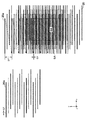
図2は、1つのサブアレイ5aによって分割された4×4本の荷電粒子線の走査における基板上での軌跡を示す図である。図2(a)は、4×4本の荷電粒子線を偏向器アレイ8によってX方向に1回偏向したときに、各荷電粒子線が描画する基板上の領域20を示す図である。図2(b)は、4×4本の荷電粒子線が、偏向器アレイ8による荷電粒子線の偏向とステージ11による基板10の移動とによって描画することができる範囲(ストライプ領域SA)を示す図である。図2では、各荷電粒子線が常に基板10に照射されるものとして説明するが、実際には、上述のように、ピッチGXで規定される画素ごとに各荷電粒子線のオンとオフとがブランカアレイ6により制御される。
FIG. 2 is a diagram showing a locus on the substrate in the scanning of 4 × 4 charged particle beams divided by one
図2(b)において、黒く塗りつぶされた領域20aは、サブアレイ5aに形成された開口5b1を通過した荷電粒子線が偏向器アレイ8で偏向されることにより描画される領域20を示している。開口5b1を通過した荷電粒子線は、最上部の領域20aを描画した後、破線の矢印で示すように、−X方向へのフライバックおよび−Y方向へのステージ11の移動(距離DP)を介して領域20aを順次描画していく。このとき、開口5b1以外の開口5bを通過した荷電粒子線も、開口5b1を通過した荷電粒子線と同様に基板10を描画していく。これにより、ストライプ幅SWを有するストライプ領域SAを、図2において破線で示すように、各荷電粒子線によって描画される各領域24によって埋め尽くすことができる。即ち、描画装置100は、ステージ11の連続移動と、偏向器アレイ8による荷電粒子線の偏向とを繰り返すによって、ストライプ領域SAを描画することができる。このストライプ領域SAが、1つのサブアレイ5aを通過した複数の荷電粒子線によって描画可能となる基板上の領域である。
In FIG. 2 (b), blackened
図3は、対物レンズアレイ9の各対物レンズOLとストライプ領域SAとの位置関係を示す図である。上述したように、1つのストライプ領域SAは、1つのサブアレイ5aによって分割された複数の荷電粒子線によって描画することができる基板上の領域である。また、1つのサブアレイ5aによって分割された複数の荷電粒子線は、対物レンズアレイ9における1つの対物レンズOLを通過する。対物レンズアレイ9は、例えば、図3に示すように、X方向に130μmのピッチで配列した複数の対物レンズOLをそれぞれ有する複数の列が、ストライプ幅SWである2μmだけX方向に互いにずれながらY方向に並ぶように構成される。このように対物レンズアレイ9を構成することによって、複数のストライプ領域SAを隙間なく配置することができる。対物レンズアレイ9は、図3では4×8個の対物レンズOLによって構成されているが、実際には、例えば、65×200個といった多くの対物レンズOLによって構成されうる。このような構成によれば、ステージ11をY方向に沿った一方向に連続移動させることにより、描画領域EAで基板上に描画を行うことができる。
FIG. 3 is a diagram showing a positional relationship between each objective lens OL of the
次に、ブランカアレイ6における各荷電粒子線の偏向について図4を参照しながら説明する。図4は、1つのサブアレイ5a(例えば4×4個の開口5bを有する)によって分割された複数の荷電粒子線を個別に偏向する複数のブランカ6aの構成を示す図である。複数のブランカ6aには、例えば、ブランキング制御器12から制御データを示す信号が光信号60として供給される。供給された光信号60は、フォトダイオード61(PD)によって受光され、電気信号としてトランスファーインピーダンスアンプ62(TIA)に供給される。TIAに供給された信号は、TIAにおいて電流−電圧変換され、リミッティングアンプ63(LA)において振幅が調整される。振幅調整された信号はシフトレジスタ64に入力され、ブランカに電圧を印加するための信号(パラレル信号)に変換される。X方向に延びるゲート電極線69aおよびY方向に延びるソース電極線69bは、それらが交わる点に配置されたFET67のゲート電極およびソース電極にそれぞれ接続されている。FET67のドレイン電極には、ブランカ6aおよびコンデンサ68がそれぞれ1つずつ並列に接続され、これら2つの素子の反対側は接地されている。
Next, deflection of each charged particle beam in the
例えば、ゲートドライバ66が1本のゲート電極線69aに信号(電圧)を供給すると、そのゲート電極線69aに接続されている1行分すべてのFET67がON動作する。このとき、ソース電極線69bに加えられている各電圧がブランカ6aに印加されるとともに、ON動作しているFET67に接続されたコンデンサ68に、ソース電極線に加えられている電圧に応じた電荷が蓄積(充電)される。ゲートドライバ66は、1行分のコンデンサ68の充電を終えると、電圧を印加するゲート電極線69aを切り換える。このとき、当該1行分のブランカ6aは、ソース電極線69bからの電圧を失うが、コンデンサ68に蓄積された電荷によって、次に電圧が印加されるまでの間は必要な電圧を維持できるようになっている。このようにFET67をスイッチとして用いたアクティブ・マトリクス駆動方式によれば、ゲート電極線69aおよびソース電極線69bによって並行して多数のブランカ6aに電圧を印加することができる。そのため、ブランカ6aの多数化に少ない配線数で対応することができる。ここで、図4の例では、ブランカ6aは4行4列に配列されている。シフトレジスタ64からのパラレル信号は、データドライバ65およびソース電極線69bを介して、FET67のソース電極に電圧として印加される。これと協働して、ゲートドライバ66から印加される電圧により、1行分のFET67がON動作するため、それに接続された1行分のブランカ6aが制御される。このような動作が各行に対して順次繰り返されることにより4行4列のブランカ6aを制御することができる。
For example, when the
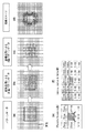
図5は、空間変調方式の描画方法を説明するための図である。以下の説明において、1つの画素に照射される荷電粒子線のドーズを「10」とし、1つの画素におけるドーズの目標値の最大を「8」としている。図5(a)は、描画装置100の走査グリッド上に、基板上に描画されるべきパターンを規定する設計データ(パターンデータ)を配置した図である。図5(a)に示すパターンデータは、0.25nmピッチの設計グリッド点で設計された20nm×20nmの正方形とした。走査グリッドでは画素間のピッチが2.5nmであり、設計グリッドのピッチのピッチより大きいため、同図に示すようにパターンデータを走査グリッド上で忠実に表現することができない。そこで、制御部100bは、各画素におけるパターンデータの面積密度を計算し、その面積密度に基づいて各画素のドーズ(線量、露光量)に関する目標値を決定する。即ち、制御部100bは、パターンデータを用いて、荷電粒子線が照射される画素に対するパターンが占める割合(パターンの占有率)に応じて荷電粒子線のドーズに関する目標値を決定する。これにより、制御部100bは、図5(b)に示すように、各画素における荷電粒子線のドーズに関する目標値を表す多値パターンデータを生成することができる。
FIG. 5 is a diagram for explaining a spatial modulation drawing method. In the following description, the dose of the charged particle beam irradiated to one pixel is “10”, and the maximum target value of the dose in one pixel is “8”. FIG. 5A is a diagram in which design data (pattern data) defining a pattern to be drawn on the substrate is arranged on the scanning grid of the
そして、制御部100bは、各画素における荷電粒子線のオンまたはオフを示す指令値を生成するため、例えば誤差拡散法を用いて、多値パターンデータを二値パターンデータに変換する。例えば、制御部100bは、図5(b)の多値パターンデータの各画素に対して、各画素における目標値の値が閾値(例えば「5」)より小さければその画素における指令値を「0」に設定し、閾値以上であればその画素における指令値を「10」に設定する。即ち、指令値が「0」に設定された画素では荷電粒子線がオフにされ、指令値が「10」に設定された画素では荷電粒子線がオンにされる。そして、制御部100bは、指令値と目標値との誤差を、図5(e)に示す誤差拡散カーネルによって定められた比率で周囲の画素に分配する。制御部100bは、これらの処理を、左上の画素から初めて右下の画素に至るまでラスター走査の順に繰り返すことにより、図5(c)に示すように、二値パターンデータを生成することができる。図5(d)は、図5(c)に示す二値パターンデータに基づいて荷電粒子線のオンまたはオフを制御して描画された描画イメージを示す図である。ここで、荷電粒子線のビーム径は、2.5nm×2.5nmの画素に比べて十分大きくし、グリッド上の粗密のパターンを平滑化している。また、制御部100bは、図5(e)に示すFloyd&Steinberg型の誤差拡散法のカーネルを用いて二値化を行ったが、それに限られるものではない。例えば、図5(f)に示すJarvis,Judice&Ninke型の誤差拡散法など他のカーネルを用いてもよい。
Then, the
図6は、各画素におけるドーズの指令値と各画素に実際に照射されるドーズ(実ドーズ)との関係の一例を示す図である。指令値は、二値パターンデータによって規定された各画素における荷電粒子線のオンまたはオフを示しており、「0」または「10」によって表される。上述したように、「0」に設定された画素では荷電粒子線がオフにされ、「10」に設定された画素では荷電粒子線がオンにされる。図6では、1ライン分の二値パターンデータを示している。 FIG. 6 is a diagram illustrating an example of a relationship between a command value of dose in each pixel and a dose (actual dose) actually applied to each pixel. The command value indicates ON or OFF of the charged particle beam in each pixel defined by the binary pattern data, and is represented by “0” or “10”. As described above, the charged particle beam is turned off in the pixel set to “0”, and the charged particle beam is turned on in the pixel set to “10”. FIG. 6 shows binary pattern data for one line.
制御部100bは、二値パターンデータに従ってブランカアレイ6を制御する。例えば、指令値が「10」に設定されている画素ではブランカ6aにおける2枚の電極に電圧が印加されず、荷電粒子線が、ブランカ6aで偏向されずにブランキングアパーチャ7を通過して基板10に照射される。一方で、指令値が「0」に設定されている画素ではブランカ6aにおける2枚の電極に電圧が印加され、荷電粒子線が、ブランカ6aで偏向されてブランキングアパーチャ7で遮断され、基板10に照射されない。このようにブランカ6aによって荷電粒子線のオンとオフとを切り換える際、ブランカ6aに並列に接続されたコンデンサ68に電荷が蓄積されるまでに時間を要し、ブランカ6aによって荷電粒子線が偏向されるまでに応答遅れが生じうる。即ち、ブランカ6aは、荷電粒子線のオンとオフとを切り替えるときに動作遅延が生じるような動作特性(伝達特性)を有し、ブランカに指令値が供給されてから荷電粒子線のオンとオフとが切り替わるまでに時間を要しうる。そのため、荷電粒子線のオンとオフとを切り換えるようにブランカに指令を与えた直後の画素では荷電粒子線の基板10への照射強度が緩やかになる。その結果、当該画素に照射される予定のドーズ(指令値)と当該画素に実際に照射されるドーズ(実ドーズ)との間に差が生じうる。
The
例えば、図6に示す左から3番目の画素のように、荷電粒子線をオフからオンに切り替えるようにブランカに指令を与えた直後に荷電粒子線を照射させる画素を想定する。この場合、左から3番目の画素には、指令値に従うと「10」のドーズが得られる予定である。しかしながら、実際には、ブランカ6aの動作遅延により、当該画素には「6」のドーズしか得ることができない。また、図6に示す左から6番目の画素のように、荷電粒子線をオンからオフに切り換えるようにブランカに指令を与えた直後に荷電粒子線を照射させない画素を想定する。この場合、左から6番目の画素には、指令値に従うと「0」のドーズとなる予定である。しかしながら、実際には、ブランカ6aの動作遅延により、当該画素には「4」のドーズが得られてしまう。 For example, a pixel that is irradiated with a charged particle beam immediately after giving a command to the blanker to switch the charged particle beam from off to on is assumed as in the third pixel from the left shown in FIG. In this case, a dose of “10” will be obtained for the third pixel from the left according to the command value. However, in practice, only a dose of “6” can be obtained for the pixel due to the operation delay of the blanker 6a. Further, a pixel that is not irradiated with a charged particle beam immediately after a command is given to the blanker to switch the charged particle beam from on to off is assumed, as in the sixth pixel from the left shown in FIG. In this case, the sixth pixel from the left is scheduled to have a dose of “0” according to the command value. However, in practice, a “4” dose is obtained for the pixel due to the operation delay of the blanker 6a.
また、各画素に照射される予定のドーズと各画素に実際に照射されるドーズとの差は、それまでの荷電粒子線の制御履歴によって変動する。荷電粒子線のオンとオフとの切り換え(状態遷移)が連続している場合、ブランカ6aに印加される電圧は最大値まで到達しない状態で遷移が起こるため、各画素の照射される予定のドーズと実際のドーズとの差はさらに大きくなりうる。例えば、図6に示す左から10番目の画素に注目する。この10番目の画素では指令値が「0」であり、1つ前の画素(9番目の画素)では指令値が「10」であり、2つ前の画素(9番目の画素)では指令値が「0」である。即ち、荷電粒子線の状態遷移が連続して生じている。この場合、9番目の画素においてはブランカ6aの動作遅延により「6」のドーズとなるとともに、ブランカ6aに印加される電圧が最大値まで到達しない。そのため、10番目の画素においては、荷電粒子線の照射強度を最大になる前に低下させるため、「0」のドーズとなる予定が、「2」のドーズとなる。同様に、図6に示す左から15番目の画素に注目する。この15番目の画素では指令値が「10」であり、1つ前の画素(14番目の画素)では指令値が「0」であり、2つ前の画素(13番目の画素)では指令値が「10」である。即ち、荷電粒子線の状態遷移が連続して生じうる。この場合、14番目の画素においてはブランカ6aの動作遅延により「4」のドーズとなるとともに、ブランカ電圧が最小値まで到達しない。そのため、15番目の画素においては、荷電粒子線の照射強度を最小となる前に増加させるため、「10」のドーズとなる予定であるが、「8」のドーズが得られることとなる。
Further, the difference between the dose to be irradiated to each pixel and the dose to be actually irradiated to each pixel varies depending on the charged particle beam control history so far. When the charged particle beam is continuously switched on and off (state transition), the voltage applied to the blanker 6a transitions in a state where the voltage does not reach the maximum value. And the actual dose can be even greater. For example, focus on the tenth pixel from the left shown in FIG. The command value is “0” for the tenth pixel, the command value is “10” for the previous pixel (the ninth pixel), and the command value is for the second previous pixel (the ninth pixel). Is “0”. That is, the state transition of the charged particle beam occurs continuously. In this case, the ninth pixel has a dose of “6” due to the operation delay of the blanker 6a, and the voltage applied to the
このように荷電粒子線のオンとオフとを切り換えるときにブランカ6aに動作遅延が生じる場合、その直後では、画素に照射される予定のドーズ(指令値)と当該画素に実際に照射されるドーズ(実ドーズ)との間に差が生じうる。そのため、従来の描画装置のように荷電粒子線のドーズに関する目標値と指令値との誤差を拡散させる方法では、当該誤差が、対象画素に実際に照射される荷電粒子線のドーズの値と目標値との誤差と異なりうる。即ち、従来の描画装置では、対象画素に実際に照射される荷電粒子線のドーズの値と目標値との誤差とは異なる誤差を、対象画素の後に荷電粒子線の照射が行われる画素に拡散させていた。その結果、基板10にパターンを精度よく形成することが不十分であった。そこで、第1実施形態の描画装置100では、制御部100bは、複数の画素のうち対象画素において目標値を二値化して指令値を決定する。制御部100bは、対象画素に照射される荷電粒子線のドーズを、ブランカ6aの動作遅延を考慮して、対象画素の前に荷電粒子線が照射される画素(第1画素)の指令値および対象画素の指令値に基づいて予測する。そして、制御部100bは、対象画素の荷電粒子線のドーズに関する目標値と予測値との差を対象画素の後に荷電粒子線を照射する画素(第2画素)の目標値に拡散させる。
In this manner, when an operation delay occurs in the blanker 6a when switching the charged particle beam on and off, immediately after that, a dose (command value) to be irradiated to the pixel and a dose actually irradiated to the pixel. There may be a difference with (real dose). For this reason, in the method of diffusing the error between the target value and the command value related to the charged particle beam dose as in the conventional drawing apparatus, the error corresponds to the dose value of the charged particle beam actually irradiated onto the target pixel and the target value. It may be different from the error from the value. That is, in the conventional drawing apparatus, an error different from the error between the dose value of the charged particle beam actually irradiated to the target pixel and the target value is diffused to the pixel to be irradiated with the charged particle beam after the target pixel. I was letting. As a result, it was insufficient to form a pattern on the
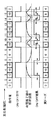
図7は、第1実施形態の描画装置100におけるデータフローを示す図である。パターンデータは、パターンデータメモリに記憶されたベクタ形式の設計データ(26mm×33mm内に収まるショット領域に対応するパターンデータ)である。
FIG. 7 is a diagram illustrating a data flow in the
(1)準備処理
まず、データ変換器17において、パターンデータ101を中間データ103に変換する変換処理102が行われる。データ変換器17は、パターンデータ101に対して近接効果補正を行うとともに、パターンデータ101の諧調を変更する。近接効果補正が行われたデータは、ストライプ描画領域SAに対応したストライプ単位に分割される。本実施形態では、隣り合う荷電粒子線で二重描画(二重露光)してスティッチングを行うため、両端それぞれに幅0.1μmの重複領域を付加して幅2.2μmの中間データ103を生成する(隣り合う中間データの重複部分は、同一のデータとしうる)。
(1) Preparation Process First, the
(2)多値化処理
以下に、描画装置100に基板10が投入された後のフローについて説明する。制御部100bにおいて、主制御器19は、中間データメモリ18から中間データ103をデータ処理器13に転送させる。データ処理器13は、転送された中間データ103をストライプ単位の多値パターンデータ(DATA104)としてそれぞれ記憶する。多値パターンデータは、各画素における荷電粒子線のドーズに関する目標値を表すデータである。ここで、ベクタ形式の中間データ103は、描画装置100のグリッド座標系での多値パターンデータに変換される。具体的には、例えば、各画素における中間データの面積密度や、各ストライプを描画する荷電粒子線の照射強度に基づく補正係数、二重描画領域でのドーズ補正係数(基本的には0.5)に基づいて変換が行われうる。
(2) Multi-value processing A flow after the
(3)補正処理
データ処理器13は、描画と並行して、ストライプごとの多値パターンデータに対して以下の(3−1)から(3−3)に示す処理を含む補正処理105を行う。
(3) Correction Processing In parallel with drawing, the
(3−1)座標変換
基板上のショット領域に対して重ね合わせて描画を行うため、データ処理器13は、予め計測された基板上のショット領域の配置を求めるための情報(例えば、伸縮係数βr、回転係数θr、並進係数Ox・Oy)に基づいて式(1)の座標変換を行う。ここで、xおよびyは、補正前のストライプごとの多値パターンデータの座標を表し、x’およびy’は、補正後のストライプごとの多値パターンデータの座標を表す。また、OxおよびOyは、ストライプに対応した荷電粒子線の設計上の位置からの位置ずれを補正するためのオフセット量を含みうる。
(3-1) Coordinate conversion In order to perform superimposition on the shot area on the substrate for drawing, the

(3−2)二値化処理
上記の座標変換後の多値パターンデータを、誤差拡散法を用いて二値パターンデータ(荷電粒子線のオンまたはオフを示す指令値)に変換する処理について、図8を参照しながら説明する。この処理は、描画順に画素ごとおよび行ごとの繰り返しとなるため、以下の説明では、1つの画素(対象画素)に注目して説明する。
(3-2) Binarization process Regarding the process of converting the multi-value pattern data after the coordinate conversion into binary pattern data (command value indicating on or off of charged particle beam) using an error diffusion method. This will be described with reference to FIG. Since this process is repeated for each pixel and each row in the drawing order, the following description will be made by paying attention to one pixel (target pixel).
S91では、データ処理器13は、多値パターンデータを閾値と比較して二値化(量子化)を行い、対象画素において荷電粒子線のオンまたはオフを示す指令値を決定する。S92では、データ処理器13は、対象画素の前に荷電粒子線が照射される第1画素において、荷電粒子線のオンとオフとの切り換え(状態遷移)を確認する。対象画素の前に荷電粒子線が照射される第1画素は、対象画素の1つ前に荷電粒子線が照射される画素を含む。また、第1画素は、対象画素の1つ前に荷電粒子線が照射される画素に加えて、対象画素の2つ前に荷電粒子線が照射される画素をさらに含んでもよい。S93では、データ処理器13は、第1画素の指令値および対象画素の指令値に基づき、ブランカ6aの動作遅延を考慮して、対象画素に照射される荷電粒子線のドーズを予測する。
In S91, the
対象画素に照射される荷電粒子線のドーズの予測は、例えば、予め作成しておいたルックアップテーブルを参照して行われうる。当該ルックアップテーブルは、例えば図9に示すように、対象画素、対象画素の1つ前の画素、および対象画素の2つ前の画素における荷電粒子線の制御に対して、対象画素にどのくらいの荷電粒子線のドーズが得られるかの情報を有する。即ち、図9に示される情報は、対象画素、およびその前に荷電粒子線が照射される第1画素(対象画素の1つ前の画素、対象画素の2つ前の画素を含む)で指令値が変化する場合において、それらの指令値と対象画素におけるドーズとの関係を示す情報である。データ処理器13は、ルックアップテーブルを参照することにより、対象画素の照射される荷電粒子線のドーズを予測することができる。ルックアップテーブルは、例えば、ブランカ6aの動作遅延をシミュレーションや実験によって求めることにより作成されうる。ここで、より精度を向上させるため、ルックアップテーブルの作成にあたり、対象画素の3つ以上前の画素における荷電粒子線の制御も考慮してもよい。また、第1実施形態の描画装置100は、基板10の描画を開始する前に、ルックアップテーブルを参照して対象画素に照射される荷電粒子線のドーズを予測し、各画素に対する指令値を決定したが、それに限られるものではない。例えば、描画を行っている際にリアルタイムに計算して対象画素におけるドーズを予測して指令値を決定してもよい。
The prediction of the dose of the charged particle beam irradiated to the target pixel can be performed with reference to a lookup table prepared in advance, for example. For example, as shown in FIG. 9, the look-up table shows how much the target pixel is in control of the charged particle beam in the target pixel, the pixel immediately before the target pixel, and the pixel immediately before the target pixel. It has information on whether the dose of a charged particle beam can be obtained. That is, the information shown in FIG. 9 is specified by the target pixel and the first pixel to which the charged particle beam is irradiated before (including the pixel one pixel before the target pixel and the pixel two pixels before the target pixel). This is information indicating the relationship between the command value and the dose in the target pixel when the value changes. The
S94では、データ処理器13は、荷電粒子線のドーズに関する目標値(多値パターンデータ)と予測値との差(予測値誤差)を求める。S95では、データ処理器13は、S94で求めた差を、対象画素の後に荷電粒子線を照射する画素の目標値に拡散させる。S96では、データ処理器13は、すべての画素について指令値を決定したか否かを判断する。すべての画素について指令値が決定されている場合には、データ処理器13は指令値を生成する処理を終了する。一方で、すべての画素について指令値が決定されていない場合には、データ処理器13は、S91に戻り、対象画素における目標値と予測値との差が拡散された第2画素の目標値から、第2画素の指令値を決定する。
In S94, the
ここで、各画素におけるドーズの誤差の算出について、図10を参照しながら説明する。図10は、各画素におけるドーズの誤差の算出を説明するための図である。例えば、図10に示す左から3番目の画素を対象画素とする場合を想定する。この場合、データ処理器13は、対象画素において、荷電粒子線のドーズに関する目標値(多値パターンデータ)である「5」と、ブランカの動作遅延を考慮して予測された荷電粒子線のドーズの予測値である「6」との差「−1」を求める。そして、データ処理器13は、求めた差「−1」を第2画素の目標値に拡散させる。従来の描画装置では、ブランカの動作遅延が考慮されておらず、荷電粒子線のドーズに関する目標値「5」と指令値「10」との差(量子化誤差)「−5」が第2画素に拡散されていた。即ち、従来では、ブランカ6aの動作遅延が生じているときに実際に生じる誤差(予測値誤差)より大きい誤差が第2画素に拡散されていた。第1実施形態の描画装置100は、ブランカ6aの動作遅延を考慮して対象画素に照射される荷電粒子線のドーズを予測し、荷電粒子線のドーズに関する目標値と予測値との差を第2画素に拡散させる。このように誤差拡散を行って各画素の指令値を求め、当該指令値に従って荷電粒子線のオンまたはオフを制御することで、基板にパターンを精度よく形成することができる。
Here, calculation of a dose error in each pixel will be described with reference to FIG. FIG. 10 is a diagram for explaining calculation of a dose error in each pixel. For example, assume that the third pixel from the left shown in FIG. 10 is the target pixel. In this case, in the target pixel, the
(3−3)シリアルデータ変換
データ処理器13は、各画素について二値化されたデータ(指令値)を、荷電粒子線ごとおよび描画順にソートしてブランカの制御データ106を生成する。このようにして生成された制御データ106は、逐次ブランキング制御器12に送られ、ブランキング制御器12によってブランカアレイ6に供給される。
(3-3) Serial Data Conversion The
上述したように、第1実施形態の描画装置100は、ブランカ6aの動作遅延を考慮して対象画素に照射される荷電粒子線のドーズを予測し、対象画素の荷電粒子線のドーズに関する目標値と予測値との差を求める。そして、描画装置100は、求めた差を、対象画素の後に荷電粒子線が照射される画素の目標値に拡散させる。このように誤差拡散を行うことにより、基板10に描画されたパターンの位置ずれやボケ(例えば線幅の細り)を低減し、基板10にパターンを精度よく形成することができる。
As described above, the
<物品の製造方法の実施形態>
本発明の実施形態における物品の製造方法は、例えば、半導体デバイス等のマイクロデバイスや微細構造を有する素子等の物品を製造するのに好適である。本実施形態の物品の製造方法は、上記のリソグラフィ装置(描画装置)を用いて基板にパターンを形成する工程(基板に描画を行う工程)と、かかる工程でパターンが形成された基板を加工する工程とを含む。更に、かかる製造方法は、他の周知の工程(酸化、成膜、蒸着、ドーピング、平坦化、エッチング、レジスト剥離、ダイシング、ボンディング、パッケージング等)を含む。本実施形態の物品の製造方法は、従来の方法に比べて、物品の性能・品質・生産性・生産コストの少なくとも1つにおいて有利である。
<Embodiment of Method for Manufacturing Article>
The method for manufacturing an article according to an embodiment of the present invention is suitable for manufacturing an article such as a microdevice such as a semiconductor device or an element having a fine structure. The article manufacturing method of this embodiment uses the above-described lithography apparatus (drawing apparatus) to form a pattern on a substrate (a process of drawing on the substrate), and to process the substrate on which the pattern is formed in the process. Process. Further, the manufacturing method includes other well-known steps (oxidation, film formation, vapor deposition, doping, planarization, etching, resist stripping, dicing, bonding, packaging, and the like). The method for manufacturing an article according to this embodiment is advantageous in at least one of the performance, quality, productivity, and production cost of the article as compared with the conventional method.
以上、本発明の好ましい実施形態について説明したが、本発明はこれらの実施形態に限定されないことはいうまでもなく、その要旨の範囲内で種々の変形および変更が可能である。 As mentioned above, although preferred embodiment of this invention was described, it cannot be overemphasized that this invention is not limited to these embodiment, A various deformation | transformation and change are possible within the range of the summary.
例えば、以上の説明において、ブランカアレイ6は、個別に駆動可能な電極対のアレイを含むものとして例示したが、それには限定されず、ブランキング機能を有する素子のアレイであればよい。例えば、ブランカアレイ6は、米国特許第7816655号明細書に記載されているように、荷電粒子線を選択的に反射する反射性電子パターニングデバイス(reflective electron patterning device)を含みうる。当該デバイスは、上面(top surface)上のパターンと、該パターンのうちの電子反射部分と、該パターンのうちの電子非反射部分とを含む。当該デバイスは、さらに、独立に制御可能な複数の画素を用いて上記パターンのうちの電子反射部分および電子非反射部分を動的に変更するための回路アレイ(array of circuitry)を含む。このように、ブランカアレイは、荷電粒子線に対する反射部分を非反射部分に変更することにより荷電粒子線のブランキングを行う素子(ブランカ)のアレイであってもよい。なお、そのような反射性デバイスを備える荷電粒子光学系の構成と電極対アレイのような荷電粒子線を選択的に透過する透過性デバイスを備える荷電粒子光学系の構成とが互いに異なりうるのは当然である。
For example, in the above description, the
100:描画装置、100a:描画部、100b:制御部、10:基板、6:ブランカアレイ、8:偏向器アレイ 100: Drawing apparatus, 100a: Drawing unit, 100b: Control unit, 10: Substrate, 6: Blanker array, 8: Deflector array
Claims (10)
前記ビームのブランキングを行うブランカと、
前記ブランカを制御する制御部と、を含み、
前記制御部は、前記基板上の複数の画素のそれぞれに対して誤差の拡散を伴う量子化を順に行って前記ブランキングの指令値を生成し、
前記誤差は、前記複数の画素のうちの対象画素における線量の目標値と線量の予測値との間の誤差であることを特徴とするリソグラフィ装置。 A lithographic apparatus for forming a pattern on a substrate with a beam,
A blanker for blanking the beam;
A control unit for controlling the blanker,
The control unit sequentially performs quantization with error diffusion for each of the plurality of pixels on the substrate to generate the blanking command value,
The lithographic apparatus, wherein the error is an error between a target dose value and a predicted dose value in a target pixel of the plurality of pixels.
前記工程で前記パターンの形成を行われた前記基板を加工する工程と、
を含むことを特徴とする物品の製造方法。 Forming a pattern on a substrate using the lithographic apparatus according to claim 1;
Processing the substrate on which the pattern has been formed in the step;
A method for producing an article comprising:
Priority Applications (2)
| Application Number | Priority Date | Filing Date | Title |
|---|---|---|---|
| JP2014085883A JP2015207608A (en) | 2014-04-17 | 2014-04-17 | Lithographic apparatus and method of manufacturing article |
| US14/685,704 US20150303025A1 (en) | 2014-04-17 | 2015-04-14 | Lithography apparatus, and method of manufacturing an article |
Applications Claiming Priority (1)
| Application Number | Priority Date | Filing Date | Title |
|---|---|---|---|
| JP2014085883A JP2015207608A (en) | 2014-04-17 | 2014-04-17 | Lithographic apparatus and method of manufacturing article |
Publications (1)
| Publication Number | Publication Date |
|---|---|
| JP2015207608A true JP2015207608A (en) | 2015-11-19 |
Family
ID=54322602
Family Applications (1)
| Application Number | Title | Priority Date | Filing Date |
|---|---|---|---|
| JP2014085883A Pending JP2015207608A (en) | 2014-04-17 | 2014-04-17 | Lithographic apparatus and method of manufacturing article |
Country Status (2)
| Country | Link |
|---|---|
| US (1) | US20150303025A1 (en) |
| JP (1) | JP2015207608A (en) |
Cited By (1)
| Publication number | Priority date | Publication date | Assignee | Title |
|---|---|---|---|---|
| JP2018073916A (en) * | 2016-10-26 | 2018-05-10 | 株式会社ニューフレアテクノロジー | Multi-charge-particle beam lithography device and multi-charge-particle beam lithography method |
Families Citing this family (1)
| Publication number | Priority date | Publication date | Assignee | Title |
|---|---|---|---|---|
| JP2015211175A (en) * | 2014-04-28 | 2015-11-24 | キヤノン株式会社 | Lithographic apparatus and manufacturing method of article |
Family Cites Families (2)
| Publication number | Priority date | Publication date | Assignee | Title |
|---|---|---|---|---|
| US7816655B1 (en) * | 2004-05-21 | 2010-10-19 | Kla-Tencor Technologies Corporation | Reflective electron patterning device and method of using same |
| JP5801288B2 (en) * | 2009-05-20 | 2015-10-28 | マッパー・リソグラフィー・アイピー・ビー.ブイ. | Method for generating a two-level pattern for lithographic processing and pattern generator using the method |
-
2014
- 2014-04-17 JP JP2014085883A patent/JP2015207608A/en active Pending
-
2015
- 2015-04-14 US US14/685,704 patent/US20150303025A1/en not_active Abandoned
Cited By (2)
| Publication number | Priority date | Publication date | Assignee | Title |
|---|---|---|---|---|
| JP2018073916A (en) * | 2016-10-26 | 2018-05-10 | 株式会社ニューフレアテクノロジー | Multi-charge-particle beam lithography device and multi-charge-particle beam lithography method |
| JP7002837B2 (en) | 2016-10-26 | 2022-01-20 | 株式会社ニューフレアテクノロジー | Multi-charged particle beam drawing device and multi-charged particle beam drawing method |
Also Published As
| Publication number | Publication date |
|---|---|
| US20150303025A1 (en) | 2015-10-22 |
Similar Documents
| Publication | Publication Date | Title |
|---|---|---|
| US9437396B2 (en) | Multi charged particle beam writing apparatus, and multi charged particle beam writing method | |
| JP4843248B2 (en) | Improved pattern definition apparatus for particle beam exposure. | |
| US9601315B2 (en) | Multiple charged particle beam lithography apparatus and multiple charged particle beam pattern writing method | |
| US6433348B1 (en) | Lithography using multiple pass raster-shaped beam | |
| KR100416131B1 (en) | Raster shaped beam, electron beam exposure strategy using a two dimensional multpixel flash field | |
| KR100417906B1 (en) | Flash converter for determining shape data that specifies a flash field among pixels, and method thereof | |
| JP2011523786A (en) | Method and system for exposing a target | |
| KR101782337B1 (en) | Charged particle beam writing apparatus and charged particle beam writing method | |
| JP6653125B2 (en) | Multi charged particle beam writing method and multi charged particle beam writing apparatus | |
| JP2019033117A (en) | Multi-charged particle beam lithography device and multi-charged particle beam lithography method | |
| JP2010073918A (en) | Charged particle beam drawing apparatus and method | |
| JP6577787B2 (en) | Multi-charged particle beam writing apparatus and multi-charged particle beam writing method | |
| JP2019029575A (en) | Multiple charged particle beam lithography apparatus and multiple charged particle beam lithography method | |
| JP6428518B2 (en) | Data generation apparatus, energy beam drawing apparatus, and energy beam drawing method | |
| JP2016207815A (en) | Charged particle beam lithography apparatus and charged particle beam lithography method | |
| JP6128744B2 (en) | Drawing apparatus, drawing method, and article manufacturing method | |
| JP2015211175A (en) | Lithographic apparatus and manufacturing method of article | |
| JP6541999B2 (en) | Multi-charged particle beam drawing apparatus and multi-charged particle beam drawing method | |
| JP2018073916A (en) | Multi-charge-particle beam lithography device and multi-charge-particle beam lithography method | |
| JP2017220491A (en) | Multi-charged-particle-beam exposure method and multi-charged-particle-beam exposure apparatus | |
| JP2014082289A (en) | Drawing device, and method of manufacturing article | |
| US7173262B2 (en) | Charged particle beam exposure apparatus, charged particle beam exposure method and device manufacturing method | |
| US9001387B2 (en) | Drawing apparatus, data processing method, and method of manufacturing article that transform partially overlapping regions using different transformation rules | |
| JP2015207608A (en) | Lithographic apparatus and method of manufacturing article | |
| KR20040005951A (en) | Raster shaped beam, electron beam exposure strategy using a two dimensional multiplexel flash field |