JP2015194056A - sash - Google Patents
sash Download PDFInfo
- Publication number
- JP2015194056A JP2015194056A JP2014073386A JP2014073386A JP2015194056A JP 2015194056 A JP2015194056 A JP 2015194056A JP 2014073386 A JP2014073386 A JP 2014073386A JP 2014073386 A JP2014073386 A JP 2014073386A JP 2015194056 A JP2015194056 A JP 2015194056A
- Authority
- JP
- Japan
- Prior art keywords
- shape
- outdoor
- indoor
- cross
- sash
- Prior art date
- Legal status (The legal status is an assumption and is not a legal conclusion. Google has not performed a legal analysis and makes no representation as to the accuracy of the status listed.)
- Granted
Links
Images



Landscapes
- Wing Frames And Configurations (AREA)
- Special Wing (AREA)
Abstract
【課題】効率よく室内外を断熱でき、室内の結露を防止できるとともに、室内外の温度差による召合内框の室内側形材の反りを防止できるサッシを提供する。
【解決手段】室外13側に位置する室外側形材4Aと、室内14側に位置する室内側形材5Aと、室外側形材4Aと室内側形材5Aとの間に設けられて室外側形材4Aと室内側形材5Aとを連結する断熱ブリッジ材6A,6Bと、を有する召合内框33Aを備え、室外側形材4Aの断面形状が、室内側形材5Aの断面形状よりも小さいことを特徴とする。
【選択図】図3Provided is a sash that can efficiently insulate indoors and outdoors, prevent dew condensation in the room, and prevent warping of the indoor side shape of the summit inner wall due to a temperature difference between the room and the outside.
An outdoor side profile 4A located on the outdoor 13 side, an indoor side profile 5A located on the indoor 14 side, and an outdoor side provided between the outdoor profile 4A and the indoor side profile 5A. A cross-sectional shape of the outdoor shape 4A is provided from the cross-sectional shape of the indoor side shape 5A. The cross section of the outdoor shape 4A is provided with a summing inner rod 33A having a heat insulating bridge material 6A, 6B for connecting the shape 4A and the indoor shape 5A. Is also small.
[Selection] Figure 3
Description
本発明は、引違い窓や上げ下げ窓のように召合框を有するサッシに関する。 TECHNICAL FIELD The present invention relates to a sash having a summon bowl such as a sliding window and a raising / lowering window.
従来、引違い窓や上げ下げ窓の召合框のうち室内側に位置する召合内框は、室外側に位置する室外側形材と、室内側に位置する室内側形材との間に断熱ブリッジ材が設けられている(例えば、特許文献1および2参照)。このような召合内框は、室外側形材および室内側形材がアルミニウムなどの金属を材料として形成され、断熱ブリッジ材がアルミニウムなどの金属よりも熱伝導率の小さい樹脂などを材料として形成されている。
そして、断熱ブリッジ材によって、室外の冷気が室外側形材から室内側形材へ伝導することを抑制し、室内外を断熱できるとともに、室内の結露を防止できる。
Conventionally, among the summits of the sliding window and the raising / lowering window, the summit inner wall located on the indoor side is thermally insulated between the outdoor shape located on the outdoor side and the indoor shape located on the indoor side. A bridge member is provided (see, for example,
And by the heat insulation bridge | bridging material, it can suppress that the cool air of an outdoor is transmitted from an outdoor shape to an indoor shape, can heat indoors and the outdoors, and can prevent indoor dew condensation.
しかしながら、召合内框は、室内外の温度差が大きいと、室外側形材が室外の冷気によって冷やされて収縮し、室内側形材が室内の暖気によって温められて膨張するため、室内側形材に反りが生じる虞がある。
そして、室内側形材に反りが生じることにより、室外側形材と室内側形材とが位置ずれし、召合内框の内部に室内外の空気の流路が形成されてしまう虞がある。
However, if the temperature inside and outside of the summit is large, the outdoor shape is cooled and contracted by the outdoor cold air, and the indoor side material is heated and expanded by the indoor warm air. There is a risk of warping of the profile.
Further, when the indoor shape is warped, the outdoor shape and the indoor shape are displaced from each other, and there is a possibility that an indoor and outdoor air flow path is formed inside the summit inner wall. .
そこで、本発明は、効率よく室内外を断熱でき、室内の結露を防止できるとともに、室内外の温度差による召合内框の室内側形材の反りを防止できるサッシを提供することを目的とする。 SUMMARY OF THE INVENTION An object of the present invention is to provide a sash that can efficiently insulate indoors and outdoors, prevent indoor dew condensation, and prevent warping of the indoor side shape of the summit inner wall due to a temperature difference between indoors and outdoors. To do.
上記目的を達成するため、本発明に係るサッシは、室外側に位置する室外側形材と、室内側に位置する室内側形材と、前記室外側形材と前記室内側形材との間に設けられて前記室外側形材と前記室内側形材とを連結する断熱ブリッジ材と、を有する召合内框を備え、 前記室外側形材の断面形状が、前記室内側形材の断面形状よりも小さいことを特徴とする。 In order to achieve the above object, a sash according to the present invention includes an outdoor shape located on the outdoor side, an indoor shape located on the indoor side, and between the outdoor shape and the indoor shape. A heat-insulating bridging member provided with a heat insulating bridge member connecting the outdoor-side profile and the indoor-side profile, wherein a cross-sectional shape of the outdoor-side profile is a cross-section of the indoor-side profile. It is smaller than the shape.
本発明では、室外側形材の断面形状が、室内側形材の断面形状よりも小さいことにより、室内外の温度差によって室外側形材が膨張し、室内側形材が収縮する際に、室外側形材が膨張する力の方が、室内側形材が収縮する力よりも大きくなるため、室外側形材の膨張に室内側形材を追従させることができる。これにより、室外側形材が反ることを防止できる。
また、室外側形材の断面形状が、室内側形材の断面形状よりも小さいことにより、室内側形材の断面形状と室外側形材の断面形状とが同じ場合や、室外側形材の断面形状が室内側形材の断面形状よりも大きい場合と比べて、室外の冷温が室外側形材を介して室内側形材へ伝わりにくい構造となるため、召合内框において効率よく室内外を断熱できるとともに、室内の結露を防止できる。
In the present invention, when the cross-sectional shape of the outdoor shape is smaller than the cross-sectional shape of the indoor side shape, the outdoor shape expands due to a temperature difference between the indoor and outdoor, and the indoor side shape shrinks. Since the force with which the outdoor shape member expands is larger than the force with which the indoor shape member contracts, the indoor shape member can follow the expansion of the outdoor shape member. Thereby, it can prevent that an outdoor shape member warps.
In addition, because the cross-sectional shape of the outdoor shape is smaller than the cross-sectional shape of the indoor shape, the cross-sectional shape of the indoor shape and the cross-sectional shape of the outdoor shape are the same. Compared to the case where the cross-sectional shape is larger than the cross-sectional shape of the indoor-side profile, the outdoor cold temperature is less likely to be transmitted to the indoor-side profile via the outdoor-side profile. Can be insulated and indoor condensation can be prevented.
また、本発明に係るサッシでは、前記室外側形材は、煙返し部であることが好ましい。
このような構成とすることにより、煙返し部である室外側形材の断面形状と、煙返し部以外となる室内側形材の断面形状との大きさの差を大きくできるため、室内外の温度差が大きく室内側形材が膨張した際に、この膨張に室外側形材をより追従させることができて、室内側形材が反ることを防止できる。
Moreover, in the sash which concerns on this invention, it is preferable that the said outdoor shape is a smoke return part.
By adopting such a configuration, the difference in size between the cross-sectional shape of the outdoor shape that is the smoke return portion and the cross-sectional shape of the indoor side shape other than the smoke return portion can be increased. When the indoor side shape member expands due to a large temperature difference, the outdoor side shape member can be made to follow the expansion, and the indoor side shape member can be prevented from warping.
また、本発明に係るサッシでは、前記断熱ブリッジ材は、前記室外側形材と前記室内側形材との間に複数設けられている構成としてもよい。
このような構成とすることにより、断熱ブリッジ材は、室外側形材と室内側形材との連結部分となるため、室外側形材と室内側形材とを確実に連結できる。
In the sash according to the present invention, a plurality of the heat insulating bridge members may be provided between the outdoor shape member and the indoor shape member.
By setting it as such a structure, since a heat insulation bridge material becomes a connection part of an outdoor shape and an indoor side shape, it can connect an outdoor shape and an indoor side shape reliably.
また、本発明に係るサッシでは、前記断熱ブリッジ材は、見込み方向に対して斜めに対向する前記室外側形材と前記室内側形材との間に設けられている構成としてもよい。
このような構成とすることにより、室外側形材の断面形状の大きさと室内側形材の断面形状の大きさとの差が大きく、また、室外側形材と室内側形材とが見込み方向に対向する部分が小さい場合も、室外側形材および室内側形材に見込み方向に対して斜めに対向する部分があれば断熱ブリッジ材を設けることができる。
Moreover, in the sash which concerns on this invention, the said heat insulation bridge | bridging material is good also as a structure provided between the said outdoor side shape material and the said indoor side shape material which diagonally oppose with respect to a prospect direction.
With such a configuration, the difference between the cross-sectional shape of the outdoor shape and the cross-sectional shape of the indoor shape is large, and the outdoor shape and the indoor shape are in the expected direction. Even when the facing portions are small, the heat insulating bridge material can be provided if the outdoor shape and the indoor shape have a portion that is diagonally opposed to the prospective direction.
また、本発明に係るサッシでは、アルミニウムと樹脂の複合サッシであることが好ましい。
このような構成とすることにより、アルミニウムと樹脂の複合サッシにおいても、室外側形材が反ることを防止できるとともに、召合内框において効率よく室内外を断熱できて、室内の結露を防止できる。
The sash according to the present invention is preferably a composite sash of aluminum and resin.
With such a configuration, even in a composite sash of aluminum and resin, it is possible to prevent the outdoor shape from warping and to efficiently insulate the interior and exterior of the summit interior, preventing indoor condensation. it can.
本発明によれば、室外側形材の断面形状が、室内側形材の断面形状よりも小さいことにより、室内外の温度差によって室外側形材が膨張し、室内側形材が収縮する際に、室外側形材が膨張する力の方が、室内側形材が収縮する力よりも大きくなるため、室外側形材の膨張に室内側形材を追従させることができる。これにより、室外側形材が反ることを防止できる。
また、室外側形材の断面形状が、室内側形材の断面形状よりも小さいことにより、室内側形材の断面形状と室外側形材の断面形状とが同じ場合や、室外側形材の断面形状が室内側形材の断面形状よりも大きい場合と比べて、室外の冷温が室外側形材を介して室内側形材へ伝わりにくい構造となるため、召合内框において効率よく室内外を断熱できるとともに、室内の結露を防止できる。
According to the present invention, when the cross-sectional shape of the outdoor-side profile is smaller than the cross-sectional shape of the indoor-side profile, the outdoor-side profile expands and the indoor-side profile contracts due to a temperature difference between the indoor and the outdoor. In addition, since the force with which the outdoor shape member expands is greater than the force with which the indoor shape member contracts, the indoor shape member can follow the expansion of the outdoor shape member. Thereby, it can prevent that an outdoor shape member warps.
In addition, because the cross-sectional shape of the outdoor shape is smaller than the cross-sectional shape of the indoor shape, the cross-sectional shape of the indoor shape and the cross-sectional shape of the outdoor shape are the same. Compared to the case where the cross-sectional shape is larger than the cross-sectional shape of the indoor-side profile, the outdoor cold temperature is less likely to be transmitted to the indoor-side profile via the outdoor-side profile. Can be insulated and indoor condensation can be prevented.
(第1実施形態)
以下、本発明の第1実施形態によるサッシについて、図1乃至図3に基づいて説明する。
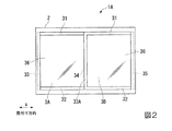
図1および図2に示すように、第1実施形態によるサッシ1Aは、引違窓のアルミニウムと樹脂の複合のサッシで、建物11の開口部12に固定されたサッシ枠2と、サッシ枠2の内部に見付け方向(図中の矢印Aの方向)にスライド可能に設置される室外側サッシ障子3Aおよび室内側サッシ障子3Bと、を備えている。
(First embodiment)
Hereinafter, a sash according to a first embodiment of the present invention will be described with reference to FIGS. 1 to 3.
As shown in FIG. 1 and FIG. 2, the
室外側サッシ障子3Aおよび室内側サッシ障子3Bは、見付け方向に延在する上框31,31および下框32,32(図2参照)と、上下方向に延在する召合框33A,34および戸先框35,35と、これらの框の内側に配置されるガラス36,36と、をそれぞれ有している。
ここで、見付け方向のうち、室外側サッシ障子3Aおよび室内側サッシ障子3Bが開口部12を閉鎖した際に室外側サッシ障子3Aが配置される側を左側(図1乃至図3の左側)とし、室内側サッシ障子3Bが配置される側を右側(図1乃至図3の右側)として以下説明する。
また、室内側サッシ障子3Bの召合框(召合内框)33A以外は、公知のものとして以下説明する。
The
Here, in the direction of finding, the side on which the outdoor
Moreover, it explains below as a well-known thing except 33A of summoning jars (summoning niece) 33A of the
図3に示すように、召合内框33Aは、室外13側に位置する室外側形材4Aと、室内14側に位置する室内側形材5Aと、室外側形材4Aと室内側形材5Aとの間に設けられた第1断熱ブリッジ材6A(6)および第2断熱ブリッジ材6B(6)と、室内側形材5Aの室内14と対向する面を覆う樹脂カバー材7と、を有している。
As shown in FIG. 3, the
室外側形材4Aは、召合内框33Aの略全高さにわたって鉛直方向に延在する形材で、水平断面が中空の略長方形状の基部41Aと、煙返し部42を構成する第1見付け片43および第2見付け片44と、第1断熱ブリッジ材6Aと係合する一対の第1係合片45,45と、第2断熱ブリッジ材6Bと係合する一対の第2係合片46,46と、を有している。これらの部材はアルミニウムを材料として押出成形によって一体に形成されている。
The
基部41Aは、断面形状が略角筒状となるように構成され、側面がそれぞれ見付け方向および見込み方向(図中の矢印Bの方向、図2においては紙面に直交する方向)を向くように配置されている。
第1見付け片43は、平板状に形成され、室外13側の面が基部41Aの室外13側の側面と略面一となるように基部41Aから右側に向かって突設されている。
第2見付け片44は、平板状に形成され、基部41Aの右側の側面の見込み方向の中間部に突設されている。第1見付け片43と第2見付け片44との間には、見込み方向に所定の間隔があけられていて、この間には、室外側サッシ障子3Aの召合框(召合外框)34の煙返し部の見付け片81が挿入可能に構成されている。
41 A of base parts are comprised so that cross-sectional shape may become a substantially rectangular tube shape, and it arrange | positions so that a side surface may face a direction of finding and a prospective direction (the direction of the arrow B in a figure, the direction orthogonal to a paper surface in FIG. 2), respectively. Has been.
The
The
一対の第1係合片45,45は、見込み方向に間隔をあけて配置されていて、基部41Aの左側の面からそれぞれ略左側に突出する見付け片45a,45aと、見付け片45a,45aの先端部からそれぞれ向かい合う見付け片45a側に突出する爪部45b,45bと、を有している。
そして、一対の第1係合片45,45は、これらの間に第1断熱ブリッジ材6Aが配置されていて、一対の爪部45b,45bが第1断熱ブリッジ材6Aに食い込み、一対の見付け片45a,45aが第1断熱ブリッジ材6Aの側面を押さえ、第1断熱ブリッジ材6Aをかしめて挟持するように構成されている。
The pair of
The pair of
一対の第2係合片46,46は、見付け方向に間隔をあけて配置されていて、基部41Aの室内14側の面からそれぞれ室内14側に突出する見込み片46a,46aと、見込み片46a,46aの先端部からそれぞれ対向する見込み片46a側に突出する爪部46b,46bと、を有している。
そして、一対の第2係合片46,46は、これらの間に第2断熱ブリッジ材6Bが配置されていて、一対の爪部46b,46bが第2断熱ブリッジ材6Bに食い込み、一対の見込み片46a,46aが第2断熱ブリッジ材6Bの側面を押さえ、第2断熱ブリッジ材6Bをかしめて挟持するように構成されている。
The pair of
The pair of
室内側形材5Aは、召合内框33Aの略全高さにわたって鉛直方向に延在する形材で、水平断面が中空の略長方形状の基部51Aと、第1断熱ブリッジ材6Aと係合する一対の第1係合片52,52と、基部51Aと一対の第1係合片52,52とを連結する連結片53と、第2断熱ブリッジ材6Bと係合する一対の第2係合片54,54と、を有している。これらの部材は室外側形材4Aと同様のアルミニウムを材料として押出成形によって一体に形成されている。
室内側形材5Aは、室外側形材4Aよりも大きな断面形状に形成されている。また、室内側形材5Aを形成する材料(本実施形態ではアルミニウム)の質量および体積は、室外側形材4Aを形成する材料の質量および体積よりも大きくなるように構成されている。
The indoor-
The
基部51Aは、断面形状が略角筒状となるように構成され、側面がそれぞれ見付け方向および見込み方向を向くように配置されている。
また、基部51Aは、室内14側の面に、断面形状が略L字状で樹脂カバー材7を係止可能な第1樹脂カバー係止片55が突設されている。第1樹脂カバー係止片55は、基部51Aの室内14側の面から室内14側に突出する見込み片55aと、この見込み片55aの室内14側の端部から右側に向かって突出する見付け片55bと、を有している。そして、基部51Aと見付け片55bとの間には空部55cが形成されている。
51 A of base parts are comprised so that cross-sectional shape may become a substantially rectangular tube shape, and it is arrange | positioned so that a side surface may face a finding direction and a prospective direction, respectively.
Further, the
連結片53は、左側の面が基部51Aの左側の面と面一と略面一となるように基部51Aから室外13側に向かって突設された板状の第1見込み片53aと、第1見込み片53aと連続し第1見込み片53aの室外13側の端部から右側に向かって突出する板状の見付け片53bと、見付け片53bと連続し見付け片53bの右側の端部から室外13側に向かって突出する板状の第2見込み片53cと、を有している。
第1見込み片53aと見付け片53bとの連続部分は角部を構成していて、この角部には室外13側に突出する板状で樹脂カバー材7を係止可能な第2樹脂カバー係止片56が設けられている。
第2見込み片53cに、右側の面に一対の第1係合片52,52が突設されている。
The connecting
A continuous portion of the first
A pair of
一対の第1係合片52,52は、見込み方向に間隔をあけて配置されていて、連結片53の第2見込み片53cの右側の面からそれぞれ略右側に突出する見付け片52a,52aと、見付け片52a,52aの先端部からそれぞれ向かい合う第1係合片52側に突出する爪部52b,52bと、を有している。
そして、一対の第1係合片52,52は、これらの間に第1断熱ブリッジ材6Aが配置されていて、一対の爪部52b,52bが第1断熱ブリッジ材6Aに食い込み、一対の見付け片52a,52aが第1断熱ブリッジ材6Aの室外13側および室内14側の側面を押さえ、第1断熱ブリッジ材6Aをかしめて挟持するように構成されている。
なお、室外側形材4Aの一対の第1係合片45,45と、室内側形材5Aの一対の第1係合片52,52とは、離間していて、第1断熱ブリッジ材6Aを介して見込み方向に対向するように配置されている。
The pair of
The pair of
It should be noted that the pair of first engaging
一対の第2係合片54,54は、見付け方向に間隔をあけて配置されていて、基部51Aの室外13側の面からそれぞれ室外13側に突出する見込み片54a,54aと、見込み片54a,54aの先端部からそれぞれ向かい合う第2係合片54側に突出する爪部54b,54bと、を有している。
そして、一対の第2係合片54,54は、これらの間に第2断熱ブリッジ材6Bが配置されていて、一対の爪部54b,54bが第2断熱ブリッジ材6Bに食い込み、一対の見込み片54a,54aが第2断熱ブリッジ材6Bの左側および右側の側面を押さえ、第2断熱ブリッジ材6Bをかしめて挟持するように構成されている。
なお、室外側形材4Aの一対の第2係合片46,46と、室内側形材5Aの一対の第2係合片54,54とは、離間していて、第2断熱ブリッジ材6Bを介して見付け方向に対向するように配置されている。
The pair of
The pair of second
The pair of second
第1断熱ブリッジ材6Aおよび第2断熱ブリッジ材6Bは、それぞれ召合内框33Aのの略全高さにわたって鉛直方向に延在する部材で、室外側形材4Aおよび室内側形材5Aを形成する材料よりも熱伝導率の低い樹脂やウレタンを材料として形成されている。
第1断熱ブリッジ材6Aは、右側の端部近傍が室外側形材4Aの第1係合片45,45と係合し、左側の端部近傍が室内側形材5Aの第1係合片52,52と係合している。また、第2断熱ブリッジ材6Bは、室外13側の端部近傍が室外側形材4Aの第2係合片46,46と係合し、左側の端部近傍が室内側形材5Aの第2係合片54,54と係合している。
そして、第1断熱ブリッジ材6Aおよび第2断熱ブリッジ材6Bは、室外側形材4Aと室内側形材5Aとを連結し、室外側形材4A、室内側形材5A、第1断熱ブリッジ材6Aおよび第2断熱ブリッジ材6Bは一体化されている。
なお、室外側形材4A、室内側形材5A、第1断熱ブリッジ材6Aおよび第2断熱ブリッジ材6Bが一体化すると、室外側形材4Aの第1見付け片43および第2見付け片44が、室内側形材5Aの基部51Aの右側の面よりも右側に位置している。
The first heat insulating
In the first heat insulating
And the 1st heat insulation bridge | bridging
When the
樹脂カバー材7は、召合内框33Aの略全高さにわたって鉛直方向に延在する部材で、室外側形材4Aおよび室内側形材5Aを形成する材料よりも熱伝導率の低い樹脂を材料として形成されている。樹脂カバー材7は、室内側形材5Aの室内14側に配置されて断面形状が中空で略長方形状の筒部71と、室内側形材5Aの左側に配置されて筒部71と連続する板状の板部72と、を有している。
筒部71は、側面がそれぞれ見付け方向および見込み方向を向くように配置されている。また、板部72は、板面が見付け方向を向くように配置されている。そして、筒部71と板部72とは、それぞれの左側の面が面一となるように一体に形成されている。
The
The
筒部71には、室外13側の面に断面形状が略L字状に形成され、室内側形材5Aの第1樹脂カバー係止片55に係止される第1被係止部73が突設されている。第1被係止部73は、筒部71の室外13側の面から室外13側に突出する見込み片73aと、この見込み片73aの室外13側の端部から左側に突出する見付け片73bと、を有している。筒部71と見付け片73bの間には、空部73cが形成されている。
また、筒部71には、室外13側の面に室内側形材5A(室外13側)に向かって突出する突出片74が設けられている。
The
Further, the
板部72には、右側の面の室外13側の端部に、板状に形成されて室内側形材5Aの第2樹脂カバー係止片56に係止される第2被係止片75が突設されている。第2被係止片75は、板部72から右側に延びる見付け片75aと、見付け片75aの先端部から室内14側に向かって突出する爪部75bと、を有している。
The
また、第2被係止片75の見付け片75aは、室外13側の面が、室外側サッシ障子3Aの召合外框34の樹脂カバー材34aと対向している。ここで、召合外框34について説明すると、召合外框34は、室外13側に位置しアルミニウムを材料として形成された形材34bと、室内14側に位置する樹脂カバー材34aと、を有している。なお、上述した室外側サッシ障子3Aの煙返し部の見付け片81は、形材34bに連結されている。
そして、第2被係止片75の見付け片75aには、室外13側の面から室外13側に突出し、先端部が召合外框34の樹脂カバー材34aと当接またはわずかな隙間をあけて離間する突起部75cが、召合内框33Aの略全高さにわたって設けられている。
このような突起部75cは、その室外13側(召合外框34側)と室内14側とを区分して、室外13側と室内14側とを断熱している。
In addition, the
Then, the
Such a
また、板部72には、右側の面に室内側形材5A(右側)に向かって突出する複数の突出片76,76…が設けられている。
そして、筒部71の第1被係止部73の見付け片73bが、室内側形材5Aの基部51Aと第1樹脂カバー係止片55の見付け片55bとの間の空部55cに嵌合し、第1樹脂カバー係止片55の見付け片55bが、筒部71と第1被係止部73の見付け片73bとの間の空部73cに嵌合するとともに、板部72の第2被係止片75の爪部75bが第2樹脂カバー係止片56に係止されると、樹脂カバー材7が室内側形材5Aに係止されるように構成されている。
このとき、筒部71の突出片74の先端部が室内側形材5Aの室内13側の面と当接し、板部72の突出片76,76…の先端部が室内側形材5Aの左側の面と当接している。
Further, the
And the
At this time, the distal end portion of the projecting
また、筒部71は、見付け方向の寸法が室内側形材5Aの見付け方向の寸法よりも大きく形成され、右側の面が室内側形材5Aの基部51Aの右側の面よりも右側に位置している。
これにより、室内側形材5Aの基部51Aの右側には、室外側形材4Aの煙返し部42の第2見付け片44と樹脂カバー材7の筒部71の右側の端部近傍の部分とに挟まれた溝状の空間82が形成されている。そして、この空間82には、室内側サッシ障子3Bのガラス36が嵌合するように構成されている。
Moreover, the
Thereby, on the right side of the
次に、上述した第1実施形態によるサッシ1Aの作用・効果について図面を用いて説明する。
第1実施形態によるサッシ1Aによれば、室外側形材4Aの断面形状が、室内側形材5Aの断面形状よりも小さいことにより、室内外の温度差によって室外側形材4Aが膨張し、室内側形材5Aが収縮する際に、室外側形材4Aが膨張する力の方が、室内側形材5Aが収縮する力よりも大きくなるため、室外側形材4Aの膨張に室内側形材5Aを追従させることができる。これにより、室外側形材4Aが反ることを防止できる。
Next, operations and effects of the
According to the
また、室外側形材4Aの断面形状が、室内側形材5Aの断面形状よりも小さいことにより、室外側形材4Aの断面形状と室内側形材5Aの断面形状とが同じ場合や、室外側形材4Aの断面形状が室内側形材5Aの断面形状よりも大きい場合と比べて、室外13の冷温が、室外側形材4Aを介して室内側形材5Aへ伝わりにくい構造となるため、召合内框33Aにおいて効率よく室内外を断熱できるとともに、室内14の結露を防止できる。
Moreover, when the cross-sectional shape of the outdoor-
また、室外側形材4Aは、煙返し部42であることにより、煙返し部42である室外側形材4Aの断面形状と、煙返し部42以外となる室内側形材5Aの断面形状との大きさの差を大きくできるため、室内外の温度差が大きく室内側形材5Aが膨張した際に、この膨張に室外側形材4Aをより追従させることができ、室内側形材5Aが反ることを防止できる。
Further, since the
第1断熱ブリッジ材6Aおよび第2断熱ブリッジ材6Bは、室外側形材4Aと室内側形材5Aとの間に2つ設けられていることにより、室外側形材4Aと室内側形材5Aとの連結部分となるため、室外側形材4Aと室内側形材5Aとを確実に連結できる。
The first heat
(第2実施形態)
次に、第2実施形態について、添付図面に基づいて説明するが、上述の第1実施形態と同一又は同様な部材、部分には同一の符号を用いて説明を省略し、第1実施形態と異なる構成について説明する。
図4に示すように、第2実施形態によるサッシ1Bは、召合内框33Bの室外側形材4Bおよび室内側形材5Bの水平断面形状が、図3に示す第1実施形態による召合内框33Aの室外側形材4Aおよび室内側形材5Aと異なり、室外側形材4Bと室内側形材5Bとが見付け方向に対して斜めに対向し、対向する室外側形材4Bと室内側形材5Bとの間に1つの第3断熱ブリッジ材6C(6)が設けられている。
室外側形材4Bは、室内側形材5Bに対して右側かつ室外13側の斜めの位置に配置されている。なお、召合内框33Bの各部材を形成する材料や、樹脂カバー材7、室内側形材5Bが樹脂カバー材7を係止する形態については第1実施形態と同様のものとして以下説明する。
(Second Embodiment)
Next, the second embodiment will be described with reference to the accompanying drawings. However, the same or similar members and parts as those in the first embodiment are denoted by the same reference numerals, and the description thereof is omitted. A different configuration will be described.
As shown in FIG. 4, in the
The
室外側形材4Bは、水平断面が中実であるとともに室内側形材5Bと対向する側に左側から右側に向かって漸次室外13側から室外13側に向かう斜めの面4aが形成された基部41Bと、基部41Bに突設され第1実施形態と同様に煙返し部42を構成する第1見付け片43および第2見付け片44と、を有している。
基部41Bには、室内側形材5Bと対向する側に断面形状が略C字状の溝部47が形成されて、この溝部47の内部に第3断熱ブリッジ材6Cが嵌合するように構成されている。溝部47の両側部48,48には、他方の側部48側に突出する爪部48a,48aが形成されていて、溝部47の両側部48,48が第3断熱ブリッジ材6Cをかしめて挟持するように構成されている。
The
A groove portion 47 having a substantially C-shaped cross section is formed in the
室内側形材5Bは、水平断面が中空の部材で、室外側形材4Bと対向する側に左側から右側に向かって漸次室外13側から室内14側に向かう斜めの面5aが形成された基部51Bを有している。
基部51Bには、室外側形材4Bと対向する側に断面形状が略C字状の溝部57が形成されて、この溝部57の内部に第3断熱ブリッジ材6Cが嵌合するように構成されている。溝部57の両側部58,58には、他方の側部58側に突出する爪部58a,58aが形成されていて、溝部57の両側部58,58が第3断熱ブリッジ材6Cをかしめて挟持するように構成されている。
The indoor
A
第2実施形態においても、第1実施形態と同様に、室内側形材5Bは、室外側形材4Bよりも大きな断面形状に形成されている。また、室内側形材5Bを形成する材料(本実施形態ではアルミニウム)の質量および体積は、室外側形材4Bを形成する材料の質量および体積よりも大きくなるように構成されている。
また、第3断熱ブリッジ材6Cは、第1実施形態による第1断熱ブリッジ材6Aおよび第2断熱ブリッジ材6Bと同様に、室外側形材4Bと室内側形材5Bとを連結し、室外側形材4B、室内側形材5B、第3断熱ブリッジ材6Cは一体化している。
Also in the second embodiment, as in the first embodiment, the indoor-
The third heat insulating
また、第2実施形態では、樹脂カバー材7の板部72の室外13側の端部に、第1実施形態による第2被係止片75に設けられた突起部75c(図3参照)と同様の突起部75dが設けられている。この突起部75dも、先端部が召合外框34の樹脂カバー材34aと当接またはわずかな隙間をあけて離間しており、その室外13側(召合外框34側)と室内14側とを区分して、室外13側と室内14側とを断熱している。
Moreover, in 2nd Embodiment, the
第2実施形態によるサッシ1Bによれば、第1実施形態と同様の効果を奏するとともに、第3断熱ブリッジ材6Cを、見込み方向に対して斜めに対向する室外側形材4Bと室内側形材5Bとの間に設けることができるため、室外側形材4Bの断面形状の大きさと室内側形材5Bの断面形状の大きさとの差が大きく、また、室外側形材4Bと室内側形材5Bとが見込み方向に対向する部分が小さい場合も、室外側形材4Bおよび室内側形材5Bに見込み方向に対して斜めに対向する部分があれば第3断熱ブリッジ材6Cを設けることができる。
According to the
また、室外側形材4Bと室内側形材5Bとの間の断熱ブリッジ材が、1つの第3断熱ブリッジ材6Cであることにより、室外側形材4Bと室内側形材5Bとの間に複数の断熱ブリッジ材が設けられている場合と比べて、室外側形材4Bから室内側形材5Bへ室外13の冷温が伝わりにくい構造とすることができる。
Moreover, since the heat insulation bridge material between the outdoor
以上、本発明によるサッシの実施形態について説明したが、本発明は上記の実施形態に限定されるものではなく、その趣旨を逸脱しない範囲で適宜変更可能である。
例えば、上記の実施形態では、サッシ1A,1Bは、引違窓のサッシとしているが、上げ下げ窓のサッシとしてもよい。なお、上げ下げ窓の場合、サッシ1A,1Bの各部材が、本実施形態の上下方向が見付け方向となり、見付け方向が上下方向となるように配置されていればよい。
また、上記の実施形態では、サッシ1A,1Bは、アルミニウムと樹脂の複合サッシであるが、複合サッシ以外の例えばアルミニウムなどの金属製のサッシなどでもよい。金属製のサッシの場合は、樹脂カバー材7が設けられていない構成としてもよい。
また、室外側形材4A,4Bおよび室内側形材5A,5Bは、アルミニウム以外の金属などを材料として形成されていてもよい。
As mentioned above, although embodiment of the sash by this invention was described, this invention is not limited to said embodiment, In the range which does not deviate from the meaning, it can change suitably.
For example, in the above-described embodiment, the
In the above embodiment, the
Further, the
また、上記の実施形態では、室外側形材4A,4Bは、煙返し部42であるが、室外側形材4A,4Bの断面形状が室内側形材5A,5Bの断面形状よりも小さければ、煙返し部42B以外の部材が含まれていてもよい。
Moreover, in said embodiment, although
また、上記の第1実施形態では、断熱ブリッジ材6が2つ設けられ、第2実施形態では、断熱ブリッジ材6が1つ設けられているが、断熱ブリッジ材6が設けられる数は1つ以上であれば適宜設定されてよい。
In the first embodiment, two heat insulating
また、上記の実施形態では、室外側形材4A,4Bおよび室内側形材5A,5Bは、それぞれ断熱ブリッジ材6をかしめて挟持し、これにより室外側形材4A,4Bおよび室内側形材5A,5Bと断熱ブリッジ材6とが係合しているが、室外側形材4A,4Bおよび室内側形材5A,5Bと断熱ブリッジ材6との係合の形態は適宜設定されてよい。
また、召合内框33A,33Bは、室外側形材4A,4Bと室内側形材5A,5Bとの間に断熱ブリッジ材6が設けられていて、室外側形材4A,4Bの断面形状が室内側形材5A,5Bの断面形状よりも小さければ、上記以外の構成であってもよい。
Further, in the above embodiment, the
In addition, in the
1A,1B サッシ
3A 室外側サッシ障子
3B 室内側サッシ障子
4A,4B 室外側形材
5A,5B 室内側形材
6,6A 第1断熱ブリッジ材(断熱ブリッジ材)
6,6B 第2断熱ブリッジ材(断熱ブリッジ材)
6,6C 第3断熱ブリッジ材(断熱ブリッジ材)
7 樹脂カバー材
13 室外
14 室内
33A,33B 召合内框
42 煙返し部
1A,
6,6B Second heat insulation bridge material (heat insulation bridge material)
6,6C 3rd heat insulation bridge material (heat insulation bridge material)
7 Resin cover material 13 Outdoor 14 Indoor 33A, 33B Summit
Claims (5)
前記室外側形材の断面形状が、前記室内側形材の断面形状よりも小さいことを特徴とするサッシ。 An outdoor shape located on the outdoor side, an indoor shape located on the indoor side, and the outdoor shape and the indoor shape provided between the outdoor shape and the indoor shape. An insulative bridging member having a heat-insulating bridge material connecting the materials,
A sash, wherein a cross-sectional shape of the outdoor-side shape member is smaller than a cross-sectional shape of the indoor-side shape member.
Priority Applications (1)
| Application Number | Priority Date | Filing Date | Title |
|---|---|---|---|
| JP2014073386A JP6283246B2 (en) | 2014-03-31 | 2014-03-31 | sash |
Applications Claiming Priority (1)
| Application Number | Priority Date | Filing Date | Title |
|---|---|---|---|
| JP2014073386A JP6283246B2 (en) | 2014-03-31 | 2014-03-31 | sash |
Publications (2)
| Publication Number | Publication Date |
|---|---|
| JP2015194056A true JP2015194056A (en) | 2015-11-05 |
| JP6283246B2 JP6283246B2 (en) | 2018-02-21 |
Family
ID=54433309
Family Applications (1)
| Application Number | Title | Priority Date | Filing Date |
|---|---|---|---|
| JP2014073386A Active JP6283246B2 (en) | 2014-03-31 | 2014-03-31 | sash |
Country Status (1)
| Country | Link |
|---|---|
| JP (1) | JP6283246B2 (en) |
Cited By (4)
| Publication number | Priority date | Publication date | Assignee | Title |
|---|---|---|---|---|
| JP2017180052A (en) * | 2016-03-31 | 2017-10-05 | 株式会社Lixil | Airtight / insulated structure of sash window |
| JP2020197118A (en) * | 2020-09-01 | 2020-12-10 | 株式会社Lixil | Sash-window airtight/thermal insulation structure |
| JP2021032045A (en) * | 2019-08-29 | 2021-03-01 | 株式会社Lixil | Sash and fixture |
| JP2022066464A (en) * | 2018-02-20 | 2022-04-28 | 株式会社Lixil | Fitting |
Citations (5)
| Publication number | Priority date | Publication date | Assignee | Title |
|---|---|---|---|---|
| US4554770A (en) * | 1984-01-11 | 1985-11-26 | National Gypsum Company | Horizontal sliding window with removable fixed sash |
| JPH0868268A (en) * | 1994-08-31 | 1996-03-12 | Ykk Architect Prod Kk | Insulated window |
| JPH10196226A (en) * | 1997-01-08 | 1998-07-28 | Fujisash Co | Insulation sash underframe |
| JP2002004729A (en) * | 1996-04-24 | 2002-01-09 | Ykk Architectural Products Inc | Construction method of sash window |
| JP2002161671A (en) * | 2000-11-27 | 2002-06-04 | Ykk Architectural Products Inc | Sash window |
-
2014
- 2014-03-31 JP JP2014073386A patent/JP6283246B2/en active Active
Patent Citations (5)
| Publication number | Priority date | Publication date | Assignee | Title |
|---|---|---|---|---|
| US4554770A (en) * | 1984-01-11 | 1985-11-26 | National Gypsum Company | Horizontal sliding window with removable fixed sash |
| JPH0868268A (en) * | 1994-08-31 | 1996-03-12 | Ykk Architect Prod Kk | Insulated window |
| JP2002004729A (en) * | 1996-04-24 | 2002-01-09 | Ykk Architectural Products Inc | Construction method of sash window |
| JPH10196226A (en) * | 1997-01-08 | 1998-07-28 | Fujisash Co | Insulation sash underframe |
| JP2002161671A (en) * | 2000-11-27 | 2002-06-04 | Ykk Architectural Products Inc | Sash window |
Cited By (13)
| Publication number | Priority date | Publication date | Assignee | Title |
|---|---|---|---|---|
| JP2017180052A (en) * | 2016-03-31 | 2017-10-05 | 株式会社Lixil | Airtight / insulated structure of sash window |
| JP7901653B2 (en) | 2018-02-20 | 2026-08-06 | 株式会社Lixil | Doors and fittings |
| JP2022066464A (en) * | 2018-02-20 | 2022-04-28 | 株式会社Lixil | Fitting |
| JP2022071163A (en) * | 2018-02-20 | 2022-05-13 | 株式会社Lixil | Joinery |
| JP2025015787A (en) * | 2018-02-20 | 2025-01-30 | 株式会社Lixil | Fitting |
| JP7316881B2 (en) | 2019-08-29 | 2023-07-28 | 株式会社Lixil | Shoji and fittings |
| JP2021032045A (en) * | 2019-08-29 | 2021-03-01 | 株式会社Lixil | Sash and fixture |
| JP7134203B2 (en) | 2020-09-01 | 2022-09-09 | 株式会社Lixil | Airtight/insulating structure of sash window |
| JP2023060233A (en) * | 2020-09-01 | 2023-04-27 | 株式会社Lixil | Airtight/insulating structure of sash windows |
| JP7337234B2 (en) | 2020-09-01 | 2023-09-01 | 株式会社Lixil | sash window |
| JP2022125214A (en) * | 2020-09-01 | 2022-08-26 | 株式会社Lixil | Airtight/insulating structure of sash window |
| JP7642004B2 (en) | 2020-09-01 | 2025-03-07 | 株式会社Lixil | Airtight/insulating structure of sash window and sash window |
| JP2020197118A (en) * | 2020-09-01 | 2020-12-10 | 株式会社Lixil | Sash-window airtight/thermal insulation structure |
Also Published As
| Publication number | Publication date |
|---|---|
| JP6283246B2 (en) | 2018-02-21 |
Similar Documents
| Publication | Publication Date | Title |
|---|---|---|
| JP6283246B2 (en) | sash | |
| JP6091924B2 (en) | Opening device | |
| KR101569647B1 (en) | Insulation for fittings frame members | |
| JP6357060B2 (en) | Joinery | |
| JP5982199B2 (en) | Joinery | |
| KR102349022B1 (en) | Fire protection door and its manufacturing method | |
| KR20200001540U (en) | project windows system | |
| JP6502051B2 (en) | Heat insulation sash | |
| JP2017057709A (en) | Fixture | |
| KR101515800B1 (en) | System Window | |
| JP6466649B2 (en) | Sash structure | |
| KR101975558B1 (en) | Fire door for preventing dew condensation | |
| JP6333767B2 (en) | Joinery | |
| JP6259344B2 (en) | Composite fixture fixing members and composite fixtures | |
| KR101623939B1 (en) | Curtain wall window having improved heat isolation | |
| KR20170038436A (en) | A curtain wall frame | |
| JP2020063607A (en) | curtain wall | |
| KR101743980B1 (en) | Outside insulation panel unit and its construction method | |
| JP6124017B2 (en) | Sash upper frame | |
| JP6280891B2 (en) | Joinery | |
| JP6804212B2 (en) | Airtight / insulated structure of sash window | |
| KR101171468B1 (en) | Doorframe for Dewdrops Prevention | |
| JP2016098572A (en) | Fixture | |
| KR101595219B1 (en) | Insulating frame for windows and doors with improved Insulation property and solidity | |
| JP6758883B2 (en) | Airtight / insulated structure of sash window |
Legal Events
| Date | Code | Title | Description |
|---|---|---|---|
| A621 | Written request for application examination |
Free format text: JAPANESE INTERMEDIATE CODE: A621 Effective date: 20160721 |
|
| A977 | Report on retrieval |
Free format text: JAPANESE INTERMEDIATE CODE: A971007 Effective date: 20170608 |
|
| A131 | Notification of reasons for refusal |
Free format text: JAPANESE INTERMEDIATE CODE: A131 Effective date: 20170613 |
|
| A521 | Request for written amendment filed |
Free format text: JAPANESE INTERMEDIATE CODE: A523 Effective date: 20170809 |
|
| TRDD | Decision of grant or rejection written | ||
| A01 | Written decision to grant a patent or to grant a registration (utility model) |
Free format text: JAPANESE INTERMEDIATE CODE: A01 Effective date: 20180123 |
|
| A61 | First payment of annual fees (during grant procedure) |
Free format text: JAPANESE INTERMEDIATE CODE: A61 Effective date: 20180126 |
|
| R150 | Certificate of patent or registration of utility model |
Ref document number: 6283246 Country of ref document: JP Free format text: JAPANESE INTERMEDIATE CODE: R150 |
|
| S111 | Request for change of ownership or part of ownership |
Free format text: JAPANESE INTERMEDIATE CODE: R313111 |
|
| R350 | Written notification of registration of transfer |
Free format text: JAPANESE INTERMEDIATE CODE: R350 |