JP2015158103A - sanitary washing device - Google Patents
sanitary washing device Download PDFInfo
- Publication number
- JP2015158103A JP2015158103A JP2014033757A JP2014033757A JP2015158103A JP 2015158103 A JP2015158103 A JP 2015158103A JP 2014033757 A JP2014033757 A JP 2014033757A JP 2014033757 A JP2014033757 A JP 2014033757A JP 2015158103 A JP2015158103 A JP 2015158103A
- Authority
- JP
- Japan
- Prior art keywords
- air
- shutter
- heater
- drying
- sanitary washing
- Prior art date
- Legal status (The legal status is an assumption and is not a legal conclusion. Google has not performed a legal analysis and makes no representation as to the accuracy of the status listed.)
- Pending
Links
Images


Abstract
Description
本発明は乾燥装置と静電霧化装置を備えた衛生洗浄装置に関するものである。 The present invention relates to a sanitary washing device including a drying device and an electrostatic atomizer.
従来、この種の使用者の局部を乾燥する帯電微粒子水と、除菌および脱臭等の機能を有する帯電微粒子水を生成する静電霧化装置を備えた衛生洗浄装置は、それぞれ独立した乾燥装置と静電霧化装置を個別に設置した構成となっている。乾燥装置は衛生洗浄装置の本体の略中央部に配置されており、便器の中央部に向かって温風を噴出し、使用者の局部を乾燥する。一方、静電霧化装置は本体の側部より突出するように配置されており、トイレルーム内に帯電微粒子を噴出する構成となっている(例えば、特許文献1参照)。 Conventionally, a sanitary washing device provided with an electrostatic atomizer for generating charged fine particle water for drying a local part of this type of user and a charged fine particle water having functions such as sterilization and deodorization is an independent drying device. And the electrostatic atomizer is installed separately. The drying device is arranged at a substantially central portion of the main body of the sanitary washing device, and blows warm air toward the central portion of the toilet to dry the user's local area. On the other hand, the electrostatic atomizer is disposed so as to protrude from the side of the main body, and is configured to eject charged fine particles into the toilet room (see, for example, Patent Document 1).
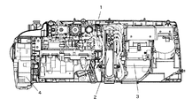
図8は、特許文献1に記載された従来の衛生洗浄装置の内部を示すものである。図8に示すように、衛生洗浄装置の本体1の中央部に使用者の局部を洗浄するノズル装置2が設置してあり、ノズル装置2の側方に乾燥装置3が設置してある。また、本体1の側部に突出して静電霧化装置4が設置されている。
FIG. 8 shows the inside of a conventional sanitary washing apparatus described in
しかしながら、前記従来の構成では、乾燥装置と静電霧化装置の必須機能である送風装置をそれぞれが独立して備えた構成となっている。そのため、2つの送風装置を設置するための広いスペースが必要となり、衛生洗浄装置全体が大型となるため設置条件等の使い勝手の観点で改良の余地があった。また、2個の送風装置を使用するため、材料コストと生産性の面でも改良の余地があった。 However, in the said conventional structure, it is the structure which each equipped independently with the air blower which is an essential function of a drying apparatus and an electrostatic atomizer. Therefore, a large space for installing the two blowers is required, and the entire sanitary washing device becomes large, so there is room for improvement in terms of ease of use such as installation conditions. Further, since two air blowers are used, there is room for improvement in terms of material cost and productivity.
本発明は、前記従来の課題を解決するもので、乾燥装置と静電霧化装置を一体化し、1個の送風装置を共用することで、設置スペースを縮小するとともに、コストと組立工数を削減することにより、使い勝手の良い衛生洗浄装置を低コストで提供することを目的とする。 The present invention solves the above-described conventional problems, and integrates a drying device and an electrostatic atomizer to share one blower, thereby reducing installation space and reducing costs and assembly steps. Therefore, an object is to provide a user-friendly sanitary washing device at a low cost.
前記従来の課題を解決するために、本発明の衛生洗浄装置は、便器上に載置される本体と、本体に起倒自在に枢支された便座と、人体局部を洗浄する洗浄手段と、人体局部を乾燥する乾燥装置と、乾燥装置の駆動に伴い開閉されるシャッターと、少なくとも洗浄手段と乾燥装置を制御する制御部と、を含み、乾燥装置は、風路を形成するケースと、空気を送給する送風装置と、空気を加熱するヒータと、帯電微粒子水を生成する静電霧化装置と、を備え、制御部は、ヒータの駆動時と静電霧化装置の駆動時とでは、シャッターの開度が異なるように制御することを特徴とするものである。 In order to solve the above-described conventional problems, the sanitary washing device of the present invention includes a main body placed on a toilet bowl, a toilet seat pivotally supported by the main body, and a washing means for washing a human body part, A drying device that dries the human body part; a shutter that is opened and closed as the drying device is driven; and a control unit that controls at least the cleaning means and the drying device. The drying device includes a case that forms an air passage, and an air A blower that feeds air, a heater that heats air, and an electrostatic atomizer that generates charged fine particle water, and the controller is configured to drive the heater and the electrostatic atomizer at the time of driving. The control is performed so that the opening degree of the shutter is different.
これにより、乾燥装置はヒータにより加熱された温風と、静電霧化装置で生成された帯電微粒子水が付加された空気をそれぞれ生成して噴出することができ、1個の送風装置を2つの機能で共用するとともに、ヒータの駆動時と前記静電霧化装置の駆動時とでシャッターの開度を変更することにより、性状の異なる空気をそれぞれ目的に合った風量および方向に噴出させることができるとともに、設置スペースの縮小と、材料コストと組立工数
を削減することができる。
As a result, the drying device can generate and eject hot air heated by the heater and air to which the charged fine particle water generated by the electrostatic atomizer is added, so that one blower can be In addition to being shared by two functions, by changing the opening of the shutter between when the heater is driven and when the electrostatic atomizer is driven, air having different properties can be ejected in the air volume and direction suitable for each purpose. In addition, the installation space can be reduced, and the material cost and the number of assembly steps can be reduced.
本発明の衛生洗浄装置は、小型で使い勝手の良い衛生洗浄装置を低コストで提供することができる。 The sanitary washing device of the present invention can provide a sanitary washing device that is small and easy to use at low cost.
第1の発明は、便器上に載置される本体と、前記本体に起倒自在に枢支された便座と、人体局部を洗浄する洗浄手段と、人体局部を乾燥する乾燥装置と、前記乾燥装置の駆動に伴い開閉されるシャッターと、少なくとも前記洗浄手段と乾燥装置を制御する制御部と、を含み、前記乾燥装置は、風路を形成するケースと、空気を送給する送風装置と、空気を加熱するヒータと、帯電微粒子水を生成する静電霧化装置と、を備え、前記制御部は、前記ヒータの駆動時と前記静電霧化装置の駆動時とでは、前記シャッターの開度が異なるように制御することを特徴とする衛生洗浄装置。 According to a first aspect of the present invention, there is provided a main body placed on a toilet bowl, a toilet seat pivotally supported by the main body, a cleaning means for cleaning the human body part, a drying device for drying the human body part, and the drying A shutter that is opened and closed as the apparatus is driven, and a controller that controls at least the cleaning unit and the drying apparatus, the drying apparatus including a case that forms an air passage, and a blower that feeds air. A heater that heats air, and an electrostatic atomizer that generates charged fine particle water, and the controller opens the shutter when the heater is driven and when the electrostatic atomizer is driven. A sanitary washing device that is controlled to have different degrees.
これにより、乾燥装置はヒータにより加熱された温風と、静電霧化装置で生成された帯電微粒子水が付加された空気をそれぞれ生成して噴出することができ、1個の送風装置を2つの機能で共用するとともに、ヒータの駆動時と静電霧化装置の駆動時とでシャッターの開度を変更することにより、性状の異なる空気をそれぞれ目的に合った風量および方向に噴出させることができるとともに、設置スペースの縮小と、材料コストと組立工数を削減することができる。 As a result, the drying device can generate and eject hot air heated by the heater and air to which the charged fine particle water generated by the electrostatic atomizer is added, so that one blower can be It can be shared by two functions, and by changing the opening of the shutter when the heater is driven and when the electrostatic atomizer is driven, air with different properties can be ejected in the air volume and direction that suits each purpose. In addition, the installation space can be reduced and the material cost and the number of assembly steps can be reduced.
第2の発明は、特に第1の発明において、前記制御部は、前記ヒータの駆動時は、前記静電霧化装置の駆動時より前記シャッターの開度を大きくするように制御するものである。 In a second aspect of the invention, particularly in the first aspect of the invention, the control unit controls the opening degree of the shutter to be larger when the heater is driven than when the electrostatic atomizer is driven. .
これにより、ヒータの駆動時には大量の温風を遠方まで噴出させることができるとともに、静電霧化装置の駆動時には帯電微粒子水を含む適量の空気を噴出口の近傍に放散させることができる。 As a result, a large amount of warm air can be ejected to a long distance when the heater is driven, and an appropriate amount of air containing charged fine particle water can be diffused in the vicinity of the jet outlet when the electrostatic atomizer is driven.
第3の発明は、特に第1または第2の発明において、前記シャッターは、前記送風装置で送給される風力により開放される構成のものである。 In a third aspect of the invention, particularly in the first or second aspect of the invention, the shutter is configured to be opened by wind power supplied by the blower.
これにより、シャッターの開閉を行う駆動装置を別途設ける必要がなく、乾燥装置の小型化と低コスト化を図ることができる。 Accordingly, it is not necessary to separately provide a driving device for opening and closing the shutter, and the drying device can be reduced in size and cost.
第4の発明は、特に第3の発明において、前記シャッターは、上縁部が枢支された回動自在な略板状に形成され、略鉛直位置と略水平位置との間を回動可能な構成である。 According to a fourth aspect of the invention, particularly in the third aspect of the invention, the shutter is formed in a rotatable substantially plate shape whose upper edge is pivotally supported, and is rotatable between a substantially vertical position and a substantially horizontal position. It is a simple configuration.
これにより、噴出される空気は略鉛直方向から力垂直方向の範囲で噴出させることが可能となる。 As a result, the air to be ejected can be ejected in a range from the substantially vertical direction to the force vertical direction.
第5の発明は、特に第4の発明において、前記シャターは、前記ヒータを駆動した時は略水平位置に回動し、前記静電霧化装置を駆動した時は水平位置と鉛直位置の中間位置に回動する構成である。 According to a fifth aspect of the invention, in particular, in the fourth aspect of the invention, the shutter rotates to a substantially horizontal position when the heater is driven, and is intermediate between a horizontal position and a vertical position when the electrostatic atomizer is driven. It is the structure which rotates to a position.
これにより、ヒータを駆動した時の温風は略水平方向に噴出することとなり、使用者の局部を効果的に乾燥することができるとともに、静電霧化装置を駆動した時の帯電微粒子が付加された空気は下方に向かって噴出することとなり、主に便器内の除菌および脱臭を効果的に実施することができる。 As a result, the warm air when the heater is driven is ejected in a substantially horizontal direction, and the user's local area can be effectively dried, and charged fine particles are added when the electrostatic atomizer is driven. The discharged air is ejected downward, so that mainly sterilization and deodorization in the toilet can be effectively performed.
第6の発明は、特に第1〜第5のいずれか1つの発明において、前記送風装置は前記風路の上流に配置され、前記ヒータと前記静電霧化装置とは前記送風装置の下流に並列に配置された構成である。 In a sixth aspect of the invention, in particular, in any one of the first to fifth aspects, the blower is disposed upstream of the air passage, and the heater and the electrostatic atomizer are downstream of the blower. This is a configuration arranged in parallel.
これにより、送風装置で送給された空気は、ヒータと静電霧化装置に直接送給されることとなり、相互の機能に影響されることがなく、それぞれの機能を安定して発揮することができる。 As a result, the air supplied by the blower is directly supplied to the heater and the electrostatic atomizer, and the respective functions are stably exhibited without being affected by the mutual functions. Can do.
以下、本発明の実施の形態について、図面を参照しながら説明する。なお、この実施の形態によって本発明が限定されるものではない。 Hereinafter, embodiments of the present invention will be described with reference to the drawings. Note that the present invention is not limited to the embodiments.
(実施の形態1)
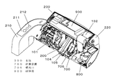
図1は本実施の形態における衛生洗浄装置を便器上に設置した状態の外観の斜視図を示し、図2は衛生洗浄装置の本体ケースの前面カバーをはずした状態の本体内部の斜視図を示すものである。
(Embodiment 1)
FIG. 1 shows a perspective view of the appearance of the sanitary washing apparatus according to the present embodiment installed on a toilet, and FIG. 2 shows a perspective view of the inside of the main body with the front cover of the main body case of the sanitary washing apparatus removed. Is.
<1>衛生洗浄装置の構成
図1に示すように、衛生洗浄装置100は、本体200、便蓋300、便座400、リモートコントローラ500により構成され、本体200、便蓋300、便座400は一体で構成され便器110の上面に設置される。
<1> Configuration of Sanitary Washing Device As shown in FIG. 1, the
本体200には、便蓋300および便座400が電動の便座便蓋回動機構102を介して開閉可能に取り付けられている。図1に示すように便蓋300を開放した状態においては、便蓋300は衛生洗浄装置100の最後部に位置するように起立する。また、便蓋300を閉塞すると便座400の上面を隠蔽する。便座400は便座ヒータ(図示せず)を内蔵しており、便座400の着座面が快適な温度になるように加熱する。
A
また、便座400の回動軸を支持する軸受部分には便座400に着座した人体を検知する着座検知スイッチ(図示せず)が設置されている。この着座検知スイッチは、便座400に使用者が着座することによる重量変化でスイッチを開閉させることにより、便座400上に使用者が着座していることを検知するものである。
In addition, a seating detection switch (not shown) for detecting a human body seated on the
また図1に示すように、本体200の側部には突出部210が設けてあり、突出部210の上面には複数の操作スイッチ212を備えた操作部211が設けられている。
As shown in FIG. 1, a
リモートコントローラ500には、衛生洗浄装置の各機能の操作と設定を行う複数の操作スイッチ501と、トイレルームに入室した使用者を検知する人体検知センサ502が
設けられている。リモートコントローラ500は便座400に着座した使用者が操作可能なトイレ室の壁面等の場所に取り付けられ、操作信号は無線を介して本体200に送信される。
The
なお、本実施の形態においては衛生洗浄装置の本体200の設置側を後方、便座400の設置側を前方とし、後方より前方に向かって右側を右方、左側を左方として各構成要素の配置を説明する。
In this embodiment, the installation side of the
図2に示すように、本体200の内部には、右側には洗浄手段を構成する熱交換器等で構成された洗浄水供給機構101が設置されており、中央部にはノズル装置103が設置されており、左側には洗浄後の局部を乾燥する乾燥装置700と便器110内の臭気を脱臭する脱臭装置800と便蓋300と便座400を電動で回動する便座便蓋回動機構102が設置されており、上部に機能部材を電気的に制御する制御部900等が設置されている。
As shown in FIG. 2, inside the
洗浄手段は洗浄水供給機構101とノズル装置103で構成されており、水道配管から供給される洗浄水を洗浄水供給機構101の熱交換器で加熱した温水をノズル装置103に供給し、ノズル装置103から使用者の局部に向けて温水を噴出し、使用者の局部を洗浄するものである。
The cleaning means includes a cleaning
ノズル装置103は、お尻を洗浄するお尻洗浄ノズル部と女性の局部を洗浄するビデノズル部を有する洗浄ノズル104と、洗浄ノズル104を本体200内に収容した収納位置と本体200から突出して洗浄動作を行う洗浄位置との間を進退移動する駆動手段(図示せず)と、熱交換器からの洗浄水を洗浄ノズルに切換えて供給する流調弁(図示せず)等が一体に組み込まれている。
The nozzle device 103 has a
ノズル装置103の先端部には開閉自在のノズルシャッター105が設置されており、洗浄ノズル104の進退移動に伴って開閉し、洗浄ノズル104が本体200に収納されている間はノズルシャッター105が閉塞することにより、用便等により洗浄ノズル104が汚染されることを抑制する構成となっている。
A
乾燥装置700は、ノズル装置103に隣接して設置されている。乾燥装置700の噴出口706は、本体200の前面下部に配置されており、噴出口706の前方には、開閉自在の乾燥シャッター750が設置されており、乾燥装置700の不使用時は閉塞して乾燥装置700の内部へ洗浄水等が侵入することを防止し、乾燥装置700の駆動時には、乾燥装置700から噴出される風圧により開放される構成となっている。乾燥装置の詳細な構成は後述する。
The
制御部900は、衛生洗浄装置100の各機能の操作を行うリモートコントローラ500の操作スイッチ501と本体200の操作スイッチ212および着座検知スイッチ(図示せず)から送信される信号に基づいて、衛生洗浄装置100の各部の動作を制御する。
The
本発明の衛生洗浄装置100はトイレ室に使用者が存在しない場合は、便座ヒータへの通電を停止、もしくは20℃程度の低温に保温している。トイレ室に使用者が入室すると、人体検知センサ502からの信号を受け、便座ヒータに通電を行う。便座ヒータは800W程度の非常に高出力のヒータであり、使用者がトイレ室に入室してから便座に着座するまでの6秒から10秒程度の間に、便座400の着座面を40℃程度の適温に温める。便座400が適温に達した後は、便座ヒータへの通電を50W程度の低ワットに下げ、適温を保つ。使用者がトイレルーム内から出ると、便座ヒータへの通電を停止、もしくは20℃程度の低温保温となる。つまり、トイレルームに使用者がいないときの電力を大幅に
削減した便座装置である。
When there is no user in the toilet room, the
<2>乾燥装置の構成
図3は本発明の実施の形態1における乾燥装置の外観の斜視図を示すものであり、図4は乾燥装置の不使用時の断面図を示すものであり、図5は静電霧化装置の断面図を示すものであり、図6は乾燥装置の乾燥機能の動作時における乾燥シャターが全開の状態の乾燥装置の断面図を示すものであり、図7は乾燥装置の静電霧化機能の動作時における乾燥シャターが半開の状態の乾燥装置の断面図を示すものである。
<2> Configuration of Drying Device FIG. 3 shows a perspective view of the appearance of the drying device according to
図3に示すように、乾燥装置700は、内部に風路が形成されたケース710と、風路に空気を送給する送風装置720と、送風装置720で送給された空気を加熱するヒータユニット730と、帯電微粒子水を生成する静電霧化装置740とを主構成部材としている。
As shown in FIG. 3, the
ケース710は難燃性樹脂で成型した下ケース711と中ケース712と上ケース713とで構成され、内部に上下二段のトンネル状の風路が形成されており、後端部には送風装置720を収容する送風装置設置スペース704が形成されている。送風装置設置スペース704の前方には送風装置720から送給された空気が流入する吸気口705が上下二段位に分かれて形成されている。ケース710の前端部には略長方形の噴出口706が開口しており、噴出口706は本体200の前面下部に配置されている。
The
図3の矢印Aに示すように乾燥装置700は送風装置720の側面から吸気して、矢印Bで示すように前面に設けた噴出口706から前方に向かって噴出する構成となっている。
As shown by an arrow A in FIG. 3, the
風路は、下ケース711と中ケース712で形成されてケース710の下方に配置された主風路701と、中ケース712と上ケース713で形成されてケース710の上方に配置された副風路702と、噴出口706の近傍で主風路701と副風路702が合流した噴出風路703で構成されており、送風装置720から送給される空気の約90%が主風路701に、約10%が副風路702に送給される。
The air path is formed by a
図3に示すように、主風路701と噴出風路703の境界部分には、上下二段の回動自在な防水シャッター707、708が設置されている。防水シャッター707、708は樹脂材料で成型された略板状であり、上辺の左右に形成された枢支軸を介してケース710に回動自在に枢支されている。
As shown in FIG. 3, at the boundary portion between the
また、乾燥装置700の噴出口706に対向する本体ケース220の下端部には開閉自在な乾燥シャッター750が設置されている。乾燥シャッター750は樹脂材料で成型された略板状であり、上辺の左右に形成された枢支軸を介して本体ケース220に回動自在に枢支されている。
In addition, an openable /
図3に示すように、乾燥装置700を使用しないときは、乾燥シャッター750は自重により略鉛直位置に配置されて乾燥装置700の噴出口706を閉塞し、排便時の汚物や洗浄水が噴出口706に直接かからない構成となっている。また、防水シャッター707も乾燥シャッター750と同様に略鉛直位置に配置されて主風路701を閉塞して洗浄水の進入を確実に防止する構成となっている。
As shown in FIG. 3, when the
また、図6および図7に示すように、乾燥装置700の使用時には風圧により、乾燥シャッター750と防水シャッター707は略鉛直位置から略水平位置の間に回動して、乾燥装置700の噴出口706を開放する構成となっている。
As shown in FIGS. 6 and 7, when the drying
図3に示すように、ケース710の内部には、後方に送風装置720と、主風路701にヒータユニット730と、副風路702に静電霧化装置740と、噴出風路703に噴出される空気の温度を検知するサーミスタ760が設置されている。
As shown in FIG. 3, inside the
送風装置720は直流モータで駆動されるシロッコファンであり、供給される直流電流の電圧を変化させることにより、シロッコファンの回転数が変化することにより送風量を変化させることができる。
The
ヒータユニット730は、加熱手段である約400Wのヒータ線731と、77℃で溶断する第一温度ヒューズ732と、93℃で動作する第二温度ヒューズ733で構成されており、外郭をカバーマイカ734で覆われている。
The
螺旋状に形成したヒータ線731はカバーマイカ734の内部の外周近傍に配置されており、ヒータ線731の螺旋の中央部には、送風装置720に近い位置となる後方に第二温度ヒューズ733を、前方に第一温度ヒューズ732が配置してある。ヒータ線731と第一温度ヒューズ732と第二温度ヒューズ733は電気的に直列に接続されている。
The heater wire 731 formed in a spiral shape is disposed in the vicinity of the outer periphery inside the cover mica 734, and a second thermal fuse 733 is disposed at the rear of the heater wire 731 near the
第一温度ヒューズ732と第二温度ヒューズ733は内部の温度が異常に上昇するのを防止する温度過昇防止手段である。送風装置720が故障してロック状態となった場合等で異常上昇が発生した場合、第1のステップとして第一温度ヒューズ732が溶断してヒータへの通電を遮断するが、例えば、第一温度ヒューズ732の故障等で作動しない場合には、第2ステップとして第二温度ヒューズ733が溶断してヒータへの通電を遮断することにより、発煙や発火が発生しないようになっている。
The first temperature fuse 732 and the second temperature fuse 733 are overtemperature prevention means for preventing the internal temperature from rising abnormally. When an abnormal rise occurs, for example, when the
静電霧化装置740は図4に示すように、空気中の水分を結露させて水を生成するペルチェ素子741と、生成された水に電圧を印加する霧化電極742と、霧化電極742に対向して設けられた対極電極743とで構成されている。
As shown in FIG. 4, the
ペルチェ素子741と制御部900とは電気的に接続されており、制御部900により0〜0.6V程度の直流電流が印加される。
The
ペルチェ素子741の冷却基板には尖鋭形状の霧化電極742が設置されており、ペルチェ素子741の冷却基板に結露した水が霧化電極742に搬送される構成となっている。
A
尖鋭形状の霧化電極742と対向する位置に、霧化電極742を包囲するように略ドーム状の対極電極743が配置されており、霧化電極742と対極電極743の間には制御部900により約3500Vの直流電流が印加される。
A substantially dome-shaped
<3>乾燥装置の動作および作用
上記構成の乾燥装置の動作および作用について以下に説明する。
<3> Operation and Action of Drying Apparatus The operation and action of the drying apparatus having the above configuration will be described below.
図6は乾燥装置の乾燥機能の動作時における乾燥シャターが全開の状態の乾燥装置の断面図を示すものであり、図7は乾燥装置の静電霧化機能の動作時における乾燥シャターが半開の状態の乾燥装置の断面図を示すものである。 FIG. 6 is a cross-sectional view of the drying device in a state where the drying shutter is fully opened during the operation of the drying function of the drying device, and FIG. 7 is a diagram illustrating that the drying shutter is partially opened during the operation of the electrostatic atomization function of the drying device. A sectional view of a drying device in a state is shown.
本実施の形態における乾燥装置700は、乾燥機能と静電霧化機能の2つの機能を備えたものである。
The drying
乾燥機能は洗浄により濡れた使用者の局部を温風により乾燥するものであり、使用者の局部に直接温風を当てて乾燥する機能である。 The drying function is to dry the user's local area wet by washing with hot air, and to apply the hot air directly to the user's local area to dry.
使用者がリモートコントローラ500の乾燥機能の操作スイッチ501を操作し、乾燥機能が使用される場合、制御部900は送風装置720とヒータユニット730を駆動する。送風装置720には12Vの直流電流を供給して強パワーで駆動させる。
When the user operates the drying
図6に示すように、送風装置720で送給された空気は吸気口705に向かって送給される。送給された空気の約90%は矢印Y1に示すように主風路701に送給され、約10%は矢印Y2で示すように副風路702に送給される。主風路701に送給された空気はヒータユニット730により加熱され、加熱された温風の風力により防水シャッター707、708を略水平となるように全開にして矢印Y3に示すように噴出風路703へと送給される。
As shown in FIG. 6, the air supplied by the
一方、矢印Y2で示すように副風路702に送給された空気は副風路702を通過して矢印Y4に示すように噴出風路703へと送給される。噴出風路703で合流した空気は噴出口706より噴出される。噴出口706から噴出する温風の風力は最大となり、図5に示すように、乾燥シャッター750は風圧により略水平位置(開度約90度)まで開放され、温風は矢印Y6に示すように略水平方向に噴出し、便座400に着座した使用者の局部に向かって送給され、洗浄により濡れた局部を短時間に乾燥することができる。
On the other hand, the air supplied to the
一方、静電霧化機能を使用する場合は、制御部900は送風装置720と静電霧化装置740を駆動する。送風装置720には約7Vの直流電流を供給して強パワーの約60パーセントの弱パワーで駆動させる。
On the other hand, when the electrostatic atomization function is used, the
図7に示すように、乾燥機能の使用時と同様に、送風装置720で送給された空気は吸気口705に向かって送給される。送給された空気の約90%は矢印Y1に示すように主風路701に送給され、約10%は矢印Y2で示すように副風路702に送給される。主風路701に送給された空気は主風路701を通過し、風力により防水シャッター707、708を略水平となるように全開にして加熱されない空気が噴出風路703へと送給される。
As shown in FIG. 7, the air supplied by the
一方、矢印Y2で示すように副風路702に送給された空気は、静電霧化装置により生成された帯電微粒子水が付加され空気が噴出風路703へと送給される。
On the other hand, as shown by the
噴出口706から噴出される帯電微粒子水を含む空気は風力が弱いため、乾燥シャッター750は乾燥機能の使用時の開度より小さい40度〜45度の開度に開放され、噴出口706から噴出した空気は乾燥シャッター750に当たって矢印Y6で示すように下方に方向を変えて、便器110の内部に向かって送給される。
Since the air containing the charged fine particle water ejected from the
特に、前記構成の静電霧化装置で生成される帯電微粒子水はナノメータサイズと非常に小さいため、広い範囲に拡散が可能であるとともに、細孔内部や狭い隙間等に入り込むことが可能である。このため、表面に付着したものはもちろん狭い隙間に入り込んだ臭気物質、カビ類、菌類に対して脱臭効果、除菌効果、殺菌効果が得られるのである。 In particular, the charged fine particle water generated by the electrostatic atomizer having the above-described configuration is very small and has a nanometer size, so that it can be diffused over a wide range and can enter the inside of a pore or a narrow gap. . Therefore, a deodorizing effect, a disinfecting effect, and a bactericidal effect can be obtained against odorous substances, molds, and fungi that have entered the narrow gap as well as those adhered to the surface.
ナノメータサイズの帯電微粒子水は、アンモニア、アセトアルデヒド、酢酸、メタン、一酸化炭素、一酸化窒素、ホルムアルデヒド等の臭気物質の分解除去と各種菌類への殺菌効果を備えており、トイレルーム内に浮遊および壁面や床面に付着した臭気物質や菌類に対して脱臭と除菌および殺菌の効果を発揮することができる。 Nanometer-sized charged fine particle water has the ability to decompose and remove odorous substances such as ammonia, acetaldehyde, acetic acid, methane, carbon monoxide, nitric oxide, formaldehyde and sterilize various fungi. Deodorizing, sterilizing and sterilizing effects can be exerted on odorous substances and fungi adhering to the wall surface and floor surface.
上記のように、1個の送風装置720を共用しながら、乾燥機能を使用する場合は人体に向かって略水平方向に送風し、静電無化機能を使用する場合には便器内に向かって下方に送風することが可能であり、多機能な乾燥装置を小型でシンプルな構成で実施することができ、コンパクトでありながら使い勝手のよい衛生洗浄装置を提供することができる。
As described above, when using a drying function while sharing one
<4>衛生洗浄装置の動作および作用
以上のように構成された衛生洗浄装置について、以下その動作、作用を説明する。
<4> Operation and Action of Sanitary Washing Apparatus The operation and action of the sanitary washing apparatus configured as described above will be described below.
使用者がトイレルームに入室し、人体検知センサ502が人体を検知すると、人体検知センサ502の信号により、制御部900は便座便蓋回動機構102を駆動して便蓋300を開放するするとともに、便座の便座ヒータへの通電を開始して便座400の着座面が着座に適した40℃程度になるように、10秒以内に昇温させる。
When the user enters the toilet room and the human
使用者が、便座400に着座すると、着座検知スイッチが着座を検知し、制御部900が着座信号を受信することにより、本体200の操作スイッチ212およびリモートコントローラ500の操作スイッチ501により洗浄機能と乾燥機能の操作が可能となる。
When the user sits on the
また、制御部900は脱臭装置800の送風機の駆動を開始する。脱臭装置800は、本体200の底面に設けられた吸気口から便器110内の空気を吸引し、脱臭体のハニカム孔をおよび送風機内を通過させて本体の後方より排気される。
Moreover, the
この間、脱臭装置に吸引された臭気物質を含んだ空気は、脱臭体のハニカム孔を通過する間に、臭気物質がハニカム孔の孔壁に吸着され、脱臭体の触媒作用により臭気物質が分解除去され、脱臭体を通過後の空気は臭気物質を除去されたほとんど無臭状態となり、排気口からトイレルーム内に放出される。 During this time, the air containing the odorous substance sucked into the deodorizing device is adsorbed on the hole wall of the honeycomb hole while passing through the honeycomb hole of the deodorizing body, and the odorous substance is decomposed and removed by the catalytic action of the deodorizing body. The air after passing through the deodorizing body becomes almost odorless from which the odorous substance is removed, and is discharged into the toilet room from the exhaust port.
上記のように、用便中に便器内で発生する臭気物質の多くは、脱臭装置により分解除去されトイレルーム全体に臭気が拡散されることを効果的に抑制することができる。 As described above, most of the odorous substances generated in the toilet in the toilet can be effectively prevented from being decomposed and removed by the deodorizing device and odors being diffused throughout the toilet room.
使用者が用便終了後に、リモートコントローラ500の操作スイッチ501により洗浄操作を行うことにより、洗浄ノズルが本体200より進出し、洗浄水を噴出することにより使用者の局部を洗浄し、洗浄終了の操作により局部の洗浄は終了し、洗浄ノズルは本体200内に収納される。
After the user finishes the flight, the cleaning operation is performed by the
次に、使用者がリモートコントローラ500の操作スイッチ501により乾燥機能の操作を行うと、制御部900は乾燥装置700の送風装置720とヒータユニット730を駆動して乾燥動作を開始する。このとき送風装置720には12Vの直流電流が供給され強パワーで駆動される。送風装置720でヒータユニット730へ送給された空気はヒータユニット730で加熱されて温風となって噴出口706より噴出し、風圧により乾燥シャッター750を全開して使用者の局部に向かって噴出し、洗浄で濡れた使用者の局部を乾燥する。
Next, when the user operates the drying function with the
使用者が用便動作を全て終了した後に便座から立ち上がり、トイレルームから退出して人体検知センサ502が人体の検知を終了してから、所定時間経過後(本実施の形態においては5分後)に、制御部900は脱臭装置800の駆動を停止するとともに便座便蓋回動機構102を駆動して便蓋300を閉塞させる。
After the user completes the toilet operation, the user gets up from the toilet seat, exits the toilet room, and after the human
便蓋300が閉塞すると、制御部900は、乾燥装置700の静電霧化機能を駆動するため送風装置720と静電霧化装置740の通電を開始する。このとき送風装置720には7Vの直流電流が供給され弱パワーで駆動される。
When the
乾燥装置700の噴出口706より噴出した帯電微粒子水を含む空気は、乾燥シャッター750に当たって下方に向きを変え、便器110の内部に送給される。便器110の内部に送給された帯電微粒子水を含む空気は、便器110内部と便蓋300で閉塞された空間に充満するとともに、一部は便座400の下面と便器110の上面との隙間からトイレルーム空間に放出される。
The air containing the charged fine particle water ejected from the
便器110内部と便蓋300で閉塞された空間に充満した帯電微粒子水により、便器110の内面および便座400の外面および便蓋300の内面に付着した臭気物質や菌類に対して脱臭と除菌および殺菌の効果を発揮する。
Due to the charged fine particle water filled in the
また、トイレルーム空間に放出された帯電微粒子水はトイレルーム内に浮遊する臭気物質や、床面および壁面に付着した臭気物質やカビ類に対しても脱臭効果や防カビ効果を発揮する。 In addition, the charged fine particle water released into the toilet room exhibits a deodorizing effect and an antifungal effect against odorous substances floating in the toilet room and odorous substances and molds adhering to the floor and wall surfaces.
一方、使用者が便座400に着座しない男子小用の場合は、脱臭装置800は駆動されないが、使用者のトイレルームからの退室後、人体検知センサが人体の検知を終了してから、所定時間経過後(本実施の形態においては5分後)に、便座便蓋回動機構102を駆動して便蓋300を閉塞させるとともに、前記同様に乾燥装置700の送風装置720と静電霧化装置740の通電を開始する。
On the other hand, when the user does not sit on the
乾燥装置700の静電霧化機能の運転が開始して20分後に、制御部900は静電霧化装置740の通電を停止して送風装置720のみの駆動を継続し、5分後に送風装置720の駆動を停止させて静電霧化機能の運転を終了させる。運転終了時に送風装置720のみの駆動を継続することにより、帯電微粒子水の生成時に発生するオゾンを拡散して希釈し、不快なオゾン臭を弱めることができる。
20 minutes after the operation of the electrostatic atomization function of the
前記静電霧化機能の運転は、衛生洗浄装置100の全使用時に実施されるものではなく、本実施の形態においては1日に10回に限定されている。衛生洗浄装置の通常の1回の使用時間は長くても数分であるのに対し、静電霧化機能の1回の運転時間は約20分であるため洗浄機能等と比較して相対的に長く、使用状態によっては、特に送風装置と他の機能部材との耐久性のバランスが大きく崩れることが推察され、全機能の耐久性のバランスを維持する目的で運転回数を限定している。
The operation of the electrostatic atomization function is not performed when the
なお、本実施の形態においては、乾燥機能と静電霧化機能とは送風の風路の一部を噴出口の近傍で共用する構成としたが、これに限るものではなく、乾燥機能と静電霧化機能の風路を噴出口まで別風路で構成してもよい。 In the present embodiment, the drying function and the electrostatic atomization function are configured to share a part of the air flow path in the vicinity of the jet outlet, but the present invention is not limited to this. You may comprise the air path of an electric atomization function by another air path to a jet nozzle.
また、本実施の形態においては、シャッターの開閉動作は送風装置の送風による風力を駆動力として実施する構成としたが、これに限るものではなく、別途設けたモータ等の駆動力を使用する構成としてもよい。 Further, in the present embodiment, the shutter opening / closing operation is configured to implement wind power generated by the blower of the air blower as the driving force. However, the present invention is not limited to this, and a configuration using a driving force such as a separately provided motor is used. It is good.
以上のように、本発明にかかる衛生洗浄装置は、乾燥装置と静電霧化装置の設置スペースを縮小することが可能となるので、他の静電霧化機能を備えた送風機器の用途にも適用できる。 As described above, the sanitary washing device according to the present invention can reduce the installation space of the drying device and the electrostatic atomizer, so that it can be used for other blower devices having an electrostatic atomization function. Is also applicable.
100 衛生洗浄装置
110 便器
200 本体
400 便座
700 乾燥装置
701 主風路(風路)
702 副風路(風路)
703 噴出風路(風路)
706 噴出口
710 ケース
720 送風装置
730 ヒータユニット(ヒータ)
740 静電霧化装置
750 乾燥シャッター(シャッター)
900 制御部
DESCRIPTION OF
702 Secondary wind path (wind path)
703 Spouting wind path (wind path)
706
740
900 Control unit
Claims (6)
前記本体に起倒自在に枢支された便座と、
人体局部を洗浄する洗浄手段と、
人体局部を乾燥する乾燥装置と、
前記乾燥装置の駆動に伴い開閉されるシャッターと、
少なくとも前記洗浄手段と乾燥装置を制御する制御部と、を含み、
前記乾燥装置は、風路を形成するケースと、空気を送給する送風装置と、空気を加熱するヒータと、帯電微粒子水を生成する静電霧化装置と、を備え、
前記制御部は、前記ヒータの駆動時と前記静電霧化装置の駆動時とでは、前記シャッターの開度が異なるように制御することを特徴とする、
衛生洗浄装置。 A body placed on the toilet,
A toilet seat pivotably supported by the main body;
A cleaning means for cleaning the human body part;
A drying device for drying the human body part;
A shutter that is opened and closed as the drying device is driven;
Including at least the cleaning means and a controller for controlling the drying device,
The drying device includes a case that forms an air passage, a blower that feeds air, a heater that heats the air, and an electrostatic atomizer that generates charged fine particle water,
The control unit controls the opening degree of the shutter to be different between when the heater is driven and when the electrostatic atomizer is driven.
Sanitary washing device.
請求項1に記載の衛生洗浄装置。 The control unit controls the opening of the shutter to be larger when the heater is driven than when the electrostatic atomizer is driven.
The sanitary washing device according to claim 1.
請求項1または2に記載の衛生洗浄装置。 The shutter is configured to be opened by wind power fed by the blower.
The sanitary washing device according to claim 1 or 2.
請求項3に記載の衛生洗浄装置。 The shutter is formed in a rotatable substantially plate shape whose upper edge is pivotally supported, and is configured to be rotatable between a substantially vertical position and a substantially horizontal position.
The sanitary washing device according to claim 3.
請求項4に記載の衛生洗浄装置。 The shutter is configured to rotate to a substantially horizontal position when the heater is driven, and to rotate to an intermediate position between a horizontal position and a vertical position when the electrostatic atomizer is driven.
The sanitary washing device according to claim 4.
請求項1〜5のいずれか1項に記載の衛生洗浄装置。 The blower is arranged upstream of the air passage, and the heater and the electrostatic atomizer are arranged in parallel downstream of the blower,
The sanitary washing device according to any one of claims 1 to 5.
Priority Applications (2)
| Application Number | Priority Date | Filing Date | Title |
|---|---|---|---|
| JP2014033757A JP2015158103A (en) | 2014-02-25 | 2014-02-25 | sanitary washing device |
| CN201510081270.4A CN104863229B (en) | 2014-02-25 | 2015-02-15 | Sanitary washing equipment |
Applications Claiming Priority (1)
| Application Number | Priority Date | Filing Date | Title |
|---|---|---|---|
| JP2014033757A JP2015158103A (en) | 2014-02-25 | 2014-02-25 | sanitary washing device |
Publications (1)
| Publication Number | Publication Date |
|---|---|
| JP2015158103A true JP2015158103A (en) | 2015-09-03 |
Family
ID=53909361
Family Applications (1)
| Application Number | Title | Priority Date | Filing Date |
|---|---|---|---|
| JP2014033757A Pending JP2015158103A (en) | 2014-02-25 | 2014-02-25 | sanitary washing device |
Country Status (2)
| Country | Link |
|---|---|
| JP (1) | JP2015158103A (en) |
| CN (1) | CN104863229B (en) |
Cited By (13)
| Publication number | Priority date | Publication date | Assignee | Title |
|---|---|---|---|---|
| JP2017198031A (en) * | 2016-04-28 | 2017-11-02 | 株式会社Lixil | Sanitary device |
| JP2018031124A (en) * | 2016-08-22 | 2018-03-01 | Toto株式会社 | Sanitary washing device |
| JP2019112923A (en) * | 2017-12-22 | 2019-07-11 | Toto株式会社 | Toilet seat device and toilet device |
| JP2019112924A (en) * | 2017-12-22 | 2019-07-11 | Toto株式会社 | Toilet seat device and toilet device |
| JP2019112922A (en) * | 2017-12-22 | 2019-07-11 | Toto株式会社 | Toilet device and toilet seat device |
| US10563388B2 (en) | 2017-12-22 | 2020-02-18 | Toto Ltd. | Toilet device and toilet seat device |
| US10584469B2 (en) | 2017-12-22 | 2020-03-10 | Toto Ltd. | Toilet seat device and toilet device |
| US10590639B2 (en) | 2017-12-22 | 2020-03-17 | Toto Ltd. | Toilet seat device and toilet device |
| JP2020171466A (en) * | 2019-04-10 | 2020-10-22 | Toto株式会社 | Toilet seat device |
| JP2020171468A (en) * | 2019-04-10 | 2020-10-22 | Toto株式会社 | Toilet seat device |
| JP2020171467A (en) * | 2019-04-10 | 2020-10-22 | Toto株式会社 | Toilet seat device |
| WO2022150703A1 (en) * | 2021-01-08 | 2022-07-14 | Saneex Llc | Auto cleaning toilet seat assembly |
| EP4141179A1 (en) * | 2021-08-23 | 2023-03-01 | Toto Ltd. | Sanitary cleaning device |
Families Citing this family (2)
| Publication number | Priority date | Publication date | Assignee | Title |
|---|---|---|---|---|
| JP7113173B2 (en) * | 2018-07-12 | 2022-08-05 | パナソニックIpマネジメント株式会社 | sanitary washing equipment |
| CN113729535B (en) * | 2020-05-27 | 2023-09-08 | 厦门优胜卫厨科技有限公司 | Drying device of electronic toilet |
Family Cites Families (9)
| Publication number | Priority date | Publication date | Assignee | Title |
|---|---|---|---|---|
| JP4333339B2 (en) * | 2003-11-25 | 2009-09-16 | パナソニック株式会社 | Toilet seat device |
| JP2006097311A (en) * | 2004-09-29 | 2006-04-13 | Sanyo Electric Co Ltd | Flush toilet and deodorizing method of flush toilet |
| JP4807298B2 (en) * | 2007-03-27 | 2011-11-02 | パナソニック電工株式会社 | Toilet seat device |
| JP4752798B2 (en) * | 2007-03-27 | 2011-08-17 | パナソニック電工株式会社 | Electrostatic atomizer |
| JP2008240376A (en) * | 2007-03-27 | 2008-10-09 | Matsushita Electric Works Ltd | Toilet seat device |
| JP5180503B2 (en) * | 2007-03-27 | 2013-04-10 | パナソニック株式会社 | Electrostatic atomizer |
| JP2009002033A (en) * | 2007-06-21 | 2009-01-08 | Panasonic Corp | Toilet utilization device |
| JP2012144876A (en) * | 2011-01-11 | 2012-08-02 | Panasonic Corp | Sanitary washing device |
| JP5810277B2 (en) * | 2011-03-25 | 2015-11-11 | パナソニックIpマネジメント株式会社 | Sanitary washing device |
-
2014
- 2014-02-25 JP JP2014033757A patent/JP2015158103A/en active Pending
-
2015
- 2015-02-15 CN CN201510081270.4A patent/CN104863229B/en active Active
Cited By (18)
| Publication number | Priority date | Publication date | Assignee | Title |
|---|---|---|---|---|
| JP2017198031A (en) * | 2016-04-28 | 2017-11-02 | 株式会社Lixil | Sanitary device |
| US10145094B2 (en) | 2016-04-28 | 2018-12-04 | Lixil Corporation | Sanitary apparatus with a hot air blower equipped with an ion generating device for disinfection, deodorization, or the like |
| JP2018031124A (en) * | 2016-08-22 | 2018-03-01 | Toto株式会社 | Sanitary washing device |
| US10584469B2 (en) | 2017-12-22 | 2020-03-10 | Toto Ltd. | Toilet seat device and toilet device |
| TWI695104B (en) * | 2017-12-22 | 2020-06-01 | 日商Toto股份有限公司 | Toilet seat device and toilet flushing device |
| JP2019112922A (en) * | 2017-12-22 | 2019-07-11 | Toto株式会社 | Toilet device and toilet seat device |
| TWI683050B (en) * | 2017-12-22 | 2020-01-21 | 日商Toto股份有限公司 | Toilet seat device and toilet flushing device |
| US10563388B2 (en) | 2017-12-22 | 2020-02-18 | Toto Ltd. | Toilet device and toilet seat device |
| JP2019112923A (en) * | 2017-12-22 | 2019-07-11 | Toto株式会社 | Toilet seat device and toilet device |
| US10590639B2 (en) | 2017-12-22 | 2020-03-17 | Toto Ltd. | Toilet seat device and toilet device |
| JP2019112924A (en) * | 2017-12-22 | 2019-07-11 | Toto株式会社 | Toilet seat device and toilet device |
| JP2020171466A (en) * | 2019-04-10 | 2020-10-22 | Toto株式会社 | Toilet seat device |
| JP2020171468A (en) * | 2019-04-10 | 2020-10-22 | Toto株式会社 | Toilet seat device |
| JP2020171467A (en) * | 2019-04-10 | 2020-10-22 | Toto株式会社 | Toilet seat device |
| JP7236053B2 (en) | 2019-04-10 | 2023-03-09 | Toto株式会社 | toilet seat device |
| JP7342405B2 (en) | 2019-04-10 | 2023-09-12 | Toto株式会社 | toilet seat device |
| WO2022150703A1 (en) * | 2021-01-08 | 2022-07-14 | Saneex Llc | Auto cleaning toilet seat assembly |
| EP4141179A1 (en) * | 2021-08-23 | 2023-03-01 | Toto Ltd. | Sanitary cleaning device |
Also Published As
| Publication number | Publication date |
|---|---|
| CN104863229B (en) | 2019-04-12 |
| CN104863229A (en) | 2015-08-26 |
Similar Documents
| Publication | Publication Date | Title |
|---|---|---|
| JP2015158103A (en) | sanitary washing device | |
| JP5936482B2 (en) | Ion generator and toilet seat device incorporating the same | |
| JP6322808B2 (en) | Sanitary washing device | |
| JP5810277B2 (en) | Sanitary washing device | |
| JP6099219B2 (en) | Toilet seat device incorporating an ion generator | |
| US10100504B2 (en) | Bidet apparatus | |
| JP7054043B2 (en) | Toilet seat device | |
| JP2015187361A (en) | sanitary washing device | |
| JP5684068B2 (en) | Sanitary washing device | |
| JP5842149B2 (en) | Sanitary washing device | |
| JP5533747B2 (en) | Sanitary washing device | |
| JP6099233B1 (en) | Ion generator | |
| JP6587220B2 (en) | Toilet seat device and toilet device | |
| JP5533720B2 (en) | Sanitary washing device | |
| JP7054042B2 (en) | Toilet seat device | |
| JP5845402B2 (en) | Sanitary washing device | |
| JP2012144876A (en) | Sanitary washing device | |
| JP2007023769A (en) | Method of controlling aroma in sanitary washing device | |
| JP7390902B2 (en) | Toilet seat device and program | |
| JP5938567B2 (en) | Sanitary washing device | |
| JP7154486B2 (en) | toilet equipment | |
| JP6587221B2 (en) | Toilet seat device and toilet device | |
| JP2012225055A5 (en) | ||
| JP6996283B2 (en) | Toilet seat device | |
| JP6587219B2 (en) | Toilet device and toilet seat device |
Legal Events
| Date | Code | Title | Description |
|---|---|---|---|
| RD01 | Notification of change of attorney |
Free format text: JAPANESE INTERMEDIATE CODE: A7421 Effective date: 20160519 |