JP2015156283A - LED lighting module - Google Patents
LED lighting module Download PDFInfo
- Publication number
- JP2015156283A JP2015156283A JP2014030403A JP2014030403A JP2015156283A JP 2015156283 A JP2015156283 A JP 2015156283A JP 2014030403 A JP2014030403 A JP 2014030403A JP 2014030403 A JP2014030403 A JP 2014030403A JP 2015156283 A JP2015156283 A JP 2015156283A
- Authority
- JP
- Japan
- Prior art keywords
- led
- module according
- lighting module
- led lighting
- light emitting
- Prior art date
- Legal status (The legal status is an assumption and is not a legal conclusion. Google has not performed a legal analysis and makes no representation as to the accuracy of the status listed.)
- Pending
Links
Images


Classifications
-
- F—MECHANICAL ENGINEERING; LIGHTING; HEATING; WEAPONS; BLASTING
- F21—LIGHTING
- F21K—NON-ELECTRIC LIGHT SOURCES USING LUMINESCENCE; LIGHT SOURCES USING ELECTROCHEMILUMINESCENCE; LIGHT SOURCES USING CHARGES OF COMBUSTIBLE MATERIAL; LIGHT SOURCES USING SEMICONDUCTOR DEVICES AS LIGHT-GENERATING ELEMENTS; LIGHT SOURCES NOT OTHERWISE PROVIDED FOR
- F21K9/00—Light sources using semiconductor devices as light-generating elements, e.g. using light-emitting diodes [LED] or lasers
- F21K9/20—Light sources comprising attachment means
-
- H—ELECTRICITY
- H01—ELECTRIC ELEMENTS
- H01L—SEMICONDUCTOR DEVICES NOT COVERED BY CLASS H10
- H01L2224/00—Indexing scheme for arrangements for connecting or disconnecting semiconductor or solid-state bodies and methods related thereto as covered by H01L24/00
- H01L2224/01—Means for bonding being attached to, or being formed on, the surface to be connected, e.g. chip-to-package, die-attach, "first-level" interconnects; Manufacturing methods related thereto
- H01L2224/42—Wire connectors; Manufacturing methods related thereto
- H01L2224/47—Structure, shape, material or disposition of the wire connectors after the connecting process
- H01L2224/48—Structure, shape, material or disposition of the wire connectors after the connecting process of an individual wire connector
- H01L2224/481—Disposition
- H01L2224/48135—Connecting between different semiconductor or solid-state bodies, i.e. chip-to-chip
- H01L2224/48137—Connecting between different semiconductor or solid-state bodies, i.e. chip-to-chip the bodies being arranged next to each other, e.g. on a common substrate
-
- H—ELECTRICITY
- H01—ELECTRIC ELEMENTS
- H01L—SEMICONDUCTOR DEVICES NOT COVERED BY CLASS H10
- H01L33/00—Semiconductor devices with at least one potential-jump barrier or surface barrier specially adapted for light emission; Processes or apparatus specially adapted for the manufacture or treatment thereof or of parts thereof; Details thereof
- H01L33/48—Semiconductor devices with at least one potential-jump barrier or surface barrier specially adapted for light emission; Processes or apparatus specially adapted for the manufacture or treatment thereof or of parts thereof; Details thereof characterised by the semiconductor body packages
- H01L33/58—Optical field-shaping elements
Abstract
Description
本発明は、LED照明モジュールに関する。 The present invention relates to an LED lighting module.
室内照明は、室内全体を照らすもの、室内の一部を照らすものなど、様々な種類のものが提案されている。ダウンライトは、天井に埋め込まれる照明器具の一種であり、主に床面の所望の部位を照らすために用いられる。近年においては、ダウンライトの光源としてLEDチップが用いられたLED照明器具が開発されている。特許文献1には、ダウンライトとして用いられるLED照明器具が開示されている。このLED照明器具は、LED照明モジュールを備えている。LED照明モジュールは、複数のLEDチップとこれらのLEDチップを保持するケースと、複数のLEDチップからの光を透過させるカバーと、口金とを備えている。上記カバーは、平面視円形状であり、上記複数のLEDチップからの光を透過させつつ拡散させる。カバーの正面は、円形平面とされている。上記口金は、たとえばIEC規格のGX53形であり、天井の開口部分奥方に設けられた給電部に上記LED照明モジュールを着脱自在とするものである。上記LED照明モジュールが上記給電部に取り付けられることによって、天井に埋め込まれたダウンライトとして機能するLED照明器具が構成される。
Various types of indoor lighting have been proposed, such as those that illuminate the entire room and those that illuminate a part of the room. A downlight is a type of lighting fixture embedded in a ceiling, and is mainly used to illuminate a desired portion of a floor surface. In recent years, LED lighting fixtures using LED chips as light sources for downlights have been developed.
上記LED照明モジュールの上記給電部への着脱は、上記LED照明モジュールを上記給電部に対して回転させる動作を含んでいる。上記LED照明モジュールを上記天井の上記開口部分奥方に位置させると、使用者は上記カバーの正面にある上記円形平面に触れることにより上記LED照明モジュールを支える格好となる。上記円形平面に触れることのみで上記LED照明モジュールを回転させることは容易ではなく、上記LED照明モジュールの取り付けおよび取替え作業が困難となるという問題があった。 The attachment / detachment of the LED illumination module to / from the power supply unit includes an operation of rotating the LED illumination module with respect to the power supply unit. When the LED lighting module is positioned at the back of the opening portion of the ceiling, the user touches the circular plane on the front surface of the cover to support the LED lighting module. It is not easy to rotate the LED lighting module only by touching the circular plane, and there is a problem that it is difficult to attach and replace the LED lighting module.
本発明は、上記した事情のもとで考え出されたものであって、給電部への着脱をより容易に行うことが可能なLED照明モジュールを提供することをその課題とする。 The present invention has been conceived under the circumstances described above, and an object thereof is to provide an LED illumination module that can be easily attached to and detached from the power feeding unit.
本発明によって提供されるLED照明モジュールは、1以上のLEDチップを有するLED発光部と、上記LED発光部を支持するケースと、上記LED発光部とは反対側に設けられ、給電部に対して着脱可能である口金と、上記LED発光部からの光を透過させるカバーと、を備えたLED照明モジュールであって、上記口金と上記給電部との着脱は、上記口金を上記給電部に対して相対回転させる動作を含んでおり、上記カバーは、上記LED発光部の光が出射させる方向に膨出しているとともに、上記相対回転の回転軸周りの周方向に沿って設けられた高摩擦部を有することを特徴としている。 The LED illumination module provided by the present invention is provided on the opposite side of the LED light emitting unit, the LED light emitting unit having one or more LED chips, a case supporting the LED light emitting unit, and the power supply unit. An LED illumination module comprising a base that can be attached and detached, and a cover that transmits light from the LED light emitting unit, wherein the base and the power supply unit are attached to and detached from the power supply unit. The cover includes a relatively rotating operation, and the cover bulges in a direction in which the light emitted from the LED light emitting portion is emitted, and a high friction portion provided along a circumferential direction around the rotation axis of the relative rotation. It is characterized by having.
本発明の好ましい実施の形態においては、上記高摩擦部は、上記周方向の全周に形成されている。 In preferable embodiment of this invention, the said high friction part is formed in the perimeter of the said circumferential direction.
本発明の好ましい実施の形態においては、上記高摩擦部は、各々が上記回転軸方向視において径方向に延びる複数のリブを含んでいる。 In a preferred embodiment of the present invention, the high friction portion includes a plurality of ribs each extending in the radial direction when viewed in the rotational axis direction.
本発明の好ましい実施の形態においては、上記リブの上記径方向における長さは、5mm〜20mmである。 In preferable embodiment of this invention, the length in the said radial direction of the said rib is 5 mm-20 mm.
本発明の好ましい実施の形態においては、上記リブの上記周方向における幅は、0.5mm〜2.0mmである。 In preferable embodiment of this invention, the width | variety in the said circumferential direction of the said rib is 0.5 mm-2.0 mm.
本発明の好ましい実施の形態においては、上記複数のリブの上記周方向におけるピッチは、1.0mm〜5.0mmである。 In a preferred embodiment of the present invention, the pitch in the circumferential direction of the plurality of ribs is 1.0 mm to 5.0 mm.
本発明の好ましい実施の形態においては、上記リブの高さは、0.5mm〜5mmである。 In preferable embodiment of this invention, the height of the said rib is 0.5 mm-5 mm.
本発明の好ましい実施の形態においては、上記複数のリブは、両隣の上記リブよりも高さが低い最低位リブを含む。 In a preferred embodiment of the present invention, the plurality of ribs include a lowest rib having a height lower than that of the adjacent ribs.
本発明の好ましい実施の形態においては、上記複数のリブは、上記最低位リブと、この最低位リブから上記周方向に離間するほど高さが高くなる複数の中位リブと、を含む。 In a preferred embodiment of the present invention, the plurality of ribs include the lowest rib and a plurality of middle ribs having a height that increases with distance from the lowest rib in the circumferential direction.
本発明の好ましい実施の形態においては、上記口金は、1対のピンを含んでおり、上記複数のリブのうち上記1対のピンと周方向位置が対応するものは、体積が最大である。 In a preferred embodiment of the present invention, the base includes a pair of pins, and the one of the plurality of ribs corresponding to the pair of pins in the circumferential direction has a maximum volume.
本発明の好ましい実施の形態においては、上記複数のリブのうち上記1対のピンと周方向位置が対応するものは、最も高さが高い。 In a preferred embodiment of the present invention, among the plurality of ribs, the one corresponding to the pair of pins and the circumferential position has the highest height.
本発明の好ましい実施の形態においては、上記複数のリブのうち上記1対のピンと周方向位置が対応するものは、上記径方向における長さが最も長い。 In a preferred embodiment of the present invention, among the plurality of ribs, the one corresponding to the pair of pins and the circumferential position has the longest length in the radial direction.
本発明の好ましい実施の形態においては、上記高摩擦部は、複数の突起を含む。 In a preferred embodiment of the present invention, the high friction portion includes a plurality of protrusions.
本発明の好ましい実施の形態においては、上記高摩擦部は、上記周方向において互いに離間する複数のグループに分けられている。 In a preferred embodiment of the present invention, the high friction portion is divided into a plurality of groups separated from each other in the circumferential direction.
本発明の好ましい実施の形態においては、上記カバーは、全体がドーム状に膨出している。 In a preferred embodiment of the present invention, the entire cover bulges out in a dome shape.
本発明の好ましい実施の形態においては、上記カバーは、上記LED発光部からの光を拡散させつつ透過させる。 In preferable embodiment of this invention, the said cover permeate | transmits the light from the said LED light emission part, diffusing.
本発明の好ましい実施の形態においては、上記カバーは、乳白色である。 In a preferred embodiment of the present invention, the cover is milky white.
本発明の好ましい実施の形態においては、上記LED発光部は、LED基板と、このLED基板に実装された複数のLEDチップと、これらのLEDチップを覆う封止樹脂と、を具備している。 In a preferred embodiment of the present invention, the LED light emitting section includes an LED substrate, a plurality of LED chips mounted on the LED substrate, and a sealing resin that covers these LED chips.
本発明の好ましい実施の形態においては、上記LED基板は、セラミックスからなる基材を有する。 In a preferred embodiment of the present invention, the LED substrate has a base material made of ceramics.
本発明の好ましい実施の形態においては、上記封止樹脂には、上記LEDチップからの光によって励起されることにより上記LEDチップからの光とは異なる光を発する蛍光材料が混入されており、上記LED発光部は、白色光を発する。 In a preferred embodiment of the present invention, the sealing resin is mixed with a fluorescent material that emits light different from the light from the LED chip when excited by the light from the LED chip. The LED light emitting unit emits white light.
本発明の好ましい実施の形態においては、上記複数のLEDチップは2ワイヤタイプであり、隣り合う上記LEDチップどうしが、ワイヤによって直接接続されている。 In a preferred embodiment of the present invention, the plurality of LED chips are of a two-wire type, and the adjacent LED chips are directly connected by wires.
本発明の好ましい実施の形態においては、上記複数のLEDチップのすべてが直列に接続されている。 In a preferred embodiment of the present invention, all of the plurality of LED chips are connected in series.
本発明の好ましい実施の形態においては、上記ケースおよび上記カバーは、平面視円形状である。 In a preferred embodiment of the present invention, the case and the cover are circular in plan view.
本発明の好ましい実施の形態においては、上記ケースは、金属からなる放熱部材を有する。 In a preferred embodiment of the present invention, the case has a heat radiating member made of metal.
本発明の好ましい実施の形態においては、上記ケースには、複数のフィンが形成されている。 In a preferred embodiment of the present invention, the case is formed with a plurality of fins.
このような構成によれば、膨出した上記カバーに上記高摩擦部が設けられていることにより、使用者が上記高摩擦部に指を触れた際に、まっすぐに押し当てる格好とはならず、傾斜の分だけ上記高摩擦部を介して上記カバーを挟むような触れ方を取ることができる。したがって、上記LED照明モジュールを上記軸周りによりスムーズに回転させることが可能であり、給電部への着脱をより容易に行うことができる。 According to such a configuration, since the high-friction portion is provided on the bulged cover, when the user touches the high-friction portion with a finger, it does not look straight. It is possible to take a touch such that the cover is sandwiched through the high friction portion by an amount corresponding to the inclination. Therefore, the LED illumination module can be rotated more smoothly around the axis, and can be more easily attached to and detached from the power feeding unit.
本発明のその他の特徴および利点は、添付図面を参照して以下に行う詳細な説明によって、より明らかとなろう。 Other features and advantages of the present invention will become more apparent from the detailed description given below with reference to the accompanying drawings.
以下、本発明の好ましい実施の形態につき、図面を参照して具体的に説明する。 Hereinafter, preferred embodiments of the present invention will be specifically described with reference to the drawings.
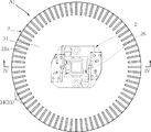
図1〜図7は、本発明の第一実施形態に基づくLED照明モジュールを示している。本実施形態のLED照明モジュールA1は、ケース1、LED発光部2、カバー3および電源部4を備えている。LED照明モジュールA1は、後述するように、天井に設けられた給電部に取り付けられることにより、たとえばダウンライトを構成するモジュールである。本実施形態においては、LED照明モジュールA1は、軸方向長さが相対的に短い略円柱形状である。
1 to 7 show an LED lighting module according to a first embodiment of the present invention. The LED illumination module A1 of this embodiment includes a
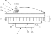
図1は、LED照明モジュールA1を示す平面図である。図2は、LED照明モジュールA1を示す側面図である。図3は、LED照明モジュールA1を示す底面図である。図4は、図1のIV−IV線に沿う断面図である。図5は、LED照明モジュールA1を示す要部拡大断面図である。図6は、図5のVI−VI線に沿う要部拡大断面図である。図7は、図5のVII−VII線に沿う要部拡大断面図である。 FIG. 1 is a plan view showing the LED illumination module A1. FIG. 2 is a side view showing the LED illumination module A1. FIG. 3 is a bottom view showing the LED illumination module A1. 4 is a cross-sectional view taken along line IV-IV in FIG. FIG. 5 is an enlarged cross-sectional view showing a main part of the LED illumination module A1. FIG. 6 is an enlarged cross-sectional view of a main part taken along line VI-VI in FIG. FIG. 7 is an enlarged cross-sectional view of a main part taken along line VII-VII in FIG.
ケース1は、LED発光部2、カバー3および電源部4を収容もしくは保持するものである。本実施形態においては、ケース1は、放熱部材11、絶縁部材12および中間ブラケット15からなる。本実施形態においては、ケース1は、平面視円形状である。
The
放熱部材11は、LED発光部2からの熱を放散することが意図された部材であり、たとえばアルミなどの金属からなる。放熱部材11は、搭載面11a、複数のフィン11bおよび係合部11cを有する。搭載面11aは、LED発光部2からの光を出射させる出射方向(図4における図中上方)を向いており、円形の略平面である。複数のフィン11bは、LED発光部2からの熱の放散を促進するためのものであり、放熱部材11の外周部分全周にわたって設けられている。フィン11bは、LED照明モジュールA1の軸方向および径方向に対して平行である。係合部11cは、搭載面11aを取り囲む円環状の部分である。係合部11cは、カバー3の取り付けに用いられる。
The
絶縁部材12は、放熱部材11に対して上記出射方向とは反対側に取り付けられており、本実施形態においては、平面視円形状である。絶縁部材12は、絶縁性材料からなり、本実施形態においては、たとえばポリブチレンテレフタレート(PBT)樹脂からなる。絶縁部材12は、凸部12aを有している。凸部12aは、上記出射方向とは反対側に突出する円柱形状部分である。図2に示すように、凸部12aには、溝部12bが形成されている。溝部12bは、上記軸方向に延びる部分と、これに続いて上記周方向に延びる部分とを有している。また、絶縁部材12には、2つのピン13が設けられている。2つのピン13は、凸部12aを挟んで上記径方向において互いに反対側に位置しており、上記出射方向とは反対側に突出している。この凸部12aと2つのピン13とによって口金14が構成されている。口金14は、後述するように、LED照明モジュールA1をたとえば天井に設けられた給電部に装着するためのものであり、たとえばIEC規格のGX53型である。
The insulating
中間ブラケット15は、放熱部材11と絶縁部材12との間に設けられている。中間ブラケット15は、絶縁性材料からなり、本実施形態においては、たとえばポリブチレンテレフタレート(PBT)樹脂からなる。中間ブラケット15は、2つのピン13および電源部4の固定保持や、2つのピン13、LED発光部2および電源部4を接続する配線などを保持する機能を果たす。
The
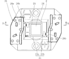
LED発光部2は、LED照明モジュールA1の光源をなすユニットである。図8〜図10に示すように、LED発光部2は、LED基板21、複数のLEDチップ22、封止樹脂24、堰部25およびホルダ26を備えている。図8は、LED発光部2の平面図である。図9は、図8のIX−IX線に沿う断面図である。図10は、LED発光部2から封止樹脂24およびホルダ26を省略した平面図である。
The LED
図10に示すように、LED基板21は、たとえば平面視矩形状であり、複数のLEDチップ22が搭載されている。LED基板21の構成は特に限定されないが、本実施形態においては、基材21aおよび配線パターン21bを有している。LED基板21は、平面視寸法がたとえば12mmX15mm程度である。
As shown in FIG. 10, the
基材21aは、絶縁性材料からなり、熱伝導率が高められたガラスエポキシ樹脂やセラミックスからなる。配線パターン21bは、複数のLEDチップ22を実装し、かつこれらのLEDチップ22への導通経路を構成する。配線パターン21bは、金属のメッキ層からなり、たとえばCu,Ni,Au,Agなどからなる。本実施形態においては、配線パターン21bは、26個の複数のLEDチップ22を搭載するためのボンディングパッドと、ホルダ26との導通をとるための2つの接続パッドとを有する。上記2つの接続パッドは、図10において複数のLEDチップ22を挟んでLED基板21の対角線方向に離間配置された矩形状部分である。
The
複数のLEDチップ22は、LED発光部2の発光要素である。LEDチップ22は、たとえばGaNからなる半導体層を有しており、たとえば青色光を発する。本実施形態においては、26個のLEDチップ22がLED基板21に搭載されている。これらのLEDチップ22は、略マトリクス状に配置されている。LEDチップ22は、いわゆる2ワイヤタイプのLEDチップである。本実施形態においては、隣り合うLEDチップ22どうしが、ワイヤ23によって直接接続されている。さらに、本実施形態においては、すべてのLEDチップ22が互いに直列に接続されている。これらのLEDチップ22は、配線パターン21bの上記2つの接続パッドの間において直接に接続されている。複数のLEDチップ22の配列ピッチは、たとえば1.0mm〜1.7mmである。
The plurality of
堰部25は、LED基板21上に形成されており、複数のLEDチップ22を囲んでいうる。本実施形態においては、堰部25は、平面視において矩形環状とされており、たとえば白色のエポキシ樹脂からなる。堰部25の高さは、LEDチップ22よりも高い。
The
封止樹脂24は、複数のLEDチップ22を覆っており、堰部25によって囲まれた領域に充填されている。封止樹脂24は、たとえばシリコーン樹脂あるいはエポキシ樹脂などの透明な樹脂に、蛍光材料が混入された材質からなる。この蛍光材料は、LEDチップ22からの青色光によって励起されることにより黄色光を発する。また、LEDチップ22からの青色光によって励起されることにより、赤色光を発する蛍光材料と緑色光を発する蛍光材料とを混ぜて用いてもよい。これにより、LED発光部2からは、電球色、昼光色などの白色光が発せられる。
The sealing
ホルダ26は、LED基板21を放熱部材11の搭載面11aに対して固定保持するためのものである。ホルダ26は、本体26aおよび2つの保持電極26bを有している。本体26aは、たとえば絶縁性の樹脂からなり、図8および図9に示すように、平面視寸法がLED基板21よりも大とされている。また、複数のLEDチップ22を覆う封止樹脂24を露出させるように、本体26aは、その中央部分が開口している。2つの保持電極26bは、LED基板21の配線パターン21bの上記2つの接続パッドに各々が接触している。2tの保持電極26bは、ホルダ26に設けられた図示しない2つの外部接続端子と導通している。これらの外部接続端子は、電源部4に導通している。ホルダ26の放熱部材11への取り付けは、ねじや嵌合などによってなされる。
The
カバー3は、ケース1に対して上記出射方向に位置するように取り付けられている。カバー3は、LED発光部2からの光を透過させる。また、本実施形態においては、カバー3は、LED発光部2からの光を拡散させつつ透過させる。カバー3の材質としては、透光性を有する樹脂またはガラスに拡散材を混入した材質が挙げられる。このような構成により、カバー3は、たとえば乳白色を呈する。
The
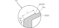
カバー3は、本実施形態においては、平面視円形状であり、膨出部31、係合部32および高摩擦部33を有している。膨出部31は、出射方向に膨出する部分である。本実施形態においては、膨出部31は、全体がドーム上に膨出している。膨出部31は、傾斜面31aを有している。傾斜面31aは、膨出部31の外周部分の表面であり、上記径方向および上記周方向、すなわちケース1の放熱部材11の搭載面11aが広がる方向に対して傾斜した面である。係合部32は、カバー3の外周端に設けられており、ケース1の放熱部材11の係合部11cと係合することにより、カバー3をケース1に取り付ける機能を果たす。
In this embodiment, the
高摩擦部33は、人間の指が触れた場合に、カバー3のその他の部分よりも高い摩擦力を発揮することが意図された部分である。ただし、ここで言う摩擦力は、物体の表面において、この表面に垂直な方向に作用する純粋な摩擦力に加えて、一方の物体の形状的な特徴(たとえば凹凸など)によって生じる力も含む概念である。高摩擦部33は、膨出部31の傾斜面31aに設けられており、本実施形態においては、上記周方向全周にわたって設けられている。
The
図1および図2に示すように、本実施形態においては、高摩擦部33は、複数のリブ34によって構成されている。図5〜図7に示すように、リブ34は、平面視において上記径方向に延びており、傾斜面31aから出射方向に起立している。リブ34の長さLは、たとえば5mm〜10mmである。リブ34の幅Wは、たとえば0.5mm〜2.0mmである。リブ34の高さHは、たとえば mmである。複数のリブ34のピッチPは、2.0mm〜4.0mmである。このようなサイズおよび配置とされた複数のリブ34は、指が触れた場合に上述した摩擦力を高める機能を果たす。このような機能を果たすためには、長さLは5mm〜20mm、幅Wは0.5mm〜2.0mm、高さHは0.5mm〜5mm、ピッチPは1.0mm〜5.0mmであることが好ましい。
As shown in FIGS. 1 and 2, in the present embodiment, the
図11は、LED照明モジュールA1を天井8に取り付ける工程を示している。天井8には、取り付け穴81が設けられており、その内部にリフレクタ82が備え付けられている。また、取り付け穴81の奥方には、給電部83が設けられている。給電部83は、IEC規格のGX53型の口金が装着可能に構成されている。取り付け穴81の下方からLED照明モジュールA1を上昇させ、取り付け穴81の奥方に位置させる。
FIG. 11 shows a process of attaching the LED lighting module A1 to the
次いで、図12に示すように、LED照明モジュールA1を給電部83に対して相対回転させる。これにより、口金14の2つのピン13が給電部83に係合する。また、絶縁部材12の凸部12aの溝部12bが給電部83に係合する。この相対回転は、平面視円形状であるLED照明モジュールA1を軸方向に延びる軸周りに回転させるものである。この際、使用者は、指をカバー3の高摩擦部33に触れさせた姿勢で、LED照明モジュールA1を回転させる。LED照明モジュールA1を給電部83に取り付けることにより、LED照明モジュールA1は、給電部83からの給電が可能であり、かつリフレクタ82に囲まれた状態となる。これにより、いわゆるダウンライトが構成される。図外のスイッチによって電源投入されると、LED照明モジュールA1のLED発光部2が点灯する。LED発光部2からの光は、カバー3を透過して一部が直接床面を照らし、他の一部がリフレクタ82によって反射されることにより、床面や壁面を照らす。
Next, as shown in FIG. 12, the LED illumination module A <b> 1 is rotated relative to the power supply unit 83. Thereby, the two
図13は、LED照明モジュールA1を天井8から取り外す工程を示している。この際、使用者は、指をカバー3の高摩擦部33に触れさせた姿勢で、LED照明モジュールA1を取り付けた際とは反対方向にLED照明モジュールA1を回転させる。これにより、口金14と給電部83との係合が解かれ、LED照明モジュールA1が取り外される。
FIG. 13 shows a process of removing the LED illumination module A1 from the
次に、LED照明モジュールA1の作用について説明する。 Next, the operation of the LED illumination module A1 will be described.
本実施形態によれば、カバー3の膨出部31の傾斜面31aに高摩擦部33が設けられている。これにより、高摩擦部33は、上記出射方向に対して完全に垂直な面に設けられているものではなく、この垂直な面に対して傾斜した構成となっている。このため、使用者が高摩擦部33に指を触れた際に、まっすぐに押し当てる格好とはならず、傾斜の分だけ高摩擦部33を介してカバー3を挟むような触れ方を取ることができる。したがって、LED照明モジュールA1を上記軸周りによりスムーズに回転させることが可能であり、給電部83への着脱をより容易に行うことができる。
According to the present embodiment, the
高摩擦部33が、上記周方向の全周に形成されていることにより、使用者は、上記周方向位置の所望の部位に指を当てて、LED照明モジュールA1を回転させることができる。
Since the
高摩擦部33が、各々が上記径方向に延びる複数のリブ34を含んでいることにより、高摩擦部33は上記周方向に沿う摩擦力をより発揮しやすい構成となっている。したがって、LED照明モジュールA1を回転させるのに適している。
Since the
リブ34の長さLを5mm〜20mmmmとすること、幅Wを、0.5mm〜2.0mmとすること、ピッチPを1.0mm〜5.0mmmmとすること、高さHを、0.5mm〜5mmとすることは、人間の指が触れた際に、上記周方向に沿った摩擦力を好適に発揮させるという利点がある。
The length L of the
LED発光部2において、複数のLEDチップ22が封止樹脂24によって覆われている構成であることにより、LED発光部2は、あたかも面発光しているような外観を呈する。これにより、LED照明モジュールA1によって照らされた物体やLED照明モジュールA1そのものが、複数の点光源に起因する明るさのばらつきが生じることを回避することができる。カバー3がLED発光部2からの光を拡散させることにより、明るさおばらつきをさらに低減することができる。
In the LED
図14〜図17は、本発明の他の実施形態を示している。なお、これらの図において、上記実施形態と同一または類似の要素には、上記実施形態と同一の符号を付している。 14 to 17 show another embodiment of the present invention. In these drawings, the same or similar elements as those in the above embodiment are denoted by the same reference numerals as those in the above embodiment.
図14は、本発明の第二実施形態に基づくLED照明モジュールを示している。図14は、LED照明モジュールA2を示す平面図である。本実施形態のLED照明モジュールA2は、高摩擦部33を構成する複数のリブ34が上述した実施形態と異なっている。本実施形態においては、複数のリブ34が2つの極大リブ35を含んでいる。
FIG. 14 shows an LED illumination module according to the second embodiment of the present invention. FIG. 14 is a plan view showing the LED illumination module A2. The LED illumination module A2 of the present embodiment is different from the above-described embodiment in that the plurality of
極大リブ35は、これ以外のリブ34よりも体積が大とされている。本実施形態においては、極大リブ35は、リブ34よりも長さLが大であり、高さHが高い。さらに、極大リブ35は、リブ34よりも幅Wが広い。なお、極大リブ35の体積をリブ34よりも大とする手法としては、長さL、高さHおよび幅Wのすべてをリブ34よりも大としてもよいし、これらのいずれかを選択的に大としてもよい。
The
2つの極大リブ35は、周方向において2つのピン13と一致する位置に設けられている。本実施形態においては、2つのピン13が周方向において180°の角度をなすように配置されている。このため、2つの極大リブ35も、周方向において180°の角度をなすように配置されている。
The two
このような実施形態によっても、給電部83への着脱をより容易に行うことが可能である。また、2つの極大リブ35によって、使用者は天井8の取り付け穴81の奥方に位置し、視認できない2つのピン13の周方向位置を容易に把握することができる。これにより、LED照明モジュールA2を給電部83に係合させる際に、2つのピン13と給電部83との位置合わせを確実に行うことが可能であり、LED照明モジュールA2の取り付けをスムーズに行うことができる。
Also according to such an embodiment, it is possible to more easily attach to and remove from the power supply unit 83. Further, the two
図15は、本発明の第三実施形態に基づくLED照明モジュールを示している。図15は、図6に示す要部拡大断面図に相当するものである。本実施形態のLED照明モジュールA3は、高摩擦部33を構成する複数のリブ34が上述した実施形態と異なっている。本実施形態においては、複数のリブ34が複数の中位リブ34bおよび最低位リブ34aを含んでいる。
FIG. 15 shows an LED illumination module according to a third embodiment of the present invention. FIG. 15 corresponds to an enlarged cross-sectional view of the main part shown in FIG. The LED illumination module A3 of the present embodiment is different from the above-described embodiment in that the plurality of
最低位リブ34aは、両隣のリブ34(中位リブ34b)よりも高さが低い。さらに、本実施形態においては、最低位リブ34aは、複数のリブ34の中で最も高さが低い。複数の中位リブ34bは、最低位リブ34aから上記周方向に離間するほど高さが高くなっている。このような構成により、複数の中位リブ34bおよび最低位リブ34aを含む領域は、これ以外の領域よりも複数の中位リブ34bおよび最低位リブ34aの上面の包絡面が凹んだ領域となっている。
The
このような実施形態によっても、給電部83への着脱をより容易に行うことが可能である。また、複数の中位リブ34bおよび最低位リブ34aによって包絡面が凹んだ領域は、使用者の指により沿いやすい形態となっている。したがって、より確実かつ容易にLED照明モジュールA3を回転させることができる。
Also according to such an embodiment, it is possible to more easily attach to and remove from the power supply unit 83. Moreover, the area | region where the envelope surface was dented by the some
図16は、本発明の第四実施形態に基づくLED照明モジュールを示している。図16は、LED照明モジュールA4を示す平面図である。本実施形態のLED照明モジュールA4は、高摩擦部33が複数の突起36によって構成されている。
FIG. 16 shows an LED lighting module according to a fourth embodiment of the present invention. FIG. 16 is a plan view showing the LED illumination module A4. In the LED illumination module A4 of the present embodiment, the
複数の突起36は、カバー3の膨出部31の傾斜面31aにおいて、周方向全周において離散的に配置されている。また、本実施形態においては、4個程度の突起36が上記径方向に沿って配列されている。
The plurality of
このような実施形態によっても、給電部83への着脱をより容易に行うことが可能である。 Also according to such an embodiment, it is possible to more easily attach to and remove from the power supply unit 83.
図17は、本発明の第五実施形態に基づくLED照明モジュールを示している。図17は、図4に示す断面図に相当する。本実施形態のLED照明モジュールA5は、カバー3の形状が上述した実施形態と異なっている。本実施形態においては、カバー3は、膨出部31を有するものの、膨出部31は、上面が平坦となっており、全体がドーム形状とはなっていない。ただし、膨出部31が周方向全周に傾斜面31aを有する点は同様である。また、この傾斜面31aに高摩擦部33が設けられている。高摩擦部33の具体的な構成は、上述したLED照明モジュールA1〜A4のいずれの構成であってもよい。
FIG. 17 shows an LED illumination module according to the fifth embodiment of the present invention. FIG. 17 corresponds to the cross-sectional view shown in FIG. The LED illumination module A5 of the present embodiment is different from the above-described embodiment in the shape of the
このような実施形態によっても、給電部83への着脱をより容易に行うことが可能である。 Also according to such an embodiment, it is possible to more easily attach to and remove from the power supply unit 83.
図18および図19は、本発明の第六実施形態に基づくLED照明モジュールを示している。本実施形態のLED照明モジュールA6は、高摩擦部33が、カバー3の周方向において互いに離間した複数のグループに分けられている点が、上述した実施形態と異なっている。
18 and 19 show an LED illumination module according to a sixth embodiment of the present invention. The LED illumination module A6 of this embodiment is different from the above-described embodiment in that the
本実施形態においては、高摩擦部33は、複数のリブ34によって構成されている。なお、高摩擦部33は、LED照明モジュールA4における複数の突起36によって構成されていてもよい。複数のリブ34は、カバー3の周方向において互いに離間した3つのグループに分けられている。これらのグループは、たとえば周方向において120°の角度を隔てて配置されている。各グループは、たとえば5つのリブ34によって構成されている。
In the present embodiment, the
このような実施形態によっても、給電部83への着脱をより容易に行うことが可能である。また、高摩擦部33の3つのグループは、LED照明モジュールA6の使用者が取り外しを行う際に、親指および人差し指と中指および薬指のいずれかとを高摩擦部33に沿わせることを促す効果が期待できる。これらお指を用いて取り外しを行うことにより、LED照明モジュールA6をより安定してより確実に回転させることができる。
Also according to such an embodiment, it is possible to more easily attach to and remove from the power supply unit 83. In addition, the three groups of the
本発明に係るLED照明モジュールは、上述した実施形態に限定されるものではない。本発明に係るLED照明モジュールの各部の具体的な構成は、種々に設計変更自在である。 The LED illumination module according to the present invention is not limited to the above-described embodiment. The specific configuration of each part of the LED lighting module according to the present invention can be varied in design in various ways.
A1〜A6 LED照明モジュール
1 ケース
11 放熱部材
11a 搭載面
11b フィン
11c 係合部
12 絶縁部材
12a 凸部
12b 溝部
13 ピン
14 口金
15 中間ブラケット
2 LED発光部
21 LED基板
21a 基材
21b 配線パターン
22 LEDチップ
23 ワイヤ
24 封止樹脂
25 堰部
26 ホルダ
26a 本体
26b 保持電極
3 カバー
31 膨出部
32 係合部
31a 傾斜面
33 高摩擦部
34 リブ
34a 最低位リブ
34b 中位リブ
35 極大リブ
36 突起
4 電源部
8 天井
81 取り付け穴
82 リフレクタ
83 給電部
A1 to A6
Claims (25)
上記LED発光部を支持するケースと、
上記LED発光部とは反対側に設けられ、給電部に対して着脱可能である口金と、
上記LED発光部からの光を透過させるカバーと、を備えたLED照明モジュールであって、
上記口金と上記給電部との着脱は、上記口金を上記給電部に対して相対回転させる動作を含んでおり、
上記カバーは、上記LED発光部の光が出射させる方向に膨出しているとともに、上記相対回転の回転軸周りの周方向に沿って設けられた高摩擦部を有することを特徴とする、LED照明モジュール。 An LED light emitting unit having one or more LED chips;
A case for supporting the LED light emitting unit;
A base that is provided on the side opposite to the LED light emitting unit and is detachable from the power feeding unit;
A LED illumination module comprising a cover that transmits light from the LED light emitting unit,
The attachment and detachment of the base and the power supply unit includes an operation of rotating the base relative to the power supply unit,
The LED illumination is characterized in that the cover bulges in a direction in which the light emitted from the LED light emitting part is emitted and has a high friction part provided along a circumferential direction around the rotation axis of the relative rotation. module.
上記複数のリブのうち上記1対のピンと周方向位置が対応するものは、体積が最大である、請求項1ないし9のいずれかに記載のLED照明モジュール。 The base includes a pair of pins,
The LED lighting module according to any one of claims 1 to 9, wherein a volume of the plurality of ribs corresponding to the pair of pins in the circumferential direction has a maximum volume.
上記LED発光部は、白色光を発する、請求項18または19に記載のLED照明モジュール。 The sealing resin is mixed with a fluorescent material that emits light different from the light from the LED chip by being excited by the light from the LED chip,
The LED lighting module according to claim 18 or 19, wherein the LED light emitting unit emits white light.
隣り合う上記LEDチップどうしが、ワイヤによって直接接続されている、請求項18ないし20のいずれかに記載のLED照明モジュール。 The plurality of LED chips is a two-wire type,
The LED lighting module according to claim 18, wherein the adjacent LED chips are directly connected by a wire.
Priority Applications (2)
| Application Number | Priority Date | Filing Date | Title |
|---|---|---|---|
| JP2014030403A JP2015156283A (en) | 2014-02-20 | 2014-02-20 | LED lighting module |
| PCT/JP2015/054154 WO2015125738A1 (en) | 2014-02-20 | 2015-02-16 | Led lighting module |
Applications Claiming Priority (1)
| Application Number | Priority Date | Filing Date | Title |
|---|---|---|---|
| JP2014030403A JP2015156283A (en) | 2014-02-20 | 2014-02-20 | LED lighting module |
Publications (2)
| Publication Number | Publication Date |
|---|---|
| JP2015156283A true JP2015156283A (en) | 2015-08-27 |
| JP2015156283A5 JP2015156283A5 (en) | 2017-02-09 |
Family
ID=53878241
Family Applications (1)
| Application Number | Title | Priority Date | Filing Date |
|---|---|---|---|
| JP2014030403A Pending JP2015156283A (en) | 2014-02-20 | 2014-02-20 | LED lighting module |
Country Status (2)
| Country | Link |
|---|---|
| JP (1) | JP2015156283A (en) |
| WO (1) | WO2015125738A1 (en) |
Citations (5)
| Publication number | Priority date | Publication date | Assignee | Title |
|---|---|---|---|---|
| JP2011044412A (en) * | 2009-08-24 | 2011-03-03 | Toshiba Lighting & Technology Corp | Lighting fixture |
| JP2011171160A (en) * | 2010-02-19 | 2011-09-01 | Toshiba Lighting & Technology Corp | Led lamp device and led lighting system |
| JP2011171190A (en) * | 2010-02-19 | 2011-09-01 | Toshiba Lighting & Technology Corp | Lighting system |
| JP2012204210A (en) * | 2011-03-25 | 2012-10-22 | Toshiba Lighting & Technology Corp | Lamp device and lighting fixture |
| JP2014143024A (en) * | 2013-01-22 | 2014-08-07 | Panasonic Corp | Illumination light source and lighting device |
-
2014
- 2014-02-20 JP JP2014030403A patent/JP2015156283A/en active Pending
-
2015
- 2015-02-16 WO PCT/JP2015/054154 patent/WO2015125738A1/en active Application Filing
Patent Citations (5)
| Publication number | Priority date | Publication date | Assignee | Title |
|---|---|---|---|---|
| JP2011044412A (en) * | 2009-08-24 | 2011-03-03 | Toshiba Lighting & Technology Corp | Lighting fixture |
| JP2011171160A (en) * | 2010-02-19 | 2011-09-01 | Toshiba Lighting & Technology Corp | Led lamp device and led lighting system |
| JP2011171190A (en) * | 2010-02-19 | 2011-09-01 | Toshiba Lighting & Technology Corp | Lighting system |
| JP2012204210A (en) * | 2011-03-25 | 2012-10-22 | Toshiba Lighting & Technology Corp | Lamp device and lighting fixture |
| JP2014143024A (en) * | 2013-01-22 | 2014-08-07 | Panasonic Corp | Illumination light source and lighting device |
Also Published As
| Publication number | Publication date |
|---|---|
| WO2015125738A1 (en) | 2015-08-27 |
Similar Documents
| Publication | Publication Date | Title |
|---|---|---|
| JP5333758B2 (en) | Lighting device and lighting fixture | |
| JP6191914B2 (en) | Lighting device | |
| TWM412319U (en) | LED illumination device | |
| JP2011134665A (en) | Lamp with base and lighting fixture | |
| JP6063301B2 (en) | Lighting device | |
| JP2010135747A (en) | Light-emitting module and lighting apparatus | |
| JP5555371B2 (en) | Light source device for illumination | |
| JP2011054340A (en) | Lighting device | |
| JP2009009870A (en) | Light source unit and compact self-ballasted lamp | |
| US8789974B2 (en) | Lighting device | |
| JP2011204444A (en) | Light emitting device and lighting equipment | |
| JP5320627B2 (en) | Lamp with lamp and lighting equipment | |
| TW201333370A (en) | Lamp and lighting device using the same | |
| JP5505672B2 (en) | Light bulb shaped lamp and lighting equipment | |
| JP2011113861A (en) | Lamp with base and lighting fixture | |
| WO2015125738A1 (en) | Led lighting module | |
| JP6212196B2 (en) | Lighting device | |
| JP5824680B2 (en) | Lamp and lighting device | |
| JP2013115005A (en) | Lighting apparatus | |
| JP6191813B2 (en) | Illumination light source and illumination device | |
| JP2013182857A (en) | Lighting device | |
| JP5822068B2 (en) | Lighting device | |
| WO2019207932A1 (en) | Lighting device | |
| JP2016167458A (en) | Luminaire | |
| JP5963014B2 (en) | lighting equipment |
Legal Events
| Date | Code | Title | Description |
|---|---|---|---|
| A711 | Notification of change in applicant |
Free format text: JAPANESE INTERMEDIATE CODE: A712 Effective date: 20161118 |
|
| A521 | Request for written amendment filed |
Free format text: JAPANESE INTERMEDIATE CODE: A523 Effective date: 20161217 |
|
| A621 | Written request for application examination |
Free format text: JAPANESE INTERMEDIATE CODE: A621 Effective date: 20161217 |
|
| A131 | Notification of reasons for refusal |
Free format text: JAPANESE INTERMEDIATE CODE: A131 Effective date: 20171205 |
|
| A02 | Decision of refusal |
Free format text: JAPANESE INTERMEDIATE CODE: A02 Effective date: 20180605 |