JP2015134591A - Electronic device, control method for connection of portable terminal, and electric power control program - Google Patents
Electronic device, control method for connection of portable terminal, and electric power control program Download PDFInfo
- Publication number
- JP2015134591A JP2015134591A JP2014007558A JP2014007558A JP2015134591A JP 2015134591 A JP2015134591 A JP 2015134591A JP 2014007558 A JP2014007558 A JP 2014007558A JP 2014007558 A JP2014007558 A JP 2014007558A JP 2015134591 A JP2015134591 A JP 2015134591A
- Authority
- JP
- Japan
- Prior art keywords
- connection
- connection port
- monitoring
- electronic device
- mobile terminal
- Prior art date
- Legal status (The legal status is an assumption and is not a legal conclusion. Google has not performed a legal analysis and makes no representation as to the accuracy of the status listed.)
- Pending
Links
Images


Classifications
-
- B—PERFORMING OPERATIONS; TRANSPORTING
- B60—VEHICLES IN GENERAL
- B60L—PROPULSION OF ELECTRICALLY-PROPELLED VEHICLES; SUPPLYING ELECTRIC POWER FOR AUXILIARY EQUIPMENT OF ELECTRICALLY-PROPELLED VEHICLES; ELECTRODYNAMIC BRAKE SYSTEMS FOR VEHICLES IN GENERAL; MAGNETIC SUSPENSION OR LEVITATION FOR VEHICLES; MONITORING OPERATING VARIABLES OF ELECTRICALLY-PROPELLED VEHICLES; ELECTRIC SAFETY DEVICES FOR ELECTRICALLY-PROPELLED VEHICLES
- B60L58/00—Methods or circuit arrangements for monitoring or controlling batteries or fuel cells, specially adapted for electric vehicles
- B60L58/10—Methods or circuit arrangements for monitoring or controlling batteries or fuel cells, specially adapted for electric vehicles for monitoring or controlling batteries
- B60L58/12—Methods or circuit arrangements for monitoring or controlling batteries or fuel cells, specially adapted for electric vehicles for monitoring or controlling batteries responding to state of charge [SoC]
-
- B—PERFORMING OPERATIONS; TRANSPORTING
- B60—VEHICLES IN GENERAL
- B60L—PROPULSION OF ELECTRICALLY-PROPELLED VEHICLES; SUPPLYING ELECTRIC POWER FOR AUXILIARY EQUIPMENT OF ELECTRICALLY-PROPELLED VEHICLES; ELECTRODYNAMIC BRAKE SYSTEMS FOR VEHICLES IN GENERAL; MAGNETIC SUSPENSION OR LEVITATION FOR VEHICLES; MONITORING OPERATING VARIABLES OF ELECTRICALLY-PROPELLED VEHICLES; ELECTRIC SAFETY DEVICES FOR ELECTRICALLY-PROPELLED VEHICLES
- B60L1/00—Supplying electric power to auxiliary equipment of vehicles
- B60L1/006—Supplying electric power to auxiliary equipment of vehicles to power outlets
-
- B—PERFORMING OPERATIONS; TRANSPORTING
- B60—VEHICLES IN GENERAL
- B60R—VEHICLES, VEHICLE FITTINGS, OR VEHICLE PARTS, NOT OTHERWISE PROVIDED FOR
- B60R16/00—Electric or fluid circuits specially adapted for vehicles and not otherwise provided for; Arrangement of elements of electric or fluid circuits specially adapted for vehicles and not otherwise provided for
- B60R16/02—Electric or fluid circuits specially adapted for vehicles and not otherwise provided for; Arrangement of elements of electric or fluid circuits specially adapted for vehicles and not otherwise provided for electric constitutive elements
- B60R16/03—Electric or fluid circuits specially adapted for vehicles and not otherwise provided for; Arrangement of elements of electric or fluid circuits specially adapted for vehicles and not otherwise provided for electric constitutive elements for supply of electrical power to vehicle subsystems or for
- B60R16/033—Electric or fluid circuits specially adapted for vehicles and not otherwise provided for; Arrangement of elements of electric or fluid circuits specially adapted for vehicles and not otherwise provided for electric constitutive elements for supply of electrical power to vehicle subsystems or for characterised by the use of electrical cells or batteries
-
- B—PERFORMING OPERATIONS; TRANSPORTING
- B60—VEHICLES IN GENERAL
- B60W—CONJOINT CONTROL OF VEHICLE SUB-UNITS OF DIFFERENT TYPE OR DIFFERENT FUNCTION; CONTROL SYSTEMS SPECIALLY ADAPTED FOR HYBRID VEHICLES; ROAD VEHICLE DRIVE CONTROL SYSTEMS FOR PURPOSES NOT RELATED TO THE CONTROL OF A PARTICULAR SUB-UNIT
- B60W10/00—Conjoint control of vehicle sub-units of different type or different function
- B60W10/24—Conjoint control of vehicle sub-units of different type or different function including control of energy storage means
- B60W10/26—Conjoint control of vehicle sub-units of different type or different function including control of energy storage means for electrical energy, e.g. batteries or capacitors
-
- H—ELECTRICITY
- H04—ELECTRIC COMMUNICATION TECHNIQUE
- H04L—TRANSMISSION OF DIGITAL INFORMATION, e.g. TELEGRAPHIC COMMUNICATION
- H04L67/00—Network arrangements or protocols for supporting network services or applications
- H04L67/01—Protocols
- H04L67/12—Protocols specially adapted for proprietary or special-purpose networking environments, e.g. medical networks, sensor networks, networks in vehicles or remote metering networks
-
- H—ELECTRICITY
- H04—ELECTRIC COMMUNICATION TECHNIQUE
- H04W—WIRELESS COMMUNICATION NETWORKS
- H04W52/00—Power management, e.g. TPC [Transmission Power Control], power saving or power classes
- H04W52/02—Power saving arrangements
- H04W52/0209—Power saving arrangements in terminal devices
- H04W52/0261—Power saving arrangements in terminal devices managing power supply demand, e.g. depending on battery level
- H04W52/0296—Power saving arrangements in terminal devices managing power supply demand, e.g. depending on battery level switching to a backup power supply
-
- Y—GENERAL TAGGING OF NEW TECHNOLOGICAL DEVELOPMENTS; GENERAL TAGGING OF CROSS-SECTIONAL TECHNOLOGIES SPANNING OVER SEVERAL SECTIONS OF THE IPC; TECHNICAL SUBJECTS COVERED BY FORMER USPC CROSS-REFERENCE ART COLLECTIONS [XRACs] AND DIGESTS
- Y02—TECHNOLOGIES OR APPLICATIONS FOR MITIGATION OR ADAPTATION AGAINST CLIMATE CHANGE
- Y02D—CLIMATE CHANGE MITIGATION TECHNOLOGIES IN INFORMATION AND COMMUNICATION TECHNOLOGIES [ICT], I.E. INFORMATION AND COMMUNICATION TECHNOLOGIES AIMING AT THE REDUCTION OF THEIR OWN ENERGY USE
- Y02D30/00—Reducing energy consumption in communication networks
- Y02D30/70—Reducing energy consumption in communication networks in wireless communication networks
-
- Y—GENERAL TAGGING OF NEW TECHNOLOGICAL DEVELOPMENTS; GENERAL TAGGING OF CROSS-SECTIONAL TECHNOLOGIES SPANNING OVER SEVERAL SECTIONS OF THE IPC; TECHNICAL SUBJECTS COVERED BY FORMER USPC CROSS-REFERENCE ART COLLECTIONS [XRACs] AND DIGESTS
- Y02—TECHNOLOGIES OR APPLICATIONS FOR MITIGATION OR ADAPTATION AGAINST CLIMATE CHANGE
- Y02T—CLIMATE CHANGE MITIGATION TECHNOLOGIES RELATED TO TRANSPORTATION
- Y02T10/00—Road transport of goods or passengers
- Y02T10/60—Other road transportation technologies with climate change mitigation effect
- Y02T10/70—Energy storage systems for electromobility, e.g. batteries
Abstract
Description
本発明は、複数の携帯端末を接続可能な車載装置に関し、特に、アイドリングストップ等のエンジン制御を行う車両に搭載される車載装置に関する。 The present invention relates to a vehicle-mounted device to which a plurality of portable terminals can be connected, and particularly to a vehicle-mounted device mounted on a vehicle that performs engine control such as idling stop.
排出ガスの低減や燃料の節約を図るために、アイドリング時にエンジンを停止させるエンジン制御を行う車両が普及しつつある。例えば、自動車が交差点で信号待ちをしている間、エンジンを自動的に停止し、その後、信号が切替わったとき、エンジンを自動的に再始動させるようなエンジン制御が行われている。 In order to reduce exhaust gas and save fuel, vehicles that perform engine control that stops the engine during idling are becoming popular. For example, engine control is performed so that the engine is automatically stopped while a car is waiting for a signal at an intersection, and then the engine is automatically restarted when the signal is switched.
特許文献1は、エンジン自動停止中の消費電力を大幅に抑制し、エンジン自動運転の長期化を図ることができ、複数の電装品による消費電力を一律に抑制し、特定の電装品の機能が著しく損なわれることのないエンジンの自動停止・自動再始動装置を開示している。 Patent Document 1 significantly suppresses the power consumption during automatic engine stop, and can extend the engine automatic operation for a long time, uniformly suppresses the power consumption by a plurality of electrical components, and functions of specific electrical components Disclosed is an automatic engine stop / restart system that is not significantly damaged.
特許文献2は、供給可能電流値算出手段によりバッテリーが供給できる供給可能電流値を正確に算出し、この正確な供給可能電流値に基づき、エコラン制御手段と、給電制限手段とを制御する車両制御装置を開示している。 Japanese Patent Application Laid-Open No. 2004-228688 accurately calculates a suppliable current value that can be supplied by a battery by a suppliable current value calculating means, and controls the eco-run control means and the power supply restricting means based on the accurate suppliable current value. An apparatus is disclosed.
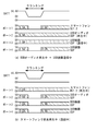
アイドリング停止車両のようなエンジンの停止および再始動を行う車両には、バッテリーが搭載されており、エンジンを再始動させるとき、バッテリーの電力を利用してクランキングを行うためにモータを始動させる。モータの始動時には、比較的大きな電力が消費されるため、バッテリーから供給される電圧が一時的に低下する。図9(a)は、エンジン再始動時のバッテリーの供給電圧Vpの変化を示すグラフである。エンジンが停止されているとき、あるいはエンジンが始動されている定常状態にあるとき、バッテリーの供給電圧Vpは、例えば、約14.4Vで一定である。停止したエンジンを再始動させるとき、上記したようにモータの始動により、供給電圧Vpが約4Vに低下する。その後、エンジンが始動されると、供給電圧Vpは、14.4Vの元の電圧に戻る。以後、時間t1〜t2のエンジンを再始動させる期間をクランキングと呼ぶ。 A vehicle that stops and restarts an engine such as an idling stop vehicle is equipped with a battery, and when the engine is restarted, a motor is started to perform cranking using electric power of the battery. When starting the motor, a relatively large amount of electric power is consumed, so that the voltage supplied from the battery temporarily decreases. FIG. 9A is a graph showing changes in the battery supply voltage Vp when the engine is restarted. When the engine is stopped or in a steady state where the engine is started, the battery supply voltage Vp is constant at about 14.4V, for example. When the stopped engine is restarted, the supply voltage Vp is reduced to about 4 V by starting the motor as described above. Thereafter, when the engine is started, the supply voltage Vp returns to the original voltage of 14.4V. Hereinafter, a period during which the engine is restarted at time t1 to t2 is referred to as cranking.
クランキング時に、供給電圧Vpが車載装置の動作電圧を下回ると、車載装置が一時的に動作不能になってしまう。そこで、図9(b)に示すように昇圧電源を用いてバッテリーからの供給電圧Vpを昇圧し、各機器が正常に動作するよう対策が取られている。例えば、6Vに昇圧された電圧は、USB接続等のVBUSの電力として供給される。これにより、例えば、クランキング時に、USB接続された携帯端末を利用した音声を音切れを生じさせることなく再生することができる。 If the supply voltage Vp falls below the operating voltage of the in-vehicle device at the time of cranking, the in-vehicle device temporarily becomes inoperable. Therefore, as shown in FIG. 9B, measures are taken to boost the supply voltage Vp from the battery using a boost power source so that each device operates normally. For example, the voltage boosted to 6V is supplied as VBUS power for USB connection or the like. Thereby, for example, at the time of cranking, it is possible to reproduce sound using a USB-connected portable terminal without causing sound interruption.
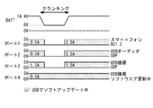
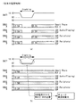
しかしながら、近年、車載装置には、急速充電可能なポートを含む多数のUSBポートが採用され、接続ポートの全体で必要とされる消費電力が増大している。そこで、車載装置は、図10(a)に示すように、クランキング時にUSBポートへの電源供給を遮断することで、USB接続を介しての電力消費をバッテリーの許容電力以下に抑える接続制御も可能であるが、そうすると、使用中の携帯端末の動作が一時的に遮断されてしまう。例えば、USBオーディオのような携帯端末を利用して音楽再生を行っている場合やハンズフリー通話を行っている場合に、一時的な音切れが発生してしまい、ユーザーに不快感を与えてしまう。あるいは、USBメモリにより車載装置のソフトウエアのアップデートを行っている場合に、アップデートが失敗し、再度、アップデートしなければならないような不具合が生じてしまう。 However, in recent years, in-vehicle devices have adopted a large number of USB ports including ports that can be rapidly charged, and the power consumption required for the entire connection port has increased. Therefore, as shown in FIG. 10A, the in-vehicle device also performs connection control that suppresses the power consumption through the USB connection to less than the allowable power of the battery by cutting off the power supply to the USB port during cranking. Although it is possible, if it does so, operation | movement of the portable terminal in use will be interrupted | blocked temporarily. For example, when music is played using a portable terminal such as USB audio or when a hands-free call is made, temporary sound interruption may occur, causing discomfort to the user. . Or, when the software of the in-vehicle device is updated by the USB memory, the update fails and a problem arises that the update must be performed again.
一方、図10(b)に示すように、クランキング期間中にすべてのUSB接続への電力を補償しようとすれば、それに対応できるように昇圧電源のチョークコイルの電流容量を増やす必要がある。この場合には、昇圧電源の大型化の他に、車載装置または車内の電装配線のヒューズが切れてしまうという問題がある。 On the other hand, as shown in FIG. 10B, if the power to all the USB connections is to be compensated during the cranking period, it is necessary to increase the current capacity of the choke coil of the boost power supply so as to cope with it. In this case, in addition to increasing the size of the boosting power source, there is a problem that the fuse of the in-vehicle device or the electrical wiring in the vehicle is blown.
本発明は、上記のような従来の課題を解決するものであり、バッテリーから供給される電圧が低下したとき、使用中の携帯端末の動作を継続可能な電子装置、携帯端末の接続制御方法、および電力制御プログラムを提供することを目的とする。 The present invention solves the conventional problems as described above, and when the voltage supplied from the battery drops, an electronic device capable of continuing the operation of the mobile terminal in use, a connection control method for the mobile terminal, And it aims at providing a power control program.
本発明に係る電子装置は、車両に搭載されたバッテリーから供給される電力によって動作可能なものであって、複数の携帯端末を接続可能であり、かつバッテリーからの電力を供給可能な接続手段と、前記接続手段により接続された携帯端末の使用状況を監視する監視手段と、前記バッテリーからの供給電圧がしきい値以下であるか否かを検出する検出手段と、前記検出手段により供給電圧がしきい値以下であることが検出されたとき、前記監視手段の監視結果に基づき前記接続手段を介しての携帯端末への電力供給を制御する制御手段とを有する。 An electronic device according to the present invention is operable by electric power supplied from a battery mounted on a vehicle, and can be connected to a plurality of portable terminals, and can be connected to a connecting means capable of supplying electric power from the battery. Monitoring means for monitoring the usage status of the mobile terminal connected by the connection means; detection means for detecting whether the supply voltage from the battery is below a threshold; and the supply voltage by the detection means Control means for controlling power supply to the portable terminal via the connection means based on a monitoring result of the monitoring means when it is detected that the value is equal to or less than a threshold value.
好ましくは前記接続手段は、複数の接続ポートを含み、前記制御手段は、監視手段の監視結果に基づき切断不可能な接続ポートを判別し、当該切断不可能な接続ポートへの電力供給を継続する。好ましくは前記接続手段は、複数の接続ポートを含み、前記制御手段は、監視手段の監視結果に基づき切断可能な接続ポートを判別し、当該切断可能な接続ポートへの電力供給を遮断する。好ましくは前記監視手段は、電子装置によって実行されている機能を監視し、前記制御手段は、実行されている機能に基づき接続ポートが切断可能な否かを判別する。好ましくは前記監視手段は、電子装置に搭載されているアプリケーションが実行されているか否かにより機能を監視する。好ましくは前記制御手段は、監視手段による監視結果に基づき、携帯端末との接続により音楽データに基づき音楽を再生しているとき、携帯端末との接続により通話がされているとき、および携帯端末との接続によりソフトウエアの更新が行われているとき、当該携帯端末が接続されている接続ポートは切断不可能であると判別する。好ましくは前記制御手段は、前記監視結果に基づき予め決められた接続ポートへの電力供給を遮断する。好ましくは前記接続手段は、電力供給量を異にする複数種別の接続ポートを含み、前記制御手段は、接続ポートの種別に基づき切断可能な接続ポートを判別する。好ましくは前記制御手段は、バッテリーの供給電圧がしきい値以下のときの許容可能な電力量に基づき切断可能な接続ポートを判別する。好ましくは前記検出手段は、前記バッテリーからの供給電圧とイグニションのステータス情報とに基づきエンジンのクランキング期間を検出し、当該検出結果を前記制御手段へ提供する。好ましくは前記接続ポートは、携帯端末へ電力を供給するための電源ラインと、電源ラインと電源との間に接続されたスイッチとを含み、前記スイッチは、前記制御手段からの制御信号に応答して開閉される。前記接続ポートは、例えばUSB接続ポートである。 Preferably, the connection unit includes a plurality of connection ports, and the control unit determines a connection port that cannot be disconnected based on a monitoring result of the monitoring unit, and continues power supply to the connection port that cannot be disconnected. . Preferably, the connection unit includes a plurality of connection ports, and the control unit determines a connection port that can be disconnected based on a monitoring result of the monitoring unit, and cuts off power supply to the connection port that can be disconnected. Preferably, the monitoring unit monitors a function being executed by the electronic device, and the control unit determines whether or not the connection port can be disconnected based on the function being executed. Preferably, the monitoring means monitors the function depending on whether or not an application installed in the electronic device is being executed. Preferably, the control means is based on a monitoring result by the monitoring means, when playing music based on music data by connection with a portable terminal, when a call is made by connection with the portable terminal, and with the portable terminal When the software is updated through the connection, it is determined that the connection port to which the mobile terminal is connected cannot be disconnected. Preferably, the control means cuts off the power supply to the connection port determined in advance based on the monitoring result. Preferably, the connection unit includes a plurality of types of connection ports having different power supply amounts, and the control unit determines a connection port that can be disconnected based on a type of the connection port. Preferably, the control means discriminates a connection port that can be disconnected based on an allowable power amount when a supply voltage of the battery is equal to or lower than a threshold value. Preferably, the detection means detects a cranking period of the engine based on a supply voltage from the battery and ignition status information, and provides the detection result to the control means. Preferably, the connection port includes a power supply line for supplying power to the portable terminal, and a switch connected between the power supply line and the power supply, and the switch is responsive to a control signal from the control means. Open and close. The connection port is, for example, a USB connection port.
本発明に係る電子装置における携帯端末の接続制御方法は、車両に搭載されたバッテリーから供給される電力によって動作可能な電子装置であって、当該電子装置の複数の接続ポートを介して複数の携帯端末が接続可能な電子装置において成されるものであって、前記接続ポートを介して接続された携帯端末の使用状況を監視する監視ステップと、前記バッテリーからの供給電圧がしきい値以下であるか否かを検出する検出ステップと、前記検出ステップにより供給電圧がしきい値以下であることが検出されたとき、前記監視ステップの監視結果に基づき前記接続ポートを介しての携帯端末への電力供給を制御する制御ステップとを有する。 A connection control method for a portable terminal in an electronic device according to the present invention is an electronic device that can be operated by electric power supplied from a battery mounted on a vehicle, and a plurality of portable devices via a plurality of connection ports of the electronic device. A monitoring step for monitoring a use status of a mobile terminal connected via the connection port, and a supply voltage from the battery is equal to or lower than a threshold value, which is formed in an electronic device to which the terminal can be connected A detection step for detecting whether or not, and when the detection step detects that the supply voltage is less than or equal to a threshold value, power to the mobile terminal via the connection port based on the monitoring result of the monitoring step And a control step for controlling the supply.
本発明に係る電力制御プログラムは、車両に搭載されたバッテリーから供給される電力によって動作可能な電子装置であって、当該電子装置の複数の接続ポートを介して複数の携帯端末が接続可能な電子装置が実行するものであって、前記接続ポートを介して接続された携帯端末の使用状況を監視する監視ステップと、前記バッテリーからの供給電圧がしきい値以下であるか否かを検出する検出ステップと、前記検出ステップにより供給電圧がしきい値以下であることが検出されたとき、前記監視ステップの監視結果に基づき前記接続ポートを介しての携帯端末への電力供給を制御する制御ステップとを有する。 An electric power control program according to the present invention is an electronic device that can be operated by electric power supplied from a battery mounted on a vehicle, and can be connected to a plurality of portable terminals via a plurality of connection ports of the electronic device. A monitoring step that is executed by the device and that monitors the usage status of the mobile terminal connected via the connection port, and detection that detects whether or not the supply voltage from the battery is below a threshold value And a control step for controlling power supply to the portable terminal via the connection port based on a monitoring result of the monitoring step when the detection step detects that the supply voltage is equal to or lower than a threshold value. Have
本発明によれば、バッテリーから供給される電圧がしきい値以下に低下したような場合に、接続されている携帯端末の使用状況に応じて携帯端末への電源供給を制御するようにしたので、バッテリーからの許容可能な電力の範囲内で携帯端末の使用を継続させることができる。例えば、アイドリングストップの車両では、エンジン始動時のクランキングによりバッテリーからの電圧が一時的に低下するが、この間、携帯端末を利用した音楽再生の音切れなどを防止することができる。 According to the present invention, when the voltage supplied from the battery drops below the threshold value, the power supply to the mobile terminal is controlled according to the usage status of the connected mobile terminal. In addition, the use of the portable terminal can be continued within the allowable power range from the battery. For example, in an idling stop vehicle, the voltage from the battery temporarily decreases due to cranking when the engine is started. During this time, it is possible to prevent the sound from being interrupted by music playback using a portable terminal.
次に、本発明の実施の形態について図面を参照して説明する。本発明の好ましい実施の形態は、車内に持ち込まれた携帯端末を接続可能な車載装置を含む、携帯端末接続システムを例示する。携帯端末は、車載装置に接続して利用可能なポータブルの端末であり、例えば、スマートフォン、タブレット端末、携帯電話、携帯型音楽プレーヤー、携帯型ゲーム機、アップデート用端末、交通情報取得モジュールなどである。携帯端末は、通信機能、データ保持機能や情報処理機能を備え、外部ネットワークと接続したり、音声通話をしたり、オーディオデータやビデオデータを記憶したり、搭載したアプリケーションにより種々の機能を実行することができる。また、携帯端末は、それ自身が充電機能を備えているものであってもよいし、外部から電力供給を受けて動作するもののいずれであってもよい。 Next, embodiments of the present invention will be described with reference to the drawings. A preferred embodiment of the present invention exemplifies a portable terminal connection system including an in-vehicle device capable of connecting a portable terminal brought into the vehicle. The portable terminal is a portable terminal that can be used by connecting to an in-vehicle device, such as a smartphone, a tablet terminal, a mobile phone, a portable music player, a portable game machine, an update terminal, a traffic information acquisition module, and the like. . The portable terminal has a communication function, a data holding function, and an information processing function, and connects to an external network, makes a voice call, stores audio data and video data, and executes various functions depending on installed applications. be able to. Moreover, the mobile terminal itself may be provided with a charging function, or may be any one that operates by receiving power supply from the outside.
一方、車載装置は、車両に搭載される電子装置であって、オーディオ/ビデオ再生機能、テレビ/ラジオ放送受信機能、ナビゲーション機能などを含むことができる。車載装置と携帯端末とは、USBなどの接続ポートを介して接続することができ、相互に必要なデータの送受を行うことができる。好ましい態様では、接続ポートは、接続する携帯端末を充電する充電接続の機能を持ち、BC1.2、SDP、CDPなど各種充電方式の規格に対応する。また、車載装置は、接続された携帯端末と情報を共有したり、連携して動作することができ、携帯端末から出力される音声信号や映像信号を、接続ポートを介して受け取り、これらを車載ディスプレイや車載スピーカから出力することができる。また、車載装置は、接続ポートを介して携帯端末を操作することができ、携帯端末が保有するアプリケーションを実行し、帯端末から音声信号や映像信号を受信することができる。さらに、車載装置は、接続される携帯端末に着信があったとき、いわゆるハンズフリー通話をサポートする。 On the other hand, the in-vehicle device is an electronic device mounted on a vehicle and can include an audio / video playback function, a television / radio broadcast reception function, a navigation function, and the like. The in-vehicle device and the portable terminal can be connected via a connection port such as a USB, and necessary data can be transmitted and received. In a preferred embodiment, the connection port has a charging connection function for charging the mobile terminal to be connected, and corresponds to various charging system standards such as BC1.2, SDP, and CDP. The in-vehicle device can share information with the connected mobile terminal or operate in cooperation, receives audio signals and video signals output from the mobile terminal via the connection port, and receives these in-vehicle It can be output from a display or a vehicle-mounted speaker. The in-vehicle device can operate the portable terminal via the connection port, can execute an application held by the portable terminal, and can receive an audio signal and a video signal from the band terminal. Further, the in-vehicle device supports a so-called hands-free call when an incoming call is received at the connected mobile terminal.
さらに好ましい態様では、車載装置は、アイドリング時にエンジンの自動停止を行い、バッテリーからの供給電圧を利用してエンジンの再始動を行うようなアイドリングストップ車両に搭載され、車載装置は、そのようなバッテリーから供給電圧により動作される。 In a further preferred aspect, the in-vehicle device is mounted on an idling stop vehicle that automatically stops the engine during idling and restarts the engine using a supply voltage from the battery. It is operated by the supply voltage.
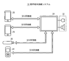
図1は、本発明の実施例に係る携帯端末接続システムの構成を示す図である。同図において、携帯端末接続システム10は、複数の携帯端末20と、これら携帯端末20が接続された車載装置30とを含んで構成される。ここでは、携帯端末20は、通信機能を備えた多機能型のスマートフォン、アップデート用端末、携帯型音楽プレーヤー等である。車載装置30は、ナビゲーション機能やマルチメディア機能、また接続された携帯端末20を充電する充電機能を備え、さらにハンズフリー通話セット32を備える。
FIG. 1 is a diagram illustrating a configuration of a mobile terminal connection system according to an embodiment of the present invention. In the figure, the mobile terminal connection system 10 includes a plurality of
携帯端末20はそれぞれ、USB(Universal Serial Bus)接続50により車載装置30と通信接続、充電接続が可能である。また、携帯端末20および車載装置30は、USB接続50に対応するため、USBケーブルのコネクタを接続することができる。携帯端末20と車載装置30とがUSBケーブルにより相互に接続されると、USBプラグ・アンド・プレイにより相互に機器が認識される。また、USB接続50が有効であるとき、携帯端末20は、車載装置30からの電力供給を受けることができ、バッテリーの充電が可能となる。
Each of the
図2は、携帯端末の典型的な構成を示すブロック図である。携帯端末20は、ユーザーからの入力を受け取る入力部100、USB接続50により車載装置30との接続を可能にする接続部110、ディスプレイに種々の画像を表示する表示部120、音声を出力する音声出力部130、外部のネットワークとのデータ通信、および公衆無線回線網を介しての電話機との通話等を可能にする通信部140、制御部150、アプリケーションソフトやプログラム等を格納するプログラムメモリ160、オーディオデータ、ビデオデータ、地図データなどを記憶するデータメモリ170、各部を接続するバス180とを備えている。
FIG. 2 is a block diagram showing a typical configuration of the mobile terminal. The
プログラムメモリ160には、例えば、オーディオデータやビデオデータを再生するアプリケーション、ゲームを実行するアプリケーション、音声通話を行うためのプログラム、通信部140を介してインターネット上の情報をブラウズするためのプログラムなどが格納される。さらにプログラムメモリ160には、携帯端末20と車載装置30とがUSB接続50により接続されているとき、両装置は、拡張動作モードで動作させるため拡張プログラムを含む。拡張動作モードでは、拡張プログラムは、車載装置30から送信されたコマンドを解読し、当該コマンドにより各部を制御する。例えば、車載装置側から携帯端末側の音楽再生用のアプリケーションを起動し、当該アプリケーションにより再生された音声信号がオーディオ接続44を介して車載装置30へ送信される。
The
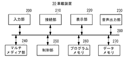
図3は、車載装置30の典型的な構成を示すブロック図である。同図に示すように、車載装置30は、ユーザーからの入力を受け取る入力部200、USB接続50により携帯端末20との接続を可能にする接続部210、表示部220、音声を出力する音声出力部230、種々のメディアの再生等を実行するマルチメディア部240、制御部250、アプリケーション等を実行するためのプログラムを格納するプログラムメモリ260、オーディオデータ、ビデオデータ、地図データなどのデータを記憶するデータメモリ270、各部を接続するバス280とを備えている。
FIG. 3 is a block diagram showing a typical configuration of the in-
接続部210は、USB接続50のための複数の接続ポートを含む。本実施例の接続ポート210は、後述するように、クランキング時の電力制御を可能にするため、バッテリーからの電源と、USB接続の電源供給ラインとの間にスイッチを含むことができる。スイッチは、制御部250からの制御信号に応答して開閉し、USB接続の電力を制御する。
The
マルチメディア部240は、CD、DVD、ブルーレイディスク、メモリ媒体、接続された携帯端末20、データメモリ270などに記録されたオーディオデータやビデオデータを再生する機能、テレビ放送やラジオ放送を受信する機能などを有する。プログラムメモリ260には、ナビゲーション機能を実行するアプリケーションやマルチメディア部240を制御するプログラムに加え、携帯端末20と接続されたときの拡張動作モードを制御するプログラムなどが記憶される。なお、車載装置30は、ナビゲーション動作に必要なGPS測位情報、車速情報、方位情報などを受け取ることができる。
The
制御部250は、好ましい態様では、ROM、RAMなどを含むマイクロコントローラから構成され、ROMまたはRAMは、車載装置の各部の動作を制御するための種々のプログラムを格納することができる。本実施例の制御部118は、車両に搭載されたバッテリーからの供給電圧に基づき、接続された携帯端末への電力供給を制御する携帯端末接続プログラムを保持する。
In a preferred embodiment, the
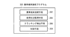
図4に、本実施例に係る携帯端末接続プログラムの構成を示す図である。携帯端末接続プログラム300は、クランキング時における消費電力を抑制するため、接続された携帯端末の電力供給を制御するプログラムであり、制御部250によって実行される。携帯端末接続プログラム300は、複数の携帯端末20を接続し、バッテリーまたはUSB接続から供給される電力により動作を可能にする携帯端末接続手段302と、接続された携帯端末20の使用状況を監視する使用状況監視手段304と、バッテリーから供給される電圧およびイグニッションキーの状態に基づきクランキングを検出するクランキング検出手段306と、クランキングが検出されたとき、使用状況監視手段304による監視情報に基づき、携帯端末接続手段302による電力供給を制御する制御手段308とを備えている。
FIG. 4 is a diagram illustrating a configuration of the mobile terminal connection program according to the present embodiment. The mobile terminal connection program 300 is a program for controlling the power supply of the connected mobile terminal in order to suppress power consumption during cranking, and is executed by the
携帯端末接続手段302は、例えば、USBなどの複数の接続ポートに繋がれた携帯端末を電気的に接続することができる。これにより、携帯端末20は、車載装置30に通信接続され、車載装置30が各携帯端末と通信を行うことができ、車載装置側から携帯端末を操作したり、各機能やデータを共有することができる。また、携帯端末20は、車載装置30に充電接続され、接続された携帯端末は車載装置30を介して充電される。
The mobile
使用状況監視手段304は、携帯端末の接続の有無をチェックし、かつ接続された携帯端末の使用状況を監視することができる。また、使用状況監視手段304は、監視結果を表した監視情報を逐次作成し、これを制御手段308へ提供することができる。例えば、スマートフォンが接続されている場合、通信状況監視手段304は、車載装置に搭載されたオペレーティングシステムまたはアプリケーションソフトウエアの動作状態に基づき携帯端末20のハンズフリー通話、音楽再生、不使用状態などの使用状況を監視することができる。また、使用状況監視手段304は、接続ポートから携帯端末へ供給される電流を監視することができるのであれば、当該供給電流に基づき携帯端末の使用状況を監視してもよい。使用状況監視手段304は、これ以外にも、アップデート用携帯端末によるソフトウエアのアップデートや、交通情報取得モジュールによる通信などの使用状況を監視することができる。
The usage
図5は、使用状況監視手段により作成される監視情報を例示する図である。監視情報には、例えば、車載装置に設置された各接続ポート(ポートの種別)に応じて、使用状況監視手段304の監視結果による各携帯端末の使用状況が書き込まれる。使用状況に関する情報は、携帯端末の使用状況の変化に応じて適宜更新される。
FIG. 5 is a diagram illustrating the monitoring information created by the usage status monitoring unit. In the monitoring information, for example, according to each connection port (port type) installed in the in-vehicle device, the usage status of each mobile terminal based on the monitoring result of the usage
クランキング検出手段306は、バッテリーからの供給電力がしきい値以下であるか否かによりクランキングを検出する。さらに好ましい態様では、クランキング検出手段206は、イグニションスイッチからステータス(状態)情報を取得し、例えば、イグニションスイッチがオン状態で、かつ、バッテリーの供給電圧がしきい値以下であるときにクランキングであることを検出してもよい。CDP(Charging Downstream Port)は、1.5AをサポートするアクティブUSB2.0データ通信であり、SDP(Standard Downstream Port)は、500mAをサポートするアクティブUSB2.0データ通信)であり、BC1.2は、バッテリー充電の仕様(USB Battery Charging Specification Revision1.2である。これらの種別は一例である。
The cranking
制御手段308は、クランキング検出手段306によりクランキングが検出されたとき、使用状況監視手段304により作成された監視情報に基づき、携帯端末への電力供給をクランキング期間中制御することができる。例えば、クランキング時に、接続されたスマートフォンがハンズフリー通話や音楽再生に利用されている場合、制御手段308は、使用中である接続ポートへの電力供給を維持するが、不使用と判別された接続ポートへの電力供給を一時的に遮断することができる。制御手段308は、監視情報に基づき切断可能な接続ポートを判別するが、要は、クランキング時にバッテリーからUSBポートへ許容可能な電力を下回るように切断可能な接続ポートを判別する。判別するためのアルゴリズムは種々あるが、例えば、上記したように使用中の接続ポートを除き、それ以外の接続ポートへの電力供給を遮断したり、あるいは、使用中の接続ポートと切断する接続ポートとの関係を予め判別テーブルに記憶させておきそれに従い切断する接続ポートを判別する。さらに切断可能な判別ポートに予め優先順位を付しておき、上記許容可能な電力を越えない範囲で、不使用の接続ポートの接続を維持させるようにしてもよい。この場合、不使用であっても、充電中の接続ポートの接続を優先させるようにしてもよい。制御手段308は、切断可能と判別された接続ポートのスイッチを開かせるための制御信号を接続部210へ提供する。
When the cranking
図6A及び図6Bは、本実施例における車載装置の接続制御例を示す図である。例えば、接続ポート2でUSBオーディオが音楽再生中であり、かつ、接続ポート3でUSB機器が通信中であった場合、制御手段308は、図6A(a)に示すように、クランキング期間中に、使用中の接続ポート2、3への電力供給を維持し、周辺機器が接続された接続ポート1、4への電力供給を遮断するUSB接続された携帯端末が充電中であるとき、これを不使用または使用のいずれに含めるかは任意である。仮に、接続ポート1、4のいずれかの切断で十分な場合、接続ポート1が充電中であり、接続ポート4が非充電であれば、接続ポート4が切断される。
6A and 6B are diagrams illustrating an example of connection control of the in-vehicle device in the present embodiment. For example, when the USB audio is being played back at the
他の接続制御例として、図6A(b)には、接続ポート1でスマートフォンにより音楽再生、あるいはハンズフリー通話が行われている場合を示す。この場合、制御手段308は、スマートフォンへの電力供給を維持し、不使用の接続ポート2〜4への電力供給をクランキング期間中だけ遮断する。図6B(c)には、アップデート用端末により車載装置側のソフトウエアをアップデートしている場合を示す。制御手段308は、使用中であるアップデート用端末の接続ポート4への電力供給を維持し、使用されていない接続ポート1〜3への電力供給を遮断する。このように、制御手段308は、監視情報に基づき、使用中の携帯端末への電力供給を維持し、かつ、動作が一時的に停止しても問題がない携帯端末への電力供給を遮断することで、クランキング期間中の全体の消費電力を抑え、使用中の携帯端末の動作を補償している。
As another example of connection control, FIG. 6A (b) shows a case where music is played or a hands-free call is performed on the connection port 1 by a smartphone. In this case, the
次に、本実施例に係る車載装置の接続制御動作について、図7に例示するUSB接続制御システムと、図8に示すフローチャートとを用いて説明する。 Next, the connection control operation of the in-vehicle device according to the present embodiment will be described with reference to the USB connection control system illustrated in FIG. 7 and the flowchart illustrated in FIG.
USB接続制御システム400は、図8に示すように、複数のUSBポート402と、各USBポート402に対応し、接続する携帯端末への電源供給をオン/オフする複数のスイッチ404と、バッテリーからの供給電圧を検出するバッテリー検出部406、イグニションのステータス情報を検出するイグニション検出部408、各部に接続された制御部250とを含み、制御部205は、上記した携帯端末接続プログラム300に従い、各部の動作を制御する。
As shown in FIG. 8, the USB connection control system 400 includes a plurality of
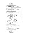
まず、車載装置に設置されたUSBポート402に携帯端末20が差し込まれると、携帯端末接続手段302は、各USBポートの携帯端末20を識別し、制御手段308によってスイッチ404がオンにされ、USBポートを介して携帯端末20に電力が供給され、車載装置20と携帯端末30間との接続が完了する(S101)。携帯端末20と車載装置30とが接続されると、データラインを介してデータや制御信号等の双方向の通信が可能になる。例えば、携帯端末20から出力される音声信号や映像信号が接続ポートを介して車載装置へ入力され、この音声信号や映像信号を車載ディスプレイや車載スピーカから出力することができる。
First, when the
使用状況監視手段304は、接続された携帯端末20の使用状況を監視し(S102)、その監視結果に基づき例えば図5に示すような監視情報を作成しこれを報告する(S103)。各携帯端末20の使用状況は、車載装置30が起動状態で、かつ、携帯端末が接続状態である期間、継続して行われる。
The usage
一方、クランキング検出手段308は、バッテリー検出部406がバッテリーから供給された電圧がしきい値以下になったことを検出し(S104)、かつイグニション検出部408がステータス情報に基づきイグニションスイッチがオン状態であることを検出したとき(S105)。クランキング期間であることを検出する(S106)。
On the other hand, the cranking detection means 308 detects that the voltage supplied from the battery is less than the threshold value by the battery detection unit 406 (S104), and the
クランキングが検出されると、制御手段308は、使用状況監視手段304により作成された監視情報に基づき、切断可能な接続ポートを判別し、各接続ポートへの電力供給を制御する。具体的には、図7に示す制御部250は、切断可能であると判別されたUSBポート402への電力供給が遮断されるようにスイッチ404を開くように制御する。切断不可能と判別された接続ポートのスイッチ404は閉じたままである。制御部250は、クランキング検出手段308によるクランキングが非検出となったことに応答して、スイッチ404を開から閉へ戻し、切断された接続ポートへの電力供給を再開させる。
When the cranking is detected, the
このように本実施例によれば、アイドリングストップ状態からエンジンを再始動させるときに、クランキングによりバッテリーの供給電圧がしきい値以下に降下しても、使用中の携帯端末の動作を継続させることができる。 As described above, according to this embodiment, when the engine is restarted from the idling stop state, even if the battery supply voltage drops below the threshold value due to cranking, the operation of the mobile terminal in use is continued. be able to.
また、車載装置30が図5に示すような種別の異なる接続ポートを備えている場合には、種別に応じて接続ポートの切断または非切断を判別するようにしてもよい。例えば、急速充電を可能にするため、通常規格の接続ポートよりも大きな電流を流すことができる急速充電用の接続ポートが設けられることがある。あるいは、大きな負荷を駆動するための大きな電流を流すことができる大電流用の接続ポートが設けられることがある。このような場合、制御手段308は、通常規格の接続ポートのみが使用されており、その接続ポートを切断不可能と判別したとき、急速充電用または大電流用の接続ポートを自動的に切断するようにしてもよい。
Further, when the in-
さらに、制御手段308は、接続ポートに流せる最大電流が既知であるとき、使用、不使用の接続ポートから消費電力を算出し、消費電力がバッテリーからの許容電力を下回る場合には接続ポートを切断せず、消費電力が許容電力を上回ったときのみ、切断可能な接続ポートを選択し、それらへの電力供給をカットするようにしてもよい。さらに、接続ポートから供給される電力を動的に検出することができるならば、それらの検出された消費電力から切断するのに最適な接続ポートを判別するようにしてもよい。 Further, the control means 308 calculates the power consumption from the used and unused connection ports when the maximum current that can be passed through the connection port is known, and disconnects the connection port if the power consumption is lower than the allowable power from the battery. Instead, only when the power consumption exceeds the allowable power, a disconnectable connection port may be selected and the power supply to them may be cut. Further, if the power supplied from the connection port can be dynamically detected, the optimum connection port for disconnecting from the detected power consumption may be determined.
さらに、制御手段308は、使用中の接続ポートと切断可能な接続ポートとの関係を予め規定するテーブルを用意することができる。例えば、接続ポート1〜4のうち、接続ポート1が使用中であるとき、接続ポート3が切断され、接続ポート2が使用中であるとき、接続ポート4が切断され、接続ポート3が使用中であるとき、接続ポート1、2が切断され、接続ポート4が使用中であるとき、接続ポート2が切断される。
Furthermore, the
以上、本発明の好ましい実施の形態について詳述したが、本発明は、特定の実施形態に限定されるものではなく、特許請求の範囲に記載された本発明の要旨の範囲内において、種々の変形・変更が可能である。 The preferred embodiment of the present invention has been described in detail above, but the present invention is not limited to the specific embodiment, and various modifications can be made within the scope of the present invention described in the claims. Deformation / change is possible.
10:携帯端末接続システム 20:携帯端末
30:車載装置 32:ハンズフリー通話セット
50:USB接続 50:USB接続
300:携帯端末接続プログラム 302:携帯端末接続手段
304:使用状況監視手段 306:クランキング検出手段
308:制御手段 400:USB接続制御システム
402:USBポート 404:スイッチ
406:バッテリー検出部 408:イグニション検出部
10: Mobile terminal connection system 20: Mobile terminal 30: In-vehicle device 32: Hands-free call set 50: USB connection 50: USB connection 300: Mobile terminal connection program 302: Mobile terminal connection means 304: Usage status monitoring means 306: Cranking Detection means 308: Control means 400: USB connection control system 402: USB port 404: Switch 406: Battery detection unit 408: Ignition detection unit
Claims (22)
複数の携帯端末を接続可能であり、かつバッテリーからの電力を供給可能な接続手段と、
前記接続手段により接続された携帯端末の使用状況を監視する監視手段と、
前記バッテリーからの供給電圧がしきい値以下であるか否かを検出する検出手段と、
前記検出手段により供給電圧がしきい値以下であることが検出されたとき、前記監視手段の監視結果に基づき前記接続手段を介しての携帯端末への電力供給を制御する制御手段と、
を有する電子装置。 An electronic device operable by electric power supplied from a battery mounted on a vehicle,
A connection means capable of connecting a plurality of portable terminals and capable of supplying power from a battery;
Monitoring means for monitoring the usage status of the mobile terminal connected by the connection means;
Detecting means for detecting whether the supply voltage from the battery is below a threshold value;
Control means for controlling power supply to the portable terminal via the connection means based on a monitoring result of the monitoring means when the detection means detects that the supply voltage is equal to or lower than a threshold value;
An electronic device.
前記接続ポートを介して接続された携帯端末の使用状況を監視する監視ステップと、
前記バッテリーからの供給電圧がしきい値以下であるか否かを検出する検出ステップと、
前記検出ステップにより供給電圧がしきい値以下であることが検出されたとき、前記監視ステップの監視結果に基づき前記接続ポートを介しての携帯端末への電力供給を制御する制御ステップと、
を有する接続制御方法。 A portable terminal connection control method in an electronic device operable by electric power supplied from a battery mounted on a vehicle, wherein a plurality of portable terminals can be connected via a plurality of connection ports of the electronic device. There,
A monitoring step of monitoring the usage status of the mobile terminal connected via the connection port;
A detection step of detecting whether the supply voltage from the battery is below a threshold;
A control step for controlling power supply to the portable terminal via the connection port based on a monitoring result of the monitoring step when the detection step detects that the supply voltage is equal to or lower than a threshold value;
A connection control method.
前記接続ポートを介して接続された携帯端末の使用状況を監視する監視ステップと、
前記バッテリーからの供給電圧がしきい値以下であるか否かを検出する検出ステップと、
前記検出ステップにより供給電圧がしきい値以下であることが検出されたとき、前記監視ステップの監視結果に基づき前記接続ポートを介しての携帯端末への電力供給を制御する制御ステップと、
を有する電力制御プログラム。 A power control program executed by an electronic device that is operable by electric power supplied from a battery mounted on a vehicle and that can be connected to a plurality of portable terminals via a plurality of connection ports of the electronic device. And
A monitoring step of monitoring the usage status of the mobile terminal connected via the connection port;
A detection step of detecting whether the supply voltage from the battery is below a threshold;
A control step for controlling power supply to the portable terminal via the connection port based on a monitoring result of the monitoring step when the detection step detects that the supply voltage is equal to or lower than a threshold value;
A power control program.
Priority Applications (2)
| Application Number | Priority Date | Filing Date | Title |
|---|---|---|---|
| JP2014007558A JP2015134591A (en) | 2014-01-20 | 2014-01-20 | Electronic device, control method for connection of portable terminal, and electric power control program |
| US14/559,644 US9774685B2 (en) | 2014-01-20 | 2014-12-03 | Electronic device, mobile terminal connection control method, and power control program |
Applications Claiming Priority (1)
| Application Number | Priority Date | Filing Date | Title |
|---|---|---|---|
| JP2014007558A JP2015134591A (en) | 2014-01-20 | 2014-01-20 | Electronic device, control method for connection of portable terminal, and electric power control program |
Publications (1)
| Publication Number | Publication Date |
|---|---|
| JP2015134591A true JP2015134591A (en) | 2015-07-27 |
Family
ID=53544091
Family Applications (1)
| Application Number | Title | Priority Date | Filing Date |
|---|---|---|---|
| JP2014007558A Pending JP2015134591A (en) | 2014-01-20 | 2014-01-20 | Electronic device, control method for connection of portable terminal, and electric power control program |
Country Status (2)
| Country | Link |
|---|---|
| US (1) | US9774685B2 (en) |
| JP (1) | JP2015134591A (en) |
Cited By (12)
| Publication number | Priority date | Publication date | Assignee | Title |
|---|---|---|---|---|
| JP2017077847A (en) * | 2015-10-22 | 2017-04-27 | アルパイン株式会社 | Power supply control device and power supply control method |
| JP2017163275A (en) * | 2016-03-08 | 2017-09-14 | 株式会社ナカヨ | Communication system with power-failure-time preferential power supply function |
| JP2018011435A (en) * | 2016-07-13 | 2018-01-18 | ミツミ電機株式会社 | Charge control circuit of on-vehicle charge connector, on-vehicle charge connector and in-vehicle data transfer and charging system to external equipment |
| KR20180072834A (en) * | 2015-11-16 | 2018-06-29 | 몰렉스 엘엘씨 | Power charging module and method of using same |
| KR20190029884A (en) * | 2017-09-13 | 2019-03-21 | 현대자동차주식회사 | Charing apparatus and vehicle comprising the same, control method for charing apparatus |
| JP2019149091A (en) * | 2018-02-28 | 2019-09-05 | 古野電気株式会社 | On-vehicle device, control method for on-vehicle device, and program |
| JP2020077437A (en) * | 2020-02-07 | 2020-05-21 | 株式会社ワコム | Electronic pen and position detection system |
| WO2020137381A1 (en) * | 2018-12-26 | 2020-07-02 | 株式会社デンソー | Vehicle control device |
| DE102020102907A1 (en) | 2019-02-05 | 2020-08-06 | Panasonic Intellectual Property Management Co., Ltd. | Charge control device and charge control method |
| JP2021044022A (en) * | 2020-02-07 | 2021-03-18 | 株式会社ワコム | Electronic pen and position detection system |
| JP2021176721A (en) * | 2020-05-07 | 2021-11-11 | 株式会社デンソー | Vehicle control system |
| JP2022000815A (en) * | 2020-12-21 | 2022-01-04 | 株式会社ワコム | Electronic pen and position detection system |
Families Citing this family (4)
| Publication number | Priority date | Publication date | Assignee | Title |
|---|---|---|---|---|
| KR102460222B1 (en) * | 2017-12-21 | 2022-10-31 | 현대자동차주식회사 | Charging device for vehicle, vehicle and controlling method for the vehicle |
| WO2020144033A1 (en) * | 2019-01-07 | 2020-07-16 | Continental Automotive Gmbh | Power delivery device |
| JP7196779B2 (en) * | 2019-06-11 | 2022-12-27 | 株式会社デンソー | In-vehicle control system |
| JP2024000774A (en) * | 2022-06-21 | 2024-01-09 | アルプスアルパイン株式会社 | Power distribution device |
Family Cites Families (4)
| Publication number | Priority date | Publication date | Assignee | Title |
|---|---|---|---|---|
| JP3515402B2 (en) * | 1998-12-18 | 2004-04-05 | 株式会社日立製作所 | Power network equipment |
| JP2004106621A (en) | 2002-09-17 | 2004-04-08 | Nissan Motor Co Ltd | Automatic stopping/automatic restarting device for engine |
| JP2007191097A (en) | 2006-01-20 | 2007-08-02 | Fujitsu Ten Ltd | Vehicle control device and vehicle control method |
| JP2010202023A (en) * | 2009-03-03 | 2010-09-16 | Omron Corp | Vehicle power supply system |
-
2014
- 2014-01-20 JP JP2014007558A patent/JP2015134591A/en active Pending
- 2014-12-03 US US14/559,644 patent/US9774685B2/en active Active
Cited By (24)
| Publication number | Priority date | Publication date | Assignee | Title |
|---|---|---|---|---|
| JP2017077847A (en) * | 2015-10-22 | 2017-04-27 | アルパイン株式会社 | Power supply control device and power supply control method |
| KR102163525B1 (en) * | 2015-11-16 | 2020-10-08 | 몰렉스 엘엘씨 | Power charging module and method of using the same |
| KR20180072834A (en) * | 2015-11-16 | 2018-06-29 | 몰렉스 엘엘씨 | Power charging module and method of using same |
| JP2018535645A (en) * | 2015-11-16 | 2018-11-29 | モレックス エルエルシー | Power charging module and method of using the same |
| US10897147B2 (en) | 2015-11-16 | 2021-01-19 | Molex, Llc | Power charging module and temperature-based methods of using same |
| JP2017163275A (en) * | 2016-03-08 | 2017-09-14 | 株式会社ナカヨ | Communication system with power-failure-time preferential power supply function |
| JP2018011435A (en) * | 2016-07-13 | 2018-01-18 | ミツミ電機株式会社 | Charge control circuit of on-vehicle charge connector, on-vehicle charge connector and in-vehicle data transfer and charging system to external equipment |
| KR20190029884A (en) * | 2017-09-13 | 2019-03-21 | 현대자동차주식회사 | Charing apparatus and vehicle comprising the same, control method for charing apparatus |
| KR102416128B1 (en) | 2017-09-13 | 2022-07-04 | 현대자동차주식회사 | Charing apparatus and vehicle comprising the same, control method for charing apparatus |
| JP2019149091A (en) * | 2018-02-28 | 2019-09-05 | 古野電気株式会社 | On-vehicle device, control method for on-vehicle device, and program |
| JP7102168B2 (en) | 2018-02-28 | 2022-07-19 | 古野電気株式会社 | On-board unit, on-board unit control method, and program |
| JP2020108198A (en) * | 2018-12-26 | 2020-07-09 | 株式会社デンソー | Vehicular control device |
| WO2020137381A1 (en) * | 2018-12-26 | 2020-07-02 | 株式会社デンソー | Vehicle control device |
| JP7225791B2 (en) | 2018-12-26 | 2023-02-21 | 株式会社デンソー | vehicle controller |
| JP7228790B2 (en) | 2019-02-05 | 2023-02-27 | パナソニックIpマネジメント株式会社 | Charge control device and charge control method |
| JP2020127308A (en) * | 2019-02-05 | 2020-08-20 | パナソニックIpマネジメント株式会社 | Charge control device and charge control method |
| DE102020102907A1 (en) | 2019-02-05 | 2020-08-06 | Panasonic Intellectual Property Management Co., Ltd. | Charge control device and charge control method |
| US11524602B2 (en) | 2019-02-05 | 2022-12-13 | Panasonic Intellectual Property Management Co., Ltd. | Charge control device and charge control method |
| JP2021044022A (en) * | 2020-02-07 | 2021-03-18 | 株式会社ワコム | Electronic pen and position detection system |
| JP2020077437A (en) * | 2020-02-07 | 2020-05-21 | 株式会社ワコム | Electronic pen and position detection system |
| JP2021176721A (en) * | 2020-05-07 | 2021-11-11 | 株式会社デンソー | Vehicle control system |
| JP7456270B2 (en) | 2020-05-07 | 2024-03-27 | 株式会社デンソー | vehicle control system |
| JP2022000815A (en) * | 2020-12-21 | 2022-01-04 | 株式会社ワコム | Electronic pen and position detection system |
| JP7144584B2 (en) | 2020-12-21 | 2022-09-29 | 株式会社ワコム | Electronic pen and position detection system |
Also Published As
| Publication number | Publication date |
|---|---|
| US9774685B2 (en) | 2017-09-26 |
| US20150203059A1 (en) | 2015-07-23 |
Similar Documents
| Publication | Publication Date | Title |
|---|---|---|
| JP2015134591A (en) | Electronic device, control method for connection of portable terminal, and electric power control program | |
| EP2752775B1 (en) | Portable charging apparatus, charging method thereof, and charging system | |
| US8295532B2 (en) | Method and system for wireless headset instant on capability during battery charging | |
| RU2564989C2 (en) | Providing power to accessory during portable computing device hibernation | |
| US8229144B2 (en) | Method and system for switched battery charging and loading in a stereo headset | |
| US8719611B2 (en) | Checking functional module ID in connected extension device to power instead of existing corresponding functional module | |
| JP2015212930A (en) | Method and apparatus for determining direction of power delivery | |
| JP4350665B2 (en) | Electronic device, charging system, and power supply method | |
| JP2007284053A (en) | Power control system of vehicle | |
| JP5804925B2 (en) | Automotive electronic devices | |
| CN114977343A (en) | Charging method, charging device, electronic equipment and storage medium | |
| CN108879874A (en) | It is a kind of can the intelligent vehicle of interactive voice fill | |
| CN111193978A (en) | Charging box control method, earphone charging box and computer readable storage medium | |
| CN111601290B (en) | Bluetooth sound box, earphone, bluetooth audio playing device, bluetooth sound box system and Bluetooth audio switching method | |
| CN111596881B (en) | Audio playing device, audio playing system, switching method, bluetooth sound box and Bluetooth earphone | |
| JP2012035779A (en) | In-vehicle device | |
| JP2017013695A (en) | On-vehicle device | |
| JP2009081746A (en) | Portable content processing apparatus, control method, and program | |
| JP2015018378A (en) | Electrical apparatus | |
| KR100670834B1 (en) | Method and apparatus for managing the power on telematics terminal | |
| KR101282305B1 (en) | Multi-terminal assembly with uninterruptible power supply function | |
| KR20170045644A (en) | Apparatus and method for supporting multi-function of vehicle | |
| CN110351900B (en) | Electronic device | |
| JP2010119277A (en) | Charging device and method, and program | |
| US10534574B2 (en) | Acoustic system and volume adjustment method |