JP2015113065A - Dump truck - Google Patents

Dump truck Download PDF

Info

Publication number
JP2015113065A
JP2015113065A JP2013258014A JP2013258014A JP2015113065A JP 2015113065 A JP2015113065 A JP 2015113065A JP 2013258014 A JP2013258014 A JP 2013258014A JP 2013258014 A JP2013258014 A JP 2013258014A JP 2015113065 A JP2015113065 A JP 2015113065A
Authority
JP
Japan
Prior art keywords
frame
pin
loading platform
hoist cylinder
long hole
Prior art date
Legal status (The legal status is an assumption and is not a legal conclusion. Google has not performed a legal analysis and makes no representation as to the accuracy of the status listed.)
Pending
Application number
JP2013258014A
Other languages
Japanese (ja)
Inventor
石原 和典
Kazunori Ishihara
和典 石原
北口 篤
Atsushi Kitaguchi
篤 北口
毅 岩城
Takeshi Iwaki
毅 岩城
池田 純
Jun Ikeda
純 池田
泰樹 北
Yasuki Kita
泰樹 北
Current Assignee (The listed assignees may be inaccurate. Google has not performed a legal analysis and makes no representation or warranty as to the accuracy of the list.)
Hitachi Construction Machinery Co Ltd
Original Assignee
Hitachi Construction Machinery Co Ltd
Priority date (The priority date is an assumption and is not a legal conclusion. Google has not performed a legal analysis and makes no representation as to the accuracy of the date listed.)
Filing date
Publication date
Application filed by Hitachi Construction Machinery Co Ltd filed Critical Hitachi Construction Machinery Co Ltd
Priority to JP2013258014A priority Critical patent/JP2015113065A/en
Publication of JP2015113065A publication Critical patent/JP2015113065A/en
Pending legal-status Critical Current

Links

Images

Landscapes

  • Body Structure For Vehicles (AREA)

Abstract

PROBLEM TO BE SOLVED: To prevent an impact on a hoist cylinder while unloading and improve the durability and service life of the hoist cylinder.SOLUTION: A dump truck 1 is provided with a damping force generation mechanism 24 for generating a damping force when a hoist cylinder 23 reaches a predetermined extended position. The damping force generation mechanism 24 is composed of: a frame-side bracket 25 that is provided in a frame 3 and has a frame-side pin hole 25A; a dump-bed-side bracket 27 that is provided in a dump bed 16 and has a dump-bed-side long hole 27A extending rearward; and a damper 29 that is attached to the frame-side bracket 25 via a lower pin 26 and attached to the dump-bed-side bracket 27 via an upper pin 28. The upper pin 28 is attached movably along the dump-bed-side long hole 27A, and the lower pin 26 is attached rotatably to the frame-side pin hole 25A.

Description

本発明は、例えば露天の採掘場、石切り場、鉱山で採掘した鉱物または掘削した土砂等を運搬するのに好適に用いられるダンプトラックに関する。   The present invention relates to a dump truck that is suitably used for transporting, for example, open-pit mines, quarries, minerals mined in mines, or excavated earth and sand.

一般に、ダンプトラックは、車体のフレーム上に起伏可能となった荷台を備え、この荷台に運搬対象の荷物(例えば、鉱物や土砂等)を多量に積載し、この状態で荷物の運搬、搬送を行うものである。   In general, a dump truck has a loading platform that can be raised and lowered on the frame of a vehicle body, and a large amount of cargo to be transported (for example, minerals and earth and sand) is loaded on this loading platform, and in this state, the cargo is transported and transported. Is what you do.

この種の従来技術によるダンプトラックは、前,後方向に延び支持構造体を形成するフレームと、該フレームの後端にヒンジピンを介して傾動可能に設けられた荷台と、該荷台と前記フレームとの間に伸縮可能に設けられ伸長時に前記ヒンジピンを中心として前記荷台を立上るように傾斜させるホイストシリンダを備えている。   A dump truck according to this type of prior art includes a frame that extends in the front and rear directions to form a support structure, a cargo bed that is tiltably provided at the rear end of the frame via a hinge pin, the cargo bed, and the frame. The hoist cylinder is provided so as to be expandable and contractable, and tilts so that the cargo bed rises around the hinge pin when extended.

このようなダンプトラックは、荷台に荷物を積載した状態で運搬先まで自走した後に、ホイストシリンダを伸長させて荷台を斜め後方に持上げ、この持上げ動作により傾斜した荷台に沿って荷物を荷降し場へと排出する。   In such a dump truck, after self-propelled to the destination with the load loaded on the loading platform, the hoist cylinder is extended to lift the loading platform diagonally backward, and the lifting operation unloads the load along the inclined loading platform. Discharge to the quarry.

この場合、荷台を傾動可能に支持しているヒンジピンには、荷台の重量と荷物の重量との重心により、ヒンジピン回りのモーメントが発生する。このモーメントにより、ホイストシリンダには、圧縮側(縮小側)の荷重または引っ張り側(伸長側)の荷重が発生する。   In this case, a moment around the hinge pin is generated in the hinge pin that supports the load bed so as to be tiltable due to the center of gravity of the weight of the load bed and the weight of the load. Due to this moment, a load on the compression side (reduction side) or a load on the tension side (extension side) is generated in the hoist cylinder.

ホイストシリンダを伸ばし始めたときには、荷台と荷物との重心がヒンジピンよりも前側に位置しているので、ヒンジピンに作用するモーメントは荷台を傾伏させる方向に発生する。その結果、ホイストシリンダには、圧縮側の荷重が発生する。しかし、ホイストシリンダを大きく伸ばして荷台を傾斜させ、荷台と荷物との重心がヒンジピンよりも後側になった場合には、ヒンジピンに作用するモーメントは、荷台を立上げる方向に逆転して発生するので、ホイストシリンダには、引っ張り側の荷重が発生する。   When the hoist cylinder starts to extend, the center of gravity of the cargo bed and the load is located on the front side of the hinge pin, so that the moment acting on the hinge pin is generated in the direction of tilting the cargo bed. As a result, a compression-side load is generated in the hoist cylinder. However, when the hoist cylinder is greatly extended to tilt the loading platform, and the center of gravity of the loading platform and the load is on the rear side of the hinge pin, the moment acting on the hinge pin is generated by reversing the direction in which the loading platform is raised. Therefore, a load on the pulling side is generated in the hoist cylinder.

この場合、例えばホイストシリンダが最伸長に達する直前で、ホイストシリンダに引っ張り荷重が発生すると、ホイストシリンダのチューブ(ロッドガイド)とチューブ内を摺動しているピストンとが衝突してホイストシリンダに強い衝撃が起こることがある。そこで、例えば特許文献1のように、シリンダが最伸長に達するときに流体(圧油)の絞りによる流体抵抗を利用したクッション機能を有するシリンダが知られている。   In this case, for example, when a tensile load is generated in the hoist cylinder immediately before the hoist cylinder reaches maximum extension, the hoist cylinder tube (rod guide) and the piston sliding in the tube collide to be strong against the hoist cylinder. Shock may occur. Therefore, for example, as in Patent Document 1, a cylinder having a cushion function using a fluid resistance due to a restriction of fluid (pressure oil) when the cylinder reaches maximum extension is known.

また、例えば特許文献2のように、油圧ポンプとホイストシリンダとの間にホイストバルブを設けて、ホイストシリンダが最伸長に達するときにホイストバルブによりホイストシリンダに供給される圧油の供給量を調節するものが知られている。さらに、例えば特許文献3のように、荷台の振動を抑制するために、フレームと荷台との間にダンパを連結するものが知られている。   Also, as in Patent Document 2, for example, a hoist valve is provided between the hydraulic pump and the hoist cylinder, and the supply amount of pressure oil supplied to the hoist cylinder by the hoist valve is adjusted when the hoist cylinder reaches the maximum extension. What to do is known. Further, for example, as disclosed in Patent Document 3, a damper is known in which a damper is connected between the frame and the loading platform in order to suppress the vibration of the loading platform.

特開昭59−80512号公報JP 59-80512 A 特開2001−105956号公報JP 2001-105956 A 特開2011−5932号公報JP 2011-5932 A

ところで、上述した特許文献1によるシリンダは、最伸長に達するときのクッション機能を有しているが、ホイストシリンダに適用しても、最大伸長前に起きる衝撃をクッション機能で抑えることはできない。   By the way, although the cylinder by patent document 1 mentioned above has a cushion function when reaching the maximum extension, even if it applies to a hoist cylinder, the impact which occurs before the maximum extension cannot be suppressed by the cushion function.

また、上述した特許文献2のように、油圧ポンプとホイストシリンダとの間にホイストバルブを設け、圧油の供給量を調節する場合にも、油圧回路の構成が複雑になるという問題がある。   Further, as in Patent Document 2 described above, there is a problem that the configuration of the hydraulic circuit becomes complicated even when a hoist valve is provided between the hydraulic pump and the hoist cylinder to adjust the supply amount of the pressure oil.

さらに、特許文献3のように、フレームと荷台との間にダンパを設けた場合には、荷台がフレームに着座した状態から荷物を排出するまでの全域で減衰力を発生させてしまう。その結果、ホイストシリンダに圧縮荷重が作用しているときに、さらに抵抗を与えてしまうという問題がある。   Further, when a damper is provided between the frame and the loading platform as in Patent Document 3, a damping force is generated in the entire region from the state where the loading platform is seated on the frame until the cargo is discharged. As a result, there is a problem that resistance is further applied when a compressive load is applied to the hoist cylinder.

本発明は上述した従来技術の問題に鑑みなされたもので、本発明の目的は、荷物の排出時にホイストシリンダに衝撃が生じるのを抑制し、ホイストシリンダの耐久性、寿命を向上させることができるようにしたダンプトラックを提供することにある。   The present invention has been made in view of the above-described problems of the prior art, and an object of the present invention is to suppress the occurrence of an impact on the hoist cylinder when the load is discharged, thereby improving the durability and life of the hoist cylinder. The purpose is to provide a dump truck.

上述した課題を解決するため本発明は、前,後方向に延び支持構造体を形成するフレームと、該フレームの後端にヒンジピンを介して傾動可能に設けられた荷台と、前記フレームと前記荷台との間に伸縮可能に設けられ伸長時に前記ヒンジピンを中心として前記荷台を立上るように傾斜させるホイストシリンダと、該ホイストシリンダが予め決められた伸長位置に到達したときに減衰力を発生させる減衰力発生機構とを備えたダンプトラックに適用される。   In order to solve the above-described problems, the present invention provides a frame that extends in the forward and rearward directions to form a support structure, a cargo bed provided at a rear end of the frame so as to be tiltable via a hinge pin, the frame, and the cargo bed. A hoist cylinder which is provided so as to be extendable between the hoist cylinder and tilts so that the loading platform rises around the hinge pin when extended, and a damping which generates a damping force when the hoist cylinder reaches a predetermined extended position Applies to dump trucks with force generation mechanism.

そして、請求項1の発明が採用する構成の特徴は、前記減衰力発生機構は、前記フレームに設けられたフレーム側ブラケットと、前記荷台に設けられた荷台側ブラケットと、一側がロアピンを介して前記フレーム側ブラケットに取付けられ他側がアッパピンを介して前記荷台側ブラケットに取付けられたダンパとにより構成し、前記フレーム側ブラケットと前記荷台側ブラケットのうちいずれか一方のブラケットには、前,後方向に延びる長孔を設け、他方のブラケットには、ピン孔を設ける構成とし、前記アッパピンと前記ロアピンのうちいずれか一方のピンは、前記長孔に沿って移動可能に取付けられ、他方のピンは、前記ピン孔に回転可能に取付けられる構成としたことにある。   The invention adopts the feature that the damping force generating mechanism includes a frame-side bracket provided on the frame, a cargo-side bracket provided on the cargo bed, and one side via a lower pin. A damper is attached to the frame side bracket and the other side is attached to the cargo bed side bracket via an upper pin. Either one of the frame side bracket and the load bed side bracket has a front and rear direction. The other bracket is provided with a pin hole, and one of the upper pin and the lower pin is movably attached along the long hole, and the other pin is In this configuration, the pin hole is rotatably attached.

また、請求項2の発明によると、前記長孔は、前記荷台側ブラケットに対して前,後方向に長い荷台側長孔であり、前記ダンパは、前記ロアピンが前記フレーム側ブラケットのフレーム側ピン孔に回転可能に取付けられ、前記アッパピンが前記荷台側長孔に沿って移動可能に取付けられる構成としたことにある。   According to a second aspect of the present invention, the elongated hole is a loading platform side elongated hole that is long in the front and rear directions with respect to the loading platform side bracket, and the damper is configured such that the lower pin is a frame side pin of the frame side bracket. The upper pin is rotatably attached to the hole, and the upper pin is attached to be movable along the loading platform side long hole.

また、請求項3の発明によると、前記長孔は、前記フレーム側ブラケットに対して前,後方向に長いフレーム側長孔であり、前記ダンパは、前記アッパピンが前記荷台側ブラケットの荷台側ピン孔に回転可能に取付けられ、前記ロアピンが前記フレーム側長孔に沿って移動可能に取付けられる構成としたことにある。   According to a third aspect of the present invention, the long hole is a frame side long hole that is long in the front and rear directions with respect to the frame side bracket, and the damper has the upper pin serving as a load side pin of the load side bracket. The lower pin is rotatably attached to the hole, and the lower pin is attached to be movable along the frame side long hole.

また、請求項4の発明によると、前記ダンパは、チューブと、一端側が前記チューブ内に摺動可能に設けられたピストンに固定され他端側が前記チューブから突出したロッドとにより構成し、前記チューブ内には、前記ロッドの外周側に位置して前記ロッドを縮小させる方向に付勢する戻しばねを設ける構成としたことにある。   According to a fourth aspect of the present invention, the damper includes a tube and a rod having one end fixed to a piston slidably provided in the tube and the other end protruding from the tube. Inside, there is a configuration in which a return spring is provided which is located on the outer peripheral side of the rod and urges the rod in a shrinking direction.

請求項1の発明によれば、アッパピンとロアピンのうちいずれか一方のピンは、フレーム側ブラケットと荷台側ブラケットとのうちいずれか一方のブラケットに設けられた長孔に沿って移動可能に取付けられ、他方のピンは、他方のブラケットに設けられたピン孔に回転可能に取付けられる。   According to the first aspect of the present invention, either one of the upper pin and the lower pin is attached to be movable along a long hole provided in one of the frame side bracket and the cargo bed side bracket. The other pin is rotatably attached to a pin hole provided in the other bracket.

これにより、ホイストシリンダが伸び始めてから所定の長さに達するまでは、一方のピンが長孔に沿って移動する。この場合、ダンパは減衰力を発生させないので、ホイストシリンダは抵抗を受けることなく速やかに伸長することができる。そして、ホイストシリンダがさらに伸びて、ホイストシリンダに引っ張り側の荷重が発生するときには、長孔に沿って移動していた一方のピンが長孔の端部(終端)に到達してその移動が規制されてダンパが伸び、減衰力を発生させる。その結果、ホイストシリンダに抵抗を与えてホイストシリンダの伸長動作を抑制することができ、ホイストシリンダの耐久性、寿命を向上することができる。   Thereby, one pin moves along a long hole until it reaches predetermined length after a hoist cylinder begins to extend. In this case, since the damper does not generate a damping force, the hoist cylinder can be quickly extended without receiving resistance. When the hoist cylinder further expands and a load on the pull side is generated in the hoist cylinder, one pin that has moved along the long hole reaches the end (terminal) of the long hole and the movement is restricted. As a result, the damper extends and generates a damping force. As a result, resistance can be given to the hoist cylinder to suppress the extension operation of the hoist cylinder, and the durability and life of the hoist cylinder can be improved.

請求項2の発明によれば、ホイストシリンダが伸び始めてから所定の長さに達するまでは、アッパピンが荷台側長孔に沿って移動するので、ダンパは伸長しない。従って、ダンパは減衰力を発生させないので、ホイストシリンダは抵抗を受けることなく速やかに伸長動作を行うことができる。そして、ホイストシリンダがさらに伸びて、ホイストシリンダに引っ張り側の荷重が作用するときには、荷台側長孔に沿って移動していたアッパピンが荷台側長孔の端部(終端)に到達してその移動が規制されるので、ダンパが伸長する。従って、ダンパは減衰力を発生させるので、ホイストシリンダに抵抗を与えてホイストシリンダがこれ以上伸びるのを抑えることができ、ホイストシリンダの耐久性、寿命を向上することができる。   According to the invention of claim 2, the damper does not extend because the upper pin moves along the loading platform side long hole until the hoist cylinder reaches a predetermined length after starting to extend. Therefore, since the damper does not generate a damping force, the hoist cylinder can perform the extension operation quickly without receiving resistance. When the hoist cylinder is further extended and a load on the pulling side acts on the hoist cylinder, the upper pin that has moved along the loading platform side long hole reaches the end (terminal) of the loading platform side long hole and moves there. Is regulated, so the damper extends. Therefore, since the damper generates a damping force, it is possible to prevent the hoist cylinder from extending further by giving resistance to the hoist cylinder, and to improve the durability and life of the hoist cylinder.

請求項3の発明によれば、ホイストシリンダが伸び始めてから所定の長さに達するまでは、ロアピンがフレーム側長孔に沿って移動する。この場合、ダンパは減衰力を発生させないので、ホイストシリンダは抵抗を受けることなく速やかに伸長動作を行うことができる。そして、ホイストシリンダがさらに伸びて、ホイストシリンダに引っ張り側の荷重が作用するときには、フレーム側長孔に沿って移動していたロアピンが荷台側長孔の端部(終端)に到達してその移動が規制されるので、ダンパが伸長する。従って、ダンパは、減衰力を発生させるので、ホイストシリンダに抵抗を与えてホイストシリンダがこれ以上伸びるのを抑えることができ、ホイストシリンダの耐久性、寿命を向上することができる。   According to the invention of claim 3, the lower pin moves along the frame-side long hole from when the hoist cylinder starts to extend until it reaches a predetermined length. In this case, since the damper does not generate a damping force, the hoist cylinder can perform the extension operation quickly without receiving resistance. When the hoist cylinder further expands and a pull-side load is applied to the hoist cylinder, the lower pin that has moved along the frame-side long hole reaches the end (terminal) of the load-side long hole and moves there. Is regulated, so the damper extends. Therefore, since the damper generates a damping force, it is possible to prevent the hoist cylinder from extending further by giving resistance to the hoist cylinder, and to improve the durability and life of the hoist cylinder.

請求項4の発明によれば、ダンパのチューブ内には、ロッドを縮小させる方向に付勢する戻しばねを設けているので、ホイストシリンダが縮小するときに、ダンパをスムーズに縮小させることができ、ホイストシリンダの次なる伸長動作に備えることができる。   According to the invention of claim 4, since the return spring for urging the rod in the direction of reducing the rod is provided in the tube of the damper, the damper can be smoothly reduced when the hoist cylinder is reduced. The hoist cylinder can be prepared for the next extension operation.

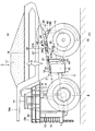
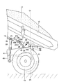
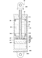
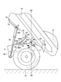
本発明の第1の実施の形態によるダンプトラックを示す正面図である。1 is a front view showing a dump truck according to a first embodiment of the present invention. ダンプトラックの荷台を斜め後方に傾斜させ始めた状態で、ホイストシリンダ、減衰力発生機構等を示す拡大正面図である。It is an enlarged front view which shows a hoist cylinder, a damping force generation mechanism, etc. in the state which started tilting the loading platform of a dump truck diagonally backward. ダンプトラックの荷台を斜め後方に傾斜させた途中状態で、ホイストシリンダ、減衰力発生機構等を示す拡大正面図である。It is an enlarged front view which shows a hoist cylinder, a damping force generation mechanism, etc. in the state in which the loading platform of the dump truck is inclined obliquely rearward. ダンプトラックの荷台を斜め後方に大きく傾斜させた状態で、ホイストシリンダ、減衰力発生機構等を示す拡大正面図である。It is an enlarged front view which shows a hoist cylinder, a damping force generation mechanism, etc. in the state which inclined the loading platform of the dump truck largely diagonally backward. ダンパを単体で示す縦断面図である。It is a longitudinal cross-sectional view which shows a damper alone. 本発明の第2の実施の形態によるダンプトラックを示す正面図である。It is a front view which shows the dump truck by the 2nd Embodiment of this invention. ダンプトラックの荷台を斜め後方に大きく傾斜させた状態で、ホイストシリンダ、減衰力発生機構等を示す拡大正面図である。It is an enlarged front view which shows a hoist cylinder, a damping force generation mechanism, etc. in the state which inclined the loading platform of the dump truck largely diagonally backward.

以下、本発明に係るダンプトラックの実施の形態について、鉱山で採掘した鉱物や土砂等を運搬する大型のダンプトラックを例に挙げ、添付図面に従って詳細に説明する。   Hereinafter, embodiments of the dump truck according to the present invention will be described in detail with reference to the accompanying drawings, taking as an example a large dump truck for transporting minerals and earth and sand mined in a mine.

図1ないし図5は本発明の第1の実施の形態を示している。図中、1は大型の運搬車両であるダンプトラックで、該ダンプトラック1は、図1に示すように頑丈なフレーム構造をなす車体2と、該車体2上に傾動(起伏)可能に搭載された後述の荷台16とにより大略構成されている。そして、車体2は、後述のフレーム3、建屋12、キャブ14等を含んで構成されている。   1 to 5 show a first embodiment of the present invention. In the figure, reference numeral 1 denotes a dump truck, which is a large transport vehicle. The dump truck 1 is mounted on a vehicle body 2 having a sturdy frame structure as shown in FIG. In addition, it is generally constituted by a loading platform 16 described later. And the vehicle body 2 is comprised including the below-mentioned frame 3, the building 12, the cab 14, etc.

3は車体2のシャーシを構成するフレームで、該フレーム3は、前,後方向に延びる強固な支持構造体(溶接による製缶構造体)として形成されている。そして、フレーム3は、前,後方向に延びるベースフレーム4と、該ベースフレーム4の前,後方向の中間部に配置された上部横梁5とにより構成されている。   Reference numeral 3 denotes a frame constituting the chassis of the vehicle body 2, and the frame 3 is formed as a strong support structure (can manufacturing structure by welding) extending in the front and rear directions. The frame 3 includes a base frame 4 extending in the front and rear directions, and an upper horizontal beam 5 disposed at an intermediate portion in the front and rear directions of the base frame 4.

ここで、ベースフレーム4は、下方に向けて突出した左,右のシリンダ取付部4A(左側のみ図示)と、後端側で後向きに突設された左,右一対の荷台取付部4B(左側のみ図示)とを有している。   Here, the base frame 4 includes a left and right cylinder mounting portion 4A projecting downward (only the left side is shown) and a pair of left and right cargo bed mounting portions 4B projecting rearward on the rear end side (left side). Only shown).

左,右のシリンダ取付部4Aには、後述するホイストシリンダ23のロッド側が取付けられる。左,右の荷台取付部4Bには、ヒンジピン孔(図示せず)が厚さ方向に穿設され、前記ヒンジピン孔に挿通されたヒンジピン6を介して後述する荷台16が傾動可能に取付けられる構成となっている。また、荷台取付部4Bよりも前側でベースフレーム4の上面には、後述のフレーム側ブラケット25が設けられている。   The rod side of the hoist cylinder 23 described later is attached to the left and right cylinder attachment portions 4A. A hinge pin hole (not shown) is drilled in the thickness direction in the left and right loading platform mounting portions 4B, and a loading platform 16 to be described later is tiltably mounted via a hinge pin 6 inserted through the hinge pin hole. It has become. Further, a frame-side bracket 25 described later is provided on the upper surface of the base frame 4 in front of the loading platform mounting portion 4B.

そして、ベースフレーム4の上面には、後述の荷台16が着座する構成となっている。また、ベースフレーム4の前端側には、左下側デッキ7と右下側デッキ(図示せず)が取付けられる構成となっている。   A loading platform 16 (described later) is seated on the upper surface of the base frame 4. Further, a lower left deck 7 and a lower right deck (not shown) are attached to the front end side of the base frame 4.

8は車体2の前部側に回転可能に設けられた左,右の前輪(左側のみ図示)で、該各前輪8は、ダンプトラック1のオペレータによって操舵(ステアリング操作)される操舵輪を構成するものである。そして、左,右の前輪8は後述の後輪10と同様に、例えば2〜4メートルに及ぶタイヤ径(外径寸法)をもって形成されている。   Reference numeral 8 denotes left and right front wheels (only the left side is shown) that are rotatably provided on the front side of the vehicle body 2, and each front wheel 8 constitutes a steering wheel that is steered (steered) by an operator of the dump truck 1. To do. The left and right front wheels 8 are formed with a tire diameter (outer diameter size) of, for example, 2 to 4 meters, as in the later-described rear wheel 10.

9は前輪8を車体2に対して支持する左,右一対の前輪側サスペンションを示している(左側のみ図示)。該前輪側サスペンション9は、例えば油圧緩衝器等により構成され、ベースフレーム4と前輪8との間に伸縮可能に取付けられている。そして、前輪側サスペンション9は、路面の凹凸等に伴って前輪8が振動しても、この振動が車体2の前部側に伝わるのを緩衝するものである。   Reference numeral 9 denotes a pair of left and right front wheel side suspensions for supporting the front wheel 8 with respect to the vehicle body 2 (only the left side is shown). The front wheel suspension 9 is constituted by, for example, a hydraulic shock absorber or the like, and is attached between the base frame 4 and the front wheel 8 so as to extend and contract. The front wheel side suspension 9 buffers the vibration transmitted to the front side of the vehicle body 2 even when the front wheel 8 vibrates due to road surface unevenness or the like.

10は車体2の後部側に回転可能に設けられた左,右の後輪で、該各後輪10は、ダンプトラック1の駆動輪を構成し、走行駆動装置(図示せず)により回転駆動されるものである。   Reference numeral 10 denotes left and right rear wheels rotatably provided on the rear side of the vehicle body 2, and each rear wheel 10 constitutes a drive wheel of the dump truck 1 and is rotationally driven by a travel drive device (not shown). It is what is done.

11は後輪10を車体2に対して支持する左,右一対の後輪側サスペンションを示している(左側のみ図示)。該後輪側サスペンション11は、例えば油圧緩衝器等により構成され、ベースフレーム4の荷台取付部4Bと後輪10との間に伸縮可能に取付けられている。そして、後輪側サスペンション11は、後輪10の振動が車体2の後部側に伝わるのを緩衝するものである。   Reference numeral 11 denotes a pair of left and right rear wheel suspensions for supporting the rear wheel 10 with respect to the vehicle body 2 (only the left side is shown). The rear wheel side suspension 11 is configured by, for example, a hydraulic shock absorber or the like, and is attached between the cargo bed mounting portion 4B of the base frame 4 and the rear wheel 10 so as to be extendable and contractable. The rear wheel side suspension 11 cushions the vibration of the rear wheel 10 from being transmitted to the rear side of the vehicle body 2.

12はフレーム3の前端側に設けられた建屋で、該建屋12は、フレーム3等と共に車体2の一部を構成するものである。建屋12は、四角形の枠状に形成され、その内部にはエンジン、ラジエータ等の熱交換装置(いずれも図示せず)が収容される。   A building 12 is provided on the front end side of the frame 3, and the building 12 constitutes a part of the vehicle body 2 together with the frame 3 and the like. The building 12 is formed in a rectangular frame shape, and a heat exchange device such as an engine and a radiator (none of which are shown) is accommodated therein.

13は建屋12の上側に配設された上側デッキを示し、該上側デッキ13は、フレーム3、建屋12等と共に車体2の一部を構成するものである。ここで、上側デッキ13は、水平方向に延びる平板状をなし、建屋12とフレーム3とによって下側から支持されることにより、左,右の前輪8よりも上方となる位置に配置されている。また、上側デッキ13の外周側には、メンテナンス作業等を行うときの安全性を確保する手摺り13Aが設けられている。   Reference numeral 13 denotes an upper deck disposed on the upper side of the building 12, and the upper deck 13 constitutes a part of the vehicle body 2 together with the frame 3, the building 12, and the like. Here, the upper deck 13 has a flat plate shape extending in the horizontal direction, and is supported at a position above the left and right front wheels 8 by being supported from below by the building 12 and the frame 3. . A handrail 13A is provided on the outer peripheral side of the upper deck 13 to ensure safety when performing maintenance work or the like.

14は上側デッキ13上に配置されたキャブで、該キャブ14は、フレーム3と建屋12とによって下側から支持されている。そして、キャブ14は、その内部にオペレータが乗込む運転室を画成するもので、キャブ14内には、運転席、操舵用のハンドル、始動スイッチ、アクセルペダル、ブレーキペダルおよび操作レバー(いずれも図示せず)等が設けられている。   Reference numeral 14 denotes a cab arranged on the upper deck 13, and the cab 14 is supported from below by the frame 3 and the building 12. The cab 14 defines a driver's cab in which an operator gets inside. The cab 14 includes a driver's seat, a steering handle, a start switch, an accelerator pedal, a brake pedal, and an operation lever (all of which are Etc.) are provided.

15は車体2の前面側に設けられた乗降用ステップを示している。該乗降用ステップ15は、オペレータ等が上側デッキ13に乗降するときの足場を構成するもので、右下側デッキから上側デッキ13上のキャブ14に向けて斜め上向きに延びる階段状に形成されている。   Reference numeral 15 denotes a boarding / alighting step provided on the front side of the vehicle body 2. The step 15 for getting on and off constitutes a scaffold when an operator or the like gets on and off the upper deck 13 and is formed in a step shape extending obliquely upward from the lower right deck toward the cab 14 on the upper deck 13. Yes.

16は車体2上に傾動可能に搭載された荷台を示し、該荷台16は、例えば油圧ショベル(図示せず)によって採掘された大量の鉱物や土砂等(以下、土砂17という)を受入れるものである。この荷台16は、鉱物や土砂等を多量に積載するため、全長が10〜14メートルにも及ぶ大型の容器として成されている。荷台16の前部側には、その上端部から前方に向けて水平に延びる庇部16Aが一体に設けられ、この庇部16Aは、キャブ14を上側から覆った状態で上側デッキ13の前端部近傍まで延びている。   Reference numeral 16 denotes a loading platform that is tiltably mounted on the vehicle body 2. The loading platform 16 receives a large amount of minerals, earth and sand (hereinafter referred to as earth and sand 17) mined by a hydraulic excavator (not shown), for example. is there. The loading platform 16 is formed as a large container having a total length of 10 to 14 meters in order to load a large amount of minerals and earth and sand. On the front side of the loading platform 16, a flange 16 </ b> A that extends horizontally from the upper end to the front is integrally provided, and the flange 16 </ b> A covers the cab 14 from above and the front end of the upper deck 13. It extends to the vicinity.

ここで、荷台16の下面16Bの中央部には、ベースフレーム4に沿って前,後方向に延びるレールプレート18が左,右方向に離間して2個設けられている(図1で左側の前部のみ図示)。レールプレート18は、例えば断面略コの字状の鋼材により形成されている。そして、レールプレート18には、前,後方向に複数のボディパッド19が設けられている。ボディパッド19は、例えば弾力性を有する樹脂材料からなり、荷台16がベースフレーム4に着座した状態で、ベースフレーム4の上面に当接するものである。これにより、ボディパッド19は、例えば荷台16がベースフレーム4に着座するときの衝撃を抑制している。   Here, two rail plates 18 extending in the front and rear directions along the base frame 4 are provided at the center of the lower surface 16B of the loading platform 16 so as to be spaced apart in the left and right directions (the left side in FIG. 1). Only the front is shown). The rail plate 18 is made of, for example, a steel material having a substantially U-shaped cross section. The rail plate 18 is provided with a plurality of body pads 19 in the front and rear directions. The body pad 19 is made of, for example, a resin material having elasticity, and comes into contact with the upper surface of the base frame 4 in a state where the loading platform 16 is seated on the base frame 4. Thereby, the body pad 19 suppresses an impact when the loading platform 16 is seated on the base frame 4, for example.

左,右のレールプレート18の後端側には、荷台16の下面16Bから下方に向けて略山状に突出する左,右の支持ブラケット20(左側のみ図示)が設けられている。この支持ブラケット20は、ベースフレーム4の荷台取付部4Bにヒンジピン6を介して傾動可能に連結されるものである。   On the rear end side of the left and right rail plates 18, left and right support brackets 20 (illustrated only on the left side) are provided that protrude downward from the lower surface 16B of the loading platform 16 in a substantially mountain shape. The support bracket 20 is connected to the bed mounting portion 4B of the base frame 4 via the hinge pin 6 so as to be tiltable.

また、荷台16の下面16Bの前,後方向の中間部には、左,右のシリンダ取付部21が設けられている。各シリンダ取付部21は、左,右のレールプレート18よりも左,右方向外側に位置して荷台16の下面16Bに溶接等により固着されている。シリンダ取付部21には、後述のホイストシリンダ23のボトム側が取付けられる。また、シリンダ取付部21と支持ブラケット20との間で荷台16の下面16Bには、後述する荷台側ブラケット27が設けられている。   In addition, left and right cylinder mounting portions 21 are provided at intermediate portions in the front and rear directions of the lower surface 16B of the loading platform 16. Each cylinder mounting portion 21 is positioned on the left and right outer sides of the left and right rail plates 18 and is fixed to the lower surface 16B of the loading platform 16 by welding or the like. A bottom side of a hoist cylinder 23 described later is attached to the cylinder attachment portion 21. Further, a loading platform side bracket 27 described later is provided on the lower surface 16 </ b> B of the loading platform 16 between the cylinder mounting portion 21 and the support bracket 20.

22は荷台16の下方に位置してベースフレーム4の側面に取付けられた作動油タンクを示している。該作動油タンク22内に収容した作動油は、油圧ポンプ(図示せず)により吸込まれつつ吐出され、圧油となって後述のホイストシリンダ23およびパワーステアリング用の操舵シリンダ(図示せず)等に給排されるものである。   Reference numeral 22 denotes a hydraulic oil tank that is positioned below the loading platform 16 and attached to the side surface of the base frame 4. The hydraulic oil stored in the hydraulic oil tank 22 is discharged while being sucked by a hydraulic pump (not shown), and becomes pressure oil, which will be described later, a hoist cylinder 23 and a power steering steering cylinder (not shown), and the like. It will be supplied and discharged.

23はフレーム3と荷台16との間に伸縮可能に設けられた左,右のホイストシリンダ(左側のみ図示)を示している。該ホイストシリンダ23は、例えば多段(3段)式の油圧シリンダからなり、ホイストシリンダ23の下側(ロッド側)は、ベースフレーム4のシリンダ取付部4Aに回動可能に取付けられ、ホイストシリンダ23の上端側(チューブ側)は、荷台16の下面16Bに設けられたシリンダ取付部21に回動可能に取付けられている。   Reference numeral 23 denotes left and right hoist cylinders (only the left side is shown) provided to be extendable between the frame 3 and the loading platform 16. The hoist cylinder 23 is composed of, for example, a multi-stage (three-stage) hydraulic cylinder, and the lower side (rod side) of the hoist cylinder 23 is rotatably attached to the cylinder attachment portion 4A of the base frame 4. The upper end side (tube side) is rotatably attached to a cylinder attachment portion 21 provided on the lower surface 16B of the loading platform 16.

そして、ホイストシリンダ23に作動油タンク22内の作動油を給排することにより、ホイストシリンダ23を伸長または縮小させることができる。これにより、ホイストシリンダ23の伸長時に、ヒンジピン6を中心として荷台16を立上るように傾斜させることができ、荷台16に積載された土砂17を排出することができる。   The hoist cylinder 23 can be expanded or contracted by supplying or discharging the hydraulic oil in the hydraulic oil tank 22 to or from the hoist cylinder 23. Thereby, when the hoist cylinder 23 is extended, the loading platform 16 can be inclined with the hinge pin 6 as the center, and the earth and sand 17 loaded on the loading platform 16 can be discharged.

次に、本実施の形態に用いられる減衰力発生機構24について説明する。   Next, the damping force generation mechanism 24 used in this embodiment will be described.

24はホイストシリンダ23と荷台取付部4Bとの間に設けられた減衰力発生機構を示している。該減衰力発生機構24は、ベースフレーム4と荷台16との間に、例えば左,右方向に離間して2個設けられている(左側のみ図示)。減衰力発生機構24は、ホイストシリンダ23が予め決められた伸長位置に到達したときに減衰力を発生させるものである。そして、減衰力発生機構24は、フレーム側ブラケット25と、荷台側ブラケット27と、ダンパ29とにより構成されている。   Reference numeral 24 denotes a damping force generating mechanism provided between the hoist cylinder 23 and the loading platform mounting portion 4B. Two damping force generation mechanisms 24 are provided between the base frame 4 and the loading platform 16 so as to be spaced apart in the left and right directions, for example (only the left side is shown). The damping force generation mechanism 24 generates a damping force when the hoist cylinder 23 reaches a predetermined extension position. The damping force generation mechanism 24 includes a frame side bracket 25, a cargo bed side bracket 27, and a damper 29.

25はフレーム3を構成するベースフレーム4に設けられたフレーム側ブラケットを示している。該フレーム側ブラケット25は、ベースフレーム4の上面から上方に向けて突出する山状の板材からなり、中央部には厚さ方向(左,右方向)に貫通するピン孔としてのフレーム側ピン孔25Aが穿設されている。フレーム側ブラケット25は、荷台取付部4Bよりも前側で左,右方向の中央部に2個一組(合計4個)設けられている。具体的には、フレーム側ブラケット25は、荷台16がベースフレーム4に着座した状態で、レールプレート18(ボディパッド19)が干渉(接触)しないようにレールプレート18よりも内側に設けられている。そして、フレーム側ブラケット25には、ロアピン26を介して後述するダンパ29が回転可能に取付けられるものである。   Reference numeral 25 denotes a frame-side bracket provided on the base frame 4 constituting the frame 3. The frame-side bracket 25 is made of a mountain-shaped plate material that protrudes upward from the upper surface of the base frame 4, and has a frame-side pin hole as a pin hole that penetrates in the thickness direction (left and right directions) at the center. 25A is drilled. The frame side brackets 25 are provided in pairs (four in total) at the center in the left and right directions on the front side of the cargo bed mounting portion 4B. Specifically, the frame side bracket 25 is provided on the inner side of the rail plate 18 so that the rail plate 18 (body pad 19) does not interfere (contact) with the loading platform 16 seated on the base frame 4. . A damper 29 described later is rotatably attached to the frame side bracket 25 via a lower pin 26.

27は荷台16の下面16Bに設けられた荷台側ブラケットを示し、該荷台側ブラケット27は、荷台16の下面16Bから下方に向けて突出し、前,後方向に延びる板材からなり、中央部には厚さ方向(左,右方向)に貫通する長孔としての荷台側長孔27Aが穿設されている。荷台側ブラケット27は、荷台16の下面16Bに設けられた支持ブラケット20とシリンダ取付部21との間で、左,右方向の中央部に2個一組(合計4個)設けられている。具体的には、荷台側ブラケット27は、レールプレート18よりも内側、即ち左,右のレールプレート18間に位置して荷台16の下面16Bに設けられている。そして、荷台側ブラケット27には、アッパピン28を介して後述するダンパ29が荷台側長孔27Aに沿って移動可能に取付けられるものである。   Reference numeral 27 denotes a loading platform side bracket provided on the lower surface 16B of the loading platform 16. The loading platform side bracket 27 is made of a plate material that protrudes downward from the lower surface 16B of the loading platform 16 and extends in the front and rear directions. A loading platform side long hole 27A is formed as a long hole penetrating in the thickness direction (left and right directions). Between the support bracket 20 provided on the lower surface 16 </ b> B of the cargo bed 16 and the cylinder mounting portion 21, two sets of the loading platform side brackets 27 are provided in the center portion in the left and right directions (four in total). Specifically, the loading platform side bracket 27 is provided on the lower surface 16 </ b> B of the loading platform 16 so as to be located inside the rail plate 18, that is, between the left and right rail plates 18. A damper 29, which will be described later, is attached to the loading platform side bracket 27 through the upper pins 28 so as to be movable along the loading platform side long hole 27A.

荷台側長孔27Aは、荷台側ブラケット27に対して前,後方向に長く延びる長孔である。そして、荷台側長孔27Aの前端27A1は、荷台16がベースフレーム4に着座した状態で、アッパピン28が位置する始点となっている。一方、荷台側長孔27Aの後端27A2は、荷台16が上方に向けて傾動している途中、即ちホイストシリンダ23が予め決められた伸長位置に到達したときにアッパピン28が位置する(到達する)終点となっている。   The loading platform side long hole 27 </ b> A is a long hole extending long in the front and rear directions with respect to the loading platform side bracket 27. The front end 27A1 of the loading platform side long hole 27A is a starting point where the upper pin 28 is located in a state where the loading platform 16 is seated on the base frame 4. On the other hand, the rear end 27A2 of the loading platform side long hole 27A is located while the loading platform 16 is tilting upward, that is, when the hoist cylinder 23 reaches a predetermined extended position (the upper pin 28 is reached). ) End point.

即ち、荷台側長孔27Aの前端27A1から後端27A2までの長さ寸法は、ホイストシリンダ23の最縮小状態から予め決められた伸長位置に到達するまでにアッパピン28が荷台側長孔27Aに沿って移動する距離寸法である。そして、アッパピン28が荷台側長孔27Aに沿って移動しているときには、後述のダンパ29は最縮小状態を保ち、減衰力は発生しない。   That is, the length dimension from the front end 27A1 to the rear end 27A2 of the loading platform side long hole 27A is such that the upper pin 28 extends along the loading platform side long hole 27A before reaching the predetermined extended position from the most contracted state of the hoist cylinder 23. It is the distance dimension to move. When the upper pin 28 is moving along the loading platform side long hole 27A, a damper 29 described later is kept in the minimum contracted state, and no damping force is generated.

ここで、ホイストシリンダ23が予め決められた伸長位置とは、例えば図3に示すように、荷台16の傾斜角度を上げていき、荷台16の重量と荷物(土砂17)の重量との合計重量による重心G(以下重心Gという)がヒンジピン6の軸線に鉛直な鉛直線O1−O1上に位置したときに設定することができる。   Here, the predetermined extension position of the hoist cylinder 23 is, for example, as shown in FIG. 3, the inclination angle of the loading platform 16 is increased, and the total weight of the weight of the loading platform 16 and the weight of the load (sediment 17). Can be set when the center of gravity G (hereinafter referred to as the center of gravity G) is positioned on a vertical line O1-O1 perpendicular to the axis of the hinge pin 6.

これにより、重心Gが、ヒンジピン6の鉛直線O1−O1よりも前側にあるときにホイストシリンダ23が伸長すると、アッパピン28は、荷台側長孔27Aに沿って移動する。一方、重心Gが、ヒンジピン6の鉛直線O1−O1よりも後側にあるときにホイストシリンダ23が伸長すると、アッパピン28は、荷台側長孔27Aの後端27A2で係止されているので、荷台16の傾斜角度が上がると共に上方に向けて引っ張られ、後述するダンパ29のロッド34が伸長する。なお、荷台側長孔27Aに土砂等が目詰まりするのを防止するために、荷台側ブラケット27および/または荷台側長孔27Aに、図示しないカバーを設けてもよい。   Accordingly, when the hoist cylinder 23 extends when the center of gravity G is in front of the vertical line O1-O1 of the hinge pin 6, the upper pin 28 moves along the loading platform side long hole 27A. On the other hand, when the hoist cylinder 23 extends when the center of gravity G is behind the vertical line O1-O1 of the hinge pin 6, the upper pin 28 is locked by the rear end 27A2 of the loading platform side long hole 27A. When the inclination angle of the loading platform 16 increases, it is pulled upward, and a rod 34 of a damper 29 described later extends. Note that a cover (not shown) may be provided on the loading platform side bracket 27 and / or the loading platform side long hole 27A in order to prevent clogging of soil and the like in the loading platform side long hole 27A.

29は一側がロアピン26を介してフレーム側ブラケット25に取付けられ、他側がアッパピン28を介して荷台側ブラケット27に取付けられたダンパを示している。該ダンパ29は、例えば単筒式のシリンダ装置からなり、ホイストシリンダ23が予め決められた長さ以上に伸長しようとするときに減衰力を発生させるものである。そして、ダンパ29は、チューブ30と、フリーピストン32と、ピストン33と、ロッド34と、逆止弁35とにより大略構成されている。   Reference numeral 29 denotes a damper having one side attached to the frame side bracket 25 via the lower pin 26 and the other side attached to the cargo bed side bracket 27 via the upper pin 28. The damper 29 is formed of, for example, a single cylinder type cylinder device, and generates a damping force when the hoist cylinder 23 tries to extend beyond a predetermined length. The damper 29 is generally constituted by a tube 30, a free piston 32, a piston 33, a rod 34, and a check valve 35.

30は有底な円筒状のチューブを示し、該チューブ30の長手方向の一端側(ボトム側)は、底部30Aとなり、該底部30Aには、取付アイ30A1が設けられている(図5参照)。取付アイ30A1は、左,右のフレーム側ブラケット25の間に挿入した状態で、ロアピン26を介してフレーム側ピン孔25Aに回動可能に取付けられる構成となっている。一方、チューブ30の長手方向の他端側(ロッド側)には、中央部に後述するロッド34が摺動可能に挿通するロッド挿通孔31Aを有するキャップ31が設けられている。   Reference numeral 30 denotes a bottomed cylindrical tube, and one end side (bottom side) of the tube 30 in the longitudinal direction is a bottom portion 30A, and a mounting eye 30A1 is provided on the bottom portion 30A (see FIG. 5). . The attachment eye 30A1 is configured to be rotatably attached to the frame side pin hole 25A via the lower pin 26 while being inserted between the left and right frame side brackets 25. On the other hand, on the other end side (rod side) in the longitudinal direction of the tube 30, a cap 31 having a rod insertion hole 31 </ b> A through which a rod 34 described later is slidably inserted is provided at the center.

32はチューブ30内のうち底部30A側に挿嵌されたフリーピストンを示し、該フリーピストン32は、チューブ30内を摺動可能に設けられている(図5参照)。フリーピストン32の外周側には、シール部材32Aが設けられている。フリーピストン32により、チューブ30内はフリーピストン32と底部30Aとの間およびフリーピストン32とキャップ31との間の2室に画成されている。フリーピストン32と底部30Aとの間は、窒素等の圧縮性のガスで満たされたガス室Aとなり、フリーピストン32とキャップ31との間は、油液等の液体で満たされた油室Bとなっている。   Reference numeral 32 denotes a free piston inserted into the tube 30 on the bottom 30A side. The free piston 32 is slidably provided in the tube 30 (see FIG. 5). A seal member 32 </ b> A is provided on the outer peripheral side of the free piston 32. The free piston 32 defines the inside of the tube 30 in two chambers between the free piston 32 and the bottom 30 </ b> A and between the free piston 32 and the cap 31. The space between the free piston 32 and the bottom 30A is a gas chamber A filled with a compressible gas such as nitrogen, and the space between the free piston 32 and the cap 31 is an oil chamber B filled with a liquid such as oil. It has become.

33はチューブ30内の油室Bに摺動可能に挿嵌されたピストンを示し、該ピストン33は、油室B内をボトム側油室B1とロッド側油室B2とに画成している(図5参照)。ピストン33の中央部には、後述するロッド34の一端側が固定されるロッド取付孔33Aが穿設されている。また、ロッド取付孔33Aの周囲には、後述の逆止弁35が設けられている。   Reference numeral 33 denotes a piston slidably fitted in an oil chamber B in the tube 30. The piston 33 defines the oil chamber B into a bottom oil chamber B1 and a rod side oil chamber B2. (See FIG. 5). In the central portion of the piston 33, a rod mounting hole 33A for fixing one end side of a rod 34 described later is formed. A check valve 35 described later is provided around the rod mounting hole 33A.

34はチューブ30から突出したロッドを示し、該ロッド34は、内周側が油路34Aとなった円筒状に形成されている。ロッド34は、一端側がチューブ30内に摺動可能に設けられたピストン33に固定され、中間部がキャップ31のロッド挿通孔31Aに摺動可能に挿通し、他端側には、取付アイ34Bが設けられている。また、ロッド34のうちピストン33側には、油路34Aとロッド側油室B2とを連通する絞り34Cが周方向に離間して例えば2個設けられている。   Reference numeral 34 denotes a rod protruding from the tube 30. The rod 34 is formed in a cylindrical shape having an oil passage 34A on the inner peripheral side. One end of the rod 34 is fixed to a piston 33 slidably provided in the tube 30, an intermediate portion is slidably inserted into a rod insertion hole 31 </ b> A of the cap 31, and an attachment eye 34 </ b> B is provided on the other end. Is provided. Further, on the piston 34 side of the rod 34, for example, two throttles 34C communicating the oil passage 34A and the rod-side oil chamber B2 are provided apart from each other in the circumferential direction.

油路34Aは、一側がボトム側油室B1に開口し、他側が取付アイ34Bによって閉塞されている。そして、ボトム側油室B1とロッド側油室B2とは、油路34Aと絞り34Cとを介して常時連通している。   One side of the oil passage 34A opens to the bottom side oil chamber B1, and the other side is closed by a mounting eye 34B. The bottom side oil chamber B1 and the rod side oil chamber B2 are always in communication with each other via the oil passage 34A and the throttle 34C.

取付アイ34Bは、左,右の荷台側ブラケット27の間に挿入した状態で、アッパピン28を介して荷台側長孔27Aに沿って移動可能に取付けられる構成となっている。これにより、ダンパ29は、フレーム3と荷台16との間に取付けられる構成となっている。   The attachment eye 34 </ b> B is configured to be movably attached along the loading platform side long hole 27 </ b> A via the upper pin 28 while being inserted between the left and right loading platform side brackets 27. Accordingly, the damper 29 is configured to be attached between the frame 3 and the loading platform 16.

35はピストン33のロッド取付孔33Aの周囲に設けられた逆止弁を示し、該逆止弁35は、例えば周方向に離間して4個(例えば90度の間隔)設けられている。逆止弁35は、ボトム側油室B1とロッド側油室B2とを連通し、ロッド側油室B2からボトム側油室B1に向けて油液が流れるのを抑えるものである。そして、逆止弁35は、ボトム側油室B1側に位置するボトム側油孔35Aと、該ボトム側油孔35Aに連通しロッド側油室B2側に位置するロッド側油孔35Bと、該ボトム側油孔35A内に設けられたボール弁体35Cとにより構成されている。   Reference numeral 35 denotes a check valve provided around the rod mounting hole 33A of the piston 33. The check valves 35 are provided, for example, at four intervals (for example, at an interval of 90 degrees) in the circumferential direction. The check valve 35 communicates the bottom side oil chamber B1 and the rod side oil chamber B2, and suppresses the flow of oil from the rod side oil chamber B2 toward the bottom side oil chamber B1. The check valve 35 includes a bottom-side oil hole 35A located on the bottom-side oil chamber B1, a rod-side oil hole 35B communicated with the bottom-side oil hole 35A and located on the rod-side oil chamber B2 side, The ball valve body 35C is provided in the bottom side oil hole 35A.

ボトム側油孔35Aは、一側がボトム側油室B1に開口し、他側がピストン33の軸方向(厚さ方向)の中間でロッド側油孔35Bに連通している。そして、ボトム側油孔35Aは、ロッド側油孔35Bからボトム側油室B1に向けてテーパ状に形成されている。これにより、ボトム側油孔35Aの内周面は、ボール弁体35Cが離着座する弁座35A1となっている。   One side of the bottom side oil hole 35A opens into the bottom side oil chamber B1, and the other side communicates with the rod side oil hole 35B in the middle of the axial direction (thickness direction) of the piston 33. The bottom oil hole 35A is tapered from the rod oil hole 35B toward the bottom oil chamber B1. Thereby, the inner peripheral surface of the bottom side oil hole 35A is a valve seat 35A1 on which the ball valve body 35C is seated.

ロッド側油孔35Bは、一側がピストン33の軸方向(厚さ方向)の中間でボトム側油孔35Aと連通し、他側がロッド側油室B2に連通している。ロッド側油孔35Bは、例えば横断面形状が十字形や花形に形成され、ボール弁体35Cがロッド側油孔35B側に移動しても、ロッド側油孔35Bとボトム側油孔35Aとを遮断しないようになっている。   One side of the rod-side oil hole 35B communicates with the bottom-side oil hole 35A in the middle of the axial direction (thickness direction) of the piston 33, and the other side communicates with the rod-side oil chamber B2. The rod-side oil hole 35B has, for example, a cross-sectional shape formed in a cross shape or a flower shape. Even if the ball valve body 35C moves to the rod-side oil hole 35B side, the rod-side oil hole 35B and the bottom-side oil hole 35A Do not block.

ボール弁体35Cは、ボトム側油孔35Aのボトム側油室B1側の開口寸法よりも大きく、ロッド側油孔35Bの開口寸法よりも小さい直径寸法を有する球体として形成されている。ボール弁体35Cは、ボトム側油孔35Aの弁座35A1に着座することによりボトム側油孔35Aを遮断し、弁座35A1から離座することによりボトム側油孔35Aを開放する。   The ball valve body 35C is formed as a sphere having a diameter dimension larger than the opening dimension of the bottom side oil hole 35A on the bottom side oil chamber B1 side and smaller than the opening dimension of the rod side oil hole 35B. The ball valve body 35C blocks the bottom side oil hole 35A by sitting on the valve seat 35A1 of the bottom side oil hole 35A, and opens the bottom side oil hole 35A by separating from the valve seat 35A1.

即ち、ボール弁体35Cは、ロッド34が縮小するときにピストン33がボトム側に向けて押込まれるので、ボトム側油室B1からロッド側油室B2に向けて流れる油液の圧力に押されて弁座35A1から離座することによりボトム側油孔35Aを開放する。一方、ボール弁体35Cは、ロッド34が伸長するときに、ピストン33がキャップ31側に向けて移動するので、ロッド側油室B2からボトム側油室B1に向けて流れる油液の圧力に押されて弁座35A1に着座することによりボトム側油孔35Aを遮断する。   That is, since the piston 33 is pushed toward the bottom side when the rod 34 contracts, the ball valve body 35C is pushed by the pressure of the oil flowing from the bottom side oil chamber B1 toward the rod side oil chamber B2. The bottom oil hole 35A is opened by separating from the valve seat 35A1. On the other hand, since the piston 33 moves toward the cap 31 side when the rod 34 extends, the ball valve body 35C pushes against the pressure of the oil flowing from the rod side oil chamber B2 toward the bottom side oil chamber B1. Then, the bottom oil hole 35A is blocked by seating on the valve seat 35A1.

36はロッド側油室B2内に設けられた戻しばねを示し、該戻しばね36は、ロッド34の外周側に位置してロッド34を縮小させる方向に付勢している。即ち、戻しばね36は、ロッド側油室B2内でキャップ31とピストン33との間に設けられている。これにより、ホイストシリンダ23を縮小させるときに、戻しばね36はロッド34をスムーズに縮小させることができる構成となっている。   Reference numeral 36 denotes a return spring provided in the rod-side oil chamber B2. The return spring 36 is located on the outer peripheral side of the rod 34 and urges the rod 34 in a contracting direction. That is, the return spring 36 is provided between the cap 31 and the piston 33 in the rod-side oil chamber B2. Thereby, when the hoist cylinder 23 is contracted, the return spring 36 is configured to be able to contract the rod 34 smoothly.

本実施の形態によるダンプトラック1は、上述の如き構成を有するもので、次に、その作動について説明する。   The dump truck 1 according to the present embodiment has the above-described configuration, and the operation thereof will be described next.

まず、鉱山等の砕石場では、例えば大型の油圧ショベル(図示せず)を用いて運搬対象の土砂17を荷台16上に積載する。このとき、荷台16はベースフレーム4に着座した運搬位置に置かれ、ダンプトラック1は、荷台16上に土砂17を多量に積載した状態で荷降し場に向けて運搬する。   First, in a quarry such as a mine, earth and sand 17 to be transported is loaded on a loading platform 16 using, for example, a large hydraulic excavator (not shown). At this time, the loading platform 16 is placed at the transport position seated on the base frame 4, and the dump truck 1 transports the dump truck 1 toward the unloading site with a large amount of earth and sand 17 loaded on the loading platform 16.

そして、荷台16に大量の土砂17を積載したダンプトラック1は、荷降し場まで走行した後、ホイストシリンダ23を伸長させることにより、荷台16をヒンジピン6を支点として上向きに回動させる。これにより、荷台16に積載した土砂17を、荷降し場に排出することができる。   Then, after the dump truck 1 loaded with a large amount of earth and sand 17 on the loading platform 16 travels to the unloading site, the hoist cylinder 23 is extended to rotate the loading platform 16 upward with the hinge pin 6 as a fulcrum. Thereby, the earth and sand 17 loaded on the loading platform 16 can be discharged to the unloading site.

以下、荷台16上の土砂17を荷降し場に排出するときの動作を図1ないし図4を参照して説明する。   Hereinafter, the operation when the earth and sand 17 on the loading platform 16 is discharged to the unloading site will be described with reference to FIGS.

まず、図1に示すように、荷台16がヒンジピン6を回動中心としてベースフレーム4から上昇(傾動)し始めるときには、荷台16と土砂17との重心Gは、ヒンジピン6の鉛直線O1−O1よりも前側で荷台16の中央付近に位置している。その結果、ヒンジピン6回りのモーメントM1は、反時計回りに向けて発生しているので、ホイストシリンダ23には、ホイストシリンダ23が縮小する方向(圧縮側)の荷重が発生することになる。   First, as shown in FIG. 1, when the loading platform 16 starts to rise (tilt) from the base frame 4 with the hinge pin 6 as the pivot center, the center of gravity G between the loading platform 16 and the earth and sand 17 is a vertical line O1-O1 of the hinge pin 6. It is located near the center of the loading platform 16 on the front side. As a result, since the moment M1 around the hinge pin 6 is generated in the counterclockwise direction, a load in the direction in which the hoist cylinder 23 is reduced (compression side) is generated in the hoist cylinder 23.

この場合、減衰力発生機構24のダンパ29は、最縮小状態でベースフレーム4に沿って前,後方向に延び、アッパピン28は、荷台側ブラケット27に設けられた荷台側長孔27Aの前端27A1に位置している。   In this case, the damper 29 of the damping force generating mechanism 24 extends forward and rearward along the base frame 4 in the most contracted state, and the upper pin 28 is the front end 27A1 of the loading platform side long hole 27A provided in the loading platform side bracket 27. Is located.

次に、図2に示すように、ホイストシリンダ23を伸ばし始めると、荷台16は、ヒンジピン6を回転中心として上方に向けて傾動するので、土砂17が荷台16上を後方に向けて若干滑り落ちる。これにより、荷台16と土砂17との重心Gは、車体2の後方に向けて移動するが、ヒンジピン6の鉛直線O1−O1よりも前側に位置している。その結果、ヒンジピン6回りのモーメントM2は、反時計回りに向けて発生しているので、ホイストシリンダ23には、ホイストシリンダ23が縮小する方向(圧縮側)の荷重が発生することになる。   Next, as shown in FIG. 2, when the hoist cylinder 23 starts to be extended, the loading platform 16 tilts upward with the hinge pin 6 as the rotation center, so that the earth and sand 17 slightly slides downward on the loading platform 16. Thereby, although the gravity center G of the loading platform 16 and the earth and sand 17 moves toward the back of the vehicle body 2, it is located in front of the vertical line O1-O1 of the hinge pin 6. As a result, since the moment M2 about the hinge pin 6 is generated counterclockwise, a load is generated on the hoist cylinder 23 in the direction in which the hoist cylinder 23 contracts (compression side).

この場合、減衰力発生機構24のダンパ29は、ロアピン26を回転中心として上方に向けて傾動すると共に、アッパピン28が荷台側ブラケット27に設けられた荷台側長孔27Aを前端27A1から後端27A2に向けて移動する。これにより、ダンパ29は、最縮小状態を保ったままであるので減衰力を発生せず、ホイストシリンダ23は、抵抗を受けることなく伸長することができる。   In this case, the damper 29 of the damping force generating mechanism 24 tilts upward with the lower pin 26 as the rotation center, and the upper pin 28 extends from the front end 27A1 to the rear end 27A2 through the loader side long hole 27A provided in the loader side bracket 27. Move towards As a result, the damper 29 remains in its fully contracted state, so that no damping force is generated, and the hoist cylinder 23 can extend without receiving resistance.

そして、図3に示すように、さらにホイストシリンダ23を伸ばしていくと、土砂17は荷台16上を滑り落ち、荷台16と土砂17との重心Gは、ヒンジピン6の鉛直線O1−O1上(ヒンジピン6の真上)に位置する。その結果、ヒンジピン6回りのモーメントは発生しないので、ホイストシリンダ23に作用する荷重も発生しない状態となる。   As shown in FIG. 3, when the hoist cylinder 23 is further extended, the earth and sand 17 slides down on the loading platform 16, and the center of gravity G between the loading platform 16 and the earth and sand 17 is on the vertical line O <b> 1-O <b> 1 of the hinge pin 6 ( It is located directly above the hinge pin 6. As a result, no moment around the hinge pin 6 is generated, so that no load acting on the hoist cylinder 23 is generated.

この場合、減衰力発生機構24のダンパ29は、ロアピン26を回転中心として上方に向けて傾動すると共に、アッパピン28が荷台側ブラケット27に設けられた荷台側長孔27Aの後端27A2に到達する。これにより、ダンパ29は、最縮小状態を保ったままであるので減衰力を発生せず、ホイストシリンダ23は、抵抗を受けることなく伸長することができる。   In this case, the damper 29 of the damping force generation mechanism 24 tilts upward with the lower pin 26 as the rotation center, and the upper pin 28 reaches the rear end 27A2 of the loading platform side long hole 27A provided in the loading platform side bracket 27. . As a result, the damper 29 remains in its fully contracted state, so that no damping force is generated, and the hoist cylinder 23 can extend without receiving resistance.

そして、図3に示した状態から図4に示すように、荷台16と土砂17との重心Gが、ヒンジピン6の鉛直線O1−O1よりも後側に位置すると、ヒンジピン6回りのモーメントM3は、モーメントM1およびモーメントM2とは逆転して時計回りに向けて発生する。これにより、ホイストシリンダ23には、ホイストシリンダ23が伸長する方向(引っ張り側)の荷重が発生することになる。この場合、ホイストシリンダ23には、荷台16を上方に向けて傾動させるために、作動油タンク22から供給された圧油による引っ張り側の荷重と、ヒンジピン6回りのモーメントM3による引っ張り荷重との合力が作用することになるので、ホイストシリンダ23に衝撃が発生する虞がある。   Then, as shown in FIG. 4 from the state shown in FIG. 3, when the center of gravity G of the loading platform 16 and the earth and sand 17 is located behind the vertical line O1-O1 of the hinge pin 6, the moment M3 around the hinge pin 6 is The moment M1 and the moment M2 are reversed and generated in the clockwise direction. As a result, a load in the direction in which the hoist cylinder 23 extends (the pull side) is generated in the hoist cylinder 23. In this case, in order to tilt the loading platform 16 upward, the hoist cylinder 23 has a resultant force of the load on the pull side by the pressure oil supplied from the hydraulic oil tank 22 and the pull load by the moment M3 around the hinge pin 6. Therefore, there is a possibility that an impact is generated on the hoist cylinder 23.

しかし、本実施の形態では、減衰力発生機構24のダンパ29は、アッパピン28が荷台側長孔27Aの後端27A2に係止されるので、アッパピン28が荷台側ブラケット27に引っ張られることにより、ダンパ29のロッド34が伸長する。ダンパ29は、ロッド34が伸長するときに、逆止弁35が機能してダンパ29内のロッド側油室B2からボトム側油室B1への油液の流れ(流量)を絞り34Cにより小さく抑えて減衰力を発生させる。これにより、ホイストシリンダ23に発生する引っ張り側の荷重は軽減されるので、ホイストシリンダ23に衝撃が発生するのを抑制でき、ホイストシリンダ23の耐久性、寿命を向上することができる。   However, in the present embodiment, the damper 29 of the damping force generating mechanism 24 has the upper pin 28 locked to the rear end 27A2 of the loading platform side long hole 27A, so that the upper pin 28 is pulled by the loading platform side bracket 27. The rod 34 of the damper 29 extends. In the damper 29, when the rod 34 extends, the check valve 35 functions to suppress the flow (flow rate) of the oil liquid from the rod side oil chamber B2 to the bottom side oil chamber B1 in the damper 29 by the throttle 34C. To generate damping force. Thereby, since the load on the pulling side generated in the hoist cylinder 23 is reduced, it is possible to suppress the occurrence of an impact on the hoist cylinder 23 and improve the durability and life of the hoist cylinder 23.

そして、土砂17の排出作業が終了すると、ホイストシリンダ23を縮小させて荷台16をヒンジピン6を回転中心として傾伏させる。この場合、減衰力発生機構24のダンパ29内には、ダンパ29のロッド34が縮小する方向に付勢する戻しばね36が設けられている。これにより、ダンパ29のロッド34をスムーズに縮小させることができる。   When the earth and sand 17 discharging operation is completed, the hoist cylinder 23 is reduced, and the loading platform 16 is inclined with the hinge pin 6 as the rotation center. In this case, a return spring 36 is provided in the damper 29 of the damping force generation mechanism 24 to urge the rod 34 of the damper 29 in the direction in which the rod 34 contracts. Thereby, the rod 34 of the damper 29 can be reduced smoothly.

かくして、本実施の形態によれば、ダンパ29は、ロアピン26がフレーム側ブラケット25のフレーム側ピン孔25Aに回転可能に取付けられ、アッパピン28が荷台側ブラケット27の荷台側長孔27Aに沿って移動可能に取付けられている。これにより、ホイストシリンダ23が伸び始めてから所定の長さに達するまでは、アッパピン28が荷台側長孔27Aに沿って移動するので、ダンパ29は伸長しない。従って、ダンパ29は減衰力を発生させないので、ホイストシリンダ23は抵抗を受けることなく速やかに伸長動作を行うことができる。   Thus, according to the present embodiment, the damper 29 has the lower pin 26 rotatably attached to the frame side pin hole 25A of the frame side bracket 25, and the upper pin 28 extends along the bed side long hole 27A of the load side bracket 27. Mounted movably. Accordingly, the upper pin 28 moves along the loading platform side long hole 27 </ b> A from when the hoist cylinder 23 starts to extend until it reaches a predetermined length, so that the damper 29 does not extend. Therefore, since the damper 29 does not generate a damping force, the hoist cylinder 23 can quickly perform an extension operation without receiving resistance.

そして、ホイストシリンダ23がさらに伸びて、ホイストシリンダ23に引っ張り側の荷重が作用するときには、荷台側長孔27Aに沿って移動していたアッパピン28が荷台側長孔27Aの後端27A2(終端)に到達してその移動が規制されるので、ダンパ29が伸長する。従って、ダンパ29は、減衰力を発生させるので、ホイストシリンダ23に抵抗を与えてホイストシリンダ23がこれ以上に伸びるのを抑えることができ、ホイストシリンダ23の耐久性、寿命を向上することができる。   When the hoist cylinder 23 is further extended and a tensile load is applied to the hoist cylinder 23, the upper pin 28 that has moved along the load carrier side long hole 27A is the rear end 27A2 (terminal) of the load carrier side long hole 27A. Since the movement is restricted by reaching the damper 29, the damper 29 extends. Therefore, since the damper 29 generates a damping force, it is possible to prevent the hoist cylinder 23 from extending further by giving resistance to the hoist cylinder 23 and to improve the durability and life of the hoist cylinder 23. .

また、ダンパ29のチューブ30内には、ロッド34を縮小させる方向に付勢する戻しばね36を設けているので、ホイストシリンダ23が縮小するときに、ダンパ29をスムーズに縮小させることができ、ホイストシリンダ23の次なる伸長動作に備えることができる。   Further, since the return spring 36 for urging the rod 34 in the direction of reducing the rod 34 is provided in the tube 30 of the damper 29, the damper 29 can be smoothly reduced when the hoist cylinder 23 is reduced, The hoist cylinder 23 can be prepared for the next extending operation.

次に、図6および図7は本発明の第2の実施の形態を示し、本実施の形態の特徴は、フレーム側ブラケットにフレーム側長孔を形成し、荷台側ブラケットに荷台側ピン孔を形成して、ロアピンをフレーム側長孔に沿って移動可能にしたことにある。なお、本実施の形態では、上述した第1の実施の形態と同一の構成要素に同一符号を付し、その説明を省略するものとする。   Next, FIG. 6 and FIG. 7 show a second embodiment of the present invention. The feature of this embodiment is that a frame side long hole is formed in the frame side bracket, and a bed side pin hole is formed in the bed side bracket. The lower pin is formed to be movable along the frame side long hole. In the present embodiment, the same components as those in the first embodiment described above are denoted by the same reference numerals, and the description thereof is omitted.

41はホイストシリンダ23と荷台取付部4Bとの間に設けられた減衰力発生機構を示している。該減衰力発生機構41は、ベースフレーム4と荷台16との間に、例えば左,右方向に離間して2個設けられている(左側のみ図示)。減衰力発生機構41は、ホイストシリンダ23が予め決められた伸長位置に到達したときに減衰力を発生させるものである。そして、減衰力発生機構41は、荷台側ブラケット42と、フレーム側ブラケット44と、ダンパ29とにより構成されている。   Reference numeral 41 denotes a damping force generating mechanism provided between the hoist cylinder 23 and the loading platform mounting portion 4B. Two damping force generation mechanisms 41 are provided between the base frame 4 and the loading platform 16 so as to be separated in the left and right directions, for example (only the left side is shown). The damping force generation mechanism 41 generates a damping force when the hoist cylinder 23 reaches a predetermined extension position. The damping force generation mechanism 41 includes a loading platform side bracket 42, a frame side bracket 44, and a damper 29.

42は荷台16の下面16Bに設けられた荷台側ブラケットを示し、該荷台側ブラケット42は、荷台16の下面16Bから下方に向けて突出する山状の板材からなり、中央部には厚さ方向(左,右方向)に貫通するピン孔としての荷台側ピン孔42Aが穿設されている。荷台側ブラケット42は、荷台16の下面16Bに設けられた支持ブラケット20とシリンダ取付部21との間で、左,右方向の中央部に2個一組(合計4個)設けられている。具体的には、荷台側ブラケット42は、レールプレート18よりも内側、即ち左,右のレールプレート18間に位置して荷台16の下面16Bに設けられている。そして、荷台側ブラケット42は、アッパピン43を介してダンパ29を回転可能に取付けるものである。   Reference numeral 42 denotes a loading platform side bracket provided on the lower surface 16B of the loading platform 16, and the loading platform side bracket 42 is formed of a mountain-shaped plate material that projects downward from the lower surface 16B of the loading platform 16, and has a thickness direction at the center. A loading platform side pin hole 42A is drilled as a pin hole penetrating in the (left, right direction). Between the support bracket 20 provided on the lower surface 16B of the cargo bed 16 and the cylinder mounting portion 21, two sets of the loading platform side brackets 42 are provided at the center in the left and right directions (a total of four). Specifically, the loading platform side bracket 42 is provided on the lower surface 16 </ b> B of the loading platform 16 so as to be located inside the rail plate 18, that is, between the left and right rail plates 18. And the loading platform side bracket 42 attaches the damper 29 via the upper pin 43 so that rotation is possible.

44はフレーム3を構成するベースフレーム4に設けられたフレーム側ブラケットを示している。該フレーム側ブラケット44は、ベースフレーム4の上面から上方に向けて突出し、前,後方向に延びる板材からなり、中央部には厚さ方向(左,右方向)に貫通する長孔としてのフレーム側長孔44Aが穿設されている。フレーム側ブラケット44は、荷台取付部4Bよりも前側で左,右方向の中央部に2個一組(合計4個)設けられている。具体的には、フレーム側ブラケット44は、荷台16がベースフレーム4に着座した状態で、レールプレート18(ボディパッド19)が干渉(接触)しないようにレールプレート18よりも内側に設けられている。そして、フレーム側ブラケット44には、ロアピン45を介してダンパ29がフレーム側長孔44Aに沿って移動可能に取付けられるものである。   Reference numeral 44 denotes a frame-side bracket provided on the base frame 4 constituting the frame 3. The frame-side bracket 44 is a frame as a long hole that protrudes upward from the upper surface of the base frame 4 and extends in the front and rear directions, and penetrates in the thickness direction (left and right directions) at the center. A side long hole 44A is formed. The frame side brackets 44 are provided in pairs (four in total) at the center in the left and right directions on the front side of the cargo bed mounting portion 4B. Specifically, the frame side bracket 44 is provided on the inner side of the rail plate 18 so that the rail plate 18 (body pad 19) does not interfere (contact) when the loading platform 16 is seated on the base frame 4. . The damper 29 is attached to the frame side bracket 44 via the lower pin 45 so as to be movable along the frame side long hole 44A.

フレーム側長孔44Aは、フレーム側ブラケット44に対して前,後方向に長く延びる長孔である。そして、フレーム側長孔44Aの前端44A1は、荷台16がベースフレーム4に着座した状態で、ロアピン45が位置する始点となっている。一方、フレーム側長孔44Aの後端44A2は、荷台16が上方に向けて傾動している途中、即ちホイストシリンダ23が予め決められた伸長位置に到達したときにロアピン45が位置する(到達する)終点となっている。   The frame side long hole 44 </ b> A is a long hole extending long in the front and rear directions with respect to the frame side bracket 44. The front end 44A1 of the frame side long hole 44A is a starting point where the lower pin 45 is located in a state where the loading platform 16 is seated on the base frame 4. On the other hand, the lower end 45A of the rear end 44A2 of the frame side long hole 44A is located while the load carrier 16 is tilting upward, that is, when the hoist cylinder 23 reaches a predetermined extended position. ) End point.

即ち、フレーム側長孔44Aの前端44A1から後端44A2までの長さ寸法は、ホイストシリンダ23の最縮小状態から予め決められた伸長位置に到達するまでにロアピン45がフレーム側長孔44Aに沿って移動する距離寸法である。そして、ロアピン45がフレーム側長孔44Aに沿って移動しているときには、ダンパ29は最縮小状態を保ち、減衰力は発生しない。   That is, the length of the frame side long hole 44A from the front end 44A1 to the rear end 44A2 is such that the lower pin 45 extends along the frame side long hole 44A before reaching the predetermined extension position from the most contracted state of the hoist cylinder 23. It is the distance dimension to move. When the lower pin 45 is moving along the frame-side long hole 44A, the damper 29 is kept in the most contracted state and no damping force is generated.

ここで、ホイストシリンダ23が予め決められた伸長位置とは、例えば荷台16の傾斜角度を上げていき、荷台16の重量と荷物(土砂17)の重量との合計重量による重心G(以下重心Gという)がヒンジピン6の軸線に鉛直な鉛直線O2−O2上に位置したときに設定することができる。   Here, the predetermined extension position of the hoist cylinder 23 means, for example, that the inclination angle of the loading platform 16 is increased, and the center of gravity G (hereinafter referred to as the center of gravity G) by the total weight of the weight of the loading platform 16 and the weight of the load (sediment 17) Can be set on a vertical line O2-O2 perpendicular to the axis of the hinge pin 6.

これにより、重心Gが、ヒンジピン6の鉛直線O2−O2よりも前側にあるときにホイストシリンダ23が伸長すると、ロアピン45は、フレーム側長孔44Aに沿って移動する。一方、重心Gが、ヒンジピン6の鉛直線O2−O2よりも後側にあるときにホイストシリンダ23が伸長すると、ロアピン45は、フレーム側長孔44Aの後端44A2で係止されているので、ダンパ29は上方に向けて引っ張られ、ダンパ29のロッド34は伸長する。なお、フレーム側長孔44Aに土砂等が目詰まりするのを防止するために、フレーム側ブラケット44および/またはフレーム側長孔44Aに、図示しないカバーを設けてもよい。   Accordingly, when the hoist cylinder 23 extends when the center of gravity G is in front of the vertical line O2-O2 of the hinge pin 6, the lower pin 45 moves along the frame-side long hole 44A. On the other hand, when the hoist cylinder 23 extends when the center of gravity G is on the rear side of the vertical line O2-O2 of the hinge pin 6, the lower pin 45 is locked by the rear end 44A2 of the frame side long hole 44A. The damper 29 is pulled upward, and the rod 34 of the damper 29 extends. Note that a cover (not shown) may be provided on the frame side bracket 44 and / or the frame side long hole 44A in order to prevent clogging of soil and the like in the frame side long hole 44A.

かくして、本実施の形態によれば、長孔は、フレーム側ブラケット44に設けられたフレーム側長孔44Aとして形成している。そして、ダンパ29は、アッパピン43が荷台側ブラケット42の荷台側ピン孔42Aに回転可能に取付けられ、ロアピン45がフレーム側ブラケット44のフレーム側長孔44Aに沿って移動可能に取付けられている。これにより、ホイストシリンダ23が伸び始めてから所定の長さに達するまでは、ロアピン45がフレーム側長孔44Aに沿って移動するので、ダンパ29は伸長しない。従って、ダンパ29は減衰力を発生させないので、ホイストシリンダ23は抵抗を受けることなく速やかに伸長動作を行うことができる。   Thus, according to the present embodiment, the long hole is formed as the frame side long hole 44 </ b> A provided in the frame side bracket 44. The damper 29 has an upper pin 43 rotatably attached to the load carrier side pin hole 42A of the load carrier side bracket 42, and a lower pin 45 attached to be movable along the frame side long hole 44A of the frame side bracket 44. As a result, the lower pin 45 moves along the frame-side long hole 44A from when the hoist cylinder 23 starts to extend until it reaches a predetermined length, so that the damper 29 does not extend. Therefore, since the damper 29 does not generate a damping force, the hoist cylinder 23 can quickly perform an extension operation without receiving resistance.

そして、ホイストシリンダ23がさらに伸びて、ホイストシリンダ23に引っ張り側の荷重が作用するときには、フレーム側長孔44Aに沿って移動していたロアピン45が荷台側長孔の後端44A2(終端)に到達してその移動が規制されるので、ダンパ29が伸長する。従って、ダンパ29は、減衰力を発生させるので、ホイストシリンダ23に抵抗を与えてホイストシリンダ23がこれ以上に伸びるのを抑えることができ、ホイストシリンダ23の耐久性、寿命を向上することができる。   When the hoist cylinder 23 is further extended and a pull-side load is applied to the hoist cylinder 23, the lower pin 45 that has moved along the frame-side long hole 44A is located at the rear end 44A2 (terminal) of the platform-side long hole. Since the movement is restricted by reaching, the damper 29 is extended. Therefore, since the damper 29 generates a damping force, it is possible to prevent the hoist cylinder 23 from extending further by giving resistance to the hoist cylinder 23 and to improve the durability and life of the hoist cylinder 23. .

また、ダンパ29のチューブ30内には、ロッド34を縮小させる方向に付勢する戻しばね36を設けているので、ホイストシリンダ23が縮小するときに、ダンパ29をスムーズに縮小させることができ、ホイストシリンダ23の次なる伸長動作に備えることができる。   Further, since the return spring 36 for urging the rod 34 in the direction of reducing the rod 34 is provided in the tube 30 of the damper 29, the damper 29 can be smoothly reduced when the hoist cylinder 23 is reduced, The hoist cylinder 23 can be prepared for the next extending operation.

なお、上述した第1の実施の形態では、減衰力発生機構24を左,右方向に離間して2個設ける場合を例に挙げて説明した。しかし、本発明はこれに限らず、例えば減衰力発生機構を左,右方向の中央部に1個、即ち左,右のレールプレート間に1個設けてもよい。このことは、第2の実施の形態についても同様である。   In the first embodiment described above, the case where two damping force generation mechanisms 24 are provided apart in the left and right directions has been described as an example. However, the present invention is not limited to this, and for example, one damping force generation mechanism may be provided at the center in the left and right directions, that is, one between the left and right rail plates. The same applies to the second embodiment.

また、上述した第1の実施の形態では、ダンパ29として単筒式のシリンダ装置を例に挙げて説明した。しかし、本発明はこれに限るものではなく、例えばダンパとして複筒式のシリンダ装置を用いてもよい。このことは、第2の実施の形態についても同様である。   In the first embodiment described above, a single cylinder type cylinder device has been described as an example of the damper 29. However, the present invention is not limited to this, and a double cylinder type cylinder device may be used as the damper, for example. The same applies to the second embodiment.

1 ダンプトラック
2 車体
3 フレーム
4 ベースフレーム
6 ヒンジピン
16 荷台
23 ホイストシリンダ
24,41 減衰力発生機構
25,44 フレーム側ブラケット
25A フレーム側ピン孔(ピン孔)
44A フレーム側長孔(長孔)
26,45 ロアピン
27,42 荷台側ブラケット
27A 荷台側長孔(長孔)
42A 荷台側ピン孔(ピン孔)
28,43 アッパピン
29 ダンパ
30 チューブ
34 ロッド
36 戻しばね
DESCRIPTION OF SYMBOLS 1 Dump truck 2 Car body 3 Frame 4 Base frame 6 Hinge pin 16 Loading platform 23 Hoist cylinder 24, 41 Damping force generation mechanism 25, 44 Frame side bracket 25A Frame side pin hole (pin hole)
44A frame side long hole (long hole)
26, 45 Lower pin 27, 42 Loading platform side bracket 27A Loading platform side long hole (long hole)
42A Loading platform side pin hole (pin hole)
28, 43 Upper pin 29 Damper 30 Tube 34 Rod 36 Return spring

Claims (4)

前,後方向に延び支持構造体を形成するフレームと、該フレームの後端にヒンジピンを介して傾動可能に設けられた荷台と、前記フレームと前記荷台との間に伸縮可能に設けられ伸長時に前記ヒンジピンを中心として前記荷台を立上るように傾斜させるホイストシリンダと、該ホイストシリンダが予め決められた伸長位置に到達したときに減衰力を発生させる減衰力発生機構とを備えたダンプトラックにおいて、
前記減衰力発生機構は、前記フレームに設けられたフレーム側ブラケットと、前記荷台に設けられた荷台側ブラケットと、一側がロアピンを介して前記フレーム側ブラケットに取付けられ他側がアッパピンを介して前記荷台側ブラケットに取付けられたダンパとにより構成し、
前記フレーム側ブラケットと前記荷台側ブラケットのうちいずれか一方のブラケットには、前,後方向に延びる長孔を設け、他方のブラケットには、ピン孔を設ける構成とし、
前記アッパピンと前記ロアピンのうちいずれか一方のピンは、前記長孔に沿って移動可能に取付けられ、他方のピンは、前記ピン孔に回転可能に取付けられる構成としたことを特徴とするダンプトラック。
A frame extending in the forward and rearward directions to form a support structure, a cargo bed provided at a rear end of the frame so as to be tiltable via a hinge pin, and extendable and retractable between the frame and the cargo bed. In a dump truck provided with a hoist cylinder that tilts the cargo bed so as to rise about the hinge pin, and a damping force generation mechanism that generates a damping force when the hoist cylinder reaches a predetermined extension position,
The damping force generating mechanism includes a frame-side bracket provided on the frame, a load-side bracket provided on the cargo bed, one side attached to the frame-side bracket via a lower pin, and the other side via an upper pin. With a damper attached to the side bracket,
One of the frame side bracket and the loading platform side bracket is provided with a long hole extending in the front and rear directions, and the other bracket is provided with a pin hole.
One of the upper pin and the lower pin is attached to be movable along the elongated hole, and the other pin is configured to be rotatably attached to the pin hole. .
前記長孔は、前記荷台側ブラケットに対して前,後方向に長い荷台側長孔であり、
前記ダンパは、前記ロアピンが前記フレーム側ブラケットのフレーム側ピン孔に回転可能に取付けられ、前記アッパピンが前記荷台側長孔に沿って移動可能に取付けられる構成としてなる請求項1に記載のダンプトラック。
The long hole is a long hole on the loading platform side that is long in the front and rear directions with respect to the loading platform side bracket.
2. The dump truck according to claim 1, wherein the damper is configured such that the lower pin is rotatably attached to a frame side pin hole of the frame side bracket, and the upper pin is attached to be movable along the cargo bed side long hole. .
前記長孔は、前記フレーム側ブラケットに対して前,後方向に長いフレーム側長孔であり、
前記ダンパは、前記アッパピンが前記荷台側ブラケットの荷台側ピン孔に回転可能に取付けられ、前記ロアピンが前記フレーム側長孔に沿って移動可能に取付けられる構成としてなる請求項1に記載のダンプトラック。
The long hole is a frame side long hole that is long in the front and rear directions with respect to the frame side bracket,
2. The dump truck according to claim 1, wherein the damper is configured such that the upper pin is rotatably attached to a load-side pin hole of the load-side bracket, and the lower pin is attached to be movable along the frame-side long hole. .
前記ダンパは、チューブと、一端側が前記チューブ内に摺動可能に設けられたピストンに固定され他端側が前記チューブから突出したロッドとにより構成し、
前記チューブ内には、前記ロッドの外周側に位置して前記ロッドを縮小させる方向に付勢する戻しばねを設ける構成としてなる請求項1,2または3に記載のダンプトラック。
The damper comprises a tube and a rod whose one end is fixed to a piston slidably provided in the tube and the other end protrudes from the tube.
4. The dump truck according to claim 1, wherein the tube is provided with a return spring that is positioned on an outer peripheral side of the rod and biases the rod in a direction in which the rod is contracted. 5.
JP2013258014A 2013-12-13 2013-12-13 Dump truck Pending JP2015113065A (en)

Priority Applications (1)

Application Number Priority Date Filing Date Title
JP2013258014A JP2015113065A (en) 2013-12-13 2013-12-13 Dump truck

Applications Claiming Priority (1)

Application Number Priority Date Filing Date Title
JP2013258014A JP2015113065A (en) 2013-12-13 2013-12-13 Dump truck

Publications (1)

Publication Number Publication Date
JP2015113065A true JP2015113065A (en) 2015-06-22

Family

ID=53527251

Family Applications (1)

Application Number Title Priority Date Filing Date
JP2013258014A Pending JP2015113065A (en) 2013-12-13 2013-12-13 Dump truck

Country Status (1)

Country Link
JP (1) JP2015113065A (en)

Cited By (3)

* Cited by examiner, † Cited by third party
Publication number Priority date Publication date Assignee Title
JP2018192995A (en) * 2017-05-19 2018-12-06 トヨタ車体株式会社 Vehicle lift device
CN110667614A (en) * 2019-10-08 2020-01-10 中车太原机车车辆有限公司 Railway is from tipping gear stop device
JP2020142660A (en) * 2019-03-06 2020-09-10 株式会社アテックス Engine loading device of slope land work machine

Citations (5)

* Cited by examiner, † Cited by third party
Publication number Priority date Publication date Assignee Title
JPS5045803U (en) * 1973-08-23 1975-05-08
JPS5988337U (en) * 1982-12-08 1984-06-15 三菱農機株式会社 dump truck
JPS6148830U (en) * 1984-09-04 1986-04-02
JPS61203141U (en) * 1985-06-12 1986-12-20
JP2000097274A (en) * 1998-07-24 2000-04-04 Showa Corp Vibration damper with preload

Patent Citations (5)

* Cited by examiner, † Cited by third party
Publication number Priority date Publication date Assignee Title
JPS5045803U (en) * 1973-08-23 1975-05-08
JPS5988337U (en) * 1982-12-08 1984-06-15 三菱農機株式会社 dump truck
JPS6148830U (en) * 1984-09-04 1986-04-02
JPS61203141U (en) * 1985-06-12 1986-12-20
JP2000097274A (en) * 1998-07-24 2000-04-04 Showa Corp Vibration damper with preload

Cited By (5)

* Cited by examiner, † Cited by third party
Publication number Priority date Publication date Assignee Title
JP2018192995A (en) * 2017-05-19 2018-12-06 トヨタ車体株式会社 Vehicle lift device
JP2020142660A (en) * 2019-03-06 2020-09-10 株式会社アテックス Engine loading device of slope land work machine
JP7207022B2 (en) 2019-03-06 2023-01-18 株式会社アテックス Engine mounting device for slope work machine
CN110667614A (en) * 2019-10-08 2020-01-10 中车太原机车车辆有限公司 Railway is from tipping gear stop device
CN110667614B (en) * 2019-10-08 2024-11-29 中车太原机车车辆有限公司 Railway self-dumping car tilting mechanism limiting device

Similar Documents

Publication Publication Date Title
JP4917617B2 (en) Transport vehicle
JP5898763B2 (en) Transport vehicle
JP5119363B2 (en) Transport vehicle
JP5303067B2 (en) Transport vehicle
US10246854B2 (en) Material handling machine with ride control system and method
EP2218835A1 (en) Shovel loader comprising two hinged frames.
US20110175427A1 (en) Transporter vehicle
JP2009208510A (en) Transportation vehicle
JP5963768B2 (en) Transport vehicle
JP6473240B2 (en) Transportation vehicle
WO2007058572A1 (en) Suspension device for a vehicle component
CN107187365A (en) Haulage vehicle
JP6370769B2 (en) Transportation vehicle
JP6218047B2 (en) Dump truck
KR20170024410A (en) Cylinder device for suspension of vehicle
JP4592411B2 (en) Vehicle carrier
US8777543B2 (en) Rollback carrier gravity tilt dampening system
KR100839159B1 (en) Load distribution system applied to the shaft of heavy truck
MX2012009535A (en) Method and arrangement at trucks for tipping a loading bin.
JP5686500B2 (en) Transport cart
JP6927653B2 (en) forklift
JP4994964B2 (en) Construction machinery
JP2017177983A (en) Dump truck with pullout prevention function
JP2019081542A (en) Lorry
JPH077401Y2 (en) Tilting equipment for construction machinery

Legal Events

Date Code Title Description
A621 Written request for application examination

Free format text: JAPANESE INTERMEDIATE CODE: A621

Effective date: 20150824

A977 Report on retrieval

Free format text: JAPANESE INTERMEDIATE CODE: A971007

Effective date: 20160411

A131 Notification of reasons for refusal

Free format text: JAPANESE INTERMEDIATE CODE: A131

Effective date: 20160419

A02 Decision of refusal

Free format text: JAPANESE INTERMEDIATE CODE: A02

Effective date: 20161101