JP2015022363A - Data transfer controller, data transfer control method, and program - Google Patents
Data transfer controller, data transfer control method, and program Download PDFInfo
- Publication number
- JP2015022363A JP2015022363A JP2013147907A JP2013147907A JP2015022363A JP 2015022363 A JP2015022363 A JP 2015022363A JP 2013147907 A JP2013147907 A JP 2013147907A JP 2013147907 A JP2013147907 A JP 2013147907A JP 2015022363 A JP2015022363 A JP 2015022363A
- Authority
- JP
- Japan
- Prior art keywords
- lines
- memory area
- line
- processing
- data
- Prior art date
- Legal status (The legal status is an assumption and is not a legal conclusion. Google has not performed a legal analysis and makes no representation as to the accuracy of the status listed.)
- Pending
Links
Images


Classifications
-
- G—PHYSICS
- G06—COMPUTING; CALCULATING OR COUNTING
- G06F—ELECTRIC DIGITAL DATA PROCESSING
- G06F13/00—Interconnection of, or transfer of information or other signals between, memories, input/output devices or central processing units
- G06F13/14—Handling requests for interconnection or transfer
- G06F13/20—Handling requests for interconnection or transfer for access to input/output bus
- G06F13/28—Handling requests for interconnection or transfer for access to input/output bus using burst mode transfer, e.g. direct memory access DMA, cycle steal
Abstract
Description
本発明は、データの転送を行うデータ転送制御装置、データ転送制御方法及びプログラムに関し、より具体的には、着目ラインの処理に際して周辺ラインを参照するような処理を行う際に好適なデータ転送制御装置、データ転送制御方法及びプログラムに関する。 The present invention relates to a data transfer control device, a data transfer control method, and a program for transferring data. More specifically, the present invention relates to a data transfer control suitable for performing processing such as referring to a peripheral line when processing a line of interest. The present invention relates to an apparatus, a data transfer control method, and a program.
プリンタ等の画像形成装置においては、ホストPCから多値画像データを受信して、その画像データに対して周辺画素を参照する画像処理を含めたデータ処理を施した後、所定の媒体(例えば、紙、印画紙、ハガキ等)に画像を形成するものが知られている。周辺画素を参照する画像処理とは、着目画素に対して上下左右等に配置される他の参照画素の内容に基づき処理内容を決定する画像処理のことである。例えば、多値画像データを拡大する拡大処理や、多値画像データに対して先鋭化処理を施すUSM(アンシャープマスク)処理などが挙げられる。また、画像形成装置では、受信した画像データを複数のライン単位で複数のバッファへ分割して格納したり、リングバッファのようにメモリ領域の下限へ達したらメモリ領域の先頭に格納するなど、一連の画像データを分割して格納するものがある。データを分割して格納する場合、受信した画像データを格納中のメモリ領域以外のメモリ領域を用いて画像処理を実施できるため、データの受信と画像処理は並列に実施することができる。 In an image forming apparatus such as a printer, multi-valued image data is received from a host PC, data processing including image processing for referring to peripheral pixels is performed on the image data, and then a predetermined medium (for example, Paper, photographic paper, postcards, etc.) that form images are known. Image processing that refers to peripheral pixels is image processing that determines the processing contents based on the contents of other reference pixels arranged vertically and horizontally with respect to the target pixel. For example, enlargement processing for enlarging multi-valued image data, USM (unsharp mask) processing for performing sharpening processing on multi-valued image data, and the like can be mentioned. In addition, the image forming apparatus stores received image data by dividing it into a plurality of buffers in units of a plurality of lines, or stores it at the beginning of the memory area when it reaches the lower limit of the memory area, such as a ring buffer. Some image data are divided and stored. When the data is divided and stored, the image processing can be performed using a memory area other than the memory area in which the received image data is stored, so that the data reception and the image processing can be performed in parallel.
このとき、参照画像データの格納場所が分割されていた場合、一連の画像データであるかのように分割された複数の格納先からそれぞれ画像データを読み込み、画像処理部に供給する必要があった。 At this time, if the storage location of the reference image data was divided, it was necessary to read the image data from a plurality of storage destinations divided as if they were a series of image data and to supply them to the image processing unit .
そこで、特許文献1には、2つのメモリアドレスを設定し、1つ目のアドレスから転送を開始して転送が終了したと判断すると、2つ目のアドレスから転送を再開する方法が開示されている。このような手法を用いれば、画像データが複数のメモリ領域に分割されても一連の画像データとして転送することが可能になる。
Therefore,
しかしながら、特許文献1に記載のデータ転送方法は、一度だけ途中で転送アドレスを切り替えるものであるため、分割して格納されている画像データを何度も一連の画像データとして転送することが必要な場合には対応できない。したがって、例えば、画像データを複数ラインごとに分割して複数のバンドを生成し、バンドごとにバンド処理を行う場合、1バンド内で何度もメモリ領域を切り替えることになるが、メモリ領域を切り替えるたびにデータ転送のパラメータの再設定が必要となる。
However, since the data transfer method described in
そこで、メモリ領域の境界にオーバーラップ領域を設けて、途中で画像データが途切れないようにオーバーラップ領域に画像データを配置する手法も考えられる。しかしながら、オーバーラップ領域のために余分なメモリの確保が必要であるという問題がある。また、対象となる画像データを一のメモリ領域から他のメモリ領域のオーバーラップ領域へコピーするコピー処理が必要であり、コピー処理のためのメモリアクセスによるCPUへの負荷も問題となる。 Therefore, a method of providing an overlap area at the boundary of the memory area and arranging the image data in the overlap area so that the image data is not interrupted in the middle can be considered. However, there is a problem that it is necessary to secure an extra memory for the overlap area. Further, a copy process for copying target image data from one memory area to an overlap area of another memory area is necessary, and the load on the CPU due to memory access for the copy process also becomes a problem.
本発明は、上述した事情に鑑み、メモリの使用量の増大を抑制しつつ、複数のメモリ領域に分割されたデータを一連のデータとして転送可能なデータ転送制御装置、データ転送制御方法及びプログラムを提供することを目的とする。 In view of the circumstances described above, the present invention provides a data transfer control device, a data transfer control method, and a program capable of transferring data divided into a plurality of memory areas as a series of data while suppressing an increase in memory usage. The purpose is to provide.
上記課題を解決する本発明の画像処理装置は、第1メモリ領域と第2メモリ領域を含む複数のメモリ領域に亘って格納される複数ラインからなる入力データの処理部への転送を制御するデータ転送制御装置であって、前記処理部から出力される複数ラインからなる出力データのうち出力対象となる着目ラインの位置を特定する特定手段と、前記特定手段により特定された着目ラインの位置に応じて、前記第1のメモリ領域から転送する入力データのライン数及びそのアドレスを決定すると共に、前記第2のメモリ領域から転送する入力データのライン数及びそのアドレスを決定する決定手段と、前記決定手段の決定に基づいて、前記第1のメモリ領域から所定のライン数の入力データを転送させると共に前記第2のメモリ領域から所定のライン数の入力データの転送を転送させるように制御する制御手段と、を備えることを特徴とする。 The image processing apparatus of the present invention that solves the above-described problem is data for controlling transfer of input data comprising a plurality of lines stored over a plurality of memory areas including a first memory area and a second memory area to a processing unit. A transfer control device that specifies a position of a target line to be output among output data composed of a plurality of lines output from the processing unit, and a position of the target line specified by the specifying means Determining the number of lines and addresses of input data transferred from the first memory area, and determining the number of lines and addresses of input data transferred from the second memory area; Based on the determination of the means, a predetermined number of lines of input data are transferred from the first memory area and a predetermined number of lines are transferred from the second memory area. Characterized in that it comprises a control means for controlling so as to transfer the transfer of the input data number.
本発明によれば、出力対象の着目ライン位置を特定し、その位置に応じて複数のメモリ領域のどの位置からデータを参照するかを制御することで、複数のメモリ領域に分割されたデータを一連のデータとして容易に供給することができる。 According to the present invention, the target line position to be output is specified, and from which position in the plurality of memory areas is controlled according to the position, the data divided into the plurality of memory areas is It can be easily supplied as a series of data.
以下、図面を参照して本発明の実施形態を詳細に説明する。なお、以下の実施の形態は特許請求の範囲に係る本発明を限定するものでない。 Hereinafter, embodiments of the present invention will be described in detail with reference to the drawings. The following embodiments do not limit the present invention according to the claims.
(実施形態1)
本実施形態では、データ転送制御装置として、インクジェット記録装置(以下、記録装置)を例に挙げて実施形態を説明する。
(Embodiment 1)
In the present embodiment, an embodiment will be described by taking an ink jet recording apparatus (hereinafter referred to as a recording apparatus) as an example of a data transfer control apparatus.
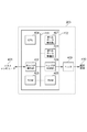
図1は、本発明の実施形態1に係る記録装置の構成の一例を示すブロック図である。
FIG. 1 is a block diagram showing an example of the configuration of a recording apparatus according to
本実施形態に係る記録装置200は、コントローラ402と、ヘッド410と、を備えており、外部のホストコンピュータ401と接続可能となっている。
The
コントローラ402は、記録装置200の制御を行う制御装置である。コントローラ402は、ROM403と、CPU404と、RAM405と、ホストIF制御部406と、第1のデータ処理部407と、ヘッドIF制御部408と、第2のデータ処理部409と、を備えている。また、これらは共有バス411で接続されている。この共有バス411を通じて、接続されたもの同士で通信が可能となる。
The
ROM403は、記録装置200を制御するためのプログラムを格納している読み出し可能なメモリである。CPU404は、ROM403に格納されたプログラムを実行することにより記録装置200の制御を行う。
The
RAM405は、プログラムの実行領域や画像データ等のデータの格納領域として使用される読み書き可能なメモリである。また、本実施形態に係るRAM405は、複数のバッファを有し、バッファ毎にメモリ領域が分割される構成になっており、画像データを格納する際に各バッファへ画像データの一部を複数のライン単位で分割して格納する。このため、一連の画像データは、バッファの境界でRAM405のメモリアドレス上で分割される。RAM405は、例えば、ホストデータ受信用バッファ、拡大処理参照用バッファ、拡大処理後格納用バッファ、低階調化処理用バッファを備えるものとし、バッファ単位で処理内容を独立させる。RAM405をこのような構成とすることにより、排他的にメモリアクセスすることが可能となり、全体の処理を効率よく実行することができる。なお、以下、バッファの先頭アドレスと最終アドレスを「メモリアドレスの境界」とし、参照アドレスを、あるバッファの最終アドレスから他方のバッファの先頭アドレスに切り替えることを「メモリアドレスの境界を跨ぐ」と記載する。また、RAM405内の複数のバッファを第1のメモリ領域、第2のメモリ領域と記載するが、異なるRAM405ではない。
The
ホストIF制御部406は、ホストコンピュータ401との通信を行い、印刷ジョブ等のデータの受信などを行い、受信したデータをRAM405へ格納する。本実施形態では、ホストIF制御部406が受信する印刷ジョブに含まれる画像データは、1画素がR,G,Bの3色で表され、1色の階調が8ビットである多階調の画像データ(以下、画像データ)とする。
The host
第1のデータ処理部407は、印刷ジョブに含まれる印刷条件に従ってRAM405に格納された画像データを変倍する処理を行う。本実施形態では、変倍処理として、画像データを拡大する処理を行う。第1のデータ処理部407で拡大された画像データは、RAM405へ格納される。
The first
第2のデータ処理部409は、印刷ジョブに含まれる印刷条件に従ってRAM405に格納された拡大された画像データから,インク色の画像データを生成する処理を行う。本実施形態では、多値のR,G,Bデータを多値のC(シアン),M(マゼンタ),Y(イエロー),K(ブラック)のインク色に変換して、インク色の画像データを生成する。さらに、インク色の画像データから記録装置200が印刷に用いる印刷可能な2値画像データを生成する低階調化処理を行い、生成された2値画像データはRAM405へ格納される。
The second
ヘッドIF制御部408は、RAM405に格納された2値画像データをヘッド410に出力する。
The head IF
ヘッド410は、2値画像データに基づいて被記録媒体420にインクを付与して画像を記録する。
The
ホストコンピュータ401は、印刷するために必要な画像データ情報や印刷条件情報を含む印刷ジョブの作成等を行う情報処理装置である。
The
本実施形態に係るシリアル型の記録装置(200)は、記録ヘッドが主走査方向に一定の速度で移動するキャリッジに搭載され、上記一定の速度に対応した周波数でインクを滴として吐出して記録用紙等の被記録媒体に印字する。1回の記録主走査が終了するごとに、被記録媒体は、主走査方向の垂直向きの副走査方向に所定の量だけ搬送される。このような記録主走査と搬送動作とを間欠的に繰り返すことにより、被記録媒体に段階的に画像が記録される。なお、記録ヘッドには、それぞれのインクを吐出するための複数の記録素子によって構成されている。コントローラ402は、このような動作を制御する。
The serial type recording apparatus (200) according to this embodiment is mounted on a carriage in which a recording head moves at a constant speed in the main scanning direction, and performs recording by ejecting ink as droplets at a frequency corresponding to the constant speed. Printing on a recording medium such as paper. Each time one main recording scan is completed, the recording medium is conveyed by a predetermined amount in the sub-scanning direction perpendicular to the main scanning direction. By intermittently repeating such recording main scanning and conveying operation, an image is recorded stepwise on the recording medium. The recording head is composed of a plurality of recording elements for ejecting each ink. The
ここで、第1のデータ処理部407の内部構成について詳細に説明する。
Here, the internal configuration of the first
本実施形態では、第1のデータ処理部407は、拡大処理を実行する際にはバイキュービック法により拡大処理を実行する。ここで、バイキュービックアルゴリズムによる拡大処理について簡単に説明する。バイキュービックアルゴリズムは、出力対象の画素を「着目画素」とした場合、その着目画素の位置を中心に周辺の16点(4×4マトリクス)の画素を参照して(以下、参照画素ともいう)、着目画素の画素値を決定するアルゴリズムである。この4×4マトリクスの参照画素の位置を着目画素に応じて移動させていくことで、元の画像データを拡大させることができる。すなわち、バイキュービックアルゴリズムでは、1ラインの画素を出力するために、4ラインの画素を参照する。
In the present embodiment, the first
図3は、拡大処理時のイメージを示した図である。本実施形態では、拡大率3倍で拡大処理を行う場合について説明する。図3に示す画像データイメージ501は、着目画素が参照する4×4マトリクスの参照画素の位置を示した図であり、画像データイメージ502は、参照画素を参照して拡大処理した際の拡大処理結果(出力結果)を示した図である。
FIG. 3 is a diagram showing an image at the time of enlargement processing. In the present embodiment, a case where enlargement processing is performed at an enlargement ratio of 3 will be described. An
拡大処理では、まず、着目画素の画素位置を決定し、それに対応した参照画素の位置を決定する。着目画素の画素位置とは、出力したい画素の位置を指す。本実施形態では、着目画素をライン単位とし、以下、ライン単位の着目画素を「着目ライン」又は「処理ライン」という。まず、画像データイメージ502のライン位置508を着目ラインとする。そして、着目ラインの位置(ライン位置508)が、画像データイメージ501のライン位置504と505の間であるため、参照する画素データのライン位置は503,504,505,506になる。すなわち、この4ライン(503,504,505,506)を参照して、1ライン(ライン位置508)の出力画素が生成されることになる。本実施形態では、拡大率が3倍であるため、画像データイメージ502のライン位置509の画素を着目画素とした場合及びライン位置510の画素を着目画素とした場合も同様に、画像データイメージ502のライン位置504と505の間である。したがって参照する画像データのライン位置は、ライン位置508の場合と同じとなる。次に、ライン位置511を着目ラインとした場合は、画像データイメージ501のライン505と506の間になるため、参照する画像データのライン位置は504,505,506,507になる。このようにして、処理する着目画素のライン位置に応じて、参照するライン位置が変わっていく。本実施形態では、バンド単位で処理を行うため、バンド内で参照ライン位置が更新されていく。なお、RAM405が上述した複数のバッファ構成であると、バンド処理の途中で参照するバッファが切り替わることから、着目ラインの位置によっては、参照ライン位置がメモリアドレスの境界を跨ぐことがある。
In the enlargement process, first, the pixel position of the pixel of interest is determined, and the position of the reference pixel corresponding thereto is determined. The pixel position of the target pixel indicates the position of the pixel to be output. In the present embodiment, the target pixel is set as a line unit, and the target pixel in the line unit is hereinafter referred to as a “target line” or a “processing line”. First, the
図2は、第1のデータ処理部407の内部構成を示すブロック図である。本実施形態では、拡大処理で参照する多値画像データが格納される複数のバッファを2つとし、その2つのバッファはそれぞれRAM405内の第1のメモリ領域602と第2のメモリ領域603とする。
FIG. 2 is a block diagram showing an internal configuration of the first
入力用DMAC101は、DMAC制御部105からの指示に従って、RAM405から参照する画像データ(入力データ)を読み出して、拡大処理部102へ供給するDMACである。拡大処理部102は、参照する画像データをバイキュービックアルゴリズムにより指定された倍率に拡大する処理を行い、生成された拡大後の画像データを出力用DMAC116へ送信する。出力用DMAC116は、拡大後の画像データ(出力データ)を共有バス411を介してRAM405へ書き込む。
The
拡大率格納部106は、拡大処理における倍率値(拡大率)を格納する。画像データ情報格納部107は、後述する処理バンドで処理を行う着目ライン位置の初期ライン位置を格納する。動作モード117には、拡大処理で用いる拡大アルゴリズムに応じたモードが設定される。本実施形態では、バイキュービックの動作モードが設定される。これらには、バンド処理を開始する前に、パラメータが設定される。
The enlargement
メモリ1の先頭アドレス格納部108は、着目ラインが第1のメモリ領域602におけるバンド内で参照する先頭画素のメモリアドレス値を格納する。メモリ1のライン数格納部110は、着目ラインが第1のメモリ領域602におけるバンド内で参照するライン数を格納する。メモリ2の先頭アドレス格納部109は、着目ラインが第2のメモリ領域におけるバンド内で参照する先頭画素のメモリアドレス値を格納する。メモリ2のライン数格納部111は、着目ラインが第2のメモリ領域におけるバンド内で参照するライン数を格納する。拡大率格納部106、画像データ情報格納部107、メモリ1の先頭アドレス格納部108、メモリ2の先頭アドレス格納部109、メモリ1のライン数格納部110、メモリ2のライン数格納部111は、バンド処理が開始される前にCPU404により設定される。
The start
処理ライン位置計算部103は、CPU404からバンド処理スタートの通知を受信すると、拡大率格納部106から拡大率を取得して、拡大処理を行う着目画素の位置(以下、着目ライン位置ともいう)を決定する。すなわち、バンド処理が開始すると、拡大率と処理を開始する着目画素の座標位置から処理するライン位置を算出する。
When the processing line
参照画像データ制御部104は、算出された着目ライン位置と、格納部108、109、110、111と、の情報に基づいて、画像データのいずれのライン位置を参照するかの情報を生成する。この参照画像データ制御部104は、着目ラインの位置に基づいて、参照する画像データの読み出しアドレスや読み出すライン数を決定する。具体的には、第1のメモリ領域602から読み出す先頭アドレス値をメモリ1の読み出しアドレス格納部112へ格納し、第1のメモリ領域602から読み出すライン数をメモリ1の読み出しライン数格納部114へ格納する。同様に、第2のメモリ領域603から読み出す先頭アドレス値をメモリ2の読み出しアドレス格納部113へ格納し、第2のメモリ領域603から読み出すライン数をメモリ2の読み出しライン数格納部115へ格納する。参照画像データ制御部104は、処理ライン位置が変更される度に、格納部112〜115の値を更新する。
The reference image
DMAC制御部105は、格納部112,113,114,115の情報に基づいて、入力用DMACに第1のメモリ領域602のいずれから何ラインを読み出すかを指示し、同様に第2のメモリ領域603のいずれから何ラインを読み出すかを指示する。このDMAC制御部105は、着目画素のライン位置(処理ライン位置)が変わるたびに、格納部112〜115の内容を取得し、それに基づき読み出し開始位置と読み出し量とをDMAC101へ設定し、DMAC101へ読み出しスタートを指示する。
The
図4は、本実施形態におけるバンド単位での拡大処理の説明図である。本実施形態では、多値画像データの一部である64ライン分の画像データ601を32ラインずつに分けて、それぞれRAM405の第1のメモリ領域602と第2のメモリ領域603に配置する。本実施形態では、拡大処理による拡大率は3倍(300%)とし、1バンドで出力するバンドライン数を16ラインとする。1バンドで出力するバンドライン数を16ライン固定として、複数のバンド単位で拡大処理をしていくと、次のバンドで参照する画像データの先頭ライン位置は、16ライン÷3倍=5.3ラインとなる。すなわち、次のバンドで参照する画像データの先頭ライン位置は、現在のバンドで参照する画像データの先頭ライン位置と比較して5ライン又は6ラインインクリメントする。したがって、拡大率が3倍の場合、バンド内のいずれのラインでバッファの境界(メモリアドレスの境界)を跨ぐことになるかは固定されない。すなわち、拡大率が3倍である場合、バッファを跨ぐ場合とバッファを跨がない場合があり、さらに、跨ぐ時のライン位置が毎回変わる。そのため、本実施形態のような拡大処理の処理位置を算出してその都度参照する画像データのライン位置を算出する必要がある。なお、1バンドで出力するバンドライン数が16ライン固定の場合、倍率が奇数であれば同様である。さらに言えば、16ライン固定ではない場合であっても、(出力バンドライン数)÷(拡大率)の値が整数ではない場合は、バンド内のどのラインでバッファの境界を跨ぐことになるかは固定されない。
FIG. 4 is an explanatory diagram of the enlargement process in band units in the present embodiment. In the present embodiment, 64-line image data 601 that is a part of multi-valued image data is divided into 32 lines and arranged in the
ここで、複数のバンドのうち処理バンド604を例に挙げて、バッファ境界におけるライン位置の拡大処理について説明する。処理バンド604が参照する画像データのライン数は、(出力ライン数÷倍率)+(各ラインの参照ライン数)−1で求められる。したがって、本実施形態では、16(ライン)÷3(倍)+4−1=8.3となり、処理バンド604内で参照するライン数は、切り上げた9ラインとなる。その9ラインうち、上の4ラインは第1のメモリ領域602に含まれるライン(605)で、下の5ラインは第2のメモリ領域603に含まれるライン(606)となる。すなわち、メモリアドレス上で連続していないのは、処理バンド604内の4ライン目と5ライン目となる。図4において、607は処理バンド604が第1のメモリ領域で参照するラインのうち先頭ラインの先頭画素のアドレスであり、以下、「処理バンド604の第1のメモリ領域の先頭画素アドレス」とする。また、608は処理バンド604が第2のメモリ領域で参照するラインのうち先頭ラインの先頭画素のアドレスであり、以下、「処理バンド604の第2のメモリ領域の先頭画素アドレス」とする。
Here, the process of enlarging the line position at the buffer boundary will be described using the
609はライン毎の左端画素のアドレスの差を示したアドレス値であり、以下、「ラインオフセット」とする。また、処理バンド604における着目ライン位置の初期ライン位置は、倍率が3倍であるため、図3の508、509、510を選択でき、いずれを選択してもよいが、本実施形態では初期ライン位置を508とする。
Reference numeral 609 denotes an address value indicating a difference in the address of the leftmost pixel for each line, and is hereinafter referred to as “line offset”. Further, since the magnification of the initial line position of the target line position in the
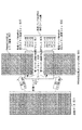
図5は、第1のデータ処理部407が拡大処理部102へデータ供給する際のライン管理に関する制御フローチャートを示す図である。図4の処理バンド604を拡大処理する際のデータフローを例に挙げて説明する。なお、本実施形態では、処理バンド604は、拡大倍率が3倍で、出力ライン数が16ラインであるため、拡大画像処理を16回行うことになる。
FIG. 5 is a diagram illustrating a control flowchart regarding line management when the first
まず、ステップS701で、CPU404により、データ処理部407内のレジスタ(106、107、108、109、110、111、116、117)の設定を行う。
First, in step S701, the
次に、ステップS702で、各レジスタ設定値をL1、L2、A1、A2、B、R、SBの内部パラメータへ反映させる。具体的には、L1へメモリ1のライン数格納部110のライン数を設定し、A1へメモリ1の先頭アドレス格納部108のアドレス値を設定する。L2へメモリ2のライン数格納部111のライン数を設定し、A2へメモリ2の先頭アドレス格納部109のアドレス値を設定する。Bへ画像出力ライン数格納部116のライン数をバンド出力ライン数として設定する。Rには、参照ライン数を設定する。本実施形態では、動作モードがバイキュービックアルゴリズムであるため参照ライン数として、Rには4ラインを設定する。SBへ画像データ情報格納部107の初期ライン位置である1ライン目を指定する。
Next, in step S702, each register set value is reflected on the internal parameters of L1, L2, A1, A2, B, R, and SB. Specifically, the number of lines of the line
ステップS703で、作業パラメータの初期化を行う。CA1は、DMAC開始時の第1のメモリ領域から読み出す先頭画素アドレスを示すパラメータであり、CA1の初期値としてA1の設定値を設定する。CA2は、DMAC開始時の第2のメモリ領域から読み出す先頭画素アドレスを示すパラメータであり、CA2の初期値としてA2の設定値を設定する。 In step S703, work parameters are initialized. CA1 is a parameter indicating a head pixel address read from the first memory area at the start of the DMAC, and a set value of A1 is set as an initial value of CA1. CA2 is a parameter indicating a head pixel address read from the second memory area at the start of DMAC, and a set value of A2 is set as an initial value of CA2.
ステップS704で、CPU404がバンド処理を開始する指示をする。
In step S704, the
ステップS705で、処理ライン位置計算部103に拡大処理を行う処理ラインの位置を計算させる。処理バンド604の最初の処理の場合、図4の処理バンド604内の1,2,3,4ライン目が参照ラインとなり、SBが1ライン目であることから、着目ライン位置は、処理バンド604内の2,3ライン目の間となる。バンド604内の1〜4ライン目が図3の503〜506に対応する場合、着目ラインの位置は、図3のライン位置508となる。
In step S705, the processing line
続いて、ステップS706で、参照画像データ制御部104が参照画像データのライン位置を更新するかを判定する。参照画像データのライン位置を更新する場合は、S707へ進み、参照画像データのライン位置を更新しない場合は、S725へ進む。ここでは、バンド処理の最初の処理であり更新が必要であるため、ステップS707へ進む。
In step S706, the reference image
ステップS707で、参照画像データ制御部104がL1のライン数がRのライン数以上であるかを判定する。Rのライン数以上ならばステップS708へ進み、Rのライン数に満たない場合はステップS710へ進む。ここでは、処理バンド604の最初の処理であるため、L1は4ラインでありRのライン数(4ライン)以上であるため、ステップS708へ進む。
In step S707, the reference image
ステップS708で、参照画像データ制御部104がメモリ1の読み出しライン数格納部114へRを設定する。ここでは、Rへ4ラインを設定する。ステップS709で、参照画像データ制御部104がメモリ2の読み出しライン数格納部115へ0ラインを設定する。続いて、ステップS712で、参照画像データ制御部104がメモリ1の読み出しアドレス格納部112へCA1を設定する。続いて、参照画像データ制御部104がメモリ2の読み出しアドレス格納部113へCA2を設定する。上述したS708〜S713により、DMACに設定するパラメータの生成を終える。
In step S <b> 708, the reference image
次に、次の参照画像データを更新する際のパラメータを準備する処理を行う。まず、ステップS714で、参照画像データ制御部104が、L1が1以上かを判定する。L1が1以上であればS715へ進み、L1が0であればS716へ進む。処理1回目では、L1は4ラインであるため、ステップS715へ進む。ステップS715で、参照画像データ制御部104がL1を1減算し、L1は3ラインとなり、ステップS717へ進む。ステップS717で、参照画像データ制御部104が、再度L1が1以上かを判定する。L1が1以上である場合はS718へ進み、L1が0の場合はS725へ進む。ここでは、L1は3ラインであるため、ステップS718へ進む。ステップS718で、参照画像データ制御部104が、A1にラインオフセットを加算したアドレス値をCA1に設定する。CA2は第2のメモリ領域から参照データを読み出すことがないため、更新をせずに、ステップS725へ進む。S714〜S718が、次回更新時のパラメータを準備するための処理フローになる。
Next, processing for preparing parameters for updating the next reference image data is performed. First, in step S714, the reference image
続いて、ステップS725で、DMAC制御部105により、メモリ1の読み出しアドレス格納部112、メモリ2の読み出しアドレス格納部113、メモリ1の読み出しライン数格納部114、メモリ2の読み出しライン数格納部115の設定値を取り出す。DMAC制御部105が設定値を取りだした後、その設定値を入力用DMAC101へ設定する。
Subsequently, in step S725, the
ステップS726で、DMAC制御部105が入力用DMAC101への設定が完了後、DMA転送の開始を入力用DMACへ通知し、入力用DMAC101は設定指示に従ってDMA転送を開始する。具体的には、DMAC101では、まず、第1のメモリ領域602から、メモリ1の読み出しアドレスから参照ラインの1ライン目の32画素分を32Byteのバースト転送で読み出す。続いて、メモリ1の読み出しアドレスにラインオフセット609を足したアドレスから参照ラインの2ライン目の32画素分を32Byteのバースト転送で読み出す。同様に、ラインオフセット609を用いて、3ライン目、4ライン目もメモリ1から読み出す。なお、本実施形態では、メモリからの読み出しはバースト転送により行ったが、これに限定されるものではない。4ライン目まで読み出すと、拡大処理部102に参照ラインの4ラインの左端の32画素分を供給できるようになり、拡大の画像処理が開始される。拡大された画像データは出力用DMAC116へ送信され、出力用DMAC116がこれをRAM405へ格納する。本実施形態では、32画素の3倍である96画素分出力されると、再度入力用DMAC101が先ほどの続きから4ライン分の32画素のデータを読み出し、拡大処理部102へ供給し、同様に画像処理を行う。このような処理を画像データの右端になるまで繰り返す。
In step S726, after the setting to the
ステップS727で、画像データの右端まで拡大処理が行われた後、DMAC制御部105は、拡大処理部102から画像処理終了の通知を受け、ステップS728へ進む。
In step S727, after the enlargement process is performed to the right end of the image data, the
ステップS728で、処理ライン位置計算部103がバンド処理の出力ライン数に達したかを判定する。バンド処理の出力ライン数に達した場合はS729へ進み、出力ライン数に達していない場合はS705へ戻る。出力ライン数は16ラインで、今は1ライン目であるため、ステップS705へ戻る。
In step S728, the processing line
以上が、処理バンド604の1回目の処理における制御フローとなる。
The above is the control flow in the first processing of the
続いて、処理バンド604の2回目の処理における制御フローを簡単に説明する。まず、ステップS705で、処理ライン位置計算部103が処理ライン位置を1ラインインクリメントし、処理ライン位置は、図3のライン位置509になる。ステップS706で、着目ライン位置509が図4の処理バンド内の2、3ライン目の間になり、上下2ラインの参照するライン位置と変わらないため、参照画像データのライン位置を変更する必要がないと判断し、ステップS725へ進む。ステップS725、S726、727では、1回目と同じ設定をDMAC101へ設定してDMA転送をスタートし、DMA転送を終了する。そして、ステップS728で、2回目の処理であるため、再び、ステップS705へ戻る。以上が、処理バンド604の2回目の処理における制御フローとなる。
Subsequently, a control flow in the second processing of the
なお、拡大率が3倍の場合は、3回に1度参照画像データのライン位置を更新すればよい。したがって、ステップS725で参照画像データのライン位置を更新しないと判定するのは、2回目の処理だけでなく、3回目、5回目、6回目、8回目、9回目、11回目、12回目、14回目、15回目も同様である。これらは、2回目の処理と同様のフローとなるため説明を省略する。 When the enlargement ratio is three times, the line position of the reference image data may be updated once every three times. Therefore, it is determined not to update the line position of the reference image data in step S725 in addition to the second process, but the third, fifth, sixth, eighth, ninth, eleventh, twelfth, 14th. The same applies to the 15th and 15th times. Since these are the same flow as the second processing, the description thereof is omitted.
続いて、処理バンド604の4回目の処理における制御フローを説明する。ステップS705で、処理ライン位置計算部103が処理ライン位置を1ラインインクリメントし、処理ラインの位置は、図3のライン位置511になる。すなわち、処理ラインの位置は、図4の処理バンド内の3,4ライン目の間となり、参照するライン位置が図4の処理バンド内の2,3,4,5ライン目となる。そのため、ステップS705で、参照画像データの読み出し情報を更新すること判断し、ステップS707へ進む。ステップS707で、L1は3ラインであるため、ステップS710へ進む。ステップS710で、参照画像データ制御部104がメモリ1の読み出しライン数格納部114へL1の3ラインを設定する。ステップS711で、参照画像データ制御部104がメモリ2の読み出しライン数格納部115へR−L1(ここでは、4ライン−3ライン)の1ラインを設定する。そして、ステップS712,S713で、参照画像データ制御部104がメモリ1の読み出しアドレス格納部112、メモリ2の読み出しアドレス格納部112へCA1とCA2をそれぞれ設定する。続いて、ステップS714からステップS718を経由してS728まで進む。ステップS728で、4回目の処理であるため、再び、ステップS705へ戻る。なお、バンド処理の7回目も同様のフローとなるため、説明を省略する。
Subsequently, a control flow in the fourth processing of the
次に、処理バンド604の10回目、13回目、16回目の処理について説明する。10回目、13回目、16回目の処理の場合、処理ラインの位置が参照ラインの2ライン目と3ライン目の間ではなくなるため、ステップS706で参照ラインの位置を更新すると判断し、ステップS707へ進む。
Next, the 10th, 13th, and 16th processes of the
まず、処理バンド604の10回目の処理における制御フローを説明する。10回目の処理では、ステップS707へ進んだ後、S710を経由してステップS717へ進む。ステップS717で、L1は、0ラインであるため、CA1及びCA2の更新をせずに、ステップS725を経由してステップS728へ進む。ステップS728で、10回目の処理であるためバンド処理の出力ライン数に達していないと判断し、再び、ステップS705へ戻る。つまり、次回の更新するタイミングであるバンド処理の13回目では、メモリ1からの参照データの読み出しが発生しないことになる。
First, a control flow in the 10th processing of the
処理バンド604の13回目及び16回目の処理では、ステップS707へ進んだ後、S710を経由してステップS714へ進む。ステップS714で、L1は、0ラインであるため、ステップS716へ進む。ステップS716で、L2が5ラインであるため、参照画像データ制御部104がL2のライン数を1減算してL2は4ラインとなる。ステップS723では、参照画像データ制御部104がCA2へA2にラインオフセットを加算したアドレス値を設定し、ステップS725を経由してステップS728へ進む。なお、CA1はL1が0ラインであるため、使用しないことから設定を更新しない。ステップS728で、10回目の処理のときは、バンド処理の出力ライン数に達していないと判断し、再び、ステップS705へ戻る。一方、16回目の処理では、処理回数が16回であり、出力ライン数に達したと判断し、ステップS729へ進む。ステップS729で、バンド処理が終了したことがCPU404へ通知され、CPU405がバンド処理を完了したことを検知する。
In the thirteenth and sixteenth processes of the
図6は、処理バンド604において、参照する画像データを処理する際にメモリから読み出すライン数及び読み出し時の先頭アドレスの位置を処理回数毎に整理した図である。ここで、第1のメモリ領域のライン数はL1に対応し、第2のメモリ領域のライン数はL2に対応する。
FIG. 6 is a diagram in which, in the
図6に示すように、拡大率が3倍であるため、バンド内の処理回数が1〜12回目の場合は、バンド内の処理回数が3の倍数のときに第1のメモリ領域の読み出し時の先頭アドレスの位置が変わる。そして、処理回数が13回目以降は、参照ラインがすべて第2のメモリ領域となる。本実施形態では、出力対象である着目ラインの位置を算出し、その着目ラインの位置に応じて参照すべきライン位置をメモリ領域毎に決定する。これにより、バンド内で参照画像データが2つのメモリ領域に分割されていても拡大処理部へデータを供給することができる。したがって、2つのメモリ領域の画像データを参照するような画像処理であっても、DMACを用いることにより、CPUが途中で介在することなく、バンド処理することが可能になる。また、メモリ上のデータコピーなどによるメモリ使用量を増大させることなく、バンド処理することが可能になる。すなわち、画像データを複数ラインずつに分割して複数のバンドを生成し、バンド毎に画像処理を実行する際に、DMACを用いることにより、CPUが途中で介在することなく複数ラインを一度に処理することが可能となる。また、無駄なメモリアクセスを抑制することができる。したがって、周辺画素を参照する画像処理において、より高速な画像処理を行うことができる。 As shown in FIG. 6, since the enlargement ratio is 3 times, when the number of times of processing in the band is 1 to 12, when the number of times of processing in the band is a multiple of 3, The position of the start address of. Then, after the 13th processing, all the reference lines become the second memory area. In this embodiment, the position of a target line that is an output target is calculated, and the line position to be referred to is determined for each memory area according to the position of the target line. Thereby, even if the reference image data is divided into two memory areas in the band, the data can be supplied to the enlargement processing unit. Therefore, even if the image processing refers to the image data in the two memory areas, the band processing can be performed without using the CPU in the middle by using the DMAC. In addition, band processing can be performed without increasing the amount of memory used by copying data on the memory. In other words, the image data is divided into a plurality of lines to generate a plurality of bands, and when performing image processing for each band, the DMAC is used to process a plurality of lines at a time without any CPU intervention. It becomes possible to do. Moreover, useless memory access can be suppressed. Therefore, faster image processing can be performed in image processing that refers to surrounding pixels.
(実施形態2)
図7〜9は、実施形態2に係る画像処理を説明する図である。本実施形態では、実施形態1と同様の部分については重複する説明は省略する。
(Embodiment 2)
7 to 9 are diagrams illustrating image processing according to the second embodiment. In the present embodiment, overlapping description of the same parts as those in the first embodiment will be omitted.
実施形態1では、メモリ領域(第1のメモリ領域602,第2のメモリ領域603)を跨ぐ画像データとして、図4の画像データ601のように連続した画像データを例に挙げて説明した。本実施形態では、さらに、オリジナルの画像データが全て白データというラインを含む場合、ホストコンピュータからそのラインを送信しない又はホストコンピュータとプリンタ間の転送帯域を下げる。
In the first embodiment, as the image data straddling the memory area (the
ここで、例えば、図7の画像データ901のように有効な画像データの間に白データ902が5ラインある場合について説明する。白データ902は実際にはメモリ領域に転送されてこないため、メモリ管理上は無効データが白データ902分存在することになる。例えば、メモリ管理上、第1のメモリ領域602の16ライン分の領域のうち、上9ラインが有効画像データで、中5ラインが無効データ903で、下2ラインが有効データ(905)として格納される。この有効データの参照ライン905を含んだ画像を処理する際、例えば、上2ラインを白データ、下2ラインを参照ライン905の2ラインとして、このうちの半分の有効な参照ライン905を参照して処理することが望まれる。そのような場合、上2ラインの白データをメモリ上から読み出すのではなく、画像処理内部で自動生成して白データを補完することで、読み出す参照ラインを2ラインとして効率的にデータを供給及び処理する。本実施形態では、画像データの上端や下端、すなわち、参照ラインが一部存在しない部分についても、白データの補完処理を行うことにより、バンド処理単位で拡大処理を行う。すなわち、補完処理による参照ライン数の読み出しライン数を可変に対応することができる。
Here, for example, a case where there are five lines of
例えば、図7の処理バンド904を拡大処理する場合、参照する画像データは7ラインあり、そのうち、上の2ラインは第1のメモリ領域(905)で、下の5ラインは第2のメモリ領域(906)になる。つまり、処理バンド904のメモリアドレス上連続していないのは、バンド内の2ライン目と3ライン目となる。 For example, when the processing band 904 in FIG. 7 is enlarged, there are 7 lines of image data to be referenced, of which the upper two lines are the first memory area (905) and the lower five lines are the second memory area. (906). That is, what is not continuous on the memory address of the processing band 904 is the second line and the third line in the band.
ここで、図7において、907は処理バンド904の第1のメモリ領域602の先頭画素アドレスであり、908は第2のメモリ領域603の先頭画素アドレスである。ラインオフセットは図4のラインオフセット609と同じである。また、拡大倍率が3倍であるため、処理バンド904における着目ライン位置において初期ライン位置を図3の508,509,510から選択できるが、本実施形態では、実施形態1と同様に初期ライン位置を508とする。また、処理バンド904が画像データの上端であるという情報を図1のCPU404が画像データ情報格納部107へバンド処理開始前に設定する。
Here, in FIG. 7, 907 is the leading pixel address of the
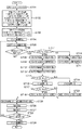
ライン管理に着目した制御フローを図8に示す。図8の制御フローは、図5の制御フローに、ステップS1001とS1002とS1003が追加されたものである。図8の制御フローでは、処理回数に応じて参照ライン数を増加させていくことで画像データの上端位置でのデータ供給を実現している。まず、ステップS701で、画像データの上端であることをCPUが設定し、ステップS702で、CPU404は、各レジスタ設定値をL1、L2、A1、A2、B、R、SBの内部パラメータへ反映させる。本実施形態では、L1、L2、A1、A2、B、SBは実施形態1と同様に設定するが、参照ライン数の初期値Rは、4ラインではなく、2ラインに設定する。ステップS1001では、通常時の参照ライン数、すなわち、白ラインが存在しない場合のライン数をR0に設定する。ここでは、バイキュービックアルゴリズムでの参照ラインを通常時の参照ラインとして、R0に4ラインを設定する。その後のS704〜S713までのフローは、図5と同じであるため説明を省略する。
A control flow focusing on line management is shown in FIG. The control flow in FIG. 8 is obtained by adding steps S1001, S1002, and S1003 to the control flow in FIG. In the control flow of FIG. 8, the data supply at the upper end position of the image data is realized by increasing the number of reference lines according to the number of processing times. First, in step S701, the CPU sets the upper end of the image data, and in step S702, the
ステップS1002で、参照画像データ制御部104は、現在の参照ライン数RがR0と同じであるかを判定し、RがR0に満たない場合はステップS1003に進み、R=R0の場合はステップS714へ進み、読み出すライン数やアドレスの更新処理を行う。ステップS1003では、参照画像データ制御部104が参照ラインRに対して1ライン加算する処理を行い、読み出すライン数やアドレスの更新の処理をスキップする。このようにして、ステップS706で参照画像データを更新すると判断される毎に参照ラインRのライン数をR0まで増やしていくことにより、画像データの上端で異なるメモリ間を跨ぐ場合でもデータを供給することができる。
In step S1002, the reference image
図9に、処理バンド904において、参照する画像データをメモリから読み出すためのライン数及び読み出し時の先頭アドレスの位置、有効データの参照ライン数及び補完ライン数を処理回数毎に整理した図を示す。図9に示すように、バンド内の処理回数がいずれの場合も、有効データの参照ライン数と補完ライン数の合計が4となる。ここで、参照ライン数は、各メモリ領域から読み込むライン数であり、補完ライン数とは、補完処理により生成される補完データのライン数である。 FIG. 9 is a diagram in which the number of lines for reading image data to be referred to from the memory, the position of the start address at the time of reading, the number of reference lines of valid data, and the number of complementary lines in the processing band 904 are arranged for each processing count. . As shown in FIG. 9, the sum of the number of reference lines and the number of complementary lines of valid data is 4 regardless of the number of processing times in the band. Here, the number of reference lines is the number of lines read from each memory area, and the number of complementary lines is the number of lines of complementary data generated by the complementary processing.
本実施形態では、上端に白データがある場合について説明したが、下端に白データがある場合も同様である。具体的には、画像データ情報格納部107に画像データの下端である情報を設定し、処理ライン位置に応じて参照ラインのRを徐々に減らしていくことで対応することができる。
In this embodiment, the case where there is white data at the upper end has been described, but the same applies when there is white data at the lower end. Specifically, this can be dealt with by setting information that is the lower end of the image data in the image data
本実施形態では、実施形態1と同様に、バンド内で参照画像データが2つのメモリ領域に分割されていても拡大処理部へデータを供給することができる。したがって、2つのメモリ領域の画像データを参照するような画像処理であっても、DMACを用いることにより、CPUによる途中介在や、メモリ上のデータコピーなどを行うことなく、バンド処理することが可能になる。 In the present embodiment, similarly to the first embodiment, data can be supplied to the enlargement processing unit even if the reference image data is divided into two memory areas within the band. Therefore, even with image processing that refers to image data in two memory areas, band processing can be performed without using intermediate processing by the CPU or copying data on the memory by using the DMAC. become.
また、本実施形態によれば、メモリ上に存在しない白データ(補完データ)を生成する場合であっても、DMACを用いることにより、CPUが途中で介在することなく、バンド処理することが可能になる。また、メモリ上のデータコピーなどによるメモリ使用量を増大させることなく、バンド処理することが可能になる。 Further, according to the present embodiment, even when white data (complementary data) that does not exist in the memory is generated, band processing can be performed without using the CPU in the middle by using the DMAC. become. In addition, band processing can be performed without increasing the amount of memory used by copying data on the memory.
(他の実施形態)
以上、本発明の各実施形態を説明したが、本発明の基本的構成は上述したものに限定されるものではない。例えば、上述した実施形態では、拡大処理の倍率を3倍としたが、拡大処理の倍率は特に限定されるものではない。なお、倍率を変更することにより、ステップS706での更新をする処理回数が変更され、また、倍率によっては、バッファを跨ぐときのライン位置が固定されることがある。
(Other embodiments)
As mentioned above, although each embodiment of this invention was described, the basic composition of this invention is not limited to what was mentioned above. For example, in the above-described embodiment, the magnification of the enlargement process is set to 3. However, the magnification of the enlargement process is not particularly limited. Note that by changing the magnification, the number of times of updating in step S706 is changed, and the line position when straddling the buffer may be fixed depending on the magnification.
上述した実施形態では、バンド内の拡大処理が1回につき拡大された画像データを1ラインずつ出力するものを例に挙げて説明したが、複数ライン同時に出力する場合も同様である。 In the above-described embodiment, an example has been described in which image data obtained by enlarging the band within one band is output line by line. However, the same applies to a case where a plurality of lines are output simultaneously.
また、上述した実施形態では、処理バンド604の初期ライン位置を3通りのうち1ライン目として説明したが、これに限定されるものではなく、2ライン目であっても3ライン目であってもよい。例えば、2ライン目であった場合、ステップ706で更新するタイミングがシフトされるだけであり、例えば、4回目で更新するのではなく、3回目で更新することになり、図6の結果に対して全体的に1処理分早くシフトされた結果となる。
In the above-described embodiment, the initial line position of the
また、上述した実施形態では、第1のデータ処理部407は、印刷ジョブに含まれる印刷条件に従ってRAM405に格納された画像データの拡大処理を行うものとしたが、縮小処理を行うものとしてもよい。この場合は、着目ラインの位置及び縮小率(変倍率)に基づいて、各メモリ領域から転送する入力データのライン数及びそのアドレスを決定するようにすればよい。
In the above-described embodiment, the first
上述した実施形態では、バッファの数を2つの場合を例に挙げて説明したが、1つのバンド処理で参照する画像データのメモリ領域を跨ぐようなメモリ配置であれば、本発明を適用可能である。すなわち、例えば、1つのバンド処理で参照する画像データが3以上のバッファを跨ぐようなメモリ配置であってもよく、バッファはリングバッファであってもよい。 In the embodiment described above, the case where the number of buffers is two has been described as an example. However, the present invention can be applied to any memory arrangement that straddles the memory area of the image data referred to in one band process. is there. That is, for example, the memory arrangement may be such that image data referred to in one band process straddles three or more buffers, and the buffer may be a ring buffer.
上述した実施形態では、複数のバッファをRAM405内に設ける構成としたが、RAMを複数個用意してそれぞれを1つのバッファとする構成であってもよい。
In the embodiment described above, a plurality of buffers are provided in the
上述した実施形態では、拡大処理のアルゴリズムとして4ラインを参照するバイキュービックを例に挙げて説明したが、これに限定されず、上下の画素を参照して処理を行うものであれば本発明を適用可能である。例えば、拡大処理のアルゴリズムとしてバイキュービックの代わりに2ラインを参照するバイリニアを用いてもよい。 In the above-described embodiment, the bicubic that refers to the four lines is described as an example of the enlargement processing algorithm. Applicable. For example, a bilinear that refers to two lines may be used instead of the bicubic as an enlargement processing algorithm.
上述した実施形態では、拡大処理を例にて説明したが、本発明に係る画像処理のデータ転送方法は、これに限定されるものではなく、上下の画素を参照して処理を行うものであり、メモリ領域を跨ぐことになるものであればよい。例えば、縮小処理やアンシャープマスクのような画像処理であってもよい。 In the above-described embodiment, the enlargement process has been described as an example. However, the data transfer method of the image processing according to the present invention is not limited to this, and the process is performed with reference to the upper and lower pixels. Any device that crosses the memory area may be used. For example, image processing such as reduction processing or unsharp masking may be used.
上述した実施形態では、画像処理の一例として拡大処理について説明したが、本発明は、これに限定されず、バンド間を跨ぐ画像処理の際には適用することができる。 In the above-described embodiment, the enlargement process has been described as an example of the image process. However, the present invention is not limited to this, and can be applied to an image process that spans between bands.
上述した実施形態では、インクジェットプリンタを例に挙げて説明したが、上下画素を参照する画像処理を備えていれば、本発明を適用することができる。したがって、画像形成装置は、インクジェットプリンタに限定されるものではなく、例えば、レーザプリンタや複写機のような印刷機であってもよく、ファクシミリ装置、携帯電話、PDA、画像ビューワー、デジタルカメラなどの他の画像形成装置であってもよい。 In the above-described embodiment, an inkjet printer has been described as an example. However, the present invention can be applied as long as image processing that refers to upper and lower pixels is provided. Accordingly, the image forming apparatus is not limited to an ink jet printer, and may be a printing machine such as a laser printer or a copying machine, such as a facsimile machine, a mobile phone, a PDA, an image viewer, a digital camera, or the like. Other image forming apparatuses may be used.
また、上述した実施形態の処理の全てをハードウェアで実行する必要はなく、一部をソフトウェアによって構成してもよい。 Also, it is not necessary to execute all of the processing of the above-described embodiment by hardware, and a part of the processing may be configured by software.
101 入力用DMAC
116 出力用DMAC
102 拡大処理部
103 処理ライン位置計算部
104 参照画像データ制御部
105 DMAC制御部
101 Input DMAC
116 Output DMAC
102
Claims (5)
前記処理部から出力される複数ラインからなる出力データのうち出力対象の着目ラインの位置を特定する特定手段と、
前記特定手段により特定された着目ラインの位置に応じて、前記第1のメモリ領域から転送する入力データのライン数及びそのアドレスを決定すると共に、前記第2のメモリ領域から転送する入力データのライン数及びそのアドレスを決定する決定手段と、
前記決定手段の決定に基づいて、前記第1のメモリ領域から所定のライン数の入力データを転送させると共に前記第2のメモリ領域から所定のライン数の入力データの転送を転送させるように制御する制御手段と、
を備えることを特徴とするデータ転送制御装置。 A data transfer control device for controlling transfer of input data comprising a plurality of lines stored across a plurality of memory areas including a first memory area and a second memory area to a processing unit,
Identifying means for identifying the position of the target line of output among the output data composed of a plurality of lines output from the processing unit;
The number of lines of input data transferred from the first memory area and its address are determined according to the position of the line of interest specified by the specifying means, and the line of input data transferred from the second memory area Determining means for determining the number and its address;
Based on the determination by the determination means, control is performed to transfer a predetermined number of lines of input data from the first memory area and to transfer a predetermined number of lines of input data from the second memory area. Control means;
A data transfer control device comprising:
前記決定手段の決定に基づいて、前記第1のメモリ領域から転送する入力データの先頭アドレスを特定する情報を格納する第2格納手段と、
前記決定手段の決定に基づいて、前記第2のメモリ領域から転送する入力データのライン数を特定する情報を格納する第3格納手段と、
前記決定手段の決定に基づいて、前記第2のメモリ領域から転送する入力データの先頭アドレスを特定する情報を格納する第4格納手段と、
前記特定手段により特定された着目ラインの位置に応じて、前記第1格納手段、前記第2格納手段、前記第3の格納手段、及び/又は前記第4の格納手段の更新を行う更新手段と、
を備えることを特徴とする請求項1に記載のデータ転送制御装置。 First storage means for storing information specifying the number of lines of input data transferred from the first memory area based on the determination by the determination means;
Second storage means for storing information for specifying a head address of input data transferred from the first memory area based on the determination by the determination means;
Third storage means for storing information specifying the number of lines of input data transferred from the second memory area based on the determination by the determination means;
Fourth storage means for storing information for identifying a head address of input data transferred from the second memory area based on the determination by the determination means;
Updating means for updating the first storage means, the second storage means, the third storage means, and / or the fourth storage means in accordance with the position of the line of interest specified by the specifying means; ,
The data transfer control device according to claim 1, further comprising:
前記特定手段は、前記取得手段により取得した情報と、前記特定手段により特定された着目ラインの位置に応じて、前記第1のメモリ領域から転送する入力データのライン数及び/又は前記第2のメモリ領域から転送する入力データのライン数を変更することを特徴とする請求項1〜3のいずれか一項に記載のデータ転送制御装置。 Obtaining means for obtaining information for identifying a line having no valid data in input data of a predetermined processing unit among the input data;
The specifying unit may determine the number of lines of input data transferred from the first memory area and / or the second line according to the information acquired by the acquiring unit and the position of the line of interest specified by the specifying unit. 4. The data transfer control device according to claim 1, wherein the number of lines of input data transferred from the memory area is changed.
前記処理部から出力される複数ラインからなる出力データのうち出力対象の着目ラインの位置を特定する特定工程と、
前記特定工程により特定された着目ラインの位置に応じて、前記第1のメモリ領域から転送する入力データのライン数及びそのアドレスを決定すると共に、前記第2のメモリ領域から転送する入力データのライン数及びそのアドレスを決定する決定工程と、
前記決定工程の決定に基づいて、前記第1のメモリ領域から所定のライン数の入力データを転送させると共に前記第2のメモリ領域から所定のライン数の入力データの転送を転送させるように制御する制御工程と、
を備えることを特徴とするデータ転送制御方法。
A data transfer control method for controlling transfer of input data composed of a plurality of lines stored across a plurality of memory areas including a first memory area and a second memory area to a processing unit,
A specifying step for specifying a position of a target line of output among output data consisting of a plurality of lines output from the processing unit;
The number of lines of input data transferred from the first memory area and the address thereof are determined according to the position of the line of interest specified in the specifying step, and the line of input data transferred from the second memory area A determining step for determining the number and its address;
Based on the determination in the determination step, control is performed to transfer a predetermined number of lines of input data from the first memory area and transfer a predetermined number of lines of input data from the second memory area. Control process;
A data transfer control method comprising:
Priority Applications (2)
| Application Number | Priority Date | Filing Date | Title |
|---|---|---|---|
| JP2013147907A JP2015022363A (en) | 2013-07-16 | 2013-07-16 | Data transfer controller, data transfer control method, and program |
| US14/330,994 US9036197B2 (en) | 2013-07-16 | 2014-07-14 | Data transfer control apparatus and data transfer control method |
Applications Claiming Priority (1)
| Application Number | Priority Date | Filing Date | Title |
|---|---|---|---|
| JP2013147907A JP2015022363A (en) | 2013-07-16 | 2013-07-16 | Data transfer controller, data transfer control method, and program |
Publications (2)
| Publication Number | Publication Date |
|---|---|
| JP2015022363A true JP2015022363A (en) | 2015-02-02 |
| JP2015022363A5 JP2015022363A5 (en) | 2016-08-04 |
Family
ID=52343373
Family Applications (1)
| Application Number | Title | Priority Date | Filing Date |
|---|---|---|---|
| JP2013147907A Pending JP2015022363A (en) | 2013-07-16 | 2013-07-16 | Data transfer controller, data transfer control method, and program |
Country Status (2)
| Country | Link |
|---|---|
| US (1) | US9036197B2 (en) |
| JP (1) | JP2015022363A (en) |
Families Citing this family (3)
| Publication number | Priority date | Publication date | Assignee | Title |
|---|---|---|---|---|
| CN104137063A (en) * | 2012-02-28 | 2014-11-05 | 株式会社安川电机 | Control apparatus and method for controlling control apparatus |
| JP6451175B2 (en) * | 2014-09-24 | 2019-01-16 | 富士ゼロックス株式会社 | Image processing apparatus, system, and program |
| JP2016103112A (en) * | 2014-11-27 | 2016-06-02 | 株式会社リコー | Data transfer control device, information processing device, and image forming apparatus |
Citations (5)
| Publication number | Priority date | Publication date | Assignee | Title |
|---|---|---|---|---|
| JPH05233795A (en) * | 1991-11-14 | 1993-09-10 | Matsushita Electric Ind Co Ltd | Image expansion/reduction device |
| JPH07244736A (en) * | 1994-03-04 | 1995-09-19 | Toshiba Corp | Pattern inspection device |
| JP2008140045A (en) * | 2006-11-30 | 2008-06-19 | Fuji Xerox Co Ltd | Image processor and image processing program |
| JP2010158810A (en) * | 2009-01-07 | 2010-07-22 | Canon Inc | Image processing apparatus, recording apparatus, and image processing method |
| JP2012025121A (en) * | 2010-07-27 | 2012-02-09 | Canon Inc | Data processor and data processing method |
Family Cites Families (3)
| Publication number | Priority date | Publication date | Assignee | Title |
|---|---|---|---|---|
| JPH08166921A (en) | 1994-12-12 | 1996-06-25 | Casio Comput Co Ltd | Direct memory access device and its data transfer system |
| US6746101B2 (en) * | 2000-09-27 | 2004-06-08 | Seiko Epson Corporation | Printing up to edges of printing paper without platen soiling |
| JP4848705B2 (en) * | 2005-08-19 | 2011-12-28 | セイコーエプソン株式会社 | Thermal printer, thermal printer control method and control program |
-
2013
- 2013-07-16 JP JP2013147907A patent/JP2015022363A/en active Pending
-
2014
- 2014-07-14 US US14/330,994 patent/US9036197B2/en not_active Expired - Fee Related
Patent Citations (5)
| Publication number | Priority date | Publication date | Assignee | Title |
|---|---|---|---|---|
| JPH05233795A (en) * | 1991-11-14 | 1993-09-10 | Matsushita Electric Ind Co Ltd | Image expansion/reduction device |
| JPH07244736A (en) * | 1994-03-04 | 1995-09-19 | Toshiba Corp | Pattern inspection device |
| JP2008140045A (en) * | 2006-11-30 | 2008-06-19 | Fuji Xerox Co Ltd | Image processor and image processing program |
| JP2010158810A (en) * | 2009-01-07 | 2010-07-22 | Canon Inc | Image processing apparatus, recording apparatus, and image processing method |
| JP2012025121A (en) * | 2010-07-27 | 2012-02-09 | Canon Inc | Data processor and data processing method |
Also Published As
| Publication number | Publication date |
|---|---|
| US20150022860A1 (en) | 2015-01-22 |
| US9036197B2 (en) | 2015-05-19 |
Similar Documents
| Publication | Publication Date | Title |
|---|---|---|
| JP2008148291A5 (en) | ||
| JP6128782B2 (en) | Image processing apparatus, image processing apparatus control method, program, and storage medium | |
| JP4725336B2 (en) | Image processing apparatus and image processing program | |
| US20120274989A1 (en) | Image processing apparatus, control method of image processing apparatus, and storage medium | |
| JP2008193529A (en) | Scanning converter, and scanning conversion method | |
| JP2015022363A (en) | Data transfer controller, data transfer control method, and program | |
| JP4930805B2 (en) | Print control program and print control apparatus | |
| JP5662675B2 (en) | Image forming apparatus and control method thereof | |
| JP4495048B2 (en) | Data transfer apparatus, operation display apparatus using the same, and image forming apparatus | |
| JP2012227598A (en) | Image processor, image forming apparatus, image processing method, image processing program and recording medium | |
| JP2007196567A (en) | Image forming method and image forming device | |
| JP2020110926A (en) | Image formation apparatus, control method of image formation apparatus, image formation system and program | |
| JP2008302661A (en) | Printing control device | |
| JP2010268411A (en) | Image processor, method of controlling the same, and program | |
| JP5202265B2 (en) | Image processing apparatus, program, and control method for image processing apparatus | |
| JP4232712B2 (en) | Image processing device | |
| JP4316476B2 (en) | Image processing apparatus and image forming apparatus | |
| JP6241670B2 (en) | Image processing device | |
| JP2005269502A (en) | Image processing apparatus and image processing method | |
| JP6155604B2 (en) | Image processing apparatus and image processing method | |
| JP5885780B2 (en) | Image processing apparatus, control method therefor, and program | |
| JP2009265776A (en) | Image processor | |
| JP2005153238A (en) | Printing controller and its method | |
| JP2008079036A (en) | Image processing apparatus | |
| JP2009154546A (en) | Image processing apparatus and image processing method |
Legal Events
| Date | Code | Title | Description |
|---|---|---|---|
| A521 | Request for written amendment filed |
Free format text: JAPANESE INTERMEDIATE CODE: A523 Effective date: 20160621 |
|
| A621 | Written request for application examination |
Free format text: JAPANESE INTERMEDIATE CODE: A621 Effective date: 20160621 |
|
| A131 | Notification of reasons for refusal |
Free format text: JAPANESE INTERMEDIATE CODE: A131 Effective date: 20170718 |
|
| A02 | Decision of refusal |
Free format text: JAPANESE INTERMEDIATE CODE: A02 Effective date: 20180403 |