JP2015019951A - Game machine - Google Patents
Game machine Download PDFInfo
- Publication number
- JP2015019951A JP2015019951A JP2013151857A JP2013151857A JP2015019951A JP 2015019951 A JP2015019951 A JP 2015019951A JP 2013151857 A JP2013151857 A JP 2013151857A JP 2013151857 A JP2013151857 A JP 2013151857A JP 2015019951 A JP2015019951 A JP 2015019951A
- Authority
- JP
- Japan
- Prior art keywords
- display
- effect
- time
- display means
- effective period
- Prior art date
- Legal status (The legal status is an assumption and is not a legal conclusion. Google has not performed a legal analysis and makes no representation as to the accuracy of the status listed.)
- Pending
Links
Images


Abstract
Description
本発明は、パチンコ機、アレンジボール機、スロットマシン等の遊技機に関するものである。 The present invention relates to a gaming machine such as a pachinko machine, an arrange ball machine, and a slot machine.
パチンコ機等の遊技機では、遊技者の遊技への関与意識を高めて興趣を増大させるため、発射ハンドル等とは別に例えば押しボタン式、その他の操作手段を1又は複数設け、図柄変動中等の操作有効期間中に遊技者がそれらの操作手段を操作することを条件に所定の演出を実行する、いわゆる操作演出の機能を搭載したものが多くなっている(例えば特許文献1)。 In a gaming machine such as a pachinko machine, in order to increase the interest of the player in the game and increase the interest, for example, one or more push button types other than the launch handle, etc. are provided, and other operation means are provided. Many of them are equipped with a so-called operation effect function that executes a predetermined effect on the condition that a player operates those operation means during the operation effective period (for example, Patent Document 1).
またこの種の遊技機では、操作有効期間中、遊技者に操作手段の操作を促す操作誘導表示を行うと共に、操作有効期間の残り時間(又は経過時間)を、例えばレベルゲージ(レベル表示手段)により減少(又は増加)表示することにより遊技者に報知するものも知られている。 Also, in this type of gaming machine, during the operation effective period, an operation guidance display that prompts the player to operate the operation means is performed, and the remaining time (or elapsed time) of the operation effective period is, for example, a level gauge (level display means) It is also known that a player is notified by displaying a decrease (or increase).
操作有効期間の長さは数秒程度と比較的短時間であるため、操作有効期間の残り時間(又は経過時間)のレベルゲージによる表示内容は遊技者が直感的に認識可能であることが望まれる。しかしながら、例えば操作有効期間が一定でない場合、操作有効期間の長さに応じてレベルゲージの長さ等を異ならせると、遊技者は操作有効期間がその全体に対してどの程度まで経過したかを直感的に認識することが難しく、混乱を生じさせてしまう可能性があった。 Since the operation effective period is a relatively short time of about several seconds, it is desirable that the player can intuitively recognize the content displayed by the level gauge of the remaining time (or elapsed time) of the operation effective period. . However, for example, when the operation effective period is not constant, if the length of the level gauge is varied according to the length of the operation effective period, the player can determine how much the operation effective period has elapsed with respect to the entire operation effective period. It was difficult to recognize intuitively and could cause confusion.
本発明は上記事情に鑑みてなされたものであり、操作有効期間の長さに拘わらず操作有効期間がその全体に対してどの程度まで経過したかを直感的に認識しやすくすることにより、操作手段を操作する遊技者に混乱を生じさせ難い遊技機を提供することを目的とする。 The present invention has been made in view of the above circumstances, and by making it easy to intuitively recognize how much the operation effective period has passed with respect to the entire operation regardless of the length of the operation effective period, It is an object of the present invention to provide a gaming machine that hardly causes confusion to a player who operates the means.
本発明は、外部から操作可能な操作手段12,13と、操作有効期間中に前記操作手段12,13が操作された場合に所定の演出を実行させる演出制御手段85と、前記操作有効期間の残り時間又は経過時間の減少又は増加に応じて、レベル表示領域53aに占めるレベル表示部53bの割合を減少又は増加させるレベル表示手段53とを備えた遊技機において、前記操作手段12,13を複数備え、前記演出制御手段85の制御により前記複数の操作手段12,13にそれぞれ対応する複数種類の前記演出を実行可能であり、前記レベル表示手段53による前記レベル表示領域53aは前記各演出に対応する前記操作有効期間の長さ及び前記操作手段12,13に拘わらず共通とし、前記レベル表示部53bの減少又は増加の速度を前記操作有効期間の長さに応じて異ならせたものである。
The present invention includes operation means 12 and 13 that can be operated from the outside, an effect control means 85 that executes a predetermined effect when the operation means 12 and 13 are operated during the operation effective period, and the operation effective period. In a gaming machine comprising level display means 53 for reducing or increasing the proportion of the
前記レベル表示領域53aに占める前記レベル表示部53bの割合が、前記操作有効期間の開始時に最大又は最小となり、前記操作有効期間の満了時に最小又は最大となるように構成してもよい。
The ratio of the
また、前記操作有効期間において前記操作手段12,13の操作を促す操作誘導表示を行う操作誘導表示手段51を備えた構成としてもよい。この場合、前記操作誘導表示手段51用の表示用データと前記レベル表示手段53用の表示用データとを個別に記憶する記憶手段92a,92b,92dを備え、前記操作誘導表示手段51と前記レベル表示手段53とがそれぞれ前記記憶手段92a,92b,92dから前記表示用データを読み出して表示するように構成してもよい。
Moreover, it is good also as a structure provided with the operation guidance display means 51 which performs the operation guidance display which prompts operation of the said operation means 12 and 13 in the said operation effective period. In this case, storage means 92a, 92b, and 92d for individually storing display data for the operation guide display means 51 and display data for the level display means 53 are provided, and the operation guide display means 51 and the level are provided. The
本発明によれば、操作有効期間の長さに拘わらず操作有効期間がその全体に対してどの程度まで経過したかを遊技者が直感的に認識しやすく、操作手段12,13を操作する遊技者に混乱を生じさせ難いという利点がある。 According to the present invention, it is easy for the player to intuitively recognize how much the operation effective period has elapsed with respect to the entire operation effective period regardless of the length of the operation effective period, and the game in which the operation means 12 and 13 are operated. There is an advantage that it is difficult to cause confusion.
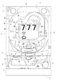
以下、本発明の実施形態を図面に基づいて詳述する。図1〜図17は本発明をパチンコ機に採用した第1の実施形態を例示している。図1において、遊技機本体1は、矩形状の外枠2と、この外枠2の前側に左右一側、例えば左側のヒンジ3により開閉自在に枢着された前枠4とを備えている。前枠4の前側には、ガラス扉5と前面板6とが上下に配置され、夫々ヒンジ3と同じ側のヒンジ7により前枠4に開閉自在に枢支されている。
Hereinafter, embodiments of the present invention will be described in detail with reference to the drawings. 1 to 17 illustrate a first embodiment in which the present invention is employed in a pachinko machine. In FIG. 1, a gaming machine
前面板6の前側には、図1及び図2に示すように、払い出し手段(図示省略)から払い出された遊技球を貯留して発射手段(図示省略)に供給する上皿8が上部側に配置され、またその上皿8の下側には、例えば上皿8が満杯のときにその余剰球を貯留する下皿9が左端側に、発射手段を作動させるための発射ハンドル10が右端側に夫々設けられている。更に、上皿8等を前側から覆う上皿カバー11上には、例えば左右方向の略中央に第1演出ボタン(操作手段)12が、左側に第2演出ボタン(操作手段)13が、右側に球貸し操作手段14が夫々配置されている。
As shown in FIGS. 1 and 2, on the front side of the
第1演出ボタン12は、遊技者の押圧操作を検出可能な押しボタン式の操作手段で、例えばドーム型の操作ボタン部15の内側に回転灯16が配置されており、操作ボタン部15が内部の弾性部材による付勢力に抗して押圧操作されたとき、その操作ボタン部15の移動によって内部の第1検出スイッチ(図示省略)がONに切り替わるように構成されている。この第1演出ボタン12は、後述する第1操作演出で用いられるもので、第1操作演出が開始されてその操作有効期間中に複数種類の操作態様(一回押し、連打等)のうちの指定操作態様で操作され、第1検出スイッチの検出状態がその指定操作態様に対応する操作成功条件を満たした場合に、例えば回転灯16を作動させる第1操作時演出が、利益状態の発生に関する信頼度等に応じた所定の確率で実行されるようになっている。
The
回転灯16は、1又は複数のLED17と、このLED17から発せられた光を回転軸に対する半径方向外向きに反射する回転反射板18とを備え、その外側が例えば着色透明の操作ボタン部15で覆われており、作動時にはLED17が点灯すると共に回転反射板18が回転するようになっている。また、例えばLED17は操作有効期間の報知手段を兼ねており、操作有効期間中にLED17が点灯又は点滅することによって第1演出ボタン12の操作が有効である旨を報知するようになっている。なお、このLED17が操作有効報知手段として作動する場合には例えば回転反射板18は回転せず、回転灯16が作動する回転灯作動演出と区別される。
The rotating
第2演出ボタン13は、遊技者の押圧操作を検出可能な押しボタン式の操作手段で、第1演出ボタン12の操作ボタン部15とは異なる形状、例えば平坦な略楕円形の操作ボタン部19を有し、操作ボタン部19が内部の弾性部材による付勢力に抗して押圧操作されたとき、その操作ボタン部19の移動によって内部の第2検出スイッチ(図示省略)がONに切り替わるように構成されている。この第2演出ボタン13は、後述する第2操作演出で用いられるもので、第2操作演出が開始されてその操作有効期間中に指定操作態様で操作され、第2検出スイッチの検出状態がその指定操作態様に対応する操作成功条件を満たした場合に、例えば画像表示手段20の背景色を変更する第2操作時演出が、利益状態の発生に関する信頼度等に応じた所定の確率で実行されるようになっている。
The
また、例えば操作ボタン部19の内部には、操作有効期間の報知手段として機能するLED21が1又は複数配置されており、操作有効期間中にLED21が点灯又は点滅することによって第2演出ボタン13の操作が有効である旨を報知するようになっている。
Further, for example, one or
また前枠4には、ガラス扉5の後側に対応して遊技盤31が着脱自在に装着されている。遊技盤31の前面側には、図1に示すように、発射手段から発射された遊技球を案内するガイドレール32が環状に装着されると共に、そのガイドレール32の内側の遊技領域33に、センターケース34、普通図柄始動手段35、特別図柄始動手段36、大入賞手段37、普通入賞手段38等の各種遊技部品が配置されている。
A
センターケース34には、液晶式等の画像表示手段20の他、普通図柄表示手段41、特別図柄表示手段42、普通保留個数表示手段43等が設けられている。画像表示手段20は、演出図柄表示手段45、特別保留個数表示手段46、操作有効期間表示手段47等を構成している。
The
普通図柄表示手段41は、普通図柄を変動表示するためのもので、例えば「○」「×」の2種類の普通図柄に対応する二つの発光体(例えばLED)により構成されており、通過ゲート等よりなる普通図柄始動手段35が遊技球を検出することを条件にそれら二つの発光体が所定時間交互に点滅して、普通図柄始動手段35による遊技球検出時に取得された当たり判定乱数値が予め定められた当たり判定値と一致する場合には当たり態様に対応する「○」側の発光体が発光した状態で、それ以外の場合には外れ態様に対応する「×」側の発光体が発光した状態で、点滅が終了するようになっている。 The normal symbol display means 41 is for variably displaying the normal symbol, and is composed of, for example, two light emitters (for example, LEDs) corresponding to two types of normal symbols “O” and “X”, and a passing gate. The two illuminants flash alternately for a predetermined time on the condition that the normal symbol starting means 35 detects the game ball, and the hit determination random number value acquired when the normal symbol starting means 35 detects the game ball is If it matches the predetermined hit determination value, the “◯” side illuminant corresponding to the hit mode is in a light-emitting state; otherwise, the “×” side illuminator corresponding to the detachment mode is set. The blinking ends when the light is emitted.
また、普通図柄表示手段41の変動表示中、又は後述する普通利益状態中に普通図柄始動手段35が遊技球を検出した場合には、その検出時に取得された当たり判定乱数値が予め定められた上限保留個数、例えば4個を限度として記憶されると共に、例えば上限保留個数と同数の発光体よりなる普通保留個数表示手段43がその発光個数により当たり判定乱数値の記憶個数(以下、普通保留個数という)を表示して、その時点での普通保留個数を遊技者に報知するようになっている。 Further, when the normal symbol starting means 35 detects a game ball during the fluctuation display of the normal symbol display means 41 or during the normal profit state described later, a hit determination random number value acquired at the time of detection is determined in advance. The upper limit number, for example, four is stored as a limit, and the normal number-of-holds display means 43 made up of, for example, the same number of light emitters as the upper limit number is used to determine the number of stored random number values for the hit determination (hereinafter referred to as the normal number of reservations). Is displayed, and the player is notified of the number of normally reserved items at that time.
特別図柄始動手段36は、特別図柄表示手段42による図柄変動を開始させるためのもので、上下二つの特別始動口36a,36bと、下特別始動口36bを開閉する開閉手段48とを備え、例えばセンターケース34の下側に配置されている。上特別始動口36aは、開閉手段等を有しない非作動式入賞口である。下特別始動口36bは、開閉手段48により遊技球が入賞可能な開状態と入賞不可能(又は開状態よりも入賞困難)な閉状態とに切り換え可能な作動式入賞口で、普通図柄表示手段41の変動後の停止図柄が当たり態様となって普通利益状態が発生したときに、開閉手段48が所定時間、所定回数だけ閉状態から開状態に変化するように構成されている。
The special symbol starting means 36 is for starting the symbol variation by the special symbol display means 42, and includes two upper and lower
特別図柄表示手段42は、1又は複数個の特別図柄を変動表示可能な7セグメント式等の表示手段により構成されており、特別図柄始動手段36が遊技球を検出すること、即ち上下二つの特別始動口36a,36bの何れかに遊技球が入賞することを条件に特別図柄を所定時間変動表示して、特別始動口36a,36bへの入賞時に取得された大当たり判定乱数値が予め定められた大当たり判定値と一致する場合には所定の大当たり態様で、それ以外の場合には外れ態様で停止するようになっている。特別図柄には、例えば大当たり態様及び外れ態様が夫々1又は複数種類ずつ設けられている。なお、それら各態様には夫々数字図柄等を割り当ててもよいし、遊技者がその特別図柄の種類を容易に区別できないように、任意の線や点の組み合わせのようなそれ自体としては特別な意味を持たない図柄を割り当ててもよい。
The special symbol display means 42 is constituted by a display means such as a seven-segment type capable of variably displaying one or a plurality of special symbols. The special symbol starting means 36 detects a game ball, that is, two special symbols on the upper and lower sides. A special symbol is variably displayed for a predetermined time on the condition that a game ball wins in either of the
また、特別図柄の変動表示中、又は後述する特別利益状態中に特別始動口36a,36bに遊技球が入賞した場合には、その入賞時に取得された大当たり判定乱数値等が夫々所定の上限保留個数、例えば各4個を限度として記憶されると共に、特別保留個数表示手段46が大当たり判定乱数値の記憶個数(以下、特別保留個数という)を表示して、その時点での特別保留個数を遊技者に報知するようになっている。 In addition, when a game ball wins a special start opening 36a, 36b during a special symbol variation display or a special profit state described later, the jackpot determination random number value obtained at the time of the winning is reserved for a predetermined upper limit. The number of pieces, for example, each four is stored as a limit, and the special reserved number display means 46 displays the stored number of the jackpot determination random number value (hereinafter referred to as special reserved number), and the special reserved number at that time is played. The person is notified.
演出図柄表示手段45は、例えば特別図柄表示手段42による特別図柄の変動表示と並行して演出図柄を変動表示するもので、1又は複数個、例えば左右方向に3個の演出図柄を例えば各種の演出画像と共に画像表示手段20の表示画面20aに変動表示可能に構成されており、特別図柄始動手段36が遊技球を検出すること、即ち上下二つの特別始動口36a,36bの何れかに遊技球が入賞することを条件に特別図柄の変動開始と同時に所定の変動パターンに従って演出図柄の変動を開始すると共に、特別図柄の変動停止と同時に最終停止するように、演出図柄を左、右、中等の所定の順序で停止させるようになっている。
The effect symbol display means 45 variably displays the effect symbols in parallel with, for example, the special symbol change display by the special symbol display means 42. For example, the effect symbol display means 45 displays one or more, for example, three effect symbols in the left-right direction. The
演出図柄には、例えば「0」〜「9」の10種類の数字図柄が用いられ、「6・6・6」「7・7・7」等、全ての図柄が同じ図柄で揃ったものが大当たり態様、少なくとも一つの図柄が異なるものが外れ態様となっている。なお、本実施形態では、特別図柄が大当たり態様となる場合には演出図柄も大当たり態様となり、特別図柄が外れ態様となる場合には演出図柄も外れ態様となるものとする。なお、演出図柄表示手段45は、特別図柄の変動内容とは直接関係のない演出を行う場合があってもよい。 For example, 10 kinds of numerical symbols from “0” to “9” are used for the production symbol, and all symbols such as “6, 6, 6”, “7, 7, 7”, etc. are arranged in the same pattern. The jackpot mode, at least one pattern is different from the other. In the present embodiment, when the special symbol is a jackpot mode, the effect symbol is also a jackpot mode, and when the special symbol is a miss mode, the effect symbol is also a miss mode. The effect symbol display means 45 may perform an effect that is not directly related to the variation content of the special symbol.
操作有効期間表示手段47は、後述する第1操作演出及び第2操作演出において、第1,第2演出ボタン12,13の少なくとも一つの操作が有効となる操作有効期間中にその操作有効期間に関する各種表示を行うもので、操作誘導表示手段51、第1残時間表示手段52、第2残時間表示手段53等を備えている。
The operation effective period display means 47 relates to an operation effective period during an operation effective period in which at least one operation of the first and
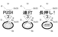
操作誘導表示手段51は、所定の操作手段(以下、指定操作手段という)を指定操作態様で操作することを遊技者に促すための操作誘導表示を行うもので、指定操作手段を示す指定操作手段報知画像を表示する指定操作手段表示手段51aと、指定操作態様を示す指定操作態様報知画像を表示する指定操作態様表示手段51bとで構成されている。 The operation guidance display means 51 performs an operation guidance display for prompting the player to operate a predetermined operation means (hereinafter referred to as a designated operation means) in a designated operation mode, and a designated operation means indicating the designated operation means. A designated operation means display means 51a for displaying a notification image and a specified operation mode display means 51b for displaying a specified operation mode notification image indicating a specified operation mode are configured.
本実施形態では、第1操作演出では第1演出ボタン12が、第2操作演出では第2演出ボタン13が指定操作手段として選択されるようになっている。指定操作手段表示手段51aによって表示される指定操作手段報知画像は、図15に示すように例えば指定操作手段の外観を表している。なお、複数の操作手段の操作が有効となる場合があってもよい。
In the present embodiment, the
また第1操作演出には、後述するように第1通常操作演出と第1特別操作演出との2種類があり、指定操作手段表示手段51aによって表示される指定操作手段報知画像はそれら第1通常操作演出と第1特別操作演出とで異なっている。本実施形態の指定操作手段表示手段51aは、第1通常操作演出と第1特別操作演出との何れの場合も指定操作手段である第1演出ボタン12の外観を表す指定操作手段報知画像を表示するが(図15(a)(b)参照)、その画像に表される第1演出ボタン12の状態が異なっており、第1通常操作演出の場合は例えば回転灯16が作動していない状態を示す画像(図15(a)参照)、第1特別操作演出の場合は例えば回転灯16が作動している状態を示す画像(図15(b)参照)となっている。
The first operation effect includes two types, a first normal operation effect and a first special operation effect, as will be described later. The designated operation means notification image displayed by the designated operation means display means 51a is the first normal action effect. The operation effect is different from the first special operation effect. The designated operation means display means 51a of the present embodiment displays a designated operation means notification image representing the appearance of the
また本実施形態では、「一回押し」、「連打」、「長押し」の3種類の操作態様が設けられており、それらのうちの何れかが指定操作態様として選択されるようになっている。「一回押し」は操作手段を1回だけ操作する操作態様で、例えば操作有効期間中に指定操作手段(例えば第1演出ボタン12)の検出スイッチがONになった時点で操作成功条件が満たされたと判断される。「連打」(第1操作態様)は操作手段を連続的に複数回操作する操作態様で、例えば操作有効期間中に指定操作手段の検出スイッチが2回以上の所定回数ONになった時点で操作成功条件が満たされたと判断される。「長押し」(第2操作態様)は操作手段を操作した状態を所定時間以上維持する操作態様で、例えば操作有効期間中に指定操作手段の検出スイッチがONとなってその状態が所定時間継続した時点で操作成功条件が満たされたと判断される。 In this embodiment, three types of operation modes of “single press”, “continuous hit”, and “long press” are provided, and any one of them is selected as the designated operation mode. Yes. “Press once” is an operation mode in which the operation means is operated only once. For example, the operation success condition is satisfied when the detection switch of the designated operation means (for example, the first effect button 12) is turned ON during the operation effective period. It is judged that it was done. “Sequential Strike” (first operation mode) is an operation mode in which the operation means is operated continuously several times. For example, the operation is performed when the detection switch of the designated operation means is turned ON a predetermined number of times or more during the operation valid period It is determined that the success condition has been met. “Long press” (second operation mode) is an operation mode in which the operating device is maintained in a state in which the operating device is operated for a predetermined time or more. At this point, it is determined that the operation success condition has been satisfied.
指定操作態様表示手段51bによって表示される指定操作態様報知画像は、図15に示すように例えば指定操作手段報知画像に向かう矢印画像と操作態様を示す文言画像とで構成されている。本実施形態では、「一回押し」、「連打」、「長押し」の3種類の操作態様を示す文言画像を、図15に示すようにそれぞれ「PUSH」、「連打」、「長押し!」としている。 As shown in FIG. 15, the designated operation mode notification image displayed by the designated operation mode display means 51b is composed of, for example, an arrow image directed to the designated operation means notification image and a word image indicating the operation mode. In the present embodiment, word images indicating three types of operation modes of “single press”, “continuous hit”, and “long press” are respectively displayed as “PUSH”, “continuous hit”, and “long press!” As shown in FIG. "
第1残時間表示手段(経過状況表示手段)52は、操作有効期間の残り時間(経過状況の一例)の目安を例えば数字で示す第1残時間報知画像を表示するものである。本実施形態の第1残時間表示手段52は、操作有効期間の残り時間を秒単位で表示し、操作有効期間の開始から満了までの時間経過に応じて「3」→「2」→「1」のようにその表示態様を段階的に変更するようになっている。なお、第1残時間表示手段52は、図15に示すように残り時間を示す第1残時間報知画像を例えば操作誘導表示手段51による操作誘導画像の一部に重なるようにその前側に表示するようになっている。 The first remaining time display means (elapsed status display means) 52 displays a first remaining time notification image that indicates, for example, a number indicating the remaining time of the operation effective period (an example of the elapsed status). The first remaining time display means 52 of the present embodiment displays the remaining time of the operation effective period in seconds, and “3” → “2” → “1” according to the elapsed time from the start of the operation effective period to the expiration. ", The display mode is changed step by step. The first remaining time display means 52 displays a first remaining time notification image indicating the remaining time as shown in FIG. 15, for example, on the front side so as to overlap a part of the operation guidance image by the operation guidance display means 51. It is like that.
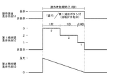
第2残時間表示手段(レベル表示手段)53は、操作有効期間の残り時間の目安を、レベル表示領域53aに占めるレベル表示部53bの割合によって表示するものである。本実施形態の第2残時間表示手段53は、一端側の最小位置と他端側の最大位置とが例えば上部側で一致するように楕円形の環状に形成されたレベル表示領域53aに沿って、その最小位置から最大位置に向けて例えば反時計方向に延びる帯状のレベル表示部53bを表示するようになっており、レベル表示領域53aの全周に占めるレベル表示部53bの割合が、操作有効期間の開始時に最大(例えば100%)となり、操作有効期間の満了時に最小(例えば0%)となるように、操作有効期間の開始から満了までの時間経過に応じてレベル表示部53bを一定速度で略無段階に(又は段階的に)減少表示するようになっている。
The second remaining time display means (level display means) 53 displays an indication of the remaining time of the operation effective period by the ratio of the
ここで、第2残時間表示手段53によるレベル表示領域53aは操作有効期間の長さに拘わらず共通であって、その形状、長さ、大きさ等は常に同じであり、レベル表示部53bの減少速度を操作有効期間の長さに応じて異ならせることで、操作有効期間の長さに拘わらず、操作有効期間の開始時に最大値を示した状態から減少表示が始まり、操作有効期間が経過した時点で最小値(0)に達するようになっている。また、レベル表示領域53aは、指定操作手段が異なる場合でも、操作誘導画像の種類、即ち操作演出や指定操作態様の種類が異なる場合についても共通に用いられる。
Here, the
なお、操作有効期間表示手段47の表示内容とLED17,21による報知内容はリンクしており、指定操作手段表示手段51aが第1演出ボタン12を示す場合には第1演出ボタン12のLED17が点灯又は点滅し、指定操作手段表示手段51aが第2演出ボタン13を示す場合には第2演出ボタン13のLED21が点灯又は点滅するようになっている。
The display contents of the operation valid period display means 47 and the notification contents by the
大入賞手段37は、遊技球が入賞可能な開状態と入賞不可能な閉状態とに切り換え可能な開閉板49を備えた作動式入賞手段で、特別図柄表示手段42の変動後の特別図柄が大当たり態様となって特別利益状態が発生したときに、開閉板49が所定の開放パターンに従って前側に開放して、その上に落下した遊技球を内部へと入賞させるようになっている。 The big winning means 37 is an actuating winning means having an opening / closing plate 49 that can be switched between an open state in which a game ball can be won and a closed state in which a game ball cannot be won. When the special profit state occurs in the big hit mode, the opening / closing plate 49 opens to the front side according to a predetermined opening pattern, and the game ball dropped on the opening plate 49 is awarded to the inside.
図3は本パチンコ機の制御系のブロック図である。図3において、54は主制御基板、55は演出制御基板で、これら各制御基板54,55は、遊技盤31に装着されたセンターケース34、その他の複数個の遊技部品を裏側から一括して覆う裏カバーの裏側等、前枠4及び遊技盤31を含む遊技機本体1の裏側の適宜箇所に着脱自在に装着された基板ケースに夫々収納されている。
FIG. 3 is a block diagram of the control system of the pachinko machine. In FIG. 3, 54 is a main control board, 55 is an effect control board, and each of these
主制御基板54は、主に遊技盤31側の遊技動作に関わる制御を行うためのもので、CPU,ROM,RAM等により構成される普通乱数作成処理手段61、普通始動口チェック処理手段62、普通乱数記憶手段63、普通図柄処理手段64、普通図柄表示制御手段65、普通利益状態発生手段66、特別乱数作成処理手段71、特別始動口チェック処理手段72、特別乱数記憶手段73、特別図柄処理手段74、特別図柄表示制御手段75、特別利益状態発生手段76、特別遊技状態発生手段77、制御コマンド送信手段78等を備えている。
The
普通乱数作成処理手段61は、変動後の普通図柄を当たり態様とするか否かの判定に用いる当たり判定乱数等を所定時間毎に繰り返し発生するように構成されている。普通始動口チェック処理手段62は、普通図柄始動手段35による遊技球の検出に基づく処理を行うもので、普通図柄始動手段35が遊技球を検出することに基づいて、普通乱数作成処理手段61で作成された当たり判定乱数値を1個取得し、その当たり判定乱数値を予め定められた上限保留個数(例えば4個)を限度として先入れ先出し式の普通乱数記憶手段63に記憶させるように構成されている。 The normal random number generation processing means 61 is configured to repeatedly generate a hit determination random number or the like used for determining whether or not the changed normal symbol is set to be a hit mode at predetermined time intervals. The normal start port check processing means 62 performs processing based on the detection of the game ball by the normal symbol start means 35. Based on the detection of the game ball by the normal symbol start means 35, the normal random number generation processing means 61 One hit determination random number value is obtained, and the hit determination random number value is stored in the first-in-first-out ordinary random number storage means 63 with a predetermined upper limit reserved number (for example, four) as a limit. Yes.
普通図柄処理手段64は、普通図柄の変動表示に関する処理を行うもので、普通図柄表示手段41が変動表示可能な状態となり且つ普通乱数記憶手段63に1個以上の当たり判定乱数値が記憶されていること(普通保留個数が1以上であること)を条件に、普通乱数記憶手段63に記憶されている当たり判定乱数値の待ち行列からその先頭の当たり判定乱数値を取り出し、その当たり判定乱数値が予め定められた当たり判定値と一致するか否かに応じて当たり/外れの判定を行う当たり判定機能、当たり/外れの判定結果に基づいて普通図柄の変動後の停止図柄の種類を選択する普通停止図柄選択機能、普通図柄の変動時間を選択する変動時間選択機能等を備えている。 The normal symbol processing means 64 performs processing related to the normal symbol fluctuation display. The normal symbol display means 41 is in a state capable of variable display, and one or more hit determination random number values are stored in the normal random number storage means 63. On the condition that the number of normal holdings is 1 or more, the first hit determination random number value is extracted from the queue of hit determination random number values stored in the normal random number storage means 63, and the hit determination random number value A hit determination function for determining hit / miss according to whether or not matches a predetermined hit determination value, and the type of stop symbol after fluctuation of the normal symbol is selected based on the hit / miss determination result A normal stop symbol selection function, a variable time selection function for selecting a normal symbol variation time, and the like are provided.
普通図柄表示制御手段65は、普通図柄処理手段64による普通図柄処理に基づいて普通図柄表示手段41の表示制御を行うもので、普通図柄表示手段41が変動表示可能な状態となり且つ普通乱数記憶手段63に1個以上の当たり判定乱数値が記憶されていること(普通保留個数が1以上であること)を条件に普通図柄表示手段41による普通図柄の変動を開始させ、普通図柄処理手段64で選択された変動時間が経過することに基づいて、同じく普通図柄処理手段64で選択された停止図柄で普通図柄の変動を停止させるようになっている。 The normal symbol display control means 65 controls the display of the normal symbol display means 41 based on the normal symbol processing by the normal symbol processing means 64. The normal symbol display means 41 is in a state in which the normal symbol display means 41 can be variably displayed and the normal random number storage means. 63, the normal symbol display means 41 starts to change the normal symbol on the condition that one or more hit determination random number values are stored in 63 (the number of normal holdings is 1 or more), and the normal symbol processing means 64 Based on the passage of the selected variation time, the variation of the normal symbol is stopped at the stop symbol selected by the normal symbol processing means 64.
普通利益状態発生手段66は、普通図柄処理手段64による判定結果が当たり判定となり、普通図柄表示手段41の変動後の停止図柄が当たり態様となったときに、特別図柄始動手段36を構成する下特別始動口36bの開閉手段48を例えば複数種類の開閉パターンの何れかに従って開状態に変化させるようになっている。
The normal profit state generating means 66 constitutes the special symbol starting means 36 when the result of determination by the normal symbol processing means 64 is a hit determination and the stop symbol after the fluctuation of the normal symbol display means 41 is in a hit state. The opening / closing means 48 of the
特別乱数作成処理手段71は、変動後の特別図柄を大当たり態様、外れ態様の何れにするかについての抽選に用いる大当たり判定乱数の他、変動後の特別図柄が大当たり態様となる場合の停止図柄の選択に用いる大当たり図柄乱数、変動後の特別図柄が外れ態様となる場合の停止図柄の選択に用いる外れ図柄乱数、演出図柄の変動パターンの選択に用いる変動パターン乱数、その他の所定の乱数を繰り返し発生する特別乱数作成処理を行うように構成されている。 The special random number creation processing means 71 is a jackpot determination random number used for the lottery to determine whether the special symbol after the change is to be the big hit mode or the off mode, as well as the stop symbol when the special symbol after the change becomes the big hit mode The jackpot symbol random number used for selection, the off symbol random number used for selection of the stop symbol when the special symbol after variation is out of mode, the variation pattern random number used for selecting the variation pattern of the production symbol, and other predetermined random numbers are repeatedly generated. It is configured to perform special random number generation processing.
特別始動口チェック処理手段72は、特別図柄始動手段36への遊技球の入賞に基づく処理を行うもので、特別図柄始動手段36が遊技球を検出すること、即ち特別始動口36a,36bの何れかに遊技球が入賞することに基づいて、特別乱数作成処理手段71で作成された大当たり判定乱数値及び大当たり図柄乱数値を1個ずつ取得し、それら大当たり判定乱数値及び大当たり図柄乱数値を予め定められた上限保留個数(例えば各4個)を限度として先入れ先出し式の特別乱数記憶手段73に記憶させるように構成されている。
The special start port check processing means 72 performs processing based on the winning of a game ball to the special symbol start means 36. The special symbol start means 36 detects a game ball, that is, any of the
特別図柄処理手段74は、特別図柄の変動表示に関する処理を行うもので、特別図柄表示手段42が変動表示可能な状態となり且つ特別乱数記憶手段73に1個以上の大当たり判定乱数値が記憶されていること(特別保留個数が1以上であること)を条件に、特別乱数記憶手段73に記憶されている大当たり判定乱数値の待ち行列からその先頭の大当たり判定乱数値を取り出し、その大当たり判定乱数値が予め定められた大当たり判定値と一致するか否かに応じて大当たり/外れ(抽選結果)の判定を行う大当たり判定機能、大当たり/外れの判定結果と、特別乱数記憶手段73に大当たり判定乱数値と共に記憶されている大当たり図柄乱数値又は新たに取得された外れ図柄乱数値とに基づいて、特別図柄の変動後の停止図柄を選択する特別停止図柄選択機能、大当たり/外れの判定結果と、新たに取得された変動パターン乱数値とに基づいて演出図柄の変動パターンを選択する変動パターン選択機能等を備えている。 The special symbol processing means 74 performs processing related to the special symbol fluctuation display. The special symbol display means 42 is in a state capable of variable display, and the special random number storage means 73 stores one or more jackpot determination random numbers. The jackpot determination random number value at the head is extracted from the queue of jackpot determination random number values stored in the special random number storage means 73, and the jackpot determination random number value is obtained. Jackpot determination function for determining jackpot / losing (lottery result) depending on whether or not matches a predetermined jackpot determination value, jackpot determination / losing determination result, and jackpot determination random number value in special random number storage means 73 A special symbol for selecting a stop symbol after the change of the special symbol based on the jackpot symbol random value stored together with the newly acquired symbol random value Stop symbol selection function, and the determination result of the jackpot / off, the change pattern selection function for selecting a variation pattern of performance symbols based on the newly acquired variation pattern random number.
特別図柄表示制御手段75は、特別図柄表示手段42の表示制御を行うもので、特別図柄処理手段74による特別図柄処理に基づいて、特別図柄表示手段42による特別図柄の変動を開始させると共に、選択された演出図柄の変動パターンに対応する変動時間が経過することに基づいて所定の停止図柄で特別図柄の変動を停止させるようになっている。 The special symbol display control means 75 controls the display of the special symbol display means 42. Based on the special symbol processing by the special symbol processing means 74, the special symbol display means 42 starts the change of the special symbol and is selected. The variation of the special symbol is stopped at a predetermined stop symbol based on the passage of the variation time corresponding to the variation pattern of the effected symbol.
特別利益状態発生手段(利益状態発生手段)76は、特別利益状態(利益状態)を発生させるためのもので、特別図柄処理手段74による大当たり/外れの判定結果(抽選結果)が大当たり判定となり、特別図柄表示手段42による特別図柄の変動後の停止図柄が大当たり態様となった場合に、大入賞手段37を所定の開放パターンに従って開放する特別利益状態を発生させるようになっている。本実施形態の開放パターンは、大入賞手段37の開放から所定時間(例えば28秒)経過するか、それまでに所定個数(例えば9個)の遊技球が入賞することを条件に大入賞手段37を閉鎖する動作を、所定ラウンド数(例えば15ラウンド)繰り返すように設定されているものとするが、複数種類の開放パターンを設け、例えば大当たり図柄乱数値に基づいてそれらの何れかを選択するように構成してもよい。 The special profit state generating means (profit state generating means) 76 is for generating a special profit state (profit state), and the jackpot / losing determination result (lottery result) by the special symbol processing means 74 is a jackpot determination. When the stop symbol after the special symbol is changed by the special symbol display means 42 becomes a big hit mode, a special profit state is generated in which the special winning means 37 is opened according to a predetermined release pattern. The opening pattern according to the present embodiment is based on the condition that a predetermined time (for example, 28 seconds) elapses from the opening of the large winning means 37 or that a predetermined number (for example, 9) of game balls have been won. Is set to repeat a predetermined number of rounds (for example, 15 rounds), but a plurality of types of opening patterns are provided, and for example, one of them is selected based on a jackpot symbol random number value. You may comprise.
特別遊技状態発生手段77は、特別利益状態発生後に遊技者に有利な特別遊技状態を発生させるためのもので、例えば特別乱数記憶手段73に記憶された大当たり判定乱数値が大当たり判定値と一致した場合の大当たり図柄乱数値に応じて、時短状態と確変状態との何れかの特別遊技状態を発生させるように構成されている。 The special game state generation means 77 is for generating a special game state advantageous to the player after the occurrence of the special profit state. For example, the jackpot determination random number value stored in the special random number storage means 73 matches the jackpot determination value. Depending on the jackpot symbol random value in the case, it is configured to generate a special game state of either a short time state or a probable variation state.
時短状態中は、特別図柄に関して特別図柄表示手段42の変動時間が通常変動時間よりも短い短縮変動時間に切り換えられる他、普通図柄に関して、当たり確率が通常確率(例えば1/10)から高確率(例えば1/1.3)へ、変動時間が通常変動時間(例えば27秒)から短縮変動時間(例えば2.7秒)へ、下特別始動口36bの開閉パターンが通常開閉パターン(例えば0.2秒×1回開放)から特別開閉パターン(例えば2秒×3回開放)へ、夫々切り換えられるようになっている。なお、時短状態は例えば特別利益状態の終了後に発生し、次の特別利益状態が発生するか、それまでに特別図柄が所定回数(例えば50回)変動した時点で終了する。
During the short time state, the variation time of the special symbol display means 42 is switched to a shortened variation time shorter than the normal variation time for the special symbol, and the hit probability for the normal symbol is a normal probability (eg, 1/10) to a high probability (for example, 1/10). For example, from 1 / 1.3), the fluctuation time is changed from a normal fluctuation time (for example, 27 seconds) to a shortened fluctuation time (for example, 2.7 seconds), and the opening / closing pattern of the lower
確変状態中は、それ以外の通常確率状態中よりも大当たり判定値の数が例えば1個から10個へ増加されることにより、特別図柄が大当たり態様となる確率が通常確率(例えば1/350)よりも高い高確率(例えば1/35)に切り換えられると共に、例えば時短状態と同様の処理も併せて行われるようになっている。なお、確変状態は例えば特別利益状態の終了後に発生し、次の特別利益状態が発生した時点で終了する。 During the probability variation state, the number of jackpot determination values is increased from 1 to 10, for example, compared to other normal probability states, so that the probability that the special symbol is a jackpot mode is a normal probability (for example, 1/350). Is switched to a higher probability (for example, 1/35) than that, and for example, processing similar to the time-short state is also performed. Note that the probability change state occurs, for example, after the special profit state ends, and ends when the next special profit state occurs.
制御コマンド送信手段78は、所定の制御コマンドを一方向通信により演出制御基板55等のサブ制御基板に送信して制御指令を与えるためのもので、特別図柄処理手段74による特別図柄処理に基づいて、特別図柄の変動開始時に、特別保留個数の減少を指定する保留減少コマンド、演出図柄の変動パターンを指定する変動パターンコマンド、特別図柄の停止図柄を指定する図柄指定コマンドをこの順序で演出制御基板55側に送信し、特別図柄の変動終了時に演出図柄の変動停止を指示する変動停止コマンドを演出制御基板55側に送信する機能、特別保留個数が増加したときに特別保留個数の増加を指定する保留増加コマンドを演出制御基板55側に送信する機能、特別遊技状態発生手段77による特別遊技状態の発生時及び終了時にその特別遊技状態に応じて特別遊技状態発生コマンド、特別遊技状態終了コマンド等を演出制御基板55側に送信する機能等を備えている。
The control command transmission means 78 is for transmitting a predetermined control command to a sub-control board such as the
演出制御基板55は、演出図柄表示手段45、特別保留個数表示手段46、操作有効期間表示手段47、回転灯16、音声出力手段81、電飾手段82等の各種演出手段を制御するためのもので、演出図柄制御手段83、特別保留個数表示制御手段84、操作演出制御手段85等を備えている。
The
演出図柄制御手段83は、演出図柄表示手段45の表示制御及びそれに伴う音声出力手段81、電飾手段82の制御を行うもので、主制御基板54から変動パターンコマンドを受信した場合に、指定された変動パターンに基づいて演出図柄表示手段45による演出図柄の変動及びそれに伴う音声出力、電飾発光を開始させると共に、変動停止コマンドを受信したときに、図柄指定コマンドと変動パターンコマンドとに基づいて選択された停止図柄で演出図柄の変動を停止させ、またそれに伴う音声出力、電飾発光を停止させるようになっている。
The effect symbol control means 83 controls the display of the effect symbol display means 45 and the accompanying voice output means 81 and the illumination means 82, and is designated when a variation pattern command is received from the
特別保留個数表示制御手段84は、特別保留個数表示手段46の表示制御を行うもので、特別図柄始動手段36により新たに遊技球が検出され、主制御基板54から保留増加コマンドを受信したときに、その保留増加コマンドに基づいて、画像表示手段20の表示画面20a上の所定位置に特別保留個数分の保留表示画像Xを表示し、例えば主制御基板54から保留減少コマンドを受信することに基づいて、表示中の保留表示画像Xの数を1個減少させて前側にシフトさせるように構成されている。
The special reserved number display control means 84 controls the display of the special reserved number display means 46, and when a new game ball is detected by the special symbol starting means 36 and a reserved increase command is received from the
操作演出制御手段(演出制御手段)85は、遊技者による所定操作を伴う操作演出を制御するもので、操作演出決定手段91、操作有効期間報知制御手段92、操作入力管理手段93、操作時演出制御手段94等を備えている。操作演出は、例えば特別図柄及び演出図柄の図柄変動毎に所定の確率で実行され、その操作演出中の所定の操作有効期間中に遊技者が指定操作手段を指定操作態様で操作した場合に、例えばその図柄変動の結果に応じて所定の確率で所定の操作時演出が実行されるようになっている。 The operation effect control means (effect control means) 85 controls an operation effect accompanied by a predetermined operation by the player. The operation effect determination means 91, the operation effective period notification control means 92, the operation input management means 93, and the operation effect. Control means 94 and the like are provided. The operation effect is executed at a predetermined probability for each symbol variation of the special symbol and the effect symbol, for example, and when the player operates the specified operation means in the specified operation mode during the predetermined operation valid period during the operation effect, For example, a predetermined operation effect is executed with a predetermined probability according to the result of the symbol variation.
本実施形態では、第1通常操作演出、第1特別操作演出及び第2操作演出の3種類の操作演出を実行可能であるとする。第1通常操作演出及び第1特別操作演出は、第1演出ボタン12を指定操作手段とする操作演出で、この第1通常操作演出中又は第1特別操作演出中における操作有効期間中に遊技者が第1演出ボタン12を指定操作態様で操作した場合に、1種類の操作時演出、例えば回転灯16を作動させる回転灯作動演出が、特別図柄の変動結果及び利益状態の種類等に応じた所定の確率で実行されるようになっている。
In the present embodiment, it is assumed that three types of operation effects can be executed: a first normal operation effect, a first special operation effect, and a second operation effect. The first normal operation effect and the first special operation effect are operation effects using the
一方、第2操作演出は、第2演出ボタン13を指定操作手段とする操作演出で、この第2操作演出中における操作有効期間中に遊技者が第2演出ボタン13を指定操作態様で操作した場合に、複数種類の操作時演出のうちの何れか、例えば画像表示手段20の背景色を青色に変更する「青背景演出」と赤色に変更する「赤背景演出」との何れかが、特別図柄の変動結果及び利益状態の種類等に応じた所定の確率で実行されるようになっている。
On the other hand, the second operation effect is an operation effect that uses the
操作演出決定手段91は、操作演出を実行するか否か、及び実行する場合にはその種類を特別図柄の図柄変動毎に決定するもので、例えば主制御基板54から変動パターンコマンド、図柄指定コマンドを受信することを条件に図8に示す操作演出決定処理を実行するように構成されている。即ち、操作演出決定手段91による操作演出決定処理は、特別図柄の変動開始毎に実行される。
The operation effect determining means 91 determines whether or not to execute the operation effect, and if so, the type of the operation effect for each symbol variation of the special symbol. For example, a variation pattern command, symbol designation command is sent from the
この操作演出決定処理(図8)では、まず操作演出を行うか否か、及び操作演出を行う場合にはその種類、即ち第1通常操作演出、第1特別操作演出、第2操作演出の何れかが例えば抽選により選択される(S1)。この抽選は例えば図4に示すような操作演出選択テーブルに基づいて行われる。図4に示す操作演出選択テーブルでは、第1通常操作演出、第1特別操作演出、第2操作演出、操作演出なしの4種類について、大当たり/外れの判定結果毎に選択率(%)が設定されている。 In this operation effect determination process (FIG. 8), first, whether or not an operation effect is to be performed, and when an operation effect is to be performed, any of the types, that is, the first normal operation effect, the first special operation effect, or the second operation effect. Is selected by lottery, for example (S1). This lottery is performed based on, for example, an operation effect selection table as shown in FIG. In the operation effect selection table shown in FIG. 4, the selection rate (%) is set for each determination result of big hit / loss for the four types of first normal operation effect, first special operation effect, second operation effect, and no operation effect. Has been.
この操作演出選択テーブル(図4)では、操作演出を行うか否かについては大当たり/外れの判定結果に拘わらず同じ選択率となっている。また、第1操作演出(第1通常操作演出及び第1特別操作演出)と第2操作演出との選択率についても大当たり/外れの判定結果に拘わらず一定で、第1操作演出よりも第2操作演出の方が選択率が高くなっている。即ち、操作演出が行われる場合と行われない場合とで大当たり期待度に差はなく、また第1操作演出が行われる場合と第2操作演出が行われる場合とについても大当たり期待度に差はない。 In this operation effect selection table (FIG. 4), whether or not to perform the operation effect is the same selection rate regardless of the determination result of jackpot / losing. Further, the selection rate between the first operation effect (the first normal operation effect and the first special operation effect) and the second operation effect is constant regardless of the determination result of the big hit / losing, and is second than the first operation effect. The selection rate is higher in the operation direction. That is, there is no difference in the jackpot expectation between when the operation effect is performed and when it is not performed, and there is no difference in the jackpot expectation when the first operation effect is performed and when the second operation effect is performed. Absent.
一方、第1通常操作演出と第1特別操作演出との選択率については、外れ判定の場合には第1通常操作演出の方が高いのに対し、大当たり判定の場合には逆に第1特別操作演出の方が高くなっている。即ち、第1操作演出が行われる場合、それが第1通常操作演出である場合(後述する通常操作誘導表示が出現する場合)よりも第1特別操作演出である場合(後述する特別操作誘導表示が出現する場合)の方が大当たり期待度(利益状態が発生する確率)が高くなっている。 On the other hand, with respect to the selection rate between the first normal operation effect and the first special operation effect, the first normal operation effect is higher in the case of the determination of losing, whereas the first special operation effect is reverse in the case of the jackpot determination. Operation direction is higher. That is, when the first operation effect is performed, when it is the first special operation effect than when it is the first normal operation effect (when a normal operation guide display described later appears) (special operation guide display described later). The probability of jackpot expectation (the probability that a profit state will occur) is higher in the case of
なお、操作演出を行うか否か及び操作演出の種類については抽選以外の方法で決定してもよい。例えば演出図柄の変動パターン毎に、操作演出を行うか否か及び操作演出の種類を予め設定しておいてもよいし、演出図柄の変動パターン毎に操作演出の種類を予め設定しておき、操作演出を行うか否かについては抽選により決定するようにしてもよい。S1において操作演出を行わない旨の決定がされた場合には(S2:No)、ここで操作演出決定処理は終了する。 Note that whether or not to perform an operation effect and the type of operation effect may be determined by a method other than lottery. For example, whether or not to perform an operation effect and the type of operation effect may be set in advance for each variation pattern of the effect symbol, or the type of operation effect may be set in advance for each variation pattern of the effect symbol, Whether or not to perform the operation effect may be determined by lottery. When it is determined in S1 that the operation effect is not performed (S2: No), the operation effect determination process ends here.
S1において操作演出を行う旨の決定がされた場合には(S2:Yes)、続いて指定操作態様として例えば「一回押し」、「連打」、「長押し」の何れかが例えば抽選により選択される(S3)。なお指定操作態様についても、例えば演出図柄の変動パターン毎に予め指定操作態様を設定しておくなど、抽選以外の方法で決定してもよい。 If it is determined in S1 that an operation effect is to be performed (S2: Yes), then, for example, one of “single press”, “continuous hit”, and “long press” is selected by lottery, for example, as the designated operation mode (S3). Note that the designated operation mode may be determined by a method other than the lottery, for example, by setting the designated operation mode in advance for each variation pattern of the effect symbols.
また、操作有効期間の長さ(以下、操作有効時間という)及び開始タイミングが例えば抽選により決定される(S4)。操作有効時間及び操作有効期間の開始タイミングは、演出図柄の変動パターンにおける変動時間、S3で選択された指定操作態様等に基づいて決定することが望ましい。 Further, the length of the operation effective period (hereinafter referred to as operation effective time) and the start timing are determined, for example, by lottery (S4). It is desirable to determine the operation effective time and the start timing of the operation effective period based on the change time in the change pattern of the effect design, the designated operation mode selected in S3, and the like.
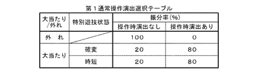
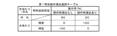
また、操作演出の種類に応じて(S5)操作時演出の有無、内容等が決定される(S6〜S14)。S5において操作演出が第1通常操作演出であると判定された場合には例えば図5に示すような第1通常操作演出選択テーブルに基づいて、また第1特別操作演出であると判定された場合には例えば図6に示すような第1特別操作演出選択テーブルに基づいて、それぞれ例えば操作時演出の有無が決定される(S6,S7)。第1通常操作演出選択テーブル(図5)及び第1特別操作演出選択テーブル(図6)では、遊技者の操作があったときに操作時演出を行うか否かについて、大当たりで且つ確変状態発生(以下、確変大当たりという)、大当たりで且つ時短状態発生(以下、時短大当たりという)、外れの各判定結果毎に選択率(%)が設定されている。 Further, depending on the type of operation effect (S5), the presence / absence, content, etc. of the operation effect are determined (S6 to S14). When it is determined in S5 that the operation effect is the first normal operation effect, for example, based on the first normal operation effect selection table as shown in FIG. 5 and when it is determined that the operation effect is the first special operation effect. For example, based on the first special operation effect selection table as shown in FIG. 6, for example, the presence / absence of the operation effect is determined (S6, S7). In the first normal operation effect selection table (FIG. 5) and the first special operation effect selection table (FIG. 6), whether or not the operation effect is performed when the player operates is a big hit and a probable change state occurs. A selection rate (%) is set for each determination result (hereinafter referred to as “probability big hit”), big hit and time-short state occurrence (hereinafter referred to as “time-short big hit”), and out of place.
図5に示す第1通常操作演出選択テーブルでは、外れの場合には操作時演出ありの選択率が0%となっているため、第1通常操作演出において遊技者の操作時に操作時演出が行われた場合には大当たりとなることが確定する。また、確変大当たりの場合と時短大当たりの場合とで操作時演出の有無についての選択率に違いはなく、従って第1通常操作演出において遊技者の操作時に操作時演出が行われる場合と行われない場合とで大当たりとなった場合の確変期待度に差はない。 In the first normal operation effect selection table shown in FIG. 5, since the selection rate with the operation effect is 0% in the case of detachment, the operation effect is performed when the player operates in the first normal operation effect. If it is broken, it will be a big hit. Also, there is no difference in the selection rate for the presence or absence of the operation-time effect between the probability variation jackpot and the time-saving jackpot, and therefore the operation-time effect is not performed when the player operates in the first normal operation effect. There is no difference in the expected probability of change when the jackpot is large.
一方、図6に示す第1特別操作演出選択テーブルでは、外れの場合には操作演出ありよりも操作演出なしの方が選択率が高くなっている。また、確変大当たりの場合には操作時演出ありの選択率が100%であるのに対し、時短大当たりの場合には操作時演出なしの選択率が100%となっている。即ち、第1特別操作演出においては、遊技者の操作時に操作時演出が行われた場合には、大当たりになるとすればそれが確変大当たりであることが確定する。 On the other hand, in the first special operation effect selection table shown in FIG. 6, in the case of detachment, the selection rate is higher without the operation effect than with the operation effect. In addition, in the case of a promising big hit, the selection rate with an effect at the time of operation is 100%, whereas in the case of a time bonus, the selection rate without an effect at the time of operation is 100%. In other words, in the first special operation effect, if the operation effect is performed at the time of the player's operation, if it is a big hit, it is determined that it is a promising big hit.
そして、S6又はS7において操作時演出ありが選択された場合には、第1操作時演出フラグに操作時演出ありに対応する「1」がセットされ(S9)、操作時演出なしが選択された場合には、第1操作時演出フラグに操作時演出なしに対応する「0」がセットされる(S10)。 Then, when “with operation effect” is selected in S6 or S7, “1” corresponding to “with operation effect” is set in the first operation effect flag (S9), and “without operation effect” is selected. In this case, “0” corresponding to no operation time effect is set in the first operation time effect flag (S10).
S5において操作演出が第2操作演出であると判定された場合には、例えば図7に示すような第2操作演出選択テーブルに基づいて例えば操作時演出の種類(ここでは青背景演出又は赤背景演出)が決定される(S11)。第2操作演出選択テーブル(図7)では、各操作時演出(ここでは青背景演出又は赤背景演出)について、確変大当たり、時短大当たり、外れの各判定結果毎に選択率(%)が設定されている。 If it is determined in S5 that the operation effect is the second operation effect, for example, based on the second operation effect selection table as shown in FIG. 7, for example, the type of operation effect (here, blue background effect or red background) (Production) is determined (S11). In the second operation effect selection table (FIG. 7), for each operation effect (here, the blue background effect or the red background effect), a selection rate (%) is set for each determination result of probability variation big win, time junior big hit, and off. ing.
図7に示す第2操作演出選択テーブルでは、外れの場合には赤背景演出よりも青背景演出の方が選択率が高いのに対し、大当たりの場合には逆に青背景演出よりも赤背景演出の方が選択率が高くなっている。即ち、第2操作時演出においては、遊技者の操作時に青背景演出が行われる場合よりも赤背景演出が行われる場合の方が大当たり期待度は高い。また、時短大当たりの場合よりも確変大当たりの場合の方が赤背景演出の選択率が高くなっている。即ち、第2操作時演出においては、遊技者の操作時に青背景演出が行われる場合よりも赤背景演出が行われる場合の方が大当たりとなった場合の確変期待度は高い。 In the second operation effect selection table shown in FIG. 7, the blue background effect has a higher selection rate than the red background effect in the case of losing, whereas the red background rather than the blue background effect in the case of a big hit. The selection rate is higher for production. That is, in the second operation effect, the expectation of jackpot is higher when the red background effect is performed than when the blue background effect is performed during the player's operation. In addition, the selection ratio of the red background effect is higher in the case of the probability variation jackpot than in the case of the time bonus. That is, in the second operation time effect, the probability variation expectation is higher when the red background effect is a big hit than when the blue background effect is performed during the player's operation.
そして、S11において赤背景演出が選択された場合には、第2操作時演出フラグに赤背景演出に対応する「1」がセットされ(S13)、青背景演出が選択された場合には、第2操作時演出フラグに青背景演出に対応する「0」がセットされる(S14)。 When the red background effect is selected in S11, “1” corresponding to the red background effect is set in the second operation time effect flag (S13), and when the blue background effect is selected, “0” corresponding to the blue background effect is set in the two-operation effect flag (S14).
操作有効期間報知制御手段92は、操作有効期間の報知に関する制御を行うもので、例えば指定操作手段表示手段51a、指定操作態様表示手段51b、第1残時間表示手段52、第2残時間表示手段53による表示用の画像データ(表示用データ)がそれぞれ格納された第1〜第4記憶手段92a〜92dを備えており、図9に示す操作有効期間報知制御処理を、例えば定期割り込みにより所定時間間隔(ここでは4ms間隔)で実行するようになっている。
The operation effective period notification control unit 92 performs control related to notification of the operation effective period. For example, the specified operation
この操作有効期間報知制御処理(図9)では、まず操作有効期間中であるか否かが判定される(S21)。そして、操作有効期間中でないと判定された場合には(S21:No)、S4で決定された操作有効期間の開始タイミングが到来したか否かが判定され(S22)、操作有効期間の開始タイミングが到来したと判定されることを条件に(S22:Yes)、例えば図10に示すような操作有効期間報知開始処理(S23)が行われる。 In this operation valid period notification control process (FIG. 9), it is first determined whether or not the operation valid period is in effect (S21). If it is determined that the operation effective period is not in effect (S21: No), it is determined whether or not the operation effective period start timing determined in S4 has arrived (S22), and the operation effective period start timing is determined. On the condition that it is determined that has arrived (S22: Yes), for example, an operation valid period notification start process (S23) as shown in FIG. 10 is performed.
操作有効期間報知開始処理(図10)では、まずS1で選択された操作演出の種類に基づいて、指定操作手段表示手段51aによって表示される指定操作手段報知画像が設定される(S31)。例えば、第1通常操作演出の場合には図15(a)に示すような回転灯停止中の第1演出ボタン12を表した指定操作手段報知画像が、第1特別操作演出の場合には図15(b)に示すような回転灯作動中の第1演出ボタン12を表した指定操作手段報知画像が、第2操作演出の場合には図15(c)に示すような第2演出ボタン13を表した指定操作手段報知画像がそれぞれ設定される。指定操作手段報知画像の画像データは、第1記憶手段92aに予め記憶されている。
In the operation valid period notification start process (FIG. 10), first, based on the type of operation effect selected in S1, a specified operation means notification image displayed by the specified operation means display means 51a is set (S31). For example, in the case of the first normal operation effect, the designated operation means notification image representing the
なお、回転灯停止中の第1演出ボタン12を表した指定操作手段報知画像が通常操作誘導表示の一例であり、回転灯作動中の第1演出ボタン12を表した指定操作手段報知画像が特別操作誘導表示の一例である。
The designated operation means notification image representing the
また、S3で選択された指定操作態様に基づいて、指定操作態様表示手段51bによって表示される指定操作態様報知画像が設定される(S32)。例えば、「一回押し」の場合には図15(a)に示すような「PUSH」の文字を表した指定操作態様報知画像が、「連打」の場合には図15(b)に示すような「連打」の文字を表した指定操作態様報知画像が、「長押し」の場合には図15(c)に示すような「長押し!」の文字を表した指定操作態様報知画像がそれぞれ設定される。指定操作態様報知画像の画像データは、第2記憶手段92bに予め記憶されている。 Also, based on the designated operation mode selected in S3, the designated operation mode notification image displayed by the designated operation mode display means 51b is set (S32). For example, in the case of “press once”, the designated operation mode notification image representing the characters “PUSH” as shown in FIG. 15A is shown in FIG. In the case where the designated operation mode notification image representing the character “long hit” is “long press”, the designated operation mode notification image representing the character “long press!” As shown in FIG. Is set. The image data of the designated operation mode notification image is stored in advance in the second storage unit 92b.
また、例えば図11に示すような第1残時間報知設定処理(S33)が行われる。この第1残時間報知設定処理(図11)では、操作有効時間に端数があるか否か(操作有効期間が、その長さを所定単位時間で割ったときに余り時間が生じる第1操作有効期間であるか否か)が判定される(S41)。この端数は、操作有効時間を所定単位時間で割ったときに生じる余り時間である。本実施形態では、所定単位時間を1秒としているため、操作有効時間を秒で表した場合の小数点以下の部分、例えば操作有効時間が2.4秒であれば0.4秒が端数(余り時間)となる。 Further, for example, a first remaining time notification setting process (S33) as shown in FIG. 11 is performed. In the first remaining time notification setting process (FIG. 11), whether or not there is a fraction in the operation effective time (the operation effective period is the first operation effective time that occurs when the length is divided by the predetermined unit time). It is determined whether it is a period (S41). This fraction is a surplus time generated when the operation effective time is divided by a predetermined unit time. In this embodiment, since the predetermined unit time is 1 second, when the operation effective time is expressed in seconds, the portion after the decimal point, for example, if the operation effective time is 2.4 seconds, 0.4 seconds is a fraction (remainder). Time).
操作有効時間(秒)に端数があると判定された場合には(S41:Yes)、その端数を切り上げて得られた秒数が、第1残時間表示手段52によって表示される操作有効期間の残り時間を示す残り時間カウンタに初期値としてセットされる(S42)。例えば操作有効時間が2.4秒であれば残り時間カウンタには「3」がセットされる。また、操作有効時間の端数に対応する値が初期値として表示更新タイマにセットされる(S43)。この表示更新タイマは、第1残時間表示手段52による表示を更新するまでの時間を示すもので、例えば後述する操作有効期間報知中処理(図12)が実行される毎(即ち4ms毎)に1ずつ減算され(S55)、更新タイミングに達した時点で0になるように初期値が設定される。例えば、操作有効時間の端数が0.4秒であれば表示更新タイマには初期値として「100」がセットされる。そして、残り時間カウンタの値に対応する第1残時間報知画像が設定され(S44)、第1残時間報知設定処理は終了する。 When it is determined that the operation effective time (seconds) has a fraction (S41: Yes), the number of seconds obtained by rounding up the fraction is the operation effective period displayed by the first remaining time display means 52. A remaining time counter indicating the remaining time is set as an initial value (S42). For example, if the effective operation time is 2.4 seconds, “3” is set in the remaining time counter. Further, a value corresponding to the fraction of the operation valid time is set as an initial value in the display update timer (S43). This display update timer indicates the time until the display by the first remaining time display means 52 is updated. For example, every time an operation valid period notification process (FIG. 12) described later is executed (that is, every 4 ms). One is subtracted by one (S55), and an initial value is set so as to become 0 when the update timing is reached. For example, if the fraction of the operation valid time is 0.4 seconds, “100” is set as the initial value in the display update timer. Then, the first remaining time notification image corresponding to the value of the remaining time counter is set (S44), and the first remaining time notification setting process ends.
一方、操作有効時間(秒)に端数がないと判定された場合には(S41:No)、その操作有効時間の秒数がそのまま残り時間カウンタに初期値としてセットされ(S45)、また単位時間である1秒に対応する値が初期値として表示更新タイマにセットされる(S46)。例えば操作有効時間が3秒であれば、残り時間カウンタには「3」が、表示更新タイマには「250」がセットされる。そして、残り時間カウンタの値に対応する第1残時間報知画像が設定され(S44)、第1残時間報知設定処理は終了する。第1残時間報知画像の画像データは、第3記憶手段92cに予め記憶されている。 On the other hand, when it is determined that the operation effective time (seconds) has no fraction (S41: No), the operation effective time seconds is set as it is in the remaining time counter as an initial value (S45), and the unit time A value corresponding to 1 second is set in the display update timer as an initial value (S46). For example, if the operation valid time is 3 seconds, “3” is set in the remaining time counter and “250” is set in the display update timer. Then, the first remaining time notification image corresponding to the value of the remaining time counter is set (S44), and the first remaining time notification setting process ends. The image data of the first remaining time notification image is stored in advance in the third storage unit 92c.
以上の第1残時間報知設定処理(S33)に続いては、例えば操作有効時間に基づいて、第2残時間表示手段53におけるレベル表示部53bの減少速度が算出され(S34)、第2残時間表示手段53による画像とレベル表示部53bの減少速度とが設定される(S35)。第2残時間表示手段53の画像データは、第4記憶手段92dに予め記憶されている。本実施形態の第2残時間表示手段(レベル表示手段)53におけるレベル表示領域53aは、図15に示すように最大値を示す始点と最小値を示す終点とが一致する環状に形成されているため、レベル表示部53bの減少速度(角速度)は、例えば中心角360度を操作有効時間で割った値となる。このように本実施形態では、第2残時間表示手段53についてはレベル表示領域53aの形状、長さ、大きさ等が常に同じであり、レベル表示部53bの減少速度が操作有効時間に応じて変化するようになっている。従って、例えば操作有効時間が2倍になればレベル表示部53bの減少速度は1/2になる。
Following the above first remaining time notification setting process (S33), for example, the rate of decrease of the
このように、第2残時間表示手段53によるレベル表示領域53aは、操作有効時間の長短、操作演出の種類、指定操作手段の種類、指定操作態様の種類に拘わらず共通であり、レベル表示部53bの減少表示の速度が操作有効時間に応じて異なるのみである。
As described above, the
そして、以上の設定内容に基づいて第1〜第4記憶手段92a〜92dから各画像データが読み出され、操作有効期間表示手段47、即ち指定操作手段表示手段51a、指定操作態様表示手段51b、第1残時間表示手段52及び第2残時間表示手段53による表示が開始される。 Then, each image data is read from the first to fourth storage means 92a to 92d based on the above setting contents, and the operation valid period display means 47, that is, the designated operation means display means 51a, the designated operation mode display means 51b, Display by the first remaining time display means 52 and the second remaining time display means 53 is started.
例えば第1通常操作演出が選択され、操作有効時間が3秒に設定され、指定操作態様が一回押しに設定された場合には、図15(a)及び図16(a)に示すように、指定操作手段表示手段51aにより回転灯停止中の第1演出ボタン12を表した指定操作手段報知画像が、指定操作態様表示手段51bにより「PUSH」の文字を表した指定操作態様報知画像が、第1残時間表示手段52により残り時間を示す「3」を表した画像が、第2残時間表示手段53により環状のレベル表示領域53aの全周に対応する長さのレベル表示部53bの画像がそれぞれ表示される。
For example, when the first normal operation effect is selected, the operation valid time is set to 3 seconds, and the designated operation mode is set to be pressed once, as shown in FIGS. 15 (a) and 16 (a). The designated operation means notification image representing the
また例えば第1特別操作演出が選択され、操作有効時間が2.4秒に設定され、指定操作態様が連打に設定された場合には、図15(b)及び図16(b)に示すように、指定操作手段表示手段51aにより回転灯作動中の第1演出ボタン12を表した指定操作手段報知画像が、指定操作態様表示手段51bにより「連打」の文字を表した指定操作態様報知画像が、第1残時間表示手段52により残り時間を示す「3」を表した画像が、第2残時間表示手段53により環状のレベル表示領域53aの全周に対応する長さのレベル表示部53bの画像がそれぞれ表示される。
Further, for example, when the first special operation effect is selected, the operation effective time is set to 2.4 seconds, and the designated operation mode is set to continuous hitting, as shown in FIGS. 15B and 16B. In addition, the designated operation means notification image representing the
このように、第1残時間表示手段52及び第2残時間表示手段53は、共に操作有効時間の経過に関する表示を行うものであるが、操作有効期間の開始時における表示内容は何れも操作有効時間が2.4秒の場合とその2.4秒の端数を切り上げた3秒の場合とで異なるところはない。 As described above, both the first remaining time display means 52 and the second remaining time display means 53 perform display related to the elapse of the operation effective time, but the display contents at the start of the operation effective period are all operation effective. There is no difference between the case where the time is 2.4 seconds and the case where the time is 3 seconds obtained by rounding up the fraction of 2.4 seconds.
また、操作回数カウンタ及び操作時間タイマにそれぞれ初期値がセットされ(S37,S38)、操作有効期間報知開始処理は終了する。ここで、操作回数カウンタは、指定操作態様として「連打」が選択された場合に操作有効期間中の操作回数をカウントするためのもので、例えば操作有効期間中に指定操作手段の検出スイッチがN回ONになった時点で「連打」に関する操作成功条件が満たされたと判断する場合、操作回数カウンタにはNがセットされる。また、操作時間タイマは、指定操作態様として「長押し」が選択された場合に操作有効期間中の連続操作時間を計時するためのもので、例えば操作有効期間中に指定操作手段の検出スイッチがONとなってその状態がT秒継続した時点で「長押し」に関する操作成功条件が満たされたと判断する場合、操作時間タイマには250×Tがセットされる。 In addition, initial values are set in the operation number counter and the operation time timer, respectively (S37, S38), and the operation valid period notification start process ends. Here, the operation number counter is for counting the number of operations during the operation valid period when “continuous hit” is selected as the designated operation mode. For example, the detection switch of the designated operation means is N during the operation valid period. When it is determined that the operation success condition regarding “continuous hit” is satisfied at the time when the operation is turned ON, N is set in the operation number counter. The operation time timer is used for measuring the continuous operation time during the operation valid period when “long press” is selected as the designated operation mode. For example, the detection switch of the designated operation means is operated during the operation valid period. When it is determined that the operation success condition related to “long press” is satisfied when the state continues for T seconds, the operation time timer is set to 250 × T.
図9の操作有効期間報知制御処理に戻って説明を続ける。S21において操作有効期間中であると判定された場合には(S21:Yes)、操作有効期間の開始から操作有効時間が経過したか否かが判定される(S24)。そして、未だ操作有効時間が経過しておらず(S24:No)、また後述する操作入力管理処理(図13)において操作成功と判定されていない場合には(S25:No)、例えば図12に示すような操作有効期間報知中処理(S26)が行われる。 Returning to the operation effective period notification control process of FIG. If it is determined in S21 that the operation effective period is in effect (S21: Yes), it is determined whether or not the operation effective time has elapsed since the start of the operation effective period (S24). If the operation valid time has not yet elapsed (S24: No), and it has not been determined that the operation has been successful in the operation input management process (FIG. 13) described later (S25: No), for example, FIG. An operation valid period notification process (S26) as shown is performed.
操作有効期間報知中処理(図12)では、まず操作誘導表示手段51についてはそのまま表示を継続する処理が行われる(S51)。また、表示更新タイマの値が1減算され(S52)、その減算後の表示更新タイマの値が0であるか否かが判定される(S53)。 In the operation effective period notification process (FIG. 12), first, the operation guidance display means 51 is subjected to a process of continuing the display (S51). Also, 1 is subtracted from the value of the display update timer (S52), and it is determined whether or not the value of the display update timer after the subtraction is 0 (S53).
この表示更新タイマには、操作有効期間の開始時に、その操作有効時間に端数がある場合にはその端数に対応する値が、端数がない場合には単位時間である1秒に対応する値が初期値としてセットされている(S43,S46)。従って、操作有効時間に端数がある場合(例えば2.4秒)には操作有効期間の開始からその端数時間(例えば0.4秒)が経過した時点で表示更新タイマの値は0になり、また操作有効時間に端数がない場合(例えば3秒)には操作有効期間の開始から単位時間である1秒が経過した時点で表示更新タイマの値は0になる。 The display update timer has a value corresponding to a fraction when the operation effective time has a fraction at the start of the operation effective period, and a value corresponding to a unit time of 1 second when there is no fraction. It is set as an initial value (S43, S46). Accordingly, when the operation effective time has a fraction (for example, 2.4 seconds), the value of the display update timer becomes 0 when the fractional time (for example, 0.4 second) has elapsed from the start of the operation effective period. When the operation effective time has no fraction (for example, 3 seconds), the value of the display update timer becomes 0 when 1 second as a unit time has elapsed from the start of the operation effective period.
表示更新タイマの値が0でないと判定された場合には(S53:No)、第1残時間表示手段52による表示はそのまま継続され(S59)、第2残時間表示手段53については、報知開始時(S34)に算出された減少速度に基づいてレベル表示部53bの表示が更新され(S58)、操作有効期間報知中処理は終了する。
When it is determined that the value of the display update timer is not 0 (S53: No), the display by the first remaining time display means 52 is continued as it is (S59), and the second remaining time display means 53 is informed. The display on the
一方、S53において表示更新タイマの値が0であると判定された場合には(S53:Yes)、新たに単位時間である1秒に対応する値が表示更新タイマにセットされると共に(S54)、残り時間カウンタの値が1減算される(S55)。 On the other hand, when it is determined in S53 that the value of the display update timer is 0 (S53: Yes), a value corresponding to 1 second as the unit time is newly set in the display update timer (S54). The value of the remaining time counter is decremented by 1 (S55).
この残り時間カウンタには、操作有効期間の開始時に、その操作有効時間に端数がある場合にはその端数を切り上げて得られた秒数が、端数がない場合にはその操作有効時間の秒数が初期値としてセットされている(S42,S45)。従って、操作有効時間が例えば2.4秒の場合と3秒の場合とは共に、操作有効期間の開始後に表示更新タイマが最初に0となった時点で残り時間カウンタの値が3から2に変化する。 In this remaining time counter, when the operation effective period starts, if the operation effective time has a fraction, the remaining time is rounded up to the second, and if there is no fraction, the operation effective time in seconds Is set as an initial value (S42, S45). Accordingly, in both cases where the operation effective time is 2.4 seconds and 3 seconds, for example, the remaining time counter value is changed from 3 to 2 when the display update timer first becomes 0 after the operation effective period starts. Change.
そして、その減算後の残り時間カウンタの値が0であれば(S56:Yes)、操作有効時間が既に経過したものと判断できるため、例えばそのまま操作有効期間報知中処理は終了する。減算後の残り時間カウンタの値が0でなければ(S56:No)、第1残時間表示手段52による画像がその減算後の残り時間カウンタの値に対応する画像に更新され(S57)、第2残時間表示手段53については上述したように報知開始時(S34)に算出された減少速度に基づいてレベル表示部53bの表示が更新され(S58)、操作有効期間報知中処理は終了する。
Then, if the value of the remaining time counter after the subtraction is 0 (S56: Yes), it can be determined that the operation effective time has already passed, and therefore, for example, the operation effective period notifying process ends as it is. If the value of the remaining time counter after subtraction is not 0 (S56: No), the image by the first remaining time display means 52 is updated to an image corresponding to the value of the remaining time counter after subtraction (S57). As for the 2 remaining time display means 53, as described above, the display of the
以上の操作有効期間報知中処理が、操作有効期間中に繰り返し実行されることにより、操作誘導表示手段51については操作有効期間の開始から終了(期間満了による終了又は操作成功による終了)まで一定の操作誘導画像の表示が継続される。 By repeating the above-described operation effective period notification process during the operation effective period, the operation guidance display means 51 is constant from the start to the end of the operation effective period (end due to expiration of the period or end due to successful operation). The display of the operation guidance image is continued.
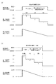
また、第1残時間表示手段52については、操作有効時間に端数がない場合(例えば3秒)には、図15(a)及び図16(a)に示すように、操作有効期間の開始から単位時間である1秒経過毎に残り時間を表す秒数の表示が「3」→「2」→「1」のように段階的に変更されるのに対し、操作有効時間に端数がある場合(例えば2.4秒)には、図15(b)及び図16(b)に示すように、操作有効期間の開始時にはその端数を切り上げて得られた秒数、例えば「3」が残り時間として表示され、その後にその端数時間(例えば0.4秒)が経過した時点で例えば「3」→「2」のように残り時間の表示が変更され、その後は単位時間である1秒経過毎に残り時間を表す秒数の表示が「2」→「1」のように段階的に変更される。 As for the first remaining time display means 52, when there is no fraction in the operation effective time (for example, 3 seconds), as shown in FIGS. 15A and 16A, from the start of the operation effective period. When the display of the number of seconds representing the remaining time is changed step by step from “3” → “2” → “1” every time one second that is the unit time, the operation effective time has a fraction In (for example, 2.4 seconds), as shown in FIGS. 15B and 16B, the number of seconds obtained by rounding up the fraction at the start of the operation effective period, for example, “3” is the remaining time. After that, when the fractional time (for example, 0.4 seconds) has elapsed, the display of the remaining time is changed, for example, from “3” to “2”, and thereafter, every 1 second that is a unit time. The display of the number of seconds representing the remaining time is changed stepwise from “2” to “1”.
即ち本実施形態では、操作有効期間が、その長さを所定単位時間で割ったときに余り時間が生じる第1操作有効期間である場合には、第1残時間表示手段52による最初の表示態様(例えば「3」)の継続時間を余り時間とし、その他の表示態様(例えば「2」,「1」)の継続時間を全て所定単位時間としている。 That is, in this embodiment, when the operation effective period is the first operation effective period in which a surplus time occurs when the length is divided by a predetermined unit time, the first display mode by the first remaining time display means 52 is displayed. The duration of (for example, “3”) is set as a surplus time, and the duration of other display modes (for example, “2”, “1”) is set as a predetermined unit time.
以上のように、第1残時間表示手段52により、操作有効期間の残り時間を端数を切り上げた秒数によって段階的に表示することにより、遊技者は操作有効期間の長短を直感的に認識することが容易となり、操作手段を操作する遊技者に焦りや混乱を生じさせ難くすることができる。 As described above, the first remaining time display means 52 displays the remaining time of the operation effective period stepwise by the rounded up seconds, so that the player intuitively recognizes the length of the operation effective period. This makes it easier to cause the player operating the operating means to be impatient or confused.
また、第2残時間表示手段53については、図15(a)〜(c)に示すように操作有効時間の長短、操作演出の種類、指定操作手段の種類、指定操作態様の種類に拘わらずレベル表示領域53aを共通とし、図16(a),(b)に示すように操作有効期間の開始時に最大値を、操作有効期間の終了時に最小値である0を示すようにレベル表示部53bの減少表示の速度を操作有効時間に応じて異ならせているため、遊技者は操作有効時間の長短に拘わらず操作有効期間がその全体に対してどの程度まで経過したかを直感的に認識することが容易となり、操作手段を操作する遊技者に混乱を生じさせ難くすることができると共に、表示用データ量を小さくできるという利点がある。
As for the second remaining time display means 53, as shown in FIGS. 15A to 15C, regardless of the length of the operation effective time, the type of operation effect, the type of designated operation means, and the type of designated operation mode. The
図9の操作有効期間報知制御処理に戻って説明を続ける。S24において操作有効期間の開始から既に操作有効時間が経過した(操作有効期間が満了した)と判定された場合には(S24:Yes)、その時点で操作有効期間表示手段47による表示を終了させる操作有効期間報知終了処理(S27)が行われる。また、S24において未だ操作有効時間が経過していない(操作有効期間は満了していない)と判定された場合であっても(S24:No)、後述する操作入力管理処理(図13)において操作成功と判定された場合(S25:Yes)には操作有効期間報知終了処理(S27)が行われ、図17に示すようにその時点で操作有効期間表示手段47による表示は終了する。
Returning to the operation effective period notification control process of FIG. If it is determined in S24 that the operation effective time has already passed from the start of the operation effective period (the operation effective period has expired) (S24: Yes), the display by the operation effective period display means 47 is terminated at that time. An operation valid period notification end process (S27) is performed. Even if it is determined in S24 that the operation effective time has not yet elapsed (the operation effective period has not expired) (S24: No), an operation is performed in the operation input management process (FIG. 13) described later. When it is determined that the operation is successful (S25: Yes), an operation effective period notification end process (S27) is performed, and the display by the operation effective
操作入力管理手段93は、操作有効期間中における第1,第2演出ボタン12,13の操作状況等を管理するもので、図13に示す操作入力管理処理を、例えば定期割り込みにより所定時間間隔(ここでは4ms間隔)で実行するようになっている。
The operation input management means 93 manages the operation statuses of the first and
この操作入力管理処理(図13)では、まず操作有効期間中であるか否かが判定され(S61)、操作有効期間中でないと判定された場合(S61:No)にはここで操作入力管理処理は終了する。操作有効期間中であると判定された場合には(S61:Yes)、指定操作態様の種類(S62)に応じた処理が行われる。 In this operation input management process (FIG. 13), it is first determined whether or not the operation is valid (S61). If it is determined that the operation is not valid (S61: No), the operation input management is performed here. The process ends. When it is determined that the operation is valid (S61: Yes), processing according to the type of designated operation mode (S62) is performed.
指定操作態様が「一回押し」の場合には、指定操作手段の検出スイッチがOFFからONに切り替わったか否かが判定され(S63)、切り替わったと判定された場合(S63:Yes)には操作成功と判定され(S64)、操作入力管理処理は終了する。このように、指定操作態様が「一回押し」の場合には、操作有効期間中に指定操作手段が1回操作された時点で操作成功となる。 When the designated operation mode is “press once”, it is determined whether or not the detection switch of the designated operation means has been switched from OFF to ON (S63). When it is determined that the switch has been switched (S63: Yes), the operation is performed. It is determined that the operation is successful (S64), and the operation input management process ends. As described above, when the designated operation mode is “press once”, the operation is successful when the designated operation means is operated once during the operation valid period.
指定操作態様が「連打」の場合には、指定操作手段の検出スイッチがOFFからONに切り替わったか否かが判定され(S65)、切り替わったと判定された場合(S65:Yes)には操作回数カウンタの値が1減算される(S66)と共に、その減算後の操作回数カウンタの値が0であることを条件に操作成功と判定され(S67:Yes→S68)、操作入力管理処理は終了する。ここで、操作回数カウンタは、操作有効期間の開始時に初期値Nがセットされるため(S37)、指定操作手段の検出スイッチがOFFからONに切り替わった回数がN回に達したときに0となる。即ち、指定操作態様が「連打」の場合には、操作有効期間中に指定操作手段がN回操作された時点で操作成功となる。
When the designated operation mode is “continuous hit”, it is determined whether or not the detection switch of the designated operation means has been switched from OFF to ON (S65), and when it is determined that the switch has been switched (S65: Yes), the
指定操作態様が「長押し」の場合には、指定操作手段の検出スイッチがONのまま維持されているか否かが判定され(S69)、ONのまま維持されていると判定された場合(S69:Yes)には操作時間タイマの値が1減算される(S70)と共に、その減算後の操作時間タイマの値が0であることを条件に操作成功と判定され(S71:Yes→S72)、操作入力管理処理は終了する。一方、S69でONのまま維持されていないと判定された場合には(S69:No)、指定操作手段の検出スイッチがONからOFFに切り替わったと判定されることを条件に(S73:Yes)、操作時間タイマに例えばS38と同じ初期値がセットされる(S74)。 When the designated operation mode is “long press”, it is determined whether or not the detection switch of the designated operation means is maintained ON (S69), and when it is determined that the detection switch is maintained ON (S69). : Yes), the value of the operation time timer is decremented by 1 (S70), and it is determined that the operation is successful on the condition that the value of the operation time timer after the subtraction is 0 (S71: Yes → S72), The operation input management process ends. On the other hand, if it is determined in S69 that the switch is not maintained ON (S69: No), it is determined that the detection switch of the designated operation means has been switched from ON to OFF (S73: Yes). For example, the same initial value as in S38 is set in the operation time timer (S74).
ここで、操作時間タイマは、操作有効期間の開始時に所定時間に対応する値(例えば所定時間Tの場合は250×T)がセットされるため(S38)、指定操作手段の検出スイッチがONの状態が所定時間継続したときに0となる。即ち、指定操作態様が「長押し」の場合には、操作有効期間中に指定操作手段が操作されたままの状態で所定時間経過した時点で操作成功となる。 Here, since the value corresponding to the predetermined time (for example, 250 × T in the case of the predetermined time T) is set to the operation time timer at the start of the operation effective period (S38), the detection switch of the designated operation means is ON. It becomes 0 when the state continues for a predetermined time. That is, when the designated operation mode is “long press”, the operation is successful when a predetermined time elapses while the designated operation unit is operated during the operation valid period.
操作時演出制御手段94は、操作有効期間中に第1,第2演出ボタン12,13が指定操作態様で操作された場合の操作時演出を制御するもので、図14に示す操作時演出制御処理を、例えば定期割り込みにより所定時間間隔(ここでは4ms間隔)で実行するようになっている。
The operation effect control means 94 controls the operation effect when the first and
この操作時演出制御処理(図14)では、まず操作入力管理手段93によって操作成功と判定されたか否かが判定され(S81)、操作成功と判定されていない場合(S81:No)にはここで操作時演出制御処理は終了する。操作成功と判定された場合には(S81:Yes)、指定操作手段の種類に応じて以下の処理が行われる。 In this operational effect control process (FIG. 14), it is first determined whether or not the operation input management means 93 has determined that the operation is successful (S81), and if it is not determined that the operation has been successful (S81: No), The operation effect control process ends. If it is determined that the operation is successful (S81: Yes), the following processing is performed according to the type of the designated operation means.
まず指定操作手段が第1演出ボタン12である場合、即ち第1通常操作演出又は第1特別操作演出の何れかである場合には、第1操作演出フラグの値が判定され(S83)、第1操作演出フラグの値が1であることを条件に、例えば回転灯16を作動させる回転灯作動演出(操作時演出)が行われ(S84)、操作時演出制御処理は終了する。このように第1通常操作演出又は第1特別操作演出では、操作有効期間中に遊技者が第1演出ボタン12を指定操作態様で操作した場合であっても、操作時演出である回転灯作動演出が行われない場合もあるが、第1通常操作演出の場合には、図5に示すように回転灯作動演出(操作時演出)が行われるのは大当たりの場合に限られるため、第1通常操作演出で回転灯作動演出が行われた場合には必ず大当たりとなる。第1特別操作演出の場合には、図6に示すように確変大当たりの場合には操作時演出ありの選択率が100%であるのに対し、時短大当たりの場合には操作時演出なしの選択率が100%となっているため、第1特別操作演出で回転灯作動演出が行われた場合には、大当たりになるとすればそれが確変大当たりであることが確定する。
First, when the designated operation means is the
なお、回転灯作動演出は、回転灯16を実際に作動させるだけでなく、回転灯が作動している状態を示す動画を画像表示手段20に表示する等、画像表示手段20による回転灯作動演出(以下、画像による回転灯作動演出という)を並行して実行するようにしてもよい。この場合、回転灯作動演出の終了時には、画像表示手段20上に表示した回転灯の画像は例えばフェードアウトにより消去することが望ましい。
The rotating lamp operation effect is not only the actual operation of the
一方、指定操作手段が第2演出ボタン13である場合、即ち第2操作演出の場合には、第2操作演出フラグの値が判定され(S85)、第2操作演出フラグの値が0であれば画像表示手段20の背景色が青に変化する青背景処理が行われ(S86)、第2操作演出フラグの値が1であれば画像表示手段20の背景色が赤に変化する赤背景処理が行われ(S87)、操作時演出制御処理は終了する。このように第2操作演出では、操作有効期間中に遊技者が第2演出ボタン13を指定操作態様で操作すれば必ず操作時演出、即ち青背景処理と赤背景処理との何れかが実行されるが、赤背景処理の方が青背景処理よりも大当たり期待度が高く、また大当たりとなった場合の確変期待度も高いため(図7参照)、遊技者の期待感は青背景処理よりも赤背景処理の方がより大きくなる。
On the other hand, when the designated operation means is the
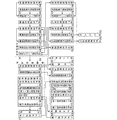
図18及び図19は本発明の第2の実施形態を例示し、第1の実施形態を一部変更して、操作有効時間を所定単位時間(例えば1秒)で割ったときに余り時間が生じる場合には、第1残時間表示手段52による第1残時間報知画像の変更回数を、余り時間を切り捨てた操作有効時間の場合と同じにした例を示している。なお、本実施形態のパチンコ機の構成で第1の実施形態と異なるのは、操作有効期間報知制御手段92による操作有効期間報知制御処理(図9)のうち、操作有効期間報知開始処理(S23;図10)における第1残時間報知設定処理(S33;図18)の一部のみである。以下、第1の実施形態との相違部分を中心に説明する。 18 and 19 exemplify the second embodiment of the present invention. When the operation effective time is divided by a predetermined unit time (for example, 1 second) by partially changing the first embodiment, the remaining time is shown. When it occurs, an example is shown in which the number of changes of the first remaining time notification image by the first remaining time display means 52 is made the same as in the case of the operation effective time with the remainder time cut off. The configuration of the pachinko machine of the present embodiment is different from that of the first embodiment in the operation effective period notification start process (S23) in the operation effective period notification control process (FIG. 9) by the operation effective period notification control unit 92. ; Only a part of the first remaining time notification setting process (S33; FIG. 18) in FIG. The following description will focus on the differences from the first embodiment.
本実施形態の第1残時間報知設定処理(図18)では、操作有効時間に端数があると判定された場合、即ち操作有効時間を所定単位時間で割ったときに余り時間が生じる場合(操作有効期間が第1操作有効期間である場合)には(S41:Yes)、その端数(余り時間)を切り捨てて得られた秒数が、第1残時間表示手段52によって表示される操作有効期間の残り時間を示す残り時間カウンタに初期値としてセットされる(S42a)。例えば操作有効時間が3.4秒であれば残り時間カウンタには「3」がセットされる。 In the first remaining time notification setting process (FIG. 18) of the present embodiment, when it is determined that there is a fraction in the operation effective time, that is, when a surplus time occurs when the operation effective time is divided by a predetermined unit time (operation When the effective period is the first operation effective period (S41: Yes), the operation effective period in which the first remaining time display means 52 displays the number of seconds obtained by rounding down the fraction (remaining time). The remaining time counter indicating the remaining time is set as an initial value (S42a). For example, if the operation valid time is 3.4 seconds, “3” is set in the remaining time counter.
また、操作有効時間の端数(余り時間)に単位時間である1秒を加算して得られた時間(特定時間)に対応する値が初期値として表示更新タイマにセットされる(S43a)。例えば、操作有効時間の端数が0.4秒であれば表示更新タイマには初期値として1.4秒に対応する「350」がセットされる。そして、残り時間カウンタの値に対応する第1残時間報知画像が設定され(S44)、第1残時間報知設定処理は終了する。 Further, a value corresponding to a time (specific time) obtained by adding 1 second as a unit time to a fraction (remainder time) of the operation effective time is set in the display update timer as an initial value (S43a). For example, if the fraction of the operation valid time is 0.4 seconds, “350” corresponding to 1.4 seconds is set as the initial value in the display update timer. Then, the first remaining time notification image corresponding to the value of the remaining time counter is set (S44), and the first remaining time notification setting process ends.
一方、操作有効時間(秒)に端数がないと判定された場合には(S41:No)、第1の実施形態と同様、その操作有効時間の秒数がそのまま残り時間カウンタに初期値としてセットされ(S45)、また単位時間である1秒に対応する値が初期値として表示更新タイマにセットされる(S46)。例えば操作有効時間が3秒であれば、残り時間カウンタには「3」が、表示更新タイマには「250」がセットされる。そして、残り時間カウンタの値に対応する第1残時間報知画像が設定され(S44)、第1残時間報知設定処理は終了する。 On the other hand, if it is determined that the operation effective time (seconds) is not a fraction (S41: No), the operation effective time seconds are set as initial values in the remaining time counter as in the first embodiment. Then, a value corresponding to 1 second, which is a unit time, is set as an initial value in the display update timer (S46). For example, if the operation valid time is 3 seconds, “3” is set in the remaining time counter and “250” is set in the display update timer. Then, the first remaining time notification image corresponding to the value of the remaining time counter is set (S44), and the first remaining time notification setting process ends.
続いて、図12に示す操作有効期間報知中処理について説明する。なお、この操作有効期間報知中処理(図12)の処理手順は第1の実施形態と全く同じであるが、上述したように操作有効時間に端数がある場合の残り時間カウンタ及び表示更新タイマの初期値が第1の実施形態とは異なるため、この操作有効期間報知中処理(図12)による第1残時間表示手段52の表示内容も第1の実施形態の場合とは一部異なっている。即ち、操作誘導表示手段51についてそのまま表示を継続する処理が行われた後(S51)、表示更新タイマの値が1減算され(S52)、その減算後の表示更新タイマの値が0であるか否かが判定される(S53)。 Next, the operation valid period notification process shown in FIG. 12 will be described. Note that the processing procedure of the operation valid period notification process (FIG. 12) is exactly the same as in the first embodiment, but as described above, the remaining time counter and display update timer when the operation valid time has a fraction are displayed. Since the initial value is different from that of the first embodiment, the display content of the first remaining time display means 52 by the operation effective period notification processing (FIG. 12) is also partially different from that of the first embodiment. . That is, after the operation guidance display means 51 is subjected to the process of continuing display (S51), the display update timer value is decremented by 1 (S52), and the display update timer value after the subtraction is 0? It is determined whether or not (S53).
この表示更新タイマには、操作有効期間の開始時に、その操作有効時間に端数がある場合にはその端数+1秒(単位時間)に対応する値が、端数がない場合には単位時間である1秒に対応する値が初期値としてセットされている(図18のS43a,S46)。従って、操作有効時間に端数がある場合(例えば3.4秒)には操作有効期間の開始からその端数時間+1秒(例えば1.4秒)が経過した時点で表示更新タイマの値は0になり、また操作有効時間に端数がない場合(例えば3秒)には操作有効期間の開始から単位時間である1秒が経過した時点で表示更新タイマの値は0になる。 The display update timer has a value corresponding to the fraction plus one second (unit time) when the operation effective time has a fraction at the start of the operation effective period, and is a unit time when there is no fraction. A value corresponding to the second is set as an initial value (S43a and S46 in FIG. 18). Therefore, when the operation effective time has a fraction (for example, 3.4 seconds), the value of the display update timer is set to 0 when the fraction time + 1 second (for example, 1.4 seconds) has elapsed from the start of the operation effective period. When the operation effective time has no fraction (for example, 3 seconds), the value of the display update timer becomes 0 when 1 second as the unit time has elapsed from the start of the operation effective period.
そして、表示更新タイマの値が0であると判定された場合には(S53:Yes)、新たに単位時間である1秒に対応する値が表示更新タイマにセットされると共に(S54)、残り時間カウンタの値が1減算される(S55)。 If it is determined that the value of the display update timer is 0 (S53: Yes), a value corresponding to 1 second, which is a unit time, is newly set in the display update timer (S54), and the rest The value of the time counter is decremented by 1 (S55).
この残り時間カウンタには、操作有効期間の開始時に、その操作有効時間に端数がある場合にはその端数を切り捨てて得られた秒数が、端数がない場合にはその操作有効時間の秒数が初期値としてセットされている(図18のS42a,S45)。従って、操作有効時間が例えば3.4秒の場合と3秒の場合とは共に、操作有効期間の開始後に表示更新タイマが最初に0となった時点で残り時間カウンタの値が3から2に変化する。 In this remaining time counter, when the operation effective period starts, if there is a fraction in the operation effective time, the number of seconds obtained by rounding down the fraction is displayed. If there is no fraction, the operation effective time in seconds Is set as an initial value (S42a and S45 in FIG. 18). Accordingly, in both cases where the operation effective time is, for example, 3.4 seconds and 3 seconds, the value of the remaining time counter is changed from 3 to 2 when the display update timer first becomes 0 after the operation effective period starts. Change.
そして、その減算後の残り時間カウンタの値が0であれば(S56:Yes)、操作有効時間が既に経過したものと判断できるため、例えばそのまま操作有効期間報知中処理は終了するが、減算後の残り時間カウンタの値が0でなければ(S56:No)、第1残時間表示手段52による画像がその減算後の残り時間カウンタの値に対応する画像に更新され(S57)、第2残時間表示手段53については上述したように報知開始時(S34)に算出された減少速度に基づいてレベル表示部53bの表示が更新され(S58)、操作有効期間報知中処理は終了する。
If the value of the remaining time counter after the subtraction is 0 (S56: Yes), it can be determined that the operation effective time has already passed. If the value of the remaining time counter is not 0 (S56: No), the image by the first remaining time display means 52 is updated to an image corresponding to the value of the remaining time counter after the subtraction (S57). Regarding the time display means 53, as described above, the display of the
以上の操作有効期間報知中処理が、操作有効期間中に繰り返し実行されることにより、第1残時間表示手段52については、操作有効時間に端数がない場合(例えば3秒)には、図15(a)及び図16(a)に示すように、操作有効期間の開始から単位時間である1秒経過毎に残り時間を表す秒数の表示が「3」→「2」→「1」のように段階的に変更されるのに対し、操作有効時間に端数がある場合(例えば3.4秒)には、図15(b)及び図19に示すように、操作有効期間の開始時にはその端数を切り捨てて得られた秒数、例えば「3」が残り時間として表示され、その後にその端数時間+1秒(例えば1.4秒)が経過した時点で例えば「3」→「2」のように残り時間の表示が変更され、その後は単位時間である1秒経過毎に残り時間を表す秒数の表示が「2」→「1」のように段階的に変更される。 When the above-described operation valid period notification process is repeatedly executed during the operation valid period, the first remaining time display means 52 has a fraction in the operation valid time (for example, 3 seconds). As shown in (a) and FIG. 16 (a), the display of the number of seconds representing the remaining time for every one second that is a unit time from the start of the operation effective period is “3” → “2” → “1”. However, when the operation effective time has a fraction (eg, 3.4 seconds), as shown in FIG. 15B and FIG. 19, at the start of the operation effective period, The number of seconds obtained by rounding down the fraction, for example “3”, is displayed as the remaining time, and after that fraction time + 1 second (for example, 1.4 seconds) has elapsed, for example, “3” → “2”. The display of the remaining time is changed to every 1 second, which is the unit time thereafter. Ri display of the number of seconds representing the time is "2" → be changed in stages such as "1".
即ち本実施形態では、操作有効期間が、その長さを所定単位時間で割ったときに余り時間が生じる第1操作有効期間である場合には、第1残時間表示手段52による最初の表示態様(例えば「3」)の継続時間を余り時間+所定単位時間(特定時間)とし、その他の表示態様(例えば「2」,「1」)の継続時間を全て所定単位時間としている。 That is, in this embodiment, when the operation effective period is the first operation effective period in which a surplus time occurs when the length is divided by a predetermined unit time, the first display mode by the first remaining time display means 52 is displayed. The duration of (for example, “3”) is set as the extra time + predetermined unit time (specific time), and the duration of other display modes (for example, “2”, “1”) is set as the predetermined unit time.
以上のように、第1残時間表示手段52により、操作有効期間の残り時間を端数を切り捨てた秒数によって段階的に表示する本実施形態の場合も、操作有効期間の残り時間を端数を切り上げた秒数によって段階的に表示する第1の実施形態の場合と同様、遊技者は操作有効期間の長短を直感的に認識することが容易となり、操作手段を操作する遊技者に焦りや混乱を生じさせ難くすることができる。 As described above, even in the case of the present embodiment in which the remaining time of the operation effective period is displayed stepwise by the number of seconds rounded down by the first remaining time display means 52, the remaining time of the operation effective period is rounded up. As in the case of the first embodiment, which displays in stages according to the number of seconds, it becomes easy for the player to intuitively recognize the length of the operation effective period, and the player who operates the operation means is irritated and confused. It can be made difficult to generate.
図20は本発明の第3の実施形態を例示し、第1残時間表示手段52により、所定画像の個数を増減可能に構成し、操作有効期間の残り時間を数字ではなくその所定画像の表示個数で表すようにした例を示している。 FIG. 20 illustrates the third embodiment of the present invention, wherein the first remaining time display means 52 is configured so that the number of predetermined images can be increased and decreased, and the remaining time of the operation valid period is displayed instead of numbers. An example in which the number is expressed is shown.
図20に示すように、本実施形態の第1残時間表示手段52は、長方形のブロック画像の表示個数により操作有効期間の残り時間を報知するようになっている。このように、第1残時間表示手段52は、表示態様を段階的に変更することにより操作有効期間の経過状況(ここでは残り時間)を報知するものであればよく、その表示態様の種類は任意である。 As shown in FIG. 20, the first remaining time display means 52 of the present embodiment notifies the remaining time of the operation effective period based on the number of displayed rectangular block images. Thus, the 1st remaining time display means 52 should just alert | report the progress condition (here remaining time) of an operation effective period by changing a display mode in steps, The kind of the display mode is Is optional.
図21は本発明の第4の実施形態を例示し、第2残時間表示手段53による表示内容の変更例を示したものである。図21(a)は、レベル表示領域53aを横長状とし、そのレベル表示領域53aの一端側(左端側)から他端側(右端側)に向けて帯状のレベル表示部53bを表示するように構成した例を示している。また、図21(b)は、レベル表示領域53aを円形とし、そのレベル表示領域53a内に、扇形のレベル表示部53bを表示するように構成した例を示している。このように、第2残時間表示手段53によるレベル表示領域53aの形状、大きさ、長さ等は任意であり、またレベル表示部53bの形状、変化方向等についてもレベル表示領域53aの形状等に応じて任意に設定可能である。
FIG. 21 illustrates a fourth embodiment of the present invention, and shows an example of changing display contents by the second remaining time display means 53. In FIG. 21A, the
図22は本発明の第5の実施形態を例示し、第1の実施形態を一部変更して、操作有効期間が、その長さを所定単位時間で割ったときに余り時間が生じる第1操作有効期間である場合に、最初の表示態様(ここでは「3」)ではなく最後の表示態様(ここでは「1」)の継続期間を余り時間とした例を示している。このように、表示継続時間を余り時間とするのは最初の表示態様に限られるものではない。 FIG. 22 illustrates the fifth embodiment of the present invention. The first embodiment is partially changed, and the operation effective period is a first time in which a surplus time occurs when the length is divided by a predetermined unit time. In the operation effective period, an example is shown in which the continuation period of the last display mode (here, “1”) is not the first display mode (here, “3”) but the remaining time. In this way, the display duration time is not limited to the first display mode.
図23は本発明の第6の実施形態を例示し、第2の実施形態を一部変更して、操作有効期間が、その長さを所定単位時間で割ったときに余り時間が生じる第1操作有効期間である場合に、最初の表示態様(ここでは「3」)ではなく最後の表示態様(ここでは「1」)の継続期間を、余り時間に所定単位時間(ここでは1秒)を加算した特定時間とした例を示している。このように、表示継続時間を余り時間に所定単位時間を加算した特定時間とするのは最初の表示態様に限られるものではない。 FIG. 23 illustrates the sixth embodiment of the present invention. The second embodiment is partially modified, and the operation effective period is a first time in which a surplus time occurs when the length is divided by a predetermined unit time. When the operation is valid, the duration of the last display mode (here, “1”) is used instead of the first display mode (here, “3”), and a predetermined unit time (here, 1 second) is used as the remaining time. An example of the added specific time is shown. As described above, the display duration is not limited to the first display mode as the specific time obtained by adding the predetermined unit time to the extra time.
以上、本発明の実施形態について詳述したが、本発明はこれらの実施形態に限定されるものではなく、本発明の趣旨を逸脱しない範囲で種々の変更が可能である。例えば、所定単位時間は1秒に限られるものではなく、1.5秒、2秒等であってもよい。例えば所定単位時間を1.5秒とした場合、操作有効時間が3秒であれば余り時間は生じないが、操作有効時間が4秒であれば余り時間は1秒となる。 As mentioned above, although embodiment of this invention was explained in full detail, this invention is not limited to these embodiment, A various change is possible in the range which does not deviate from the meaning of this invention. For example, the predetermined unit time is not limited to 1 second, and may be 1.5 seconds, 2 seconds, or the like. For example, if the predetermined unit time is 1.5 seconds, the surplus time does not occur if the operation effective time is 3 seconds, but if the operation effective time is 4 seconds, the surplus time is 1 second.
実施形態では演出用の操作手段を2つ設けた例を示したが、3つ以上設けてもよい。また、操作手段の種類は任意であり、押しボタン式に限らず、1又は複数方向に操作可能なレバー式、タッチパネル式等でもよい。また、少なくとも一つを他と異なる種類の操作手段としてもよい。 In the embodiment, an example in which two operation means for production are provided is shown, but three or more may be provided. The type of operation means is arbitrary, and is not limited to a push button type, and may be a lever type or a touch panel type that can be operated in one or a plurality of directions. Also, at least one may be a different type of operation means.
指定操作態様の選択肢は操作手段毎に1つのみであってもよいし、実施形態のように複数設けてもよい。また、指定操作態様は操作手段の種類に応じて適宜設定可能である。例えば、複数方向に操作可能なレバー式の操作手段の場合には、所定順序に従った連続操作を指定操作態様の選択肢に含めてもよい。 Only one option for the designated operation mode may be provided for each operation means, or a plurality of options may be provided as in the embodiment. The designated operation mode can be set as appropriate according to the type of operation means. For example, in the case of a lever-type operation means that can be operated in a plurality of directions, a continuous operation according to a predetermined order may be included in the options of the designated operation mode.
操作有効期間表示手段47による画像表示手段20上における表示位置は任意であり、操作演出の種類、指定操作手段の種類、指定操作態様の種類、操作演出による報知対象等に応じて適宜変更するようにしてもよい。例えば、第2操作演出によって保留記憶の先読み予告を行う場合には、特別保留個数表示手段46付近で操作有効期間表示手段47による表示を行うようにしてもよく、また第2操作演出が例えば操作成功時に所定のメッセージを表示させるものである場合には、当該メッセージの表示位置付近で操作有効期間表示手段47による表示を行うようにしてもよい。
The display position on the image display means 20 by the operation valid period display means 47 is arbitrary, and is appropriately changed according to the type of operation effect, the type of designated operation means, the type of designated operation mode, the notification target by the operation effect, and the like. It may be. For example, when the pre-reading advance notice of the hold storage is performed by the second operation effect, the operation effective
また、遊技者の注目度の高さに応じて操作有効期間表示手段47による表示位置を変化させてもよい。例えば、実施形態における第1特別操作演出のように操作成功時に当該図柄変動の結果を予告する操作演出を実行する場合には、操作有効期間表示手段47による表示位置を、最も視認性の高い画像表示手段20の略中央とすることが望ましい。また、複数の操作演出(第1通常操作演出、第1特別操作演出、第2操作演出等)で同内容の予告(当該図柄変動結果の予告等)を行う場合には、期待度の高さに応じて、より期待度の高い操作演出(例えば第1通常操作演出及び第1特別操作演出)についてのみ、操作有効期間表示手段47による表示位置を画像表示手段20の略中央としてもよい。このように操作演出に応じて大当たり等の期待度を異ならせることで操作演出が単調になるのを防ぎ、演出面の向上を図ることができる。 Further, the display position by the operation valid period display means 47 may be changed according to the level of attention of the player. For example, in the case where an operation effect for notifying the result of the symbol variation is executed when the operation is successful, such as the first special operation effect in the embodiment, the display position by the operation effective period display means 47 is the image with the highest visibility. It is desirable that the display means 20 be approximately at the center. Also, when a plurality of operation effects (a first normal operation effect, a first special operation effect, a second operation effect, etc.) are given with the same content (such as a notice of the symbol variation result), the degree of expectation is high. Accordingly, the display position by the operation valid period display means 47 may be set to the approximate center of the image display means 20 only for operation effects with higher expectations (for example, the first normal operation effect and the first special operation effect). Thus, by changing the degree of expectation such as jackpot according to the operation effect, it is possible to prevent the operation effect from becoming monotonous and to improve the effect surface.
操作有効期間表示手段47による表示開始時及び表示終了時には、フェードイン、フェードアウト等の処理を適宜用いることが望ましい。図24は図10におけるS36の操作有効期間表示開始処理の一例であり、図25は図9におけるS27の操作有効期間報知終了処理の一例である。それぞれについて簡単に説明する。 It is desirable to appropriately use processing such as fade-in and fade-out at the start and end of display by the operation valid period display means 47. 24 is an example of the operation valid period display start process of S36 in FIG. 10, and FIG. 25 is an example of the operation valid period notification end process of S27 in FIG. Each will be briefly described.
図24に示す操作有効期間表示開始処理では、例えば指定操作手段表示手段51a及び第2残時間表示手段53による画像がフェードインにより表示され(S101)、更に指定操作態様表示手段51b及び第1残時間表示手段52による画像が表示される(S102,S103)。そして、例えば指定操作手段が操作される状態を示すアニメーションが開始され(S104)、操作有効期間表示開始処理は終了する。なお、フェードインにより表示する画像はこのように操作有効期間表示手段47による一部の画像のみであってもよいし、操作有効期間表示手段47による画像全体であってもよい。
In the operation effective period display start process shown in FIG. 24, for example, the images by the designated operation means display means 51a and the second remaining time display means 53 are displayed by fade-in (S101), and the designated operation mode display means 51b and the first remaining time display are displayed. An image by the time display means 52 is displayed (S102, S103). Then, for example, an animation indicating a state in which the designated operation means is operated is started (S104), and the operation valid period display start process is ended. Note that the image displayed by the fade-in may be only a part of the image by the operation effective
図25に示す操作有効期間報知終了処理では、操作有効期間終了の理由が操作有効時間の経過であるか否かが判定される(S111)。そして、操作有効期間終了の理由が操作有効時間の経過ではなく、操作成功によるものである場合には(S111:No)、原則として操作有効期間表示手段47による画像全体がフェードアウトにより画面上から消去され(S116)、操作有効期間報知終了処理は終了するが、例えば画像による回転灯作動演出が実行される場合には(S112:Yes)、操作有効期間表示手段47による画像のうち、指定操作手段表示手段51aによる第1演出ボタン12の画像のみを残し、その他の画像、即ち指定操作態様表示手段51b、第1残時間表示手段52、第2残時間表示手段53による各画像が画面上から消去され(S113〜S115)、操作有効期間報知終了処理は終了する。これにより、操作成功時には指定操作手段表示手段51aによる第1演出ボタン12の画像をそのまま用いて画像による回転灯作動演出を行うことができると共に、遊技者が操作有効期間表示手段47による操作有効期間の表示と誤認することを防止できる。なお、回転灯作動演出の終了時には、画像表示手段20上に表示した第1演出ボタン12の画像は例えばフェードアウトにより消去することが望ましい。
In the operation effective period notification end process shown in FIG. 25, it is determined whether or not the reason for the operation effective period end is the elapse of the operation effective time (S111). If the reason for the end of the operation effective period is not the operation effective time but the success of the operation (S111: No), the entire image by the operation effective period display means 47 is erased from the screen by the fade-out in principle. In step S116, the operation valid period notification end process ends. For example, when a rotating lamp operation effect is executed by an image (S112: Yes), the designated operation means is included in the image by the operation valid period display means 47. Only the image of the
一方、操作有効期間終了の理由が操作有効時間の経過である場合、即ち操作有効期間中に操作成功と判定されなかった場合には(S111:Yes)、操作有効期間表示手段47による画像全体がフェードアウトにより画面上から消去される(S117)と共に、操作有効期間終了画像、例えば画面全体を覆う煙幕の画像等が表示され(S118)、操作有効期間報知終了処理は終了する。 On the other hand, when the reason for the end of the operation effective period is the elapse of the operation effective time, that is, when it is not determined that the operation is successful during the operation effective period (S111: Yes), the entire image by the operation effective period display means 47 is displayed. The screen is erased from the screen by fading out (S117), and an operation valid period end image, for example, a smoke screen image covering the entire screen is displayed (S118), and the operation valid period notification end process is terminated.
なお、操作演出が「リーチ最後の操作演出」であって、操作有効期間中に操作成功したにも拘わらず操作時演出が実行されない場合には、例えば操作有効期間が満了するまで画像表示手段20の背景をブラックアウトさせることが望ましい。ここで、「リーチ最後の操作演出」とはリーチ演出の最終段階に実行される操作演出で、その操作演出の結果によって図柄変動の結果を報知することとなる操作演出である。リーチ演出の終了後の背景は通常画面となるが、「リーチ最後の操作演出」の操作有効期間中に操作成功したにも拘わらず操作時演出が実行されない場合、まだ操作有効期間が残っているにも拘わらずその時点で背景を通常画面に戻すと、遊技者は早々に外れを認識することとなり、本来の操作有効期間が経過するまでの残り時間が演出上意味のない時間となってしまう。そこで、「リーチ最後の操作演出」であって、操作有効期間中に操作成功したにも拘わらず操作時演出が実行されない場合には、例えば操作有効期間が満了するまで画像表示手段20の背景をブラックアウトさせることで、遊技者の期待感を維持することができ、本来の操作有効期間が経過するまでの残り時間を演出上有効に利用することができる。 When the operation effect is “Leach last operation effect” and the operation effect is not executed even though the operation is successful during the operation effective period, for example, the image display means 20 is displayed until the operation effective period expires. It is desirable to black out the background. Here, the “reach last operation effect” is an operation effect that is executed at the final stage of the reach effect, and is an operation effect that informs the result of the symbol variation according to the result of the operation effect. The background after reaching the reach effect will be the normal screen, but if the operation effect is not executed despite the successful operation during the “Leach last operation effect” operation effective period, the operation effective period still remains Nevertheless, if the background is returned to the normal screen at that time, the player will quickly recognize that the background is off, and the remaining time until the original operation valid period will be a meaningless time for production. . Therefore, when the “reaching last operation effect” is made and the operation effect is not executed even though the operation is successful during the operation effective period, for example, the background of the image display means 20 is displayed until the operation effective period expires. By blacking out, the player's expectation can be maintained, and the remaining time until the original operation effective period elapses can be used effectively for production.
各操作演出における操作有効時間は任意に設定可能である。図26は、操作演出の種類(指定操作手段の種類)毎、指定操作態様の種類毎、図柄変動の種類毎の操作有効時間の設定例を示している。図26(a)は、リーチ変動以外の通常変動中における操作有効時間の設定例であり、全ての指定操作態様において、第1操作演出における操作有効時間が第2操作演出における操作有効時間と同じかそれよりも長くなっている。また、一部の指定操作態様(連打及び長押し)においては第1操作演出と第2操作演出とで操作有効時間が同じに設定されている。更に、一回押しよりも連打、長押しの場合の方が操作有効時間が長くなっている。これらの傾向は、図26(b)に示すリーチ変動中(リーチ最後の操作演出の場合を除く)における操作有効時間の設定例においても同様である。なお、一部の指定操作態様においては第2操作演出における操作有効時間が第1操作演出における操作有効時間よりも長くてもよい。また、連打と長押しとで操作有効時間が異なっていてもよい。 The operation effective time in each operation effect can be arbitrarily set. FIG. 26 shows an example of setting the operation effective time for each type of operation effect (type of designated operation means), for each type of designated operation mode, and for each type of symbol variation. FIG. 26A is an example of setting the operation effective time during normal fluctuations other than reach fluctuations. In all the designated operation modes, the operation effective time in the first operation effect is the same as the operation effective time in the second operation effect. Or longer. Further, in some designated operation modes (continuous hitting and long press), the operation effective time is set to be the same for the first operation effect and the second operation effect. Further, the effective operation time is longer in the case of continuous hit and long press than in the case of single press. These tendencies are the same in the setting example of the operation valid time during the reach fluctuation (except for the case of the last operation effect) shown in FIG. In some specified operation modes, the operation effective time in the second operation effect may be longer than the operation effective time in the first operation effect. Further, the effective operation time may be different between continuous hit and long press.
また、図26(a)と図26(b)とを比較すると、通常変動中の操作有効時間よりもリーチ変動中の操作有効期間の方が長くなっている。なお、少なくとも一部の指定操作態様において通常変動中とリーチ変動中とで操作有効時間が同じであってもよい。また、図26(c)はリーチ最後の操作演出における操作有効時間の設定例であり、全ての指定操作態様、全ての操作演出において操作有効時間が同じとなっている。また、図26(c)に示すリーチ最後の操作演出における操作有効時間は、図26(a)に示す通常変動中における操作有効時間、図26(b)に示すリーチ変動中(リーチ最後の操作演出の場合を除く)における操作有効時間の何れよりも長くなっている。 Further, comparing FIG. 26 (a) and FIG. 26 (b), the operation effective period during reach fluctuation is longer than the operation effective time during normal fluctuation. Note that the operation effective time may be the same during normal fluctuation and during reach fluctuation in at least some designated operation modes. FIG. 26C shows an example of setting the operation effective time in the last reach operation effect, and the operation effective time is the same in all designated operation modes and all operation effects. In addition, the operation effective time in the reach last operation effect shown in FIG. 26C is the operation effective time during the normal fluctuation shown in FIG. 26A and during the reach fluctuation shown in FIG. It is longer than any of the operation effective times in the case of production).
指定操作手段表示手段51a、指定操作態様表示手段51b、第1残時間表示手段52、第2残時間表示手段53の少なくとも一つを、画像表示手段20以外の表示手段により構成してもよい。例えば、第1残時間表示手段52は、7セグメント式等の表示手段により構成して操作有効期間の残り時間等をデジタル表示するようにしてもよいし、複数個の発光部を有する発光式表示手段により構成して操作有効期間の残り時間等を発光部の発光個数で表示するようにしてもよい。また、第2残時間表示手段53を、第1演出ボタン12等の操作手段の外周に沿って配置した円環状の発光表示手段(レベル表示領域53a)により構成して、その発光表示手段における発光部(レベル表示部53b)の長さによって操作有効期間の残り時間等を表示するようにしてもよい。
At least one of the designated operation means display means 51a, the designated operation mode display means 51b, the first remaining time display means 52, and the second remaining time display means 53 may be constituted by a display means other than the image display means 20. For example, the first remaining time display means 52 may be configured by a display means such as a 7-segment type so as to digitally display the remaining time of the operation effective period, or a light emitting display having a plurality of light emitting units. The remaining time of the operation effective period may be displayed by the number of light emission units. Further, the second remaining time display means 53 is constituted by an annular light emission display means (
第1残時間表示手段(経過状況表示手段)52は、操作有効期間の残り時間ではなく経過時間を表示するようにしてもよい。また、第1残時間表示手段52は、操作有効期間中常に表示する必要はなく、例えば操作有効期間の残り時間が所定時間よりも短くなったタイミングで表示開始するようにしてもよい。その場合の所定時間は一定(例えば常に3秒)であってもよいし、操作有効時間の長短等に応じて変化させてもよい。 The first remaining time display means (elapsed state display means) 52 may display the elapsed time instead of the remaining time of the operation effective period. The first remaining time display means 52 need not always display during the operation effective period. For example, the first remaining time display means 52 may start the display when the remaining time of the operation effective period becomes shorter than a predetermined time. The predetermined time in that case may be constant (for example, always 3 seconds), or may be changed according to the length of the operation effective time.
また、第2残時間表示手段(レベル表示手段)53は、操作有効期間の経過時間の増加に応じてレベル表示領域53aに占めるレベル表示部53bの割合を増加させるように構成し、そのレベル表示領域53aの増加表示の速度を操作有効期間の長さに応じて異ならせてもよい。
The second remaining time display means (level display means) 53 is configured to increase the proportion of the
必ずしも第1残時間表示手段(経過状況表示手段)52と第2残時間表示手段(レベル表示手段)53との両方を設ける必要はなく、例えば第1残時間表示手段52を省略してもよい。 It is not always necessary to provide both the first remaining time display means (elapsed status display means) 52 and the second remaining time display means (level display means) 53. For example, the first remaining time display means 52 may be omitted. .
第1特別操作演出実行時は、操作成功の場合の操作時演出(回転灯作動演出等)の実行中も指定操作手段表示手段51aの表示を継続して行うようにしてもよい。 When the first special operation effect is executed, the designation operation means display means 51a may be continuously displayed even while the operation time effect (such as a rotating lamp operation effect) in the case of successful operation is being executed.
例えば特別利益状態の最初のラウンド中に十字キー等の操作手段の操作を有効として演出内容(例えばBGM)を選択可能とする場合のように、操作有効時間が変動する場合には第1残時間表示手段52、第2残時間表示手段53による表示は行わないようにしてもよい。 For example, when the operation effective time fluctuates, such as when the operation content such as the cross key is enabled during the first round of the special profit state and the production content (for example, BGM) can be selected, the first remaining time The display by the display means 52 and the second remaining time display means 53 may not be performed.
また本発明は、アレンジボール機、雀球遊技機等の各種弾球遊技機の他、スロットマシン等の弾球遊技機以外の遊技機においても同様に実施することが可能である。 Further, the present invention can be similarly implemented in game machines other than ball game machines such as slot machines, in addition to various ball game machines such as arrange ball machines and sparrow ball game machines.
12 第1演出ボタン(操作手段)
13 第2演出ボタン(操作手段)
51 操作誘導表示手段
53 第2残時間表示手段(レベル表示手段)
53a レベル表示領域
53b レベル表示部
85 操作演出制御手段(演出制御手段)
92a〜92d 第1〜第4記憶手段(記憶手段)
12 First effect button (operation means)
13 Second effect button (operation means)
51 Operation guidance display means 53 Second remaining time display means (level display means)
53a
92a to 92d First to fourth storage means (storage means)
Claims (4)
操作有効期間中に前記操作手段が操作された場合に所定の演出を実行させる演出制御手段と、
前記操作有効期間の残り時間又は経過時間の減少又は増加に応じて、レベル表示領域に占めるレベル表示部の割合を減少又は増加させるレベル表示手段と
を備えた遊技機において、
前記操作手段を複数備え、
前記演出制御手段の制御により前記複数の操作手段にそれぞれ対応する複数種類の前記演出を実行可能であり、
前記レベル表示手段による前記レベル表示領域は前記各演出に対応する前記操作有効期間の長さ及び前記操作手段に拘わらず共通とし、
前記レベル表示部の減少又は増加の速度を前記操作有効期間の長さに応じて異ならせた
ことを特徴とする遊技機。 Operation means operable from the outside;
Effect control means for executing a predetermined effect when the operation means is operated during the operation valid period;
In a gaming machine comprising level display means for reducing or increasing a ratio of a level display portion in a level display area in accordance with a decrease or increase in the remaining time or elapsed time of the operation effective period,
A plurality of the operating means;
A plurality of types of effects corresponding to the plurality of operation means can be executed under the control of the effect control means,
The level display area by the level display means is common regardless of the length of the operation effective period corresponding to each effect and the operation means,
The gaming machine, wherein the speed of decrease or increase of the level display unit is varied according to the length of the operation effective period.
ことを特徴とする請求項1に記載の遊技機。 The ratio of the level display section in the level display area is configured to be maximum or minimum at the start of the operation effective period and minimum or maximum at the end of the operation effective period. The gaming machine described in 1.
ことを特徴とする請求項1又は2に記載の遊技機。 The gaming machine according to claim 1 or 2, further comprising operation guidance display means for performing operation guidance display for prompting the operation of the operation means during the operation valid period.
前記操作誘導表示手段と前記レベル表示手段とがそれぞれ前記記憶手段から前記表示用データを読み出して表示するように構成した
ことを特徴とする請求項3に記載の遊技機。 Storage means for individually storing the display data for the operation guidance display means and the display data for the level display means;
The gaming machine according to claim 3, wherein the operation guidance display means and the level display means are configured to read and display the display data from the storage means, respectively.
Priority Applications (1)
| Application Number | Priority Date | Filing Date | Title |
|---|---|---|---|
| JP2013151857A JP2015019951A (en) | 2013-07-22 | 2013-07-22 | Game machine |
Applications Claiming Priority (1)
| Application Number | Priority Date | Filing Date | Title |
|---|---|---|---|
| JP2013151857A JP2015019951A (en) | 2013-07-22 | 2013-07-22 | Game machine |
Publications (2)
| Publication Number | Publication Date |
|---|---|
| JP2015019951A true JP2015019951A (en) | 2015-02-02 |
| JP2015019951A5 JP2015019951A5 (en) | 2016-09-01 |
Family
ID=52484946
Family Applications (1)
| Application Number | Title | Priority Date | Filing Date |
|---|---|---|---|
| JP2013151857A Pending JP2015019951A (en) | 2013-07-22 | 2013-07-22 | Game machine |
Country Status (1)
| Country | Link |
|---|---|
| JP (1) | JP2015019951A (en) |
Cited By (7)
| Publication number | Priority date | Publication date | Assignee | Title |
|---|---|---|---|---|
| JP2020022705A (en) * | 2018-08-09 | 2020-02-13 | 株式会社大一商会 | Game machine |
| JP2020022707A (en) * | 2018-08-09 | 2020-02-13 | 株式会社大一商会 | Game machine |
| JP2020022710A (en) * | 2018-08-09 | 2020-02-13 | 株式会社大一商会 | Game machine |
| JP2020022704A (en) * | 2018-08-09 | 2020-02-13 | 株式会社大一商会 | Game machine |
| JP2020022706A (en) * | 2018-08-09 | 2020-02-13 | 株式会社大一商会 | Game machine |
| JP2020022709A (en) * | 2018-08-09 | 2020-02-13 | 株式会社大一商会 | Game machine |
| JP2020022708A (en) * | 2018-08-09 | 2020-02-13 | 株式会社大一商会 | Game machine |
Citations (3)
| Publication number | Priority date | Publication date | Assignee | Title |
|---|---|---|---|---|
| JP2011177421A (en) * | 2010-03-03 | 2011-09-15 | Fujishoji Co Ltd | Game machine |
| JP2012223521A (en) * | 2011-04-22 | 2012-11-15 | Sankyo Co Ltd | Game machine |
| JP2013111240A (en) * | 2011-11-29 | 2013-06-10 | Maruhon Industry Co Ltd | Pachinko machine |
-
2013
- 2013-07-22 JP JP2013151857A patent/JP2015019951A/en active Pending
Patent Citations (3)
| Publication number | Priority date | Publication date | Assignee | Title |
|---|---|---|---|---|
| JP2011177421A (en) * | 2010-03-03 | 2011-09-15 | Fujishoji Co Ltd | Game machine |
| JP2012223521A (en) * | 2011-04-22 | 2012-11-15 | Sankyo Co Ltd | Game machine |
| JP2013111240A (en) * | 2011-11-29 | 2013-06-10 | Maruhon Industry Co Ltd | Pachinko machine |
Cited By (7)
| Publication number | Priority date | Publication date | Assignee | Title |
|---|---|---|---|---|
| JP2020022705A (en) * | 2018-08-09 | 2020-02-13 | 株式会社大一商会 | Game machine |
| JP2020022707A (en) * | 2018-08-09 | 2020-02-13 | 株式会社大一商会 | Game machine |
| JP2020022710A (en) * | 2018-08-09 | 2020-02-13 | 株式会社大一商会 | Game machine |
| JP2020022704A (en) * | 2018-08-09 | 2020-02-13 | 株式会社大一商会 | Game machine |
| JP2020022706A (en) * | 2018-08-09 | 2020-02-13 | 株式会社大一商会 | Game machine |
| JP2020022709A (en) * | 2018-08-09 | 2020-02-13 | 株式会社大一商会 | Game machine |
| JP2020022708A (en) * | 2018-08-09 | 2020-02-13 | 株式会社大一商会 | Game machine |
Similar Documents
| Publication | Publication Date | Title |
|---|---|---|
| JP5784079B2 (en) | Game machine | |
| JP6007154B2 (en) | Game machine | |
| JP5649903B2 (en) | Game machine | |
| JP5166475B2 (en) | Game machine | |
| JP2015019951A (en) | Game machine | |
| JP5623327B2 (en) | Game machine | |
| JP5719285B2 (en) | Game machine | |
| JP2011212363A (en) | Game machine | |
| JP2016005651A (en) | Game machine | |
| JP5631341B2 (en) | Game machine | |
| JP2015073727A (en) | Game machine | |
| JP5814406B2 (en) | Game machine | |
| JP2016198654A (en) | Game machine | |
| JP2015211898A (en) | Game machine | |
| JP2015019953A (en) | Game machine | |
| JP2014004384A (en) | Game machine | |
| JP5502225B2 (en) | Game machine | |
| JP5211221B2 (en) | Game machine | |
| JP2011234771A (en) | Game machine | |
| JP5624639B2 (en) | Game machine | |
| JP6253290B2 (en) | Game machine | |
| JP6014082B2 (en) | Game machine | |
| JP2015019952A (en) | Game machine | |
| JP5887379B2 (en) | Game machine | |
| JP5696166B2 (en) | Game machine |
Legal Events
| Date | Code | Title | Description |
|---|---|---|---|
| A521 | Request for written amendment filed |
Free format text: JAPANESE INTERMEDIATE CODE: A523 Effective date: 20160715 |
|
| A621 | Written request for application examination |
Free format text: JAPANESE INTERMEDIATE CODE: A621 Effective date: 20160715 |
|
| A131 | Notification of reasons for refusal |
Free format text: JAPANESE INTERMEDIATE CODE: A131 Effective date: 20170425 |
|
| A977 | Report on retrieval |
Free format text: JAPANESE INTERMEDIATE CODE: A971007 Effective date: 20170421 |
|
| A521 | Request for written amendment filed |
Free format text: JAPANESE INTERMEDIATE CODE: A523 Effective date: 20170622 |
|
| A131 | Notification of reasons for refusal |
Free format text: JAPANESE INTERMEDIATE CODE: A131 Effective date: 20170912 |
|
| A521 | Request for written amendment filed |
Free format text: JAPANESE INTERMEDIATE CODE: A523 Effective date: 20171110 |
|
| A02 | Decision of refusal |
Free format text: JAPANESE INTERMEDIATE CODE: A02 Effective date: 20180417 |