JP2015013255A - Sewage purification treatment method and sewage purification treatment apparatus - Google Patents
Sewage purification treatment method and sewage purification treatment apparatus Download PDFInfo
- Publication number
- JP2015013255A JP2015013255A JP2013141156A JP2013141156A JP2015013255A JP 2015013255 A JP2015013255 A JP 2015013255A JP 2013141156 A JP2013141156 A JP 2013141156A JP 2013141156 A JP2013141156 A JP 2013141156A JP 2015013255 A JP2015013255 A JP 2015013255A
- Authority
- JP
- Japan
- Prior art keywords
- nutrient
- sewage
- sewage purification
- amount
- nitrogen
- Prior art date
- Legal status (The legal status is an assumption and is not a legal conclusion. Google has not performed a legal analysis and makes no representation as to the accuracy of the status listed.)
- Pending
Links
Images
Classifications
-
- C—CHEMISTRY; METALLURGY
- C02—TREATMENT OF WATER, WASTE WATER, SEWAGE, OR SLUDGE
- C02F—TREATMENT OF WATER, WASTE WATER, SEWAGE, OR SLUDGE
- C02F3/00—Biological treatment of water, waste water, or sewage
- C02F3/02—Aerobic processes
- C02F3/12—Activated sludge processes
- C02F3/1236—Particular type of activated sludge installations
- C02F3/1268—Membrane bioreactor systems
-
- C—CHEMISTRY; METALLURGY
- C02—TREATMENT OF WATER, WASTE WATER, SEWAGE, OR SLUDGE
- C02F—TREATMENT OF WATER, WASTE WATER, SEWAGE, OR SLUDGE
- C02F2101/00—Nature of the contaminant
- C02F2101/30—Organic compounds
- C02F2101/308—Dyes; Colorants; Fluorescent agents
-
- C—CHEMISTRY; METALLURGY
- C02—TREATMENT OF WATER, WASTE WATER, SEWAGE, OR SLUDGE
- C02F—TREATMENT OF WATER, WASTE WATER, SEWAGE, OR SLUDGE
- C02F2101/00—Nature of the contaminant
- C02F2101/30—Organic compounds
- C02F2101/34—Organic compounds containing oxygen
-
- C—CHEMISTRY; METALLURGY
- C02—TREATMENT OF WATER, WASTE WATER, SEWAGE, OR SLUDGE
- C02F—TREATMENT OF WATER, WASTE WATER, SEWAGE, OR SLUDGE
- C02F2103/00—Nature of the water, waste water, sewage or sludge to be treated
- C02F2103/02—Non-contaminated water, e.g. for industrial water supply
-
- C—CHEMISTRY; METALLURGY
- C02—TREATMENT OF WATER, WASTE WATER, SEWAGE, OR SLUDGE
- C02F—TREATMENT OF WATER, WASTE WATER, SEWAGE, OR SLUDGE
- C02F2209/00—Controlling or monitoring parameters in water treatment
- C02F2209/08—Chemical Oxygen Demand [COD]; Biological Oxygen Demand [BOD]
-
- C—CHEMISTRY; METALLURGY
- C02—TREATMENT OF WATER, WASTE WATER, SEWAGE, OR SLUDGE
- C02F—TREATMENT OF WATER, WASTE WATER, SEWAGE, OR SLUDGE
- C02F2209/00—Controlling or monitoring parameters in water treatment
- C02F2209/16—Total nitrogen (tkN-N)
-
- C—CHEMISTRY; METALLURGY
- C02—TREATMENT OF WATER, WASTE WATER, SEWAGE, OR SLUDGE
- C02F—TREATMENT OF WATER, WASTE WATER, SEWAGE, OR SLUDGE
- C02F2303/00—Specific treatment goals
- C02F2303/20—Prevention of biofouling
-
- C—CHEMISTRY; METALLURGY
- C02—TREATMENT OF WATER, WASTE WATER, SEWAGE, OR SLUDGE
- C02F—TREATMENT OF WATER, WASTE WATER, SEWAGE, OR SLUDGE
- C02F2305/00—Use of specific compounds during water treatment
- C02F2305/06—Nutrients for stimulating the growth of microorganisms
-
- Y—GENERAL TAGGING OF NEW TECHNOLOGICAL DEVELOPMENTS; GENERAL TAGGING OF CROSS-SECTIONAL TECHNOLOGIES SPANNING OVER SEVERAL SECTIONS OF THE IPC; TECHNICAL SUBJECTS COVERED BY FORMER USPC CROSS-REFERENCE ART COLLECTIONS [XRACs] AND DIGESTS
- Y02—TECHNOLOGIES OR APPLICATIONS FOR MITIGATION OR ADAPTATION AGAINST CLIMATE CHANGE
- Y02W—CLIMATE CHANGE MITIGATION TECHNOLOGIES RELATED TO WASTEWATER TREATMENT OR WASTE MANAGEMENT
- Y02W10/00—Technologies for wastewater treatment
- Y02W10/10—Biological treatment of water, waste water, or sewage
Landscapes
- Life Sciences & Earth Sciences (AREA)
- Biodiversity & Conservation Biology (AREA)
- Microbiology (AREA)
- Hydrology & Water Resources (AREA)
- Engineering & Computer Science (AREA)
- Environmental & Geological Engineering (AREA)
- Water Supply & Treatment (AREA)
- Chemical & Material Sciences (AREA)
- Organic Chemistry (AREA)
- Separation Using Semi-Permeable Membranes (AREA)
- Treatment Of Biological Wastes In General (AREA)
- Activated Sludge Processes (AREA)
Abstract
Description
本発明は、汚水浄化処理方法及び汚水浄化処理装置に関する。 The present invention relates to a sewage purification treatment method and a sewage purification treatment apparatus.
工業廃水、畜産汚水、下水等の汚水浄化処理では、処理効率の高い活性汚泥法が多く用いられている。特に、処理水と汚泥との分離を従来の沈殿法に代えて精密濾過膜(MF膜)又は限外濾過膜(UF膜)で行う膜分離活性汚泥法(MBR法)が注目されている。このMBR法による浄化処理装置には、曝気槽と膜分離槽とが設けられている別置型のものや、反応槽内に分離膜が浸漬されている一槽式のものなどがある。 In sewage purification treatment of industrial wastewater, livestock sewage, sewage, etc., an activated sludge method with high treatment efficiency is often used. In particular, a membrane separation activated sludge method (MBR method) in which separation of treated water and sludge is performed with a microfiltration membrane (MF membrane) or an ultrafiltration membrane (UF membrane) instead of the conventional precipitation method has attracted attention. The MBR process purification apparatus includes a separate type in which an aeration tank and a membrane separation tank are provided, and a single tank type in which a separation membrane is immersed in a reaction tank.
曝気槽は、大量に繁殖させた微生物に汚水中の有機物を中心とした汚濁物質を捕らえさせ、消費させることで汚水を浄化する槽である。この汚水を浄化する能力を持った微生物の塊を活性汚泥という。また、曝気とは水に空気を送って酸素を供給することである。微生物が生きていくためには酸素が必要な場合があり、活性汚泥法では曝気槽の中に下部からブロワーで空気を送ったり、表面を攪拌したりして、曝気が行われている。 The aeration tank is a tank that purifies sewage by allowing microorganisms propagated in large quantities to capture and consume pollutants, mainly organic substances in sewage. A mass of microorganisms having the ability to purify this wastewater is called activated sludge. Aeration means supplying oxygen by sending air to water. Oxygen may be necessary for microorganisms to live. In the activated sludge method, aeration is performed by sending air from the lower part into the aeration tank with a blower or stirring the surface.
分離膜は、曝気槽において浄化された水(処理水)と活性汚泥とを分離するが、活性汚泥により目詰まり(ファウリング)の発生が不可避的に生じる。 The separation membrane separates the purified water (treated water) and activated sludge from the aeration tank, but clogging (fouling) is unavoidably caused by the activated sludge.
かかるファウリングを防止する手段として、例えば活性汚泥中の油分については、生物分解性や動粘度から、汚水に含まれる油分を除去するための前処理方法や活性汚泥の処理条件を決定することにより、分離膜が油で詰まることなく安定してMBRを運転する方法が提案されている(特開2011−177608号公報)。 As a means for preventing such fouling, for example, for oil in activated sludge, by determining the pretreatment method for removing oil contained in sewage and the treatment conditions of activated sludge from biodegradability and kinematic viscosity. A method of operating the MBR stably without clogging the separation membrane with oil has been proposed (Japanese Patent Laid-Open No. 2011-177608).
ところで、染色工業等における工業廃水には、ポリビニルアルコール(PVA)が含まれる。PVAは分解しにくく、MBRで汚水浄化する場合、分離膜の一次側に濃縮して付着しやすい。しかもPVAは糊状であるため、短期間で分離膜の目詰まり(ファウリング)を進めてしまう。このため、分離膜の一次側と二次側の差圧上昇を引き起こし、濾過特性を悪化させ、処理水にPVAや他の汚濁物質が流出し、処理水の水質が悪化する。 By the way, the industrial wastewater in the dyeing industry and the like includes polyvinyl alcohol (PVA). PVA is difficult to decompose, and when purifying sewage with MBR, it tends to concentrate and adhere to the primary side of the separation membrane. Moreover, since PVA is paste-like, clogging (fouling) of the separation membrane is advanced in a short period of time. For this reason, the differential pressure | voltage rise of the primary side of a separation membrane and a secondary side is caused, a filtration characteristic is deteriorated, PVA and other contaminants flow out into treated water, and the quality of treated water deteriorates.
上記従来のような分離膜の詰まりを抑制してMBRを運転する方法では、PVAを含む工業廃水の処理への適用は困難であり、PVAによる目詰まりの防止には満足できるものではない。 The conventional method of operating the MBR while suppressing clogging of the separation membrane is difficult to apply to the treatment of industrial wastewater containing PVA and is not satisfactory in preventing clogging by PVA.
本発明は、このような事情に鑑みてなされたものであり、MBRによりPVAを含む汚水を浄化処理する際に、ファウリングの発生を抑制し、安定して汚水を浄化処理する方法及び装置の提供を目的とするものである。 This invention is made | formed in view of such a situation, When purifying the sewage containing PVA by MBR, generation | occurrence | production of a fouling is suppressed and the method and apparatus of purifying sewage stably are improved. It is for the purpose of provision.
上記課題を解決するためになされた発明は、
膜分離活性汚泥法(MBR法)によりポリビニルアルコールを含有する汚水を浄化処理する方法であって、
処理系内に栄養剤を添加する汚水浄化処理方法
である。
The invention made to solve the above problems is
A method of purifying sewage containing polyvinyl alcohol by a membrane separation activated sludge method (MBR method),
This is a sewage purification method in which a nutrient is added to the treatment system.
上記課題を解決するためになされた別の発明は、
膜分離活性汚泥法によりポリビニルアルコールを含有する汚水を浄化処理する装置であって、
処理系内に栄養剤を添加する機構
を備える。
Another invention made to solve the above problems is as follows:
An apparatus for purifying sewage containing polyvinyl alcohol by a membrane separation activated sludge method,
Provide a mechanism for adding nutrients to the treatment system.
本発明による汚水浄化処理方法及び汚水浄化処理装置は、PVAを分解する微生物(PVA分解菌)の菌体濃度を上昇させ、かつPVA分解菌の活動を活性化できる。このためPVAの分解が進み、ファウリングが発生しにくくなり、PVAの処理状態を良好に持続することが可能となる。 The sewage purification treatment method and the sewage purification treatment apparatus according to the present invention can increase the cell concentration of microorganisms that decompose PVA (PVA-decomposing bacteria) and can activate the activities of PVA-degrading bacteria. For this reason, decomposition of PVA advances, it becomes difficult to generate fouling, and it becomes possible to maintain the processing state of PVA well.
[本発明の実施形態の説明]
上記課題を解決するためになされた発明は、
膜分離活性汚泥法によりポリビニルアルコールを含有する汚水を浄化処理する方法であって、
処理系内に栄養剤を添加する汚水浄化処理方法
である。
[Description of Embodiment of the Present Invention]
The invention made to solve the above problems is
A method of purifying sewage containing polyvinyl alcohol by a membrane separation activated sludge method,
This is a sewage purification method that adds nutrients to the treatment system.
当該浄化処理方法は、上記処理系内に栄養剤を添加することで、PVA分解菌の活性化と膜分離により菌体濃度を上昇させることができ、かつ、上記栄養剤の添加によりPVA分解菌の活動を活性化できる。このことにより、PVAの分解が進み、ファウリングの発生が抑制される。 The purification treatment method can increase the cell concentration by activation of PVA-degrading bacteria and membrane separation by adding a nutrient to the treatment system, and PVA-degrading bacteria by adding the nutrient. Can activate the activity. As a result, the decomposition of PVA proceeds and the occurrence of fouling is suppressed.
当該汚水浄化処理方法は、上記汚水に曝気する微生物処理工程を有し、上記栄養剤の添加を上記微生物処理工程で行うとよい。上記栄養剤の添加を上記微生物処理工程で行うことにより、PVA分解菌の菌体濃度を効果的に上昇させることができ、PVAの分解をより促進することができる。 The sewage purification treatment method may include a microbial treatment step for aeration of the sewage, and the addition of the nutrient may be performed in the microbial treatment step. By adding the nutrient to the microorganism treatment step, the cell concentration of the PVA-degrading bacterium can be effectively increased, and the degradation of PVA can be further promoted.
当該汚水浄化処理方法は、処理後の窒素量を測定する工程を有し、この測定工程で得られた窒素量に基づき栄養剤の添加量を調整するとよい。処理水の窒素量に応じて添加する栄養剤の添加量を調整することで、PVAの処理状態をより良好に持続することが可能となる。 The sewage purification treatment method may include a step of measuring the amount of nitrogen after treatment, and adjust the amount of nutrient added based on the amount of nitrogen obtained in this measurement step. By adjusting the amount of nutrients added according to the amount of nitrogen in the treated water, it becomes possible to maintain the treatment state of PVA better.
上記課題を解決するためになされた別の発明は、
膜分離活性汚泥法によりポリビニルアルコールを含有する汚水を浄化処理する装置であって、
処理系内に栄養剤を添加する機構
を備える。
Another invention made to solve the above problems is as follows:
An apparatus for purifying sewage containing polyvinyl alcohol by a membrane separation activated sludge method,
Provide a mechanism for adding nutrients to the treatment system.
当該汚水浄化処理装置は、上記栄養剤を添加する機構が上記処理系内に上記栄養剤を添加することで、PVA分解菌の活性度を上げさらに膜分離により菌体濃度を上昇させることができ、かつ、上記栄養剤の添加によりPVA分解菌の活動が活性化される。このことにより、PVAの分解が進み、ファウリングの発生が抑制される。 The sewage purification treatment apparatus can increase the activity of PVA-degrading bacteria and increase the cell concentration by membrane separation when the mechanism for adding the nutrients adds the nutrient to the treatment system. And the activity of PVA-degrading bacteria is activated by the addition of the nutrient. As a result, the decomposition of PVA proceeds and the occurrence of fouling is suppressed.
当該汚水浄化処理装置は、上記汚水を微生物により処理する曝気槽を備え、上記曝気槽に栄養剤添加機構が付設されているとよい。上記栄養剤の添加を微生物により処理される曝気槽又は膜分離槽で行うことにより、PVA分解菌の菌体濃度を効果的に上昇させることができ、よりPVAの分解が進む。 The sewage purification treatment apparatus may include an aeration tank that treats the sewage with microorganisms, and a nutrient solution addition mechanism may be attached to the aeration tank. By adding the nutrients in an aeration tank or a membrane separation tank treated with microorganisms, the cell concentration of PVA-degrading bacteria can be effectively increased, and PVA decomposition further proceeds.
当該汚水浄化処理装置は、処理後の窒素量及び化学的酸素要求量(COD)を測定する測定部をさらに備え、上記測定部で得られた窒素量に基づき栄養剤の添加量を調整するとよい。処理水のCODを確認しつつ、窒素量により添加する栄養剤の添加量を調整することで、PVAの処理状態をより良好に持続することが可能となる。 The said sewage purification processing apparatus is further equipped with the measurement part which measures the nitrogen amount and chemical oxygen demand (COD) after a process, and it is good to adjust the addition amount of a nutrient based on the nitrogen amount obtained by the said measurement part. . By adjusting the addition amount of the nutrient added by the amount of nitrogen while confirming the COD of the treated water, it becomes possible to maintain the treatment state of PVA better.
上記栄養剤は、窒素を含有するとよい。また、上記栄養剤は、少量のリン成分等を含有してもよい。上記栄養剤が窒素を含有することで、PVA分解菌の活動をより活性化することができ、PVAの分解を促進することができる。 The nutrient may contain nitrogen. Moreover, the said nutrient may contain a small amount of phosphorus components etc. When the nutrient contains nitrogen, the activity of PVA-degrading bacteria can be further activated, and the degradation of PVA can be promoted.
上記栄養剤の初期添加量としては、上記化学的酸素要求量に対して窒素換算で5%以上25%以下が好ましい。上記栄養剤の初期添加量を上記範囲内とすることで、浄化処理開始時のPVA分解菌の活動が活性化され、PVAの分解をより促進することができる。 The initial addition amount of the nutrient is preferably 5% to 25% in terms of nitrogen with respect to the chemical oxygen demand. By making the initial addition amount of the nutrient within the above range, the activity of the PVA-degrading bacteria at the start of the purification treatment is activated, and the degradation of PVA can be further promoted.
[本発明の実施形態の詳細]
本発明の実施形態に係る汚水浄化処理装置及び汚水浄化処理方法を以下に図面を参照しつつ説明する。
[Details of the embodiment of the present invention]
A sewage purification treatment apparatus and a sewage purification treatment method according to an embodiment of the present invention will be described below with reference to the drawings.
<汚水浄化処理装置>
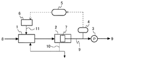
図1の当該汚水浄化処理装置は、膜分離活性汚泥法によりポリビニルアルコール(PVA)を含有する汚水8を浄化処理する装置であり、処理系内に栄養剤11を添加する栄養剤添加機構6を備える。また、当該汚水浄化処理装置は、汚水8を微生物により処理する曝気槽1を備え、栄養剤添加機構6が曝気槽1に付設されている。また、当該汚水浄化処理装置は、曝気槽1で浄化された汚水8を、汚泥10と処理水9とに固液分離する膜分離槽2を備える。また、当該汚水浄化処理装置は、処理後の処理水9の窒素量及び化学的酸素要求量(COD)を測定する測定部4をさらに備え、測定部4で得られた窒素量に基づき栄養剤11の添加量を調整する調整部5を備える。
<Sewage purification equipment>
The sewage purification treatment apparatus in FIG. 1 is an apparatus that purifies
(曝気槽)
上記曝気槽1には好気性の微生物を含む汚泥が保持されており、曝気槽1に接続される汚水管を介して汚水8が曝気槽1内に導入される。続いて、曝気槽1において汚水8が生物学的に処理されて処理水9が生成される。曝気槽1は、処理液管によって膜分離槽2に接続されており、曝気槽1において生物学的に処理された水が汚泥を含んだ状態で、処理液管を介して膜分離槽2に供給される。なお、曝気槽1に導入される汚水8は、PVAが含まれている工業廃水である。
(Aeration tank)
The aeration tank 1 holds sludge containing aerobic microorganisms, and
(膜分離槽)
上記膜分離槽2には分離膜7が液中に浸漬されて設けられている。膜分離槽2は、この分離膜7により汚泥10と処理水9とを固液分離する。膜分離槽2は、汚泥返送管によって曝気槽1に接続されており、分離膜7によって分離された汚泥10は、汚泥返送管を介して曝気槽1へ返送される。また、余剰の汚泥10は、汚泥返送管から引き抜かれる。また、分離膜7によって分離された処理水9は、吸引ポンプ3によって当該汚水浄化処理装置外へ排出される。
(Membrane separation tank)
A
分離膜7としては、通常MBRに使用される膜であれば特に限定されず、精密濾過膜(MF膜)又は限外濾過膜(UF膜)を用いることができる。具体的には、分離膜7として、ポリエチレン、ポリプロピレン、塩素化ポリエチレン等のポリオレフィン系樹脂、ポリフッ化ビニリデン系樹脂、ポリ四弗化エチレン樹脂、ポリスチレン、ポリアクリロニトリル、酢酸セルロース、ポリスルホン、ポリエーテルスルホン、セラミック等から形成された多孔質膜等を用いることができる。
The
また、分離膜7の形態は、平膜又は中空糸膜のいずれの形態であってもよい。平膜とは、平面状又はシート状に成形した膜である。中空糸膜とは、内部が内径3mm程度以下の空洞である糸状の膜である。
Further, the form of the
なお、膜分離槽2の底部には散気管を設けて、分離膜7を曝気洗浄できるようにしている。
An aeration tube is provided at the bottom of the
(栄養剤添加機構)
上記栄養剤添加機構6は、栄養剤11を曝気槽1内へ連続添加する。栄養剤添加機構6から曝気槽1へ添加する栄養剤11の添加量は、調整部5によって制御される。
(Nutrient addition mechanism)
The nutrient
汚泥10には、PVA分解に関与する微生物であるPseudomonas属又はXanthomonas属等の細菌などが含まれている。ここでは、これらの細菌を「PVA分解菌」と呼ぶ。栄養剤11を曝気槽1又は膜分離槽2へ添加することにより、PVA分解菌の活性が上がり、汚水8中のPVA成分の分解が促進される。これにより、未分解のPVAが低減されるので、上記膜分離槽2の分離膜7の膜面への未分解のPVAの付着が低減され、分離膜7の膜差圧の上昇が抑制される。その結果、分離膜7の分離性能の低下が抑制される。
The
上記栄養剤添加機構6が添加する栄養剤11は、窒素を含有する窒素化合物である尿素、アンモニア、モノエタノールアミン、アミノ酸、硫酸アンモニウム、塩化アンモニウム、硝酸アンモニウム、テトラメチルアンモニウムヒドロキシド等である。栄養剤11には、DAP(Diammonium phosphate;リン酸水素二アンモニウム)等のリン成分が少量添加されていてもよい。
The
(測定部)
上記測定部4は、膜分離槽2から排出される処理水9の一部を採取し、処理水9の窒素量を測定し、その測定結果を調整部5へ通知する。また、上記測定部4は、処理水9のCODも測定して、その測定結果を調整部5へ通知する。
(Measurement part)
The measurement unit 4 collects a part of the treated
なお、図1では、測定部4が、膜分離槽2から排出される処理水9を測定する構成としているが、膜分離槽2内の処理水9の窒素量及びCODを測定する構成としてもよいし、吸引ポンプ3から排出された後の処理水9の窒素量及びCODを測定する構成としてもよい。
In FIG. 1, the measurement unit 4 is configured to measure the treated
(調整部)
上記調整部5は、当該汚水浄化処理装置の運転開始時には、曝気槽1へ導入される汚水8のCODに対して過剰の量の栄養剤11を添加するように、栄養剤添加機構6を制御する。運転開始時に、栄養剤添加機構6から過剰に添加させる栄養剤11の量の下限としては、汚水8のCODに対して窒素換算で5%の量が好ましく、10%の量がより好ましい。また、このとき過剰に添加させる栄養剤11の量の上限としては、汚水8のCODに対して窒素換算で25%の量が好ましく、20%の量がより好ましい。栄養剤11の添加量が上記下限未満であると、当該汚水浄化処理装置の運転開始時におけるPVAの分解量が少なくなり、未分解のPVAが膜分離槽2の分離膜7に付着するおそれがある。また、栄養剤11の添加量が上記上限を超えると、窒素分が汚染物として処理水9に含まれて排水されるおそれがある。
(Adjustment part)
The
また、当該汚水浄化処理装置の運転開始後は、上記調整部5は、測定部4から通知される処理水9の窒素量及びCODに応じて、栄養剤添加機構6が曝気槽1へ添加する栄養剤11の添加量を制御する。具体的には、上記調整部5は、CODの値が低下していることを確認し、そのCOD値に対する窒素量が多い場合には、栄養剤添加機構6が曝気槽1へ添加する栄養剤11の単位時間当たりの添加量を減らすように制御する。そして、栄養剤添加機構6が曝気槽1へ添加する栄養剤11の単位時間当たりの添加量を時間と共に減らしていき、最終的にその添加量が一定値に収斂するように制御する。
In addition, after the start of the operation of the sewage purification apparatus, the adjusting
当該汚水浄化処理装置の運転当初に過剰の量の栄養剤11を曝気槽1に添加することで、速やかにPVA分解菌の菌体濃度が上昇する。菌体濃度が上昇した結果、PVAの分解がより進むようになる。一度PVAの分解が進み始めると、菌体濃度を維持するのに必要な栄養剤があればよいので、栄養剤を過剰に添加する必要がなくなる。そのため、運転開始後は、栄養剤11の添加量を減少させるように制御している。
By adding an excessive amount of
<汚水浄化処理方法>
当該汚水浄化処理方法は、膜分離活性汚泥法によりポリビニルアルコール(PVA)を含有する汚水を浄化処理する方法であって、処理系内に栄養剤11を添加するものである。当該汚水浄化処理方法は、汚水8に曝気する微生物処理工程を有し、この微生物処理工程で栄養剤11の添加を行う。また、当該汚水浄化処理方法は、処理後の窒素量及び化学的酸素要求量(COD)を測定する工程を有し、この測定工程で得られた窒素量に基づき栄養剤11の添加量を調整する。
<Sewage purification method>
The sewage purification treatment method is a method of purifying sewage containing polyvinyl alcohol (PVA) by a membrane separation activated sludge method, and adds a
(微生物処理工程)
上記微生物処理工程では、当該汚水浄化処理装置の運転開始時には、曝気槽1へ汚水8を導入した後、栄養剤添加機構6が、汚水8の化学的酸素要求量(COD)に対して過剰の量の栄養剤11を曝気槽1へ添加する。
(Microbial treatment process)
In the above microbial treatment process, at the start of operation of the sewage purification apparatus, after introducing the
当該汚水浄化処理装置の運転中は、曝気槽1内の汚水8の温度が、PVAの分解が進むのに適切な温度に維持される。このときの曝気槽1内の汚水8の温度の下限としては、25℃が好ましく、27℃がより好ましい。また、このときの曝気槽1内の汚水8の温度の上限としては、38℃が好ましく、35℃がより好ましい。曝気槽1内の汚水8の温度が上記下限未満のときには、PVAが分解されにくくなるおそれがある。また、曝気槽1内の汚水8の温度が上記上限を超えたときにも、PVAが分解されにくくなるおそれがある。具体的には、30℃を目標として曝気槽1内の汚水8の温度を制御するとよい。
During operation of the sewage purification apparatus, the temperature of the
当該汚水浄化処理装置の運転開始後も、継続して栄養剤添加機構6が曝気槽1へ栄養剤11を添加する。このとき、調整部5によって決定される単位時間当たりの量に従って、栄養剤11が栄養剤添加機構6から曝気槽1へ添加される。
The nutrient
栄養剤11が曝気槽1へ添加されることにより、曝気槽1内のPVA分解菌の活性が上がり、汚水8中のPVA成分の分解が促進される。これにより、曝気槽1で浄化された後の処理水9のCODは、汚水8のCODに対して大きく低下する。
By adding the
(COD測定工程)
上記COD測定工程では、測定部4が処理水9の一部を採取し窒素量及びCODを測定する。測定部4は、その測定結果を調整部5へ通知する。
(COD measurement process)
In the COD measurement step, the measurement unit 4 collects a part of the treated
(栄養剤添加量調整工程)
上記栄養剤添加量調整工程では、調整部5が、処理水9のCODが低下していることを確認すると、処理水9の窒素量を低減させるために、栄養剤添加機構6から曝気槽1へ添加する栄養剤11の単位時間当たりの量を時間と共に減らしていくように制御する。このとき、調整部5は、測定部4で測定された窒素量に応じて、曝気槽1へ添加する栄養剤11の単位時間当たりの量を決定する。調整部5は、最終的に栄養剤11の単位時間当たりの添加量が一定値に収斂するように制御する。
(Nutritive additive adjustment process)
In the nutrient solution addition amount adjustment step, when the
このように、当該汚水浄化処理装置は、処理水9の窒素量を過剰な窒素量と考え、CODが低下したことを確認しつつ、注入窒素量が過剰にならないように窒素の注入量(栄養剤11の添加量)を補正している。例えば、調整部5は、処理水9の窒素量が100mg/Lであった場合に栄養剤11の添加量を100mg/L減らすような制御をする。
In this way, the sewage purification treatment apparatus considers the nitrogen amount of the treated
なお、処理水9中に亜硝酸態窒素(NO2−N)が残留している場合には、NO2−Nにより発生するCODを含む値が処理水9のCOD値として計測されるため、調整部5は、NO2−Nにより発生するCODを計算して処理水9のCODの測定値を補正する。
In addition, when nitrite nitrogen (NO 2 —N) remains in the treated
〔利点〕
当該汚水浄化処理装置は、栄養剤添加機構6が曝気槽1へ栄養剤11を添加することにより、PVA分解菌の菌体濃度を上昇させることができ、かつ栄養剤11の添加によりPVA分解菌の活動が活性化されるので、PVAの分解が進み、分離膜のファウリングの発生が抑制される。
〔advantage〕
The sewage purification treatment apparatus can increase the cell concentration of the PVA-degrading bacteria by adding the
また、当該汚水浄化処理装置は、曝気槽1に添加する栄養剤11が窒素を含有しているので、PVAの分解を促進させることができる。
Moreover, since the
また、当該汚水浄化処理装置は、栄養剤11の初期添加量を、汚水8のCODに対して過剰に添加することで、当該汚水浄化処理装置の運転開始時のPVA分解菌の活動を活性化させ、PVAの分解を促進するとともに、その後、処理水9のCOD及び窒素量に応じて添加する栄養剤11の量を制御することにより、PVA分解菌が活性化された状態を維持しながら、処理水の窒素量を減らし、かつCODが低下していることを確認する。
Moreover, the said sewage purification processing apparatus activates the activity of the PVA decomposing bacteria at the time of the operation start of the said sewage purification processing apparatus by adding the initial addition amount of the
〔他の実施形態〕
今回開示された実施形態は、全ての点で例示であって制限的なものではないと考えられるべきである。本発明の範囲は、上記実施形態の構成に限定されるものではなく、特許請求の範囲によって示され、特許請求の範囲と均等の意味及び範囲内での全ての変更が含まれることが意図される。
Other Embodiment
It should be thought that embodiment disclosed this time is an illustration and restrictive at no points. The scope of the present invention is not limited to the configuration of the embodiment described above, but is defined by the scope of the claims, and is intended to include all modifications within the meaning and scope equivalent to the scope of the claims. The
上記実施形態では、汚水8を直接曝気槽1に導入する構成としたが、一般的に用いられるスクリーンにより汚水8に含まれる固形物を分離し、その固形物を除去した後の汚水8を曝気槽1へ導入する構成としてもよい。これにより、固形物の混入による分離膜7のファウリングの発生を予防できる。
In the said embodiment, although it was set as the structure which introduces the
また、上記実施形態では、栄養剤添加機構6によって栄養剤11を自動的に曝気槽1に添加する構成としたが、栄養剤添加機構6ではなく、手動によって栄養剤11を曝気槽1へ投入する構成としてもよい。具体的には、運転開始時は、過剰の量の栄養剤11を手動で薬品袋より取り出して曝気槽1へ投入し、運転開始後は、調整部5によって算出された添加量の栄養剤11を手動で薬品袋より計量して、曝気槽1へ投入する。
In the above embodiment, the
また、上記実施形態では、測定部4を処理系内に常設する構成としたが、例えばハンディメータなどにより処理水9の窒素量及びCODを適時サンプリングする構成としてもよい。
Moreover, in the said embodiment, although it was set as the structure which installs the measurement part 4 in a processing system normally, it is good also as a structure which samples the nitrogen amount and COD of the treated
また、上記実施形態では、栄養剤11を曝気槽1へ添加する構成としたが、栄養剤11を膜分離槽2へ添加する構成としてもよく、また曝気槽1及び膜分離槽2の両方へ添加する構成としてもよい。
Moreover, in the said embodiment, it was set as the structure which adds the
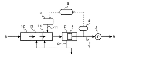
また、上記実施形態では、曝気槽1により汚水8を浄化する構成としたが、図2に示す汚水浄化処理装置のように、嫌気槽12、無酸素槽13及び好気槽14により浄化する構成としてもよい。なお、図2では、図1と同じ構成部分には同じ符号を付し、説明を省略する。図2では、好気槽14に栄養剤11を添加する構成としているが、無酸素槽13に栄養剤11を添加する構成としてもよいし、好気槽14及び無酸素槽13の両方に栄養剤11を添加する構成としてもよい。この構成とすることにより、PVA分解菌をより活性化させることができ、浄化効率を向上させることができる。
Moreover, in the said embodiment, although it was set as the structure which purifies the
また、上記実施形態では、運転開始時に過剰の量の栄養剤11を添加することによりPVA分解菌が活性化し、その後栄養剤11の添加量を減らすことにより処理水9の過剰となった窒素量が低下するが、当該汚水浄化処理装置の処理系内に脱窒層を設けて過剰の窒素を低下させてもよい。
Moreover, in the said embodiment, the amount of nitrogen which became the excess of the treated
また、図1や図2では、膜分離槽2を反応槽とは別に設ける別置型としたが、反応槽内に分離膜を設ける一槽式の構成としてもよい。
In FIG. 1 and FIG. 2, the
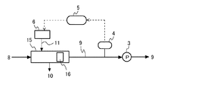
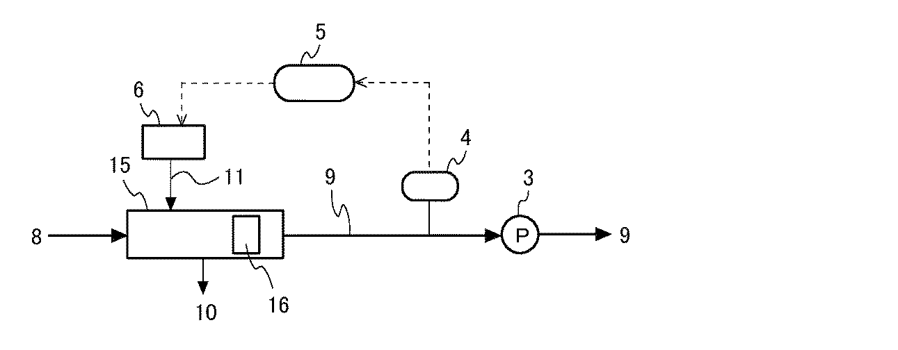
図3に、曝気槽15内に分離膜16を設けた一槽式の汚水浄化処理装置のブロック図を示す。図3では、図1と同じ構成部分には同じ符号を付し、説明を省略する。図3の分離膜16の形態は中空糸膜である。このように一槽式とした場合、分離膜16によって分離した汚泥を反応槽に返送する機構を設ける必要がなく、汚水浄化処理装置を小型で簡単な構造とすることができる。
FIG. 3 is a block diagram of a single tank type sewage purification apparatus in which a
以下、実施例によって本発明をさらに具体的に説明するが、本発明は以下の実施例に限定されるものではない。 EXAMPLES Hereinafter, the present invention will be described more specifically with reference to examples. However, the present invention is not limited to the following examples.
汚水浄化処理装置に導入する汚水として、染色工場の廃水(生物化学的酸素要求量(BOD)濃度390mg/L)を用い、汚水浄化処理装置における水理学的滞留時間を72時間とした。運転開始時には、曝気槽内の活性汚泥を、被処理水の活性汚泥浮遊物質(MLSS)濃度が8000mg/Lとなるように供給した。また、運転中の被処理水のMLSS濃度が7000〜12000mg/Lとなるように、適宜、活性汚泥の引き抜きを行った。 As sewage to be introduced into the sewage purification apparatus, waste water from a dyeing factory (biochemical oxygen demand (BOD) concentration: 390 mg / L) was used, and the hydraulic residence time in the sewage purification apparatus was 72 hours. At the start of operation, the activated sludge in the aeration tank was supplied so that the activated sludge suspended matter (MLSS) concentration of the water to be treated was 8000 mg / L. Further, the activated sludge was appropriately extracted so that the MLSS concentration of the water to be treated during operation was 7000 to 12000 mg / L.
[実施例1]
図1に示す膜分離活性汚泥法による汚水浄化処理装置を用いて上記汚水の浄化処理を行った。膜分離槽の分離膜として、公称孔径0.1μmのポリフッ化ビニリデン(PVDF)の精密ろ過膜を装着した中空糸膜エレメントを用いた。
[Example 1]
The sewage purification treatment was performed using the sewage purification treatment apparatus by the membrane separation activated sludge method shown in FIG. As the separation membrane of the membrane separation tank, a hollow fiber membrane element equipped with a microfiltration membrane of polyvinylidene fluoride (PVDF) having a nominal pore diameter of 0.1 μm was used.
運転開始時に、汚水のCOD(1100mg/L)の20%の窒素分を含む尿素を栄養剤として曝気槽に添加した。運転開始後は、膜分離槽で分離された後の処理水のCOD及び窒素量に応じて栄養剤の単位時間当たりの添加量を低減しながら、継続して栄養剤を曝気槽へ添加した。運転中、曝気槽内及び膜分離槽内の水温は、30℃に維持した。 At the start of operation, urea containing 20% nitrogen content of COD (1100 mg / L) of sewage was added as a nutrient to the aeration tank. After the start of operation, the nutrient solution was continuously added to the aeration tank while the amount of nutrient solution added per unit time was reduced according to the COD and nitrogen content of the treated water separated in the membrane separation tank. During operation, the water temperature in the aeration tank and the membrane separation tank was maintained at 30 ° C.
[比較例1]
従来の活性汚泥法により、上記汚水の浄化処理を行った。すなわち、汚水を曝気槽で浄化した後、その曝気槽で浄化した水を沈殿池に供給し、沈殿池で活性汚泥を自然に沈降させて上澄み液と分離し、その上澄み液を処理水として得た。
[Comparative Example 1]
The sewage was purified by a conventional activated sludge method. In other words, after purifying the sewage water in the aeration tank, the water purified in the aeration tank is supplied to the sedimentation basin, the activated sludge is naturally settled in the sedimentation basin and separated from the supernatant liquid, and the supernatant liquid is obtained as treated water. It was.
[比較例2]
実施例1と同様の膜分離活性汚泥法による汚水浄化処理装置を用いて、栄養剤を曝気槽へ添加せずに上記汚水の浄化処理を行った。実施例1とは、栄養剤を添加しない点のみが異なる。
[Comparative Example 2]
Using the same sewage purification treatment apparatus by the membrane separation activated sludge method as in Example 1, the sewage purification treatment was performed without adding the nutrient to the aeration tank. This example differs from Example 1 only in that no nutrient is added.
(BODの測定)
上記実施例1及び比較例2について、24日間以上運転した後の汚水浄化処理装置から排出される処理水のBODをJIS K−0102(工場排水試験方法)に沿って測定した。
(Measurement of BOD)
About the said Example 1 and the comparative example 2, the BOD of the treated water discharged | emitted from the sewage purification processing apparatus after driving | running for 24 days or more was measured according to JISK-0102 (factory drainage test method).
(CODの測定)
上記実施例1、比較例1及び比較例2について、24日間以上運転した後の汚水浄化処理装置から排出される処理水のCODをJIS K−0102(工場排水試験方法)に沿って測定した。実施例1及び比較例2については、膜分離槽内の水のCODも求めた。実施例1及び比較例2では、膜分離槽中の浮遊物質(SS)を1μm濾紙にて濾過した濾過水を分析してCODを求めた。
(Measurement of COD)
About the said Example 1, the comparative example 1, and the comparative example 2, COD of the treated water discharged | emitted from the sewage purification processing apparatus after operating for 24 days or more was measured according to JISK-0102 (factory waste water test method). For Example 1 and Comparative Example 2, the COD of water in the membrane separation tank was also determined. In Example 1 and Comparative Example 2, COD was obtained by analyzing the filtered water obtained by filtering the suspended matter (SS) in the membrane separation tank with a 1 μm filter paper.
(PVAの測定)
上記実施例1、比較例1及び比較例2について、24日間以上運転した後の汚水浄化処理装置から排出される処理水中のPVAを硼酸添加沃素比色法により測定した。実施例1及び比較例2については、膜分離槽内の水中のPVAも求めた。
(Measurement of PVA)
For Example 1, Comparative Example 1 and Comparative Example 2, PVA in the treated water discharged from the sewage purification apparatus after operating for 24 days or more was measured by a boric acid-added iodine colorimetric method. For Example 1 and Comparative Example 2, PVA in water in the membrane separation tank was also determined.
表1に、これらの測定結果を示す。表1には、上記実施例1、比較例1及び比較例2の汚水浄化処理装置に導入した汚水(原水)についての測定値も示す。なお、表1において、「栄養剤添加MBR」とは実施例1の汚水浄化処理装置を示し、「活性汚泥法沈殿池」とは比較例1の従来の活性汚泥法による汚水浄化処理装置の沈殿池を示し、「栄養剤添加なしMBR」とは比較例2の汚水浄化処理装置を示している。 Table 1 shows the measurement results. Table 1 also shows measured values for sewage (raw water) introduced into the sewage purification apparatus of Example 1, Comparative Example 1 and Comparative Example 2. In Table 1, “nutrient-added MBR” refers to the sewage purification apparatus of Example 1, and “activated sludge process sedimentation pond” refers to the sedimentation of the sewage purification process apparatus by the conventional activated sludge process of Comparative Example 1. The pond is shown, and “MBR without nutrient addition” indicates the sewage purification apparatus of Comparative Example 2.
なお、表1に記載の「<1」は、測定装置の最小計測値以下であったことを示すものであり、実施例1のBODが1mg/L以下であったことを示している。また、表1において、MBRの膜分離槽内のBOD、及び従来の活性汚泥法の沈殿池のBODは、測定していないことを示している。 In addition, “<1” described in Table 1 indicates that the measurement value was equal to or less than the minimum measurement value of the measurement apparatus, and indicates that the BOD of Example 1 was 1 mg / L or less. Moreover, in Table 1, it has shown that BOD in the membrane separation tank of MBR and the BOD of the sedimentation basin of the conventional activated sludge method are not measured.
また、原水、膜分離槽内の水、各汚水浄化処理装置で処理された処理水について、水温及びpH値も測定したが、水温は、いずれも20℃以上30℃以下の範囲内の温度であり、pH値は、いずれも7.5以上8.6以下の範囲内の値であった。 Moreover, although the water temperature and pH value were also measured about raw water, the water in a membrane separation tank, and the treated water processed with each sewage purification processing apparatus, all water temperature is the temperature in the range of 20 degreeC or more and 30 degrees C or less. The pH value was a value in the range of 7.5 to 8.6.
表1の結果より、膜分離活性汚泥法(MBR法)による汚水浄化処理装置を用いた場合は、従来の沈殿法による汚水浄化処理装置を用いた場合に比べて、COD及びPVAが共に小さく、膜分離活性汚泥法(MBR法)を用いることにより処理水のCOD及びPVAを大きく低減できることがわかる。 From the results of Table 1, when using the sewage purification treatment apparatus by the membrane separation activated sludge method (MBR method), both COD and PVA are smaller than when using the conventional sewage purification treatment apparatus by the precipitation method, It can be seen that COD and PVA of treated water can be greatly reduced by using the membrane separation activated sludge method (MBR method).
MBRにおける栄養剤の添加の有無についてみると、栄養剤を添加しない場合に比べて、栄養剤を添加した場合のCODが低下しており、PVAについては著しく(1/10以下に)低下していることがわかる。窒素を含有する尿素を栄養剤として添加したことにより、PVA分解菌の活性が上がりPVA成分の分解が促進されたためであり、栄養剤の添加がPVAの分解の促進に大きく影響を与えていることがわかる。 As for the presence or absence of addition of nutrients in MBR, COD when nutrients are added is lower than when no nutrients are added, and PVA is significantly reduced (below 1/10). I understand that. This is because the addition of nitrogen-containing urea as a nutrient enhances the activity of PVA-degrading bacteria and promotes the degradation of PVA components, and the addition of nutrients greatly affects the promotion of PVA degradation. I understand.
また、栄養剤の添加の有無を異ならせたMBRの場合について、汚水浄化処理装置の運転前後における分離膜の膜差圧を確認したところ、栄養剤を添加した場合には、汚水浄化処理装置の運転前後において分離膜の膜差圧の変化が確認できなかったのに対し、栄養剤を添加しなかった場合には、運転後の膜差圧が、運転前の膜差圧に比べて0.34kPa/d上昇していた。これは、栄養剤を添加しなかった場合には、未分解のPVAが膜一次側に濃縮し分離膜に付着したと考えられ、この結果から、栄養剤の添加により分離膜のファウリングの発生を予防できるといえる。 In addition, in the case of MBR with or without the addition of nutrients, the membrane differential pressure of the separation membrane before and after the operation of the sewage purification treatment device was confirmed. When nutrients were added, the sewage purification treatment device Whereas no change in the membrane differential pressure of the separation membrane was observed before and after the operation, when no nutrient was added, the membrane differential pressure after the operation was 0. 0 compared to the membrane differential pressure before the operation. It was increased by 34 kPa / d. This is because when no nutrient was added, undegraded PVA was concentrated on the primary side of the membrane and adhered to the separation membrane. From this result, the occurrence of fouling of the separation membrane by the addition of the nutrient Can be prevented.
<栄養剤添加量による影響の検討>
実施例1では、運転開始から14日経過後以降は、栄養剤の添加量が、1時間当たり汚水のCODの5〜10%の窒素分を含む量に収斂した。
<Examination of the effects of added nutrients>
In Example 1, after the elapse of 14 days from the start of operation, the amount of nutrient added was converged to an amount containing 5 to 10% nitrogen content of COD of sewage per hour.
実施例1において、運転開始時の栄養剤の添加量を汚水のCODの20%の窒素分を含む量としたところ、運転開始から14日経過後以降に、栄養剤の添加量が、1時間当たり汚水のCODの5〜10%の窒素分を含む量に収斂した。この場合、運転開始から14日経過後の処理水のPVAは9mg/Lであり、実施例1と同様のPVAの低下があった。 In Example 1, when the amount of nutrient added at the start of operation was set to an amount containing 20% of nitrogen in the COD of sewage, the amount of nutrient added per hour after the lapse of 14 days from the start of operation. It was converged to an amount containing 5 to 10% of the COD of the sewage. In this case, the PVA of the treated water after 14 days from the start of operation was 9 mg / L, and there was a decrease in PVA as in Example 1.
本発明の汚水浄化処理方法及び汚水浄化処理装置は、上述のようにPVAの分解を促進させ、ファウリングの発生を抑制し、PVAの処理状態を良好に持続させることができるので、例えば、PVAを含む工業廃水等が多量に含まれる汚水を処理する汚水浄化処理装置等として好適に用いられる。 Since the sewage purification treatment method and the sewage purification treatment apparatus of the present invention can promote the decomposition of PVA as described above, suppress the occurrence of fouling, and maintain the treatment state of PVA well, for example, PVA It is suitably used as a sewage purification treatment apparatus for treating sewage containing a large amount of industrial wastewater and the like.
1 曝気槽
2 膜分離槽
3 吸引ポンプ
4 測定部
5 調整部
6 栄養剤添加機構
7 分離膜
8 汚水
9 処理水
10 汚泥
11 栄養剤
12 嫌気槽
13 無酸素槽
14 好気槽
15 曝気槽
16 分離膜
DESCRIPTION OF SYMBOLS 1
Claims (10)
処理系内に栄養剤を添加する汚水浄化処理方法。 A method of purifying sewage containing polyvinyl alcohol by a membrane separation activated sludge method (MBR method),
A sewage purification method of adding a nutrient to the treatment system.
上記栄養剤の添加を上記微生物処理工程で行う請求項1に記載の汚水浄化処理方法。 Having a microbial treatment step for aeration of the sewage,
The sewage purification method according to claim 1, wherein the nutrient is added in the microorganism treatment step.
この測定工程で得られた窒素量に基づき栄養剤の添加量を調整する請求項1、請求項2又は請求項3に記載の汚水浄化処理方法。 Having a step of measuring the amount of nitrogen after treatment;
The sewage purification treatment method according to claim 1, wherein the amount of nutrient added is adjusted based on the amount of nitrogen obtained in the measurement step.
処理系内に栄養剤を添加する機構を備える汚水浄化処理装置。 An apparatus for purifying sewage containing polyvinyl alcohol by a membrane separation activated sludge method,
A sewage purification treatment apparatus having a mechanism for adding a nutrient to a treatment system.
上記曝気槽に栄養剤添加機構が付設されている請求項6に記載の汚水浄化処理装置。 An aeration tank for treating the wastewater with microorganisms;
The sewage purification apparatus according to claim 6, wherein a nutrient solution addition mechanism is attached to the aeration tank.
上記測定部で得られた窒素量に基づき栄養剤の添加量を調整する請求項6、請求項7又は請求項8に記載の汚水浄化処理装置。 It further comprises a measuring unit for measuring the nitrogen amount after treatment and the chemical oxygen demand,
The sewage purification processing apparatus according to claim 6, 7, or 8, wherein the amount of nutrient added is adjusted based on the amount of nitrogen obtained by the measurement unit.
Priority Applications (4)
| Application Number | Priority Date | Filing Date | Title |
|---|---|---|---|
| JP2013141156A JP2015013255A (en) | 2013-07-04 | 2013-07-04 | Sewage purification treatment method and sewage purification treatment apparatus |
| US14/765,088 US20150368130A1 (en) | 2013-07-04 | 2014-06-30 | Process for purification treatment of wastewater and apparatus for purification treatment of wastewater |
| PCT/JP2014/067316 WO2015002121A1 (en) | 2013-07-04 | 2014-06-30 | Process for purification treatment of wastewater and apparatus for purification treatment of wastewater |
| CN201480007066.1A CN104981437A (en) | 2013-07-04 | 2014-06-30 | Sewage purification treatment method and sewage purification treatment device |
Applications Claiming Priority (1)
| Application Number | Priority Date | Filing Date | Title |
|---|---|---|---|
| JP2013141156A JP2015013255A (en) | 2013-07-04 | 2013-07-04 | Sewage purification treatment method and sewage purification treatment apparatus |
Publications (1)
| Publication Number | Publication Date |
|---|---|
| JP2015013255A true JP2015013255A (en) | 2015-01-22 |
Family
ID=52143697
Family Applications (1)
| Application Number | Title | Priority Date | Filing Date |
|---|---|---|---|
| JP2013141156A Pending JP2015013255A (en) | 2013-07-04 | 2013-07-04 | Sewage purification treatment method and sewage purification treatment apparatus |
Country Status (4)
| Country | Link |
|---|---|
| US (1) | US20150368130A1 (en) |
| JP (1) | JP2015013255A (en) |
| CN (1) | CN104981437A (en) |
| WO (1) | WO2015002121A1 (en) |
Families Citing this family (3)
| Publication number | Priority date | Publication date | Assignee | Title |
|---|---|---|---|---|
| CN108928999A (en) * | 2018-08-13 | 2018-12-04 | 武汉新天达美环境科技股份有限公司 | A kind of purifying treatment method for basin sewage |
| CN109052819A (en) * | 2018-08-13 | 2018-12-21 | 武汉新天达美环境科技股份有限公司 | A kind of sewage water treatment method efficiently utilized convenient for algae resource |
| CN118420102A (en) * | 2023-08-31 | 2024-08-02 | 芬欧汇川(中国)有限公司 | Method for adding activated sludge nutrients |
Citations (6)
| Publication number | Priority date | Publication date | Assignee | Title |
|---|---|---|---|---|
| JPS4820352B1 (en) * | 1968-03-22 | 1973-06-20 | ||
| JPS51127569A (en) * | 1975-04-25 | 1976-11-06 | Kuraray Co Ltd | Waste water treatment method |
| JPH09276890A (en) * | 1996-04-15 | 1997-10-28 | Ebara Corp | Method for treating organic wastewater containing polyvinyl alcohol |
| JP2006180706A (en) * | 2003-03-10 | 2006-07-13 | Ip Bio Corp | New polyvinyl alcohol-degrading bacterium |
| JP2006181393A (en) * | 2003-03-10 | 2006-07-13 | Ip Bio Corp | Non-sludge high-speed wastewater treatment system |
| JP2008188552A (en) * | 2007-02-07 | 2008-08-21 | Iib:Kk | Method and device for treating organic waste |
Family Cites Families (7)
| Publication number | Priority date | Publication date | Assignee | Title |
|---|---|---|---|---|
| JPS5172150A (en) * | 1974-12-18 | 1976-06-22 | Kuraray Co | HORIBINIRUARUKOORUKEIJUSHIGANJUHAISUINO SHORIHO |
| KR100513931B1 (en) * | 2003-11-06 | 2005-09-08 | 한국생산기술연구원 | Microorganism for Polyvinyl Alcohol Treatment and A Method for Increasing Biological Treatment Efficient of PVA Containing Wastewater |
| CN101028956A (en) * | 2007-02-06 | 2007-09-05 | 北京工业大学 | Controller for multi-section water-inlet A/O biological denitrifying dissolved oxygen and carbon-source feed |
| WO2010020002A1 (en) * | 2008-08-20 | 2010-02-25 | Ziltek Pty Ltd | Aeration device for use in a biopele |
| CN201381251Y (en) * | 2009-03-06 | 2010-01-13 | 北京倍尼尔科技发展有限公司 | Biochemical reaction tank for treating organic wastewater |
| CN102381804A (en) * | 2010-09-01 | 2012-03-21 | 东丽纤维研究所(中国)有限公司 | Process for recycling printing and dyeing wastewater |
| CN102557275B (en) * | 2010-12-10 | 2014-11-05 | 上海洗霸科技股份有限公司 | Phosphorus-free compound water treatment agent |
-
2013
- 2013-07-04 JP JP2013141156A patent/JP2015013255A/en active Pending
-
2014
- 2014-06-30 CN CN201480007066.1A patent/CN104981437A/en active Pending
- 2014-06-30 WO PCT/JP2014/067316 patent/WO2015002121A1/en not_active Ceased
- 2014-06-30 US US14/765,088 patent/US20150368130A1/en not_active Abandoned
Patent Citations (6)
| Publication number | Priority date | Publication date | Assignee | Title |
|---|---|---|---|---|
| JPS4820352B1 (en) * | 1968-03-22 | 1973-06-20 | ||
| JPS51127569A (en) * | 1975-04-25 | 1976-11-06 | Kuraray Co Ltd | Waste water treatment method |
| JPH09276890A (en) * | 1996-04-15 | 1997-10-28 | Ebara Corp | Method for treating organic wastewater containing polyvinyl alcohol |
| JP2006180706A (en) * | 2003-03-10 | 2006-07-13 | Ip Bio Corp | New polyvinyl alcohol-degrading bacterium |
| JP2006181393A (en) * | 2003-03-10 | 2006-07-13 | Ip Bio Corp | Non-sludge high-speed wastewater treatment system |
| JP2008188552A (en) * | 2007-02-07 | 2008-08-21 | Iib:Kk | Method and device for treating organic waste |
Also Published As
| Publication number | Publication date |
|---|---|
| CN104981437A (en) | 2015-10-14 |
| US20150368130A1 (en) | 2015-12-24 |
| WO2015002121A1 (en) | 2015-01-08 |
Similar Documents
| Publication | Publication Date | Title |
|---|---|---|
| JP5194771B2 (en) | Biological treatment method and apparatus for water containing organic matter | |
| JP5358886B2 (en) | Biological treatment method of water containing organic matter | |
| CN101274800A (en) | Membrane Separation Activated Sludge Plant | |
| TWI596063B (en) | Method for treating organic waste water and treating waste containing organic matter | |
| WO2012079288A1 (en) | Process, apparatus and membrane bioreactor for wastewater treatment | |
| JPWO2009090725A1 (en) | Outside-tank membrane separation activated sludge method | |
| JP5034778B2 (en) | Membrane separation wastewater treatment method and apparatus | |
| TW593166B (en) | Apparatus for reduction of biological wasted sludge | |
| CN102730824A (en) | Processing method of organic water discharge by membrane separation activated sludge device | |
| JP2012206039A (en) | Treatment apparatus of organic matter containing wastewater | |
| WO2011136043A1 (en) | Wastewater treatment device and wastewater treatment method | |
| WO2015002121A1 (en) | Process for purification treatment of wastewater and apparatus for purification treatment of wastewater | |
| RU2644904C1 (en) | Method of biological purification of wastewater from nitrogen phosphoric and organic compounds | |
| JP2014008431A (en) | Method and apparatus for anaerobic digestion treatment of organic wastewater | |
| JP6721288B2 (en) | Wastewater treatment method and wastewater treatment system | |
| JP2015160202A (en) | Method and apparatus for biological treatment of 1,4-dioxane-containing organic waste water | |
| JP2009189943A (en) | Water treatment method and apparatus | |
| JP2001047089A (en) | Wastewater treatment method and treatment device | |
| KR20030097075A (en) | Hybrid Submerged Plate Type Membrane Bioreactor Using microfilter Combined With Biofilm-Activated Carbon for Advanced Treatment of Sewage and Wastewater | |
| JP2014213265A (en) | Method and device for biologically treating organic matter-containing water | |
| JP5817177B2 (en) | Organic wastewater treatment equipment | |
| KR20010109804A (en) | Treatment of concentrated organic wastewater with a reverse osmosis process | |
| KR102059988B1 (en) | Membrane water treatment apparatus using micro-bubble | |
| KR20160050683A (en) | Method for reducing membrane fouling in the water treatment apparatus | |
| JP6365714B1 (en) | Aerobic treatment method |
Legal Events
| Date | Code | Title | Description |
|---|---|---|---|
| A621 | Written request for application examination |
Free format text: JAPANESE INTERMEDIATE CODE: A621 Effective date: 20160518 |
|
| A131 | Notification of reasons for refusal |
Free format text: JAPANESE INTERMEDIATE CODE: A131 Effective date: 20161220 |
|
| A02 | Decision of refusal |
Free format text: JAPANESE INTERMEDIATE CODE: A02 Effective date: 20170627 |