JP2014518694A - Furniture equipment and kits, systems and their use - Google Patents
Furniture equipment and kits, systems and their use Download PDFInfo
- Publication number
- JP2014518694A JP2014518694A JP2014508655A JP2014508655A JP2014518694A JP 2014518694 A JP2014518694 A JP 2014518694A JP 2014508655 A JP2014508655 A JP 2014508655A JP 2014508655 A JP2014508655 A JP 2014508655A JP 2014518694 A JP2014518694 A JP 2014518694A
- Authority
- JP
- Japan
- Prior art keywords
- connector
- diatomaceous earth
- dependent
- decorative cover
- main body
- Prior art date
- Legal status (The legal status is an assumption and is not a legal conclusion. Google has not performed a legal analysis and makes no representation as to the accuracy of the status listed.)
- Pending
Links
- VYPSYNLAJGMNEJ-UHFFFAOYSA-N Silicium dioxide Chemical compound O=[Si]=O VYPSYNLAJGMNEJ-UHFFFAOYSA-N 0.000 claims abstract description 113
- 239000005909 Kieselgur Substances 0.000 claims abstract description 108
- 229920001169 thermoplastic Polymers 0.000 claims abstract description 38
- 239000004416 thermosoftening plastic Substances 0.000 claims abstract description 38
- 230000000295 complement effect Effects 0.000 claims abstract description 21
- 108090000765 processed proteins & peptides Proteins 0.000 claims abstract description 6
- 206010004194 Bed bug infestation Diseases 0.000 claims description 58
- 241001414835 Cimicidae Species 0.000 claims description 56
- OKTJSMMVPCPJKN-UHFFFAOYSA-N Carbon Chemical compound [C] OKTJSMMVPCPJKN-UHFFFAOYSA-N 0.000 claims description 13
- 241001465754 Metazoa Species 0.000 claims description 13
- 229910052799 carbon Inorganic materials 0.000 claims description 13
- 239000011347 resin Substances 0.000 claims description 13
- 229920005989 resin Polymers 0.000 claims description 13
- 241000238631 Hexapoda Species 0.000 claims description 12
- 238000003860 storage Methods 0.000 claims description 12
- 238000000034 method Methods 0.000 claims description 11
- 239000001397 quillaja saponaria molina bark Substances 0.000 claims description 5
- 229930182490 saponin Natural products 0.000 claims description 5
- 229910018072 Al 2 O 3 Inorganic materials 0.000 claims description 4
- 241000238421 Arthropoda Species 0.000 claims description 4
- 229910004298 SiO 2 Inorganic materials 0.000 claims description 4
- 230000008878 coupling Effects 0.000 claims description 4
- 238000010168 coupling process Methods 0.000 claims description 4
- 238000005859 coupling reaction Methods 0.000 claims description 4
- 230000013011 mating Effects 0.000 claims description 4
- 239000002245 particle Substances 0.000 claims description 4
- 150000007949 saponins Chemical class 0.000 claims description 4
- 239000002002 slurry Substances 0.000 claims description 4
- XLYOFNOQVPJJNP-UHFFFAOYSA-N water Substances O XLYOFNOQVPJJNP-UHFFFAOYSA-N 0.000 claims description 3
- 241000239290 Araneae Species 0.000 claims description 2
- 230000001419 dependent effect Effects 0.000 claims 24
- 238000005259 measurement Methods 0.000 claims 1
- 230000003014 reinforcing effect Effects 0.000 description 35
- 239000012815 thermoplastic material Substances 0.000 description 14
- 241001327638 Cimex lectularius Species 0.000 description 13
- 238000002474 experimental method Methods 0.000 description 11
- 239000000463 material Substances 0.000 description 11
- 239000000284 extract Substances 0.000 description 10
- 235000021374 legumes Nutrition 0.000 description 10
- 239000004744 fabric Substances 0.000 description 9
- 239000000443 aerosol Substances 0.000 description 6
- 239000003351 stiffener Substances 0.000 description 6
- 241000607479 Yersinia pestis Species 0.000 description 4
- 239000010409 thin film Substances 0.000 description 4
- QTBSBXVTEAMEQO-UHFFFAOYSA-N Acetic acid Chemical compound CC(O)=O QTBSBXVTEAMEQO-UHFFFAOYSA-N 0.000 description 3
- 239000000654 additive Substances 0.000 description 3
- 239000000428 dust Substances 0.000 description 3
- 238000010438 heat treatment Methods 0.000 description 3
- 239000002917 insecticide Substances 0.000 description 3
- 239000007791 liquid phase Substances 0.000 description 3
- 229930014626 natural product Natural products 0.000 description 3
- 230000036961 partial effect Effects 0.000 description 3
- 239000004033 plastic Substances 0.000 description 3
- 229920003023 plastic Polymers 0.000 description 3
- 230000002787 reinforcement Effects 0.000 description 3
- 230000010076 replication Effects 0.000 description 3
- 241000239223 Arachnida Species 0.000 description 2
- 240000002853 Nelumbo nucifera Species 0.000 description 2
- 235000006508 Nelumbo nucifera Nutrition 0.000 description 2
- 235000006510 Nelumbo pentapetala Nutrition 0.000 description 2
- 230000000996 additive effect Effects 0.000 description 2
- 238000007605 air drying Methods 0.000 description 2
- 230000008859 change Effects 0.000 description 2
- 238000005034 decoration Methods 0.000 description 2
- 238000013461 design Methods 0.000 description 2
- 238000001035 drying Methods 0.000 description 2
- 230000007613 environmental effect Effects 0.000 description 2
- 239000007850 fluorescent dye Substances 0.000 description 2
- 229910052500 inorganic mineral Inorganic materials 0.000 description 2
- 230000002147 killing effect Effects 0.000 description 2
- 231100000636 lethal dose Toxicity 0.000 description 2
- 238000004519 manufacturing process Methods 0.000 description 2
- 239000011707 mineral Substances 0.000 description 2
- 239000000575 pesticide Substances 0.000 description 2
- 238000005498 polishing Methods 0.000 description 2
- -1 polypropylene Polymers 0.000 description 2
- 230000002829 reductive effect Effects 0.000 description 2
- 230000000007 visual effect Effects 0.000 description 2
- 239000002699 waste material Substances 0.000 description 2
- ONAAMCDHQSWPDU-BKUHCKHBSA-N (2s,3s,4s,5r,6r)-6-[[(3s,4s,4ar,6ar,6bs,8ar,9r,12as,14ar,14br)-4-(hydroxymethyl)-9-[[(2r)-5-hydroxy-6-methyl-4-oxo-2,3-dihydropyran-2-yl]oxy]-4,6a,6b,8a,11,11,14b-heptamethyl-1,2,3,4a,5,6,7,8,9,10,12,12a,14,14a-tetradecahydropicen-3-yl]oxy]-5-[(2s,3r,4s,5 Chemical compound O[C@@H]1[C@H](O)[C@@H](O)[C@H](C)O[C@H]1O[C@H]1[C@H](O[C@H]2[C@@H](O[C@@H]([C@@H](O)[C@@H]2O)C(O)=O)O[C@@H]2[C@]([C@H]3[C@]([C@@H]4[C@@]([C@@]5(CC[C@@]6(C)[C@H](O[C@@H]7OC(C)=C(O)C(=O)C7)CC(C)(C)C[C@H]6C5=CC4)C)(C)CC3)(C)CC2)(C)CO)O[C@H](CO)[C@H](O)[C@@H]1O ONAAMCDHQSWPDU-BKUHCKHBSA-N 0.000 description 1
- AXNVHPCVMSNXNP-IVKVKCDBSA-N (2s,3s,4s,5r,6r)-6-[[(3s,4s,4ar,6ar,6bs,8r,8ar,9r,10r,12as,14ar,14br)-9-acetyloxy-8-hydroxy-4,8a-bis(hydroxymethyl)-4,6a,6b,11,11,14b-hexamethyl-10-[(e)-2-methylbut-2-enoyl]oxy-1,2,3,4a,5,6,7,8,9,10,12,12a,14,14a-tetradecahydropicen-3-yl]oxy]-4-hydroxy-3, Chemical compound O([C@@H]1[C@H](O[C@H]([C@@H]([C@H]1O)O[C@H]1[C@@H]([C@@H](O)[C@H](O)[C@@H](CO)O1)O)O[C@H]1CC[C@]2(C)[C@H]3CC=C4[C@@]([C@@]3(CC[C@H]2[C@]1(CO)C)C)(C)C[C@@H](O)[C@@]1(CO)[C@@H](OC(C)=O)[C@@H](C(C[C@H]14)(C)C)OC(=O)C(/C)=C/C)C(O)=O)[C@@H]1O[C@H](CO)[C@@H](O)[C@H](O)[C@H]1O AXNVHPCVMSNXNP-IVKVKCDBSA-N 0.000 description 1
- RNFJDJUURJAICM-UHFFFAOYSA-N 2,2,4,4,6,6-hexaphenoxy-1,3,5-triaza-2$l^{5},4$l^{5},6$l^{5}-triphosphacyclohexa-1,3,5-triene Chemical compound N=1P(OC=2C=CC=CC=2)(OC=2C=CC=CC=2)=NP(OC=2C=CC=CC=2)(OC=2C=CC=CC=2)=NP=1(OC=1C=CC=CC=1)OC1=CC=CC=C1 RNFJDJUURJAICM-UHFFFAOYSA-N 0.000 description 1
- AXNVHPCVMSNXNP-GKTCLTPXSA-N Aescin Natural products O=C(O[C@H]1[C@@H](OC(=O)C)[C@]2(CO)[C@@H](O)C[C@@]3(C)[C@@]4(C)[C@@H]([C@]5(C)[C@H]([C@](CO)(C)[C@@H](O[C@@H]6[C@@H](O[C@H]7[C@@H](O)[C@@H](O)[C@H](O)[C@@H](CO)O7)[C@@H](O)[C@H](O[C@H]7[C@H](O)[C@@H](O)[C@H](O)[C@H](CO)O7)[C@@H](C(=O)O)O6)CC5)CC4)CC=C3[C@@H]2CC1(C)C)/C(=C/C)/C AXNVHPCVMSNXNP-GKTCLTPXSA-N 0.000 description 1
- IBZLICPLPYSFNZ-UHFFFAOYSA-N Astragaloside VIII Natural products OC1C(O)C(O)C(C)OC1OC1C(OC2C(OC(C(O)C2O)C(O)=O)OC2C(C3C(C4C(C5(CCC6(C)C(O)CC(C)(C)CC6C5=CC4)C)(C)CC3)(C)CC2)(C)CO)OCC(O)C1O IBZLICPLPYSFNZ-UHFFFAOYSA-N 0.000 description 1
- KFFJPIQLAPHYBF-UHFFFAOYSA-N Azukisaponin V Natural products COC(=O)C1OC(OC2CCC3(C)C(CCC4(C)C3CC=C5C6CC(C)(C)CC(O)C6(O)CCC45C)C2(C)CO)C(OC7OC(CO)C(O)C(O)C7OC8OC(C)C(O)C(O)C8O)C(O)C1O KFFJPIQLAPHYBF-UHFFFAOYSA-N 0.000 description 1
- 241001674044 Blattodea Species 0.000 description 1
- 241000282836 Camelus dromedarius Species 0.000 description 1
- CTQURVKMWHDOKO-UHFFFAOYSA-N Dehydrosoyasaponin I Natural products CC1OC(OC2C(O)C(O)C(CO)OC2OC3C(O)C(O)C(OC3OC4CCC5(C)C(CCC6(C)C5CC=C7C8CC(C)(C)CC(=O)C8(C)CCC67C)C4(C)C=O)C(=O)O)C(O)C(O)C1O CTQURVKMWHDOKO-UHFFFAOYSA-N 0.000 description 1
- CROUPKILZUPLQA-ITVSDQETSA-N Dehydrosoyasaponin I Chemical compound O[C@@H]1[C@H](O)[C@@H](O)[C@H](C)O[C@H]1O[C@H]1[C@H](O[C@H]2[C@@H](O[C@@H]([C@@H](O)[C@@H]2O)C(O)=O)O[C@@H]2[C@]([C@H]3[C@]([C@@H]4[C@@]([C@@]5(CC[C@@]6(C)C(=O)CC(C)(C)C[C@H]6C5=CC4)C)(C)CC3)(C)CC2)(C)CO)O[C@H](CO)[C@H](O)[C@@H]1O CROUPKILZUPLQA-ITVSDQETSA-N 0.000 description 1
- WYDPEADEZMZKNM-ZBKPBKBGSA-N Echinocystic acid 3-glucoside Chemical compound O([C@H]1CC[C@]2(C)[C@H]3CC=C4[C@@]([C@@]3(CC[C@H]2C1(C)C)C)(C)C[C@@H](O)[C@]1(CCC(C[C@H]14)(C)C)C(O)=O)[C@@H]1O[C@H](CO)[C@@H](O)[C@H](O)[C@H]1O WYDPEADEZMZKNM-ZBKPBKBGSA-N 0.000 description 1
- RYHDIBJJJRNDSX-MCGLQMIESA-N Hederacoside C Chemical compound O[C@@H]1[C@H](O)[C@@H](O)[C@H](C)O[C@H]1O[C@@H]1[C@@H](CO)O[C@@H](OC[C@@H]2[C@H]([C@H](O)[C@@H](O)[C@H](OC(=O)[C@@]34[C@@H](CC(C)(C)CC3)C=3[C@@]([C@]5(C)CC[C@H]6[C@](C)(CO)[C@@H](O[C@H]7[C@@H]([C@@H](O)[C@@H](O)CO7)O[C@H]7[C@@H]([C@H](O)[C@@H](O)[C@H](C)O7)O)CC[C@]6(C)[C@H]5CC=3)(C)CC4)O2)O)[C@H](O)[C@H]1O RYHDIBJJJRNDSX-MCGLQMIESA-N 0.000 description 1
- 241000257303 Hymenoptera Species 0.000 description 1
- VTAJIXDZFCRWBR-UHFFFAOYSA-N Licoricesaponin B2 Natural products C1C(C2C(C3(CCC4(C)CCC(C)(CC4C3=CC2)C(O)=O)C)(C)CC2)(C)C2C(C)(C)CC1OC1OC(C(O)=O)C(O)C(O)C1OC1OC(C(O)=O)C(O)C(O)C1O VTAJIXDZFCRWBR-UHFFFAOYSA-N 0.000 description 1
- 235000010627 Phaseolus vulgaris Nutrition 0.000 description 1
- 244000046052 Phaseolus vulgaris Species 0.000 description 1
- 239000004743 Polypropylene Substances 0.000 description 1
- JFHRJMPZZYINAI-UHFFFAOYSA-N Soyasaponin I Natural products CC1OC(OC2C(O)C(O)C(CO)OC2OC3C(O)C(O)C(CO)OC3OC4CCC5(C)C(CCC6(C)C5CC=C7C8CC(C)(C)CC(O)C8(C)CCC67C)C4(C)CO)C(O)C(O)C1O JFHRJMPZZYINAI-UHFFFAOYSA-N 0.000 description 1
- IBZLICPLPYSFNZ-IVWMTKFPSA-N Soyasaponin II Chemical compound O[C@@H]1[C@H](O)[C@@H](O)[C@H](C)O[C@H]1O[C@H]1[C@H](O[C@H]2[C@@H](O[C@@H]([C@@H](O)[C@@H]2O)C(O)=O)O[C@@H]2[C@]([C@H]3[C@]([C@@H]4[C@@]([C@@]5(CC[C@@]6(C)[C@H](O)CC(C)(C)C[C@H]6C5=CC4)C)(C)CC3)(C)CC2)(C)CO)OC[C@H](O)[C@@H]1O IBZLICPLPYSFNZ-IVWMTKFPSA-N 0.000 description 1
- PZLAZXBSOCTDBG-UHFFFAOYSA-N Soyasaponin II Natural products CC1OC(OC2C(O)C(O)COC2OC3C(O)C(O)C(CO)OC3OC4CCC5(C)C(CCC6(C)C5CC=C7C8CC(C)(C)CC(O)C8(C)CCC67C)C4(C)CO)C(O)C(O)C1O PZLAZXBSOCTDBG-UHFFFAOYSA-N 0.000 description 1
- UZUYQJHHUUDLDJ-UHFFFAOYSA-N Soyasaponin III Natural products CC1(C)CC(O)C2(C)CCC3(C)C(=CCC4C5(C)CCC(OC6OC(CO)C(O)C(O)C6OC7OC(CO)C(O)C(O)C7O)C(C)(CO)C5CCC34C)C2C1 UZUYQJHHUUDLDJ-UHFFFAOYSA-N 0.000 description 1
- 230000001154 acute effect Effects 0.000 description 1
- 210000004712 air sac Anatomy 0.000 description 1
- 239000013566 allergen Substances 0.000 description 1
- 238000004458 analytical method Methods 0.000 description 1
- 230000008901 benefit Effects 0.000 description 1
- AXNVHPCVMSNXNP-BEJCRFBNSA-N beta-escin Natural products CC=C(/C)C(=O)O[C@H]1[C@H](OC(=O)C)[C@]2(CO)[C@H](O)C[C@@]3(C)C(=CC[C@@H]4[C@@]5(C)CC[C@H](O[C@H]6O[C@@H]([C@H](O[C@H]7O[C@H](CO)[C@@H](O)[C@H](O)[C@H]7O)[C@H](O)[C@@H]6O[C@@H]8O[C@H](CO)[C@@H](O)[C@H](O)[C@H]8O)C(=O)O)[C@](C)(CO)[C@@H]5CC[C@@]34C)[C@@H]2CC1(C)C AXNVHPCVMSNXNP-BEJCRFBNSA-N 0.000 description 1
- 229940093314 beta-escin Drugs 0.000 description 1
- 238000004166 bioassay Methods 0.000 description 1
- 230000015572 biosynthetic process Effects 0.000 description 1
- 238000004364 calculation method Methods 0.000 description 1
- 239000003795 chemical substances by application Substances 0.000 description 1
- 239000003086 colorant Substances 0.000 description 1
- 238000004891 communication Methods 0.000 description 1
- 230000018044 dehydration Effects 0.000 description 1
- 238000006297 dehydration reaction Methods 0.000 description 1
- 238000009826 distribution Methods 0.000 description 1
- 230000000694 effects Effects 0.000 description 1
- 235000013601 eggs Nutrition 0.000 description 1
- 210000003746 feather Anatomy 0.000 description 1
- 239000003063 flame retardant Substances 0.000 description 1
- 239000006261 foam material Substances 0.000 description 1
- 235000013305 food Nutrition 0.000 description 1
- LPLVUJXQOOQHMX-UHFFFAOYSA-N glycyrrhetinic acid glycoside Natural products C1CC(C2C(C3(CCC4(C)CCC(C)(CC4C3=CC2=O)C(O)=O)C)(C)CC2)(C)C2C(C)(C)C1OC1OC(C(O)=O)C(O)C(O)C1OC1OC(C(O)=O)C(O)C(O)C1O LPLVUJXQOOQHMX-UHFFFAOYSA-N 0.000 description 1
- UYRUBYNTXSDKQT-UHFFFAOYSA-N glycyrrhizic acid Natural products CC1(C)C(CCC2(C)C1CCC3(C)C2C(=O)C=C4C5CC(C)(CCC5(C)CCC34C)C(=O)O)OC6OC(C(O)C(O)C6OC7OC(O)C(O)C(O)C7C(=O)O)C(=O)O UYRUBYNTXSDKQT-UHFFFAOYSA-N 0.000 description 1
- 239000001685 glycyrrhizic acid Substances 0.000 description 1
- 229960004949 glycyrrhizic acid Drugs 0.000 description 1
- 235000019410 glycyrrhizin Nutrition 0.000 description 1
- LPLVUJXQOOQHMX-QWBHMCJMSA-N glycyrrhizinic acid Chemical compound O([C@@H]1[C@@H](O)[C@H](O)[C@H](O[C@@H]1O[C@@H]1C([C@H]2[C@]([C@@H]3[C@@]([C@@]4(CC[C@@]5(C)CC[C@@](C)(C[C@H]5C4=CC3=O)C(O)=O)C)(C)CC2)(C)CC1)(C)C)C(O)=O)[C@@H]1O[C@H](C(O)=O)[C@@H](O)[C@H](O)[C@H]1O LPLVUJXQOOQHMX-QWBHMCJMSA-N 0.000 description 1
- 230000005484 gravity Effects 0.000 description 1
- 229920001903 high density polyethylene Polymers 0.000 description 1
- 239000004700 high-density polyethylene Substances 0.000 description 1
- 230000005764 inhibitory process Effects 0.000 description 1
- 230000000749 insecticidal effect Effects 0.000 description 1
- RYHDIBJJJRNDSX-UHFFFAOYSA-N kalopanax-saponin B Natural products OC1C(O)C(O)C(C)OC1OC1C(CO)OC(OCC2C(C(O)C(O)C(OC(=O)C34C(CC(C)(C)CC3)C=3C(C5(C)CCC6C(C)(CO)C(OC7C(C(O)C(O)CO7)OC7C(C(O)C(O)C(C)O7)O)CCC6(C)C5CC=3)(C)CC4)O2)O)C(O)C1O RYHDIBJJJRNDSX-UHFFFAOYSA-N 0.000 description 1
- 230000000670 limiting effect Effects 0.000 description 1
- 239000000203 mixture Substances 0.000 description 1
- 239000000419 plant extract Substances 0.000 description 1
- 229920001155 polypropylene Polymers 0.000 description 1
- 238000012545 processing Methods 0.000 description 1
- 230000000135 prohibitive effect Effects 0.000 description 1
- 230000000717 retained effect Effects 0.000 description 1
- 238000007665 sagging Methods 0.000 description 1
- 238000000926 separation method Methods 0.000 description 1
- PTDAHAWQAGSZDD-IOVCITQVSA-N soyasaponin I Chemical compound O[C@@H]1[C@H](O)[C@@H](O)[C@H](C)O[C@H]1O[C@H]1[C@H](O[C@H]2[C@@H](O[C@@H]([C@@H](O)[C@@H]2O)C(O)=O)O[C@@H]2[C@]([C@H]3[C@]([C@@H]4[C@@]([C@@]5(CC[C@@]6(C)[C@H](O)CC(C)(C)C[C@H]6C5=CC4)C)(C)CC3)(C)CC2)(C)CO)O[C@H](CO)[C@H](O)[C@@H]1O PTDAHAWQAGSZDD-IOVCITQVSA-N 0.000 description 1
- OKIHRVKXRCAJFQ-AHBDIROXSA-N soyasaponin III Chemical compound O([C@@H]1[C@@H](O)[C@H](O)[C@H](O[C@H]1O[C@H]1CC[C@]2(C)[C@H]3CC=C4[C@@]([C@@]3(CC[C@H]2[C@]1(CO)C)C)(C)CC[C@@]1(C)[C@H](O)CC(C[C@H]14)(C)C)C(O)=O)[C@@H]1O[C@H](CO)[C@H](O)[C@H](O)[C@H]1O OKIHRVKXRCAJFQ-AHBDIROXSA-N 0.000 description 1
- ONAAMCDHQSWPDU-UHFFFAOYSA-N soybean saponin BeA Natural products OC1C(O)C(O)C(C)OC1OC1C(OC2C(OC(C(O)C2O)C(O)=O)OC2C(C3C(C4C(C5(CCC6(C)C(OC7OC(C)=C(O)C(=O)C7)CC(C)(C)CC6C5=CC4)C)(C)CC3)(C)CC2)(C)CO)OC(CO)C(O)C1O ONAAMCDHQSWPDU-UHFFFAOYSA-N 0.000 description 1
- 230000004083 survival effect Effects 0.000 description 1
- 231100000331 toxic Toxicity 0.000 description 1
- 230000002588 toxic effect Effects 0.000 description 1
- 150000008130 triterpenoid saponins Chemical class 0.000 description 1
- 239000002023 wood Substances 0.000 description 1
Images


Classifications
-
- A—HUMAN NECESSITIES
- A47—FURNITURE; DOMESTIC ARTICLES OR APPLIANCES; COFFEE MILLS; SPICE MILLS; SUCTION CLEANERS IN GENERAL
- A47C—CHAIRS; SOFAS; BEDS
- A47C19/00—Bedsteads
- A47C19/02—Parts or details of bedsteads not fully covered in a single one of the following subgroups, e.g. bed rails, post rails
- A47C19/021—Bedstead frames
- A47C19/022—Head or foot boards
-
- A—HUMAN NECESSITIES
- A01—AGRICULTURE; FORESTRY; ANIMAL HUSBANDRY; HUNTING; TRAPPING; FISHING
- A01M—CATCHING, TRAPPING OR SCARING OF ANIMALS; APPARATUS FOR THE DESTRUCTION OF NOXIOUS ANIMALS OR NOXIOUS PLANTS
- A01M1/00—Stationary means for catching or killing insects
- A01M1/20—Poisoning, narcotising, or burning insects
- A01M1/2005—Poisoning insects using bait stations
- A01M1/2011—Poisoning insects using bait stations for crawling insects
-
- A—HUMAN NECESSITIES
- A01—AGRICULTURE; FORESTRY; ANIMAL HUSBANDRY; HUNTING; TRAPPING; FISHING
- A01N—PRESERVATION OF BODIES OF HUMANS OR ANIMALS OR PLANTS OR PARTS THEREOF; BIOCIDES, e.g. AS DISINFECTANTS, AS PESTICIDES OR AS HERBICIDES; PEST REPELLANTS OR ATTRACTANTS; PLANT GROWTH REGULATORS
- A01N25/00—Biocides, pest repellants or attractants, or plant growth regulators, characterised by their forms, or by their non-active ingredients or by their methods of application, e.g. seed treatment or sequential application; Substances for reducing the noxious effect of the active ingredients to organisms other than pests
-
- A—HUMAN NECESSITIES
- A01—AGRICULTURE; FORESTRY; ANIMAL HUSBANDRY; HUNTING; TRAPPING; FISHING
- A01N—PRESERVATION OF BODIES OF HUMANS OR ANIMALS OR PLANTS OR PARTS THEREOF; BIOCIDES, e.g. AS DISINFECTANTS, AS PESTICIDES OR AS HERBICIDES; PEST REPELLANTS OR ATTRACTANTS; PLANT GROWTH REGULATORS
- A01N61/00—Biocides, pest repellants or attractants, or plant growth regulators containing substances of unknown or undetermined composition, e.g. substances characterised only by the mode of action
-
- A—HUMAN NECESSITIES
- A47—FURNITURE; DOMESTIC ARTICLES OR APPLIANCES; COFFEE MILLS; SPICE MILLS; SUCTION CLEANERS IN GENERAL
- A47B—TABLES; DESKS; OFFICE FURNITURE; CABINETS; DRAWERS; GENERAL DETAILS OF FURNITURE
- A47B13/00—Details of tables or desks
- A47B13/08—Table tops; Rims therefor
-
- A—HUMAN NECESSITIES
- A47—FURNITURE; DOMESTIC ARTICLES OR APPLIANCES; COFFEE MILLS; SPICE MILLS; SUCTION CLEANERS IN GENERAL
- A47C—CHAIRS; SOFAS; BEDS
- A47C19/00—Bedsteads
- A47C19/005—Bedsteads dismountable
-
- A—HUMAN NECESSITIES
- A47—FURNITURE; DOMESTIC ARTICLES OR APPLIANCES; COFFEE MILLS; SPICE MILLS; SUCTION CLEANERS IN GENERAL
- A47C—CHAIRS; SOFAS; BEDS
- A47C19/00—Bedsteads
- A47C19/02—Parts or details of bedsteads not fully covered in a single one of the following subgroups, e.g. bed rails, post rails
- A47C19/021—Bedstead frames
-
- A—HUMAN NECESSITIES
- A47—FURNITURE; DOMESTIC ARTICLES OR APPLIANCES; COFFEE MILLS; SPICE MILLS; SUCTION CLEANERS IN GENERAL
- A47C—CHAIRS; SOFAS; BEDS
- A47C31/00—Details or accessories for chairs, beds, or the like, not provided for in other groups of this subclass, e.g. upholstery fasteners, mattress protectors, stretching devices for mattress nets
- A47C31/007—Anti-mite, anti-allergen or anti-bacterial means
-
- F—MECHANICAL ENGINEERING; LIGHTING; HEATING; WEAPONS; BLASTING
- F16—ENGINEERING ELEMENTS AND UNITS; GENERAL MEASURES FOR PRODUCING AND MAINTAINING EFFECTIVE FUNCTIONING OF MACHINES OR INSTALLATIONS; THERMAL INSULATION IN GENERAL
- F16B—DEVICES FOR FASTENING OR SECURING CONSTRUCTIONAL ELEMENTS OR MACHINE PARTS TOGETHER, e.g. NAILS, BOLTS, CIRCLIPS, CLAMPS, CLIPS OR WEDGES; JOINTS OR JOINTING
- F16B12/00—Jointing of furniture or the like, e.g. hidden from exterior
- F16B12/54—Fittings for bedsteads or the like
-
- A—HUMAN NECESSITIES
- A01—AGRICULTURE; FORESTRY; ANIMAL HUSBANDRY; HUNTING; TRAPPING; FISHING
- A01N—PRESERVATION OF BODIES OF HUMANS OR ANIMALS OR PLANTS OR PARTS THEREOF; BIOCIDES, e.g. AS DISINFECTANTS, AS PESTICIDES OR AS HERBICIDES; PEST REPELLANTS OR ATTRACTANTS; PLANT GROWTH REGULATORS
- A01N65/00—Biocides, pest repellants or attractants, or plant growth regulators containing material from algae, lichens, bryophyta, multi-cellular fungi or plants, or extracts thereof
- A01N65/08—Magnoliopsida [dicotyledons]
- A01N65/20—Fabaceae or Leguminosae [Pea or Legume family], e.g. pea, lentil, soybean, clover, acacia, honey locust, derris or millettia
Abstract
例示的な一実施形態によれば、装飾カバーを保持する装置が提供される。装置は、前側面と、対向する後側面とを有する本体であって、本体の前側面が外周を有する前面を有し、本体の後側面が背面を有し、本体が前面と背面との間に外向きの外側面を有する本体と、装飾カバー上の、第1のコネクタと相補的な第2のコネクタに対して、前面の外周の少なくとも一部分に連続的に隣接して着脱可能に接続できる、本体上の第1の接続部と、を備える。別の例示的な実施形態によれば、少なくとも1つの実質的に熱可塑性の本体と、少なくとも1つの本体のうちの1つまたは複数の中に組み込まれた、珪藻土とPA1b関連ペプチドの一方または両方と、を備える家具装置が提供される。 According to an exemplary embodiment, an apparatus for holding a decorative cover is provided. The apparatus is a main body having a front side and an opposing rear side, the front side of the main body having a front surface having an outer periphery, the rear side of the main body has a back surface, and the main body is between the front surface and the back surface. And a second connector complementary to the first connector on the decorative cover and detachably connected continuously adjacent to at least a portion of the outer periphery of the front surface. And a first connection part on the main body. According to another exemplary embodiment, at least one substantially thermoplastic body and one or both of diatomaceous earth and a PA1b-related peptide incorporated into one or more of the at least one body. And a furniture apparatus comprising:
Description
本出願は、2011年5月3日に出願した米国仮特許出願第61/482,067号、および2011年11月23日に出願した米国仮特許出願第61/563,220号の利益を主張する。2011年5月3日に出願した米国仮特許出願第61/482,067号、および2011年11月23日に出願した米国仮特許出願第61/563,220号の両方のコンテンツ全体は、参照により本明細書に組み込まれる。 This application claims the benefit of US Provisional Patent Application No. 61 / 482,067, filed May 3, 2011, and US Provisional Patent Application No. 61 / 563,220, filed November 23, 2011. To do. See the entire contents of both US Provisional Patent Application No. 61 / 482,067 filed May 3, 2011 and US Provisional Patent Application No. 61 / 563,220 filed November 23, 2011. Is incorporated herein by reference.
本発明は、一般に、装飾カバーを保持する装置と、その装置を含むキットおよびシステムと、実質的に熱可塑性の本体を備えるヘッドボード装置と、珪藻土、マメ科植物の抽出物またはそれらの両方を含む家具装置と、動物の個体数を抑制する装置、キットまたはシステムの1つの使用法とに関する。 The present invention generally includes an apparatus for holding a decorative cover, a kit and system including the apparatus, a headboard apparatus with a substantially thermoplastic body, diatomaceous earth, legume extract or both. It relates to a furniture device comprising and one use of the device, kit or system for controlling the animal population.
たとえば、家庭およびホテル内の多くのベッドルームは、ベッドのヘッドに取り付けられるかまたはベッドのヘッドに近接する壁に取り付けられるヘッドボードを含む。多くの従来のヘッドボードは、木製フレームにアップホルスターされた装飾カバーを含む。しかしながら、木は、不利なことに、清浄化が困難であり、アップホルスターされた装飾カバーは、取り替えることが困難または不可能であることがある。一般に、アップホルスターされたカバーがひとたびフレームから取り外されると、カバーは、カバーが取り付けられていた場所が著しく損傷して、再使用不可能であるかまたはより小さいフレーム上でのみ再使用可能となる。したがって、たとえば、そのようなヘッドボードがナンキンムシ(Cimex lectularius)(「トコジラミ(bedbug)」としても知られている)がまん延した場合、または新しい色彩設計のために装飾カバーを交換する要望が存在する場合、一般的にそのような従来のヘッドボードは廃棄して取り替える必要がある。ヘッドボードを廃棄して取り替えることは浪費的であり、環境的に損害を与え、たとえばホテルなどの大型施設にとって非常に高価であるかまたは法外なコストがかかる可能性がある。さらに、たとえばホテルなどのいくつかの施設において、トコジラミまたは他の害虫排除のためにホテルの大部分または全部を閉じることは、収益に甚大な損失をもたらすことがある。 For example, many bedrooms in homes and hotels include a headboard that is attached to the head of the bed or attached to a wall proximate to the bed head. Many conventional headboards include a decorative cover upholstered on a wooden frame. However, wood is disadvantageously difficult to clean, and upholstered decorative covers can be difficult or impossible to replace. In general, once an upholstered cover is removed from the frame, the cover is severely damaged where it was attached and is not reusable or only reusable on a smaller frame . Thus, for example, there is a desire to replace a decorative cover when such a headboard is spread by a Cimex lectularius (also known as “bedbug”) or for a new color design In general, such conventional headboards need to be discarded and replaced. Discarding and replacing the headboard is wasteful, environmentally damaging, and can be very expensive or cost prohibitive for large facilities such as hotels. Furthermore, closing some or all of a hotel to eliminate bed bugs or other pests in some facilities, such as a hotel, can result in a significant loss in revenue.
従来のアップホルスタリー以外の技法によって装飾カバーを取り付けることが試行されてきた。たとえば、Fridolphの特許文献1(「Fridolph」)は、装飾パネルの外周の周囲にある締結具ヘッドをフレーム上のそれぞれの陥凹内で受け、次いで陥凹に隣接するそれぞれのスロット内で受けることを開示している。スロットは、フレームに対して締結具ヘッドを、したがって装飾パネルを保持する。しかしながら、そのような技法は、締結具ヘッドの離散した場所においてのみ装飾パネルを取り付け、したがって装飾パネルが取り付けられている離散した場所の間の装飾パネルの外周に沿って、見苦しいギャップが残される。さらに、締結具ヘッドをスロット内に位置決めするために、締結具ヘッドは、それぞれの陥凹内で受けられ、次いでそれぞれの陥凹からスライドして隣接するスロット内に入れられなければならない。不利なことに、締結具ヘッドをそれぞれの陥凹からスライドさせてそれぞれのスロットに入れることでは、装飾パネルを引っ張るかまたは変形させる必要があることがある。さらに、締結具ヘッドは、そのようなスライドを可能にするために、装飾パネルから最小距離で離隔される必要があり、そのような離間のために、締結具ヘッドは装飾パネルをフレームに近接して保持することができない。したがって、装飾パネルはフレームに対して緊密に保持されず、不利なことに、装飾パネルにゆるい、または垂れ下がった外観を与える。少なくともそのような不利な点に起因して、Fridolphによって開示されたヘッドボードは、市販化が不可能であり、商業的に生産される可能性は低いものと考えられる。 Attempts have been made to attach decorative covers by techniques other than conventional upholstery. For example, Fridolph, US Pat. No. 6,057,056 ("Fridolph") receives a fastener head around the perimeter of a decorative panel in each recess on the frame and then in each slot adjacent to the recess. Is disclosed. The slot holds the fastener head and thus the decorative panel against the frame. However, such a technique attaches the decorative panel only at discrete locations on the fastener head, thus leaving an unsightly gap along the outer periphery of the decorative panel between the discrete locations where the decorative panel is attached. Further, in order to position the fastener head within the slot, the fastener head must be received within each recess and then slid out of each recess and placed into an adjacent slot. Disadvantageously, sliding the fastener head from the respective recess into the respective slot may require the decorative panel to be pulled or deformed. In addition, the fastener head needs to be spaced a minimum distance from the decorative panel to allow such sliding, and for such separation, the fastener head brings the decorative panel close to the frame. Can not be held. Thus, the decorative panel is not held tightly against the frame, and disadvantageously gives the decorative panel a loose or sagging appearance. At least due to such disadvantages, the headboard disclosed by Fridolph is not commercially viable and is unlikely to be commercially produced.
また、Murrayの特許文献2(「Murray」)は、ヘッドボードの前側面を布で覆うことと、布を溝の中で管材の下に保持するために、ヘッドボードの後方面内の溝の中に管材を位置決めすることとを開示している。しかしながら、そのような技法は、布をヘッドボード上に注意深く位置決めすることと、管材を溝の中に位置決めしている間、布を所定の位置に維持することとを必要とする。布を保持しながら同時に管材を位置決めすることは、不利なことに、煩雑であり、時間がかかる。この場合も、少なくともそのような不利な点に起因して、Murrayによって開示されたヘッドボードは、市販化が不可能であり、商業的に生産された可能性は低いものと考えられる。 In addition, Murray US Pat. No. 6,057,056 ("Murray") describes the groove in the rear surface of the headboard to cover the front side of the headboard with a cloth and to hold the cloth under the tube in the groove. Positioning the tubing therein. However, such techniques require careful positioning of the fabric on the headboard and maintaining the fabric in place while positioning the tubing in the groove. Positioning the tubing simultaneously while holding the fabric is disadvantageous and cumbersome and time consuming. Again, at least due to such disadvantages, the headboard disclosed by Murray is not commercially available and is unlikely to have been commercially produced.
トコジラミおよび他の害虫の個体数を抑制する、いくつかの既知の方法は、いくつかの殺虫剤を使用することを伴うが、いくつかの殺虫剤は人間および他の生命に対して有害であることがある。トコジラミの個体数を抑制する、他の既知の方法は、珪藻土を塗布することを含むが、珪藻土を塗布する、既知の方法は、煩雑であることがある。たとえば、珪藻土を塗布する既知の方法は、望ましくないことに、珪藻土のハンドリングを必要とすることがある。さらに、既知の方法は、専門家の関与を必要とするほどに相当複雑であり、そのことで、望ましくないことに、トコジラミ処理のコストおよび遅延が追加されることがある。 Some known methods of controlling bed bugs and other pest populations involve the use of some insecticides, but some insecticides are harmful to humans and other lives Sometimes. Other known methods for controlling bed bug populations include applying diatomaceous earth, but known methods of applying diatomaceous earth can be cumbersome. For example, known methods of applying diatomaceous earth may undesirably require handling of diatomaceous earth. Furthermore, the known methods are so complex that they require expert involvement, which can undesirably add the cost and delay of bed bug processing.
例示的な一実施形態によれば、装飾カバーを保持する装置が提供される。装置は、前側面と、対向する後側面とを有する本体であって、本体の前側面が外周を有する前面を有し、本体の後側面が背面を有し、本体が前面と背面との間に外向きの外側面を有する、本体と、装飾カバー上の、第1のコネクタと相補的な第2のコネクタに対して、前面の外周の少なくとも一部分に連続的に隣接して着脱可能に接続できる、本体上の第1の接続部とを備える。 According to an exemplary embodiment, an apparatus for holding a decorative cover is provided. The apparatus is a main body having a front side and an opposing rear side, the front side of the main body having a front surface having an outer periphery, the rear side of the main body has a back surface, and the main body is between the front surface and the back surface. And a second connector complementary to the first connector on the decorative cover and detachably connected continuously adjacent to at least a portion of the outer periphery of the front surface. A first connection on the body.
第1のコネクタは、外側面上にあってよい。第1のコネクタは、フックアンドループコネクタのフック側を備えることができる。第1のコネクタは、フックアンドループコネクタのループ側を備えることができる。 The first connector may be on the outer surface. The first connector can comprise a hook side of a hook and loop connector. The first connector can comprise the loop side of the hook and loop connector.
第1のコネクタは、前面の外周の少なくとも大部分に隣接して延在することができる。第1のコネクタは、実質的に前面の外周全体に隣接して延在することができる。 The first connector can extend adjacent to at least a majority of the outer periphery of the front surface. The first connector can extend substantially adjacent to the entire front perimeter.
装置は、装置を壁に装着する第3のコネクタをさらに備えることができる。第3のコネクタは、壁に装着された第4のコネクタ上の相補的縁部と結合するために、本体の後側面上に第1の縁部を備えることができる。第3のコネクタは、第4のコネクタ上のそれぞれの相補的縁部と結合するために、本体の後側面上に第1の複数の離隔された縁部を備えることができる。 The device can further comprise a third connector that attaches the device to the wall. The third connector can include a first edge on the rear side of the body for mating with a complementary edge on the fourth connector mounted on the wall. The third connector can comprise a first plurality of spaced edges on the rear side of the body for coupling with respective complementary edges on the fourth connector.
装置は、装置を壁に装着する第5のコネクタをさらに備えることができる。第5のコネクタは、第4のコネクタ上の相補的縁部と結合するために、本体の後側面上に第2の縁部を備えることができる。第2の縁部は、第1の縁部に非平行に延在することができる。第2の縁部は、第1の縁部に垂直に延在することができる。第5のコネクタは、第4のコネクタ上のそれぞれの相補的縁部と結合するために、本体の後側面上に第2の複数の離隔された縁部を備えることができる。 The device can further comprise a fifth connector that attaches the device to the wall. The fifth connector can include a second edge on the rear side of the body for coupling with a complementary edge on the fourth connector. The second edge can extend non-parallel to the first edge. The second edge can extend perpendicular to the first edge. The fifth connector can comprise a second plurality of spaced edges on the rear side of the body for mating with respective complementary edges on the fourth connector.
装置は、本体をベッドフレームに接続するベッドフレームコネクタをさらに備えることができる。ベッドフレームコネクタは、ベッドフレームに取り付け可能な少なくとも1つのそれぞれの支持体を受けるために、本体によって画定される少なくとも1つのレセプタクルを備えることができる。 The apparatus can further comprise a bed frame connector that connects the body to the bed frame. The bed frame connector can comprise at least one receptacle defined by the body for receiving at least one respective support attachable to the bed frame.
装置は、光源を外側面に近接して接続する光源コネクタをさらに備えることができる。光源は、ライトストリングの中に複数のライトを含むことができ、光源コネクタは、ライトストリングを外側面に近接して保持する複数のクリップを備えることができる。本体の外側面は、光源から光を伝導する透光部を備えることができる。装置は、光源を覆うために、本体の外側面に接続可能な透光カバーをさらに備えることができる。 The apparatus can further comprise a light source connector for connecting the light source proximate to the outer surface. The light source can include a plurality of lights in the light string, and the light source connector can comprise a plurality of clips that hold the light string proximate to the outer surface. The outer surface of the main body may include a light transmitting portion that conducts light from the light source. The apparatus can further include a light-transmitting cover connectable to the outer surface of the main body to cover the light source.
本体は、物を格納するために、本体の後側面上に格納コンパートメントを画定することができる。 The body can define a storage compartment on the rear side of the body for storing objects.
装置は、本体の傾きを測定する傾き測定デバイスをさらに備えることができる。傾き測定デバイスは、気泡水準器を備えることができる。 The apparatus may further include an inclination measuring device that measures the inclination of the main body. The tilt measuring device can comprise a bubble level.
前面は、本体と装飾カバーとの間で詰め物を受けるための陥凹を画定することができる。本体は、それぞれの締結具を囲むそれぞれの領域内で詰め物を圧縮するために、詰め物を通し、装飾カバーを通して受けることができるそれぞれの締結具を受けるための、前面と背面との間に延在する複数の貫通孔を画定することができる。前面は、概ね平らな平面部と、概ね平らな平面部と本体の外側面との間の内向部とを備えることができる。前面の概ね平らな平面部および前面の内向部が、陥凹を画定することができる。隣接する同様の装置は、本体の後側面に対して積み重ね可能であってよい。本体が、外側面を有する第1の凸部と前面の内向部とを画定し、外側面の少なくとも一部分が、隣接する同様の装置の前面の内向部の少なくとも一部分に接触するように位置づけられ、それにより、外側面の少なくとも一部分が、隣接する同様の装置の前面の内向部の少なくとも一部分に接触すると、隣接する同様の装置が本体の後側面に対して積み重ね可能である。 The front surface may define a recess for receiving the padding between the body and the decorative cover. The body extends between the front and back sides for receiving the respective fasteners that can be received through the padding and through the decorative cover to compress the padding within the respective areas surrounding the respective fasteners. A plurality of through-holes can be defined. The front surface can comprise a generally flat planar portion and an inward portion between the generally flat planar portion and the outer surface of the body. The generally flat planar portion of the front surface and the inward portion of the front surface can define a recess. Adjacent similar devices may be stackable against the back side of the body. The body defines a first convex portion having an outer surface and an inward portion of the front surface, wherein at least a portion of the outer surface contacts at least a portion of the inward portion of the front surface of an adjacent similar device; Thereby, an adjacent similar device can be stacked against the rear side of the body when at least a portion of the outer surface contacts at least a portion of the inward portion of the front surface of the adjacent similar device.
本体は、隣接する同様の装置が本体の後側面に対して積み重ねられると、隣接する同様の装置に接触するように構成された少なくとも1つの追加の凸部を、背面上に画定することができる。 The body can define on the back surface at least one additional protrusion configured to contact an adjacent similar device when adjacent similar devices are stacked against the rear side of the body. .
本体は、実質的に熱可塑性であってよい。本体は、炭素樹脂を含むことができる。本体は、本体内に組み込まれたPA1b関連ペプチドを含むことができる。本体は、本体内に組み込まれたサポニンをさらに含むことができる。本体は、本体内に組み込まれた珪藻土を含むことができる。珪藻土は、本体の約30重量%であってよい。 The body may be substantially thermoplastic. The body can include a carbon resin. The body can include a PA1b-related peptide incorporated within the body. The body can further include a saponin incorporated within the body. The body can include diatomaceous earth incorporated within the body. Diatomaceous earth may be about 30% by weight of the body.
別の例示的な実施形態によれば、装置と装飾カバーとを備えるキットが提供される。 According to another exemplary embodiment, a kit comprising a device and a decorative cover is provided.
別の例示的な実施形態によれば、装置と、詰め物と、装飾カバーとを備えるキットが提供される。 According to another exemplary embodiment, a kit is provided that includes a device, a padding, and a decorative cover.
別の例示的な実施形態によれば、装置と装飾カバーとを備えるシステムが提供され、装飾カバーが、本体の前面の外周によって囲まれる、本体の前面の少なくとも一部分を覆うように、第1のコネクタが第2のコネクタに接続される。 According to another exemplary embodiment, a system comprising an apparatus and a decorative cover is provided, wherein the decorative cover covers the at least a portion of the front surface of the body that is surrounded by the outer periphery of the front surface of the body. A connector is connected to the second connector.
別の例示的な実施形態によれば、装置と、詰め物と、装飾カバーとを備えるシステムが提供され、装飾カバーが、本体の前面の外周によって囲まれる、本体の前面の少なくとも一部分を覆うように、また装飾カバーが、本体と装飾カバーとの間でかつ詰め物を受けるための陥凹の中で詰め物を保持するように、第1のコネクタが第2のコネクタに接続される。 According to another exemplary embodiment, a system is provided that includes an apparatus, a padding, and a decorative cover such that the decorative cover covers at least a portion of the front surface of the body surrounded by the outer periphery of the front surface of the body. Also, the first connector is connected to the second connector such that the decorative cover holds the padding between the body and the decorative cover and in a recess for receiving the padding.
別の例示的な実施形態によれば、装飾カバーを保持するホルダを有する実質的に熱可塑性の本体を備えるヘッドボード装置が提供される。本体は、炭素樹脂を含むことができる。 According to another exemplary embodiment, a headboard apparatus is provided that includes a substantially thermoplastic body having a holder that holds a decorative cover. The body can include a carbon resin.
別の例示的な実施形態によれば、少なくとも1つの実質的に熱可塑性の本体と、少なくとも1つの本体のうちの1つまたは複数の中に組み込まれたPA1b関連ペプチドとを備える家具装置が提供される。本体は、本体内に組み込まれたサポニンをさらに含むことができる。本体は、本体内に組み込まれた珪藻土をさらに含むことができる。珪藻土は、少なくとも1つの本体のうちの1つまたは複数の約30重量%であってよい。少なくとも1つの本体は、炭素樹脂を含むことができる。 According to another exemplary embodiment, a furniture apparatus is provided comprising at least one substantially thermoplastic body and a PA1b-related peptide incorporated within one or more of the at least one body. Is done. The body can further include a saponin incorporated within the body. The body can further include diatomaceous earth incorporated within the body. Diatomaceous earth may be about 30% by weight of one or more of the at least one body. At least one body can include a carbon resin.
別の例示的な実施形態によれば、少なくとも1つの実質的に熱可塑性の本体と、少なくとも1つの本体のうちの1つまたは複数の中に組み込まれた珪藻土とを備える家具装置が提供される。珪藻土は、少なくとも1つの本体のうちの1つまたは複数の約30重量%であってよい。少なくとも1つの本体は、炭素樹脂を含むことができる。 According to another exemplary embodiment, a furniture apparatus is provided that includes at least one substantially thermoplastic body and diatomaceous earth incorporated within one or more of the at least one body. . Diatomaceous earth may be about 30% by weight of one or more of the at least one body. At least one body can include a carbon resin.
家具装置は、装飾カバーを保持する装置を備えることができる。 The furniture device can comprise a device for holding a decorative cover.
家具装置は、ベッドを備えることができる。少なくとも1つの実質的に熱可塑性の本体は、部屋の床に接触する少なくとも1つの支持体を備え、ベッドは、少なくとも1つの支持体によって支持可能であり、かつプラットフォーム上のマットレスを支持するように構成された、プラットフォームを備えることができる。 The furniture device can comprise a bed. The at least one substantially thermoplastic body includes at least one support that contacts the floor of the room, the bed being supportable by the at least one support and supporting a mattress on the platform. A configured platform can be provided.
家具装置は、テーブルを備えることができる。少なくとも1つの実質的に熱可塑性の本体は、部屋の床に接触する少なくとも1つの支持体を備え、テーブルは、少なくとも1つの支持体によって支持可能なプラットフォームを備えることができる。 The furniture device can comprise a table. The at least one substantially thermoplastic body can comprise at least one support that contacts the floor of the room, and the table can comprise a platform that can be supported by the at least one support.
家具装置は、化粧台またはナイトテーブル(nightstand)を備えることができる。 The furniture device can comprise a dressing table or a nightstand.
珪藻土は、CELATOM(商標)MN−51を含むことができる。珪藻土は、約15ミクロンの中央粒径を有することができる。珪藻土は、約14ミクロンより大きい中央粒径を有することができる。珪藻土は、約5.6%のCaOであってよい。珪藻土は、約0.9%より多いCaOを含んでよい。珪藻土は、約7.8%のAl2O3であってよい。珪藻土は、約5.6%より多いAl2O3を含んでよい。珪藻土は、10%のスラリーの中で約7.5のpHを有してよい。珪藻土は、10%のスラリーの中で約7.0より高いpHを有してよい。珪藻土は、約73.6%のSiO2であってよい。珪藻土は、約83.7%未満のSiO2であってよい。珪藻土は、約1.8%のFe2O3であってよい。珪藻土は、約2.3%未満のFe2O3であってよい。珪藻土は、約5.0重量%未満のH2Oを含んでよい。珪藻土は、約3.0重量%のH2Oであってよい。珪藻土は、約165重量%の量の水を吸収することができる。珪藻土は、約0.3%のMgOであってよい。珪藻土は、熱処理されてよい。珪藻土は、気流乾燥されてよい。珪藻土は、約480℃で気流乾燥されてよい。 Diatomaceous earth can include CELATOM ™ MN-51. Diatomaceous earth can have a median particle size of about 15 microns. Diatomaceous earth can have a median particle size greater than about 14 microns. Diatomaceous earth may be about 5.6% CaO. Diatomaceous earth may contain more than about 0.9% CaO. Diatomaceous earth may be about 7.8% Al 2 O 3 . Diatomaceous earth may contain more than about 5.6% Al 2 O 3 . Diatomaceous earth may have a pH of about 7.5 in a 10% slurry. Diatomaceous earth may have a pH greater than about 7.0 in a 10% slurry. Diatomaceous earth may be a SiO 2 of about 73.6%. Diatomaceous earth may be a SiO 2 of less than about 83.7%. Diatomaceous earth may be about 1.8% Fe 2 O 3 . Diatomaceous earth may be less than about 2.3% Fe 2 O 3 . Diatomaceous earth may contain less than about 5.0% by weight H 2 O. Diatomaceous earth may be about 3.0% by weight H 2 O. Diatomaceous earth can absorb water in an amount of about 165% by weight. Diatomaceous earth may be about 0.3% MgO. Diatomaceous earth may be heat treated. Diatomaceous earth may be air dried. Diatomaceous earth may be air dried at about 480 ° C.
別の例示的な実施形態によれば、外骨格を有する動物の個体数、節足動物の個体数、クモ類の個体数、昆虫の個体数、およびナンキンムシの個体数のうちの1つまたは複数を抑制する、装置、キットまたはシステムの使用法が提供される。 According to another exemplary embodiment, one or more of an exoskeleton population, an arthropod population, a spider population, an insect population, and a bed bug population Methods of using the device, kit or system are provided that inhibit
他の態様および特徴は、以下の特定の実施形態の説明を、添付の図面と併せて参照すれば、当業者には明らかとなろう。 Other aspects and features will become apparent to those skilled in the art from the following description of specific embodiments, taken in conjunction with the accompanying drawings.
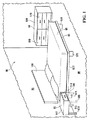
図1を参照すると、例示的な部屋は、床86と、壁88と、全体的に90で示され、ナイトテーブル(nightstand)92、化粧台94、ベッド96、マットレス98、およびヘッドボードシステム100を含む例示的な家具システムとを含む。
With reference to FIG. 1, an exemplary room is indicated by a
図2を参照すると、ヘッドボードシステム100は、装飾カバー102と、詰め物104と、本体106と、壁取り付け型補強用板材108とを含む。図示の実施形態における装飾カバー102は、外面112を有する概矩形部110を含む。外面112は、たとえば、装飾的な色、装飾品、または模様を含むことができる。装飾カバー102はまた、概矩形部110の外周から全体的に延在し、概矩形部110に概ね直交する外側部114、116、118および120を含む。概矩形部110および外側部114、116、118および120は、たとえば、任意の普通に入手できる布で作製され、共に縫い合わされる。
Referring to FIG. 2, the
図3を参照すると、外側部114、116、118および120は、概矩形部110に面するそれぞれの内面122、124、126および128を有する。
Referring to FIG. 3, the
外側部114、116、118および120はまた、それぞれの外縁130、132、134および136を有する。装飾カバー102はまた、外縁130、132、134および136に近接した内面122、124、126および128上にコネクタ138を有する。図示の実施形態では、コネクタ138は、たとえば一般にVELCRO(商標)として知られるフックアンドループコネクタなど、フックアンドループコネクタのいわゆる「ループ側」である。
The
再び図2を参照すると、図示の実施形態における詰め物104は、多くの普通に入手できる発泡材料のうちの1つまたは複数で作製された概ね矩形の本体を含む。別の実施形態では、詰め物104は、たとえば、気泡(air bladder)または羽毛の詰め物を含むことができる。したがって、いくつかの実施形態における詰め物104は、たとえば、望ましくないアレルゲンを避けるために選択される。詰め物104は、法律によって必要とされることがある難燃性物質を含むことができる。さらに、詰め物104は、全体的に図3の140で示される陥凹内で受けられるような大きさに作られ、装飾カバー102の概矩形部110と外側部114、116、118および120とによって画定される。
Referring again to FIG. 2, the
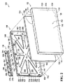
図2、図4、および図5を参照すると、本体106は、全体的に142で示され、外周146を有する前面144を有する、前側面を有する。本体106はまた、全体的に148で示され、前側面142に対向し、背面150を有する後側面を有する。本体106はまた、前面144と背面150との間に外向きの外側面152を有する。さらに、コネクタ154は、本体106上にあり、前面144の外周146の少なくとも一部分に連続的に隣接している。図示の実施形態では、コネクタ154は、たとえば一般にVELCRO(商標)として知られるフックアンドループコネクタなど、フックアンドループコネクタのいわゆる「フック側」である。
With reference to FIGS. 2, 4, and 5, the
したがって、本体106上の(「第1のコネクタ」またはより一般的には「ホルダ」と呼ばれることがある)コネクタ154は、装飾カバー102上の(「第2のコネクタ」と呼ばれることがある)コネクタ138に、着脱式に接続可能である。図示の実施形態では、装飾カバー102上のコネクタ138および本体106上のコネクタ154は、それぞれ、フックアンドループコネクタのいわゆる「ループ側」および「フック側」であり、したがって、本体106上のコネクタ154は、装飾カバー102上のコネクタ138を補完する。
Accordingly, a
代替的な実施形態では、たとえば、装飾カバー102がフックアンドループコネクタの「フック側」を含み、本体106がフックアンドループコネクタの「ループ側」を含んでよい。また、コネクタ154は、図示の実施形態では本体106の外側面152上にあるが、代替的な実施形態では、たとえばコネクタ154は、前面144上または背面150上にあってもよい。したがって、この情況における「外周146に隣接する」は、コネクタ154が外周146に隣接するかまたは正確に外周146上にある必要はなく、むしろ、「外周146に隣接する」は、コネクタ154が外周146に十分に接近しており、コネクタ154がコネクタ138に接続されると、装飾カバー102が、外周146で囲まれる前面144の少なくとも一部分を覆うように見え、それによりヘッドボードシステム100がヘッドボードとして、またはより一般的に装飾パネルとして概ね機能する、実施形態を含む。
In an alternative embodiment, for example, the
さらに、図示の実施形態では、コネクタ154は、前面144の外周146全体に隣接して延在している。しかしながら、代替的な実施形態では、コネクタ154は、実質的に前面144の外周146全体に隣接して延在してよく、またはコネクタ154は、前面144の外周146の少なくとも大部分に隣接して延在してもよい。コネクタ154が、外周146の十分な部分に隣接して延在し、それによりコネクタ154は装飾カバー102上のコネクタ138と接続可能であり、それゆえ装飾カバー102が本体106上に連続的に接続されているように見える場合、コネクタ154は、前面144の外周146全体に「実質的に」隣接して延在しているものと見なされてよい。
Further, in the illustrated embodiment, the
さらに図2および図4を参照すると、本体106は、外側面152と内向面158とを有する凸部156を画定する。図示の実施形態では、本体106の前面144は、凸部156の内向面158と概ね平らな平面部160とを含む。さらに、内向面158は、概ね平らな平面部160と本体106の外側面152との間にある。内向面158および概ね平らな平面部160は、本体106と装飾カバー102との間で詰め物104を受けるために、全体的に162で示される陥凹を画定する。
Still referring to FIGS. 2 and 4, the
図2、図4および図5を参照すると、本体106は、前面144の概ね平らな平面部160内において全体的に164、166、168、170、172、174、176、178および180で示され、前面144と背面150との間に延在する、貫通孔を画定する。図5に示すように、後側面148上で、本体106は、貫通孔164、166、168、170、172、174、176、178および180に近接してそれぞれの補強用板材を画定する。たとえば、図6を参照すると、本体106は、後側面148上で貫通孔172に近接して補強用板材182を画定する。補強用板材182は、全体的に184で示される比較的広い部分と、比較的広い部分184と背面150との間で、全体的に186で示される比較的狭い部分とを含む。したがって、補強用板材182は、貫通孔172を貫通するねじまたはストリングを、比較的狭い部分186の周辺で結合し、比較的広い部分184によって所定の位置に保持することを可能にする。
With reference to FIGS. 2, 4, and 5, the
図2、図5および図6を参照すると、詰め物104は、本体106の陥凹162内で、また装飾カバー102の陥凹140(図3にも示す)内で受けることができる。たとえば、ニードル(図示せず)を使用して、ねじまたはストリングは、貫通孔164、166、168、170、172、174、176、178および180のうちの1つまたは複数を通り、詰め物104および装飾カバー102を通り、ボタン(図示せず)を通って進み、反対に装飾カバー102と、詰め物104と、本体106の貫通孔とを通って進むことができる。次いで、ねじまたはストリングは、たとえば図6に示す補強用板材182など、それぞれの補強用板材に締結される。したがって、貫通孔およびそれぞれの補強用板材は、それぞれのボタン(図示せず)を装飾カバー102および詰め物104に対して引張り、詰め物104の、ボタンに近接する領域を圧縮して、装飾カバー102の外面112に凹凸のある外観(textured appearance)を与えることを可能にする。その例では、ボタンと、ねじまたはストリングとは、貫通孔を通り、詰め物104を通り、装飾カバー102を通って受けられる締結具として機能して、それぞれの締結具を囲むそれぞれの領域内で詰め物104を圧縮する。
With reference to FIGS. 2, 5, and 6, the
図2、図4および図5を参照すると、本体106は、前面144と背面150との間に延在する追加の貫通孔188、190、192、194、196、198および200を画定する。いくつかの実施形態では、そのような追加の貫通孔は、本体106の重量と製造コストとを低減することができる。代替的な実施形態では、貫通孔188、190、192、194、196、198および200は省略されてよく、または異なる形状を有してよく、または代わりに熱可塑性材料(図示せず)の薄膜で閉じられてもよい。いくつかの実施形態では、熱可塑性材料の薄膜は、詰め物が貫通孔188、190、192、194、196、198および200を通り抜けることを防止することによって、または詰め物を損傷する恐れがある物体が貫通孔188、190、192、194、196、198および200を通り抜けることを防止することによって、(たとえば、図2に示す詰め物104などの)詰め物を保護することができる。
With reference to FIGS. 2, 4, and 5, the
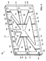
図5を参照すると、後側面148上で、図示の実施形態における本体106はまた、本体106に付加的な強度を与えるために、例示的な構想的リブ202および204など、複数の構想的リブを画定する。
Referring to FIG. 5, on the
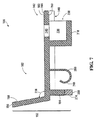
図7を参照すると、図示の実施形態では、凸部156が、本体106の概ね平らな平面部160から斜角206に延在し、本体106はまた、後側面148上に、概ね平らな平面部160から概ね垂直に延在する凸部208を画定する。図示の実施形態では、コネクタ154が凸部208上にあり、外側面152が凸部156と208上にある。しかしながら、代替的な実施形態では、コネクタ154は、凸部156上にあってもよく、または上記のように前面144上もしくは背面150上にあってもよい。
Referring to FIG. 7, in the illustrated embodiment, a
図8を参照すると、本体106は、本体106の前側面142上で隣接する同様の本体210に対して、および本体106の後側面148上で隣接する同様の本体212に対して、積み重ね可能である。図示の実施形態では、隣接する同様の本体210は、本体106の外側面152と実質的に同じである外側面214を有し、隣接する同様の本体210が本体106の陥凹162内で受けられ、前側面142に対して積み重ねられると、隣接する同様の本体210の外側面214の一部分が本体106の内向面158の一部分と接触するように、外側面152と214とが配置される。さらに、隣接する同様の本体212は、本体106の内向面158と実質的に同じである内向面216を有し、隣接する同様の本体212が本体106の後側面148に対して積み重ねられると、本体106の外側面152の少なくとも一部分が、隣接する同様の本体212の内向面216の少なくとも一部分と接触する。
Referring to FIG. 8, the
再び図5を参照すると、本体106は、後側面148上に追加の凸部218、220、222、224、226、228、230、232および234を画定する。再び図7を参照すると、凸部218は、キャビティ236と、本体106の後側面148の238で全体的に示され、キャビティ236と連通する開口と、を画定する。本体106はまた、本体106の前面144とキャビティ236との間に延在する開口240を画定する。再び図5を参照すると、凸部220、222、224、226、228、230、232および234は、凸部218と実質的に同じであり、全体的に242、244、246、248、250、252、254および256で示され、開口238と実質的に同じであるそれぞれの開口を画定する。一般に、開口238、242、244、246、248、250、252、254および256は、それぞれの凸部内のそれぞれのキャビティから内側を向く。
Referring again to FIG. 5, the
再び図8を参照すると、隣接する同様の本体210および212は、凸部218と実質的に同じであるそれぞれの凸部258および260を有する。隣接する同様の本体210が本体106の前側面142に対して積み重ねられると、隣接する同様の本体210の凸部258が本体106の前面144に接触し、隣接する同様の本体212が本体106の後側面148に対して積み重ねられると、凸部218が本体106の前面144と実質的に同じである隣接する同様の本体212の前面262に接触する。図5および図8を参照すると、いくつかの実施形態における凸部218、220、222、224、226、228、230、232、234、258および260は、したがって、たとえば図8に示す積み重ねられた本体106、210および212などの積み重ねられた本体間の接触を増加させ、そのような実施形態は、したがって、たとえば図8に示す積み重ねられたシステムなど、本体の積み重ねられたシステムにおいて、付加的な安定性を有することができる。
Referring again to FIG. 8, adjacent
再び図5を参照すると、後側面148上で、本体106はまた、凸部208に近接する例示的なクリップ264および266など、複数のクリップを有する。再び図7を参照すると、クリップ266は、たとえば、発光ダイオード(「LED」)のライトストリングなどの光源(図示せず)を着脱可能に受けるための変形可能なカール部268を含む。したがって、再び図5を参照すると、凸部208に近接して示される複数のクリップは、そのようなライトストリングを、実質的に本体106の背面150の外周の周りで、本体106に接続する光源コネクタとして機能する。光源のための代替のコネクタには、たとえばテープが含まれてよい。
Referring again to FIG. 5, on the
さらに図5を参照すると、電気スイッチ270および272が、外側面152を通して本体106の凸部208上に配置される。図9を参照すると、電気スイッチ270が示されており、電気スイッチ272は実質的に同じものである。図示の実施形態における電気スイッチ270および272は三路スイッチであり、したがって、両スイッチは、電気スイッチ270または272のいずれかが光源をオンまたはオフにすることができるように、光源(図示せず)に接続される。本体106はまた、たとえば、LEDのライトストリングに適切な電圧を供給するために、電圧変換器(図示せず)を有することができる。
Still referring to FIG. 5,
再び図7を参照すると、図示の実施形態における凸部208は、クリップ264および266などのクリップで保持された光源(図示せず)からの光を伝導する透光部274を含む。代替的実施形態は、着脱式の透光カバーを含むことができ、または代替として、透光部274が省略されてよく、透光部274の代わりに本体106内にギャップが残され、ギャップを通して光が進むことができる。図示の実施形態では、透光部274が唯一の透光部であるが、代替実施形態では、他の部分または実質的に本体106のすべてが透光性であってもよく、その実施形態では、本体106は、単一の種類の熱可塑性材料で形成されてよい。
Referring again to FIG. 7, the
再び図2を参照すると、補強用板材108を(図1に示す壁88などの)壁に装着する締結具(図示せず)を受けるために、補強用板材108は、例示的な貫通孔276および278など、複数の貫通孔を画定する。図示の実施形態では、そのような貫通孔は、締結具(図示せず)を壁内のスタッド(図示せず)に取り付けることを可能にし、かつ補強用板材108をそのような締結具に対して滑動することを可能にするために細長であり、そのことが、いくつかの実施形態では、そのようなスタッドの位置によって過度に制限されることのない位置で、補強用板材108を壁に装着することを可能にする。補強用板材108はまた、それぞれの上縁286、288および290を有する凸部280、282および284を含む。図示の実施形態では、凸部280、282および284は、共通の間隔で離間しており、再び図5を参照すると、開口238、242および244、開口246、248および250、ならびに開口252、254および256は、同じ間隔で離間している。したがって、一実施形態では、開口238、242および244は、補強用板材108が装着される壁(図1に示す壁88など)に本体106を装着するために、凸部284、282および280をそれぞれ受けることができる。たとえば、図10は、開口244および242内にそれぞれ受けられた凸部280および282を示す。
Referring again to FIG. 2, to receive a fastener (not shown) that attaches the reinforcing
いくつかの実施形態では、凸部280、282および284などの凸部は、凸部222、220および218などの凸部の内面と協働するラッチとして機能することができ、それにより、凸部280、282および284は、それぞれ、凸部222、220および218内で解除可能に保持され、またそれにより、凸部280、282および284は、本体106を補強用板材108から解除するために、一時的に変形される。図示の実施形態では、凸部280、282および284は、本体106の前側面142からアクセス可能であり、したがって、本体106を補強用板材108から解除する解除スイッチとして機能し、いくつかの実施形態は、本体106を補強用板材108上に保持し、それにより、装飾カバー102および詰め物104が取り外されているときだけ、本体106が補強用板材108から解除される。そのような実施形態におけるそのような解除可能な接続は、さらに、本体106、詰め物104および装飾カバー102を(図1に示す壁88などの)壁に固定することができる。
In some embodiments, protrusions such as
図2および図5を参照すると、凸部218、220および222のそれぞれの離間した縁部は、したがって、本体106を(図1に示す壁88などの)壁に装着する、本体106上のコネクタとして機能する。さらに、凸部280、282および284の複数の離間した上縁286、288および290は、したがって、本体106上のそのようなコネクタを補完するコネクタとして、それぞれ機能する。
Referring to FIGS. 2 and 5, the spaced edges of each of the
さらに図2および図5を参照すると、補強用板材108の凸部280、282および284は、代替的に、それぞれ凸部224、226および228の、それぞれの開口246、248および250の中で受けられる。凸部224、226および228は、それぞれ凸部280、282および284の、それぞれの上縁286、288および290を補完する縁部を含み、凸部224、226および228内の縁部は、凸部218、220および222内の実質的に同様の縁部に対して概ね垂直であり、より一般的には非平行である。したがって、本体106は、図10に示す方式に対して垂直な方式で掛けられる。さらに、補強用板材108の凸部284、282および280はまた、それぞれ凸部230、232および234の、それぞれ開口252、254および256内で受けられてよく、やはり、本体106を、図10に示す方式に対して垂直に装着する。したがって、凸部224、226および228の複数のそれぞれの離間した縁部はまた、本体106を(図1に示す壁88などの)壁に装着する別のコネクタとして機能し、凸部230、232および234の複数のそれぞれの離間した縁部もまた、装置本体106を壁に装着するコネクタとして機能する。
2 and 5, the
再び図5を参照すると、図示の実施形態における本体106は、後側面148において、物を格納する格納コンパートメント292を画定する。たとえば、ヘッドボードシステム100(図2に示す)内に、小さいが貴重な物を人目に触れずに格納することが望ましい。いくつかの実施形態では、格納コンパートメント292は、たとえば上述のように、装飾カバー102の外面112に凹凸のある外観を与えるために、1つまたは複数のボタン、針および糸を保持することができる。図示の実施形態では、格納コンパートメント292は、格納コンパートメント292のトップサイド上の、全体的に294で示される開口において開いている。しかしながら、代替的な実施形態では、格納コンパートメント292は、たとえば、取外し可能なカバーを含むことができる。
Referring again to FIG. 5, the
再び図2を参照すると、図示の実施形態では、本体106は、前側面142上に傾き測定デバイス296を有する。補強用板材108もまた、傾き測定デバイス298を含む。図示の実施形態における傾き測定デバイス296および298は、着脱可能な気泡水準器であり、いくつかの実施形態では、傾き測定デバイス296および298は、重力に対する本体106および補強用板材108それぞれの傾きを示すことができる。いくつかの実施形態では、そのような傾きの情報は、たとえば、補強用板材108および本体106を室内で水平に位置決めするのを助けることができる。
Referring again to FIG. 2, in the illustrated embodiment, the
図11を参照すると、詰め物104が、本体106の陥凹162の中と装飾カバー102の陥凹140の中とで受けられるように組み立てられたヘッドボードシステム100が、示されている。外側部114、116、118および120が、本体106の外側面152上に配置され、装飾カバー102上のコネクタ138が、本体106上のコネクタ154と着脱可能に接続され、たとえば、外面112が、部屋を装飾するために露出されたままとなる。したがって、図示の実施形態では、本体106は、装飾カバー102を保持する装置として機能し、したがって、いくつかの実施形態では、ベッドのためのヘッドボードとして機能することができる。
Referring to FIG. 11, the
図示の実施形態では、フックアンドループコネクタ138および154は、装飾カバー102を本体106にアップホルスターすることに伴う時間と費用とを避けることができる。たとえば、新しい色彩設計を反映するために外面112を更新するために、装飾カバー102を交換することが望ましい場合、装飾カバー102は、フックアンドループコネクタ138および154を取り外し、新しい装飾カバー102のコネクタ138を本体106のコネクタ154に再び取り付けることによって、簡単に取り替えられる。
In the illustrated embodiment, the hook and
図示の実施形態では、本体106および補強用板材108は実質的に熱可塑性であり、たとえば、高密度ポリエチレンまたはポリプロピレンで形成されるが、たとえば炭素樹脂など、他の熱可塑性材料が、代替として使用される。本体106および補強用板材108は、たとえば、電気スイッチ270および272ならびに傾き測定デバイス296および298など、熱可塑性でない材料を含むことがあるが、依然として、「実質的に」熱可塑性である。一般に、「実質的に」熱可塑性の本体は、大量のそのような本体を比較的安価に生産することを可能にする鋳型内で形成される、主要な構造的要素を含むことができるが、そのような「実質的に」熱可塑性の本体はまた、たとえば、電気スイッチ270および272の要素ならびに傾き測定デバイス296および298の要素など、熱可塑性でない要素を含むことができる。本体106および補強用板材108は、たとえば、ニューメキシコ州アルバカーキのBio-Tec Environmental, LLC社から市販されているECOPURE(商標)として既知の添加剤など、添加剤を含むことがある、任意の一般的に入手可能な熱可塑性材料で作製される。代替実施形態は、いくつかの実施形態において熱可塑性でない他の材料を含むことができる。
In the illustrated embodiment, the
たとえば、ヘッドボードシステム100にトコジラミがまん延するようになった場合、装飾カバー102および詰め物104が本体106から取り外され、廃棄されるかまたは清浄化されて元の位置に戻される。たとえば、トコジラミを殺すために、装飾カバー102は洗濯されてよく、詰め物104は、十分な期間の間、単に倉庫に放置されてよいが、他にもいくつかの可能性が存在する。さらに、本体106は実質的に熱可塑性であり、それゆえ容易に清浄化され、新しいかまたは清浄化された装飾カバー102および新しいかまたは清浄化された詰め物104が、清浄化された本体106上に設置され、そのことで、いくつかの実施形態では、ヘッドボード全体を取り換えることによる浪費、出費および環境破壊が回避される。そのように低減された浪費および出費は、たとえば、トコジラミのまん延への対応が非常にコスト高となることがあるホテルなど、大型施設において特に有利である。さらに、たとえば、装飾カバー102の外観を変えること、または詰め物104を変えることが望ましい場合、必要なそれらの構成要素だけが取り替えられ、そのことで、たとえば、ホテルの1つもしくは複数の部屋またはホテル全体において装飾物または詰め物の材料を交換するためのコストが低減される。
For example, if bedbugs spread around the
いくつかの実施形態では、実質的に熱可塑性の本体106は、消毒あるいは清浄化され、装飾カバー102および詰め物104は取り外され、清浄化され、かつ取り替えられるが、一方、たとえばアップホルスターされたヘッドボードにおける類似の構成要素は、一般に再使用されず、ひとたび取り外されると廃棄されなければならないので、より一般的には、ヘッドボードシステム100は、たとえばアップホルスターされたヘッドボードなど、既知のヘッドボードより衛生的である。したがって、ヘッドボード内で装飾カバーを保持するために任意のホルダを有する実質的に熱可塑性の本体のいくつかの実施形態は、多くの既知のヘッドボードより有利である。
In some embodiments, the substantially
さらに、本体106と補強用板材108の一方または両方が、それらの中に組み込まれた珪藻土を含むことができる。一実施形態では、熱可塑性材料が、鋳型に注入される前で、液相にあるとき、珪藻土を本体106の熱可塑性材料に付加することによって、珪藻土が本体106の中に組み込まれる。一実施形態では、本体106の約30重量%が珪藻土である。さらに、追加の珪藻土が、本体106の外向きの外側面152または他の表面に付着されてよい。いくつかの実験では、珪藻土をそのようにして含む本体は、そのような本体の近くにいるトコジラミを効果的に殺すことが発見されている。そのような一実験では、そのような本体は、本体が製造された後の少なくとも1年の間、トコジラミを殺すことを継続した。したがって、そのような材料は、トコジラミのまん延をさらに防止または低減することができるが、そのことは、たとえばホテルなどの大型施設においては、非常にコストがかかることがある。
Furthermore, one or both of the
いくつかの実施形態では、珪藻土は、CELATOM(商標)MN−51を含むことがあり、CELATOM(商標)MN−51は、米国ネバダ州レノ、Suite 1000、Gateway Drive 9785のEP Minerals, LLC社から市販されており、たとえば、約900°F(約480℃)または他の温度で熱処理または気流乾燥される。一実施形態では、珪藻土を気流乾燥することは、珪藻土を約900°F(約480℃)で約15秒間加熱することを伴う。そのような熱処理または気流乾燥は、珪藻土の特性を、より角立ったものに、したがって動物の外骨格またはより具体的にはトコジラミの外骨格により損傷を与えるように変えることができ、そのような熱処理または気流乾燥はまた、珪藻土を完全に乾燥させ、それにより珪藻土をより吸収性にして、トコジラミなどの動物を脱水させて殺すことができ、本明細で説明する様々な実施形態を含む様々な実施形態において潜在的により効果的であるものと考えられる。 In some embodiments, the diatomaceous earth may comprise CELATOM ™ MN-51, which is from EP Minerals, LLC of Suite 1000, Gateway Drive 9785, Reno, Nevada, USA. Commercially available, for example, heat treated or air dried at about 900 ° F. (about 480 ° C.) or other temperatures. In one embodiment, air drying the diatomaceous earth involves heating the diatomaceous earth at about 900 ° F. (about 480 ° C.) for about 15 seconds. Such heat treatment or air-drying can change the properties of diatomaceous earth to be more acute and thus damaged by the exoskeleton of animals or more specifically by the exoskeleton of bed bugs, such as Heat treatment or airflow drying can also completely dry the diatomaceous earth, thereby making the diatomaceous earth more absorbable and dehydrating and killing animals such as bed bugs, including various embodiments described herein. It is considered potentially more effective in embodiments.
CELATOM(商標)MN−51として既知の珪藻土は、いくつかの実施形態において特に効果的であることがあり、そのような珪藻土は、以下の特性を有するものと考えられる。 Diatomaceous earth known as CELATOM ™ MN-51 may be particularly effective in some embodiments, and such diatomaceous earth is believed to have the following properties.

代替実施形態では、珪藻土は、CELATOM(商標)MN−53として既知の珪藻土を含んでよく、CELATOM(商標)MN−53もまた、米国ネバダ州レノ、Suite 1000、Gateway Drive 9785のEP Minerals, LLC社から市販されている。CELATOM(商標)MN−53として既知の珪藻土は、以下の特性を有しているものと考えられる。 In an alternative embodiment, the diatomaceous earth may comprise diatomaceous earth known as CELATOM ™ MN-53, which is also known as EP Minerals, LLC of Suite 1000, Gateway Drive 9785, Reno, Nevada, USA. It is commercially available from the company. Diatomaceous earth known as CELATOM ™ MN-53 is considered to have the following properties:
2011年6月23日の一実験では、Gelman Sciences(商標)から市販されている、それぞれが直径約5.0センチメートル(「cm」)または約2.0インチの小さなプラスチックのペトリ皿が、生物検定に使用された。直径約1.5cm(または約0.6インチ)の小さな開口を蓋の中に切り、トコジラミが呼吸できるように1片のガーゼで閉じた。ペトリ皿は、直径約4.25cm(または約1.7インチ)のフィルタ紙で内側を覆った(lined)。珪藻土を計重し、鉗子を用いてフィルタ紙上に均一に拡散した。10個の成長した現場収集のトコジラミをペトリ皿のそれぞれに入れ、それらが逃げないように、皿の上に蓋を載せた。箱の中の湿度を保つために水を噴霧した紙タオルで内側を覆ったプラスチックの箱の中に、ペトリ皿を移した。実験は室温で行い、トコジラミをペトリ皿に入れてから24、48、72および96時間後に、死虫数を記録した。各製品の、トコジラミの50%を殺すのに十分な最低致死濃度(「LC50」)を計算するために、約0.5ミリグラム(「mg」)と約2.0ミリグラムとの間の4つの濃度を使用した。それぞれ10個のトコジラミの単一のレプリケーションがあった。 In one experiment on June 23, 2011, small plastic Petri dishes, each about 5.0 centimeters (“cm”) or about 2.0 inches in diameter, commercially available from Gelman Sciences ™, Used for bioassay. A small opening about 1.5 cm (or about 0.6 inches) in diameter was cut into the lid and closed with a piece of gauze so that bedbugs could breathe. The Petri dish was lined with filter paper having a diameter of about 4.25 cm (or about 1.7 inches). Diatomaceous earth was weighed and evenly spread on the filter paper using forceps. Ten grown field-collected bed bugs were placed in each of the Petri dishes and a lid was placed on the dish to prevent them from escaping. The Petri dish was transferred into a plastic box lined with a paper towel sprayed with water to maintain the humidity inside the box. Experiments were performed at room temperature, and the number of dead insects was recorded 24, 48, 72 and 96 hours after placing the bed bugs in petri dishes. 4 between about 0.5 milligrams (“mg”) and about 2.0 milligrams to calculate the lowest lethal concentration (“LC 50 ”) sufficient to kill 50% of bed bugs for each product. Two concentrations were used. There was a single replication of 10 bed bugs each.
以下の表3および表4は、2011年6月23日の実験による死虫数のデータを示しており、ここで、Lは、表中の対応する所与の時間後にまだ生きているトコジラミの数を指し、Dは、所与の時間後に死んだ数を指す。 Tables 3 and 4 below show death count data from the June 23, 2011 experiment, where L is the number of bed bugs still alive after the corresponding given time in the table. Refers to the number, D refers to the number that died after a given time.
すべてのトコジラミが、CELATOM(商標)MN−51の珪藻土の中で、48時間後に死んだ。したがって、CELATOM(商標)MN−51に対するLC50は、48時間に対してのみ計算され、CELATOM(商標)MN−51に対する48時間後のLC50は、0.7mgとして計算された。CELATOM(商標)MN−53に対する48時間後のデータは、計算に有効ではなく、したがって、CELATOM(商標)MN−53に対するLC50は、96時間後に0.8mg(0.552〜1.052)として計算された。 All bed bugs died after 48 hours in CELATOM ™ MN-51 diatomaceous earth. Therefore, the LC 50 for CELATOM ™ MN-51 was calculated only for 48 hours, and the LC 50 after 48 hours for CELATOM ™ MN-51 was calculated as 0.7 mg. The data after 48 hours for CELATOM ™ MN-53 is not valid for the calculation, therefore the LC 50 for CELATOM ™ MN-53 is 0.8 mg (0.552-1.052) after 96 hours. As calculated.
CELATOM(商標)MN−51に対する比較的低いLC50は、CELATOM(商標)MN−51が、CELATOM(商標)MN−53より、トコジラミに対する毒性が強い可能性があり、CELATOM(商標)MN−51は、昆虫を防除するために、またはより具体的にはトコジラミを防除するために特に効果的である可能性があることを示唆する。 The relatively low LC 50 for CELATOM ™ MN-51 may indicate that CELATOM ™ MN-51 is more toxic to bed bugs than CELATOM ™ MN-53, and CELATOM ™ MN-51 Suggests that it may be particularly effective for controlling insects, or more specifically for controlling bed bugs.
2012年2月1日の別の実験では、6個のペトリ皿(それぞれが直径約5.0cmまたは約2.0インチ)に、CELATOM(商標)MN−51を含むエアロゾルを噴霧し、CELATOM(商標)MN−51の薄い被膜を乾燥後に残存させ、そのような6個のペトリ皿を、一実験群として使用した。追加の6個のペトリ皿(それぞれが直径5.0cmまたは約2.0インチ)には、エアロゾルまたは珪藻土を与えず、それらの6個のペトリ皿を、対照群(control group)として使用した。12個のペトリ皿のそれぞれに5個のトコジラミを入れ、トコジラミが逃げないように蓋をした。トコジラミをペトリ皿に入れてから3、15、18および24時間後に、死虫数を評価し、対照群の中に死んだ虫はなかった。実験群における死虫数を、以下の表5に示す。 In another experiment on February 1, 2012, six Petri dishes (each about 5.0 cm in diameter or about 2.0 inches in diameter) were sprayed with an aerosol containing CELATOM ™ MN-51 and CELATOM ( A thin film of MN-51 was left after drying and six such Petri dishes were used as one experimental group. An additional 6 Petri dishes (each 5.0 cm in diameter or about 2.0 inches) were not given aerosol or diatomaceous earth, and these 6 Petri dishes were used as a control group. Five bed bugs were placed in each of the 12 petri dishes, and a lid was placed so that the bed bugs would not escape. The number of dead insects was assessed 3, 15, 18 and 24 hours after placing the bed bugs in the Petri dishes, and no dead insects were found in the control group. The number of dead insects in the experimental group is shown in Table 5 below.
したがって、2012年2月1日の実験では、CELATOM(商標)MN−51を含むエアロゾルに曝されたすべてのトコジラミが24時間以内に死んだが、対照群のトコジラミはいずれも、24時間以内に死ななかった。 Thus, in the February 1, 2012 experiment, all bedbugs exposed to aerosols containing CELATOM ™ MN-51 died within 24 hours, while all control bedbugs died within 24 hours. There wasn't.
2012年2月12日の別の実験では、プラスチックのRUBBERMAID(商標)の透光性の箱(約73.6cm×約45.7cm×約33.7cmまたは約29インチ×約18インチ×約13.3インチ)を含め(involve)、より具体的には、2つのそのような箱を実験用の箱として含め、2つのそのような箱を対照用の箱として含めた。実験用の箱のそれぞれの中央の、約20cm(または約7.9インチ)の幅の部分に、CELATOM(登録商標)MN−51を含むエアロゾルを噴霧し、乾燥させた。1片の現場収集のシート(約50cm×約24cm、または約19.7インチ×約7.9インチ)で、それぞれの箱の1側面上を覆って、刺激剤として使用した。シートは、トコジラミがまん延した家から収集し、卵と、多くの餌を摂ったばかりのトコジラミが付着していたが、トコジラミは、シート片を箱に入れる前にシートから収集した。現場収集のシート片に対向する、箱の側面は、清潔で新しい布の片で覆われた。50個の成長したトコジラミを各箱の中の清潔な布の上に入れ、箱を蓋で閉じた。対照の箱は、実験用の箱に類似するが、エアロゾルを含んでいなかった。 In another experiment on February 12, 2012, a plastic RUBBERMAID ™ translucent box (about 73.6 cm x about 45.7 cm x about 33.7 cm or about 29 inches x about 18 inches x about 13). .3 inches), more specifically, two such boxes were included as experimental boxes, and two such boxes were included as control boxes. An aerosol containing CELATOM® MN-51 was sprayed and dried in the center of each experimental box, about 20 cm (or about 7.9 inches) wide. A piece of field-collected sheet (about 50 cm x about 24 cm, or about 19.7 inches x about 7.9 inches) covered one side of each box and used as a stimulant. The sheets were collected from the house where the bed bugs were spread, and the eggs and the bedbugs that had just received a lot of food were attached, but the bed bugs were collected from the sheets before placing the sheet pieces in the box. The side of the box, facing the piece of sheet collected in the field, was covered with a clean piece of fresh cloth. Fifty grown bed bugs were placed on a clean cloth in each box and the box was closed with a lid. The control box was similar to the experimental box, but contained no aerosol.
4つの箱のすべての中で、トコジラミは、清潔な布を有する箱の側面から、現場収集のシート片を有する箱の側面に移動した。48時間後、対照用の箱の中の死虫数はゼロであったが、24時間後、実験用の箱のうちの1つは、50個のトコジラミのうち43の死虫数を示し、他の実験用の箱は、50個のトコジラミのうち45の死虫数を示した。48時間後に、実験用の箱の中のすべてのトコジラミが死んだ。トコジラミは、仰向けに死んでおり、エアロゾルの生成物のダストが着いていた。したがって、CELATOM(商標)MN−51で処理された領域をトコジラミが横断するときの短い曝露でさえ、トコジラミに高い死虫率をもたらすのに十分であるものと考えられる。 In all four boxes, bedbugs moved from the side of the box with a clean cloth to the side of the box with a piece of sheet collected in the field. After 48 hours, the number of dead insects in the control box was zero, but after 24 hours, one of the experimental boxes showed 43 dead insects out of 50 bed bugs, Other experimental boxes showed 45 dead insects out of 50 bed bugs. After 48 hours, all bed bugs in the experimental box died. Bed bugs were dead on their back and were dusted with aerosol products. Thus, even short exposures when bedbugs traverse an area treated with CELATOM ™ MN-51 are considered to be sufficient to provide high mortality to bedbugs.
1個のトコジラミが珪藻土に接触すると、そのトコジラミが、他のトコジラミに珪藻土を拡散し、したがって、1個のトコジラミを珪藻土に接触させることで、数個のトコジラミを殺すことができるものと考えられる。たとえば、一実験では、1個のトコジラミに珪藻土と蛍光染料とに直接触れさせ、そのトコジラミを、珪藻土に直接触れさせていなかった他の数個のトコジラミに接触させた。珪藻土に直接触れさせていなかったトコジラミの多くが、珪藻土に直接触れていたトコジラミに接触した後、すぐに死んだことが判明した。また、珪藻土に直接触れていたトコジラミに接触した後すぐに死んだトコジラミ上で、蛍光染料が観測され、そのようなトコジラミは、珪藻土に直接触れたトコジラミに接触したことによって珪藻土に接触したことを示唆している。したがって、1個のトコジラミを珪藻土に直接触れさせることによって、多くの場合、数個のトコジラミを殺すことができるものと考えられる。 When a bed bug comes into contact with diatomaceous earth, the bed bug spreads to other bed bugs, and it is thought that several bed bugs can be killed by bringing a bed bug into contact with diatomaceous earth. . For example, in one experiment, one bed bug was brought into direct contact with diatomaceous earth and a fluorescent dye, and the bed bug was brought into contact with several other bed bugs that were not in direct contact with diatomaceous earth. Many of the bed bugs that were not in direct contact with diatomaceous earth were found to have died immediately after contact with bed bugs that had been in direct contact with diatomaceous earth. Fluorescent dyes were also observed on bed bugs that died immediately after contact with bed bugs that had been in direct contact with diatomaceous earth. Suggests. Therefore, in many cases, it is thought that several bed bugs can be killed by making one bed bug directly touch diatomaceous earth.
2012年2月18日の別の実験では、CELATOM(商標)MN−51の死虫率を、2つの市販されている殺虫剤、すなわちALPINE DUST(商標)およびMOTHER EARTH(商標)として既知の殺虫剤と比較した。様々な製品を小さなフィルタ紙上で計重し、次いで、そのフィルタ紙をペトリ皿(直径約5.0cmまたは約2インチ)の中に置いた。トコジラミを様々なペトリ皿の中に入れ、24時間後および48時間後にペトリ皿のそれぞれの中で、死虫率を評価した。各製品に対して4つの濃度を使用し、濃度は0.25mg〜4mgにわたり、各レプリケーションにおいて9個と11個との間のトコジラミの3つのレプリケーションがあった。以下の表6に示すように、LC50およびLC95(トコジラミの95%を殺すのに十分な最低の致死濃度)の値、ならびにLC50およびLC95の値に対する信頼区間(「CI」)を計算するために、プロビット分析を使用した。 In another experiment on February 18, 2012, the mortality of CELATOM ™ MN-51 was determined as two commercially available insecticides, known as ALPINE DUST ™ and MOTHER EARTH ™. Compared to the agent. The various products were weighed on a small filter paper and then the filter paper was placed in a Petri dish (about 5.0 cm in diameter or about 2 inches in diameter). Bed bugs were placed in various petri dishes and mortality was assessed in each of the petri dishes after 24 and 48 hours. Four concentrations were used for each product, with concentrations ranging from 0.25 mg to 4 mg, with 3 replications of between 9 and 11 bed bugs in each replication. As shown in Table 6 below, the values of LC 50 and LC 95 (the lowest lethal concentration sufficient to kill 95% of bed bugs), and the confidence interval (“CI”) for the LC 50 and LC 95 values, Probit analysis was used to calculate.
表6におけるデータは、その実験において、CELATOM(商標)MN−51はALPINE DUST(商標)およびMOTHER EARTH(商標)より低い濃度(具体的には、それらの値に対して、より低いLC50およびLC95ならびにより低いCI)を必要とすることを示しており、したがって、トコジラミの個体数を抑制することにおいて、CELATOM(商標)MN−51は、一般に、ALPINE DUST(商標)およびMOTHER EARTH(商標)より効果的であるものと考えられる。 The data in Table 6 shows that in that experiment, CELATOM ™ MN-51 has a lower concentration of LC50 than ALLPINE DUST ™ and MOTHER EARTH ™ (specifically, lower LC 50 and indicates that require low CI) than well LC 95, therefore, in suppressing populations bedbugs, Celatom (R) MN-51 is generally, ALPINE DUST (TM) and MOTHER EARTH (TM ) It is considered to be more effective.
一般に、珪藻土は、外骨格を有する動物の外骨格を損傷し、その損傷が、動物の脱水および死をもたらすものと考えられる。したがって、珪藻土、ならびに本明細で説明した珪藻土を含むような、様々な装置、キットおよびシステムは、外骨格を有する動物、節足動物、クモ類、昆虫およびトコジラミのうちの1つまたは複数の個体数の抑制において効果的であるものと考えられる。本明細書では、動物の個体数の「抑制」は、個体数を発見する前にそのような個体数の成長または生存を防止することと、同様に個体数を発見した後、そのような個体数の1つまたは複数の構成要素を殺すこととを含んでよい。珪藻土はまた、自然の生成物であり、自然の生成物は、人間に対してまたはより一般的に環境に対して害はより少ないので、概して、自然の生成物は、他の害虫防除製品より好ましい。珪藻土によって殺すことが望ましい動物には、同様に、ゴキブリ、蟻、蚤および他の害虫が含まれる。 In general, diatomaceous earth damages the exoskeleton of animals with exoskeletons, which damage is thought to result in animal dehydration and death. Accordingly, various devices, kits and systems, including diatomaceous earth, and the diatomaceous earth described herein, can include one or more individuals of exoskeleton animals, arthropods, arachnids, insects and bed bugs. It is considered effective in suppressing the number. As used herein, “inhibition” of an animal's population includes preventing the growth or survival of such an individual before discovering the population, as well as, after discovering such an individual, Killing one or more components of the number. Diatomaceous earth is also a natural product, and natural products are generally less harmful to humans or more generally to the environment, so in general natural products are better than other pest control products. preferable. Animals that are desired to be killed by diatomaceous earth include cockroaches, ants, moths and other pests as well.
CELATOM(商標)MN−51およびCELATOM(商標)MN−53ならびに他の製品について、上記で説明したが、いくつかの実施形態は、他のサプライヤによって供給される他のタイプの珪藻土を含むことができる。一般に、いくつかの実施形態におけるそのような珪藻土は、たとえば、約480℃で約15秒間気流乾燥された珪藻土など、熱処理もしくは気流乾燥された珪藻土であってよく、またはより一般的には、改質珪藻土であってもよい。より一般的には、そのような珪藻土は、上記で説明したCELATOM(商標)MN−51またはCELATOM(商標)MN−53の効果と類似の効果を達成するために、上記の表1および表2に列挙されるCELATOM(商標)MN−51またはCELATOM(商標)MN−53の特性のうちの1つまたは複数に類似する、1つまたは複数の特性を有することができる。 Although CELATOM ™ MN-51 and CELATOM ™ MN-53 and other products have been described above, some embodiments may include other types of diatomaceous earth supplied by other suppliers. it can. In general, such diatomaceous earth in some embodiments may be diatomaceous earth that has been heat-treated or air-dried, such as, for example, air-dried at about 480 ° C. for about 15 seconds, or, more generally, modified Kieselguhr may be used. More generally, such diatomaceous earth is used to achieve an effect similar to that of CELATOM ™ MN-51 or CELATOM ™ MN-53 described above in order to achieve Tables 1 and 2 above. Can have one or more properties similar to one or more of the properties of CELATOM ™ MN-51 or CELATOM ™ MN-53 listed in.
さらに、他の実施形態は、トコジラミの個体数を抑制するのに有効である、珪藻土以外の製品、またはより一般的には殺虫剤もしくは農薬を含むことができる。たとえば、特許文献3は、PA1b関連ペプチド、テルペノイドサポニン、トリテルペノイドサポニン、ソヤサポニンI、ソヤサポニンII、ソヤサポニンIII、ソヤサポニンVI、デヒドロソヤサポニンI、エキノシスチン酸3−グルコシド、グリチルリチン酸、ヘデラコシドC、ベータエスシン、アルファフェデリン、および他の、殺虫成分を沈殿させた酢酸のうちの1つまたは複数など、様々なマメ科植物の抽出物を記載している。様々な実施形態では、たとえば、熱可塑性材料が液相にあるときでかつ熱可塑性材料が鋳型に注入される前に、珪藻土、マメ科植物の抽出物、または両方を本体の熱可塑性材料に付加することによって、珪藻土およびそのようなマメ科植物の抽出物の一方または両方が、熱可塑性の本体の中に組み込まれる。 In addition, other embodiments can include products other than diatomaceous earth, or more generally pesticides or pesticides, that are effective in reducing bedbug populations. For example, Patent Document 3 discloses a PA1b related peptide, terpenoid saponin, triterpenoid saponin, soyasaponin I, soyasaponin II, soyasaponin III, soyasaponin VI, dehydrosoyasaponin I, echinocystic acid 3-glucoside, glycyrrhizic acid, hederacoside C, beta escin Describes various legume extracts, such as one or more of alpha federin and other acetic acid precipitated with insecticidal components. In various embodiments, for example, diatomaceous earth, legume extract, or both are added to the body thermoplastic material when the thermoplastic material is in the liquid phase and before the thermoplastic material is injected into the mold. By doing so, one or both of diatomaceous earth and such legume extracts are incorporated into the thermoplastic body.
さらに図11を参照すると、装飾カバー102および本体106は、フックアンドループコネクタ138および154を、装飾カバー102上および本体106上のそれぞれの所定の位置に有するように製造され、そのような所定の位置は、装飾カバー102の所望の位置および張力を詰め物104上に与えるように決定される。したがって、装飾カバー102は、コネクタ138をコネクタ154に調整することによって簡単にそのような所望の位置および張力に取り付けることができる。したがって、図示の実施形態では、本体106上の装飾カバー102の所望の位置は、相補的なコネクタ138および154のそれぞれの位置によってあらかじめ定めることができるので、装飾カバー102上のコネクタ138を補完する本体106上のコネクタ154は、装飾カバー102を本体106上に保持することを簡素化し、そのことで、装飾カバーをフレームに接続する間に装飾カバーを注意深くフレーム上で位置決めする必要をなくすことができる。さらに、いくつかの実施形態では、装飾カバー102を本体106上に取り付けるときに、装飾カバー102を引っ張るかまたは変形させる必要はない。
Still referring to FIG. 11, the
またさらに、図示の実施形態では、コネクタ138および154は連続的なフックアンドループコネクタであるので、装飾カバーをフレーム上に離散的な点だけで接続することに起因することがある、見苦しい外観を避けることができる。
Still further, in the illustrated embodiment, the
図12を参照すると、別の例示的な本体が全体的に300で示され、全体的に302で示される前側面を有し、前面304を有する。前面304は、概ね平らな平面部306と内向部308とを含む。本体300はまた、全体的に310で示され、前側面302に対向する後側面と、外向きの外側面312とを有する。したがって、前面304の内向部308は、概ね平らな平面部306と本体300の外側面312との間にある。本体300は、上記で説明した本体106と実質的に同様であり、装飾カバーを保持する装置と同様に機能し、本体106と同様の材料を含むが、内向部308は、概ね平らな平面部306に隣接して概ね垂直に延在する第1の部分314と、第1の部分314に隣接して第1の部分314に非平行に、概ね平らな平面部306から離れて延在する第2の部分316と、第2の部分316に隣接して第1の部分314に概ね平行に、概ね平らな平面部306から離れて延在する第3の部分318とを含む。また、図示の実施形態における外側面312は、内向部308を概ね補完する相補部320を含む。
Referring to FIG. 12, another exemplary body is generally designated 300, has a front side generally designated 302, and has a
したがって、図13を参照すると、本体300は、本体300の前側面302上で隣接する同様の本体322に対して、および本体300の後側面310上で隣接する同様の本体324に対して、積み重ね可能である。したがって、隣接する同様の本体322の外側面312の相補部320は、隣接する同様の本体322が本体300の前側面302に対して積み重ねられると、本体300の内向部308に接触する。さらに、本体300の外側面312の相補部320は、隣接する同様の本体324が本体300の後側面310に対して積み重ねられると、隣接する同様の本体324の内向部308に接触する。
Accordingly, with reference to FIG. 13, the
図14、図15および図16を参照すると、別の例示的な本体が全体的に326で示され、全体的に328で示される前側面と、全体的に330で示される、対向する後側面とを含む。前側面328は外周334を有し、概ね平らな平面部336と内向部338とを含む、前面332を有する。本体326はまた、前面332と、後側面330上の背面342との間に外向きの外側面340を含む。本体326は、たとえば、上記で説明したそれぞれの締結具を図6に示す貫通孔172とともに受けるために、図示の貫通孔344および346など、複数の貫通孔を画定する。貫通孔344および346などの貫通孔はまた、図6に示す、上記で説明した補強用板材182と実質的に同じそれぞれの補強用板材348および350を有する。後側面330上で、本体326は、上記で説明した補強用板材108と実質的に同じ壁取り付け型補強用板材370のそれぞれの凸部364、366および368を受けるための、全体的に358、360および362で示すそれぞれの貫通孔を有する凸部352、354および356を画定する。本体326はまた、後側面330上で、補強用板材370の凸部368、366および364をそれぞれ受けるための、全体的に378、380および382で示すそれぞれの貫通孔を有する凸部372、374および376を画定する。したがって、本体326は、凸部364、366および368が、それぞれ、貫通孔358、360および362内で受けられると、第1の方位において壁装着可能であり、凸部364、366および368が、それぞれ、貫通孔382、380および378内で受けられると、第1の方位に垂直な第2の方位において壁装着可能である。したがって、凸部364、366および368の離間した縁部はコネクタとして機能し、凸部356、354および352の離間した縁部は、したがって凸部364、366および368の離間した縁部を補完するコネクタとして機能し、凸部376、374および372の離間した縁部も同様に、凸部364、366および368の離間した縁部を補完するコネクタとして機能する。
14, 15 and 16, another exemplary body is generally designated 326, an anterior side generally designated 328, and an opposing posterior side generally designated 330. Including. The
本体326はまた、前面332の外周334に連続的に隣接するコネクタ384を有し、図示の実施形態では、コネクタ384は外側面340上にある。コネクタ384は、図3に示す装飾カバー102上のコネクタ138などのコネクタを補完し、したがって、本体326はまた装飾カバーを保持する装置として機能する。
The
本体326はまた、例示的な貫通孔386および388などの追加の貫通孔を画定し、そのことで、本体326の重量および製造コストが低減される。図示の実施形態では、貫通孔386および388などの追加の貫通孔は、概ね矩形であり、貫通孔344および346などの貫通孔と補強用板材348および350などの補強用板材とを有する例示的な概ね直線的な部材390および392など、概ね直線的な部材によって分離される。しかしながら、代替的な実施形態では、貫通孔386および388などの貫通孔は、省略されてよく、または前面332に対して受けられる熱可塑性材料の薄膜(図示せず)で閉じられてもよい。
The
本体326はまた、例示的なクリップ394および396などのクリップを有し、そのようなクリップは、たとえば、ライトストリング内で複数のLED光を含む光源(図示せず)を保持する光源コネクタとして機能する。クリップ394および396などのクリップは、上記で説明した図5および図7に示すクリップ264および266などと実質的に同じクリップである。
The
また、後側面330上で、本体326は、物を格納する格納コンパートメント398を画定する。図示の実施形態では、格納コンパートメント398は着脱可能なカバー400を含む。同じく、いくつかの実施形態では、格納コンパートメント398は、たとえば上述のように、装飾カバー102の外面112に凹凸のある外観を与えるために、ボタン、針および糸のうちの1つまたは複数を保持することができる。
Also on the
本体326はまた、隣接する同様の装置が本体326の後側面330に対して積み重ねられると、隣接する同様の装置の少なくとも一部分に接触するように、背面342上に追加の凸部402、406、408および410を含む。いくつかの実施形態では、追加の凸部402、406、408および410は、したがって、積み重ねられた同様の本体のシステムに、より大きい安定性を与えることができる。本体326および他の本体ならびに本明細書で開示するような補強用板材は、本体106に対して上記で説明したような材料で作製されてよい。
The
図25を参照すると、別の例示的な実施形態が、全体的に474で示されており、本体474の後側面476上で本体474がレセプタクル478、480、482および484を画定すること以外は、図14、図15および図16に示す本体326と同様である。図示の実施形態では、レセプタクル478および480が支持体486を受け、レセプタクル482および484が支持体488を受ける。支持体486がレセプタクル478および480内で完全に受けられると、全体的に支持体486の490で示す露出した端部は、締結具(図示せず)を受けて支持体490をベッドフレーム(図示せず)に取り付けるための、複数の貫通孔492を有する。同様に、支持体488がレセプタクル482および484内で完全に受けられると、全体的に支持体488の494で示す露出した端部は、支持体488をベッドフレーム(図示せず)に取り付けるために締結具(図示せず)を受けるための、複数の貫通孔496を画定する。したがって、レセプタクル478、480、482および484は、本体474をベッドフレームに接続するコネクタとして機能する。
Referring to FIG. 25, another exemplary embodiment is shown generally at 474, except that the
図17、図18および図19を参照すると、別の例示的な本体が全体的に412で示されており、本体412の後側面414上で、本体412が、例示的な構造的補強リブ416および418など、複数の構造的補強リブ含むこと以外は、本体326と同様である。
With reference to FIGS. 17, 18 and 19, another exemplary body is shown generally at 412, and on the
図示の実施形態における本体412は実質的に熱可塑性であり、鋳型の中で形成される。そのような鋳型は、生産するのにコストがかかり、したがってそのような鋳型は、本体412と同様であるが異なる寸法を有する本体を生産するために、サイズが調節可能であることが好ましい。たとえば、図17を参照すると、線420は、本体412を部分422と424とに分割し、両部分は、鋳型のそれぞれの別個の部分によって形成される。鋳型のそれらの部分は、分離され、部分422と部分424との間の追加の部分(図示せず)を有することによって、本体412と同様であるがより大きい本体を形成するために、鋳型の追加の部分が、それらの部分の間に挿入される。
The
図示の実施形態では、本体412は、約109.2cm(または約43インチ)の高さ426と、約147.3cm(または約58インチ)の幅428とを有する。そのような寸法は、約137.2cm(または約54インチ)の幅を有する北米ダブルサイズベッドのためのヘッドボードとして好適である。しかしながら、北米では、約152cm(または約60インチ)の幅を有するクィーンサイズベッドもまた一般的であり、したがって、北米クィーンサイズベッドのためのヘッドボードとして使用するために好適な本体は、鋳型拡張部を鋳型に挿入することで鋳型を拡張することによって、約162.6cm(または約64インチ)の幅を有することができ、鋳型拡張部は、部分422と部分424との間の本体412において約15.3cm(または約6インチ)の幅を有する追加の部分の形成をもたらすために、約15.3cm(または約6インチ)の幅を有する。また、いくつかの北米キングサイズベッドは約203.2cm(または約80インチ)の幅を有し、したがって、2つの本体412が、90°回転されて互いに隣接して配置され、約218.4cm(または約86インチ、すなわち高さ426の約2倍)の共通の幅を有し、約147.3cm(または約58インチ、すなわち幅428にほぼ等しい)の共通の高さを有する。したがって、たとえば、部分422と部分424との間に追加の部分を形成する鋳型拡張部を用いることで、単一の鋳型で、北米のダブルサイズベッド、クィーンサイズベッドおよびキングサイズベッドなど、3つの異なるサイズのベッドのヘッドボードに好適な本体を生産することができる。
In the illustrated embodiment, the
代替的な実施形態では、本体は、あらゆるサイズの本体に調節することが可能にするように、テレスコーピング部を含むことができる。 In an alternative embodiment, the body can include a telescoping portion to allow adjustment to any size body.
図20を参照すると、別の例示的な本体が全体的に430で示され、本体430が付加的な構造強度のために、追加の概ね直線的な部材432および434を含むこと以外は、本体412と同様である。本体430はまた、本体106、300、326および412と同様の装飾カバーを保持する装置として機能し、上記で説明したのと同様の材料を含むことができる。
Referring to FIG. 20, another exemplary body is shown generally at 430, except that the
図21を参照すると、別の例示的な本体が全体的に436で示される。本体436は、本体106、300、326、412および430と同様の装飾カバーを保持する装置として機能し、上記で説明したのと同様の材料を含むことができる。本体436は、全体的に438で示される後側面を有し、背面440を有する。本体436は、たとえば、上記で説明し、図6に示す貫通孔172と同様に、締結具を受けるために、概ね442、444および446において貫通孔を画定する。
With reference to FIG. 21, another exemplary body is indicated generally at 436. The
本体436はまた、貫通孔448および450を画定する。貫通孔448は、はす縁(bevelled edge)452に隣接し、貫通孔450は、はす縁454に隣接する。はす縁452および454は、本体436を(図1に示す壁88などの)壁に装着するフレンチクリートを補完するコネクタである。
図22を参照すると、例示的なフレンチクリートが、全体的に456で示され、図21に示す本体436上のはす縁452および454の一方に接触するために、はす縁458を含む。したがって、フレンチクリート456のはす縁458はまた、コネクタとして機能する。フレンチクリート456はまた、フレンチクリート456を(図1に示す壁88などの)壁に装着する締結具(図示せず)を受けるために、概ね460および462で示す貫通孔を有する。したがって、フレンチクリート456は壁装着可能である。フレンチクリート456はまた、傾き測定デバイス464を含み、図示の実施形態における傾き測定デバイス464は、はす縁458が水平になるようにフレンチクリート456を(図1に示す壁88などの)壁に装着するのを容易にする気泡水準器である。
Referring to FIG. 22, an exemplary French cleat, indicated generally at 456, includes a
図23を参照すると、本体436のはす縁454がフレンチクリート456のはす縁458とほぼ接触している状態で、本体436が示されている。本体436のはす縁454がフレンチクリート456のはす縁458に接触するように、本体436がフレンチクリート456に対して降ろされると、本体436はフレンチクリート456によって支持され、したがって壁に装着される。図示の実施形態では、はす縁454は、はす縁458より長く、したがっていくつかの実施形態における本体436は、たとえば、ベッドのヘッドなどにおいて本体436を所望の位置に配置するために、フレンチクリート456に対して移動されてよい。
Referring to FIG. 23, the
図24を参照すると、隣接する同様の本体466が本体436の前側面468に対して積み重ね可能であり、同様の隣接する本体470が本体436の後側面438に対して積み重ね可能である。
Referring to FIG. 24, adjacent
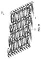
上記で説明した実施形態は実質的に矩形であるが、他の実施形態が矩形でない形状を有することは、当業者には理解されよう。図示の例のように、図26は、「アーチ」型と呼ばれる形状を有するヘッドボード498を示し、図27は、「ラクダの背中」型と呼ばれる形状を有するヘッドボード500を示し、図28は、上隅が丸められた概ね矩形の形状を有するヘッドボード502を示す。図2〜図25に示すような実施形態は、たとえば、図26〜図28に示すような形状を選択的に有してよいことが、了解されよう。
Although the embodiments described above are substantially rectangular, those skilled in the art will appreciate that other embodiments have non-rectangular shapes. As in the illustrated example, FIG. 26 shows a
上記のように、上記で開示した本体は、従来のアップホルスタリー技法を必要とすることなく、またアップホルスターするために他のより煩わしい代替策を必要とすることなく、装飾カバーを保持するヘッドボードシステムの一部を形成することができる。さらに、上記で説明した本体は、たとえば、より一般的に壁を装飾することなど、ヘッドボード以外の用途に対して装飾カバーを保持するために使用される。またさらに、上記で説明した本体は、たとえば図に示すように積み重ねられ、そのような積み重ねは、コンパクトでコスト効果の高い運送を可能にするとともに、隣接する同様の本体間の接触が、運送中の本体を安定させ、そのことで、隣接する本体の相対運動によって生じることがある、運送中の損傷が低減される。さらに、上記で開示したような光源が、上記で開示した本体が装着される壁の外観(visual appearance)を強調することができる。 As noted above, the body disclosed above is a head that holds a decorative cover without the need for conventional upholstery techniques and without the need for other more cumbersome alternatives to upholster. Part of a board system can be formed. Furthermore, the body described above is used to hold a decorative cover for applications other than headboards, such as, for example, more generally for decorating walls. Still further, the bodies described above are stacked, for example as shown in the figure, such stacking allows for compact and cost effective transportation, and contact between adjacent similar bodies is in transit. Of the body, thereby reducing damage during transport that may be caused by relative movement of adjacent bodies. Furthermore, the light source as disclosed above can enhance the visual appearance of the wall on which the body disclosed above is mounted.
再び図1を参照すると、ナイトテーブル92は、床86と接触するために脚504、506、508および510を含む。ナイトテーブル92はまた、床86上で脚504、506、508および510によって支えられる概ね矩形のフレーム512を含み、ナイトテーブル92はまた、概ね矩形のフレーム512内でスライド可能に受けることができるドロワー514を含む。様々な実施形態では、脚504、506、508および510、概ね矩形のフレーム512およびドロワー514のうちの1つまたは複数は、家具装置であるナイトテーブルの実質的に熱可塑性の本体である。そのような実質的に熱可塑性の本体のうちの1つまたは複数が、鋳型の中で形成され、いくつかの実施形態では、耐久性、研磨仕上げおよび様々な色が、炭素樹脂を用いて利用可能であるので、炭素樹脂が望ましい可能性がある。
Referring again to FIG. 1, the night table 92 includes
またさらに、そのような実質的に熱可塑性の本体のうちの1つまたは複数は、その中に組み込まれた、上記で説明した珪藻土製品およびマメ科植物の抽出物のうちの1つまたは複数を含んでもよい。上記で説明した他の実施形態と同様に、熱可塑性材料が、鋳型に注入される前で液相にあるとき、珪藻土、マメ科植物の抽出物、または両方を熱可塑性材料に付加することによって、そのような珪藻土、マメ科植物の抽出物、または両方が、そのような実質的に熱可塑性の本体に組み込まれる。一実施形態では、そのような実質的に熱可塑性の本体の約30重量%が、珪藻土、または珪藻土と1つまたは複数のマメ科植物の抽出物との混合物であってよい。さらに、追加の珪藻土、マメ科植物の抽出物、または両方は、珪藻土をトコジラミなどの動物にさらに露出させるために、たとえば、概ね矩形のフレーム512またはドロワー514の内面など、そのような実質的に熱可塑性の本体の内面に付着されてよい。
Still further, one or more of such substantially thermoplastic bodies may contain one or more of the diatomaceous earth products and legume extracts described above incorporated therein. May be included. Similar to the other embodiments described above, when the thermoplastic material is in the liquid phase before being injected into the mold, by adding diatomaceous earth, legume extract, or both to the thermoplastic material. , Such diatomaceous earth, legume extract, or both are incorporated into such a substantially thermoplastic body. In one embodiment, about 30% by weight of such substantially thermoplastic body may be diatomaceous earth or a mixture of diatomaceous earth and one or more legume extracts. In addition, additional diatomaceous earth, legume extract, or both may be used to further expose the diatomaceous earth to animals such as bed bugs, such as, for example, the generally
代替的な実施形態では、概ね矩形のフレーム512およびドロワー514は、脚504、506、508および510と同様の脚で支持されるテーブル表面プラットフォームによって取り替えられてもよい。そのような一実施形態によれば、家具装置は、上記で説明したように、実質的に熱可塑性の本体、および珪藻土とマメ科植物の抽出物の一方または両方を含むテーブルを含むことができる。
In an alternative embodiment, the generally
さらに図1を参照すると、化粧台94は、概ね矩形のフレーム516と、概ね矩形のフレーム516内でスライド可能に受けることができる、ドロワー518および520など、複数のドロワーとを含む。概ね矩形のフレーム516およびその中でスライド可能に受けることができる複数のドロワーは、上記で説明した概ね矩形のフレーム512およびドロワー514と実質的に同じであってよい。
Still referring to FIG. 1, the dressing table 94 includes a generally
ベッド96は、マットレス98を支持する、概ね矩形のプラットフォーム522を含む。ベッド96はまた、概ね矩形のプラットフォーム522のそれぞれのコーナーにおいて4つの実質的に熱可塑性の本体を含み、そのような実質的に熱可塑性の本体524、526および528を図1に示す。図示の実施形態では、そのような実質的に熱可塑性の本体は概ね円筒形であり、床86に接触するための、かつ床86の上の、概ね矩形のプラットフォーム522と、したがってマットレス98とを支持する支持体として働く。代替的な実施形態では、ベッド96は、そのような支持体として働く、より多いかまたはより少ない実質的に熱可塑性の本体を含むことができる。
上記のように、いくつかの実施形態では、炭素樹脂は所望の色で着色され、炭素樹脂の外から見える表面は、耐久性があり魅力的な研磨仕上げを有する所望の色を示すように研磨されるので、炭素樹脂は、いくつかの家具装置に対して望ましい材料である。さらに、いくつかの実施形態では、1つまたは複数の内面(たとえば、図1に示す概ね矩形のフレーム512および516の内面など、その内面は、ドロワーが概ね矩形のフレームから取り外されると見えるが、そうでなければドロワーによって隠される)は、黒または別の暗色に着色されるなど、暗く着色されてよい。したがって、たとえば珪藻土がそのような内面に塗布されると、珪藻土のより明るい色が、そのような表面上で珪藻土をより見えやすくさせ、そのような表面上にそのような製品がないこと知らせることが容易になる。したがって、いくつかの実施形態では、そのように暗く着色された内面は、そのような内面が、珪藻土または別のより明るく着色された製品で噴霧あるいは処理されているかどうかを目視で判断するのを助けることができ、そのような目視判断は、そのような珪藻土または他の製品の所望の量を様々な家具装置上で確保するために、そのような珪藻土または他の製品を、どこにいつ塗布すべきか判断することを容易にすることができる。
As noted above, in some embodiments, the carbon resin is colored with the desired color and the surface visible from the outside of the carbon resin is polished to exhibit the desired color with a durable and attractive polishing finish. As such, carbon resin is a desirable material for some furniture devices. Further, in some embodiments, one or more inner surfaces (eg, the inner surfaces of the generally
ナイトテーブル92、化粧台94、ベッド96、マットレス98、およびヘッドボードシステム100を上記で説明したが、代替実施形態による様々な家具装置、キットおよびシステムが、それらの中に組み込まれた珪藻土、マメ科植物の抽出物、または両方を含む、1つまたは複数の実質的に熱可塑性の本体を含み、いくつかの実施形態によるそのような家具装置は、トコジラミおよび他の動物の個体数の抑制を助けることができる。したがって、そのような装置、キットおよびシステムの商業的利用は、そのようなベッドルームまたはホテルルームにおいて、たとえば外骨格を有する動物、節足動物、クモ類、昆虫、およびナンキンムシなどの動物の個体数を抑制することを目的として、そのような装置、キットおよびシステムを流通させ、販売し、売り出し、ベッドルームまたはホテルルーム内に配置することを伴う。
While the night table 92, vanity table 94,
さらに、トコジラミは、しばしば、ベッドルームもしくはホテルルームの居住者から、またはベッドルームもしくはホテルルームの居住者の所持品から、ベッドルームもしくはホテルルーム内にもたらされるものと考えられる。同様に、そのような居住者および所持品は、ベッドルームまたはホテルルーム内のベッド、ナイトテーブル、および化粧台のうちの1つまたは複数の上にある可能性があり、したがって、トコジラミは、ベッドルームまたはホテルルーム内のベッド、ナイトテーブル、および化粧台のうちの1つまたは複数において、ベッドルームまたはホテルルーム内にもたらされる可能性があるものと考えられる。また、トコジラミは、ベッドルームまたはホテルルーム内のベッド内に宿る可能性があるものと考えられる。したがって、いくつかの実施形態では、ナイトテーブル92、化粧台94、ベッド96、およびヘッドボードシステム100は、互いに協働して、トコジラミがもたらされるか、またはベッドルームまたはホテルルーム内に宿る可能性のある特定の場所におけるトコジラミを防除することによって、トコジラミの防除をトータルで促進することができる。
Further, bed bugs are often considered to be brought into the bedroom or hotel room from the bedroom or hotel room occupants or from the belongings of the bedroom or hotel room occupants. Similarly, such residents and belongings may be on one or more of the beds, night tables, and vanities in the bedroom or hotel room, and thus It is believed that one or more of the bed, night table, and vanity in the room or hotel room could be brought into the bedroom or hotel room. In addition, bed bugs are considered to have the possibility of dwelling in a bed in a bedroom or hotel room. Thus, in some embodiments, the night table 92, vanity table 94,
具体的な実施形態を説明し、図示したが、そのような実施形態は、本発明を説明するものにすぎず、添付の特許請求の範囲によって解釈される本発明を制限するものではないと見なされるべきである。 While specific embodiments have been described and illustrated, such embodiments are merely illustrative of the invention and are not to be construed as limiting the invention as construed by the appended claims. Should be.
86 床
88 壁
90 家具システム
92 ナイトテーブル
94 化粧台
96 ベッド
98 マットレス
100 ヘッドボードシステム
102 装飾カバー
104 詰め物
106 本体
108 壁取り付け型補強用板材
110 概矩形部
112 外面
114、116、118、120 外側部
122、124、126、128 内面
130、132、134、136 外縁
138 コネクタ
140 陥凹
142 前側面
144 前面
146 外周
148 後側面
150 背面
152 外向きの外側面
154 コネクタ
156 凸部
158 内向面
160 概ね平らな平面部
162 陥凹
164、166、168、170、172、174、176、178、180 貫通孔
182 補強用板材
184、186 比較的広い部分
188、190、192、194、196、198、200 貫通孔
202、204 構想的リブ
206 斜角
208 凸部
214 外側面
216 内向面
218、220、222、224、226、228、230、232、234 追加の凸部
236 キャビティ
238、240、242、244、246、248、250、252、254、256 開口
258、260 凸部
262 前面
264、266 クリップ
268 カール部
270、272 電気スイッチ
274 透光部
276、278 貫通孔
280、282、284、286、288、290 凸部
292 格納コンパートメント
294 開口
296、298 傾き測定デバイス
300 本体
302 前側面
304 前面
306 概ね平らな平面部
308 内向部
310 後側面
312 外向きの外側面
314 第1の部分
316 第2の部分
318 第3の部分
320 相補部
328 前側面
330 後側面
332 前面
334 外周
336 概ね平らな平面部
338 内向部
340 外向きの外側面
342 背面
344、346 貫通孔
348、350 補強用板材
352、354、356 凸部
358、360、362 貫通孔
364、366、368 凸部
370 壁取り付け型補強用板材
372、374、376 凸部
378、380、382 貫通孔
384 コネクタ
386、388 貫通孔
390、392 概ね直線的な部材
394、396 クリップ
398 格納コンパートメント
400 着脱可能なカバー
402、406、408、410 追加の凸部
412、430 本体 本体
414 後側面
416、418 構造的補強リブ
432、434 概ね直線的な部材
436 本体
438 後側面
440 背面
442、444、446、448、450 貫通孔
452、454、458 はす縁
456 フレンチクリート
460、462 貫通孔
464 傾き測定デバイス
468 前側面
476 後側面
478、480、482、484 レセプタクル
486、488 支持体
490、494 露出した端部
492、496 貫通孔
498、500、502 ヘッドボード
504、506、508、510 脚
512、516 概ね矩形のフレーム
514、518、520 ドロワー
522 概ね矩形のプラットフォーム
524、526、528 実質的に熱可塑性の本体
86 Floor 88 Wall 90 Furniture system 92 Night table 94 Dressing table 96 Bed 98 Mattress 100 Headboard system 102 Decoration cover 104 Stuffing 106 Main body 108 Wall-mounted reinforcing plate 110 Roughly rectangular portion 112 Outer surface 114, 116, 118, 120 Outer portion 122, 124, 126, 128 Inner surface 130, 132, 134, 136 Outer edge 138 Connector 140 Depression 142 Front side 144 Front surface 146 Outer surface 148 Rear side 150 Back surface 152 Outward outer surface 154 Connector 156 Protruding portion 158 Inward surface 160 Generally flat Flat portion 162 Depression 164, 166, 168, 170, 172, 174, 176, 178, 180 Through hole 182 Reinforcement plate material 184, 186 Relatively wide portion 188, 190, 192, 194, 19 , 198, 200 Through hole 202, 204 Conceptual rib 206 Bevel angle 208 Convex part 214 Outer side surface 216 Inward surface 218, 220, 222, 224, 226, 228, 230, 232, 234 Additional convex part 236 Cavity 238, 240 242, 244, 246, 248, 250, 252, 254, 256 Opening 258, 260 Convex part 262 Front face 264, 266 Clip 268 Curl part 270, 272 Electric switch 274 Translucent part 276, 278 Through hole 280, 282, 284 286, 288, 290 Convex 292 Storage compartment 294 Opening 296, 298 Inclination measuring device 300 Main body 302 Front side 304 Front 306 General flat surface 308 Inward part 310 Rear side 312 Outward outer side 314 First part 316 2 part 318 3rd part 320 Complementary part 328 Front side 330 Rear side 332 Front side 334 Outer periphery 336 Flat surface part 338 Inward part 340 Outer side outer side 342 Back side 344, 346 Through hole 348, 350 Reinforcing plate 352 354, 356 Protruding part 358, 360, 362 Through hole 364, 366, 368 Protruding part 370 Wall mounting type reinforcing plate 372, 374, 376 Convex part 378, 380, 382 Through hole 384 Connector 386, 388 Through hole 390, 392 General linear member 394, 396 Clip 398 Storage compartment 400 Removable cover 402, 406, 408, 410 Additional convex part 412, 430 Main body Main body 414 Rear side 416, 418 Structural reinforcement rib 432, 434 General linear 436 materials 438 Rear side 440 Rear side 442, 444, 446, 448, 450 Through hole 452, 454, 458 Lotus edge 456 French cleat 460, 462 Through hole 464 Inclination measuring device 468 Front side 476 Rear side 478, 480, 482, 484 Receptacle 486, 488 Support 490, 494 Exposed end 492, 496 Through hole 498, 500, 502 Headboard 504, 506, 508, 510 Leg 512, 516 General rectangular frame 514, 518, 520 Drawer 522 General rectangular platform 524, 526, 528 substantially thermoplastic body
Claims (77)
前側面と、対向する後側面と、を有する本体であって、前記本体の前記前側面が外周を有する前面を有し、前記本体の前記後側面が背面を有し、前記本体が前記前面と背面との間に外向きの外側面を有する本体と、
前記装飾カバー上の、第1のコネクタと相補的な第2のコネクタに対して、前記前面の前記外周の少なくとも一部分に連続的に隣接して着脱可能に接続できる、前記本体上の第1の接続部と、
を備える装置。 In the device that holds the decorative cover,
A main body having a front side surface and an opposing rear side surface, wherein the front side surface of the main body has a front surface having an outer periphery, the rear side surface of the main body has a back surface, and the main body has the front surface A body having an outwardly facing outer surface between the back surface;
A first connector on the body that is detachably connectable to a second connector on the decorative cover that is complementary to the first connector and that is continuously adjacent to at least a portion of the outer periphery of the front surface; A connection,
A device comprising:
前記前面の前記概ね平らな平面部および前記前面の前記内向部が、前記陥凹を画定する請求項22または23に記載の装置。 The front surface comprises a generally flat planar portion and an inward portion between the generally planar planar portion and the outer surface of the body;
24. The apparatus of claim 22 or 23, wherein the generally flat planar portion of the front surface and the inward portion of the front surface define the recess.
前記外側面の少なくとも一部分が、前記隣接する同様の装置の前記前面の前記内向部の少なくとも一部分に接触すると、前記隣接する同様の装置が前記本体の前記後側面に対して積み重ね可能となるように、前記外側面の少なくとも一部分が、前記隣接する同様の装置の前記前面の前記内向部の少なくとも一部分に接触するように位置づけられる請求項24に記載の装置。 The body defines a first protrusion having the outer surface of the front surface and the inward portion;
The adjacent similar device can be stacked against the rear side of the body when at least a portion of the outer surface contacts at least a portion of the inward portion of the front surface of the adjacent similar device. 25. The device of claim 24, wherein at least a portion of the outer surface is positioned to contact at least a portion of the inward portion of the front surface of the adjacent similar device.
前記装飾カバーと、
を備えるキット。 34. The device according to any one of claims 1 to 33;
The decorative cover;
A kit comprising:
前記詰め物と、
前記装飾カバーと、
を備えるキット。 A device according to any one of claims 22 to 27 or any one of claims 28 to 33 when dependent on claim 22;
The stuffing;
The decorative cover;
A kit comprising:
前記装飾カバーと、
を備え、
前記装飾カバーが、前記本体の前記前面の前記外周によって囲まれる前記本体の前記前面の少なくとも一部分を覆うように、前記第1のコネクタが前記第2のコネクタに接続されるシステム。 34. The device according to any one of claims 1 to 33;
The decorative cover;
With
A system in which the first connector is connected to the second connector such that the decorative cover covers at least a portion of the front surface of the body surrounded by the outer periphery of the front surface of the body.
前記詰め物と、
前記装飾カバーと、
を備え、
前記装飾カバーが、前記本体の前記前面の前記外周によって囲まれる前記本体の前記前面の少なくとも一部分を覆うように、かつ前記装飾カバーが、前記本体と前記装飾カバーとの間でかつ詰め物を受けるための前記陥凹の中で前記詰め物を保持するように、前記第1のコネクタが前記第2のコネクタに接続されるシステム。 A device according to any one of claims 22 to 27 or any one of claims 28 to 33 when dependent on claim 22;
The stuffing;
The decorative cover;
With
The decorative cover covers at least a portion of the front surface of the main body surrounded by the outer periphery of the front surface of the main body, and the decorative cover receives the padding between the main body and the decorative cover. A system in which the first connector is connected to the second connector so as to retain the padding in the recess.
前記少なくとも1つの本体のうちの1つまたは複数の中に組み込まれたPA1b関連ペプチドと、
を備える家具装置。 At least one substantially thermoplastic body;
A PA1b-related peptide incorporated into one or more of said at least one body;
A furniture device comprising:
前記少なくとも1つの本体のうちの1つまたは複数の中に組み込まれた珪藻土と、
を備える家具装置。 At least one substantially thermoplastic body;
Diatomaceous earth incorporated in one or more of the at least one body;
A furniture device comprising:
Applications Claiming Priority (5)
| Application Number | Priority Date | Filing Date | Title |
|---|---|---|---|
| US201161482067P | 2011-05-03 | 2011-05-03 | |
| US61/482,067 | 2011-05-03 | ||
| US201161563220P | 2011-11-23 | 2011-11-23 | |
| US61/563,220 | 2011-11-23 | ||
| PCT/CA2012/000389 WO2012149636A1 (en) | 2011-05-03 | 2012-04-26 | Furniture apparatuses, and kits, systems, and uses of same |
Publications (2)
| Publication Number | Publication Date |
|---|---|
| JP2014518694A true JP2014518694A (en) | 2014-08-07 |
| JP2014518694A5 JP2014518694A5 (en) | 2015-06-18 |
Family
ID=47107705
Family Applications (1)
| Application Number | Title | Priority Date | Filing Date |
|---|---|---|---|
| JP2014508655A Pending JP2014518694A (en) | 2011-05-03 | 2012-04-26 | Furniture equipment and kits, systems and their use |
Country Status (6)
| Country | Link |
|---|---|
| US (3) | US20140084774A1 (en) |
| EP (1) | EP2704610A4 (en) |
| JP (1) | JP2014518694A (en) |
| CN (1) | CN103687514A (en) |
| CA (2) | CA3007796C (en) |
| WO (1) | WO2012149636A1 (en) |
Families Citing this family (10)
| Publication number | Priority date | Publication date | Assignee | Title |
|---|---|---|---|---|
| EP2704610A4 (en) | 2011-05-03 | 2014-10-01 | Roderick William Phillips | Furniture apparatuses, and kits, systems, and uses of same |
| US9220254B2 (en) * | 2011-09-21 | 2015-12-29 | Dahai Dong | Bed bug trap or barrier surrounding a bed |
| AU2012343291B2 (en) | 2011-11-23 | 2016-09-15 | Roderick William PHILLIPS | Spray apparatuses, uses of diatomaceous earth, and methods of controlling insect populations |
| SE536678C2 (en) * | 2012-02-02 | 2014-05-20 | Nattaro Labs Ab | Device for detecting and eliminating insects such as bedbugs |
| CA2847388A1 (en) * | 2014-03-21 | 2015-09-21 | Roderick William PHILLIPS | Diatomaceous earth intermixed with a colouring agent, and spray apparatuses, uses, and methods involving same |
| US10091980B1 (en) * | 2015-06-05 | 2018-10-09 | Thomas Paul Cogley | Bed bug detector system |
| US10021869B1 (en) * | 2015-06-05 | 2018-07-17 | Thomas Paul Cogley | Mosquito destructor system |
| US20170074307A1 (en) * | 2015-09-11 | 2017-03-16 | Anthony R. SLAGLE | Methods, systems and components for designing and/or assembling a shelving unit |
| US10401020B2 (en) * | 2015-11-13 | 2019-09-03 | Brightz ltd. | Apparatus for illuminating outdoor bag toss game |
| US10736309B1 (en) * | 2018-11-27 | 2020-08-11 | Thomas Paul Cogley | Bed bug detector system |
Citations (7)
| Publication number | Priority date | Publication date | Assignee | Title |
|---|---|---|---|---|
| JPS60241406A (en) * | 1984-05-12 | 1985-11-30 | 大塚化学株式会社 | Insect-proof method of furniture |
| JPH03165713A (en) * | 1989-11-27 | 1991-07-17 | Tadao Isshiki | Bed core material and bed therewith |
| JPH08173296A (en) * | 1994-12-22 | 1996-07-09 | France Bed Co Ltd | Covering bed |
| JPH10151038A (en) * | 1996-11-21 | 1998-06-09 | Tadao Isshiki | Bed with head board |
| JP2004049366A (en) * | 2002-07-17 | 2004-02-19 | Matsushita Electric Ind Co Ltd | Kitchen panel |
| JP2010208994A (en) * | 2009-03-10 | 2010-09-24 | Panefuri Kogyo Kk | Pest-controlling agent and method for controlling insect pest using composite insect pest control agent using bidens plant and insect pest control method |
| JP2011524874A (en) * | 2008-06-20 | 2011-09-08 | ビーエーエスエフ ソシエタス・ヨーロピア | Agrochemical formulation containing pesticide, organic UV light protection filter and coated metal oxide nanoparticles |
Family Cites Families (196)
| Publication number | Priority date | Publication date | Assignee | Title |
|---|---|---|---|---|
| US457931A (en) * | 1891-08-18 | Bed-lounge | ||
| US1569710A (en) | 1924-08-29 | 1926-01-12 | Arthur G Burt | Dog mat |
| US2095459A (en) * | 1935-02-04 | 1937-10-12 | Elizabeth M Tottenham | End mattress |
| US2508506A (en) * | 1946-12-09 | 1950-05-23 | Annette E Fridolph | Decorative furniture panel construction |
| GB658221A (en) | 1948-06-15 | 1951-10-03 | Goodrich Co B F | Improvements in or relating to insecticidal compositions and insect control |
| US2579157A (en) * | 1948-08-02 | 1951-12-18 | Price Building Specialties Co | Panel construction |
| US2671910A (en) * | 1948-08-06 | 1954-03-16 | Superior Sleeprite Corp | Headboard for beds |
| GB673877A (en) | 1949-10-18 | 1952-06-11 | Dow Chemical Co | Diamido-thiophosphates and parasiticidal compositions comprising same |
| US2687537A (en) | 1951-08-14 | 1954-08-31 | Hettrick Mfg Co | Decorated headboard for beds |
| GB803611A (en) * | 1954-10-07 | 1958-10-29 | Horatio Myer And Company Ltd | Improvements in beds |
| US2968850A (en) * | 1958-03-10 | 1961-01-24 | George A Tinnerman | Supporting clamps |
| US3000779A (en) | 1958-08-05 | 1961-09-19 | Phillips Petroleum Co | Insect combatting sulfoxides |
| US3010615A (en) | 1960-02-24 | 1961-11-28 | Detrex Chem Ind | Automatic filter powder dispenser |
| US3062709A (en) | 1960-08-30 | 1962-11-06 | Velsicol Chemical Corp | Insecticide formulations |
| US3165441A (en) | 1961-03-01 | 1965-01-12 | Monsanto Co | Methylphosphonothioate insecticide |
| GB989014A (en) | 1961-03-01 | 1965-04-14 | Monsanto Co | Thiophosphonates and compositions containing the same |
| US3082147A (en) | 1961-03-03 | 1963-03-19 | Monsanto Chemicals | Insecticidal o-(aryl) phosphonothioates |
| GB998604A (en) | 1961-03-03 | 1965-07-14 | Monsanto Co | Thiophosphonates and compositions containing the same |
| US3082148A (en) | 1961-03-06 | 1963-03-19 | Monsanto Chemicals | Insecticidal phosphonothioates |
| US3132769A (en) | 1962-03-14 | 1964-05-12 | Westinghouse Electric Corp | Powder dispensing device |
| US3290198A (en) * | 1963-10-23 | 1966-12-06 | Haveg Industries Inc | Method of forming a series of unfilled containers from thermoplastic tubing |
| US3306499A (en) | 1965-05-06 | 1967-02-28 | Norman R Lykes | Powder distributor |
| GB1289308A (en) * | 1968-12-24 | 1972-09-13 | ||
| US3652425A (en) | 1969-02-18 | 1972-03-28 | Wilson Lab Inc | Process for the preparation of heteropoly acid complex compounds of metaphosphoric metasilic acid, metaphosphoric acid and phosphorous pentoxide |
| US3676279A (en) * | 1970-06-16 | 1972-07-11 | All Steel Equipment Inc | Sandwich top construction for office furniture |
| US3736603A (en) * | 1972-03-17 | 1973-06-05 | L Rothman | Child{40 s plush figure headboard |
| US3878147A (en) | 1973-12-27 | 1975-04-15 | Du Pont | Composition for increasing the friction of surfaces on ice |
| EG11837A (en) | 1974-09-19 | 1977-12-31 | Lilly Co Eli | Novel 1-(substituted benzoyl)-3-(substituted pyrazinyl ureas used as insecticides |
| US3992839A (en) * | 1974-11-21 | 1976-11-23 | Ethyl Corporation | Snap-on paneling |
| US4008688A (en) | 1975-12-17 | 1977-02-22 | Nicholas Dimitri P | Pet bed |
| US4098435A (en) | 1976-08-16 | 1978-07-04 | Colgate-Palmolive Company | Stabilized dentrifice containing initially physically separated normally reactive components |
| US4279895A (en) | 1979-07-13 | 1981-07-21 | Arthur Carle | Insecticidal natural bait composition and method of using same |
| CA1112158A (en) | 1981-01-08 | 1981-11-10 | Arthur Carle | Insecticidal natural bait composition and method of using same |
| US4526305A (en) | 1981-01-08 | 1985-07-02 | Lykes Norman R | Apparatus for manually distributing powder granules |
| GB2107978A (en) * | 1981-10-21 | 1983-05-11 | Yolande Sarah Fligelstone | Improvements relating to bed headboards |
| USD286378S (en) | 1983-08-15 | 1986-10-28 | Banfield Michael G | Packaging container |
| WO1986000658A1 (en) * | 1984-07-06 | 1986-01-30 | Geoffrey Ballantyne Ashton | Space divider |
| GB2180449A (en) * | 1985-09-18 | 1987-04-01 | Slumberland Ltd | A quilt for a bed |
| US4702046A (en) * | 1985-11-08 | 1987-10-27 | General Communications, Inc. | Acoustical wall panel |
| US4683674A (en) * | 1985-11-15 | 1987-08-04 | Barclay Horticulture Mfg. Ltd. | Compost bin |
| US4810590A (en) * | 1987-02-19 | 1989-03-07 | Phillips Petroleum Company | Poly(arylene sulfide) encapsulation process and article |
| US4821349A (en) * | 1987-02-20 | 1989-04-18 | Elaine S. Cohen | Fabric covered knock-down headboard for beds |
| US4732430A (en) * | 1987-02-26 | 1988-03-22 | Byrns James E | Blow molded drawer front |
| US4871218A (en) * | 1987-10-20 | 1989-10-03 | Swinson Owen I | Collapsible storage and display device |
| US4964231A (en) * | 1988-06-10 | 1990-10-23 | Silent Sound Systems, Inc. | Front-mount grid frame |
| CA1286219C (en) | 1989-06-08 | 1991-07-16 | John W. Tucker | Insecticidal bait composition and method for making same |
| US4957395A (en) * | 1989-06-19 | 1990-09-18 | Ned Nelson | Pre-cast, reinforced concrete retaining wall system |
| JP2715582B2 (en) | 1989-08-03 | 1998-02-18 | 松下電器産業株式会社 | Power control device |
| EP0412832A3 (en) * | 1989-08-11 | 1992-03-04 | Nippon Petrochemicals Company, Limited | Graft-modified substance, process for preparing same, and thermoplastic resin composition using the graft-modified substance |
| US5074348A (en) | 1989-09-25 | 1991-12-24 | Phillips Roderick W | Adjustable valence system for a window |
| US5346296A (en) | 1990-04-06 | 1994-09-13 | Sligh Furniture Co. | Assembly of wall units with concealed wire storage |
| US5176435A (en) | 1990-11-19 | 1993-01-05 | Interchangeable Design Systems, Inc. | Interchangeable modular furniture system |
| CA2098275A1 (en) * | 1990-12-19 | 1992-06-20 | Waldemar E. Wittler | Interlocking structural members with edge connectors |
| US5308613A (en) | 1991-03-14 | 1994-05-03 | Consep Membranes, Inc. | Indirect aphid control with low concentration of EBF |
| CA2060379A1 (en) * | 1992-01-30 | 1993-07-31 | Peter R. Pitchford | Interlocking building block |
| US5195195A (en) * | 1992-10-05 | 1993-03-23 | Murray James J | Headboard |
| US5269032A (en) * | 1992-10-23 | 1993-12-14 | John Flocks | Portable, readily assembled, easily upholstered headboard |
| US5439690A (en) | 1993-05-21 | 1995-08-08 | Ecosmart, Inc. | Non-hazardous pest control |
| US6713518B1 (en) | 1993-05-21 | 2004-03-30 | Ecosmart Technologies, Inc. | Non-hazardous pest control |
| US6004569A (en) | 1993-05-21 | 1999-12-21 | Ecosmart Technologies, Inc. | Non-hazardous pest control |
| US6534099B1 (en) | 1993-05-21 | 2003-03-18 | Ecosmart Technologies, Inc. | Pesticidal compositions containing menthyl salicylate |
| US6114384A (en) | 1993-05-21 | 2000-09-05 | Ecosmart, Inc. | Non-hazardous pest control |
| US5529380A (en) * | 1994-06-07 | 1996-06-25 | Aaa Mine Service, Inc. | Apparatus and method for forming a frame for an article of furniture |
| US5653072A (en) * | 1994-09-22 | 1997-08-05 | Seelandt-Stasek; Lisa | Universal window sill tray |
| US5784843A (en) | 1994-12-30 | 1998-07-28 | Steelcase Inc. | Integrated prefabricated furniture system for fitting-out open plan building space |
| US6128873A (en) | 1994-12-30 | 2000-10-10 | Steelcase Development Inc. | Integrated prefabricated furniture system for fitting-out open plan building space |
| CA2149164C (en) | 1995-05-11 | 2009-03-03 | Zlatko Korunic | Diatomaceous earth insecticidal composition |
| BR9609114A (en) | 1995-05-11 | 1999-12-14 | Canada Agriculture | Insecticidal composition of diatomaceous earth |
| US5950386A (en) | 1995-12-26 | 1999-09-14 | Steelcase Inc. | Partition construction having frame and misaligned covers |
| JP3197216B2 (en) | 1996-07-02 | 2001-08-13 | 株式会社日阪製作所 | Tray used for heat sterilization of plastic containers |
| BR9715000A (en) | 1996-09-25 | 2001-09-18 | Aquatrol Corp | Processes for preparing pesticide vehicles that spontaneously disperse in water and the use of these |
| AU4392597A (en) | 1996-09-25 | 1998-04-17 | Rhone-Poulenc, Inc. | Spontaneously water dispersible carrier for pesticides |
| US6240879B1 (en) | 1997-04-15 | 2001-06-05 | Seefar Technologies, Inc. | Amusement articles possessing microbe-inhibiting properties |
| RU2199212C2 (en) | 1997-08-22 | 2003-02-27 | Плааскэм (Пропрайэтэри) Лимитед | Dosed form, method for manufacturing the same, object processing method |
| US5881508A (en) * | 1997-10-15 | 1999-03-16 | Materials International, Inc. | Decking extrusion |
| US6263529B1 (en) * | 1998-01-28 | 2001-07-24 | Mitchell G. Alexander | Cubicle bed having transparent, minimally restrictive barriers |
| JP3920452B2 (en) | 1998-04-07 | 2007-05-30 | アース製薬株式会社 | Pest repellent aerosol |
| US5937587A (en) * | 1998-04-20 | 1999-08-17 | Sun Hill Industries, Inc. | Garage door decorative cover assembly |
| US6849614B1 (en) | 1998-07-28 | 2005-02-01 | Ecosmart Technologies, Inc. | Synergistic and residual pesticidal compositions containing plant essential oils |
| US6986898B1 (en) | 1999-06-28 | 2006-01-17 | Ecosmart Technologies, Inc. | Synergistic and residual pesticidal compositions containing plant essential oils with enzyme inhibitors |
| US20030194454A1 (en) | 1998-07-28 | 2003-10-16 | Bessette Steven M. | Pesticidal compositions containing rosemary oil and wintergreen oil |
| MXPA01000697A (en) | 1998-07-28 | 2002-04-08 | Ecosmart Technologies Inc | Synergistic and residual pesticidal compositions containing plant essential oils. |
| AU5920399A (en) | 1998-09-15 | 2000-04-03 | Jack H. Bates | Persistent diatomaceous earth molluskicidial composition |
| JP2000176370A (en) | 1998-12-15 | 2000-06-27 | Teddo:Kk | Wooden closet with deodorant, insectproof and moistureproof coating |
| CA2264383A1 (en) | 1999-03-03 | 2000-09-03 | Zlatko Korunic | Low toxicity insecticides |
| US6405491B1 (en) | 1999-04-22 | 2002-06-18 | Hill-Rom Services, Inc. | Modular patient room |
| US8256135B2 (en) | 1999-05-28 | 2012-09-04 | Thermapure, Inc. | Method for removing or treating harmful biological and chemical substances within structures and enclosures |
| US6531163B1 (en) | 1999-06-28 | 2003-03-11 | Ecosmart Technologies, Inc. | Pesticidal compositions containing peppermint oil |
| US6182307B1 (en) * | 1999-08-31 | 2001-02-06 | Julius Rutrick | Wall mounted headboard for a bed |
| EP1408762A2 (en) | 2000-02-17 | 2004-04-21 | Ecosmart Technologies, Inc. | Plant essential oils containing pediculicidal compositions |
| JP4666716B2 (en) * | 2000-05-26 | 2011-04-06 | 株式会社ダイゾー | Aerosol products |
| US6371190B1 (en) | 2000-06-16 | 2002-04-16 | Rene D. Owens | Decor unit and method for mounting same on a wall |
| AU2001280626A1 (en) * | 2000-07-18 | 2002-01-30 | Donald J. Mischo | Modular green roof system with pre-seeded panels |
| GB2370224B (en) | 2000-11-03 | 2004-10-06 | Second Nature U K Ltd | Protection of natural fibres from attack by insects |
| JP2002337114A (en) * | 2001-05-18 | 2002-11-27 | Annaka Seisakusho:Kk | Laminated type decorative board |
| US20030056587A1 (en) | 2001-09-19 | 2003-03-27 | Carpenter M. Scott | Thermochromatic indicator for an aersol container |
| US20030061758A1 (en) | 2001-09-28 | 2003-04-03 | Wilson Harold W. | Composition and method for exterminating subterranean burrowing air-breathing pests |
| US6543071B1 (en) | 2001-09-28 | 2003-04-08 | Mary J. Lenner | Furniture from childhood to adulthood using interchangeable panels |
| US6394321B1 (en) | 2001-12-20 | 2002-05-28 | Precision Valve Corporation | Aerosol powder valve |
| US6550083B1 (en) * | 2002-01-07 | 2003-04-22 | Lamantia Mark | Crib and playpen protective covering |
| US6618876B2 (en) | 2002-01-18 | 2003-09-16 | Stephen Murphy | Wall-hung decorative headboard for a bed |
| US6658677B2 (en) | 2002-02-01 | 2003-12-09 | P. J. Kids, Llc | System for replacing decorative furniture panels |
| US20040109853A1 (en) | 2002-09-09 | 2004-06-10 | Reactive Surfaces, Ltd. | Biological active coating components, coatings, and coated surfaces |
| US20100215705A1 (en) * | 2002-12-20 | 2010-08-26 | Bioguard Research And Development, Inc. | Use of Colloidal Clays for Sustained Release of Active Ingredients |
| GB0300797D0 (en) | 2003-01-14 | 2003-02-12 | Second Nature U K Ltd | Insect proofing of carpets |
| US6998433B2 (en) * | 2003-02-27 | 2006-02-14 | Rehig Pacific Company | Flame retardant polyolefin pallets and flame retardant master batch for their production |
| US6799337B1 (en) * | 2003-04-15 | 2004-10-05 | Danielle Raphael-Davis | Baby crib attachments |
| US7216686B2 (en) * | 2003-04-22 | 2007-05-15 | June Tailor, Inc. | Cornice system |
| CN1550177A (en) * | 2003-05-14 | 2004-12-01 | 曹茂铉 | Mattress integrated stone bed |
| JP4368635B2 (en) | 2003-08-01 | 2009-11-18 | 株式会社クラレ | Pest control method and control agent |
| US7434365B2 (en) * | 2003-09-03 | 2008-10-14 | Gary Robert Geller | Drawer or door front assembly |
| US7744298B2 (en) | 2003-10-16 | 2010-06-29 | Permatex, Inc. | Gelled composition applicator |
| US20050132500A1 (en) | 2003-12-22 | 2005-06-23 | Basf Aktiengesellschaft | Composition for impregnation of fibers, fabrics and nettings imparting a protective activity against pests |
| US7387151B1 (en) | 2004-01-23 | 2008-06-17 | Payne Donald L | Cabinet door with changeable decorative panel |
| US7614298B2 (en) | 2004-03-15 | 2009-11-10 | Display Matrix Corporation | Opaque aerosol container capacity indicator |
| US20050255139A1 (en) * | 2004-05-14 | 2005-11-17 | Hurd Jonathan L | Polymeric compositions with embedded pesticidal desiccants |
| WO2005115341A2 (en) | 2004-05-27 | 2005-12-08 | Advanced Bionutrition Corporation | Microparticles for oral delivery |
| JP2008501877A (en) | 2004-06-03 | 2008-01-24 | ヒル−ロム サービシーズ,インコーポレイティド | Family zone module for hospital walls |
| US7469512B2 (en) | 2004-06-22 | 2008-12-30 | Board of Regents of the University of Nebraska by and behalf of University of Nebraska Medical Center | Fabricated wall system |
| CN2750730Y (en) * | 2004-07-20 | 2006-01-11 | 钱品兴 | Novel hollow plastic headboard |
| US7838589B2 (en) * | 2004-07-21 | 2010-11-23 | Zephyros, Inc. | Sealant material |
| US7159253B2 (en) | 2004-08-17 | 2007-01-09 | American Signature, Inc. | Modular headboard and method of assembly |
| US7118179B1 (en) | 2004-09-17 | 2006-10-10 | Wilson Stephanie W | Portable wall mounted headboard |
| US7487558B2 (en) * | 2004-12-23 | 2009-02-10 | Hill-Rom Services, Inc. | Headboard for a pull-up-in-bed system |
| US20060216367A1 (en) * | 2005-03-24 | 2006-09-28 | Her Majesty The Queen In Right Of Canada, The Minister Of Agriculture And Agri-Food | Insecticidal extract from legume plants and method of preparing the same |
| CN100531624C (en) | 2005-04-29 | 2009-08-26 | 清展科技股份有限公司 | Insect-expelling screen and production thereof |
| US20060270561A1 (en) | 2005-05-24 | 2006-11-30 | Keim William A | Compositions for use in stored crop treatment aerosols and method and apparatus for application to stored crops |
| US7490509B2 (en) | 2005-09-16 | 2009-02-17 | Display Matrix Corporation | Opaque aerosol container capacity indicator |
| US20070094794A1 (en) * | 2005-11-01 | 2007-05-03 | Keturrah Ellis | Scented disposable bed liner and pillow liner |
| US20070164059A1 (en) | 2006-01-19 | 2007-07-19 | Rosiello Keith M | Powder delivery device |
| CN200983804Y (en) | 2006-04-06 | 2007-12-05 | 河南未来机电工程有限公司 | Mobile type bergmeal powder gun |
| CA2652032A1 (en) | 2006-05-11 | 2008-05-29 | Dentsply International Inc. | Aerosol delivery system for dispensing dental compositions |
| GB0612788D0 (en) | 2006-06-28 | 2006-08-09 | Insectshield Ltd | Pest control materials |
| CN101147643B (en) * | 2006-09-21 | 2012-04-18 | 卢正国 | Guard bar on big bed for baby |
| US8104853B2 (en) * | 2006-12-19 | 2012-01-31 | Samsung Electronics Co., Ltd. | Refrigerator and method of manufacturing door thereof |
| WO2008078413A1 (en) | 2006-12-22 | 2008-07-03 | Unitika Ltd. | Biodegradable polyester resin composition, and molded body, foamed body and molded container obtained from the biodegradable polyester resin composition |
| US7579396B2 (en) * | 2007-01-31 | 2009-08-25 | Eastman Kodak Company | Polymer composite |
| US20080193387A1 (en) | 2007-02-14 | 2008-08-14 | Ricki De Wolff | Essential oil compositions for killing or repelling ectoparasites and pests and methods for use thereof |
| CN201012152Y (en) * | 2007-04-05 | 2008-01-30 | 上海品兴科技有限公司 | Improved multifunctional turning-over bed |
| WO2008154605A1 (en) * | 2007-06-11 | 2008-12-18 | Dream-Ezzz International, Llc. | Treated bedding cover |
| CN101327085A (en) | 2007-06-18 | 2008-12-24 | 际诺思(厦门)轻工制品有限公司 | Sponge |
| US7640610B2 (en) * | 2007-07-27 | 2010-01-05 | Lante Medical, Inc. | Upper extremity support |
| US7723428B2 (en) * | 2007-07-31 | 2010-05-25 | Sabic Innovative Plastics Ip B.V. | Polycarbonate compositions with improved molding capability |
| CN101381473A (en) * | 2007-09-07 | 2009-03-11 | 许连祥 | Method of preparing thermoplastic hard foam |
| EP2207416B1 (en) | 2007-10-02 | 2018-11-07 | Imerys Filtration Minerals, Inc. | Enhanced retention capabilities through methods comprising surface treatment of functional particulate carrier materials, and functional particulate carrier materials made therefrom |
| CN101952525A (en) | 2007-10-30 | 2011-01-19 | 世界矿物公司 | Modified mineral-based fillers |
| US8205378B2 (en) | 2007-11-21 | 2012-06-26 | Springstar Inc. | Trap for flying insects |
| US20090222995A1 (en) | 2008-03-05 | 2009-09-10 | Bernard Perry | Bedding Applications for Porous Material |
| GB2458222A (en) | 2008-03-14 | 2009-09-16 | Bissell Homecare Inc | Aerosol dispenser with pouch containing cleaning fluid |
| US20090233940A1 (en) | 2008-03-17 | 2009-09-17 | George Taylor | Insecticide Compositions |
| CN102036668A (en) | 2008-03-19 | 2011-04-27 | 蒂拉德克公司 | Pest control compositions and methods |
| BRPI0910268B8 (en) | 2008-03-19 | 2021-05-25 | Tyratech Inc | composition for controlling a target pest, antiparasitic formulation, use of said composition, and method for producing an improved agent for controlling a target pest |
| US20090269381A1 (en) | 2008-04-23 | 2009-10-29 | Grain Processing Corporation | Pest Control Agent |
| US8024889B2 (en) | 2008-06-25 | 2011-09-27 | Brett Bunker | Pest control method and apparatus |
| US20100127224A1 (en) | 2008-09-30 | 2010-05-27 | Ryan Neff | Atmospheric injection of reflective aerosol for mitigating global warming |
| WO2010064342A1 (en) * | 2008-12-04 | 2010-06-10 | シャープ株式会社 | Transfer tray |
| US9834684B2 (en) | 2009-03-11 | 2017-12-05 | Imerys Filtration Minerals, Inc. | Natural amorphous silica filler products |
| CN201375245Y (en) * | 2009-03-19 | 2010-01-06 | 王述洋 | Multi-functional bed |
| US8551235B2 (en) | 2009-04-23 | 2013-10-08 | Green Wave Innovative Solutions, Llc | Algae based fire resistant materials and method of making same |
| US8440009B2 (en) | 2009-04-23 | 2013-05-14 | Green Wave Innovative Solutions, Llc | Cladophora based materials and method of making same |
| US20110236589A1 (en) | 2009-09-14 | 2011-09-29 | Mark Streisfeld | Novel pest repellant and pesticide composition and method of use |
| AU2010337357B2 (en) * | 2009-12-31 | 2013-11-28 | Arelac, Inc. | Methods and compositions using calcium carbonate |
| CN201641161U (en) * | 2010-01-29 | 2010-11-24 | 深圳市汇益德环保材料有限公司 | Bed with diatom mud coating |
| US20130025185A1 (en) | 2010-04-12 | 2013-01-31 | O'connor Lee Zeke | Crawling insect barrier |
| EP2377395A1 (en) | 2010-04-15 | 2011-10-19 | Bayer CropScience AG | Non-woven fabric containing insecticide |
| WO2011146663A2 (en) * | 2010-05-18 | 2011-11-24 | Kiltronx Enviro Systems, Llc | Materials, methods, and apparatuses for controlling pests |
| US20120167309A1 (en) | 2010-12-30 | 2012-07-05 | Heidorn Brian D | Bed bug monitoring device |
| GB201100621D0 (en) | 2011-01-14 | 2011-03-02 | Insectshield Ltd | Three-dimensional material |
| US20120227313A1 (en) | 2011-03-11 | 2012-09-13 | Fxi, Inc. | Crawling insect (bed bug and mite) abatement system and method |
| US20120258150A1 (en) * | 2011-04-11 | 2012-10-11 | Holly Balasubramanian Rauckhorst | Particles comprising volatile materials and particle gas saturated solution processes for making same |
| EP2704610A4 (en) | 2011-05-03 | 2014-10-01 | Roderick William Phillips | Furniture apparatuses, and kits, systems, and uses of same |
| US8808721B2 (en) | 2011-05-09 | 2014-08-19 | Springstar Inc. | Bed bug attractants and methods for trapping bed bugs |
| CN104144624B (en) | 2011-09-30 | 2019-02-15 | 汉斯·O·里比 | Higher element medical disposable material product |
| AU2012320093B2 (en) | 2011-10-04 | 2017-07-13 | 0903608 B.C. Ltd. | Pest control formulations and methods of making and using same |
| US20130089578A1 (en) | 2011-10-11 | 2013-04-11 | Winfield Solutions, Llc | Liquid insecticide including diatomaceous earth |
| AU2012343291B2 (en) | 2011-11-23 | 2016-09-15 | Roderick William PHILLIPS | Spray apparatuses, uses of diatomaceous earth, and methods of controlling insect populations |
| US20140323539A1 (en) | 2011-12-05 | 2014-10-30 | Basf Se | Emulsifiable Concentrate Comprising Pesticide, Dimethyl Sulfoxide, Benzyl Alcohol, Alkyl Lactate and Diester |
| US20140357489A1 (en) | 2011-12-05 | 2014-12-04 | Basf Se | Emulsifiable concentrate comprising pesticide, dimethyl sulfoxide, benzyl alcohol, alkyl lactate |
| BR112014013029A2 (en) | 2011-12-05 | 2017-06-13 | Basf Se | emulsifiable concentrate, emission, process for preparing the emulsifiable concentrate and method for fungal control |
| MX348910B (en) | 2011-12-16 | 2017-05-19 | Viakable S A De C V | Flame and drip resistant halogen-free insulating composition. |
| EP3272251B1 (en) | 2011-12-28 | 2020-09-02 | DIRTT Environmental Solutions, Ltd. | Modular walls incorporating recessed, extendable furniture |
| US20130195945A1 (en) * | 2012-01-31 | 2013-08-01 | The Penn State Research Foundation | Compositions and methods for bed bug control using entomopathogenic fungi |
| SE536678C2 (en) | 2012-02-02 | 2014-05-20 | Nattaro Labs Ab | Device for detecting and eliminating insects such as bedbugs |
| EP2839070B1 (en) | 2012-04-24 | 2018-06-13 | Argaman Technologies Ltd. | A method for the surface application of chemical compounds to both synthetic and natural fibers |
| US8959684B2 (en) * | 2012-06-29 | 2015-02-24 | Astrid Oyo-Hoffmann | Wall hung slipcover headboard to incorporate art into a bed |
| CA2783685C (en) | 2012-07-18 | 2013-05-28 | Robert J. Cullen | Modular bed bug trap system |
| US8522488B1 (en) | 2012-10-15 | 2013-09-03 | Hill-Rom Services, Inc. | Headwall with integral wall panel interface |
| CA2888565C (en) * | 2012-10-19 | 2021-03-02 | Bayer Cropscience Ag | Active compound combinations comprising carboxamide derivatives and a biological control agent |
| USD692089S1 (en) | 2012-11-29 | 2013-10-22 | Pic Corporation | Insect trap |
| CA2892702A1 (en) * | 2012-11-30 | 2014-06-05 | Bayer Cropscience Ag | Binary fungicidal or pesticidal mixture |
| WO2014128188A1 (en) * | 2013-02-20 | 2014-08-28 | Basf Se | Anthranilamide compounds, their mixtures and the use thereof as pesticides |
| US20140259879A1 (en) | 2013-03-12 | 2014-09-18 | Joseph Benedict Logsdon | Badder than a Bed Bug Strategically Designed Modular Moat Systems for Control of Target Pests |
| US20160057994A1 (en) * | 2013-12-02 | 2016-03-03 | Bioguard Research And Development, Inc. | Aplatelet Clays for Sustained Release of Active Ingredients |
| US20150289495A1 (en) | 2014-04-14 | 2015-10-15 | Walter Olszak | Bedbug Tape |
| US9476166B2 (en) * | 2014-06-23 | 2016-10-25 | Gary J. Hydock | System for regulating temperature and moisture on a field |
| US20160029616A1 (en) | 2014-08-01 | 2016-02-04 | Brandon Johnston | Pest deterrent barrier |
-
2012
- 2012-04-26 EP EP12779394.1A patent/EP2704610A4/en not_active Withdrawn
- 2012-04-26 CA CA3007796A patent/CA3007796C/en active Active
- 2012-04-26 US US14/114,900 patent/US20140084774A1/en not_active Abandoned
- 2012-04-26 CN CN201280021613.2A patent/CN103687514A/en active Pending
- 2012-04-26 JP JP2014508655A patent/JP2014518694A/en active Pending
- 2012-04-26 WO PCT/CA2012/000389 patent/WO2012149636A1/en active Application Filing
- 2012-04-26 CA CA2810276A patent/CA2810276A1/en not_active Abandoned
-
2016
- 2016-09-26 US US15/276,638 patent/US10485351B2/en active Active
-
2019
- 2019-11-25 US US16/695,111 patent/US11140993B2/en active Active
Patent Citations (7)
| Publication number | Priority date | Publication date | Assignee | Title |
|---|---|---|---|---|
| JPS60241406A (en) * | 1984-05-12 | 1985-11-30 | 大塚化学株式会社 | Insect-proof method of furniture |
| JPH03165713A (en) * | 1989-11-27 | 1991-07-17 | Tadao Isshiki | Bed core material and bed therewith |
| JPH08173296A (en) * | 1994-12-22 | 1996-07-09 | France Bed Co Ltd | Covering bed |
| JPH10151038A (en) * | 1996-11-21 | 1998-06-09 | Tadao Isshiki | Bed with head board |
| JP2004049366A (en) * | 2002-07-17 | 2004-02-19 | Matsushita Electric Ind Co Ltd | Kitchen panel |
| JP2011524874A (en) * | 2008-06-20 | 2011-09-08 | ビーエーエスエフ ソシエタス・ヨーロピア | Agrochemical formulation containing pesticide, organic UV light protection filter and coated metal oxide nanoparticles |
| JP2010208994A (en) * | 2009-03-10 | 2010-09-24 | Panefuri Kogyo Kk | Pest-controlling agent and method for controlling insect pest using composite insect pest control agent using bidens plant and insect pest control method |
Also Published As
| Publication number | Publication date |
|---|---|
| EP2704610A4 (en) | 2014-10-01 |
| US20170007031A1 (en) | 2017-01-12 |
| US20200093276A1 (en) | 2020-03-26 |
| US10485351B2 (en) | 2019-11-26 |
| CN103687514A (en) | 2014-03-26 |
| WO2012149636A1 (en) | 2012-11-08 |
| US20140084774A1 (en) | 2014-03-27 |
| CA2810276A1 (en) | 2012-11-08 |
| US11140993B2 (en) | 2021-10-12 |
| CA3007796A1 (en) | 2012-11-08 |
| EP2704610A1 (en) | 2014-03-12 |
| CA3007796C (en) | 2019-02-19 |
Similar Documents
| Publication | Publication Date | Title |
|---|---|---|
| US11140993B2 (en) | Headboard apparatus for holding a decorative cover and having diatomaceous earth incorporated therein for pest control | |
| CN1332599C (en) | Mite attracting tool and capturing method | |
| US6308837B1 (en) | Rack for holding pillows | |
| US20120291718A1 (en) | Scratching post for household pets | |
| US20090114611A1 (en) | Decorative wall hanging, dropdown shelf storage system for accent bedding and pillows | |
| JP2006333846A (en) | Tick-capturing mat | |
| WO2005089425A2 (en) | Transformable toy furniture and room system | |
| WO1996028974A1 (en) | Method of pest control | |
| US10709244B2 (en) | Dynamic furniture items with interchangeable panels | |
| US9936684B2 (en) | Furniture piece with insect control barrier and method relating thereto | |
| US20110278244A1 (en) | Decorative wall hanging having a dropdown storage shelf | |
| CN106343809B (en) | It lies down and learns dual-purpose furniture | |
| CN216492947U (en) | Insect catching lamp convenient to disassemble and assemble | |
| CN214206878U (en) | Insect feeding box | |
| Gangloff-Kaufmann | Bed Bugs Are Back—An IPM Answer | |
| CN209489334U (en) | Monochamus alternatus Hope dependent insect cage | |
| JP2003159169A (en) | Bedding for preventing contamination causing atopy and others | |
| JP3231096U (en) | A wooden bed frame that uses a magnetic veneer for the bedboard. | |
| CN211299057U (en) | Ventilating bedside cabinet | |
| CN210900990U (en) | Argy bug breeding cage and armature bug propagation system | |
| JP3184529U (en) | Floor head drawer tray | |
| TWI708722B (en) | Structure of composite compost space for cultivation of compost living organisms | |
| CN106539340B (en) | Integral type lies down structure | |
| CN106343808B (en) | It is multifunctional bed | |
| CN106617896B (en) | Household items |
Legal Events
| Date | Code | Title | Description |
|---|---|---|---|
| A521 | Request for written amendment filed |
Free format text: JAPANESE INTERMEDIATE CODE: A523 Effective date: 20150424 |
|
| A621 | Written request for application examination |
Free format text: JAPANESE INTERMEDIATE CODE: A621 Effective date: 20150424 |
|
| A977 | Report on retrieval |
Free format text: JAPANESE INTERMEDIATE CODE: A971007 Effective date: 20160127 |
|
| A131 | Notification of reasons for refusal |
Free format text: JAPANESE INTERMEDIATE CODE: A131 Effective date: 20160201 |
|
| A02 | Decision of refusal |
Free format text: JAPANESE INTERMEDIATE CODE: A02 Effective date: 20160905 |