JP2014509999A - Straddle carrier device with electric drive - Google Patents
Straddle carrier device with electric drive Download PDFInfo
- Publication number
- JP2014509999A JP2014509999A JP2014503118A JP2014503118A JP2014509999A JP 2014509999 A JP2014509999 A JP 2014509999A JP 2014503118 A JP2014503118 A JP 2014503118A JP 2014503118 A JP2014503118 A JP 2014503118A JP 2014509999 A JP2014509999 A JP 2014509999A
- Authority
- JP
- Japan
- Prior art keywords
- carrier device
- straddle carrier
- battery
- straddle
- container
- Prior art date
- Legal status (The legal status is an assumption and is not a legal conclusion. Google has not performed a legal analysis and makes no representation as to the accuracy of the status listed.)
- Pending
Links
Images

Classifications
-
- B—PERFORMING OPERATIONS; TRANSPORTING
- B66—HOISTING; LIFTING; HAULING
- B66C—CRANES; LOAD-ENGAGING ELEMENTS OR DEVICES FOR CRANES, CAPSTANS, WINCHES, OR TACKLES
- B66C19/00—Cranes comprising trolleys or crabs running on fixed or movable bridges or gantries
-
- B—PERFORMING OPERATIONS; TRANSPORTING
- B60—VEHICLES IN GENERAL
- B60K—ARRANGEMENT OR MOUNTING OF PROPULSION UNITS OR OF TRANSMISSIONS IN VEHICLES; ARRANGEMENT OR MOUNTING OF PLURAL DIVERSE PRIME-MOVERS IN VEHICLES; AUXILIARY DRIVES FOR VEHICLES; INSTRUMENTATION OR DASHBOARDS FOR VEHICLES; ARRANGEMENTS IN CONNECTION WITH COOLING, AIR INTAKE, GAS EXHAUST OR FUEL SUPPLY OF PROPULSION UNITS IN VEHICLES
- B60K1/00—Arrangement or mounting of electrical propulsion units
- B60K1/04—Arrangement or mounting of electrical propulsion units of the electric storage means for propulsion
-
- B—PERFORMING OPERATIONS; TRANSPORTING
- B60—VEHICLES IN GENERAL
- B60L—PROPULSION OF ELECTRICALLY-PROPELLED VEHICLES; SUPPLYING ELECTRIC POWER FOR AUXILIARY EQUIPMENT OF ELECTRICALLY-PROPELLED VEHICLES; ELECTRODYNAMIC BRAKE SYSTEMS FOR VEHICLES IN GENERAL; MAGNETIC SUSPENSION OR LEVITATION FOR VEHICLES; MONITORING OPERATING VARIABLES OF ELECTRICALLY-PROPELLED VEHICLES; ELECTRIC SAFETY DEVICES FOR ELECTRICALLY-PROPELLED VEHICLES
- B60L53/00—Methods of charging batteries, specially adapted for electric vehicles; Charging stations or on-board charging equipment therefor; Exchange of energy storage elements in electric vehicles
- B60L53/80—Exchanging energy storage elements, e.g. removable batteries
-
- B—PERFORMING OPERATIONS; TRANSPORTING
- B66—HOISTING; LIFTING; HAULING
- B66C—CRANES; LOAD-ENGAGING ELEMENTS OR DEVICES FOR CRANES, CAPSTANS, WINCHES, OR TACKLES
- B66C13/00—Other constructional features or details
- B66C13/12—Arrangements of means for transmitting pneumatic, hydraulic, or electric power to movable parts of devices
-
- B—PERFORMING OPERATIONS; TRANSPORTING
- B66—HOISTING; LIFTING; HAULING
- B66C—CRANES; LOAD-ENGAGING ELEMENTS OR DEVICES FOR CRANES, CAPSTANS, WINCHES, OR TACKLES
- B66C19/00—Cranes comprising trolleys or crabs running on fixed or movable bridges or gantries
- B66C19/007—Cranes comprising trolleys or crabs running on fixed or movable bridges or gantries for containers
-
- Y—GENERAL TAGGING OF NEW TECHNOLOGICAL DEVELOPMENTS; GENERAL TAGGING OF CROSS-SECTIONAL TECHNOLOGIES SPANNING OVER SEVERAL SECTIONS OF THE IPC; TECHNICAL SUBJECTS COVERED BY FORMER USPC CROSS-REFERENCE ART COLLECTIONS [XRACs] AND DIGESTS
- Y02—TECHNOLOGIES OR APPLICATIONS FOR MITIGATION OR ADAPTATION AGAINST CLIMATE CHANGE
- Y02T—CLIMATE CHANGE MITIGATION TECHNOLOGIES RELATED TO TRANSPORTATION
- Y02T10/00—Road transport of goods or passengers
- Y02T10/60—Other road transportation technologies with climate change mitigation effect
- Y02T10/70—Energy storage systems for electromobility, e.g. batteries
-
- Y—GENERAL TAGGING OF NEW TECHNOLOGICAL DEVELOPMENTS; GENERAL TAGGING OF CROSS-SECTIONAL TECHNOLOGIES SPANNING OVER SEVERAL SECTIONS OF THE IPC; TECHNICAL SUBJECTS COVERED BY FORMER USPC CROSS-REFERENCE ART COLLECTIONS [XRACs] AND DIGESTS
- Y02—TECHNOLOGIES OR APPLICATIONS FOR MITIGATION OR ADAPTATION AGAINST CLIMATE CHANGE
- Y02T—CLIMATE CHANGE MITIGATION TECHNOLOGIES RELATED TO TRANSPORTATION
- Y02T10/00—Road transport of goods or passengers
- Y02T10/60—Other road transportation technologies with climate change mitigation effect
- Y02T10/7072—Electromobility specific charging systems or methods for batteries, ultracapacitors, supercapacitors or double-layer capacitors
Abstract
本発明は、電池(13)によって電力を供給される電気駆動装置を備え、かつISOコンテナ用の昇降可能な荷受け手段(11)を備えた、ISOコンテナ用のストラドルキャリア装置(1)に関する。本発明の目的は、改善された全電動ストラドルキャリア装置を提供することである。これは、電池(13)を交換可能にすることで達成される。
【選択図】 図1The present invention relates to a straddle carrier device (1) for an ISO container, which comprises an electric drive device supplied with electric power by a battery (13) and also has load receiving means (11) which can be raised and lowered for the ISO container. It is an object of the present invention to provide an improved all-electric straddle carrier device. This is achieved by making the battery (13) replaceable.
[Selection] Figure 1
Description
本発明は、電池を介して電力を供給される電気駆動装置を備え、かつ昇降することのできるISOコンテナ用の荷取り手段を備えた、ISOコンテナ用のストラドルキャリア装置に関する。 The present invention relates to a straddle carrier device for an ISO container that includes an electric drive device that is supplied with electric power via a battery, and that includes a loading means for the ISO container that can be moved up and down.
ストラドルキャリア段積み台車、ストラドル段積み台車、ストラドルキャリア、バンキャリア、シャトルキャリア、またはランナとしても知られる、このタイプのストラドルキャリア装置は一般的に公知である。それらは、ターミナル、特に港湾ターミナルまたは道路と鉄道との間の複合輸送用のターミナルにおける、ISOコンテナ用の特定の荷役装置である。スプレッダと呼ばれる昇降装置および荷取り手段を用いて、ストラドルキャリア装置はコンテナを持ち上げ、かつ移動後に、目標位置でコンテナを降ろすことができる。ストラドルキャリア装置はクモ脚構造を有するので、床または別のコンテナの上に載置されているコンテナを越えて走行し、加えて、構造によっては、そうする際に、持ち上げられたコンテナを移送することもできる。構造高さによって、ストラドルキャリア装置は、例えば4段積み(1 over 3)装置、3段積み(1 over 2)装置などと呼ばれる。4段積み装置は、3段に積み重ねられたコンテナの上にコンテナを降ろし、3段に積み重ねられたコンテナの1つを荷取りし、あるいは荷取りされたコンテナと共に3段の積み重ねられたコンテナを越えて走行することができる。この文脈で、貨物の国際輸送に使用される規格化された大型または海上貨物コンテナは、ISOコンテナと理解される。最も幅広く使用されているのは、幅が8フィート、長さが20.40または45フィートのISOコンテナである。 This type of straddle carrier device, also known as a straddle carrier trolley, a straddle trolley, a straddle carrier, a van carrier, a shuttle carrier, or a runner, is generally known. They are specific cargo handling equipment for ISO containers in terminals, especially port terminals or terminals for combined transportation between roads and railways. Using a lifting device called a spreader and a loading means, the straddle carrier device can lift the container and lower the container at the target position after movement. Since the straddle carrier device has a spider leg structure, it travels beyond the container resting on the floor or another container, and in addition, depending on the structure, the lifted container is transported in doing so. You can also. Depending on the height of the structure, the straddle carrier device is called, for example, a 4-stage (1 over 3) device, a 3-tier (1 over 2) device or the like. The four-tier stacking device lowers the container onto the three-tiered container, loads one of the three-tiered containers, or loads the three-tier stacked container together with the unloaded containers. You can travel beyond. In this context, a standardized large or sea freight container used for international transportation of cargo is understood as an ISO container. The most widely used are ISO containers that are 8 feet wide and 20.40 or 45 feet long.
国際特許出願第WO2009/150303A1号から、ISOコンテナ用のストラドルキャリア装置はすでに公知である。従来、ストラドルキャリア装置は、走行方向に見て、右側走行機構ガーダおよび左側走行機構ガーダを有する。走行方向に見て互いに前後に配置された、少なくとも2つのゴムタイヤおよび操舵可能タイヤを装着した走行機構が、各走行機構ガーダに取り付けられる。右側および左側走行機構ガーダは、前部および後部ガントリフレームを介して互いに連結される。それらの上端部で、2つのガントリフレームは上部フレームを介して互いに連結される。昇降装置が上部フレームに吊設され、そこからISOコンテナ用の荷取り手段を昇降させることができる。ストラドルキャリア装置は全電動式であり、したがって電動走行駆動装置、電動操舵駆動装置、および電動昇降駆動装置を含む。これらの駆動装置は、搭載された充電式電池を介して電力を供給される。電池の充電プロセスは、コンテナの積載エリアの領域に配置された充電ステーションで達成される。 From International Patent Application No. WO2009 / 150303A1, a straddle carrier device for an ISO container is already known. Conventionally, the straddle carrier device has a right traveling mechanism girder and a left traveling mechanism girder as viewed in the traveling direction. A traveling mechanism equipped with at least two rubber tires and a steerable tire, which are arranged one after the other when viewed in the traveling direction, is attached to each traveling mechanism girder. The right and left traveling mechanism girders are connected to each other via front and rear gantry frames. At their upper ends, the two gantry frames are connected to each other via the upper frame. A lifting device is suspended from the upper frame, from which the loading means for the ISO container can be raised and lowered. The straddle carrier device is all-electric and therefore includes an electric travel drive device, an electric steering drive device, and an electric lift drive device. These driving devices are supplied with electric power via a mounted rechargeable battery. The battery charging process is accomplished at a charging station located in the area of the container loading area.
さらに、ドイツ実用新案第202004018066U1号から、ディーゼル電気駆動装置によって駆動される、さらなるストラドルキャリア装置が公知である。従来、このストラドルキャリア装置もまた、上部フレームを介して互いに連結された前部および後部ガントリフレームを有する。ディーゼル電気駆動装置は、上部フレームの領域であってコンテナ用の荷取り手段の上に配置される。 Furthermore, a further straddle carrier device is known from German utility model 202004018066U1, which is driven by a diesel electric drive. Conventionally, this straddle carrier device also has a front and rear gantry frame connected to each other via an upper frame. The diesel electric drive is located in the region of the upper frame and above the loading means for the container.
この先行技術に基づいて、本発明の目的は、改善された全電動ストラドルキャリア装置を作成することである。この目的は、請求項1の特徴を持つストラドルキャリア装置によって達成される。請求項2ないし請求項10は、ストラドルキャリア装置の有利な実施形態を記載する。
Based on this prior art, the object of the present invention is to create an improved all-electric straddle carrier device. This object is achieved by a straddle carrier device having the features of
本発明では、電池を介して電力を供給される電気駆動装置を備え、かつ昇降することのできる荷取り手段を備えた、ISOコンテナ用の改善されたストラドルキャリア装置は、電池の交換性によって達成される。この電池は交換可能にストラドルキャリア装置に接続されることが有利である。したがって、交換不能な電池の場合のように充電プロセスのためにストラドルキャリア装置の利用可能状態を制限することなく、充電する必要のある電池を充電済みの電池と交換することが特に簡単である。交換プロセスは、手動、半自動、または全自動で実行することができる。したがって電池の充電プロセスは、ストラドルキャリア装置の外で行なわれる。電動モータの形の電気駆動装置は、例えば走行駆動、制動駆動、操舵駆動、および昇降駆動のようなストラドルキャリア装置に設けられた駆動機能を果たすために、駆動される構成部品の歯車装置を介して、従来通りに作動する。例えば操舵駆動または昇降駆動のような特定の駆動機能の場合、電気油圧方式の操舵駆動または昇降駆動を設計するために、電気駆動装置を介して油圧ポンプを駆動することが必要になることがある。選択された電池式電気駆動装置は、ディーゼルエンジンの約2倍を超える有効度が達成されるという利点を有する。これは、電力消費レベルの低下、効率の向上、維持費の低下、特に騒音および排気ガスに関して高レベルの環境適合性をもたらす。 In the present invention, an improved straddle carrier device for an ISO container, comprising an electric drive device powered by a battery and having a lifting means that can be raised and lowered, is achieved by battery interchangeability. Is done. This battery is advantageously connected to the straddle carrier device in a replaceable manner. Therefore, it is particularly easy to replace a battery that needs to be charged with a charged battery without limiting the availability of the straddle carrier device for the charging process as in the case of non-replaceable batteries. The exchange process can be performed manually, semi-automatically or fully automatically. Thus, the battery charging process takes place outside the straddle carrier device. An electric drive in the form of an electric motor is connected via a gear device which is driven to perform the drive functions provided in the straddle carrier device such as travel drive, brake drive, steering drive, and lift drive, for example. And operate as usual. For certain drive functions, such as steering drive or lift drive, it may be necessary to drive the hydraulic pump via an electric drive to design an electrohydraulic steering drive or lift drive. . The battery-operated electric drive selected has the advantage that an effectiveness that is more than about twice that of a diesel engine is achieved. This results in a lower level of power consumption, improved efficiency, lower maintenance costs, especially a high level of environmental compatibility with respect to noise and exhaust gases.
純粋な電気駆動装置だけを設けるようにし、すなわち電気油圧式駆動装置を設けないようにすることは有利であり、それは当該ストラドルキャリア装置が油圧構成要素を必要としないことを意味する。 It is advantageous to provide only a pure electric drive, ie no electrohydraulic drive, which means that the straddle carrier device does not require hydraulic components.
電池を荷取り手段の上に配設することによって、そこで利用可能な空間が、適切なサイズの高容量電池を収容するために最適に使用される。 By arranging the battery on the loading means, the space available there is optimally used to accommodate a suitably sized high capacity battery.
当該ストラドルキャリア装置が、上部フレームを介して上端の領域で互いに連結された前部ガントリフレームおよび後部ガントリフレームを有し、かつ電池が上部フレームの領域に配置されるようにすることは、特に有利である。 It is particularly advantageous for the straddle carrier device to have a front gantry frame and a rear gantry frame that are connected to each other in the region of the upper end via the upper frame and that the battery is arranged in the region of the upper frame. It is.
代替的に、特に、背の高いストラドルキャリア装置の場合、電池はストラドルキャリア装置の車輪装着走行機構の領域に配置することができる。 Alternatively, particularly in the case of a tall straddle carrier device, the battery can be placed in the region of the wheel-mounted travel mechanism of the straddle carrier device.
ストラドルキャリア装置の高レベルの信頼性は、電池を鉛酸蓄電池とすることで達成される。鉛酸蓄電池は車両で長年使用されてきた。必要な電池は、約6ないし10tの重さを有する。 A high level of reliability of the straddle carrier device is achieved by making the battery a lead acid battery. Lead acid batteries have been used in vehicles for many years. The required battery has a weight of about 6 to 10 t.
特に有利な実施形態では、電池がストラドルキャリア装置内で支持機能を有する。この実施形態は、上部フレームおよび電池の領域における支持構造がそれらの機能に関して互いに合一されるので、特に省スペースになる。 In a particularly advantageous embodiment, the battery has a support function in the straddle carrier device. This embodiment is particularly space-saving because the support structures in the upper frame and battery areas are brought together with respect to their function.
ストラドルキャリア装置は、2段積み(1 over 1)構造として、好ましくは平積み(1 over 0)構造として設計される。平積み構造では、昇降の高さが低いので、要求される昇降能力は低い。平積み構造はまた、重心も低くなり、ストラドルキャリア装置の構造を小型化かつ単純化することができる。ストラドルキャリア装置は重心が低く、したがって高レベルの安定性および転倒に対する抵抗を有するので、ゴムタイヤを持つ4つのタイヤ装着走行機構だけで走行することができる。4つのタイヤ装着走行機構に限定することは、ストラドルキャリア装置全体の複雑さを低減することをも可能にする。駆動および操舵はより単純化することができる。自動誘導ストラドルキャリア装置の場合、ナビゲーションも単純化される。 The straddle carrier device is designed as a two-stage (1 over 1) structure, preferably as a flat (1 over 0) structure. In the flat stacked structure, since the lifting height is low, the required lifting capacity is low. The flat stacked structure also has a low center of gravity, and the structure of the straddle carrier device can be reduced in size and simplified. Since the straddle carrier device has a low center of gravity and thus has a high level of stability and resistance to overturning, it can travel with only four tire mounted travel mechanisms with rubber tires. Limiting to four tire mounting travel mechanisms also makes it possible to reduce the complexity of the entire straddle carrier device. Driving and steering can be made simpler. In the case of an automatically guided straddle carrier device, navigation is also simplified.
好適な実施形態では、ストラドルキャリア装置は自動的に誘導される。 In a preferred embodiment, the straddle carrier device is automatically guided.
代替的に、ストラドルキャリア装置には運転室が配置され、ストラドルキャリア装置は手動で駆動することができる。 Alternatively, the cab is arranged in the straddle carrier device and the straddle carrier device can be driven manually.
以下で、図面に示す例示的実施形態を用いて、本発明をさらに詳しく説明する。 In the following, the invention will be described in more detail with the aid of exemplary embodiments shown in the drawings.
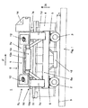
図1は、全部で4つのゴムタイヤ付き車輪2を介して地面3を走行することのできるストラドルキャリア装置1の概略側面図を示す。車輪2は従来通り、仮想的長方形の角に配置される。技術上の理由から必要な場合には、5つ以上のゴムタイヤ付き車輪2を設けることも基本的に可能である。しかし、これは結果的にストラドルキャリア装置1の全体としての複雑さの増大を伴うことになり、したがって駆動および操舵の部分により複雑な技術を使用しなければならない。自動誘導ストラドルキャリア装置1の場合、操舵しなければならない車輪2の増加のため、ナビゲーションもまた複雑になる。
FIG. 1 shows a schematic side view of a
ストラドルキャリア装置1の車輪2は、図示しない電動走行駆動装置および電動操舵モータを有する車輪装着走行機構5の構成部品である。設けられた個別車輪操舵は、適切な制御により、例えば最適化されたアッカーマン操舵または後退移動のような様々な操舵プログラムを実行することが可能であることを意味する。全部で4つの車輪装着走行機構5のうち、ストラドルキャリア装置1の走行方向Fに見て互いに前後に間隔を置いた配置された2つが、各々の長手方向の延びをストラドルキャリア装置1の走行方向Fに向けられて成る右側走行機構ガーダ6aおよび右側ガーダによって隠蔽されている左側走行機構ガーダに、それぞれ取り付けられる。互いに隣接してかつ互いに間隔を置いて平行に配置された2つの走行機構ガーダ6aは、前部ガントリフレーム7aを介して前部を、かつ後部ガントリフレーム7bを介して後部を互いに連結される。2つのU字状ガントリフレーム7aおよび7bの各々は、走行方向Fを横切る方向に向けられた水平上部ガントリガーダ7cから構成され、その側方端部は垂直ガントリ支持体7dによって各々接合される。前部および後部ガントリフレーム7a、7bは、走行方向Fに向けられた長手方向ガーダ8を介して互いに連結される。
The
2つのガントリガーダ7cおよび長手方向ガーダ8は上部フレーム9を形成しており、地面3からISOコンテナ4を荷取りしかつそれらを地面3に降ろすことができるように、当該上部フレーム9には昇降装置10が吊設される。この目的のために必要な昇降高さhは約150から300mmである。昇降装置10は、ケーブルまたは昇降機構10aを介して荷取り手段11に連結される、図示しない1つまたは複数の電動昇降駆動装置を含む。荷取り手段11は、ISOコンテナ4を荷役することができるようにするために、いわゆるスプレッダフレームとして設計される。スプレッダフレームは、いわゆるシングルリフトまたはツインリフトスプレッダとして設計される。すなわち、ツインリフトバージョンでは、ストラドルキャリア装置1の走行方向Fに見て前後に、2つの20フィートISOコンテナ4を荷取りすることができる。従来通り、荷取り手段11は、上部フレーム9の下で、かつ前部ガントリフレーム7aのガントリ支持体7dと後部ガントリフレーム7bのガントリ支持体7dとの間で、基本的に垂直昇降方向Hに昇降することができる。
The two gun triggers 7c and the longitudinal girder 8 form an upper frame 9 that lifts and lowers the upper frame 9 so that the ISO container 4 can be unloaded from the
さらに、上部フレーム9の領域では、スイッチキャビネット12および1つまたは複数の電池13を収容するために充分な空間が利用可能である。重量物輸送車両の高レベルの信頼性は、電池13を鉛酸蓄電池とすることによって達成される。鉛酸蓄電池は車両で長年使用されてきた。電池の重量は、約6から10tの範囲であり、好ましくは8から9tである。さらに、空になった電池13を充電済みの電池13と交換することができ、かつ適切な装置によって、上部フレーム9から外に、またはこの上部フレーム内に、走行方向Fを横切る方向に水平に移動させることができるように構成される。したがって電池13の充電プロセスは、ストラドルキャリア装置1の外で行なわれ、ストラドルキャリア装置1は電池の交換直後に利用可能である。交換プロセスは手動、半自動、または全自動で実行することができる。
Furthermore, in the area of the upper frame 9, sufficient space is available to accommodate the
また、代替的実施形態では、交換可能な電池13を、走行方向Fに見て前部ガントリフレーム7aのガントリ支持体7dと下部ガントリフレーム7bのガントリ支持体7dとの間に、かつ車輪装着走行機構5の高さに配置することも可能である。重量分散の理由から、走行方向Fに見て、移送されるISOコンテナ4の右隣および左隣に2つの電池13が設けられる。電池13はまた走行機構ガーダにも吊設され、そのうちの右側走行機構ガーダ6aだけが図示されている。このため、走行機構ガーダはその下側をさらに陥凹させることもできる。
Further, in an alternative embodiment, the
今後数年間に、例えばリチウムイオン電池のような他の種類の電池が鉛酸蓄電池と同等レベルの信頼性を達成した場合、それを使用することも可能であろう。 In the coming years, if other types of batteries, such as lithium ion batteries, achieve the same level of reliability as lead acid batteries, it could be used.
全体として、ストラドルキャリア装置1は、特に昇降装置10の昇降高さは、いわゆる平積み装置として設計される。すなわち、ストラドルキャリア装置1によって、単一のISOコンテナ4を地面3から荷取りし、かつ降ろすことができる。ISOコンテナ4の段積みはできない。適切に設計された荷取り手段11(ツインリフト)により、走行方向Fに見て前後に配置されかつ各々20フィートの長さを有する2つのISOコンテナ4を、一緒に荷取りすることが当然可能である。平積み装置としてのこの実施形態では、ストラドルキャリア装置1は重心が低くなり、優れたレベルの安定性が得られ、かつ構造を極めて小型化することができる。電動昇降駆動装置の性能に対する要求も緩和される。さらに、構造の高さは低く、したがって軽量化され、それは荷受けが4輪で足りることを意味する。
As a whole, the
さらに、ストラドルキャリア装置1は運転者が手動で制御するか、あるいは自動的に誘導することができる。手動バージョンの場合、前部ガントリフレーム7aの領域に運転室14が取り付けられる。自動誘導バージョンの場合、センサ15のための充分な空間が、それぞれ走行機構ガーダ6aの下および前後車輪装着走行機構5の間の領域に設けられ、センサは使用するナビゲーションシステムに応じて設計される。地面3に埋め込まれたトランスポンダを使用する場合、センサ15はアンテナとして設計される。
Furthermore, the
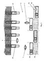
図2は、ストラドルキャリア装置1の第2実施形態の概略側面図を示す。このストラドルキャリア装置1は基本的に、上述したストラドルキャリア装置1と一致する。すなわち、前記説明の内容全体を援用する。参照番号も図1と同じ番号が使用されている。
FIG. 2 shows a schematic side view of the second embodiment of the
この第2実施形態では、電池13またはその受容フレーム13aが、ストラドルキャリア装置1の動作中に上部フレーム9に充分な頑健性をもたらす支持構成部品として設計される。この目的のために、電池13はさらに、ストラドルキャリア装置1に挿置された後で、例えばボルトによって固定される。電池13はまた、前後ガントリフレーム7a、7bの間でストラドルキャリア装置1の動作の結果生じる力を吸収することができるようにするために、適切に構成された電池フレーム13aをも有する。電池13の交換に関連して、上部フレーム9は電池13無しでは弱体化するが、上部フレーム9は、ストラドルキャリア装置1が新しい充電済み電池13を待っている間、充分な頑健性を有する。
In this second embodiment, the
自動誘導バージョンの場合、それぞれ走行機構ガーダ6aの下および前後車輪装着走行機構5の間の領域に、使用されるナビゲーションシステムの種類に応じて設計されるセンサ15のための充分な空間がある。地面3に埋め込まれたトランスポンダを使用する場合、センサ15はアンテナとして設計される。自動誘導バージョンに関連して、荷取りされるコンテナ4のための全自動物体認識を行うこともできる。埠頭16におけるコンテナ4の位置はおおよそ分かるので、ストラドルキャリア装置1はそこまで独立して進むことができる。最終位置に到達する前に、コンテナ4上を物体認識センサ構成が通過し、それによって得られた位置データからストラドルキャリア装置1を精緻に位置決めすることができる。次いでコンテナ4が荷取りされる。
In the case of the automatic guidance version, there is sufficient space for
この構成は、走行機構ガーダ6aの領域における電池13の構成にも適している。
This configuration is also suitable for the configuration of the
図3は、図1または図2に示した上記のストラドルキャリア装置1を用いた港湾レイアウトの平面図を示す。地面3は埠頭16の構成部分であり、ISOコンテナ4は当該地面の上を、多数のストラドルキャリア装置1を用いて、複数のコンテナクレーンブリッジ17と埠頭16に隣接するコンテナ段積みエリア18との間でコンテナ段積みクレーン19によって移動される。コンテナ荷役クレーンブリッジの代わりに、特に小規模の荷役港湾の場合、例えば移動港湾クレーンのような他の荷役装置を使用することも当然可能である。
FIG. 3 shows a plan view of a harbor layout using the above-described
さらに、操舵または昇降のような特定の駆動機能のために、純粋な電気駆動装置の代わりに、歯車に作動する電気油圧式駆動装置を使用するように構成することができ、あるいは技術的に必要になることがある。また、ISOコンテナ4が下降されるとき、またはストラドルキャリア装置1が制動されるときに、ストラドルキャリア装置1でエネルギを回収することも可能である。回収されたエネルギは次いで、いわゆるウルトラキャップまたはスーパキャップのような短期エネルギ貯蔵装置に貯蔵される。
In addition, for certain drive functions such as steering or lifting, it can be configured to use gear-actuated electro-hydraulic drives instead of pure electric drives or is technically necessary May be. It is also possible for the
1 ストラドルキャリア装置
2 車輪
3 地面
4 ISOコンテナ
5 車輪装着走行機構
6a 右側走行機構ガーダ
7a 前部ガントリフレーム
7b 後部ガントリフレーム
7c 上部ガントリガーダ
7d ガントリ支持体
8 長手方向ガーダ
9 上部フレーム
10 昇降装置
10a 昇降機構
11 荷取り手段
12 スイッチキャビネット
13 電池
14 運転室
15 センサ
16 埠頭
17 コンテナブリッジクレーン
18 コンテナ段積みエリア
19 コンテナ段積みクレーン
F 走行方向
H 昇降方向
h 昇降高さ
DESCRIPTION OF
本発明は、電池を介して電力を供給される電気駆動装置を備え、かつ昇降することのできるISOコンテナ用の荷取り手段を備えた、ISOコンテナ用のストラドルキャリア装置に関する。
また、本発明は、電池を介して電力を供給される電気駆動装置を備え、かつ昇降することのできるISOコンテナ用の荷役手段を備えた、ISOコンテナ用のストラドルキャリア装置を操作する方法に関する。
The present invention relates to a straddle carrier device for an ISO container that includes an electric drive device that is supplied with electric power via a battery, and that includes an ISO container loading mechanism that can be moved up and down.
The present invention also relates to a method of operating a straddle carrier device for an ISO container that includes an electric drive device that is supplied with electric power via a battery and that has a cargo handling means for the ISO container that can be moved up and down.
さらに、ドイツ実用新案第202004018066U1号から、ディーゼル電気駆動装置によって駆動される、さらなるストラドルキャリア装置が公知である。従来、このストラドルキャリア装置もまた、上部フレームを介して互いに連結された前部および後部ガントリフレームを有する。ディーゼル電気駆動装置は、上部フレームの領域であってコンテナ用の荷取り手段の上に配置される。
国際特許出願WO2007/143841A1号には、ハイブリッド駆動装置を介して操作されるガントリクレーンが開示されている。このハイブリッド駆動装置は、内燃エンジンと、ガントリクレーン内に固定的に設置された電池とを含む。
欧州特許出願EP2354075A1号に開示されているガントリクレーンは、当該ガントリクレーン内に固定的に設置された2つの電池を介して操作される。電池は電源供給システムを介して非接触的に充電することができ、それによって、片方の電池がガントリクレーンの操作によって放電される間にも、もう片方の電池を充電することができるように構成されている。
電池が固定的に設置されるような、電池で操作されるストラドルキャリア装置は、日本国特開2008-156047号公報や米国特許文献US6155770Aによっても公知である。 さらに、欧州特許出願EP2281769A2号には、手動操作されるストラドルキャリア装置が開示されており、ドイツ国特許文献DE02008539B3には、全自動式のストラドルキャリア装置が開示されている。
Furthermore, a further straddle carrier device is known from German utility model 202004018066U1, which is driven by a diesel electric drive. Conventionally, this straddle carrier device also has a front and rear gantry frame connected to each other via an upper frame. The diesel electric drive is located in the region of the upper frame and above the loading means for the container.
International patent application WO2007 / 143841A1 discloses a gantry crane operated via a hybrid drive. The hybrid drive device includes an internal combustion engine and a battery fixedly installed in the gantry crane.
The gantry crane disclosed in European Patent Application EP2354075A1 is operated via two batteries fixedly installed in the gantry crane. The battery can be charged contactlessly via the power supply system, so that one battery can be charged while the other battery is discharged by operation of the gantry crane Has been.
A battery-operated straddle carrier device in which the battery is fixedly installed is also known from Japanese Patent Laid-Open No. 2008-156047 and US Pat. No. 6,155,770A. Furthermore, European patent application EP2281769A2 discloses a manually operated straddle carrier device, and German patent document DE02008539B3 discloses a fully automatic straddle carrier device.
この先行技術に基づいて、本発明の目的は、改善された全電動ストラドルキャリア装置を作成することである。この目的は、請求項1の特徴を持つストラドルキャリア装置および請求項12の特徴を持つストラドルキャリア装置を操作する方法によって達成される。請求項2ないし請求項11および請求項13は、ストラドルキャリア装置の有利な実施形態を記載する。
Based on this prior art, the object of the present invention is to create an improved all-electric straddle carrier device. This object is achieved by a straddle carrier device having the features of
本発明によって、電池を介して電力を供給される電気駆動装置を備え、かつ昇降することのできる荷取り手段を備えた、ISOコンテナ用の改善されたストラドルキャリア装置が達成されるのは、ストラドルキャリア装置の外で電池を充電するために、電池が係脱可能にストラドルキャリア装置に接続され、充電プロセスと関連して交換することができるためである。この電池は交換可能にストラドルキャリア装置に接続されることが有利である。したがって、交換不能な電池の場合のように充電プロセスのためにストラドルキャリア装置の利用可能状態を制限することなく、充電する必要のある電池を充電済みの電池と交換することが特に簡単である。交換プロセスは、手動、半自動、または全自動で実行することができる。したがって電池の充電プロセスは、ストラドルキャリア装置の外で行なわれる。電動モータの形の電気駆動装置は、例えば走行駆動、制動駆動、操舵駆動、および昇降駆動のようなストラドルキャリア装置に設けられた駆動機能を果たすために、駆動される構成部品の歯車装置を介して、従来通りに作動する。例えば操舵駆動または昇降駆動のような特定の駆動機能の場合、電気油圧方式の操舵駆動または昇降駆動を設計するために、電気駆動装置を介して油圧ポンプを駆動することが必要になることがある。選択された電池式電気駆動装置は、ディーゼルエンジンの約2倍を超える有効度が達成されるという利点を有する。これは、電力消費レベルの低下、効率の向上、維持費の低下、特に騒音および排気ガスに関して高レベルの環境適合性をもたらす。 The present invention comprises an electric drive which is supplied with power via a battery, and with a load pickup means that can be raised and lowered for improved straddle carrier device for ISO containers is achieved, straddles This is because, in order to charge the battery outside the carrier device, the battery is detachably connected to the straddle carrier device and can be exchanged in connection with the charging process . This battery is advantageously connected to the straddle carrier device in a replaceable manner. Therefore, it is particularly easy to replace a battery that needs to be charged with a charged battery without limiting the availability of the straddle carrier device for the charging process as in the case of non-replaceable batteries. The exchange process can be performed manually, semi-automatically or fully automatically. Thus, the battery charging process takes place outside the straddle carrier device. An electric drive in the form of an electric motor is connected via a gear device which is driven to perform the drive functions provided in the straddle carrier device such as travel drive, brake drive, steering drive, and lift drive, for example. And operate as usual. For certain drive functions, such as steering drive or lift drive, it may be necessary to drive the hydraulic pump via an electric drive to design an electrohydraulic steering drive or lift drive. . The battery-operated electric drive selected has the advantage that an effectiveness that is more than about twice that of a diesel engine is achieved. This results in a lower level of power consumption, improved efficiency, lower maintenance costs, especially a high level of environmental compatibility with respect to noise and exhaust gases.
代替的に、ストラドルキャリア装置には運転室が配置され、ストラドルキャリア装置は手動で駆動することができる。
電池を介して電力を供給される電気駆動装置を備え、かつISOコンテナ用の昇降することのできる荷取り手段を備えたISOコンテナ用のストラドルキャリア装置を操作する方法は、空になった電池を充電済みの電池と交換するという事実によって改良される。
当該方法は、交換のために、電池をストラドルキャリア装置の内外に水平にかつその走行方向を横切る方向に移動させるという事実によってさらに改良される。
Alternatively, the cab is arranged in the straddle carrier device and the straddle carrier device can be driven manually.
A method for operating a straddle carrier device for an ISO container having an electric drive device supplied with power via the battery and having a lifting means for lifting and lowering the ISO container can be obtained by operating an empty battery. Improved by the fact that it replaces a charged battery.
The method is further improved by the fact that, for replacement, the battery is moved horizontally in and out of the straddle carrier device in a direction transverse to its direction of travel.
Claims (11)
Applications Claiming Priority (5)
| Application Number | Priority Date | Filing Date | Title |
|---|---|---|---|
| DE102011001847.6 | 2011-04-06 | ||
| DE102011001847A DE102011001847A1 (en) | 2011-04-06 | 2011-04-06 | Portal lifting device with electric drives |
| DE102011054209.4 | 2011-10-05 | ||
| DE102011054209A DE102011054209A1 (en) | 2011-10-05 | 2011-10-05 | Portal lifting equipment i.e. straddle carrier, for lifting ISO container, has electric drives powered by battery and comprising load-receiving unit for containers, where battery is replaceable and provided above load-receiving unit |
| PCT/EP2012/056094 WO2012136667A1 (en) | 2011-04-06 | 2012-04-03 | Straddle carrier device comprising electric drives |
Publications (1)
| Publication Number | Publication Date |
|---|---|
| JP2014509999A true JP2014509999A (en) | 2014-04-24 |
Family
ID=45976325
Family Applications (1)
| Application Number | Title | Priority Date | Filing Date |
|---|---|---|---|
| JP2014503118A Pending JP2014509999A (en) | 2011-04-06 | 2012-04-03 | Straddle carrier device with electric drive |
Country Status (8)
| Country | Link |
|---|---|
| US (1) | US20140017045A1 (en) |
| EP (1) | EP2694424B1 (en) |
| JP (1) | JP2014509999A (en) |
| KR (1) | KR20140022792A (en) |
| DK (1) | DK2694424T3 (en) |
| ES (1) | ES2547606T3 (en) |
| SG (1) | SG192630A1 (en) |
| WO (1) | WO2012136667A1 (en) |
Families Citing this family (10)
| Publication number | Priority date | Publication date | Assignee | Title |
|---|---|---|---|---|
| DE102015119193A1 (en) | 2015-11-07 | 2017-05-11 | Terex MHPS IP Management GmbH | Battery module for a traction drive and transport vehicle hereby |
| DE102015121804B4 (en) | 2015-12-15 | 2017-07-27 | Terex Mhps Gmbh | Transport vehicle for containers |
| DE102015121846B4 (en) | 2015-12-15 | 2017-07-27 | Terex Mhps Gmbh | Transport vehicle for containers |
| DE102016111450A1 (en) | 2016-06-22 | 2017-12-28 | Terex Mhps Gmbh | System for transporting containers, in particular ISO containers, by means of heavy-duty vehicles |
| DE102016111447A1 (en) | 2016-06-22 | 2017-12-28 | Terex Mhps Gmbh | System for transporting containers, in particular ISO containers, by means of heavy-duty vehicles |
| DE102017103032A1 (en) | 2017-02-15 | 2018-08-16 | Konecranes Global Corporation | POWER STATION FOR A CONTAINER TRANSPORT VEHICLE, CONTAINER TRANSPORT VEHICLE AND SYSTEM HEREUNDER |
| DE102017103097A1 (en) | 2017-02-15 | 2018-08-16 | Konecranes Global Corporation | Automatically guided transport vehicle for containers and method for operating the same and system with an automatically guided transport vehicle |
| RU189741U1 (en) * | 2017-11-03 | 2019-05-31 | ФЕДЕРАЛЬНОЕ ГОСУДАРСТВЕННОЕ БЮДЖЕТНОЕ ОБРАЗОВАТЕЛЬНОЕ УЧРЕЖДЕНИЕ ВЫСШЕГО ОБРАЗОВАНИЯ "Брянский государственный технический университет" | CARGO SUPPORT CART WITH LINEAR ELECTRIC MOTOR |
| FI127956B (en) * | 2018-01-17 | 2019-06-14 | Cargotec Finland Oy | Service platform, container handling carrier and method |
| US11338866B2 (en) * | 2018-05-31 | 2022-05-24 | Uatc, Llc | Movable front shield for vehicles |
Citations (5)
| Publication number | Priority date | Publication date | Assignee | Title |
|---|---|---|---|---|
| JPH03118940U (en) * | 1990-03-16 | 1991-12-09 | ||
| JP2000264578A (en) * | 1999-03-16 | 2000-09-26 | Taihei Dengyo Kaisha Ltd | Power supplying device for mobile crane device |
| JP2007267504A (en) * | 2006-03-28 | 2007-10-11 | Mitsubishi Heavy Ind Ltd | Storage apparatus of crane, crane power supply and power supply facility of crane |
| WO2010142688A1 (en) * | 2009-06-10 | 2010-12-16 | Gottwald Port Technology Gmbh | System for replacing a battery of a ground transportation vehicle, particularly of an unmanned heavy-duty transportation vehicle for iso containers |
| US20110155487A1 (en) * | 2008-06-13 | 2011-06-30 | Cargotec Finland Oy | Electrically driven straddle carrier, terminal tractor or corresponding |
Family Cites Families (26)
| Publication number | Priority date | Publication date | Assignee | Title |
|---|---|---|---|---|
| US3703243A (en) * | 1970-09-15 | 1972-11-21 | John Thomas Monk | Straddle carrier |
| US4284159A (en) * | 1979-04-26 | 1981-08-18 | Renner Manufacturing | Mobile crane |
| US4551059A (en) * | 1983-11-02 | 1985-11-05 | The United States Of America As Represented By The Secretary Of The Navy | Multi-directional straddle-lift carrier |
| US5711648A (en) * | 1994-01-06 | 1998-01-27 | Unlimited Range Electric Car Systems Company | Battery charging and transfer system |
| US5927938A (en) * | 1994-01-06 | 1999-07-27 | Unlimited Range Electric Car Systems Company | Battery charging and transfer system for electrically powered vehicles |
| US5760569A (en) * | 1997-02-26 | 1998-06-02 | Chase, Jr.; Robert B. | Replaceable battery module for electric vehicle |
| US5998963A (en) * | 1998-06-11 | 1999-12-07 | Aarseth; Einar | Electric vehicle service center and method for exchanging and charging vehicle batteries |
| US6155770A (en) * | 1998-07-01 | 2000-12-05 | Pods, Inc. | Apparatus for lifting, handling and transporting a container |
| US6998617B2 (en) * | 2003-06-11 | 2006-02-14 | Cargo Sentry, Inc. | Apparatus and method for detecting weapons of mass destruction |
| DE202004018066U1 (en) | 2004-11-20 | 2005-02-03 | Noell Mobile Systems & Cranes Gmbh | Straddle lift stacker for containers has two cable winches on both sides of lifting gear drive motor and with cable fastening on each side, and operating brakes installed between drive motor and cable winches |
| US7602143B2 (en) * | 2005-11-04 | 2009-10-13 | Peter David Capizzo | System for replenishing energy sources onboard different types of automotive vehicles |
| US7554278B2 (en) * | 2006-06-13 | 2009-06-30 | Railpower Technologies Corp. | Load-lifting apparatus and method of storing energy for the same |
| DE102006055749A1 (en) * | 2006-11-25 | 2008-05-29 | Noell Mobile Systems Gmbh | Portal lift truck with a low-emission and low-maintenance turbine drive |
| JP5207624B2 (en) * | 2006-12-22 | 2013-06-12 | 株式会社タダノエンジニアリング | Self-propelled lifter device |
| US20090058355A1 (en) * | 2007-08-29 | 2009-03-05 | Meyer Keith M | Electric vehicle battery module and replacement system |
| DE102008011539B3 (en) * | 2008-02-28 | 2009-06-18 | Noell Mobile Systems Gmbh | Fully automatic straddle carrier with local radiolocation and laser steering |
| FI121922B (en) * | 2009-08-05 | 2011-06-15 | Cargotec Finland Oy | Cab for straddle carrier |
| WO2011053681A1 (en) * | 2009-10-30 | 2011-05-05 | Comau, Inc. | Final assembly machine and method of use |
| JP2013515645A (en) * | 2009-12-23 | 2013-05-09 | プロテラ インコーポレイテッド | Charging station for electric vehicles |
| JP2011162287A (en) * | 2010-02-08 | 2011-08-25 | Mitsubishi Heavy Ind Ltd | Power feeding device and tire type gantry crane including the same |
| FR2972143B1 (en) * | 2011-03-01 | 2013-09-20 | Renault Sa | SYSTEM FOR CONNECTING A POWER BATTERY TO A MOTOR VEHICLE |
| DE102011001847A1 (en) * | 2011-04-06 | 2012-10-11 | Gottwald Port Technology Gmbh | Portal lifting device with electric drives |
| KR101245566B1 (en) * | 2012-01-31 | 2013-03-22 | 한국항공대학교산학협력단 | Electric bus and electric bus battery exchanging system |
| US8694155B2 (en) * | 2012-06-26 | 2014-04-08 | Motex Products Co., Ltd. | System for auto-exchanging of electric vehicle battery |
| US9156360B2 (en) * | 2012-07-01 | 2015-10-13 | Kookmin University Industry Academy Cooperation Foundation | Battery exchanging-type charging station system for electric vehicle |
| US8973254B2 (en) * | 2013-03-07 | 2015-03-10 | Jasper Ev Tech, Llc | System and method for rapid battery exchange in electric vehicles |
-
2012
- 2012-04-03 US US14/007,877 patent/US20140017045A1/en not_active Abandoned
- 2012-04-03 ES ES12715020.9T patent/ES2547606T3/en active Active
- 2012-04-03 WO PCT/EP2012/056094 patent/WO2012136667A1/en active Application Filing
- 2012-04-03 DK DK12715020.9T patent/DK2694424T3/en active
- 2012-04-03 JP JP2014503118A patent/JP2014509999A/en active Pending
- 2012-04-03 SG SG2013059597A patent/SG192630A1/en unknown
- 2012-04-03 EP EP12715020.9A patent/EP2694424B1/en not_active Not-in-force
- 2012-04-03 KR KR1020137019691A patent/KR20140022792A/en not_active Application Discontinuation
Patent Citations (6)
| Publication number | Priority date | Publication date | Assignee | Title |
|---|---|---|---|---|
| JPH03118940U (en) * | 1990-03-16 | 1991-12-09 | ||
| JP2000264578A (en) * | 1999-03-16 | 2000-09-26 | Taihei Dengyo Kaisha Ltd | Power supplying device for mobile crane device |
| JP2007267504A (en) * | 2006-03-28 | 2007-10-11 | Mitsubishi Heavy Ind Ltd | Storage apparatus of crane, crane power supply and power supply facility of crane |
| US20110155487A1 (en) * | 2008-06-13 | 2011-06-30 | Cargotec Finland Oy | Electrically driven straddle carrier, terminal tractor or corresponding |
| WO2010142688A1 (en) * | 2009-06-10 | 2010-12-16 | Gottwald Port Technology Gmbh | System for replacing a battery of a ground transportation vehicle, particularly of an unmanned heavy-duty transportation vehicle for iso containers |
| JP2012529408A (en) * | 2009-06-10 | 2012-11-22 | ゴットヴァルト ポート テクノロジー ゲーエムベーハー | System for replacing batteries of ground transport vehicles, especially self-driving large transport vehicles for ISO containers |
Also Published As
| Publication number | Publication date |
|---|---|
| EP2694424A1 (en) | 2014-02-12 |
| US20140017045A1 (en) | 2014-01-16 |
| KR20140022792A (en) | 2014-02-25 |
| ES2547606T3 (en) | 2015-10-07 |
| EP2694424B1 (en) | 2015-06-17 |
| WO2012136667A1 (en) | 2012-10-11 |
| SG192630A1 (en) | 2013-09-30 |
| DK2694424T3 (en) | 2015-09-07 |
Similar Documents
| Publication | Publication Date | Title |
|---|---|---|
| JP6082998B2 (en) | Straddle carrier device with electric drive | |
| JP2014509999A (en) | Straddle carrier device with electric drive | |
| US7731041B2 (en) | Gantry stacker with two side-by-side spreaders | |
| NL2008775C2 (en) | Automated guided vehicle and assembly of an automated guided vehicle and a platform. | |
| CA2757417C (en) | Heavy-duty ground transport vehicle, in particular a heavy-duty automated guided vehicle for iso-containers | |
| ES2842978T3 (en) | Electric charging station for container transport vehicle, container transport vehicle and system with these | |
| US20110155487A1 (en) | Electrically driven straddle carrier, terminal tractor or corresponding | |
| US11414000B2 (en) | Self-leveling single axle dump truck | |
| CN104670349B (en) | It is a kind of can Self-loading-unloading goods semitrailer | |
| CN201842613U (en) | Accompanying type self-loading and self-unloading electric forklift | |
| CN103522932B (en) | Car transporter | |
| RU2526019C2 (en) | Gantry loader | |
| CN108367698B (en) | Transport vehicle for containers | |
| CN105883678A (en) | Multifunctional dual-layer forklift | |
| CN102730601A (en) | Electric forklift truck | |
| CN202294447U (en) | Vehicle-mounted loading/unloading platform | |
| CN202782842U (en) | Chassis structure of special all-wheel drive vehicle for transporting pontoon bridge | |
| CN216272963U (en) | Balanced AGV heavy stacking vehicle body with brand new structure | |
| CN203450012U (en) | Vehicle carrying device of vehicle transporting vehicle |
Legal Events
| Date | Code | Title | Description |
|---|---|---|---|
| A529 | Written submission of copy of amendment under section 34 (pct) |
Free format text: JAPANESE INTERMEDIATE CODE: A529 Effective date: 20131121 |
|
| A711 | Notification of change in applicant |
Free format text: JAPANESE INTERMEDIATE CODE: A712 Effective date: 20141106 |
|
| A521 | Written amendment |
Free format text: JAPANESE INTERMEDIATE CODE: A523 Effective date: 20150212 |
|
| A621 | Written request for application examination |
Free format text: JAPANESE INTERMEDIATE CODE: A621 Effective date: 20150325 |
|
| A977 | Report on retrieval |
Free format text: JAPANESE INTERMEDIATE CODE: A971007 Effective date: 20160225 |
|
| A131 | Notification of reasons for refusal |
Free format text: JAPANESE INTERMEDIATE CODE: A131 Effective date: 20160315 |
|
| A521 | Written amendment |
Free format text: JAPANESE INTERMEDIATE CODE: A523 Effective date: 20160614 |
|
| A711 | Notification of change in applicant |
Free format text: JAPANESE INTERMEDIATE CODE: A711 Effective date: 20160620 |
|
| A131 | Notification of reasons for refusal |
Free format text: JAPANESE INTERMEDIATE CODE: A131 Effective date: 20161129 |
|
| A02 | Decision of refusal |
Free format text: JAPANESE INTERMEDIATE CODE: A02 Effective date: 20170725 |