JP2014236185A - Apparatus and method for transferring solar battery cell - Google Patents
Apparatus and method for transferring solar battery cell Download PDFInfo
- Publication number
- JP2014236185A JP2014236185A JP2013118838A JP2013118838A JP2014236185A JP 2014236185 A JP2014236185 A JP 2014236185A JP 2013118838 A JP2013118838 A JP 2013118838A JP 2013118838 A JP2013118838 A JP 2013118838A JP 2014236185 A JP2014236185 A JP 2014236185A
- Authority
- JP
- Japan
- Prior art keywords
- index
- rotation angle
- angle position
- solar cell
- index table
- Prior art date
- Legal status (The legal status is an assumption and is not a legal conclusion. Google has not performed a legal analysis and makes no representation as to the accuracy of the status listed.)
- Pending
Links
- 238000000034 method Methods 0.000 title claims abstract description 22
- 238000005259 measurement Methods 0.000 claims abstract description 59
- 238000012545 processing Methods 0.000 claims abstract description 13
- 238000012546 transfer Methods 0.000 claims description 45
- 230000007246 mechanism Effects 0.000 claims description 42
- 230000008569 process Effects 0.000 claims description 13
- 238000001179 sorption measurement Methods 0.000 claims description 13
- 239000000523 sample Substances 0.000 claims description 9
- 230000001360 synchronised effect Effects 0.000 claims description 4
- 239000012530 fluid Substances 0.000 claims description 3
- 230000001678 irradiating effect Effects 0.000 claims 1
- 230000009467 reduction Effects 0.000 abstract description 2
- 238000007689 inspection Methods 0.000 description 18
- XLYOFNOQVPJJNP-UHFFFAOYSA-N water Substances O XLYOFNOQVPJJNP-UHFFFAOYSA-N 0.000 description 8
- 230000002950 deficient Effects 0.000 description 5
- 238000004519 manufacturing process Methods 0.000 description 4
- 238000005286 illumination Methods 0.000 description 3
- 238000003825 pressing Methods 0.000 description 3
- 230000003247 decreasing effect Effects 0.000 description 2
- 239000003507 refrigerant Substances 0.000 description 2
- 238000004904 shortening Methods 0.000 description 2
- XUIMIQQOPSSXEZ-UHFFFAOYSA-N Silicon Chemical compound [Si] XUIMIQQOPSSXEZ-UHFFFAOYSA-N 0.000 description 1
- 230000005856 abnormality Effects 0.000 description 1
- 239000002826 coolant Substances 0.000 description 1
- 238000005336 cracking Methods 0.000 description 1
- 239000013078 crystal Substances 0.000 description 1
- 230000000694 effects Effects 0.000 description 1
- 230000020169 heat generation Effects 0.000 description 1
- 230000006872 improvement Effects 0.000 description 1
- 238000011068 loading method Methods 0.000 description 1
- 239000000463 material Substances 0.000 description 1
- 238000012986 modification Methods 0.000 description 1
- 230000004048 modification Effects 0.000 description 1
- 238000010248 power generation Methods 0.000 description 1
- 230000000630 rising effect Effects 0.000 description 1
- 229910052710 silicon Inorganic materials 0.000 description 1
- 239000010703 silicon Substances 0.000 description 1
- 239000000758 substrate Substances 0.000 description 1
Images


Classifications
-
- H—ELECTRICITY
- H01—ELECTRIC ELEMENTS
- H01L—SEMICONDUCTOR DEVICES NOT COVERED BY CLASS H10
- H01L21/00—Processes or apparatus adapted for the manufacture or treatment of semiconductor or solid state devices or of parts thereof
- H01L21/67—Apparatus specially adapted for handling semiconductor or electric solid state devices during manufacture or treatment thereof; Apparatus specially adapted for handling wafers during manufacture or treatment of semiconductor or electric solid state devices or components ; Apparatus not specifically provided for elsewhere
- H01L21/677—Apparatus specially adapted for handling semiconductor or electric solid state devices during manufacture or treatment thereof; Apparatus specially adapted for handling wafers during manufacture or treatment of semiconductor or electric solid state devices or components ; Apparatus not specifically provided for elsewhere for conveying, e.g. between different workstations
- H01L21/67763—Apparatus specially adapted for handling semiconductor or electric solid state devices during manufacture or treatment thereof; Apparatus specially adapted for handling wafers during manufacture or treatment of semiconductor or electric solid state devices or components ; Apparatus not specifically provided for elsewhere for conveying, e.g. between different workstations the wafers being stored in a carrier, involving loading and unloading
-
- H—ELECTRICITY
- H01—ELECTRIC ELEMENTS
- H01L—SEMICONDUCTOR DEVICES NOT COVERED BY CLASS H10
- H01L31/00—Semiconductor devices sensitive to infrared radiation, light, electromagnetic radiation of shorter wavelength or corpuscular radiation and specially adapted either for the conversion of the energy of such radiation into electrical energy or for the control of electrical energy by such radiation; Processes or apparatus specially adapted for the manufacture or treatment thereof or of parts thereof; Details thereof
- H01L31/04—Semiconductor devices sensitive to infrared radiation, light, electromagnetic radiation of shorter wavelength or corpuscular radiation and specially adapted either for the conversion of the energy of such radiation into electrical energy or for the control of electrical energy by such radiation; Processes or apparatus specially adapted for the manufacture or treatment thereof or of parts thereof; Details thereof adapted as photovoltaic [PV] conversion devices
- H01L31/06—Semiconductor devices sensitive to infrared radiation, light, electromagnetic radiation of shorter wavelength or corpuscular radiation and specially adapted either for the conversion of the energy of such radiation into electrical energy or for the control of electrical energy by such radiation; Processes or apparatus specially adapted for the manufacture or treatment thereof or of parts thereof; Details thereof adapted as photovoltaic [PV] conversion devices characterised by at least one potential-jump barrier or surface barrier
- H01L31/068—Semiconductor devices sensitive to infrared radiation, light, electromagnetic radiation of shorter wavelength or corpuscular radiation and specially adapted either for the conversion of the energy of such radiation into electrical energy or for the control of electrical energy by such radiation; Processes or apparatus specially adapted for the manufacture or treatment thereof or of parts thereof; Details thereof adapted as photovoltaic [PV] conversion devices characterised by at least one potential-jump barrier or surface barrier the potential barriers being only of the PN homojunction type, e.g. bulk silicon PN homojunction solar cells or thin film polycrystalline silicon PN homojunction solar cells
- H01L31/0682—Semiconductor devices sensitive to infrared radiation, light, electromagnetic radiation of shorter wavelength or corpuscular radiation and specially adapted either for the conversion of the energy of such radiation into electrical energy or for the control of electrical energy by such radiation; Processes or apparatus specially adapted for the manufacture or treatment thereof or of parts thereof; Details thereof adapted as photovoltaic [PV] conversion devices characterised by at least one potential-jump barrier or surface barrier the potential barriers being only of the PN homojunction type, e.g. bulk silicon PN homojunction solar cells or thin film polycrystalline silicon PN homojunction solar cells back-junction, i.e. rearside emitter, solar cells, e.g. interdigitated base-emitter regions back-junction cells
-
- H—ELECTRICITY
- H01—ELECTRIC ELEMENTS
- H01L—SEMICONDUCTOR DEVICES NOT COVERED BY CLASS H10
- H01L31/00—Semiconductor devices sensitive to infrared radiation, light, electromagnetic radiation of shorter wavelength or corpuscular radiation and specially adapted either for the conversion of the energy of such radiation into electrical energy or for the control of electrical energy by such radiation; Processes or apparatus specially adapted for the manufacture or treatment thereof or of parts thereof; Details thereof
- H01L31/18—Processes or apparatus specially adapted for the manufacture or treatment of these devices or of parts thereof
- H01L31/1876—Particular processes or apparatus for batch treatment of the devices
-
- Y—GENERAL TAGGING OF NEW TECHNOLOGICAL DEVELOPMENTS; GENERAL TAGGING OF CROSS-SECTIONAL TECHNOLOGIES SPANNING OVER SEVERAL SECTIONS OF THE IPC; TECHNICAL SUBJECTS COVERED BY FORMER USPC CROSS-REFERENCE ART COLLECTIONS [XRACs] AND DIGESTS
- Y02—TECHNOLOGIES OR APPLICATIONS FOR MITIGATION OR ADAPTATION AGAINST CLIMATE CHANGE
- Y02E—REDUCTION OF GREENHOUSE GAS [GHG] EMISSIONS, RELATED TO ENERGY GENERATION, TRANSMISSION OR DISTRIBUTION
- Y02E10/00—Energy generation through renewable energy sources
- Y02E10/50—Photovoltaic [PV] energy
- Y02E10/547—Monocrystalline silicon PV cells
-
- Y—GENERAL TAGGING OF NEW TECHNOLOGICAL DEVELOPMENTS; GENERAL TAGGING OF CROSS-SECTIONAL TECHNOLOGIES SPANNING OVER SEVERAL SECTIONS OF THE IPC; TECHNICAL SUBJECTS COVERED BY FORMER USPC CROSS-REFERENCE ART COLLECTIONS [XRACs] AND DIGESTS
- Y02—TECHNOLOGIES OR APPLICATIONS FOR MITIGATION OR ADAPTATION AGAINST CLIMATE CHANGE
- Y02P—CLIMATE CHANGE MITIGATION TECHNOLOGIES IN THE PRODUCTION OR PROCESSING OF GOODS
- Y02P70/00—Climate change mitigation technologies in the production process for final industrial or consumer products
- Y02P70/50—Manufacturing or production processes characterised by the final manufactured product
Abstract
Description
本発明は、太陽電池セルの移載装置及び移載方法に関するものである。 The present invention relates to a transfer device and transfer method for solar cells.
太陽電池の製造においては、太陽電池が予め設定された発電能力を有しているか否か出力特性を評価することが重要である。太陽電池の出力特性は、太陽電池セルの表面に基準となる擬似太陽光を照射した状態で負荷電源を調整し、各負荷量におけるそれぞれの出力電流値及び出力電圧値を測定点として計測する。この測定は、太陽電池セルの表面及び裏面に配されたフィンガー電極の集電極部に相当するバスバー電極部に接触させたプローブを用いて行う。収集された電流と電圧に関する測定値を、縦軸を電流、横軸を電圧とするグラフ上にプロットし、各プロット間を補間することにより太陽電池セルの特性曲線が得られる。この得られた曲線は、一般に電流電圧(I−V)特性曲線と称されている。 In the manufacture of solar cells, it is important to evaluate the output characteristics whether or not the solar cells have a preset power generation capability. The output characteristics of the solar battery are measured by adjusting the load power source in a state in which the reference solar light is irradiated on the surface of the solar battery cell, and measuring each output current value and output voltage value at each load amount as measurement points. This measurement is performed using a probe brought into contact with the bus bar electrode portion corresponding to the collector electrode portion of the finger electrode disposed on the front and back surfaces of the solar battery cell. The measured values related to the collected current and voltage are plotted on a graph with the vertical axis representing current and the horizontal axis representing voltage, and the characteristic curve of the solar cell is obtained by interpolating between the plots. This obtained curve is generally called a current-voltage (IV) characteristic curve.
ところで太陽電池には、材質や構造により種々の種類が存在する。現在主流となっている太陽電池は、シリコン結晶を用いたものである。そして、現在最も多く生産・販売されている太陽電池では、太陽光を受ける受光面にn電極、裏面にp電極がそれぞれ設けられている。しかし、このような太陽電池では、受光面の電極の下の基板には太陽光が入射しないため、その部分では発電しない。そこで、太陽光を100%取り込むことができる高効率な太陽電池として、受光面には電極が存在せず、裏面側にp電極及びn電極が形成された裏面電極型太陽電池が製造されている。 There are various types of solar cells depending on the material and structure. The solar cells that are currently mainstream use silicon crystals. And in the solar cell currently produced and sold most, an n electrode is provided on the light receiving surface that receives sunlight, and a p electrode is provided on the back surface. However, in such a solar cell, since sunlight does not enter the substrate under the electrode on the light receiving surface, power is not generated in that portion. Therefore, as a high-efficiency solar cell that can capture 100% of sunlight, a back electrode type solar cell in which no electrode is present on the light receiving surface and a p-electrode and an n-electrode are formed on the back surface is manufactured. .
しかし、このような裏面電極型太陽電池は、受光面にも電極が設けられた太陽電池に比べて製造プロセスがより複雑であり、製造コストを増加させると共に量産性を低下させている。また、上述した太陽電池セルの電流電圧の出力特性を評価する工程は、製造後の検査において重要な測定項目である。しかしながら、この検査工程が裏面電極型太陽電池ではより複雑であり、高コストであるさらなる要因の一つともなっている。 However, such a back electrode type solar cell has a more complicated manufacturing process than a solar cell in which an electrode is also provided on the light receiving surface, increasing the manufacturing cost and reducing the mass productivity. Moreover, the process of evaluating the output characteristics of the current voltage of the solar battery cell described above is an important measurement item in the inspection after manufacturing. However, this inspection process is more complicated in the back electrode type solar cell, and is one of the additional factors that are expensive.
検査工程において、太陽電池セルの移載を多く繰り返すと非効率である上に位置精度が低下して測定精度の低下を招く。また、移載を多く繰り返すと計測に至るまでに時間を要する。この結果、検査で照射される照明や周囲の各装置から発生した熱により太陽電池自体の温度上昇を招いて出力電圧が低下し、さらに測定精度の低下を招くこととなる。従って、出力特性の検査工程の簡素化及び検査時間短縮等の効率化によるコスト削減は、測定精度の向上と共に、裏面電極型太陽電池のような生産性が低く高コストの太陽電池においては特に重要である。 In the inspection process, if the transfer of the solar cells is repeated many times, it is inefficient and the position accuracy is lowered, leading to a decrease in measurement accuracy. Also, if the transfer is repeated many times, it takes time to measure. As a result, the temperature of the solar cell itself is increased by the illumination irradiated in the inspection and the heat generated from the surrounding devices, the output voltage is decreased, and the measurement accuracy is further decreased. Therefore, cost reduction by simplifying the inspection process for output characteristics and shortening the inspection time is particularly important for low-cost and high-cost solar cells such as back electrode solar cells as well as improving measurement accuracy. It is.
本発明は上記事情に鑑み、測定精度の向上と共に、出力特性の検査工程を簡素化し、測定に要する時間を短縮して効率化することによりコスト削減が可能な太陽電池セルの移載装置及び移載方法を提供することを目的とする。 In view of the above circumstances, the present invention provides a solar cell transfer device and a transfer device capable of reducing costs by improving the measurement accuracy, simplifying the output characteristic inspection process, and reducing the time required for measurement and improving efficiency. The purpose is to provide a loading method.
本発明の太陽電池セルの移載装置は、
第一の回転中心から放射状に延在するように設けられた複数の第一のインデックステーブルのそれぞれの上面側に太陽電池セルを載置して保持する太陽電池セル載置保持部を有する第一のインデックスと、
前記第一のインデックスを第一の方向に回転させる第一の駆動機構と、
第二の回転中心から放射状に延在するように設けられた複数の第二のインデックステーブルのそれぞれの下面側に太陽電池セルを吸着して保持する太陽電池セル吸着保持部を有する第二のインデックスと、
前記第二のインデックスを前記第一の方向又は第二の方向に回転させる第二の駆動機構と、
前記太陽電池セル載置保持部の動作と、前記太陽電池セル吸着保持部の動作と、前記第一の駆動機構の動作と、前記第二の駆動機構の動作とをそれぞれ制御する中央処理制御部と、
を備え、
前記中央処理制御部は、
前記第一のインデックステーブルの前記太陽電池セル載置保持部が順次第一の回転角度位置において太陽電池セルを受け取り載置して保持する動作と、
前記第一のインデックステーブルが順次前記第一の回転角度位置から回転して第二の回転角度位置に到達する動作と、
前記第二のインデックステーブルの前記太陽電池セル吸着保持部が順次前記第二の回転角度位置の上方に位置する第三の回転角度位置において、前記第二の回転角度位置にある前記第一のインデックステーブルから太陽電池セルを受け取り吸着して保持する動作と、
太陽電池セルの電流電圧特性の測定のために、前記第二のインデックステーブルが順次前記第三の回転角度位置から回転して第四の回転角度位置に到達する動作と、
太陽電池セルを後段の工程へ受け渡すために、前記第二のインデックステーブルが順次前記第四の回転角度位置から回転して第五の回転角度位置に到達する動作と、
が前記第一のインデックスと前記第二のインデックスの間で同期した回転角度毎に行われるように制御することを特徴とする。
The solar cell transfer device of the present invention is
A first solar cell mounting holder that holds and holds solar cells on the upper surface side of each of the plurality of first index tables provided to extend radially from the first rotation center. And the index of
A first drive mechanism for rotating the first index in a first direction;
A second index having a solar cell adsorption holding portion that adsorbs and holds solar cells on the lower surface side of each of the plurality of second index tables provided to extend radially from the second rotation center. When,
A second drive mechanism for rotating the second index in the first direction or the second direction;
Central processing control unit for controlling the operation of the solar cell placement holding unit, the operation of the solar cell adsorption holding unit, the operation of the first drive mechanism, and the operation of the second drive mechanism, respectively. When,
With
The central processing control unit
The operation of the solar cell placement and holding part of the first index table receiving and placing solar cells sequentially at the first rotation angle position, and
An operation in which the first index table sequentially rotates from the first rotation angle position to reach a second rotation angle position;
The first index at the second rotation angle position at the third rotation angle position where the solar cell suction holding portion of the second index table is sequentially positioned above the second rotation angle position. Receiving and adsorbing and holding solar cells from the table;
For the measurement of the current-voltage characteristics of the solar battery cell, the second index table sequentially rotates from the third rotation angle position to reach the fourth rotation angle position;
The second index table sequentially rotates from the fourth rotation angle position to reach the fifth rotation angle position in order to deliver the solar cell to the subsequent process;
Is controlled at every rotation angle synchronized between the first index and the second index.
また本発明の太陽電池セルの移載方法は、
放射状に延在するように設けられた複数の第一のインデックステーブルのそれぞれの上面側に太陽電池セルを載置して保持する太陽電池セル載置保持部を有する第一のインデックスを第一の駆動機構により第一の方向に回転させ、放射状に延在するように設けられた複数の第二のインデックステーブルのそれぞれの下面側に太陽電池セルを吸着して保持する太陽電池セル吸着保持部を有する第二のインデックスを第二の駆動機構により前記第一の方向又は第二の方向に回転させ、前記太陽電池セル載置保持部の動作と、前記太陽電池セル吸着保持部の動作と、前記第一の駆動機構の動作と、前記第二の駆動機構の動作とをそれぞれ制御する中央処理制御部とを備える載置装置を用いて、太陽電池セルの載置を行う方法であって、
前記中央処理制御部の制御により、
前記第一のインデックステーブルの前記太陽電池セル載置保持部が順次第一の回転角度位置において太陽電池セルを受け取り載置して保持する動作と、
前記第一のインデックステーブルが順次前記第一の回転角度位置から回転して第二の回転角度位置に到達する動作と、
前記第二のインデックステーブルの前記太陽電池セル吸着保持部が順次前記第二の回転角度位置の上方に位置する第三の回転角度位置において、前記第二の回転角度位置にある前記第一のインデックステーブルから太陽電池セルを受け取り吸着して保持する動作と、
太陽電池セルの電流電圧特性の測定のために、前記第二のインデックステーブルが順次前記第三の回転角度位置から回転して第四の回転角度位置に到達する動作と、
太陽電池セルを後段の工程へ受け渡すために、前記第二のインデックステーブルが順次前記第四の回転角度位置から回転して第五の回転角度位置に到達する動作と、
が前記第一のインデックスと前記第二のインデックスの間で同期した回転角度毎に行われることを特徴とする。
Moreover, the transfer method of the photovoltaic cell of the present invention is
A first index having a solar cell placement holding unit for placing and holding solar cells on each upper surface side of a plurality of first index tables provided to extend radially A solar cell adsorption holding unit that adsorbs and holds the solar cells on the lower surface side of each of the plurality of second index tables that are rotated in the first direction by the drive mechanism and extend radially. The second drive mechanism has a second drive mechanism to rotate in the first direction or the second direction, the operation of the solar cell placement holding unit, the operation of the solar cell adsorption holding unit, A method of placing solar cells using a placement device comprising a central processing control unit that controls the operation of the first drive mechanism and the operation of the second drive mechanism, respectively.
Under the control of the central processing control unit,
The operation of the solar cell placement and holding part of the first index table receiving and placing solar cells sequentially at the first rotation angle position, and
An operation in which the first index table sequentially rotates from the first rotation angle position to reach a second rotation angle position;
The first index at the second rotation angle position at the third rotation angle position where the solar cell suction holding portion of the second index table is sequentially positioned above the second rotation angle position. Receiving and adsorbing and holding solar cells from the table;
For the measurement of the current-voltage characteristics of the solar battery cell, the second index table sequentially rotates from the third rotation angle position to reach the fourth rotation angle position;
The second index table sequentially rotates from the fourth rotation angle position to reach the fifth rotation angle position in order to deliver the solar cell to the subsequent process;
Is performed for each rotation angle synchronized between the first index and the second index.
本発明の太陽電池セルの移載装置及び移載方法によれば、簡素な機構で高い位置精度が得られ、測定精度が向上すると共に、出力特性の検査工程が簡素化され測定に要する時間が短縮されて効率が向上することによりコスト削減が可能である。 According to the photovoltaic cell transfer device and transfer method of the present invention, high positional accuracy can be obtained with a simple mechanism, the measurement accuracy can be improved, the output characteristic inspection process can be simplified, and the time required for measurement can be improved. Costs can be reduced by shortening and improving efficiency.
以下、本発明の実施の形態による太陽電池セルの移載装置及び移載方法について図面を参照して説明する。 Hereinafter, a transfer device and a transfer method for solar cells according to embodiments of the present invention will be described with reference to the drawings.
図1の平面図に、本発明の一実施の形態による太陽電池セルの移載装置20を含む太陽電池セルの電流電圧特性測定装置1全体の概略的な構成を示す。
FIG. 1 is a plan view showing a schematic configuration of a solar cell current-voltage
この太陽電池セルの電流電圧特性測定装置1は、太陽電池セル12の外形検査を行った後、良品と判定したものを後段に供給するセル供給部10と、太陽電池セル12の電流電圧特性を測定するI−V測定部30と、セル供給部10から供給された太陽電池セル12をI−V測定部30に投入するため太陽電池セル12の移載を行う移載装置20と、I−V測定部30により測定された電流電圧特性の測定結果に基づいて太陽電池セル12を分別するセル分別部40と、セル供給部10、移載装置20、I−V測定部30、セル分別部40のそれぞれの動作を制御する中央処理制御部50とを備えている。
This solar cell current-voltage
セル供給部10は、搬送路11、セル移載ロボット13、セル検査部14及びリジェクト部15を有する。
The
図示されていない工程で別途製造された太陽電池セル12が、搬送路11により、所定の取り出し位置まで搬送される。この取り出し位置に到達した太陽電池セル12は、セル移載ロボット13により取り出され、先ずセル検査部14に載置される。
The
載置された太陽電池セル12は、セル検査部14により外形状態の検査が行われる。より具体的には、太陽電池セル12の上方から図示されていない光源により光が照射され、カメラにより太陽電池セル12の形状が撮影される。そして、太陽電池セル12の外形形状、バスバーの位置、各寸法の異常の有無、欠けや割れ等の有無に基づき良品か否かが判定される。
The placed
セル検査部14により良品と判定された太陽電池セル12は、セル移載ロボット13により、移載装置20へ移動される。一方、セル検査部14により不良と判定された太陽電池セル12は、セル移載ロボット13により、使用されない不良品を蓄積するリジェクト部15に送られて除去される。
The
移載装置20は、第一のインデックス21と、第二のインデックス22と、後述するように第一のインデックス21及び第二のインデックス22をそれぞれ駆動する駆動機構と、第一のインデックス21の温度を調整する温調機構とを有する。
The
第一のインデックス21は、図1に示されたように、本実施の形態では回転中心C1から90度毎に4個の第一のインデックステーブル23が放射状に延在する十字形状を有する。この第一のインデックステーブル23に、それぞれセル移載ロボット13によって太陽電池セル12が載置される。第一のインデックステーブル23の上面側には、それぞれ吸引口21aを有する太陽電池セル載置保持部が設けられており、図示されていない吸引装置により太陽電池セル12が吸引されて載置され保持される。第一のインデックス21は、所定の受取位置21bにおいて停止し、セル移載ロボット13から太陽電池セル12を受け取る。矢印R1の方向に270度回転し、所定の受渡位置21cにおいて停止し、第二のインデックス22に太陽電池セル12を受け渡す。
As shown in FIG. 1, the
第二のインデックス22も第一のインデックス21と同様に、回転中心C2から90度毎に4個の第二のインデックステーブル26が放射状に延在する十字形状を有する。それぞれの第二のインデックステーブル26は、所定の受取位置22aにおいて停止し、太陽電池セル12を第一のインデックス21から順次受け渡される。第二のインデックステーブル26の下面側には、それぞれ吸着パッド26bを有する太陽電池セル吸着保持部が設けられており、図示されていない吸引装置により太陽電池セル12が吸着され保持される。
Similarly to the
第二のインデックス22は受取位置22aから、第一のインデックス21と逆向きの矢印R2の方向に90度回転して停止し、所定の測定位置22bにおいて、I−V測定部30により太陽電池セル12の電流電圧特性の測定が行われる。
The
I−V測定部30は、I−V測定テーブル31と、図示されていないI−V測定装置とを有する。I−V測定装置は、図示されていない負荷電源、負荷制御部、電流計、電圧計、光源、光源制御部、及び測定動作全体の動作を制御する測定制御部を有する。
The
光源は第二のインデックス22の上方に配置され、この光源から照射された光が通過して裏面側に吸着された太陽電池セル12に照射できるように、第二のインデックス22には照射光通過口26aが形成されている。
The light source is disposed above the
負荷電源は被測定対象の太陽電池セル12に接続され、太陽電池セル12に負荷を与える。負荷電源の負荷量は負荷制御部により調整され、複数の負荷量を太陽電池セル12に与えることができる。これにより、太陽電池セル12から負荷電源の各負荷量に応じた出力電流と出力電圧とが生成され、電流計、電圧計により測定される。測定制御部により、電流計、電圧計の測定結果に基づいて太陽電池セル12のI−V特性曲線が生成される。
The load power source is connected to the
I−V測定部30で太陽電池セル12の電流電圧特性が測定された後、第二のインデックステーブル26は、測定位置22bから矢印R2の方向に90度回転して搬出位置22cで停止する。
After the current-voltage characteristic of the
セル分別部40は、搬送装置42、分別装置43を有する。搬送装置42に、搬出位置22cにある第二のインデックステーブル26から太陽電池セル12が受け渡され、分別装置43へ搬送される。分別装置43において、I−V測定部30における測定結果に基づいて等級分けの分別が行われて後段の工程へそれぞれ搬送される。
The
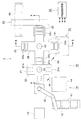
図2(a)に、図1に示された第一のインデックス21、第二のインデックス22を有する移載装置20を中心とする主要部のA−A線に沿う縦断面構造を示す。さらに、図2(b)に同主要部のB−B線に沿う縦断面構造を示す。
FIG. 2A shows a longitudinal cross-sectional structure along the AA line of the main part centering on the
第一のインデックス21では、回転中心C1から放射状に延在する4個の第一のインデックステーブル23が、駆動機構に相当するステップモータ24により90度単位で回転され、受取位置21b、受渡位置21cでそれぞれ停止する。
In the
第二のインデックス22も同様に、回転中心C2から放射状に延在する4個の第二のインデックステーブル26が、駆動機構に相当するステップモータ27より90度単位で回転され、受取位置22a、測定位置22b、搬出位置22cでそれぞれ停止する。
Similarly, in the
そして、第二のインデックステーブル26及びステップモータ27の下方には、更なる駆動機構として、モータ28a、ベルト28b、ネジ式構造の上下移動用回転軸28cを有する上下移動機構が設けられている。モータ28aが正回転あるいは逆回転すると、この回転がベルト28bにより伝達されて上下移動用回転軸28cを回転させ上下に伸縮する。この結果、第二のインデックステーブル26及びステップモータ27が、上昇あるいは下降する。
Further, below the second index table 26 and the
また、第一のインデックス21と第二のインデックス22は、90度の角度を単位として相互に同期するように回転する。より詳細には、図1に示されたように、第一のインデックス21は矢印R1、第二のインデックス22は矢印R2のように相互に逆方向に回転する。そして図1、図2(a)に示されたように、第一のインデックス21における受渡位置21cにある第一のインデックステーブル23の上部に、第二のインデックス22における受取位置22aにある第二のインデックステーブル26が同期して重なるように位置する。これらの位置21c、22aにおいて、第一のインデックステーブル23の太陽電池セル載置保持部において保持されていた太陽電池セル12が、第二のインデックステーブル26における太陽電池セル吸着保持部が有する吸着パッド26bにより吸着されて保持される。このようにして、第一のインデックス21から第二のインデックス22に太陽電池セル12が受け渡される。
The
また、第一のインデックス21における4個の第一のインデックステーブル23の内部には、温調機構として、図示されていない相互に連結された流路が形成されている。流路の一端が温調水入口25aに接続され、他端が温調水出口25bに接続されている。
Moreover, in the four first index tables 23 in the
温調機構に含まれ、図示されていない流体供給機構に相当するチラーにより所定温度以下に温度調節された水が温調水入口25aから矢印25a1で示されたように流路内へ流入し、温調水出口25bから矢印25b1で示されたように流出する。これにより、第一のインデックステーブル23が所定温度に温調される。この結果、セル移載ロボット13から、第一のインデックス21における受取位置21bにある第一のインデックステーブル23に受け取られて保持された太陽電池セル12は、270度回転した受渡位置21cにおいて第二のインデックス22に受け渡されるまでの間、所定温度に温調される。
Water that is included in the temperature adjustment mechanism and that has been temperature adjusted to a predetermined temperature or less by a chiller corresponding to a fluid supply mechanism (not shown) flows from the temperature
第二のインデックス22の第二のインデックステーブル26に吸引保持された太陽電池セル12は、測定位置22bにおいて、図2(b)に示されたように、モータ28aにより矢印28dで示されたように第二のインデックス22と共に下降する。そして、太陽電池セル12はI−V測定部30においてI−V測定テーブル31に押圧され、電気的に接続される。擬似太陽光32から基準照度の光が発光し、第二のインデックステーブル26における照射光通過口26aを通過して太陽電池セル12に照射されて、電流電圧特性が測定される。測定終了後、モータ28aが逆回転し矢印28eで示されたように第二のインデックス22と共に太陽電池セル12は上昇する。
As shown in FIG. 2B, the
図3に、I−V測定テーブル31の上面に、太陽電池セル12が載置された状態を示す。本実施の形態では、I−V測定テーブル31に3列で各列毎に6個のI−V測定用プローブ33が設けられている。そして、太陽電池セル12の裏面に設けられている集電極部に相当するバスバー45に、バネ34の圧縮力によりI−V測定用プローブ33が圧接される。
FIG. 3 shows a state where the
次に、移載装置20による太陽電池セル12の受け渡し動作、特に第一のインデックステーブル23と第二のインデックステーブル26との間における受け渡し動作について詳述する。ここでは、1個の太陽電池セル12に着目し、この太陽電池セル12が受け渡たされる動作について説明する。
Next, the delivery operation of the
セル移載ロボット13から、第一のインデックス21において受取位置21bにある第一のインデックステーブル23の上面における太陽電池セル載置保持部に、太陽電池セル12が受け取られて吸引され載置される。
From the
第一のインデックステーブル23が、矢印R1の方向に90度を単位としてステップ状に回転する。第一のインデックステーブル23が、受取位置21bから270度回転した受渡位置21cにおいて停止する。
The first index table 23 rotates stepwise in the direction of arrow R1 in units of 90 degrees. The first index table 23 stops at the
一方、第二のインデックステーブル26が、矢印R2の方向に90度を単位としてステップ状に、かつ第一のインデックステーブル23の回転と同期して回転する。第二のインデックステーブル26が、受取位置22aにおいて停止する。
On the other hand, the second index table 26 rotates stepwise in the direction of the arrow R2 in units of 90 degrees and in synchronization with the rotation of the first index table 23. The second index table 26 stops at the receiving
これにより、受渡位置21cにある第一のインデックステーブル23と、受取位置22aにある第二のインデックステーブル26とが、上下方向に同期して重なった状態となる。
As a result, the first index table 23 at the
第二のインデックステーブル26が下降し、第一のインデックステーブル23の太陽電池セル載置保持部に載置された太陽電池セル12を、太陽電池セル吸着保持部が吸引により受け取って保持する。第二のインデックステーブル26が上昇して元の回転可能な位置に戻る。
The second index table 26 descends, and the solar cell adsorption holding unit receives and holds the
受取位置22aにおいて第二のインデックステーブル26に吸引保持された太陽電池セル12は、90度回転してI−V測定テーブル31上方における測定位置22bで停止する。そして、第二のインデックステーブル26が下降する。太陽電池セル12の裏面に設けられているバスバー45に、バネ34によりI−V測定用プローブ33が圧接される。
The
I−V測定部30において太陽電池セル12の電流電圧特性が測定された後、第二のインデックス22は太陽電池セル12を吸着保持した状態で上昇し、元の回転可能な位置に戻る。
After the current-voltage characteristic of the
第二のインデックステーブル26が、測定位置22bから90度回転して搬出位置22cで停止する。この搬出位置22cにおいて、第二のインデックステーブル26は搬送装置42の上方に位置する。
The second index table 26 rotates 90 degrees from the
この搬出位置22cにおいて第二のインデックステーブル26が再度下降し、第二のインデックステーブル26から搬送装置42へ太陽電池セル12が移されて、分別装置43へ搬送される。
The second index table 26 descends again at the carry-out
このように、セル移載ロボット13から、第一のインデックス21の受取位置21bで太陽電池セル12が移載される動作と、第一のインデックス21の受渡位置21c及び第二のインデックス22の受取位置22aで第一のインデックス21から第二のインデックス22へ太陽電池セル12が受け渡される動作と、第二のインデックス22の測定位置22bでI−V測定テーブル31に太陽電地セル12が押圧される動作と、第二のインデックス22の搬出位置22cで搬送装置42へ太陽電池セル12が移載される動作とは、それぞれの回転動作が相互に同期して同時並行して行われる。
Thus, the operation of transferring the
特に、第一のインデックス21と第二のインデックス22とが同期して回転して太陽電池セル12の受渡動作を行うことにより、簡素な構造で効率良く、かつ精度高く電流電圧特性を測定することができる。即ち、移載ロボット13から、直接第二のインデックステーブル26の下面側に設けられた太陽電池セル吸着保持部へ太陽電池セル12を移載することはできない。そこで、移載ロボット13と第二のインデックス22との間に、ウォーキングビーム等の装置の替わりに、第二のインデックス22と同期して回転し太陽電池セル12の受け渡しを行う第一のインデックス21を用いたことにより、簡易な機構並びに動作で容易に相互に同期させることができ、位置精度の高い移載を容易に実現することができる。
In particular, the
また、裏面電極型太陽電池セルでは、上述したように、I−V測定部30におけるI−V測定テーブル31の表面上に設けられたI−V測定用プローブ33に、太陽電池セル12の裏面に設けられているバスバー45を押圧して電気的に接続する必要がある。この際に、本実施の形態によれば第二のインデックステーブル26の下面側に太陽電池セル12を吸着保持して上方からI−V測定用プローブ33に押さえることにより、容易に圧接が実現される。この結果、太陽電池セル12をI−V測定用プローブ33上に押圧するための更なる押圧装置並びにその動作の制御が不要であり、機構を簡素化し計測に要する時間を短縮することができる。
Further, in the back electrode type solar cell, as described above, the back surface of the
さらに第一のインデックス21に温調機構を設けたことにより、電流電圧特性の検査を行う前に太陽電池セル12に温調を行う時間を確保することができ、太陽電池セル12の温度上昇を抑制し測定精度を向上させることが可能である。
Furthermore, by providing a temperature adjustment mechanism in the
本発明の実施の形態について説明したが、この実施の形態は例として提示したものであり、発明の技術的範囲を限定することは意図していない。この新規な実施の形態は、その他の様々な形態で実施されることが可能であり、発明の要旨を逸脱しない範囲で、種々の省略、置き換え、変更を行うことができる。上記実施の形態やその変形は、発明の技術的範囲や要旨に含まれるとともに、特許請求の範囲に記載された発明とその均等の範囲に含まれる。 Although the embodiment of the present invention has been described, this embodiment is presented as an example, and is not intended to limit the technical scope of the invention. The novel embodiment can be implemented in various other forms, and various omissions, replacements, and changes can be made without departing from the spirit of the invention. The above-described embodiments and modifications thereof are included in the technical scope and gist of the invention, and are included in the invention described in the claims and the equivalents thereof.
例えば、上記実施の形態では第一のインデックステーブル23、第二のインデックステーブル26は、それぞれ90度毎に4箇所ずつ設けられている。これは、90度の回転を一単位として相互に同期をとることにより、第一のインデックステーブル23から第二のインデックステーブル26へ太陽電池セル12を受け渡す際のインデックス同士の重なりを容易かつ高精度で実現できることを考慮したことによる。しかし、必ずしもこの形状には限定されず、例えばインデックステーブルを180度毎に2箇所、120度毎に3箇所、72度毎に5箇所、あるいは60度毎に6箇所設けてもよい。但し、第一のインデックス21において温調を行うことを考慮すると、より多くの第一のインデックステーブル23を有し多くの太陽電池セル12を載置できる方が、第二のインデックス22に受け渡すまで温調時間をより長くとることができ、測定精度向上に寄与することができる。
For example, in the above embodiment, the first index table 23 and the second index table 26 are provided at four positions every 90 degrees. This is because the rotation of 90 degrees is taken as a unit to synchronize with each other so that the indexes can be easily and highly overlapped when the
また、上記実施の形態では温調機構が第一のインデックス21のみに設けられており、第二のインデックス22には設けられていない。上述したように温調機構は、セル検査部14において光源から照射される照明や、周囲の各装置から発生した熱により太陽電池セル12の温度が上昇することを防ぐために設けられている。第一のインデックス21は第二のインデックス22よりもセル検査部14に近いため、より光源からの照明の影響を受けて温度上昇しやすい。また、第一のインデックス21では、受取位置21bから受渡位置21cまでに矢印R1方向に270度回転する間、温調時間を長くとることができる。一方、第二のインデックス22では、受渡位置21cから検査位置まで90度回転する間しか、温調時間をとることができない。このような理由に基づき、第一のインデックス21に温調機構を設けた方が、太陽電池セル12を温調する効果がより大きくなる。しかし、第一のインデックス21に限らず第二のインデックス22にも温調機構を設けてもよい。また、周囲の装置からの発熱等の状況に応じて、第二のインデックス22にのみ温調機構を設けてもよい。
In the above embodiment, the temperature adjustment mechanism is provided only on the
なお、太陽電池セル12に温調を行う際には、太陽電池セル12を保持したい温度以下の水等の冷媒により冷却する必要がある。例えば、太陽電池セル12を摂氏25度に保持する場合は、この摂氏25度以下の冷媒により冷却する必要があるが、検査による照明や周囲の温度等を考慮して冷媒の温度設定を行うことが望ましい。
In addition, when temperature-controlling the
また、裏面電極型太陽電池セルに限らず、表面及び裏面に電極が形成された表裏両電極型太陽電池セルに対しても本発明の太陽電池セルの移載装置を適用することが可能である。 Moreover, the transfer device of the solar cell of the present invention can be applied not only to the back electrode type solar cell but also to the front and back electrode type solar cells in which electrodes are formed on the front and back surfaces. .
1 電流電圧特性測定装置
10 セル供給部
11 搬送路
12 太陽電池セル
13 セル移載ロボット
14 セル検査部
15 リジェクト部
20 移載装置
21 第一のインデックス
21a 吸引口
21b、22a 受取位置
21c 受渡位置
22 第二のインデックス
22b 測定位置
22c 搬出位置
23 第一のインデックステーブル
24、27 ステップモータ
25a 温調水入口
25b 温調水出口
26 第二のインデックステーブル
26a 照射光通過口
26b 吸着パッド
28a モータ
28b ベルト
28c 上下移動用回転軸
30 I−V測定部
31 I−V測定テーブル
32 擬似太陽光
33 I−V測定用プローブ
34 バネ
40 セル分別部
42 搬送装置
43 分別装置
45 バスバー
50 中央処理制御部
DESCRIPTION OF
Claims (9)
前記第一のインデックスを第一の方向に回転させる第一の駆動機構と、
第二の回転中心から放射状に延在するように設けられた複数の第二のインデックステーブルのそれぞれの下面側に太陽電池セルを吸着して保持する太陽電池セル吸着保持部を有する第二のインデックスと、
前記第二のインデックスを前記第一の方向又は第二の方向に回転させる第二の駆動機構と、
前記太陽電池セル載置保持部の動作と、前記太陽電池セル吸着保持部の動作と、前記第一の駆動機構の動作と、前記第二の駆動機構の動作とをそれぞれ制御する中央処理制御部と、
を備え、
前記中央処理制御部は、
前記第一のインデックステーブルの前記太陽電池セル載置保持部が順次第一の回転角度位置において太陽電池セルを受け取り載置して保持する動作と、
前記第一のインデックステーブルが順次前記第一の回転角度位置から回転して第二の回転角度位置に到達する動作と、
前記第二のインデックステーブルの前記太陽電池セル吸着保持部が順次前記第二の回転角度位置の上方に位置する第三の回転角度位置において、前記第二の回転角度位置にある前記第一のインデックステーブルから太陽電池セルを受け取り吸着して保持する動作と、
太陽電池セルの電流電圧特性の測定のために、前記第二のインデックステーブルが順次前記第三の回転角度位置から回転して第四の回転角度位置に到達する動作と、
太陽電池セルを後段の工程へ受け渡すために、前記第二のインデックステーブルが順次前記第四の回転角度位置から回転して第五の回転角度位置に到達する動作と、
が前記第一のインデックスと前記第二のインデックスの間で同期した回転角度毎に行われるように制御することを特徴とする太陽電池セルの移載装置。 A first solar cell mounting holder that holds and holds solar cells on the upper surface side of each of the plurality of first index tables provided to extend radially from the first rotation center. And the index of
A first drive mechanism for rotating the first index in a first direction;
A second index having a solar cell adsorption holding portion that adsorbs and holds solar cells on the lower surface side of each of the plurality of second index tables provided to extend radially from the second rotation center. When,
A second drive mechanism for rotating the second index in the first direction or the second direction;
Central processing control unit for controlling the operation of the solar cell placement holding unit, the operation of the solar cell adsorption holding unit, the operation of the first drive mechanism, and the operation of the second drive mechanism, respectively. When,
With
The central processing control unit
The operation of the solar cell placement and holding part of the first index table receiving and placing solar cells sequentially at the first rotation angle position, and
An operation in which the first index table sequentially rotates from the first rotation angle position to reach a second rotation angle position;
The first index at the second rotation angle position at the third rotation angle position where the solar cell suction holding portion of the second index table is sequentially positioned above the second rotation angle position. Receiving and adsorbing and holding solar cells from the table;
For the measurement of the current-voltage characteristics of the solar battery cell, the second index table sequentially rotates from the third rotation angle position to reach the fourth rotation angle position;
The second index table sequentially rotates from the fourth rotation angle position to reach the fifth rotation angle position in order to deliver the solar cell to the subsequent process;
Is carried out at every rotation angle synchronized between the first index and the second index.
前記流路内に前記所定温度以下の温度を有する流体を供給する流体供給機構と、
を有することを特徴とする請求項2に記載の太陽電池セルの移載装置。 The temperature control mechanism includes a flow path formed in the first index table;
A fluid supply mechanism for supplying a fluid having a temperature equal to or lower than the predetermined temperature into the flow path;
The solar cell transfer device according to claim 2, further comprising:
前記中央処理制御部は、
前記第二のインデックステーブルが前記第三の回転角度位置において下降し、前記第二の回転角度位置にある前記第一のインデックステーブルから太陽電池セルを受け取り吸着して保持して上昇し、
前記第二のインデックステーブルが前記第四の回転角度位置において太陽電池セルの電流電圧特性の測定のために下降し、この後上昇し、
前記第二のインデックステーブルが前記第五の回転角度位置において太陽電池セルを後段の工程へ受け渡すために下降し、この後上昇するように、前記上下移動機構の動作を制御することを特徴とする請求項1乃至3のいずれか一項に記載の太陽電池セルの移載装置。 Further comprising a vertical movement mechanism for moving the second index table up and down;
The central processing control unit
The second index table is lowered at the third rotation angle position, and the solar cell is received from the first index table at the second rotation angle position, is absorbed and held, and is raised.
The second index table is lowered for the measurement of the current-voltage characteristics of the solar cells at the fourth rotational angle position, and is then raised,
The second index table is lowered to deliver the solar cell to a subsequent process at the fifth rotation angle position, and the operation of the up-and-down moving mechanism is controlled to rise thereafter. The solar cell transfer device according to any one of claims 1 to 3.
前記第二のインデックステーブルが前記第四の回転角度位置において下降することで、吸着し保持されていた太陽電池セルの電極が太陽電池セルの電流電圧特性の測定用プローブに押圧されて電気的に接続されるように、前記上下移動機構の動作を制御することを特徴とする請求項4に記載の太陽電池セルの移載装置。 The central processing control unit
When the second index table is lowered at the fourth rotation angle position, the electrode of the solar cell that has been adsorbed and held is pressed by the measurement probe for the current-voltage characteristic of the solar cell and electrically The solar cell transfer device according to claim 4, wherein the operation of the vertical movement mechanism is controlled so as to be connected.
前記第二のインデックステーブルは、前記第二の回転中心から放射状に90度毎に4個設けられており、
前記第一のインデックステーブルが前記第一の回転方向に前記第一の回転角度位置から90度又は270度回転すると前記第二の回転角度位置に到達し、
前記第二のインデックステーブルが前記第一の回転方向又は前記第二の回転方向に前記第三の回転角度位置から90度回転すると前記第四の回転角度位置に到達し、前記第四の回転角度位置から90度回転すると前記第五の回転角度位置に到達することを特徴とする請求項1乃至5のいずれか一項に記載の太陽電池セルの移載装置。 Four first index tables are provided every 90 degrees radially from the first rotation center,
Four second index tables are provided every 90 degrees radially from the second rotation center,
When the first index table rotates 90 degrees or 270 degrees from the first rotation angle position in the first rotation direction, the second rotation angle position is reached,
When the second index table rotates 90 degrees from the third rotation angle position in the first rotation direction or the second rotation direction, it reaches the fourth rotation angle position, and the fourth rotation angle The solar cell transfer device according to any one of claims 1 to 5, wherein the device reaches the fifth rotation angle position when rotated 90 degrees from the position.
前記中央処理制御部の制御により、
前記第一のインデックステーブルの前記太陽電池セル載置保持部が順次第一の回転角度位置において太陽電池セルを受け取り載置して保持する動作と、
前記第一のインデックステーブルが順次前記第一の回転角度位置から回転して第二の回転角度位置に到達する動作と、
前記第二のインデックステーブルの前記太陽電池セル吸着保持部が順次前記第二の回転角度位置の上方に位置する第三の回転角度位置において、前記第二の回転角度位置にある前記第一のインデックステーブルから太陽電池セルを受け取り吸着して保持する動作と、
太陽電池セルの電流電圧特性の測定のために、前記第二のインデックステーブルが順次前記第三の回転角度位置から回転して第四の回転角度位置に到達する動作と、
太陽電池セルを後段の工程へ受け渡すために、前記第二のインデックステーブルが順次前記第四の回転角度位置から回転して第五の回転角度位置に到達する動作と、
が前記第一のインデックスと前記第二のインデックスの間で同期した回転角度毎に行われることを特徴とする太陽電池セルの移載方法。 A first index having a solar cell placement holding unit for placing and holding solar cells on each upper surface side of a plurality of first index tables provided to extend radially A solar cell adsorption holding unit that adsorbs and holds the solar cells on the lower surface side of each of the plurality of second index tables that are rotated in the first direction by the drive mechanism and extend radially. The second drive mechanism has a second drive mechanism to rotate in the first direction or the second direction, the operation of the solar cell placement holding unit, the operation of the solar cell adsorption holding unit, A method of placing solar cells using a placement device comprising a central processing control unit that controls the operation of the first drive mechanism and the operation of the second drive mechanism, respectively.
Under the control of the central processing control unit,
The operation of the solar cell placement and holding part of the first index table receiving and placing solar cells sequentially at the first rotation angle position, and
An operation in which the first index table sequentially rotates from the first rotation angle position to reach a second rotation angle position;
The first index at the second rotation angle position at the third rotation angle position where the solar cell suction holding portion of the second index table is sequentially positioned above the second rotation angle position. Receiving and adsorbing and holding solar cells from the table;
For the measurement of the current-voltage characteristics of the solar battery cell, the second index table sequentially rotates from the third rotation angle position to reach the fourth rotation angle position;
The second index table sequentially rotates from the fourth rotation angle position to reach the fifth rotation angle position in order to deliver the solar cell to the subsequent process;
Is performed for each rotation angle synchronized between the first index and the second index.
Priority Applications (2)
| Application Number | Priority Date | Filing Date | Title |
|---|---|---|---|
| JP2013118838A JP2014236185A (en) | 2013-06-05 | 2013-06-05 | Apparatus and method for transferring solar battery cell |
| PCT/JP2013/071999 WO2014196089A1 (en) | 2013-06-05 | 2013-08-16 | Solar battery cell transfer device and transfer method |
Applications Claiming Priority (1)
| Application Number | Priority Date | Filing Date | Title |
|---|---|---|---|
| JP2013118838A JP2014236185A (en) | 2013-06-05 | 2013-06-05 | Apparatus and method for transferring solar battery cell |
Publications (1)
| Publication Number | Publication Date |
|---|---|
| JP2014236185A true JP2014236185A (en) | 2014-12-15 |
Family
ID=52007760
Family Applications (1)
| Application Number | Title | Priority Date | Filing Date |
|---|---|---|---|
| JP2013118838A Pending JP2014236185A (en) | 2013-06-05 | 2013-06-05 | Apparatus and method for transferring solar battery cell |
Country Status (2)
| Country | Link |
|---|---|
| JP (1) | JP2014236185A (en) |
| WO (1) | WO2014196089A1 (en) |
Families Citing this family (1)
| Publication number | Priority date | Publication date | Assignee | Title |
|---|---|---|---|---|
| CN109003927A (en) * | 2018-09-13 | 2018-12-14 | 无锡奥特维科技股份有限公司 | A kind of cell piece breaks sheet devices and method and cell piece string welding machine |
Citations (8)
| Publication number | Priority date | Publication date | Assignee | Title |
|---|---|---|---|---|
| JPH07315565A (en) * | 1994-05-27 | 1995-12-05 | Advantest Corp | Device carrying mechanism of ic test handler |
| JPH09162272A (en) * | 1995-12-04 | 1997-06-20 | Sony Corp | Electrostatic chuck, thin board holding device, semiconductor manufacturing device, and transfer method |
| JP2001261150A (en) * | 2000-03-17 | 2001-09-26 | Mitsubishi Materials Corp | Carriage position detection device for carried object and can barrel handling device using it |
| JP2003324065A (en) * | 2000-09-13 | 2003-11-14 | Tokyo Electron Ltd | Substrate processor and substrate processing method |
| JP3709541B2 (en) * | 2000-05-31 | 2005-10-26 | 澁谷工業株式会社 | Inspection method and apparatus for photoelectric conversion element |
| JP2007285844A (en) * | 2006-04-17 | 2007-11-01 | Okano Denki Kk | Visual examination device |
| JP2009182244A (en) * | 2008-01-31 | 2009-08-13 | Sharp Corp | Method of manufacturing solar battery module |
| JP2010230602A (en) * | 2009-03-30 | 2010-10-14 | Daiwa Machinery Co Ltd | Image inspection method of specimen, and device of the same |
Family Cites Families (4)
| Publication number | Priority date | Publication date | Assignee | Title |
|---|---|---|---|---|
| DE10061628B4 (en) * | 2000-12-11 | 2006-06-08 | Leica Microsystems Wetzlar Gmbh | Apparatus and method for gripping and transporting wafers |
| JP2002270672A (en) * | 2001-03-09 | 2002-09-20 | Olympus Optical Co Ltd | Method of alignment and substrate-inspecting apparatus |
| JP3910075B2 (en) * | 2002-02-08 | 2007-04-25 | シャープ株式会社 | Method for forming reinforcing film on substrate for solar cell |
| JP5551625B2 (en) * | 2011-01-13 | 2014-07-16 | 東京エレクトロン株式会社 | Substrate processing apparatus and substrate processing method |
-
2013
- 2013-06-05 JP JP2013118838A patent/JP2014236185A/en active Pending
- 2013-08-16 WO PCT/JP2013/071999 patent/WO2014196089A1/en active Application Filing
Patent Citations (8)
| Publication number | Priority date | Publication date | Assignee | Title |
|---|---|---|---|---|
| JPH07315565A (en) * | 1994-05-27 | 1995-12-05 | Advantest Corp | Device carrying mechanism of ic test handler |
| JPH09162272A (en) * | 1995-12-04 | 1997-06-20 | Sony Corp | Electrostatic chuck, thin board holding device, semiconductor manufacturing device, and transfer method |
| JP2001261150A (en) * | 2000-03-17 | 2001-09-26 | Mitsubishi Materials Corp | Carriage position detection device for carried object and can barrel handling device using it |
| JP3709541B2 (en) * | 2000-05-31 | 2005-10-26 | 澁谷工業株式会社 | Inspection method and apparatus for photoelectric conversion element |
| JP2003324065A (en) * | 2000-09-13 | 2003-11-14 | Tokyo Electron Ltd | Substrate processor and substrate processing method |
| JP2007285844A (en) * | 2006-04-17 | 2007-11-01 | Okano Denki Kk | Visual examination device |
| JP2009182244A (en) * | 2008-01-31 | 2009-08-13 | Sharp Corp | Method of manufacturing solar battery module |
| JP2010230602A (en) * | 2009-03-30 | 2010-10-14 | Daiwa Machinery Co Ltd | Image inspection method of specimen, and device of the same |
Also Published As
| Publication number | Publication date |
|---|---|
| WO2014196089A1 (en) | 2014-12-11 |
Similar Documents
| Publication | Publication Date | Title |
|---|---|---|
| TWI554766B (en) | Handler and inspection apparatus | |
| WO2022021493A1 (en) | Flatness testing device for solar panel installation of photovoltaic system, and testing method thereof | |
| KR101261266B1 (en) | Laser processing device and laser processing method using the same | |
| CN104310037B (en) | A kind of indexable Handling device of leakage test clamping discharging all-in-one | |
| CN106112265A (en) | A kind of cover plate of power battery welding equipment | |
| KR101656354B1 (en) | The solar cell production system | |
| KR101264399B1 (en) | Solar Cell Wafer Sorter | |
| KR101530035B1 (en) | Apparatus for manufacturing solar cell string | |
| US20130118530A1 (en) | Cleaning apparatus, separation system and cleaning method | |
| TW201335051A (en) | Apparatus for transferring a solar wafer or solar cell during its fabrication | |
| CN210835134U (en) | COB heating high-pressure test machine | |
| TWI486600B (en) | Semiconductor inspection device | |
| WO2014196089A1 (en) | Solar battery cell transfer device and transfer method | |
| JP2019021845A (en) | Substrate mounting table and substrate inspection apparatus | |
| CN110364591A (en) | Solar battery string typesetting detects all-in-one machine | |
| CN205346077U (en) | Electronic component feed mechanism | |
| JP2021034664A (en) | Prober and cleaning method for probe card | |
| CN107414311B (en) | Full-automatic solar cell piece online laser grooving processing equipment | |
| KR100994199B1 (en) | Wafer print device for solar cell | |
| JP2013247128A (en) | Thermal treatment apparatus, and method of determining presence or absence of poor shape of treated substrate | |
| KR101142274B1 (en) | Arrangement appratus for lead frame | |
| JP5725543B2 (en) | Electronic component measuring device | |
| JP5916025B1 (en) | Electrical property test equipment | |
| JP5996900B2 (en) | Semiconductor element sorting equipment | |
| KR101926760B1 (en) | Solar Cell Wafer Inspection Equipment |
Legal Events
| Date | Code | Title | Description |
|---|---|---|---|
| A131 | Notification of reasons for refusal |
Free format text: JAPANESE INTERMEDIATE CODE: A131 Effective date: 20140924 |
|
| A02 | Decision of refusal |
Free format text: JAPANESE INTERMEDIATE CODE: A02 Effective date: 20150203 |