JP2014220200A - Illuminating device and control method thereof - Google Patents
Illuminating device and control method thereof Download PDFInfo
- Publication number
- JP2014220200A JP2014220200A JP2013100516A JP2013100516A JP2014220200A JP 2014220200 A JP2014220200 A JP 2014220200A JP 2013100516 A JP2013100516 A JP 2013100516A JP 2013100516 A JP2013100516 A JP 2013100516A JP 2014220200 A JP2014220200 A JP 2014220200A
- Authority
- JP
- Japan
- Prior art keywords
- current
- amount
- light source
- voltage drop
- light sources
- Prior art date
- Legal status (The legal status is an assumption and is not a legal conclusion. Google has not performed a legal analysis and makes no representation as to the accuracy of the status listed.)
- Pending
Links
Images


Classifications
-
- Y—GENERAL TAGGING OF NEW TECHNOLOGICAL DEVELOPMENTS; GENERAL TAGGING OF CROSS-SECTIONAL TECHNOLOGIES SPANNING OVER SEVERAL SECTIONS OF THE IPC; TECHNICAL SUBJECTS COVERED BY FORMER USPC CROSS-REFERENCE ART COLLECTIONS [XRACs] AND DIGESTS
- Y02—TECHNOLOGIES OR APPLICATIONS FOR MITIGATION OR ADAPTATION AGAINST CLIMATE CHANGE
- Y02B—CLIMATE CHANGE MITIGATION TECHNOLOGIES RELATED TO BUILDINGS, e.g. HOUSING, HOUSE APPLIANCES OR RELATED END-USER APPLICATIONS
- Y02B20/00—Energy efficient lighting technologies, e.g. halogen lamps or gas discharge lamps
- Y02B20/40—Control techniques providing energy savings, e.g. smart controller or presence detection
Abstract
Description
本発明は、照明装置及びその制御方法に関するものである。 The present invention relates to a lighting device and a control method thereof.
従来、液晶ディスプレイ用のバックライト光源にはCCFL(Cold Cathode Fluorescent Lamp)が用いられてきた。しかし、近年は発光ダイオード(以下LED(Light Emitting Diode))を用いたバックライト光源が増えてきている。LEDは点光源であるため
、LEDごとの明るさを変えることでバックライトのエリアごとに明暗を付け、画像のコントラストを拡大する方法があり、この技術は一般的にローカルディミングと呼ばれている。
Conventionally, a CCFL (Cold Cathode Fluorescent Lamp) has been used as a backlight source for a liquid crystal display. However, in recent years, backlight light sources using light emitting diodes (hereinafter referred to as LEDs (Light Emitting Diodes)) are increasing. Since the LED is a point light source, there is a method of increasing the contrast of the image by changing the brightness of each LED to increase the contrast of each area of the backlight, and this technique is generally called local dimming .
ローカルディミングを実現するためにバックライトの明るさを部分的に調整する方法として、LEDに流す電流量やLEDの点灯時間によってLEDの明るさを調整する方法が広く用いられている。 As a method for partially adjusting the brightness of the backlight in order to realize local dimming, a method of adjusting the brightness of the LED according to the amount of current flowing through the LED and the lighting time of the LED is widely used.
LEDの明るさ調整を実現するためのLED点灯回路は、例えば図10で示すように構成される。すなわち、LEDへ一定の電流を流す定電流回路と、電流のON/OFFをパルス幅制御する回路、そしてLEDへ電流を流した際に生じる順方向降下電圧(以下VF)以上の電圧を出力する電源回路で構成される。また、一つの定電流回路には複数のLEDを直列接続したLED列を接続して同じ電流量で点灯させ、電源回路には複数のLED列を並列接続するのが一般的な回路構成である。 The LED lighting circuit for realizing the brightness adjustment of the LED is configured as shown in FIG. 10, for example. That is, a constant current circuit for supplying a constant current to the LED, a circuit for controlling the pulse width of ON / OFF of the current, and a voltage equal to or higher than a forward drop voltage (hereinafter referred to as VF) generated when the current is supplied to the LED. Consists of a power circuit. In addition, it is a general circuit configuration that an LED string in which a plurality of LEDs are connected in series is connected to one constant current circuit and lighted with the same amount of current, and a plurality of LED strings are connected in parallel to the power supply circuit. .
ここで、電源回路の出力電圧は、電源回路に接続された複数のLED列のうち、最もVFが高いLED列に合わせて調整する手法が広く使われている。つまり、各LED列に直列接続された定電流回路にかかる電圧のうち、最もVFが高いLED列に接続された定電流回路にかかる電圧が定電流駆動に必要な電圧以上となるように電源電圧を調整することになる。よって、LED列のVF値が変化する場合、例えばローカルディミングによって輝度を高くしたいエリアに対応したLED列へ流す電流量(以下IF)を増やしたことによってLED列のVFが上がる場合、VFの変化に合わせて電源回路の出力電圧が調整される。LEDのVF値にはもともとばらつきがあるため、ローカルディミングによる電流量の増減によってLED列のVFのばらつき幅はさらに増すことになる。 Here, a technique is widely used in which the output voltage of the power supply circuit is adjusted in accordance with the LED string having the highest VF among the plurality of LED strings connected to the power supply circuit. In other words, among the voltages applied to the constant current circuits connected in series to each LED string, the power supply voltage is set so that the voltage applied to the constant current circuit connected to the LED string having the highest VF is equal to or higher than the voltage required for constant current driving. Will be adjusted. Therefore, when the VF value of the LED array changes, for example, when the VF of the LED array increases by increasing the amount of current (hereinafter referred to as IF) that flows to the LED array corresponding to the area whose luminance is to be increased by local dimming, the change of VF The output voltage of the power supply circuit is adjusted according to the above. Since the VF value of the LED originally varies, the variation width of the VF of the LED array is further increased by increasing / decreasing the amount of current due to local dimming.
上記のように、全LED列の最大VF値に対応して電源回路の出力電圧を調整する場合、VFが最大VF値以下のLED列には、電源電圧−LED列VF値の余剰電圧が生じ、この余剰電圧は定電流回路の電力損失となる。この余剰電圧が定電流回路の定格入力電圧を超えるレベルまでになると定電流回路が破壊してしまう恐れもある。 As described above, when the output voltage of the power supply circuit is adjusted corresponding to the maximum VF value of all the LED strings, an excessive voltage of the power supply voltage minus the LED string VF value is generated in the LED string whose VF is equal to or less than the maximum VF value. The surplus voltage becomes a power loss of the constant current circuit. If the surplus voltage reaches a level exceeding the rated input voltage of the constant current circuit, the constant current circuit may be destroyed.
この余剰電圧によって発生しうる定電流回路の破壊防止や、回路全体の発熱分散を目的として、LED列と定電流回路との間にFETやトランジスタ等の素子を追加して、回路の破壊を防止する先行技術がある(例えば、特許文献1参照)。 In order to prevent destruction of the constant current circuit that can be generated by this surplus voltage and to distribute heat generation throughout the circuit, elements such as FETs and transistors are added between the LED array and the constant current circuit to prevent circuit destruction. There is a prior art (see, for example, Patent Document 1).
この先行技術によると、LEDと電流駆動回路との間に電圧調整回路を含み、N個のLED列間に差電圧があっても、電流駆動回路の両端電圧は、電圧調整回路によって電流駆動回路が動作可能な最低限以上の電圧に、低減されることを特徴としている。 According to this prior art, a voltage adjustment circuit is included between the LED and the current drive circuit, and even if there is a difference voltage between the N LED strings, the voltage across the current drive circuit is reduced by the voltage adjustment circuit. Is reduced to a minimum voltage that can be operated.
また、特許文献2に示す先行技術2では、LED列と電流駆動回路との間に、トランジスタで構成された電圧調整回路を含み、トランジスタには、複数のLED列間の電圧の比
較結果に応じて、印加電圧を調整することを特徴としている。
Moreover, in the prior art 2 shown in Patent Document 2, a voltage adjustment circuit configured by a transistor is included between the LED string and the current driving circuit, and the transistor corresponds to a voltage comparison result between the plurality of LED strings. And adjusting the applied voltage.
上記の先行技術は、複数のLED列を同一の電源回路で点灯させる場合、LED列ごとの差電圧による定電流回路の発熱を抑制するため、LEDと定電流回路の間に定電流回路を保護するためのトランジスタ等電圧調整回路を入れることで課題を解決している。 The above-mentioned prior art protects the constant current circuit between the LED and the constant current circuit in order to suppress the heat generation of the constant current circuit due to the voltage difference between the LED strings when lighting a plurality of LED strings with the same power supply circuit. In order to solve this problem, a voltage adjusting circuit such as a transistor is included.
しかし、駆動回路の破壊を抑制するために差分電圧を吸収するトランジスタ等の電圧調整回路を追加する場合、LED列の分だけ素子を追加しなければならず、部品コストの増加や部品実装面積増加等の課題もある。 However, when adding a voltage adjustment circuit such as a transistor that absorbs the differential voltage in order to suppress the breakdown of the drive circuit, it is necessary to add elements corresponding to the LED string, which increases the component cost and the component mounting area. There are also issues such as.
そこで、本発明は、素子を追加せずにLED駆動用定電流回路に過大な電圧がかかることを抑制することを目的とする。 Therefore, an object of the present invention is to suppress an excessive voltage from being applied to the LED driving constant current circuit without adding an element.
本発明は、複数の光源と、
前記複数の光源の各々に電流を供給する複数の電流供給手段と、
前記複数の光源の電圧降下の最大値に応じて前記複数の光源に接続される電源の出力電圧を制御する電源制御手段と、
前記複数の光源の電圧降下の最小値と最大値との差分が閾値より小さくなるように、前記電流供給手段が前記各光源へ供給する電流量を制御する電流制御手段と、
を備える照明装置である。
The present invention includes a plurality of light sources,
A plurality of current supply means for supplying a current to each of the plurality of light sources;
Power supply control means for controlling the output voltage of the power supply connected to the plurality of light sources according to the maximum value of the voltage drop of the plurality of light sources;
Current control means for controlling the amount of current that the current supply means supplies to each of the light sources so that the difference between the minimum value and the maximum value of the voltage drop of the plurality of light sources is smaller than a threshold value;
It is an illuminating device provided with.
本発明は、複数の光源と、
前記複数の光源の各々に電流を供給する複数の電流供給手段と、
前記複数の光源に接続される電源と、
を備える照明装置の制御方法であって、
前記複数の光源の電圧降下の最大値に応じて前記電源の出力電圧を制御する電源制御工程と、
前記複数の光源の電圧降下の最小値と最大値との差分が閾値より小さくなるように、前記電流供給手段が前記各光源へ供給する電流量を制御する電流制御工程と、
を備える照明装置の制御方法である。
The present invention includes a plurality of light sources,
A plurality of current supply means for supplying a current to each of the plurality of light sources;
A power source connected to the plurality of light sources;
A method for controlling a lighting device comprising:
A power supply control step of controlling the output voltage of the power supply according to the maximum value of the voltage drop of the plurality of light sources;
A current control step of controlling the amount of current supplied to the light sources by the current supply means so that the difference between the minimum value and the maximum value of the voltage drop of the plurality of light sources is smaller than a threshold value;
It is a control method of an illuminating device provided with.
本発明によれば、素子を追加せずにLED駆動用定電流回路に過大な電圧がかかることを抑制することができる。 ADVANTAGE OF THE INVENTION According to this invention, it can suppress that an excessive voltage is applied to the constant current circuit for LED drive, without adding an element.
(実施例1)
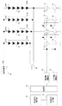
図1は、本発明の実施形態に係る液晶ディスプレイ用のバックライト装置の概略構成を示す図である。以下、図1を参照して、本発明の第一の実施例による液晶ディスプレイ用のバックライト装置の構成を説明する。なお、本発明の画像表示装置は液晶ディスプレイに限られず、照明装置は液晶ディスプレイ用のバックライト装置に限られるものではない。
Example 1
FIG. 1 is a diagram showing a schematic configuration of a backlight device for a liquid crystal display according to an embodiment of the present invention. Hereinafter, the configuration of a backlight device for a liquid crystal display according to a first embodiment of the present invention will be described with reference to FIG. The image display device of the present invention is not limited to a liquid crystal display, and the illumination device is not limited to a backlight device for a liquid crystal display.
図1に示す液晶ディスプレイ用のバックライトは、LED列10、20、30、40、LED駆動用定電流回路部11、21、31、41、スイッチング回路部12、22、32、42を有する。このバックライトは独立に発光を制御可能な複数の発光領域から構成され、各LED列は各発光領域の光源である。また、本実施例のバックライト装置は、画像信号入力部50、画像信号解析部51、制御部52、電流量調整部53、パルス幅調整部54、最大LED列降下電圧検出回路部55、電源回路部56、最小LED列降下電圧検出回路部57、及び電圧比較部58を有する。LED列とLED駆動用定電流回路部及びスイッチング回路部との接続関係は、LED列10にLED駆動用定電流回路部11とスイッチング回路部12が直列接続されている。LED列20、LED列30、及びLED列40についても、LED列とLED駆動用定電流回路部及びスイッチング回路部との接続関係はLED列10と同様とする。
The backlight for a liquid crystal display shown in FIG. 1 has
次に各構成要件の詳細を説明する。
LED列10、20、30、40は、複数のLEDが直列に接続されて構成される光源である。1つのLED列に接続されるLEDの数量は、液晶ディスプレイに要求される輝度や電源回路が出力できる電圧値、ローカルディミングを行うバックライトではローカルディミングの分解能等から決定されるものとする。
Next, details of each component will be described.
The
LED駆動用定電流回路部11、21、31、41は、各LED列10、20、30、40に電流供給を行う。LED駆動用定電流回路部11、21、31、41は、各LED列10、20、30、40に対応した液晶ディスプレイの分割エリアに要求される明るさでLEDを点灯させるために必要な一定の電流を流す回路である。電流量は、後述する電流量調整部53からの指示によって調整される。
The LED drive constant
スイッチング回路部12、22、32、42は、各LED列10、20、30、40に流す定電流をスイッチング素子でON/OFFすることで明るさを調整する回路である。一般的には、スイッチング回路部は、FETやトランジスタ等のスイッチング素子で構成される。
The switching
画像信号入力部50は、撮像装置(図示しない)や画像信号再生装置(図示しない)から出力される画像信号を受信する。
画像信号解析部51は、画像信号入力部50が受信した画像信号のデコード及び解析を行う。本発明においては、ローカルディミング等を行う際、液晶ディスプレイを仮想的にマトリクス分割したときの分割エリアごとの明暗を分析し、分析結果を後述する制御部52へ送信する。また、画像信号解析部51は、デコードした画像信号を液晶ディスプレイ(図示しない)へ送信する。
The image
The image
制御部52は、画像信号解析部51や、後述する電流量調整部53、パルス幅調整部54、電圧比較部58で行う動作を指示するブロックであり、マイコンやFPGA等で構成される。具体的には、制御部52は、画像信号解析部51から受信した液晶ディスプレイの分割エリアごとの明暗を分析した結果に基づいて、分割エリアに対応したLED列10、20、30、40の明るさを決定する。そして、制御部52は、決定された明るさを実現するLED駆動条件を計算し、その結果を電流量調整部53及びパルス幅調整部54へ送信する。また、電圧比較部58の比較結果を電流量調整部53の制御やLEDのVF基準値等へ反映させる。VF基準値については後述する。
The
電流量調整部53は、LED列10、20、30、40と直列接続されているLED駆動用定電流回路部11、21、31、41が流す定電流を調整する回路である。電流量調整部53は、ローカルディミング制御を行う場合、各LED列が対応する領域の画像信号の内容(輝度等の特徴量)に応じて各LED駆動用定電流回路部の電流量を調整することで各LED列に供給する電流制御を行う。
The current
パルス幅調整部54は、スイッチング回路部12、22、32、42のON/OFF比率を調整するためのパルス駆動波形を出力する回路である。パルス幅調整部54は、ローカルディミング制御を行う場合、各LED列が対応する分割エリアの画像信号の内容に応じてON/OFF比率を調整する。パルス幅調整部54は、各LED列の点灯期間と消灯期間を調整することにより、各LED列の点灯制御を行う。
The pulse
最大LED列降下電圧検出回路部55は、LED列10、20、30、40の電圧降下量VF10、VF20、VF30、VF40のうちの最も大きい値VFMaxを検出する。すなわち、最大LED列降下電圧検出回路部55は、LED駆動用定電流回路部11、21、31、41の両端電圧V11、V21、V31、V41のうちの最も小さな値を検出する。そして、最大LED列降下電圧検出回路部55は、検出したVFMaxを電源回路部56及び電圧比較部58へ送信する。
The maximum LED string drop voltage
電源回路部56は、LED列10、20、30、40を点灯させるために必要な電圧を生成する電源回路である。電源回路部56は、出力電圧Voutが、LED列10、20、30、40のうち、最もVFが高いLED列の電圧VFMaxにLED駆動用定電流回路部11、21、31、41を動作させるために必要な電圧VCを加えた電圧となるように、電源制御を行う。
The power
最小LED列降下電圧検出回路部57は、LED列10〜40に電流が流れている期間、スイッチング回路部12〜42がONしている期間において、LED列10〜40の電圧降下量VF10〜VF40のうちの最も小さな値VFMinを検出する。そして、最小LED列降下電圧検出回路部57は、VFMinを電圧比較部58へ送信する。
The minimum LED string drop voltage
電圧比較部58は、最大LED列降下電圧検出回路部55が検出したVFMaxと、最小LED列降下電圧検出回路部57が検出したVFMinとを比較する。VFMaxとVFMinの差分と、LED駆動用定電流回路部11、21、31、41を駆動するために必要な電圧値とを足し合わせた電圧値が、VFMinのLED列に対応するLED駆動用定電流回路部にかかる電圧である。この電圧値がLED駆動用定電流回路部の許容値を超えないように定電流回路が流す電流値を調整することが本発明の特徴である。
The
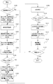
次に、制御部52が行う一連の操作について図2を用いて説明する。
まず、制御部52は、ユーザーからの電源ON操作を受けて、本発明の制御を開始する。
次に、制御部52は、ステップS100において、今回の指示による電源ONが本機体
において初回の電源ONか否かを判断する。初回電源ONの場合、制御部52は、バックライト装置の全LED列に同一の基準電流値Iを流して、このときの各LED列のVF値VF10、VF20、VF30、VF40を測定し、各LED列のVF基準値としてメモリに保存する(S101)。本実施例では、このVF基準値に基づいて、各LED列のVF値が標準的な値(TYP値)に対してどの程度ばらついているかを推測し、各LED列の電流値IFを変動させたときのVFの変動を予想するために使用する。初回電源ONでない場合、制御部52は、ステップS102へ進む。
Next, a series of operations performed by the
First, the
Next, in step S100, the
次に、ステップS102において、制御部52は画像信号解析部51に画像信号入力部50から受信した画像信号の解析を行うよう指示する。画像信号解析部51は、画像信号をデコードしたのち、画像信号の各画素の輝度値を解析する。制御部52は、画像信号解析部51が解析した画像信号の輝度値をもとに液晶ディスプレイを仮想的にマトリクス分割した時の分割エリアごとに必要な明るさを計算する。
Next, in step S102, the
次に、ステップS103において、制御部52は、S103で計算した分割エリアごとに必要な明るさをもとに、分割エリアと各LED列の対応関係に基づいてLED列10、20、30、40が発光しなければならない発光量を計算する。
Next, in step S103, the
次に、ステップS104において、制御部52は、S103で計算した各LED列に必要な発光量に基づいて、電流量調整部53とパルス幅調整部54の調整値を決定する。ここで、ある発光量を実現するときに電流量とパルス幅をどのように決定するかを説明する。一般的に青色系及び緑色系のLEDは電流量の変動によって主波長が変化するため、電流量での調整は最小限にとどめたいことが多い。そのため、明るさを調整する際はまず電流値を規定電流値にした状態でパルス幅調整部54にて調整を行う。そして、パルス幅調整部54の調整値の上限値に調整(つまり直流駆動状態)してもLED列が必要輝度を実現できない場合に電流量調整部53にて電流量を増加させることとする。
Next, in step S104, the
次に、ステップS105において、制御部52は、各LED列10、20、30、40のVF値VF10、VF20、VF30、VF40の理論値を取得する。理論値の取得は次のようにして行う。すなわち、使用しているLEDのVFとIFの関係を示すカーブの情報をあらかじめ記憶装置(不図示)に保存しておき、このカーブとステップS101で保存したVF基準値及び各LED列の電流量IFから算出する。ここで計算した各LED列の理論VF値のうち、最大値をVFMax、最小値をVFMinとする。
Next, in step S105, the
次に、ステップS106において、制御部52は、S105で算出した各LED列の理論VF値の最大値VFMaxと最小値VFMinの差分を算出し、この差分があらかじめ定められている規定値VLimitより小さいか否かを判定する。本実施例において、既定値VLimitは、LED駆動用定電流回路部が許容できる電圧値に基づいて定める閾値である。
Next, in step S106, the
ステップS106において、理論VF値の最大値VFMaxと最小値VFMinの差分が規定値VLimit以上となる場合、制御部52は、LED駆動用定電流回路部を保護するために最小VF値となるLED列の電流量を調整する。(S107)
In step S106, when the difference between the maximum value VFMax and the minimum value VFmin of the theoretical VF value is equal to or greater than the specified value VLimit, the
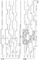
ここで、ステップS107、S108で行う電流量調整の例について図3、図4、図5、及び図6を用いて説明する。
図3及び図4は、nフレーム目、n+1フレーム目、n+2フレーム目で入力される画像信号の内容に応じて、バックライトを構成する各LED列の電流量とパルス幅を調整している様子を示している。図3が実施例1適用前のLED点灯チャート、図4が実施例1適用後のLED点灯チャートである。また、図5は、実施例1で使用するLEDの電流量
IFの変化に対する電圧降下量VFの変化を示す図である。また、図6は、実施例1で使用するLEDの電流量IFの変化に対する発光量の変化を示す図である。
Here, examples of current amount adjustment performed in steps S107 and S108 will be described with reference to FIGS. 3, 4, 5, and 6. FIG.
In FIGS. 3 and 4, the current amount and pulse width of each LED array constituting the backlight are adjusted according to the contents of the image signal input in the nth frame, the n + 1th frame, and the n + 2th frame. Is shown. FIG. 3 is an LED lighting chart before application of the first embodiment, and FIG. 4 is an LED lighting chart after application of the first embodiment. FIG. 5 is a diagram illustrating a change in the voltage drop amount VF with respect to a change in the current amount IF of the LED used in the first embodiment. FIG. 6 is a diagram showing a change in the light emission amount with respect to a change in the current amount IF of the LED used in the first embodiment.
図3によると、実施例1適用前はnフレーム目で全LED列が基準電流Iで点灯しており、このとき全LED列のVF値はともにV1の値を示している。電源回路部56の出力電圧Voutは、V1にLED駆動用定電流回路部が駆動するために必要な電圧VCを加え、Vout=V1+VCとなる。ここで、n+1フレーム目の画像信号を解析した結果、LED列10に対応するエリアの輝度を上げる必要があるため、電流量IF10を2Iへ増やすこととなった。この結果、LED列10のVF値であるVF10は図5の関係からV2へ増える見込みとなる。このとき、電源回路部56はLED列10のVF値がV2へ変化することに伴ってVout=V2+VCの電圧を出力するため、LED列10とLED列20のVF値の差分はV2−V1となりVLimit以上となってしまう。
According to FIG. 3, before the application of Example 1, all the LED strings are lit with the reference current I in the nth frame, and at this time, the VF values of all the LED strings indicate the value of V1. The output voltage Vout of the power
ここで、LED列20に対して本実施例を適用する。図3のタイミングチャートに対して実施例1を適用したときのタイミングチャートを図4に示す。図3においてLED列10とLED列20のVF値の差分をVLimitより小さくするためにはLED列20のVF値であるVF20をV3にすればよいこととする。図5からLED列20のVF値VF20をV3とするための電流量を求めると、電流量Iに対応する電圧降下量V1、電流量2Iに対応する電圧降下量V2に対し、電圧降下量をV3とするためには電流量を1.5Iにすればよいことがわかる。よって、制御部52は電流量調整部53に対してLED駆動用定電流回路部21が流す電流量を1.5Iとするよう指示する。(S107)
Here, the present embodiment is applied to the
次に、制御部52は、ステップS108においてLED列20へ流す電流量を1.5Iとしたときの単位時間あたりの発光量からパルス幅調整部54のON/OFF比率を決定する。LEDに流す単位時間あたりの発光量と電流量の関係は図6に示す。図6から、電流量I時の単位時間あたりの発光量Ivに対し、電流量が1.5Iとなったときの単位時間あたりの発光量は1.45Ivとなっていることがわかる。
Next, the
ここで図3へ戻り、LED列20の点灯状態を確認すると、LED列10の電流量が2Iとなっている区間AにおいてLED列20が点灯している時間はt2、t3、区間Aの直前の点灯時間はt1、区間Aの直後の点灯時間はt4である。図3のnフレーム目におけるLED列20の発光量を計算すると

ここで、実施例1適用後の図4におけるLED列20の発光量を、上記のように計算された図3に基づく値と同一にすることを考える。LED列20は後詰めで点灯しているた
めt2とt4の時間は変更できない(1周期の点灯パターンにおいて点灯終了タイミングは調整できない)。よって、nフレーム目の発光量は、電流量Iで点灯している時間をTnとすれば、
同様にn+1フレーム目についても計算すると、電流量1.5Iで点灯する時間をTn+1とすれば、
同様にLED列30、40についても電流量を1.5IとしてLED列30,40のVFをV3とし、LED列の発光時間を調整することで、VFMax−VFMinをVLimitより小さくすることができる。
Here, let us consider that the light emission amount of the
Similarly, when calculating for the (n + 1) th frame, if the lighting time at a current amount of 1.5I is Tn + 1 ,
Similarly, for the LED strings 30 and 40, VFMax-VFMi can be made smaller than VLimit by adjusting the light emission time of the LED strings 30 and 40 by setting the current amount to 1.5I and V3 of the LED strings 30 and 40 to V3.
次に、制御部52は、ステップS109において、全LED列10、20、30、40を発光させるため、電流量調整部53及びパルス幅調整部54を制御する。電流量調整部53及びパルス幅調整部54は、制御部52からの指示に従い、LED駆動用定電流回路部11、21、31、41、及びスイッチング回路部12、22、32、42は、制御部52で計算した状態でLED列が点灯するように動作する。
Next, in step S109, the
次に、制御部52は、ステップS110において、電圧比較部58に対してVFMaxとVFMinの比較を行うよう指示する。ここで、実際に点灯したときのVF値を観測し
、VF値の差分がVLimitより小さくなっているか否かを確認する。ここで、VF値の差分がVLimit以上となっている場合、制御部52は、ステップS111へ進み、VF基準値を更新する。
Next, in step S110, the
全LED列が点灯したのち、ステップS112では、最大LED列降下電圧検出回路部55が最大LED列降下電圧の検出結果を電源回路部56へフィードバックする。
電源回路部56は、ステップS113において、最大LED列降下電圧の検出結果に基づいて出力電圧Voutを調整する(図4の例ではV2+VCに調整する)。
制御部52は、上記一連の操作をユーザーからの電源OFF指示があるまで繰り返す。(S114)
After all the LED strings are turned on, the maximum LED string drop voltage
In step S113, the power
The
以上が、実施例1の電流量制御である。本実施例によると、ローカルディミングを行うバックライトにおいて、電圧調整素子を追加せずにLED駆動用定電流回路部を保護することができる。
なお、上記の例では、VFMinとなるLED列の電流量を調整することを説明したが、本発明では、VF値がVFMaxに対し閾値以上小さいLED列に供給する電流を増やす制御を行う。従って、VF民となるLED列以外のLED列のうちにVF値とVFMaxとの差分がVLimit以上となるものがある場合は、そのLED列についても電流量を調整する。
The above is the current amount control of the first embodiment. According to the present embodiment, the constant current circuit unit for driving the LED can be protected without adding a voltage adjusting element in the backlight that performs local dimming.
In the above example, adjustment of the current amount of the LED string that becomes VFMin has been described. However, in the present invention, control is performed to increase the current supplied to the LED string whose VF value is smaller than the threshold by VFMax. Accordingly, when there is an LED array other than the LED array that becomes the VF citizen, the difference between the VF value and VFMax is equal to or greater than VLimit, the current amount is also adjusted for the LED array.
(実施例2)
実施例2は、LED列10、20、30、40の発光量調整をフレーム期間毎に実行する実施例である。
(Example 2)
The second embodiment is an embodiment in which the light emission amount adjustment of the
実施例1では、電流量や点灯期間の調整を行う時間的単位がフレーム期間に制限されなかったため、LED列10の電流量が増えるタイミングと他のLED列の電流量を増やすタイミングとを同期させることができた。しかし、制御部52の仕様によっては電流量調整部53及びパルス幅調整部54への制御がフレーム単位となっている場合もある。実施例2はこのような場合であっても電流量制御によって、電圧調整素子を追加せずにLED駆動用定電流回路部を保護できることを説明する。
In the first embodiment, since the time unit for adjusting the current amount and the lighting period is not limited to the frame period, the timing at which the current amount of the
実施例2の電流量制御について図7を用いて説明する。図7は、図3のタイミングチャートに対して、実施例2を適用したときの全LED列のタイミングチャートである。
実施例2では、制御部52は、画像信号解析部51に対し、nフレーム目とn+1フレーム目の両方の画像信号の解析を指示する。
画像信号解析部51は、nフレーム目とn+1フレーム目の画像信号を解析し、2フレーム分の分割エリアごとの明暗分析結果を制御部52へ送信する。
The current amount control according to the second embodiment will be described with reference to FIG. FIG. 7 is a timing chart of all LED rows when Example 2 is applied to the timing chart of FIG.
In the second embodiment, the
The image
制御部52は、画像信号解析部51から受信した2フレーム分の分析結果をもとに各LED列10、20、30、40が発光しなければならない発光量を計算する。そして、制御部52は、計算した各LED列に必要な発光量に基づいて、電流量調整部53とパルス幅調整部54の調整値を決定する。
The
計算の結果を図7に示す。図7によると、n+1フレーム目においてLED列10の電流量を2Iに増やすことになったとする。よって、LED列10の電流量が増えている期間において、VFMaxとVFMinの差分がVLimitを超える可能性があるため、LED列20、30、40の電流量を調整する。
The result of the calculation is shown in FIG. According to FIG. 7, it is assumed that the current amount of the
ここで、実施例2では、LED列10の電流量が2Iとなっている区間Aにおいて、LED列20、30、40が点灯しているか否かを判断する。すなわち、発光量が増加する
LED列10の区間Aと、LED列20、30、40の点灯期間とが、少なくとも一部において重なるか判断する。そして、そのような点灯期間が含まれるLED列20、30、40のフレーム期間において、LED列20、30、40の電流量を増やす制御を行う。図7によると、区間Aと同時に点灯しているのは、LED列20のnフレーム目及びn+1フレーム目、LED列30のnフレーム目、及びLED列40のnフレーム目であることがわかる。なお、実施例2では、光源毎に、1フレーム期間の開始タイミングが異なっている場合の例である。光源毎に1フレーム期間の開始タイミングが異なっていなくても良い。
Here, in Example 2, it is determined whether or not the
よって、制御部52は、LED列20のnフレーム目及びn+1フレーム目、LED列30のnフレーム目、及びLED列40のnフレーム目に対して電流量調整を行う。ここで、LED列20、30,40のVF値V3は、電流量I時のVF値V1と電流量2I時のVF値V2の間の値となるように決定し、かつ、V1との差分及びV2との差分がともにVLimit以下となるように決定する。計算を簡略化する場合は、
以上が、実施例2の電流量制御処理である。本実施例によると、各LED列の電流量をフレーム単位で調整する場合であっても電流量制御処理によって、電圧調整素子を追加せずにLED駆動用定電流回路部を保護できる。 The above is the current amount control processing of the second embodiment. According to the present embodiment, even when the current amount of each LED array is adjusted in units of frames, the LED drive constant current circuit unit can be protected without adding a voltage adjusting element by the current amount control process.
(実施例3)
実施例3は、前述の実施例1、実施例2に対し、各LED列の電流調整量に制約を持たせる点が異なっている。
図8及び図9は、実施例3で使用するLEDの電流量と発光効率の関係を示したものである。図8によると、実施例3で使用するLEDの発光効率は、電流量がI3のときに最も高くなっていることがわかる。また、図8によると、輝度を増加させたLED列のVF値(V2)と、その他のLED列のVF値との差分がVLimit以下となる範囲は図8の黒枠内である。このようなLED特性の場合、輝度を増加させたLED列以外の電流値を、最も発光効率が高いI3とするのが実施例3の特徴である。
Example 3
The third embodiment is different from the first and second embodiments described above in that the current adjustment amount of each LED array is limited.
8 and 9 show the relationship between the amount of current of the LEDs used in Example 3 and the light emission efficiency. As can be seen from FIG. 8, the luminous efficiency of the LED used in Example 3 is the highest when the amount of current is I3. Further, according to FIG. 8, the range in which the difference between the VF value (V2) of the LED array whose luminance is increased and the VF values of the other LED arrays is equal to or less than VLimit is within the black frame of FIG. In the case of such LED characteristics, it is a feature of the third embodiment that the current value other than the LED array with increased luminance is set to I3 having the highest luminous efficiency.
また、図9のように電流と発光効率が反比例の特性となるLEDの場合は、電流量の増加を最小限とし、発光効率の低下を抑えるため、輝度を増加させたLED列以外の電流値を、V2との差分がVLimitより小さい範囲内で最小の電流値であるI4とする。 In addition, in the case of an LED having an inversely proportional characteristic between current and light emission efficiency as shown in FIG. 9, the current value other than the LED array with increased luminance is used to minimize the increase in the amount of current and suppress the decrease in light emission efficiency. Is I4 which is the minimum current value within a range where the difference from V2 is smaller than VLimit.
以上が、実施例3の電流量制御である。本実施例によると、輝度を増加させたLED列以外のLED列の電流量を決定する際、輝度を増加させたLED列のVF値とその他のLED列とのVF値の差分がVLimitに収まる範囲内で最も発光効率が高い電流量が採用される。従って、で発光効率の低減を最小限にとどめてLED駆動用定電流回路部を保護することができる。 The above is the current amount control of the third embodiment. According to the present embodiment, when determining the current amount of the LED strings other than the LED string whose luminance is increased, the difference between the VF value of the LED string whose luminance is increased and the VF value of the other LED strings is within VLimit. The amount of current with the highest luminous efficiency within the range is employed. Therefore, it is possible to protect the LED driving constant current circuit section with minimal reduction in luminous efficiency.
10 LED列、11 LED列10用定電流回路、20 LED列、21 LED列20用定電流回路、30 LED列、31 LED列30用定電流回路、40 LED列、41 LED列40用定電流回路、52 制御部、53 電流量調整部、56 電源回路部
DESCRIPTION OF
Claims (33)
前記複数の光源の各々に電流を供給する複数の電流供給手段と、
前記複数の光源の電圧降下の最大値に応じて前記複数の光源に接続される電源の出力電圧を制御する電源制御手段と、
前記複数の光源の電圧降下の最小値と最大値との差分が閾値より小さくなるように、前記電流供給手段が前記各光源へ供給する電流量を制御する電流制御手段と、
を備える照明装置。 Multiple light sources;
A plurality of current supply means for supplying a current to each of the plurality of light sources;
Power supply control means for controlling the output voltage of the power supply connected to the plurality of light sources according to the maximum value of the voltage drop of the plurality of light sources;
Current control means for controlling the amount of current that the current supply means supplies to each of the light sources so that the difference between the minimum value and the maximum value of the voltage drop of the plurality of light sources is smaller than a threshold value;
A lighting device comprising:
前記点灯制御手段は、前記電流制御手段の前記制御により電流量が増える光源の点灯期間を短くする請求項2又は3に記載の照明装置。 A lighting control means for controlling a lighting period and a lighting period of each light source;
The lighting device according to claim 2, wherein the lighting control unit shortens a lighting period of a light source in which a current amount increases by the control of the current control unit.
前記光源に供給する電流量と電圧降下の関係に基づき、前記決定手段により決定される電流量に応じた前記各光源の電圧降下を取得する取得手段と、
を更に備え、
前記電流制御手段は、前記取得手段により取得される前記複数の光源の電圧降下の最小値と最大値との差分が閾値以上の場合、電圧降下が前記最大値に対し閾値以上小さい光源について前記決定手段が決定した電流量を増やす請求項1〜5のいずれか1項に記載の照明装置。 Determining means for determining a light emission amount of each light source, and determining a current amount to be supplied to each light source and a lighting period of each light source according to the light emission amount;
Based on the relationship between the amount of current supplied to the light source and the voltage drop, acquisition means for acquiring the voltage drop of each light source according to the amount of current determined by the determination means;
Further comprising
When the difference between the minimum value and the maximum value of the voltage drop of the plurality of light sources acquired by the acquisition unit is equal to or greater than a threshold value, the current control unit determines the light source whose voltage drop is smaller than the threshold value by a threshold value or more. The lighting device according to claim 1, wherein the amount of current determined by the means is increased.
前記取得手段は、前記検出手段により前記各光源の電圧降下を取得する請求項6に記載の照明装置。 Further comprising detection means for detecting a voltage drop of each light source,
The illumination device according to claim 6, wherein the acquisition unit acquires a voltage drop of each light source by the detection unit.
前記決定手段は、画像信号に応じて前記各光源の発光量を決定する請求項6〜9のいず
れか1項に記載の照明装置。 It further comprises input means for inputting an image signal,
The lighting device according to any one of claims 6 to 9, wherein the determining unit determines a light emission amount of each light source according to an image signal.
前記複数の光源の各々は前記複数の発光領域の各々に対応しており、
前記決定手段は、前記各発光領域に対応する領域の画像の特徴量に基づき前記各発光領域に対応する光源の発光量を決定する請求項10に記載の照明装置。 The lighting device is composed of a plurality of light emitting areas,
Each of the plurality of light sources corresponds to each of the plurality of light emitting regions,
The lighting device according to claim 10, wherein the determination unit determines a light emission amount of a light source corresponding to each light emission region based on a feature amount of an image of a region corresponding to each light emission region.
前記電流制御手段は、前記取得手段により取得される前記複数の光源の電圧降下の最小値と最大値との差分が閾値以上となるフレーム期間において、電圧降下が前記最大値に対し閾値以上小さい光源について前記決定手段が決定した電流量を増やす請求項6〜11のいずれか1項に記載の照明装置。 The determining means determines the light emission amount of each light source for each frame period of the input image signal,
The current control means is a light source whose voltage drop is smaller than the maximum value by a threshold with respect to the maximum value in a frame period in which the difference between the minimum value and the maximum value of the voltage drops of the plurality of light sources acquired by the acquisition means is not less than the threshold value. The lighting device according to claim 6, wherein the current amount determined by the determining unit is increased.
前記電流制御手段は、電圧降下が前記最大値に対し閾値以上小さい光源のうち、その点灯期間と、前記取得手段により取得される前記複数の光源の電圧降下の最小値と最大値との差分が閾値以上となる期間とが、少なくとも一部において重なる光源について、当該点灯期間が含まれるフレーム期間において、前記電流量を増やす制御を行う請求項13に記載の照明装置。 The start timing of the frame period is different between two or more of the plurality of light sources,
The current control means includes a lighting period of light sources whose voltage drop is smaller than the maximum value by a threshold value or more, and a difference between the minimum value and the maximum value of the voltage drop of the plurality of light sources acquired by the acquisition means. The lighting device according to claim 13, wherein a control for increasing the amount of current is performed in a frame period including the lighting period for a light source that overlaps at least part of a period that is equal to or greater than a threshold value.
前記複数の光源の各々に電流を供給する複数の電流供給手段と、
前記複数の光源に接続される電源と、
を備える照明装置の制御方法であって、
前記複数の光源の電圧降下の最大値に応じて前記電源の出力電圧を制御する電源制御工程と、
前記複数の光源の電圧降下の最小値と最大値との差分が閾値より小さくなるように、前記電流供給手段が前記各光源へ供給する電流量を制御する電流制御工程と、
を備える照明装置の制御方法。 Multiple light sources;
A plurality of current supply means for supplying a current to each of the plurality of light sources;
A power source connected to the plurality of light sources;
A method for controlling a lighting device comprising:
A power supply control step of controlling the output voltage of the power supply according to the maximum value of the voltage drop of the plurality of light sources;
A current control step of controlling the amount of current supplied to the light sources by the current supply means so that the difference between the minimum value and the maximum value of the voltage drop of the plurality of light sources is smaller than a threshold value;
The control method of an illuminating device provided with.
内で光源の発光効率が最も高くなる電流量とする請求項19に記載の照明装置の制御方法。 In the current control step, the amount of current supplied to the light source whose voltage drop is smaller than the maximum value by a threshold value or less is set within a range where the difference between the minimum value and the maximum value of the voltage drop of the plurality of light sources is smaller than the threshold value. The control method of the illuminating device according to claim 19, wherein the current amount is the highest in luminous efficiency.
前記点灯制御工程では、前記電流制御工程での前記制御により電流量が増える光源の点灯期間を短くする請求項19又は20に記載の照明装置の制御方法。 A lighting control step of controlling a lighting period and a lighting period of each light source;
The lighting device control method according to claim 19 or 20, wherein in the lighting control step, a lighting period of a light source in which a current amount is increased by the control in the current control step is shortened.
前記光源に供給する電流量と電圧降下の関係に基づき、前記決定工程で決定される電流量に応じた前記各光源の電圧降下を取得する取得工程と、
を更に備え、
前記電流制御工程では、前記取得工程で取得される前記複数の光源の電圧降下の最小値と最大値との差分が閾値以上の場合、電圧降下が前記最大値に対し閾値以上小さい光源について前記決定工程で決定した電流量を増やす請求項18〜22のいずれか1項に記載の照明装置の制御方法。 Determining a light emission amount of each light source, and determining a current amount to be supplied to each light source and a lighting period of each light source according to the light emission amount;
Based on the relationship between the amount of current supplied to the light source and the voltage drop, an acquisition step of acquiring the voltage drop of each light source according to the amount of current determined in the determination step;
Further comprising
In the current control step, when the difference between the minimum value and the maximum value of the voltage drop of the plurality of light sources acquired in the acquisition step is greater than or equal to a threshold value, the determination is made on a light source whose voltage drop is smaller than the threshold value by the threshold value or more. The control method of the illuminating device of any one of Claims 18-22 which increase the amount of electric current determined at the process.
前記取得工程では、前記検出手段により前記各光源の電圧降下を取得する請求項23に記載の照明装置の制御方法。 The illumination device further includes detection means for detecting a voltage drop of each light source,
24. The method of controlling an illumination device according to claim 23, wherein in the obtaining step, the voltage drop of each light source is obtained by the detection means.
前記決定工程では、画像信号に応じて前記各光源の発光量を決定する請求項23〜26のいずれか1項に記載の照明装置の制御方法。 It further has an input process for inputting an image signal,
27. The method for controlling an illuminating device according to any one of claims 23 to 26, wherein in the determining step, a light emission amount of each light source is determined according to an image signal.
前記複数の光源の各々は前記複数の発光領域の各々に対応しており、
前記決定工程では、前記各発光領域に対応する領域の画像の特徴量に基づき前記各発光領域に対応する光源の発光量を決定する請求項27に記載の照明装置の制御方法。 The lighting device is composed of a plurality of light emitting areas,
Each of the plurality of light sources corresponds to each of the plurality of light emitting regions,
28. The method of controlling an illumination device according to claim 27, wherein, in the determining step, a light emission amount of a light source corresponding to each light emitting region is determined based on a feature amount of an image of a region corresponding to each light emitting region.
前記電流制御工程では、前記取得工程で取得される前記複数の光源の電圧降下の最小値と最大値との差分が閾値以上となるフレーム期間において、電圧降下が前記最大値に対し閾値以上小さい光源について前記決定工程で決定した電流量を増やす請求項23〜28のいずれか1項に記載の照明装置の制御方法。 In the determining step, the light emission amount of each light source is determined for each frame period of the input image signal,
In the current control step, in the frame period in which the difference between the minimum value and the maximum value of the voltage drop of the plurality of light sources acquired in the acquisition step is greater than or equal to a threshold value, the light source has a voltage drop that is smaller than the threshold value by the threshold value or less. The method for controlling an illumination device according to any one of claims 23 to 28, wherein the current amount determined in the determination step is increased.
前記電流制御工程では、電圧降下が前記最大値に対し閾値以上小さい光源のうち、その点灯期間と、前記取得工程で取得される前記複数の光源の電圧降下の最小値と最大値との差分が閾値以上となる期間とが、少なくとも一部において重なる光源について、当該点灯期間が含まれるフレーム期間において、前記電流量を増やす制御を行う請求項30に記載の照明装置の制御方法。 The start timing of the frame period is different between two or more of the plurality of light sources,
In the current control step, among the light sources whose voltage drop is smaller than the threshold value by the threshold value or more, the difference between the lighting period and the minimum value and the maximum value of the voltage drop of the plurality of light sources acquired in the acquisition step is The lighting device control method according to claim 30, wherein control is performed to increase the amount of current in a frame period including the lighting period for a light source that overlaps at least in part with a period equal to or greater than a threshold value.
Priority Applications (1)
| Application Number | Priority Date | Filing Date | Title |
|---|---|---|---|
| JP2013100516A JP2014220200A (en) | 2013-05-10 | 2013-05-10 | Illuminating device and control method thereof |
Applications Claiming Priority (1)
| Application Number | Priority Date | Filing Date | Title |
|---|---|---|---|
| JP2013100516A JP2014220200A (en) | 2013-05-10 | 2013-05-10 | Illuminating device and control method thereof |
Publications (2)
| Publication Number | Publication Date |
|---|---|
| JP2014220200A true JP2014220200A (en) | 2014-11-20 |
| JP2014220200A5 JP2014220200A5 (en) | 2016-06-16 |
Family
ID=51938458
Family Applications (1)
| Application Number | Title | Priority Date | Filing Date |
|---|---|---|---|
| JP2013100516A Pending JP2014220200A (en) | 2013-05-10 | 2013-05-10 | Illuminating device and control method thereof |
Country Status (1)
| Country | Link |
|---|---|
| JP (1) | JP2014220200A (en) |
Cited By (7)
| Publication number | Priority date | Publication date | Assignee | Title |
|---|---|---|---|---|
| CN105307353A (en) * | 2015-11-24 | 2016-02-03 | 成都芯源系统有限公司 | LED driver, and fault protection circuit and fault protection method for LED driver |
| CN106524081A (en) * | 2016-11-16 | 2017-03-22 | 南京东晖光电有限公司 | LED matrix illumination drive and control system |
| WO2017094555A1 (en) * | 2015-11-30 | 2017-06-08 | シャープ株式会社 | Method for testing led backlight |
| WO2019033853A1 (en) * | 2017-08-18 | 2019-02-21 | 京东方科技集团股份有限公司 | Method and apparatus for adjusting backlight source |
| CN110619853A (en) * | 2018-06-19 | 2019-12-27 | 电力集成公司 | Power converter with current matching |
| CN113556848A (en) * | 2020-04-24 | 2021-10-26 | 中强光电股份有限公司 | Light emitting device and light generating method |
| EP4005348B1 (en) | 2019-07-24 | 2023-05-31 | eldoLAB Holding B.V. | Smart starting up method by an led driver |
Citations (5)
| Publication number | Priority date | Publication date | Assignee | Title |
|---|---|---|---|---|
| JP2009157189A (en) * | 2007-12-27 | 2009-07-16 | Sony Corp | Light source system, light source control device, light source device, and image display method |
| JP2010161264A (en) * | 2009-01-09 | 2010-07-22 | Renesas Technology Corp | Led drive circuit, semiconductor element, and image display device |
| JP2010287601A (en) * | 2009-06-09 | 2010-12-24 | Panasonic Corp | Light emitting element drive unit |
| JP2011243788A (en) * | 2010-05-19 | 2011-12-01 | Sony Corp | Light-emitting element driving device, and display device |
| JP2013089777A (en) * | 2011-10-18 | 2013-05-13 | Sharp Corp | Light-emitting element drive device |
-
2013
- 2013-05-10 JP JP2013100516A patent/JP2014220200A/en active Pending
Patent Citations (5)
| Publication number | Priority date | Publication date | Assignee | Title |
|---|---|---|---|---|
| JP2009157189A (en) * | 2007-12-27 | 2009-07-16 | Sony Corp | Light source system, light source control device, light source device, and image display method |
| JP2010161264A (en) * | 2009-01-09 | 2010-07-22 | Renesas Technology Corp | Led drive circuit, semiconductor element, and image display device |
| JP2010287601A (en) * | 2009-06-09 | 2010-12-24 | Panasonic Corp | Light emitting element drive unit |
| JP2011243788A (en) * | 2010-05-19 | 2011-12-01 | Sony Corp | Light-emitting element driving device, and display device |
| JP2013089777A (en) * | 2011-10-18 | 2013-05-13 | Sharp Corp | Light-emitting element drive device |
Cited By (11)
| Publication number | Priority date | Publication date | Assignee | Title |
|---|---|---|---|---|
| CN105307353A (en) * | 2015-11-24 | 2016-02-03 | 成都芯源系统有限公司 | LED driver, and fault protection circuit and fault protection method for LED driver |
| CN105307353B (en) * | 2015-11-24 | 2018-06-22 | 成都芯源系统有限公司 | LED driver and its fault secure circuit and fault protecting method |
| WO2017094555A1 (en) * | 2015-11-30 | 2017-06-08 | シャープ株式会社 | Method for testing led backlight |
| CN106524081A (en) * | 2016-11-16 | 2017-03-22 | 南京东晖光电有限公司 | LED matrix illumination drive and control system |
| WO2019033853A1 (en) * | 2017-08-18 | 2019-02-21 | 京东方科技集团股份有限公司 | Method and apparatus for adjusting backlight source |
| US10789896B2 (en) | 2017-08-18 | 2020-09-29 | Beijing Boe Special Display Technology Co., Ltd. | Method and device for adjusting a backlight |
| CN110619853A (en) * | 2018-06-19 | 2019-12-27 | 电力集成公司 | Power converter with current matching |
| CN110619853B (en) * | 2018-06-19 | 2024-01-05 | 电力集成公司 | Power converter with current matching |
| JP7455458B2 (en) | 2018-06-19 | 2024-03-26 | パワー・インテグレーションズ・インコーポレーテッド | Power converter with current matching |
| EP4005348B1 (en) | 2019-07-24 | 2023-05-31 | eldoLAB Holding B.V. | Smart starting up method by an led driver |
| CN113556848A (en) * | 2020-04-24 | 2021-10-26 | 中强光电股份有限公司 | Light emitting device and light generating method |
Similar Documents
| Publication | Publication Date | Title |
|---|---|---|
| JP2014220200A (en) | Illuminating device and control method thereof | |
| US8044918B2 (en) | Back light apparatus and control method thereof | |
| JP5591848B2 (en) | Adaptive switch mode LED system | |
| JP4972068B2 (en) | Driving device for light emitting element | |
| KR101985872B1 (en) | Light emitting diode driver apparatus, method for light emitting diode driving, and computer-readable recording medium | |
| US8988010B2 (en) | LED driving device and lighting device | |
| US20050117367A1 (en) | Light-emitting semiconductor device pulse drive method and pulse drive circuit | |
| JP4983735B2 (en) | Semiconductor integrated circuit for power control | |
| US11061273B2 (en) | Driving circuit for a light-emitting diode backlight and method for driving the same | |
| JP2007066897A (en) | Led light source for back-lighting using integrated electronic equipment | |
| JP2006318773A (en) | Led illumination system and luminaire | |
| US20170325307A1 (en) | Backlight unit, method of driving the same, and display device including the same | |
| JP2006252777A (en) | Image display device | |
| US20120313979A1 (en) | Illumination apparatus, method for controlling the same, and liquid crystal display apparatus | |
| JP2004319583A (en) | Led lighting system | |
| KR101415345B1 (en) | LED driving circuit for optical-volume controlling according to shifting of source voltage | |
| JP2007236095A (en) | Power supply for led and light irradiation apparatus | |
| JP2010032731A (en) | Backlight device | |
| US9179515B2 (en) | Driver circuit for LED backlight of liquid crystal display device | |
| JP5897865B2 (en) | Light emitting element driving device | |
| JP2009054433A (en) | Light source device | |
| JP2008171983A (en) | Light source device, image display device, projector, and method of controlling light source | |
| US8604720B2 (en) | Light emitting diode driving method | |
| US20160057840A9 (en) | Light-emitting element driving circuit system | |
| KR20170099700A (en) | System and method for controlling led dimming |
Legal Events
| Date | Code | Title | Description |
|---|---|---|---|
| A521 | Request for written amendment filed |
Free format text: JAPANESE INTERMEDIATE CODE: A523 Effective date: 20160427 |
|
| A621 | Written request for application examination |
Free format text: JAPANESE INTERMEDIATE CODE: A621 Effective date: 20160427 |
|
| A131 | Notification of reasons for refusal |
Free format text: JAPANESE INTERMEDIATE CODE: A131 Effective date: 20170314 |
|
| A02 | Decision of refusal |
Free format text: JAPANESE INTERMEDIATE CODE: A02 Effective date: 20170919 |