JP2014206464A - Tire testing device and tire testing method - Google Patents
Tire testing device and tire testing method Download PDFInfo
- Publication number
- JP2014206464A JP2014206464A JP2013084234A JP2013084234A JP2014206464A JP 2014206464 A JP2014206464 A JP 2014206464A JP 2013084234 A JP2013084234 A JP 2013084234A JP 2013084234 A JP2013084234 A JP 2013084234A JP 2014206464 A JP2014206464 A JP 2014206464A
- Authority
- JP
- Japan
- Prior art keywords
- tire
- members
- right direction
- pair
- rear direction
- Prior art date
- Legal status (The legal status is an assumption and is not a legal conclusion. Google has not performed a legal analysis and makes no representation as to the accuracy of the status listed.)
- Granted
Links
Images


Abstract
Description
本発明は、タイヤ試験装置およびタイヤ試験方法に関する。 The present invention relates to a tire testing apparatus and a tire testing method.
従来から、例えば下記特許文献1に示すようなタイヤ試験装置が知られているが、この種のタイヤ試験装置として、上下方向に間隔をあけて配置された上ベース部材および下ベース部材と、これらの両ベース部材の間に配置され、上方から作用する荷重を測定する荷重測定手段と、を備える構成が知られている。このタイヤ試験装置を用いたタイヤ試験方法では、上ベース部材上にタイヤを押し当てた状態で下ベース部材をタイヤの左右方向または前後方向に移動させた後、荷重測定手段に作用する荷重を測定する測定工程を実施する。このとき、タイヤからの荷重を荷重測定手段により測定し、その後、測定結果に基づいてタイヤの試験をする。
Conventionally, for example, a tire test apparatus as shown in the following
しかしながら、前記従来のタイヤ試験装置では、荷重測定手段に、タイヤからの荷重だけでなく、上ベース部材自体の荷重も作用することから、荷重測定手段に作用する荷重が大きくなり易かった。また前記測定工程の際、上ベース部材が下ベース部材に対して前後方向や左右方向に変位してしまうことから、荷重測定手段に、上方からの荷重に加え、前後方向の力である前後力や左右方向の力である横力も作用していた。
以上のように、荷重測定手段に作用する荷重が大きくなり易い上、荷重測定手段に前後力や横力が作用することから、タイヤからの荷重を荷重測定手段により精度良く測定することが難しく、高精度な試験をすることは困難であった。
However, in the conventional tire testing apparatus, not only the load from the tire but also the load of the upper base member itself acts on the load measuring means, so that the load acting on the load measuring means tends to increase. Further, during the measurement step, the upper base member is displaced in the front-rear direction and the left-right direction with respect to the lower base member. Therefore, in addition to the load from above, the front-rear force that is the force in the front-rear direction Lateral force, which is a lateral force, was also acting.
As described above, the load acting on the load measuring means tends to be large, and since the longitudinal force and the lateral force act on the load measuring means, it is difficult to accurately measure the load from the tire by the load measuring means, It was difficult to conduct a highly accurate test.
本発明は、前述した事情に鑑みてなされたものであって、その目的は、高精度な試験をすることができるタイヤ試験装置を提供することである。 The present invention has been made in view of the above-described circumstances, and an object thereof is to provide a tire testing apparatus capable of performing a highly accurate test.
前記課題を解決するために、本発明は以下の手段を提案している。
本発明に係るタイヤ試験装置は、上下方向に間隔をあけて配置された上ベース部材および下ベース部材と、これらの両ベース部材の間に配置され、上方から作用する荷重を測定する荷重測定手段と、を備え、前記上ベース部材上にタイヤが押し当てられるタイヤ試験装置であって、前記上ベース部材を下方に変位可能に支持する支持手段と、前記両ベース部材の前記タイヤの前後方向および左右方向の相対的な変位を規制する規制手段と、を備え、前記支持手段は、前記両ベース部材を連結し上下方向に弾性変形可能な連結部材を備えていることを特徴とする。
In order to solve the above problems, the present invention proposes the following means.
A tire testing apparatus according to the present invention includes an upper base member and a lower base member that are spaced apart in the vertical direction, and a load measuring means that is disposed between the two base members and measures a load acting from above. And a tire testing device in which a tire is pressed onto the upper base member, the supporting means for supporting the upper base member so as to be displaceable downward, and the front-rear direction of the tire of both the base members and Restricting means for restricting relative displacement in the left-right direction, and the supporting means comprises a connecting member that connects the base members and is elastically deformable in the up-down direction.
また、本発明に係るタイヤ試験方法は、前記タイヤ試験装置を用いるタイヤ試験方法であって、前記上ベース部材上に前記タイヤを押し当てた状態で前記下ベース部材を左右方向または前後方向に移動させた後、前記荷重測定手段に作用する荷重を測定する測定工程を有することを特徴とする。 Further, the tire test method according to the present invention is a tire test method using the tire test apparatus, and the lower base member is moved in the left-right direction or the front-rear direction with the tire pressed against the upper base member. And a measuring step of measuring a load acting on the load measuring means.
これらの発明では、測定工程の際、タイヤが上ベース部材上に押し当てられると、連結部材が上下方向に弾性変形して上ベース部材が下方に変位し、タイヤからの荷重が、上ベース部材を介して荷重測定手段に作用する。そして、規制手段により両ベース部材の前後方向および左右方向の相対的な変位が規制された状態で、下ベース部材を上ベース部材とともに左右方向または前後方向に移動させた後、荷重測定手段に作用する荷重を測定する。
なおその後、タイヤの上ベース部材上への押し当てを解除すると、連結部材の弾性復元力により上ベース部材が上方に復元変位する。
In these inventions, when the tire is pressed onto the upper base member during the measurement process, the connecting member is elastically deformed in the vertical direction, the upper base member is displaced downward, and the load from the tire is increased by the upper base member. It acts on the load measuring means via Then, after the lower base member is moved in the left-right direction or the front-rear direction together with the upper base member in a state where the relative displacement in the front-rear direction and the left-right direction of both base members is restricted by the restricting means, it acts on the load measuring means. Measure the load to be applied.
After that, when the pressing on the upper base member of the tire is released, the upper base member is restored and displaced upward by the elastic restoring force of the connecting member.
以上のように、連結部材が上下方向に弾性変形することで、支持手段が上ベース部材を下方に変位させるので、測定工程の際にタイヤからの荷重を荷重測定手段に作用させつつ、上ベース部材自体の荷重を支持手段に受け止めさせることが可能になり、上ベース部材自体の荷重が荷重測定手段に作用するのを抑えることができる。
また規制手段が、両ベース部材の前後方向および左右方向の相対的な移動を規制するので、測定工程の際、規制手段により両ベース部材の前後方向および左右方向の相対的な変位が規制された状態で、下ベース部材を上ベース部材とともに左右方向または前後方向に移動させることが可能になり、荷重測定手段に前後力や横力が加えられるのを抑えることができる。
以上より、測定工程の際、タイヤからの荷重を荷重測定手段により精度良く測定することが可能になり、高精度な試験をすることができる。
As described above, since the connecting member is elastically deformed in the vertical direction, the supporting means displaces the upper base member downward, so that the load from the tire is applied to the load measuring means during the measurement process, and the upper base is moved. The load of the member itself can be received by the support means, and the load of the upper base member itself can be suppressed from acting on the load measuring means.
In addition, since the restricting means restricts the relative movement of both base members in the front-rear direction and the left-right direction, the relative displacement of both base members in the front-rear direction and the left-right direction is restricted by the restricting means during the measurement process. In this state, it becomes possible to move the lower base member in the left-right direction or the front-rear direction together with the upper base member, and it is possible to suppress the application of a longitudinal force or a lateral force to the load measuring means.
As described above, during the measurement process, the load from the tire can be accurately measured by the load measuring means, and a highly accurate test can be performed.
また、本発明に係るタイヤ試験装置では、前記連結部材は、前記上ベース部材において前記タイヤが押し当てられる部分を通り上下方向に延在する基準軸回りに沿う周方向に複数配置され、前記連結部材は、前記両ベース部材に各別に固定された一対の固定基部と、前記基準軸に直交する径方向に延在し、前記一対の固定基部を連結する弾性変形部と、を備え、前記弾性変形部における前記周方向の曲げ剛性は、前記弾性変形部における上下方向の曲げ剛性よりも大きくなっていてもよい。 Further, in the tire testing apparatus according to the present invention, a plurality of the connecting members are arranged in a circumferential direction along a reference axis extending in a vertical direction through a portion where the tire is pressed on the upper base member, The member includes a pair of fixed bases that are separately fixed to the base members, and an elastic deformation portion that extends in a radial direction perpendicular to the reference axis and connects the pair of fixed bases. The bending rigidity in the circumferential direction of the deforming part may be larger than the bending rigidity in the vertical direction of the elastic deforming part.
この場合、測定工程の際、タイヤが上ベース部材上に押し当てられると、連結部材の弾性変形部が上下方向に曲げ変形することで、連結部材が上下方向に弾性変形する。
ここで、弾性変形部における前記周方向の曲げ剛性が、弾性変形部における上下方向の曲げ剛性よりも大きいので、タイヤが上ベース部材上に押し当てられたときに、連結部材の弾性変形部を、前記周方向への変形を抑えつつ上下方向に曲げ変形させ易くすることができる。これにより、連結部材が前記周方向に複数配置されていることと相俟って、上ベース部材を安定して下方に変位させることが可能になり、荷重測定手段によりタイヤからの荷重をより精度良く測定することができる。
In this case, when the tire is pressed onto the upper base member during the measurement process, the connecting member is elastically deformed in the vertical direction by the elastic deformation portion of the connecting member being bent in the vertical direction.
Here, since the bending rigidity in the circumferential direction of the elastic deformation portion is larger than the bending rigidity in the vertical direction of the elastic deformation portion, the elastic deformation portion of the connecting member is removed when the tire is pressed onto the upper base member. Thus, it is possible to easily bend and deform in the vertical direction while suppressing deformation in the circumferential direction. This makes it possible to stably displace the upper base member downward, coupled with the fact that a plurality of connecting members are arranged in the circumferential direction, and the load measuring means can more accurately load the tire. It can be measured well.
また、本発明に係るタイヤ試験装置では、前記弾性変形部は、前記一対の固定基部と一体の板状に形成されていてもよい。 In the tire testing device according to the present invention, the elastic deformation portion may be formed in a plate shape integral with the pair of fixed base portions.
この場合、弾性変形部が、一対の固定基部と一体の板状に形成されているので、上ベース部材を更に安定して下方に変位させることが可能になり、荷重測定手段により上下方向の荷重をより一層精度良く測定することができる。 In this case, since the elastically deforming portion is formed in a plate shape integral with the pair of fixed base portions, the upper base member can be further stably displaced downward, and the load measuring means can load the upper and lower directions. Can be measured with higher accuracy.
また、本発明に係るタイヤ試験装置では、前記連結部材は、前記基準軸を左右方向に挟むように左右一対設けられるとともに、前記基準軸を前後方向に挟むように前後一対設けられていてもよい。 In the tire testing apparatus according to the present invention, the connecting member may be provided as a pair of left and right so as to sandwich the reference shaft in the left-right direction, and may be provided as a pair of front and rear so as to sandwich the reference shaft in the front-rear direction. .
この場合、連結部材が、前記基準軸を左右方向に挟むように左右一対設けられるとともに、前記基準軸を前後方向に挟むように前後一対設けられているので、上ベース部材を前記基準軸の左右方向の両側および前後方向の両側から各別に支持することができる。これにより、上ベース部材が、前後方向に延びる前後ロール軸や左右方向に延びる左右ロール軸回りに揺動するのを抑えることが可能になり、更に高精度な試験をすることができる。 In this case, a pair of connecting members are provided on the left and right sides so as to sandwich the reference axis in the left-right direction, and a pair of front and rear sides are provided so as to sandwich the reference axis in the front-rear direction. It can be supported separately from both sides in the direction and both sides in the front-rear direction. As a result, it is possible to suppress the upper base member from swinging around the front and rear roll shafts extending in the front and rear direction and the left and right roll shafts extending in the left and right directions, and a more accurate test can be performed.
なお弾性変形部が、一対の固定基部と一体の板状に形成されている場合には、連結部材が、前記基準軸を前後方向に挟むように前後一対設けられることで、両ベース部材が前後方向に相対的に変位しようとしたときに、前後一対の連結部材に作用する前後力を、これらの連結部材の各弾性変形部に受け止めさせ易くすることができる。さらにこの場合、連結部材が、前記基準軸を左右方向に挟むように左右一対設けられることで、両ベース部材が左右方向に相対的に変位しようとしたときに、左右一対の連結部材に作用する横力を、これらの連結部材の各弾性変形部に受け止めさせ易くすることができる。
以上のように、前後一対の連結部材に作用する前後力、および左右一対の連結部材に作用する横力を、これらの連結部材の各弾性変形部に受け止めさせ易くすることができるので、両ベース部材が前後方向や左右方向に相対的に変位するのを確実に抑制することができる。
When the elastically deforming portion is formed in a plate shape integral with the pair of fixed base portions, the pair of connecting members are provided in the front-rear direction so as to sandwich the reference shaft in the front-rear direction, so that both base members are When it is going to displace relatively to a direction, it can make it easy to make each elastic deformation part of these connecting members receive the longitudinal force which acts on a pair of front and rear connecting members. Further, in this case, a pair of connecting members are provided so as to sandwich the reference axis in the left-right direction, so that when both the base members are to be displaced relatively in the left-right direction, they act on the pair of left and right connecting members. The lateral force can be easily received by the elastically deforming portions of these connecting members.
As described above, the longitudinal force acting on the pair of front and rear connecting members and the lateral force acting on the pair of left and right connecting members can be easily received by the elastically deforming portions of these connecting members. It can suppress reliably that a member displaces relatively in the front-back direction or the left-right direction.
また、本発明に係るタイヤ試験装置では、前記規制手段は、前記両ベース部材の左右方向の相対的な変位を規制する第1規制手段を備え、前記第1規制手段は、左右一対の前記連結部材を左右方向の外側から挟み込み、前記固定基部に左右方向の外側から対向する左右一対の第1係合部材を備え、前記第1規制手段は、前記第1係合部材と、当該第1係合部材に左右方向に対向する前記固定基部と、が係合し合うことで、前記両ベース部材の左右方向の相対的な変位を規制してもよい。 Moreover, in the tire testing apparatus according to the present invention, the restricting means includes first restricting means for restricting relative displacement in the left-right direction of the base members, and the first restricting means includes the pair of left and right connections. A pair of left and right first engaging members that sandwich the member from the outer side in the left-right direction and are opposed to the fixed base from the outer side in the left-right direction are provided. The first restricting means includes the first engaging member and the first engaging member. Relative displacement of the base members in the left-right direction may be restricted by engaging the fixed base portion facing the joint member in the left-right direction.
この場合、第1係合部材と、当該第1係合部材に左右方向に対向する連結部材の固定基部と、が係合し合うことで、第1規制手段が、両ベース部材の左右方向の相対的な変位を規制するので、例えば、第1係合部材に係合する部材を別途設ける場合に比べて、当該タイヤ試験装置の構造の簡素化を図ることができる。
また第1係合部材と、当該第1係合部材に左右方向に対向する連結部材の固定基部と、が係合し合うことで、第1規制手段が、両ベース部材の左右方向の相対的な変位を規制するので、例えば第1係合部材が、連結部材のうちの弾性変形部に係合する場合に比べて、両ベース部材の左右方向の相対的な変位を確実に規制しつつ、上ベース部材を下方に確実に安定して変位させることが可能になり、荷重測定手段により上下方向の荷重を確実に一層精度良く測定することができる。
In this case, the first restricting member engages with the first engaging member and the fixed base portion of the connecting member facing the first engaging member in the left-right direction, so that the first restricting means is moved in the left-right direction of both base members. Since the relative displacement is regulated, for example, the structure of the tire testing device can be simplified as compared with a case where a member that engages with the first engagement member is separately provided.
Further, the first engaging member and the fixed base of the connecting member facing the first engaging member in the left-right direction are engaged with each other, so that the first restricting means is relative to the both base members in the left-right direction. Therefore, for example, the first engagement member reliably restricts the relative displacement in the left-right direction of both base members as compared with the case where the first engagement member engages with the elastic deformation portion of the connecting member. The upper base member can be reliably and stably displaced downward, and the load in the vertical direction can be reliably measured with higher accuracy by the load measuring means.
また、本発明に係るタイヤ試験装置では、前記第1係合部材には、当該第1係合部材に左右方向に対向する前記固定基部に、左右方向の外側に向けて開口するように形成された第1凹溝部内に進入する第1爪部が、左右方向の内側に向けて突設されていてもよい。 In the tire testing apparatus according to the present invention, the first engagement member is formed to open toward the outer side in the left-right direction at the fixed base portion facing the first engagement member in the left-right direction. Moreover, the 1st nail | claw part which approachs in the 1st ditch | groove part may be protrudingly provided toward the inner side of the left-right direction.
この場合、第1爪部が、前記第1凹溝部内に進入しているので、上ベース部材の前後ロール軸回りの揺動を、第1爪部を第1凹溝部の内壁面に当接させることで規制することが可能になり、更に一層高精度な試験をすることができる。 In this case, since the first claw portion has entered the first groove portion, the first base portion is brought into contact with the inner wall surface of the first groove portion when the upper base member swings around the front-rear roll axis. It becomes possible to regulate by making it possible to perform a test with even higher accuracy.
また、本発明に係るタイヤ試験装置では、前記規制手段は、前記両ベース部材の前後方向の相対的な変位を規制する第2規制手段を備え、前記第2規制手段は、前後一対の前記連結部材を前後方向の外側から挟み込み、前記固定基部に前後方向の外側から対向する前後一対の第2係合部材を備え、前記第2規制手段は、前記第2係合部材と、当該第2係合部材に前後方向に対向する前記固定基部と、が係合し合うことで、前記両ベース部材の前後方向の相対的な変位を規制してもよい。 In the tire testing apparatus according to the present invention, the restricting means includes second restricting means for restricting relative displacement of the base members in the front-rear direction, and the second restricting means includes the pair of front and rear connecting members. A member is sandwiched from outside in the front-rear direction, and includes a pair of front and rear second engaging members facing the fixed base from outside in the front-rear direction. The second restricting means includes the second engaging member and the second engaging member. The relative displacement of the base members in the front-rear direction may be restricted by engaging the fixed base portion facing the joint member in the front-rear direction.
この場合、第2係合部材と、当該第2係合部材に前後方向に対向する連結部材の固定基部と、が係合し合うことで、第2規制手段が、両ベース部材の前後方向の相対的な変位を規制するので、例えば、第2係合部材に係合する部材を別途設ける場合に比べて、当該タイヤ試験装置の構造の簡素化を図ることができる。
また第2係合部材と、当該第2係合部材に前後方向に対向する連結部材の固定基部と、が係合し合うことで、第2規制手段が、両ベース部材の前後方向の相対的な変位を規制するので、例えば第2係合部材が、連結部材のうちの弾性変形部に係合する場合に比べて、両ベース部材の前後方向の相対的な変位を確実に規制しつつ、上ベース部材を下方に確実に安定して変位させることが可能になり、荷重測定手段により上下方向の荷重を確実に一層精度良く測定することができる。
In this case, the second restricting member engages with the second engaging member and the fixed base portion of the connecting member facing the second engaging member in the front-rear direction, so that the second restricting means is moved in the front-rear direction of both base members. Since the relative displacement is restricted, for example, the structure of the tire testing apparatus can be simplified as compared with a case where a member that engages with the second engagement member is separately provided.
Further, the second engaging member and the fixed base of the connecting member facing the second engaging member in the front-rear direction are engaged with each other, so that the second restricting means is relative to the base member in the front-rear direction. For example, the second engagement member reliably restricts the relative displacement in the front-rear direction of both base members as compared with the case where the second engagement member engages with the elastic deformation portion of the connecting member. The upper base member can be reliably and stably displaced downward, and the load in the vertical direction can be reliably measured with higher accuracy by the load measuring means.
また、本発明に係るタイヤ試験装置では、前記第2係合部材には、当該第2係合部材に前後方向に対向する前記固定基部に、前後方向の外側に向けて開口するように形成された第2凹溝部内に進入する第2爪部が、前後方向の内側に向けて突設されていてもよい。 In the tire testing device according to the present invention, the second engagement member is formed to open outward in the front-rear direction at the fixed base portion facing the second engagement member in the front-rear direction. In addition, the second claw portion that enters the second concave groove portion may project toward the inner side in the front-rear direction.
この場合、第2爪部が、前記第2凹溝部内に進入しているので、上ベース部材の左右ロール軸回りの揺動を、第2爪部を第2凹溝部の内壁面に当接させることで規制することが可能になり、更に一層高精度な試験をすることができる。 In this case, since the second claw portion has entered the second concave groove portion, the upper base member swings around the left and right roll shafts, and the second claw portion contacts the inner wall surface of the second concave groove portion. It becomes possible to regulate by making it possible to perform a test with even higher accuracy.
本発明によれば、高精度な試験をすることができる。 According to the present invention, a highly accurate test can be performed.
以下、図面を参照し、本発明の一実施形態に係るタイヤ試験装置を備えるタイヤ試験システムを説明する。
図1に示すように、タイヤ試験システム1は、リムRを介してタイヤTを保持するタイヤ保持装置2と、タイヤTが押し当てられるタイヤ試験装置10と、タイヤ試験装置10を移動させる移動装置3と、を備えている。
Hereinafter, a tire test system including a tire test apparatus according to an embodiment of the present invention will be described with reference to the drawings.
As shown in FIG. 1, a
タイヤ保持装置2は、タイヤTを、タイヤ軸O1が水平面上に位置する状態で保持するとともに上下方向に進退させる。以下、水平面に沿う方向のうち、前記タイヤ軸O1に直交する方向をタイヤTの前後方向Aといい、タイヤ軸O1に平行な方向をタイヤTの左右方向Bという。
移動装置3は、水平面に平行に延在する上面に前記タイヤ試験装置10が固定される移動台部3aと、該移動台部3aを左右方向Bに進退させる図示しない進退機構と、を備えている。
The
The moving
タイヤ試験装置10は、上下方向に間隔をあけて配置された上ベース部材11および下ベース部材12と、これらの両ベース部材11、12の間に配置され、上方から作用する荷重を測定する荷重測定手段13と、上ベース部材11を下方に変位可能に支持する支持手段14と、両ベース部材11、12の前後方向Aおよび左右方向Bの相対的な変位を規制する規制手段15と、を備えている。
The
上ベース部材11および下ベース部材12は、前後方向Aおよび左右方向Bの両方向に延在する板状に形成され、互いに同形同大となっている。図2に示すように、上ベース部材11および下ベース部材12は、当該タイヤ試験装置10を上方から見た平面視において、前後方向Aに沿って延在する一対の第1辺部、および左右方向Bに沿って延在する一対の第2辺部を有する正方形状をなしている。
図1に示すように、下ベース部材12は、移動装置3の前記移動台部3aの上面に固定されている。上ベース部材11上にはタイヤTが押し当てられ、本実施形態では、上ベース部材11のうち、前後方向Aおよび左右方向Bの中央部(上ベース部材においてタイヤが押し当てられる部分)にタイヤTが押し当てられる。
The
As shown in FIG. 1, the
支持手段14は、両ベース部材11、12を連結し上下方向に弾性変形可能な連結部材16を備えている。図2に示すように、連結部材16は、上ベース部材11のうち、前後方向Aおよび左右方向Bの中央部を通り上下方向に延在する基準軸O2回りに沿う周方向に複数配置されている。複数の連結部材16は、互いに同形同大に形成されている。
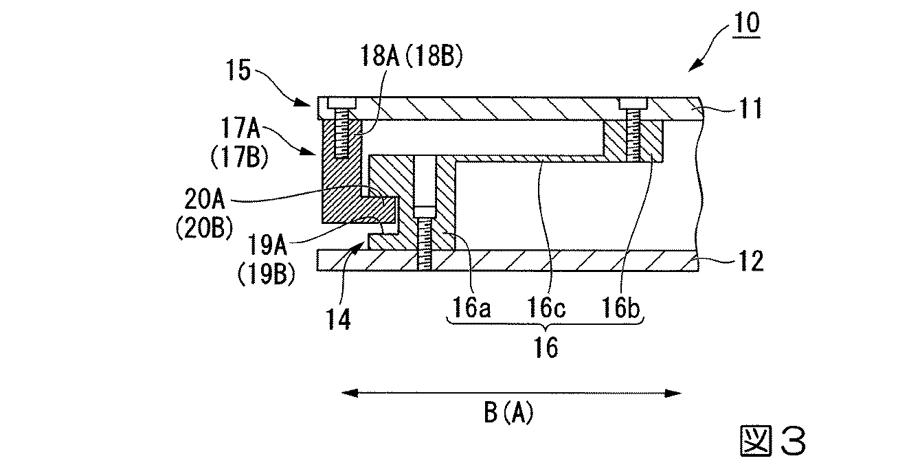
図3に示すように、連結部材16は、両ベース部材11、12に各別に固定された一対の固定基部16a、16bと、前記基準軸O2に直交する径方向に延在し、一対の固定基部16a、16bを連結する弾性変形部16cと、を備えている。各連結部材16における一対の固定基部16a、16bおよび弾性変形部16cは、前記周方向の大きさおよび位置が互いに同等となっている。
The support means 14 includes a connecting
As shown in FIG. 3, the connecting
一対の固定基部16a、16bは、前記周方向に長い直方体状に形成されるとともに、前記径方向に互いにずらされて配置されている。一対の固定基部16a、16bのうち、下ベース部材12に固定された下固定基部16aは、上ベース部材11に固定された上固定基部16bよりも前記径方向の外側に位置している。下固定基部16aと上ベース部材11との間、および上固定基部16bと下ベース部材12との間には、上下方向の隙間が各別に設けられている。下固定基部16aは、上下方向および前記径方向の各大きさが上固定基部16bより大きくなっている。
The pair of fixed
なお下固定基部16aは、下ベース部材12にボルトにより固定されている。前記ボルトは、下固定基部16aに形成された挿通孔に上方から差し込まれた後、下ベース部材12に形成されたねじ孔にねじ込まれ、前記ボルトの頭部は、下固定基部16aの前記挿通孔内に収容されている。
また上固定基部16bも、上ベース部材11にボルトにより固定されている。前記ボルトは、上ベース部材11に形成された挿通孔に上方から差し込まれた後、上固定基部16bに形成されたねじ孔にねじ込まれ、前記ボルトの頭部は、上ベース部材11の前記挿通孔内に収容されている。
The lower
The upper fixed
弾性変形部16cにおける前記径方向の両端部は、一対の固定基部16a、16bに各別に接続され、弾性変形部16cにおける前記径方向の外端部が下固定基部16aに接続され、弾性変形部16cにおける前記径方向の内端部が上固定基部16bに接続されている。弾性変形部16cは、下固定基部16aにおいて前記径方向の内側を向く内面の上端と、上固定基部16bにおいて前記径方向の外側を向く外面の下端と、を連結している。
Both ends in the radial direction of the
弾性変形部16cにおける前記周方向の曲げ剛性は、弾性変形部16cにおける上下方向の曲げ剛性よりも大きくなっており、弾性変形部16cは、一対の固定基部16a、16bと一体の板状に形成されている。弾性変形部16cの表裏面は、上下方向に直交し、前記径方向および前記周方向の両方向に沿って延在している。弾性変形部16cの前記径方向に沿った大きさは、一対の固定基部16a、16bそれぞれの前記径方向に沿った大きさよりも大きくなっている。弾性変形部16cの上下方向に沿った大きさは、一対の固定基部16a、16bそれぞれの上下方向に沿った大きさよりも小さくなっている。弾性変形部16cは、一対の固定基部16a、16bと一体に成形されたいわゆるフレキシャー(板ばね)である。
The bending rigidity in the circumferential direction of the
ここで図2に示すように、連結部材16は、前記基準軸O2を左右方向Bに挟むように左右一対設けられるとともに、前記基準軸O2を前後方向Aに挟むように前後一対設けられている。左右一対の連結部材16は、前記基準軸O2を基準として左右方向Bに対称に配置され、前後方向Aの位置が同等となっている。前後一対の連結部材16は、前記基準軸O2を基準として前後方向Aに対称に配置され、左右方向Bの位置が同等となっている。
Here, as shown in FIG. 2, a pair of connecting
規制手段15は、両ベース部材11、12の左右方向Bの相対的な変位を規制する第1規制手段17Aと、両ベース部材11、12の前後方向Aの相対的な変位を規制する第2規制手段17Bと、を備えている。
第1規制手段17Aは、左右一対の連結部材16を左右方向Bの外側から挟み込む左右一対の第1係合部材18Aを備えている。図3に示すように、第1係合部材18Aは、左右一対の連結部材16それぞれにおける下固定基部16aに左右方向Bの外側から対向し、近接または当接している。第1係合部材18Aは、前後方向Aに延在する直方体状に形成され、上ベース部材11に固定されている。第1係合部材18Aと下ベース部材12との間には、上下方向の隙間があいている。
The restricting means 15 is a first restricting
The first restricting
第1係合部材18Aには、当該第1係合部材18Aに左右方向Bに対向する下固定基部16aに、左右方向Bの外側に向けて開口するように形成された第1凹溝部19A内に進入する第1爪部20Aが、左右方向Bの内側に向けて突設されている。第1爪部20Aは、第1係合部材18Aと一体に成形され、第1係合部材18Aの下端部から左右方向Bの内側に向けて突設されている。第1爪部20Aは、第1凹溝部19A内において上側にずらされて配置されており、第1爪部20Aの上面と第1凹溝部19Aの内壁面との上下方向の間隔は、第1爪部20Aの下面と第1凹溝部19Aの内壁面との上下方向の間隔よりも狭くなっている。なお第1凹溝部19Aは、前後方向Aの両側に開口している。
In the
図2に示すように、第2規制手段17Bは、前後一対の連結部材16を前後方向Aの外側から挟み込む前後一対の第2係合部材18Bを備えている。図3に示すように、第2係合部材18Bは、前後一対の連結部材16それぞれにおける下固定基部16aに前後方向Aの外側から対向し、近接または当接している。第2係合部材18Bは、左右方向Bに延在する直方体状に形成され、上ベース部材11に固定されている。第2係合部材18Bと下ベース部材12との間には、上下方向の隙間があいている。
As shown in FIG. 2, the second restricting means 17 </ b> B includes a pair of front and rear second engaging members 18 </ b> B that sandwich the pair of front and rear connecting
第2係合部材18Bには、当該第2係合部材18Bに前後方向Aに対向する下固定基部16aに、前後方向Aの外側に向けて開口するように形成された第2凹溝部19B内に進入する第2爪部20Bが、前後方向Aの内側に向けて突設されている。第2爪部20Bは、第2係合部材18Bと一体に成形され、第2係合部材18Bの下端部から前後方向Aの内側に向けて突設されている。第2爪部20Bは、第2凹溝部19B内において上側にずらされて配置されており、第2爪部20Bの上面と第2凹溝部19Bの内壁面との上下方向の間隔は、第2爪部20Bの下面と第2凹溝部19Bの内壁面との上下方向の間隔よりも狭くなっている。なお第2凹溝部19Bは、左右方向Bの両側に開口している。
In the second engaging
なお、第1係合部材18Aおよび第2係合部材18Bは、上ベース部材11にボルトにより固定されている。前記ボルトは、上ベース部材11に形成された挿通孔に上方から差し込まれた後、各係合部材18A、18Bに形成されたねじ孔にねじ込まれ、前記ボルトの頭部は、上ベース部材11の前記挿通孔内に収容されている。
The first engaging
図2に示すように、荷重測定手段13は、前記周方向に同等の間隔をあけて4つ配置されている。荷重測定手段13は、前記基準軸O2を中心とする同一円周上に位置しており、前記周方向に隣り合う複数の連結部材16同士の間に配置されている。4つの荷重測定手段13は、前記平面視において上ベース部材11および下ベース部材12の4つの角部に対応して配置されている。
As shown in FIG. 2, four load measuring means 13 are arranged at equal intervals in the circumferential direction. The load measuring means 13 is located on the same circumference centered on the reference axis O2, and is disposed between the plurality of connecting
なお、4つの荷重測定手段13のうち、前後方向Aの一方側に位置する2つの荷重測定手段13同士は、前後方向Aの位置が同等であり、前後方向Aの他方側に位置する2つの荷重測定手段13同士も、前後方向Aの位置が同等である。前後方向Aの一方側に位置する荷重測定手段13と他方側に位置する荷重測定手段13とは、前後方向Aに距離L(以下、離間距離Lという)離間している。また、4つの荷重測定手段13のうち、左右方向Bの一方側に位置する2つの荷重測定手段13同士は、左右方向Bの位置が同等であり、左右方向Bの他方側に位置する2つの荷重測定手段13同士も、左右方向Bの位置が同等である。左右方向Bの一方側に位置する荷重測定手段13と他方側に位置する荷重測定手段13とは、左右方向Bに前記離間距離L離間している。 Of the four load measuring means 13, the two load measuring means 13 located on one side in the front-rear direction A have the same position in the front-rear direction A, and the two load measuring means 13 located on the other side in the front-rear direction A The load measuring means 13 are also at the same position in the front-rear direction A. The load measuring means 13 located on one side in the front-rear direction A and the load measuring means 13 located on the other side are separated by a distance L (hereinafter referred to as a separation distance L) in the front-rear direction A. Of the four load measuring means 13, the two load measuring means 13 located on one side in the left-right direction B have the same position in the left-right direction B, and the two load measuring means 13 located on the other side in the left-right direction B The positions of the load measuring means 13 in the left-right direction B are also equal. The load measuring means 13 located on one side in the left-right direction B and the load measuring means 13 located on the other side are separated by the separation distance L in the left-right direction B.
図1に示すように、荷重測定手段13は、例えばひずみゲージ式のロードセルにより構成され、図示しない制御部に測定結果を送出する。荷重測定手段13の着力部13aは、当該荷重測定手段13の上端部を構成しており、上ベース部材11の下面に当接している。なお上ベース部材11自体の荷重は、前記支持手段14により受け止められており、荷重測定手段13には、上ベース部材11自体の荷重が実質的に作用していない。
As shown in FIG. 1, the load measuring means 13 is constituted by, for example, a strain gauge type load cell, and sends a measurement result to a control unit (not shown). The
前記タイヤ試験装置10を用いたタイヤ試験方法では、例えば航空機用タイヤ等の重荷重用タイヤTにおいて路面から左右方向Bに横力が入力された状態を再現し、荷重測定手段13の測定結果に基づいてタイヤTの重心の左右方向Bおよび前後方向Aの各位置を検出する。なお航空機用タイヤでは、例えば航空機が離着陸するときや、航空機が地上で旋回移動をするとき等に横力が入力される。
In the tire testing method using the
このタイヤ試験方法では、上ベース部材11上にタイヤTを押し当てた状態で下ベース部材12を左右方向Bに移動させた後、荷重測定手段13に作用する荷重を測定する測定工程を実施する。この工程ではまず、タイヤ保持装置2によりタイヤTをタイヤ試験装置10の上ベース部材11上に押し当て、例えばタイヤTに最大で約784kN(80tf)程度の荷重を付与する。すると、連結部材16の弾性変形部16cが上下方向に曲げ変形して連結部材16が上下方向に弾性変形することで上ベース部材11が下方に変位し、タイヤTからの荷重が、上ベース部材11を介して荷重測定手段13に作用する。
In this tire test method, after the
そして、規制手段15により両ベース部材11、12の前後方向Aおよび左右方向Bの相対的な変位が規制された状態で、移動装置3の前記移動台部3aを左右方向Bに移動させることで、下ベース部材12を上ベース部材11とともに左右方向Bに移動させる。
ここで第1規制手段17Aは、第1係合部材18Aと、当該第1係合部材18Aに左右方向Bに対向する下固定基部16aと、が係合し合うことで、両ベース部材11、12の左右方向Bの相対的な変位を規制する。例えば、上ベース部材11の下ベース部材12に対する左右方向Bの一方側への変位は、左右一対の第1係合部材18Aのうち、左右方向Bの他方側に位置するものが下固定基部16aに係合することで規制される。
また第2規制手段17Bは、第2係合部材18Bと、当該第2係合部材18Bに前後方向Aに対向する下固定基部16aと、が係合し合うことで、両ベース部材11、12の前後方向Aの相対的な変位を規制する。例えば、上ベース部材11の下ベース部材12に対する前後方向Aの一方側への変位は、前後一対の第2係合部材18Bのうち、前後方向Aの他方側に位置するものが下固定基部16aに係合することで規制される。
Then, by moving the moving
Here, the first restricting
Further, the second restricting means 17B is configured so that the second engaging
以上のように下ベース部材12を移動させた後、荷重測定手段13に作用する荷重を測定することで、測定工程が終了する。
なおその後、タイヤTの上ベース部材11上への押し当てを解除すると、連結部材16の弾性復元力により上ベース部材11が上方に復元変位する。
After the
After that, when the pressing of the tire T onto the
測定工程の後、荷重測定手段13により測定された測定結果に基づいて、タイヤTの重心の左右方向Bおよび前後方向Aの各位置を検出する検出工程を実施する。本実施形態では、例えばタイヤTの重心の左右方向Bおよび前後方向Aの各位置として、タイヤTの重心の前記基準軸O2からの左右方向Bおよび前後方向Aへの各位置ずれ量を、下記(1)式および下記(2)式を用いて算出する。なお各式中のLは、離間距離Lを意味する。 After the measurement process, a detection process for detecting each position of the center of gravity of the tire T in the left-right direction B and the front-rear direction A based on the measurement result measured by the load measuring means 13 is performed. In the present embodiment, for example, as the respective positions in the left-right direction B and the front-rear direction A of the center of gravity of the tire T, the positional deviation amounts of the center of gravity of the tire T in the left-right direction B and the front-rear direction A from the reference axis O2 are as follows. It calculates using (1) Formula and following (2) Formula. In addition, L in each formula means the separation distance L.
以上説明したように、本実施形態に係るタイヤ試験装置10およびタイヤ試験方法によれば、連結部材16が上下方向に弾性変形することで、支持手段14が上ベース部材11を下方に変位させるので、測定工程の際にタイヤTからの荷重を荷重測定手段13に作用させつつ、上ベース部材11自体の荷重を支持手段14に受け止めさせることが可能になり、上ベース部材11自体の荷重が荷重測定手段13に作用するのを抑えることができる。
また規制手段15が、両ベース部材11、12の前後方向Aおよび左右方向Bの相対的な移動を規制するので、測定工程の際、規制手段15により両ベース部材11、12の前後方向Aおよび左右方向Bの相対的な変位が規制された状態で、下ベース部材12を上ベース部材11とともに左右方向Bまたは前後方向Aに移動させることが可能になり、荷重測定手段13に前後力や横力が加えられるのを抑えることができる。
以上より、測定工程の際、タイヤTからの荷重を荷重測定手段13により精度良く測定することが可能になり、高精度な試験をすることができる。
As described above, according to the
Further, since the restricting
As described above, during the measurement process, the load from the tire T can be measured with high accuracy by the load measuring means 13, and a highly accurate test can be performed.
また、弾性変形部16cにおける前記周方向の曲げ剛性が、弾性変形部16cにおける上下方向の曲げ剛性よりも大きいので、タイヤTが上ベース部材11上に押し当てられたときに、連結部材16の弾性変形部16cを、前記周方向への変形を抑えつつ上下方向に曲げ変形させ易くすることができる。これにより、連結部材16が前記周方向に複数配置されていることと相俟って、上ベース部材11を安定して下方に変位させることが可能になり、荷重測定手段13によりタイヤTからの荷重をより精度良く測定することができる。
さらに弾性変形部16cが、一対の固定基部16a、16bと一体の板状に形成されているので、上ベース部材11を更に安定して下方に変位させることが可能になり、荷重測定手段13により上下方向の荷重をより一層精度良く測定することができる。
Further, since the bending rigidity in the circumferential direction of the
Further, since the
また連結部材16が、前記基準軸O2を左右方向Bに挟むように左右一対設けられるとともに、前記基準軸O2を前後方向Aに挟むように前後一対設けられているので、上ベース部材11を前記基準軸O2の左右方向Bの両側および前後方向Aの両側から各別に支持することができる。これにより、上ベース部材11が、前後方向Aに延びる前後ロール軸や左右方向Bに延びる左右ロール軸回りに揺動するのを抑えることが可能になり、更に高精度な試験をすることができる。
In addition, a pair of connecting
なお本実施形態のように、弾性変形部16cが、一対の固定基部16a、16bと一体の板状に形成されている場合には、連結部材16が、前記基準軸O2を前後方向Aに挟むように前後一対設けられることで、両ベース部材11、12が前後方向Aに相対的に変位しようとしたときに、前後一対の連結部材16に作用する前後力を、これらの連結部材16の各弾性変形部16cに受け止めさせ易くすることができる。さらにこの場合、連結部材16が、前記基準軸O2を左右方向Bに挟むように左右一対設けられることで、両ベース部材11、12が左右方向Bに相対的に変位しようとしたときに、左右一対の連結部材16に作用する横力を、これらの連結部材16の各弾性変形部16cに受け止めさせ易くすることができる。
以上のように、前後一対の連結部材16に作用する前後力、および左右一対の連結部材16に作用する横力を、これらの連結部材16の各弾性変形部16cに受け止めさせ易くすることができるので、両ベース部材11、12が前後方向Aや左右方向Bに相対的に変位するのを確実に抑制することができる。
When the elastically deforming
As described above, the longitudinal force acting on the pair of front and rear connecting
また第1係合部材18Aと、当該第1係合部材18Aに左右方向Bに対向する連結部材16の下固定基部16aと、が係合し合うことで、第1規制手段17Aが、両ベース部材11、12の左右方向Bの相対的な変位を規制するので、例えば、第1係合部材18Aに係合する部材を別途設ける場合に比べて、当該タイヤ試験装置10の構造の簡素化を図ることができる。
また第1係合部材18Aと、当該第1係合部材18Aに左右方向Bに対向する連結部材16の下固定基部16aと、が係合し合うことで、第1規制手段17Aが、両ベース部材11、12の左右方向Bの相対的な変位を規制するので、例えば第1係合部材が、連結部材16のうちの弾性変形部16cに係合する場合に比べて、両ベース部材11、12の左右方向Bの相対的な変位を確実に規制しつつ、上ベース部材11を下方に確実に安定して変位させることが可能になり、荷重測定手段13により上下方向の荷重を確実に一層精度良く測定することができる。
さらに第1爪部20Aが、前記第1凹溝部19A内に進入しているので、上ベース部材11の前後ロール軸回りの揺動を、第1爪部20Aを第1凹溝部19Aの内壁面に当接させることで規制することが可能になり、更に一層高精度な試験をすることができる。
Further, the first restricting
Further, the first restricting
Further, since the
また第2係合部材18Bと、当該第2係合部材18Bに前後方向Aに対向する連結部材16の下固定基部16aと、が係合し合うことで、第2規制手段17Bが、両ベース部材11、12の前後方向Aの相対的な変位を規制するので、例えば、第2係合部材18Bに係合する部材を別途設ける場合に比べて、当該タイヤ試験装置10の構造の簡素化を図ることができる。
また第2係合部材18Bと、当該第2係合部材18Bに前後方向Aに対向する連結部材16の下固定基部16aと、が係合し合うことで、第2規制手段17Bが、両ベース部材11、12の前後方向Aの相対的な変位を規制するので、例えば第2係合部材が、連結部材16のうちの弾性変形部16cに係合する場合に比べて、両ベース部材11、12の前後方向Aの相対的な変位を確実に規制しつつ、上ベース部材11を下方に確実に安定して変位させることが可能になり、荷重測定手段13により上下方向の荷重を確実に一層精度良く測定することができる。
さらに第2爪部20Bが、前記第2凹溝部19B内に進入しているので、上ベース部材11の左右ロール軸回りの揺動を、第2爪部20Bを第2凹溝部19Bの内壁面に当接させることで規制することが可能になり、更に一層高精度な試験をすることができる。
In addition, the second engaging
In addition, the second engaging
Further, since the
なお、本発明の技術的範囲は前記実施形態に限定されるものではなく、本発明の趣旨を逸脱しない範囲において種々の変更を加えることが可能である。
例えば、第1爪部20Aおよび第2爪部20Bはなくてもよい。
The technical scope of the present invention is not limited to the above embodiment, and various modifications can be made without departing from the spirit of the present invention.
For example, the
また、規制手段15は前記実施形態に示したものに限られない。例えば、両ベース部材に、互いに前後方向または左右方向に係合し合う係合部材が各別に、連結部材とは別体で設けられ、これらの係合部材が互いに係合し合うことで、両ベース部材の前後方向または左右方向の相対的な変位を規制してもよい。
Further, the restricting
また前記実施形態では、連結部材16が、前記基準軸O2を左右方向Bに挟むように左右一対設けられるとともに、前記基準軸O2を前後方向Aに挟むように前後一対設けられているものとしたが、これに限られない。例えば、前記基準軸を、前後方向および左右方向の両方向に傾斜する方向に挟むように一対設けられていてもよい。
In the embodiment, a pair of connecting
また前記実施形態では、弾性変形部16cが、一対の固定基部16a、16bと一体の板状に形成されているものとしたが、これに限られない。例えば、弾性変形部が、一対の固定基部とボルトにより各別に固定されていてもよい。
さらに前記実施形態では、連結部材16が前記周方向に複数配置されているものとしたが、これに限られない。
Moreover, in the said embodiment, although the
Furthermore, in the said embodiment, although the
また前記実施形態では、荷重測定手段13は4つであるものとしたが、1つや2つや3つでもよく、5つ以上であってもよい。
さらに前記実施形態では、測定工程の際、下ベース部材12を左右方向Bに移動させたが、所望する試験結果に応じて前後方向に移動させることも可能である。
In the above embodiment, the number of load measuring means 13 is four, but may be one, two, three, or five or more.
Furthermore, in the said embodiment, although the
その他、本発明の趣旨に逸脱しない範囲で、前記実施形態における構成要素を周知の構成要素に置き換えることは適宜可能であり、また、前記した変形例を適宜組み合わせてもよい。 In addition, it is possible to appropriately replace the constituent elements in the embodiment with known constituent elements without departing from the spirit of the present invention, and the above-described modified examples may be appropriately combined.
A 前後方向
B 左右方向
O2 基準軸
T タイヤ
10 タイヤ試験装置
11 上ベース部材
12 下ベース部材
13 荷重測定手段
14 支持手段
15 規制手段
16 連結部材
16a、16b 固定基部
16c 弾性変形部
17A 第1規制手段
17B 第2規制手段
18A 第1係合部材
18B 第2係合部材
19A 第1凹溝部
19B 第2凹溝部
20A 第1爪部
20B 第2爪部
A Front-rear direction B Left-right direction O2 Reference
Claims (9)
これらの両ベース部材の間に配置され、上方から作用する荷重を測定する荷重測定手段と、を備え、前記上ベース部材上にタイヤが押し当てられるタイヤ試験装置であって、
前記上ベース部材を下方に変位可能に支持する支持手段と、
前記両ベース部材の前記タイヤの前後方向および左右方向の相対的な変位を規制する規制手段と、を備え、
前記支持手段は、前記両ベース部材を連結し上下方向に弾性変形可能な連結部材を備えていることを特徴とするタイヤ試験装置。 An upper base member and a lower base member arranged at intervals in the vertical direction;
A load measuring means arranged between these two base members and measuring a load acting from above, and a tire testing device in which a tire is pressed onto the upper base member,
Support means for supporting the upper base member so as to be displaceable downward;
Restriction means for restricting relative displacement in the front-rear direction and the left-right direction of the tire of the base members,
The tire testing apparatus according to claim 1, wherein the supporting means includes a connecting member that connects the base members and is elastically deformable in the vertical direction.
前記連結部材は、前記上ベース部材において前記タイヤが押し当てられる部分を通り上下方向に延在する基準軸回りに沿う周方向に複数配置され、
前記連結部材は、前記両ベース部材に各別に固定された一対の固定基部と、前記基準軸に直交する径方向に延在し、前記一対の固定基部を連結する弾性変形部と、を備え、
前記弾性変形部における前記周方向の曲げ剛性は、前記弾性変形部における上下方向の曲げ剛性よりも大きくなっていることを特徴とするタイヤ試験装置。 The tire testing device according to claim 1,
A plurality of the connecting members are arranged in a circumferential direction along a reference axis extending in the up-down direction through a portion to which the tire is pressed in the upper base member,
The connecting member includes a pair of fixed bases separately fixed to the base members, and an elastic deformation part extending in a radial direction perpendicular to the reference axis and connecting the pair of fixed bases,
The tire test apparatus according to claim 1, wherein the bending rigidity in the circumferential direction of the elastic deformation portion is larger than the bending rigidity in the vertical direction of the elastic deformation portion.
前記弾性変形部は、前記一対の固定基部と一体の板状に形成されていることを特徴とするタイヤ試験装置。 The tire testing device according to claim 2,
The tire testing device, wherein the elastic deformation portion is formed in a plate shape integral with the pair of fixed base portions.
前記連結部材は、前記基準軸を左右方向に挟むように左右一対設けられるとともに、前記基準軸を前後方向に挟むように前後一対設けられていることを特徴とするタイヤ試験装置。 The tire testing device according to claim 2 or 3,
A pair of front and rear connecting members are provided so as to sandwich the reference axis in the left-right direction, and a pair of front and rear are provided so as to sandwich the reference axis in the front-rear direction.
前記規制手段は、前記両ベース部材の左右方向の相対的な変位を規制する第1規制手段を備え、
前記第1規制手段は、左右一対の前記連結部材を左右方向の外側から挟み込み、前記固定基部に左右方向の外側から対向する左右一対の第1係合部材を備え、
前記第1規制手段は、前記第1係合部材と、当該第1係合部材に左右方向に対向する前記固定基部と、が係合し合うことで、前記両ベース部材の左右方向の相対的な変位を規制することを特徴とするタイヤ試験装置。 The tire testing device according to claim 4,
The restricting means includes first restricting means for restricting relative displacement in the left-right direction of the base members,
The first restricting means includes a pair of left and right first engaging members that sandwich the pair of left and right connecting members from the outside in the left and right direction and face the fixed base from the outside in the left and right direction,
The first restricting means is configured such that the first engaging member and the fixed base portion that opposes the first engaging member in the left-right direction are engaged with each other, whereby the both base members are relatively relative to each other in the left-right direction. Tire testing device characterized by restricting the displacement.
前記第1係合部材には、当該第1係合部材に左右方向に対向する前記固定基部に、左右方向の外側に向けて開口するように形成された第1凹溝部内に進入する第1爪部が、左右方向の内側に向けて突設されていることを特徴とするタイヤ試験装置。 The tire testing device according to claim 5,
The first engagement member enters the first concave groove formed so as to open toward the outer side in the left-right direction at the fixed base facing the first engagement member in the left-right direction. A tire testing device, wherein the claw portion is provided so as to project inward in the left-right direction.
前記規制手段は、前記両ベース部材の前後方向の相対的な変位を規制する第2規制手段を備え、
前記第2規制手段は、前後一対の前記連結部材を前後方向の外側から挟み込み、前記固定基部に前後方向の外側から対向する前後一対の第2係合部材を備え、
前記第2規制手段は、前記第2係合部材と、当該第2係合部材に前後方向に対向する前記固定基部と、が係合し合うことで、前記両ベース部材の前後方向の相対的な変位を規制することを特徴とするタイヤ試験装置。 The tire testing device according to any one of claims 4 to 6,
The restricting means includes second restricting means for restricting relative displacement in the front-rear direction of the base members,
The second restricting means includes a pair of front and rear second engaging members that sandwich the pair of front and rear connecting members from the outside in the front-rear direction and face the fixed base from the outside in the front-rear direction,
The second restricting means is configured such that the second engaging member and the fixed base portion facing the second engaging member in the front-rear direction are engaged with each other, so that the base members in the front-rear direction are relative to each other. Tire testing device characterized by restricting the displacement.
前記第2係合部材には、当該第2係合部材に前後方向に対向する前記固定基部に、前後方向の外側に向けて開口するように形成された第2凹溝部内に進入する第2爪部が、前後方向の内側に向けて突設されていることを特徴とするタイヤ試験装置。 The tire testing device according to claim 7,
The second engagement member enters the second concave groove portion formed to open toward the outer side in the front-rear direction on the fixed base portion facing the second engagement member in the front-rear direction. A tire testing apparatus, wherein the claw portion is provided so as to project inward in the front-rear direction.
前記上ベース部材上に前記タイヤを押し当てた状態で前記下ベース部材を左右方向または前後方向に移動させた後、前記荷重測定手段に作用する荷重を測定する測定工程を有することを特徴とするタイヤ試験方法。 A tire test method using the tire test apparatus according to claim 1,
It has a measuring step of measuring a load acting on the load measuring means after moving the lower base member in the left-right direction or the front-rear direction with the tire pressed against the upper base member. Tire test method.
Priority Applications (1)
| Application Number | Priority Date | Filing Date | Title |
|---|---|---|---|
| JP2013084234A JP5745566B2 (en) | 2013-04-12 | 2013-04-12 | Tire testing apparatus and tire testing method |
Applications Claiming Priority (1)
| Application Number | Priority Date | Filing Date | Title |
|---|---|---|---|
| JP2013084234A JP5745566B2 (en) | 2013-04-12 | 2013-04-12 | Tire testing apparatus and tire testing method |
Publications (2)
| Publication Number | Publication Date |
|---|---|
| JP2014206464A true JP2014206464A (en) | 2014-10-30 |
| JP5745566B2 JP5745566B2 (en) | 2015-07-08 |
Family
ID=52120113
Family Applications (1)
| Application Number | Title | Priority Date | Filing Date |
|---|---|---|---|
| JP2013084234A Expired - Fee Related JP5745566B2 (en) | 2013-04-12 | 2013-04-12 | Tire testing apparatus and tire testing method |
Country Status (1)
| Country | Link |
|---|---|
| JP (1) | JP5745566B2 (en) |
Cited By (5)
| Publication number | Priority date | Publication date | Assignee | Title |
|---|---|---|---|---|
| CN104729862A (en) * | 2015-03-19 | 2015-06-24 | 南京航空航天大学 | Tire stiffness testing device |
| JP2018031688A (en) * | 2016-08-25 | 2018-03-01 | 株式会社エー・アンド・デイ | Grounding force measurement device and method of tire |
| JP2018031689A (en) * | 2016-08-25 | 2018-03-01 | 株式会社エー・アンド・デイ | Grounding force measuring method of tire |
| JP2018031690A (en) * | 2016-08-25 | 2018-03-01 | 株式会社エー・アンド・デイ | Slip ratio measurement device and method |
| US10082446B2 (en) * | 2015-10-01 | 2018-09-25 | A&D Company, Limited | Tire testing apparatus |
Citations (4)
| Publication number | Priority date | Publication date | Assignee | Title |
|---|---|---|---|---|
| JPS59180447A (en) * | 1983-03-31 | 1984-10-13 | Agency Of Ind Science & Technol | Motor-vehicle simulator |
| JPH0894498A (en) * | 1994-07-27 | 1996-04-12 | Nissan Motor Co Ltd | Compliance tester |
| JPH1038791A (en) * | 1996-07-26 | 1998-02-13 | Hinode Suido Kiki Kk | Apparatus for measuring coefficient of friction of surface construction |
| JP2008151509A (en) * | 2006-12-14 | 2008-07-03 | Iyasaka Seiki Kk | Air floating device for vehicle inspection |
-
2013
- 2013-04-12 JP JP2013084234A patent/JP5745566B2/en not_active Expired - Fee Related
Patent Citations (4)
| Publication number | Priority date | Publication date | Assignee | Title |
|---|---|---|---|---|
| JPS59180447A (en) * | 1983-03-31 | 1984-10-13 | Agency Of Ind Science & Technol | Motor-vehicle simulator |
| JPH0894498A (en) * | 1994-07-27 | 1996-04-12 | Nissan Motor Co Ltd | Compliance tester |
| JPH1038791A (en) * | 1996-07-26 | 1998-02-13 | Hinode Suido Kiki Kk | Apparatus for measuring coefficient of friction of surface construction |
| JP2008151509A (en) * | 2006-12-14 | 2008-07-03 | Iyasaka Seiki Kk | Air floating device for vehicle inspection |
Cited By (5)
| Publication number | Priority date | Publication date | Assignee | Title |
|---|---|---|---|---|
| CN104729862A (en) * | 2015-03-19 | 2015-06-24 | 南京航空航天大学 | Tire stiffness testing device |
| US10082446B2 (en) * | 2015-10-01 | 2018-09-25 | A&D Company, Limited | Tire testing apparatus |
| JP2018031688A (en) * | 2016-08-25 | 2018-03-01 | 株式会社エー・アンド・デイ | Grounding force measurement device and method of tire |
| JP2018031689A (en) * | 2016-08-25 | 2018-03-01 | 株式会社エー・アンド・デイ | Grounding force measuring method of tire |
| JP2018031690A (en) * | 2016-08-25 | 2018-03-01 | 株式会社エー・アンド・デイ | Slip ratio measurement device and method |
Also Published As
| Publication number | Publication date |
|---|---|
| JP5745566B2 (en) | 2015-07-08 |
Similar Documents
| Publication | Publication Date | Title |
|---|---|---|
| JP5745566B2 (en) | Tire testing apparatus and tire testing method | |
| CN102576189B (en) | For two location that can be substantially parallel to each other object between the method and apparatus of active wedge error compensation | |
| WO2017183684A1 (en) | Aircraft fuselage assembly jig and method for using same | |
| CN104400284A (en) | Positioning device and buckling positioning method of longitudinal beam | |
| CN104582867A (en) | Bending press having an angle-measuring device and method for determining the bending angle | |
| US9573279B2 (en) | Clamp apparatus for industrial robot | |
| EP2853316B1 (en) | Upper mould and lower mould temporary joint method | |
| CN102435275B (en) | Sensor used for dynamic weighing | |
| CN210533642U (en) | Normal and tangential contact rigidity measuring device of joint surface | |
| EP3702727B1 (en) | Axial gap measurement device and measurement method for ball screw device, and method for producing ball screw device, vehicle and mechanical device | |
| US8984995B2 (en) | Device for the fast exchange of nuts in a lathe plate | |
| US10226834B2 (en) | Welding gun alignment detection device | |
| JP2015222216A (en) | Force sensor testing device | |
| CN204881405U (en) | Testing equipment of comprehensive testing VKP product hole site | |
| JP5467622B1 (en) | Wedge-shaped jack device | |
| JP2014142302A (en) | Mounting device | |
| JP2018009816A (en) | Tire rigidity test method | |
| CN202350893U (en) | Sensor for dynamic weighing | |
| CN215338925U (en) | Coupling rigidity test bed | |
| JP2010005694A (en) | Positioning device for exchanging die | |
| CN104949597A (en) | Automobile floor crossbeam reinforcing member detection device | |
| CN204422322U (en) | For the simple and easy centering stationary installation of test block of concrete compression creep test | |
| CN203863655U (en) | Base plate for automobile floor beam reinforcer test tool | |
| US20130333480A1 (en) | Test apparatus, compliance mechanism, and related method | |
| CN102950408B (en) | Draw gear box positioning device and positioning and assembling method |
Legal Events
| Date | Code | Title | Description |
|---|---|---|---|
| A131 | Notification of reasons for refusal |
Free format text: JAPANESE INTERMEDIATE CODE: A131 Effective date: 20141209 |
|
| A521 | Written amendment |
Free format text: JAPANESE INTERMEDIATE CODE: A523 Effective date: 20150120 |
|
| TRDD | Decision of grant or rejection written | ||
| A01 | Written decision to grant a patent or to grant a registration (utility model) |
Free format text: JAPANESE INTERMEDIATE CODE: A01 Effective date: 20150407 |
|
| A61 | First payment of annual fees (during grant procedure) |
Free format text: JAPANESE INTERMEDIATE CODE: A61 Effective date: 20150501 |
|
| R150 | Certificate of patent or registration of utility model |
Ref document number: 5745566 Country of ref document: JP Free format text: JAPANESE INTERMEDIATE CODE: R150 |
|
| R250 | Receipt of annual fees |
Free format text: JAPANESE INTERMEDIATE CODE: R250 |
|
| R250 | Receipt of annual fees |
Free format text: JAPANESE INTERMEDIATE CODE: R250 |
|
| R250 | Receipt of annual fees |
Free format text: JAPANESE INTERMEDIATE CODE: R250 |
|
| LAPS | Cancellation because of no payment of annual fees |