JP2014198985A - Structure and method for connecting building unit - Google Patents

Structure and method for connecting building unit Download PDF

Info

Publication number
JP2014198985A
JP2014198985A JP2013118312A JP2013118312A JP2014198985A JP 2014198985 A JP2014198985 A JP 2014198985A JP 2013118312 A JP2013118312 A JP 2013118312A JP 2013118312 A JP2013118312 A JP 2013118312A JP 2014198985 A JP2014198985 A JP 2014198985A
Authority
JP
Japan
Prior art keywords
building unit
building
unit
column
lower structure
Prior art date
Legal status (The legal status is an assumption and is not a legal conclusion. Google has not performed a legal analysis and makes no representation as to the accuracy of the status listed.)
Granted
Application number
JP2013118312A
Other languages
Japanese (ja)
Other versions
JP6235245B2 (en
Inventor
光浩 林
Mitsuhiro Hayashi
光浩 林
Current Assignee (The listed assignees may be inaccurate. Google has not performed a legal analysis and makes no representation or warranty as to the accuracy of the list.)
Sekisui Chemical Co Ltd
Original Assignee
Sekisui Chemical Co Ltd
Priority date (The priority date is an assumption and is not a legal conclusion. Google has not performed a legal analysis and makes no representation as to the accuracy of the date listed.)
Filing date
Publication date
Application filed by Sekisui Chemical Co Ltd filed Critical Sekisui Chemical Co Ltd
Priority to JP2013118312A priority Critical patent/JP6235245B2/en
Publication of JP2014198985A publication Critical patent/JP2014198985A/en
Application granted granted Critical
Publication of JP6235245B2 publication Critical patent/JP6235245B2/en
Expired - Fee Related legal-status Critical Current
Anticipated expiration legal-status Critical

Links

Images

Abstract

PROBLEM TO BE SOLVED: To reliably bind a column to a lower structure even in the case of the column of a building unit in any position with respect to an outer hull of a unit building.SOLUTION: In a structure for connecting building units 30 and 40, the building units 30 and 40 stacked on a foundation 20 as a lower structure are connected to the foundation 20 as the lower structure. Columns 31 and 41 of the building units 30 and 40 and the foundation 20 as the lower structure are bound together by a connection member 50 that is inserted vertically through hollow parts of the columns 31 and 41 of the building units 30 and 40.

Description

本発明は建物ユニットの連結構造及び方法に関する。   The present invention relates to a building unit connection structure and method.

建物ユニットの連結構造として、特許文献1に記載のものがある。
この建物ユニットの連結構造は、図7(A)に示す如く、ユニット建物1の平面視で、該ユニット建物1の外郭に囲まれた内部で隣接する建物ユニット2(1階建物ユニット2Aと2階建物ユニット2B)の柱間隙部A(4個の建物ユニット2のコーナー柱3が互いに相近接して形成する間隙部)において、長尺の図7(B)に示す如くのワイヤ4を用いている。ワイヤ4の下端部は基礎5に埋め込まれ(又は基礎5に埋設されたホールインアンカーに螺入され、ワイヤ4の上端部は2階建物ユニット2Bのコーナー柱3の上端に緊結される。
There exists a thing of patent document 1 as a connection structure of a building unit.
As shown in FIG. 7 (A), this building unit connection structure includes a building unit 2 (first floor building units 2A and 2A) adjacent to each other inside the unit building 1 in plan view. In the column gap A of the floor building unit 2B) (the gap formed by the corner columns 3 of the four building units 2 close to each other), a long wire 4 as shown in FIG. 7B is used. Yes. The lower end portion of the wire 4 is embedded in the foundation 5 (or screwed into a hole-in anchor embedded in the foundation 5, and the upper end portion of the wire 4 is fastened to the upper end of the corner column 3 of the second-floor building unit 2B.

このとき、ワイヤ4の先端に取付けたボルト4Aを相隣接する2階建物ユニット2Bにおける柱3の上エンドプレートに架け渡された固定プレート6の下方から上方に挿通し、固定プレート6の上方に突き出たボルト4Aに螺着されるナット4Bを該固定プレート6に締結し、ワイヤ4の張力を調整することとしている。このワイヤ4により、1階建物ユニット2Aと2階建物ユニット2Bを基礎5に対して一度に連結するものである。   At this time, the bolt 4A attached to the tip of the wire 4 is inserted upward from below the fixed plate 6 spanning the upper end plate of the pillar 3 in the adjacent second-floor building unit 2B, and above the fixed plate 6. A nut 4B that is screwed onto the protruding bolt 4A is fastened to the fixed plate 6 to adjust the tension of the wire 4. The wire 4 connects the first floor building unit 2A and the second floor building unit 2B to the foundation 5 at a time.

特開2000-129795JP2000-129795

しかしながら、該特許文献1に記載のワイヤ4は、ユニット建物1の外郭に囲まれた内部で隣接する建物ユニット2の柱間隙部Aにおいて用いることができるに過ぎず、ユニット建物1の外郭に位置する建物ユニット2の柱間隙部B又は出隅部Cで用いることができない。   However, the wire 4 described in Patent Document 1 can only be used in the column gap portion A of the adjacent building unit 2 surrounded by the outer wall of the unit building 1, and is positioned in the outer wall of the unit building 1. It cannot be used in the column gap part B or the protruding corner part C of the building unit 2.

即ち、ユニット建物1の外郭に位置する建物ユニット2の柱間隙部Bにワイヤ4を採用しようとしても、ワイヤ4が当該柱間隙部Bに装填される防水材や気密材と干渉し、結果として当該ワイヤ4を設置できない。   That is, even if it is going to employ | adopt the wire 4 for the column gap part B of the building unit 2 located in the outline of the unit building 1, the wire 4 interferes with the waterproof material and airtight material with which the said column gap part B is loaded, As a result The wire 4 cannot be installed.

また、ユニット建物1の外郭に位置する建物ユニット2の出隅部Cでは、ワイヤ4の先端のボルト4Aに螺着したナット4Bが締結されることとなる固定プレート6を相隣接する2階建物ユニット2Bの上エンドプレートに架け渡すことができず、結果として当該ワイヤ4を設置できない。   In addition, at the corner C of the building unit 2 located outside the unit building 1, the second floor building adjacent to the fixing plate 6 to which the nut 4B screwed to the bolt 4A at the tip of the wire 4 is fastened. The unit 2B cannot be bridged over the upper end plate, and as a result, the wire 4 cannot be installed.

また、特許文献1に記載のワイヤ4は、その下端部を基礎5に埋め込み、又は基礎5に埋設したホールインアンカーに螺入する必要があり、施工性及び作業性が悪い。   Moreover, the wire 4 described in Patent Document 1 needs to be embedded in the foundation 5 or screwed into a hole-in anchor embedded in the foundation 5, and the workability and workability are poor.

本発明の課題は、ユニット建物の外郭に対していかなる位置にある建物ユニットの柱であっても、当該柱を下部構造体に確実に緊結することにある。   An object of the present invention is to securely bond a pillar of a building unit at any position with respect to the outline of the unit building to the lower structure.

本発明の他の課題は、ユニット建物の外郭に対していかなる位置にある建物ユニットの柱であっても、当該柱を下部構造体に確実に緊結するとともに、その施工性及び作業性を向上することにある。   Another object of the present invention is to securely fix the column to the lower structure and improve the workability and workability of the column of the building unit at any position with respect to the outline of the unit building. There is.

請求項1に係る発明は、下部構造体の上に積層された建物ユニットを、該下部構造体に連結する建物ユニットの連結構造において、建物ユニットの柱の中空部に上下に貫通するように挿通された連結材により、建物ユニットの柱と下部構造体とを緊結するようにしたものである。   According to a first aspect of the present invention, in a building unit connection structure in which a building unit laminated on a lower structure is connected to the lower structure, the building unit is inserted so as to penetrate vertically through a hollow portion of a column of the building unit. By using the connected material, the column of the building unit and the lower structure are tightly coupled.

請求項2に係る発明は、請求項1に係る発明において更に、前記建物ユニットの柱の中空部に挿通された連結材の下端部を下部構造体に連結するとともに、該連結材の上端部を建物ユニットにおける上記柱の上端に連結するようにしたものである。   According to a second aspect of the present invention, in the first aspect of the invention, the lower end portion of the connecting member inserted into the hollow portion of the pillar of the building unit is connected to the lower structure, and the upper end portion of the connecting member is It connects with the upper end of the said pillar in a building unit.

請求項3に係る発明は、請求項2に係る発明において更に、前記下部構造体がフランジとウエブを備えた形鋼を有してなり、連結材の下端部が該下部構造体における形鋼のフランジに設けた連結孔に挿通されて該フランジの下面に係止されてなるようにしたものである。   According to a third aspect of the present invention, in the second aspect of the invention, the lower structure further includes a shape steel having a flange and a web, and a lower end portion of the connecting material is a shape steel of the lower structure. It is inserted into a connecting hole provided in the flange and locked to the lower surface of the flange.

請求項4に係る発明は、請求項3に係る発明において更に、前記下部構造体がH形鋼を横置きした基礎からなり、連結材の下端部が該基礎におけるH形鋼のフランジに設けた連結孔に挿通されて該フランジの下面に係止されてなるようにしたものである。   The invention according to claim 4 is the invention according to claim 3, wherein the lower structure is composed of a foundation in which H-shaped steel is horizontally placed, and the lower end portion of the connecting material is provided on the flange of the H-shaped steel in the foundation. It is inserted into the connecting hole and locked to the lower surface of the flange.

請求項5に係る発明は、請求項3に係る発明において更に、前記下部構造体がC形鋼からなる梁を有する下階建物ユニットからなり、連結材の下端部が該下階建物ユニットの梁におけるC形鋼のフランジに設けた連結孔に挿通されて該フランジの下面に係止されてなるようにしたものである。   The invention according to claim 5 is the invention according to claim 3, wherein the lower structure is composed of a lower-floor building unit having a beam made of C-shaped steel, and the lower end portion of the connecting material is a beam of the lower-floor building unit. Is inserted into a connecting hole provided in the flange of the C-shaped steel and is engaged with the lower surface of the flange.

請求項6に係る発明は、請求項1〜5のいずれかに係る発明において更に、前記連結材がワイヤからなるようにしたものである。   The invention according to claim 6 is the invention according to any one of claims 1 to 5, wherein the connecting member is made of a wire.

請求項7に係る発明は、請求項1〜6のいずれかに係る発明において更に、前記下部構造体の上に、水平方向に相隣接する複数の建物ユニットを積層し、それらの相隣接する建物ユニットの各上部がジョイント板を介して互いに接合されるようにしたものである。   The invention according to claim 7 is the invention according to any one of claims 1 to 6, further comprising: stacking a plurality of building units adjacent to each other in the horizontal direction on the lower structure, and building adjacent to each other. Each upper part of the unit is joined to each other through a joint plate.

請求項8に係る発明は、請求項7に係る発明において更に、前記相隣接する建物ユニットの各上部が、ボルトによりジョイント板に締結されてなるようにしたものである。   The invention according to claim 8 is the invention according to claim 7, wherein each upper part of the adjacent building units is fastened to the joint plate by a bolt.

請求項9に係る発明は、請求項7に係る発明において更に、前記相隣接する建物ユニットの各上部が備える孔に、ジョイント板に設けたピンを係合してなるようにしたものである。   According to a ninth aspect of the present invention, in the seventh aspect of the invention, a pin provided on the joint plate is engaged with a hole provided in each upper part of the adjacent building units.

請求項10に係る発明は、請求項7に係る発明において更に、前記相隣接する建物ユニットの各柱の上端に設けたエンドプレートが備える挿通孔のそれぞれに隙間なく挿通された前記連結材のそれぞれが、ジョイント板に設けた孔に係入されてなるようにしたものである。   The invention according to claim 10 is the invention according to claim 7, respectively, wherein each of the connecting members inserted through the insertion holes provided in the end plates provided at the upper ends of the columns of the adjacent building units without gaps. Is inserted into a hole provided in the joint plate.

請求項11に係る発明は、下部構造体の上に積層された建物ユニットを、該下部構造体に連結する建物ユニットの連結方法において、建物ユニットの柱の中空部に連結材を挿通し、この連結材により建物ユニットの柱と下部構造体とを緊結するようにしたものである。   According to an eleventh aspect of the present invention, there is provided a method for connecting a building unit that is stacked on a lower structure to a lower part of the building unit. The column of the building unit and the lower structure are tightly connected by a connecting material.

請求項12に係る発明は、請求項11に係る発明において更に、前記建物ユニットの柱の中空部に挿通された連結材の下端部を下部構造体に連結するとともに、該連結材の上端部を建物ユニットにおける上記柱の上端に連結するようにしたものである。   The invention according to claim 12 is the invention according to claim 11, wherein the lower end portion of the connecting member inserted through the hollow portion of the pillar of the building unit is connected to the lower structure, and the upper end portion of the connecting member is It connects with the upper end of the said pillar in a building unit.

請求項13に係る発明は、請求項11又は12に係る発明において更に、前記下部構造体の上に複数の相隣接する建物ユニットを積層し、それらの相隣接する建物ユニットの各上部がジョイント板を介して互いに接合されるようにしたものである。   The invention according to claim 13 is the invention according to claim 11 or 12, further comprising: stacking a plurality of adjacent building units on the lower structure, wherein each upper part of the adjacent building units is a joint plate. It is made to join mutually via.

(請求項1、11)
(a)建物ユニットの柱の中空部に上下に貫通するように挿通された連結材により、建物ユニットの柱と下部構造体とを緊結する。従って、連結材は、ユニット建物の外郭に囲まれた内部に位置して相隣接する4個の建物ユニットの各柱、ユニット建物の外郭に位置して相隣接する2個の建物ユニットの各柱、又はユニット建物の外郭に位置する建物ユニットの出隅部の柱等、ユニット建物の外郭に対していかなる位置にある建物ユニットの柱であっても、当該柱を下部構造体に確実に緊結することができる。
(Claims 1 and 11)
(a) The column of the building unit and the lower structure are fastened by a connecting member that is inserted so as to penetrate vertically through the hollow portion of the column of the building unit. Therefore, the connecting material is a column of four building units located adjacent to each other inside the unit building and a column of two building units located adjacent to the unit building. The column of the building unit located at any position with respect to the outline of the unit building, such as a column at the corner of the building unit located outside the unit building, is securely bonded to the lower structure. be able to.

(請求項2、12)
(b)前記建物ユニットの柱の中空部に挿通された連結材の下端部を下部構造体に連結するとともに、該連結材の上端部を建物ユニットにおける上記柱の上端に連結する。従って、連結材により建物ユニットの柱と下部構造体とを確実に緊結することができる。
(Claims 2 and 12)
(b) The lower end portion of the connecting member inserted into the hollow portion of the column of the building unit is connected to the lower structure, and the upper end portion of the connecting member is connected to the upper end of the column in the building unit. Therefore, the pillar of the building unit and the lower structure can be securely bonded by the connecting material.

(請求項3)
(c)前記下部構造体がフランジとウエブを備えた形鋼を有してなり、連結材の下端部が該下部構造体における形鋼のフランジに設けた連結孔に挿通されて該フランジの下面に係止される。従って、連結材の下端部は下部構造体に埋込んだり、螺入することなく、下部構造体における形鋼のフランジの下面に係止されて該下部構造体に簡易に連結され、その施工性及び作業性を向上できる。
(Claim 3)
(c) The lower structure has a shape steel provided with a flange and a web, and the lower end portion of the connecting material is inserted into a connection hole provided in the flange of the shape steel in the lower structure, and the lower surface of the flange It is locked to. Therefore, the lower end portion of the connecting material is easily embedded in the lower structure by being locked to the lower surface of the flange of the shape steel in the lower structure without being embedded or screwed into the lower structure. And workability can be improved.

(請求項4)
(d)前記下部構造体がH形鋼を横置きした基礎からなり、連結材の下端部が該基礎におけるH形鋼のフランジに設けた連結孔に挿通されて該フランジの下面に係止される。従って、連結材の下端部は下部構造体たる基礎におけるH形鋼のフランジの下面に係止されて該下部構造体に簡易に連結され、その施工性及び作業性を向上できる。
(Claim 4)
(d) The lower structure is composed of a foundation on which H-shaped steel is horizontally placed, and the lower end portion of the coupling material is inserted into a coupling hole provided in the flange of the H-shaped steel in the foundation and locked to the lower surface of the flange. The Therefore, the lower end portion of the connecting member is locked to the lower surface of the flange of the H-shaped steel in the foundation as the lower structure and is easily connected to the lower structure, thereby improving the workability and workability.

(請求項5)
(e)前記下部構造体がC形鋼からなる梁を有する下階建物ユニットからなり、連結材の下端部が該下階建物ユニットの梁におけるC形鋼のフランジに設けた連結孔に挿通されて該フランジの下面に係止される。従って、連結材の下端部は下部構造体たる下階建物ユニットの梁におけるC形鋼のフランジの下面に係止されて該下部構造体に簡易に連結され、その施工性及び作業性を向上できる
(Claim 5)
(e) The lower structure comprises a lower-floor building unit having a beam made of C-shaped steel, and the lower end portion of the connecting material is inserted into a connecting hole provided in a flange of the C-shaped steel in the beam of the lower-floor building unit. And is locked to the lower surface of the flange. Therefore, the lower end portion of the connecting member is locked to the lower surface of the flange of the C-shaped steel in the beam of the lower-floor building unit as the lower structure, and is easily connected to the lower structure, thereby improving the workability and workability.

(請求項6)
(f)前記連結材がワイヤからなるものとすることにより、柱の中空部に挿通される施工前段階で、該連結材として長尺の鉄筋棒を用い場合に比して、連結材となるワイヤを巻線状態で取扱いでき、その取扱性を向上できる。
(Claim 6)
(f) When the connecting material is made of a wire, the connecting material becomes a connecting material in the pre-construction stage inserted through the hollow portion of the column as compared with a case where a long reinforcing bar is used as the connecting material. The wire can be handled in a wound state, and the handling property can be improved.

(請求項7、13)
(g)前記下部構造体の上に、水平方向に相隣接する複数の建物ユニットを積層し、それらの相隣接する建物ユニットの各上部がジョイント板を介して互いに接合される。従って、ユニット建物の外郭に対していかなる位置にある建物ユニットの柱であっても、当該柱を下部構造体に確実に緊結することに加え、当該ユニット建物を構成するように水平方向にて相隣接する複数の建物ユニットを互いに確実に接合できる。
(Claims 7 and 13)
(g) A plurality of building units adjacent to each other in the horizontal direction are stacked on the lower structure, and upper portions of the adjacent building units are joined to each other via a joint plate. Therefore, even if the pillar of the building unit is located at any position with respect to the outline of the unit building, in addition to securely fastening the pillar to the lower structure, it is compatible in the horizontal direction so as to constitute the unit building. A plurality of adjacent building units can be reliably joined to each other.

(請求項8)
(h)前記相隣接する建物ユニットの各上部が、ボルトによりジョイント板に締結される。従って、ジョイント板とボルトを用いることにより、水平方向にて相隣接する複数の建物ユニットを互いに簡易かつ確実に接合できる。
(Claim 8)
(h) The upper portions of the adjacent building units are fastened to the joint plate by bolts. Therefore, by using the joint plate and the bolt, a plurality of building units adjacent to each other in the horizontal direction can be easily and reliably joined to each other.

(請求項9)
(i)前記相隣接する建物ユニットの各上部が備える孔に、ジョイント板に設けたピンを係合する。従って、ピン付ジョイント板を用いることにより、水平方向にて相隣接する複数の建物ユニットを互いに簡易かつ確実に接合できる。
(Claim 9)
(i) A pin provided on the joint plate is engaged with a hole provided in each upper part of the adjacent building unit. Therefore, by using a joint plate with pins, a plurality of building units adjacent in the horizontal direction can be easily and reliably joined to each other.

(請求項10)
(j)前記相隣接する建物ユニットの各柱の上端に設けたエンドプレートが備える挿通孔のそれぞれに隙間なく挿通された前記連結材のそれぞれが、ジョイント板に設けた孔に係入される。従って、ジョイント板を用い、かつ連結材を用いることにより、水平方向にて相隣接する複数の建物ユニットを互いに簡易かつ確実に接合できる。連結材が、柱の上部に設けたエンドプレートの挿通孔に対する嵌合精度と、ジョイント板に設けた孔に対する嵌合精度を高精度に設定することにより、複数の建物ユニットの水平方向における接合位置精度を向上できる。
(Claim 10)
(j) Each of the connecting members inserted through the insertion holes provided in the end plates provided at the upper ends of the columns of the building units adjacent to each other without gaps is inserted into the holes provided in the joint plate. Therefore, by using a joint plate and using a connecting member, a plurality of building units adjacent to each other in the horizontal direction can be easily and reliably joined to each other. The connecting position of multiple building units in the horizontal direction is set by setting the fitting accuracy to the insertion hole of the end plate provided in the upper part of the column and the fitting accuracy to the hole provided in the joint plate. Accuracy can be improved.

図1はユニット建物の一例を示す斜視図である。FIG. 1 is a perspective view showing an example of a unit building. 図2は実施例1の建物ユニットの連結構造を示す模式正面図である。FIG. 2 is a schematic front view illustrating a connecting structure of building units according to the first embodiment. 図3は建物ユニットの連結構造の連結過程を示す模式図である。FIG. 3 is a schematic diagram showing a connection process of the connection structure of building units. 図4は実施例2の建物ユニットの連結構造の連結過程を示す模式図である。FIG. 4 is a schematic diagram illustrating a connection process of the structure for connecting building units according to the second embodiment. 図5は実施例3の建物ユニットの連結構造を示す模式側面図である。FIG. 5 is a schematic side view illustrating a connecting structure of building units according to the third embodiment. 図6は建物ユニットの連結構造の連結過程を示す模式図である。FIG. 6 is a schematic diagram showing a connection process of the connection structure of building units. 図7は従来の建物ユニットの連結構造を示す模式図である。FIG. 7 is a schematic diagram showing a connecting structure of a conventional building unit. 図8はユニット建物において相隣接する建物ユニットの配置例を示す模式図である。FIG. 8 is a schematic diagram illustrating an arrangement example of building units adjacent to each other in a unit building. 図9はジョイント板を示す模式図である。FIG. 9 is a schematic view showing a joint plate. 図10は実施例4の建物ユニットの連結構造を示し、(A)は断面図、(B)は下階建物ユニットの上部接合構造を示す断面図、(C)は上階建物ユニットの上部接合構造を示す断面図である。FIG. 10: shows the connection structure of the building unit of Example 4, (A) is sectional drawing, (B) is sectional drawing which shows the upper joining structure of a lower-floor building unit, (C) is upper joining of an upper-floor building unit It is sectional drawing which shows a structure. 図11は建物ユニットの連結構造の連結過程を示す模式図である。FIG. 11 is a schematic diagram illustrating a connection process of a connection structure of building units. 図12は建物ユニットの連結構造の連結過程を示す模式図である。FIG. 12 is a schematic diagram showing a connection process of a building unit connection structure. 図13は建物ユニットの連結構造の連結過程を示す模式図である。FIG. 13 is a schematic diagram illustrating a connection process of the connection structure of building units. 図14は図11のXIV-XIV線に沿う矢視図である。FIG. 14 is a view taken along the line XIV-XIV in FIG. 図15は図12のXV-XV線に沿う矢視図である。FIG. 15 is a view taken along the line XV-XV in FIG. 図16は図12のXVI部を取出して示す模式斜視図である。FIG. 16 is a schematic perspective view showing the XVI portion of FIG. 図17は実施例5のジョイント板を示す模式斜視図である。FIG. 17 is a schematic perspective view showing the joint plate of the fifth embodiment. 図18は実施例6の建物ユニットの連結構造を示し、(A)は断面図、(B)は下階建物ユニットの上部接合構造を示す断面図、(C)は上階建物ユニットの上部接合構造を示す断面図である。18A and 18B show a connecting structure of building units of Example 6, wherein FIG. 18A is a cross-sectional view, FIG. 18B is a cross-sectional view showing an upper joint structure of a lower-floor building unit, and FIG. 18C is an upper joint of an upper-floor building unit. It is sectional drawing which shows a structure. 図19はジョイント板を示す模式図である。FIG. 19 is a schematic view showing a joint plate. 図20は図18のXX-XX線に沿う矢視図である。FIG. 20 is an arrow view along the line XX-XX in FIG.

(実施例1)(図1〜図3)
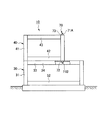
図1、図2に示したユニット建物10は、建築現場に設置した基礎20の上に、1階部分を構成する下階建物ユニット30と、2階部分を構成する上階建物ユニット40が順に積層されて構成される。
Example 1 (FIGS. 1 to 3)
The unit building 10 shown in FIGS. 1 and 2 has a lower floor building unit 30 constituting the first floor portion and an upper floor building unit 40 constituting the second floor portion in order on the foundation 20 installed on the construction site. It is constructed by stacking.

基礎20は、地盤Eに打設した複数本の鋼管杭21の上に、H形鋼22を横置き設置して構成される。H形鋼22が固定される鋼管杭21の上端は地盤Eから上方に突出していて、基礎20の外郭を形成するH形鋼22の外周に取着される化粧板23が鋼管杭21の上記突出部分を外部に対して隠している。   The foundation 20 is configured by horizontally installing an H-section steel 22 on a plurality of steel pipe piles 21 placed on the ground E. The upper end of the steel pipe pile 21 to which the H-shaped steel 22 is fixed protrudes upward from the ground E, and the decorative plate 23 attached to the outer periphery of the H-shaped steel 22 forming the outline of the foundation 20 is the above-described steel pipe pile 21. The protruding part is hidden from the outside.

下階建物ユニット30は、工場生産された軸組式の箱型骨組構造体であり、4個のコーナーに配置される中空角鋼管からなる柱31と、相隣る柱31の下端間に架け渡されるC形鋼からなる床梁32と、相隣る柱31の上端間に架け渡されるC形鋼からなる天井梁33とを有して構成される。   The lower-floor building unit 30 is a factory-produced frame-type box-type frame structure, and spans between columns 31 made of hollow square steel pipes arranged at four corners and lower ends of adjacent columns 31. It has a floor beam 32 made of C-shaped steel and a ceiling beam 33 made of C-shaped steel bridged between the upper ends of adjacent columns 31.

上階建物ユニット40も下階建物ユニット30と同様の箱型骨組構造体であり、柱41と床梁42と天井梁43とを有して構成される。   The upper-floor building unit 40 is also a box-type frame structure similar to the lower-floor building unit 30 and includes a column 41, a floor beam 42, and a ceiling beam 43.

実施例1のユニット建物10は、基礎20を本発明の下部構造体とするものであり、基礎20の上に積層された下階建物ユニット30と上階建物ユニット40を、該基礎20に以下の如くに連結する。即ち、ユニット建物10の平面視で同一位置にある下階建物ユニット30と上階建物ユニット40の同軸上にあって鉛直方向に一直線をなす柱31、41の中空部に上下に貫通するように挿通された線材状連結材50により、それらの下階建物ユニット30と上階建物ユニット40の柱31、41と基礎20とを緊結する。下階建物ユニット30と上階建物ユニット40は、各4個の柱31、41の全部を基礎20に緊結するものに限らず、各4個の柱31、41の任意の一部を基礎20に緊結するものでも良い。具体的には以下の通りである。   The unit building 10 of Example 1 uses the foundation 20 as the lower structure of the present invention. The lower-floor building unit 30 and the upper-floor building unit 40 stacked on the foundation 20 are connected to the foundation 20 as follows. Connect as follows. In other words, the lower building unit 30 and the upper building unit 40 located at the same position in plan view of the unit building 10 are coaxially arranged so as to vertically penetrate through the hollow portions of the columns 31 and 41 that are aligned in the vertical direction. The pillars 31 and 41 of the lower-floor building unit 30 and the upper-floor building unit 40 are connected to the foundation 20 by the inserted wire-like connecting member 50. The lower-floor building unit 30 and the upper-floor building unit 40 are not limited to those in which all the four pillars 31 and 41 are connected to the foundation 20, but any part of each of the four pillars 31 and 41 is the foundation 20. It may be tightly tied to. Specifically, it is as follows.

(1)基礎20の上に下階建物ユニット30と上階建物ユニット40を順に積層する。   (1) A lower-floor building unit 30 and an upper-floor building unit 40 are sequentially stacked on the foundation 20.

(2)連結材50を下階建物ユニット30と上階建物ユニット40の同軸上にあって一直線状をなす柱31、41の中空部に挿通する(図3(A))。   (2) The connecting member 50 is inserted through the hollow portions of the pillars 31 and 41 that are coaxial with the lower-floor building unit 30 and the upper-floor building unit 40 (FIG. 3A).

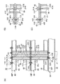
本実施例において、連結材50は長尺鉄筋棒51からなり、鉄筋棒51の上端部と下端部にボルト51A、51Bを備える。鉄筋棒51は、上階建物ユニット40における柱41の上下端に設けた上下のエンドプレート41E、41Eが備える各挿通孔41Hに挿通されるとともに、下階建物ユニット30における柱31の上下端に設けた上下のエンドプレート31E、31Eが備える各挿通孔31Hに挿通される。鉄筋棒51は、上階建物ユニット40と下階建物ユニット30の柱31、41の中空部に挿通されたとき、上端部のボルト51Aを柱41の上エンドプレート41Eが備える挿通孔41Hから上方に突出し、下端部のボルト51Bを柱31の下エンドプレート31Eが備える挿通孔31Hから下方に突出する。   In this embodiment, the connecting member 50 is composed of a long reinforcing bar 51 and includes bolts 51 </ b> A and 51 </ b> B at the upper end and the lower end of the reinforcing bar 51. The reinforcing bar 51 is inserted into the insertion holes 41H provided in the upper and lower end plates 41E and 41E provided at the upper and lower ends of the column 41 in the upper floor building unit 40, and at the upper and lower ends of the column 31 in the lower floor building unit 30. The upper and lower end plates 31E and 31E provided are inserted through the insertion holes 31H. When the reinforcing bar 51 is inserted into the hollow portions of the columns 31 and 41 of the upper-floor building unit 40 and the lower-floor building unit 30, the bolt 51A at the upper end is located above the insertion hole 41H provided in the upper end plate 41E of the column 41. The bottom end bolt 51B protrudes downward from the insertion hole 31H provided in the lower end plate 31E of the column 31.

(3)上階建物ユニット40と下階建物ユニット30の柱41、31の中空部に挿通された連結材50(鉄筋棒51)の下端部を下部構造体たる基礎20に連結するとともに、該連結材50(鉄筋棒51)の上端部を上階建物ユニット40における柱41の上端に設けた上エンドプレート41Eに連結する(図3(B))。   (3) The lower end portion of the connecting member 50 (rebar rod 51) inserted through the hollow portions of the columns 41 and 31 of the upper floor building unit 40 and the lower floor building unit 30 is connected to the foundation 20 as the lower structure, The upper end portion of the connecting member 50 (the reinforcing bar 51) is connected to the upper end plate 41E provided at the upper end of the column 41 in the upper floor building unit 40 (FIG. 3B).

本実施例において、基礎20は、図3(B)に示す如く、上下のフランジ22Fとウエブ22Wを備えたH形鋼22からなる。連結材50(鉄筋棒51)の下端部のボルト51Bは、下階建物ユニット30における柱31の下エンドプレート31Eが備える挿通孔31Hから下方に突出し、更に基礎20におけるH形鋼22の上フランジ22Fに設けた連結孔22Hに挿通され、該ボルト51Bに螺着されるナット52が該上フランジ22Fの下面に係止される。尚、H形鋼22は、上フランジ22Fと下フランジ22Fの間で、ウエブ22Wの両側に延在する補強用スチフナ22Sが設けられる(図3(B))。   In this embodiment, the foundation 20 is made of an H-section steel 22 having upper and lower flanges 22F and a web 22W, as shown in FIG. The bolt 51 </ b> B at the lower end of the connecting member 50 (rebar 51) protrudes downward from the insertion hole 31 </ b> H provided in the lower end plate 31 </ b> E of the column 31 in the lower floor building unit 30, and further the upper flange of the H-section steel 22 in the foundation 20. A nut 52 that is inserted into the connecting hole 22H provided in 22F and screwed to the bolt 51B is locked to the lower surface of the upper flange 22F. The H-shaped steel 22 is provided with reinforcing stiffeners 22S extending on both sides of the web 22W between the upper flange 22F and the lower flange 22F (FIG. 3B).

また、連結材50(鉄筋棒51)の上端部のボルト51Aは、上階建物ユニット40における柱41の上エンドプレート41Eが備える挿通孔41Hから上方に突出し、該ボルト51Aに螺着されるナット53が該上エンドプレート41Eの上面に締結される。   The bolt 51A at the upper end of the connecting member 50 (rebar 51) protrudes upward from the insertion hole 41H provided in the upper end plate 41E of the column 41 in the upper floor building unit 40, and is a nut that is screwed to the bolt 51A. 53 is fastened to the upper surface of the upper end plate 41E.

従って、鉄筋棒51の上端ボルト51A(又は下端ボルト51B)に対するナット53(又はナット52)の締付けによって鉄筋棒51に生ずる張力を調整し、下階建物ユニット30と上階建物ユニット40の柱31、41と基礎20とを緊結するものになる。   Therefore, the tension generated in the reinforcing bar 51 by tightening the nut 53 (or nut 52) to the upper end bolt 51A (or lower end bolt 51B) of the reinforcing bar 51 is adjusted, and the columns 31 of the lower floor building unit 30 and the upper floor building unit 40 are adjusted. , 41 and the foundation 20 are tightly coupled.

本実施例によれば以下の作用効果を奏する。
(a)建物ユニット30、40の柱31、41の中空部に挿通された連結材50(鉄筋棒51)により、建物ユニット30、40の柱31、41と下部構造体たる基礎20とを緊結する。従って、連結材50(鉄筋棒51)は、ユニット建物10の外郭に囲まれた内部に位置して相隣接する4個の下階建物ユニット30(又は上階建物ユニット40)の各柱31(又は41)、ユニット建物10の外郭に位置して相隣接する2個の下階建物ユニット30(又は上階建物ユニット40)の各柱31(又は41)、又はユニット建物10の外郭に位置する下階建物ユニット30(又は上階建物ユニット40)の出隅部の柱31(又は41)等、ユニット建物10の外郭に対していかなる位置にある建物ユニット30、40の柱31、41であっても、当該柱31、41を下部構造体たる基礎20に確実に緊結することができる。
According to the present embodiment, the following operational effects can be obtained.
(a) The pillars 31 and 41 of the building units 30 and 40 and the foundation 20 as the lower structure are tightly connected by the connecting member 50 (rebar bars 51) inserted into the hollow portions of the pillars 31 and 41 of the building units 30 and 40. To do. Accordingly, the connecting member 50 (the reinforcing bar 51) is positioned inside the unit building 10 and surrounded by the outer wall of the unit building 10, and the columns 31 (or the upper building units 40) of the four lower floor building units 30 (or upper floor building units 40) adjacent to each other. Or 41) each of the pillars 31 (or 41) of the two lower-floor building units 30 (or upper-floor building units 40) adjacent to each other located outside the unit building 10 or outside the unit building 10. The pillars 31 and 41 of the building units 30 and 40 located at any position with respect to the outline of the unit building 10 such as the pillar 31 (or 41) at the protruding corner of the lower-floor building unit 30 (or the upper-floor building unit 40). However, the pillars 31 and 41 can be securely bonded to the foundation 20 as the lower structure.

(b)前記建物ユニット30、40の柱31、41の中空部に挿通された連結材50(鉄筋棒51)の下端部を下部構造体たる基礎20に連結するとともに、該連結材50(鉄筋棒51)の上端部を建物ユニット30、40における上記柱31、41の上端に連結する。従って、連結材50(鉄筋棒51)により建物ユニット30、40の柱31、41と下部構造体たる基礎20とを確実に緊結することができる。   (b) While connecting the lower end part of the connection material 50 (rebar rod 51) inserted in the hollow part of the pillars 31 and 41 of the said building units 30 and 40 to the foundation 20 which is a lower structure, this connection material 50 (rebar) The upper end of the bar 51) is connected to the upper ends of the columns 31, 41 in the building units 30, 40. Therefore, the pillars 31 and 41 of the building units 30 and 40 and the foundation 20 that is the lower structure can be securely bonded by the connecting member 50 (the reinforcing bar 51).

(c)前記下部構造体たる基礎20がH形鋼22を横置きした基礎からなり、連結材50(鉄筋棒51)の下端部が該基礎20におけるH形鋼22のフランジ22Fに設けた連結孔22Hに挿通されて該フランジ22Fの下面に係止される。従って、連結材50(鉄筋棒51)の下端部は下部構造体たる基礎20に埋込んだり、螺入することなく、該基礎20におけるH形鋼22のフランジ22Fの下面に係止されて該下部構造体たる基礎20に簡易に連結され、その施工性及び作業性を向上できる。   (c) The foundation 20 as the lower structure is composed of a foundation in which an H-shaped steel 22 is placed horizontally, and the lower end portion of the connecting material 50 (the reinforcing bar 51) is connected to the flange 22F of the H-shaped steel 22 in the foundation 20. It is inserted into the hole 22H and locked to the lower surface of the flange 22F. Therefore, the lower end portion of the connecting member 50 (the reinforcing bar 51) is locked to the lower surface of the flange 22F of the H-shaped steel 22 in the foundation 20 without being embedded or screwed into the foundation 20 as the lower structure. It is simply connected to the foundation 20 which is a lower structure, and its workability and workability can be improved.

(実施例2)(図4)
実施例2のユニット建物10は、基礎20の上に実施例1におけると同様の下階建物ユニット30と上階建物ユニット40が順に積層されたものである。
(Example 2) (FIG. 4)
In the unit building 10 of the second embodiment, a lower-floor building unit 30 and an upper-floor building unit 40 similar to those in the first embodiment are sequentially stacked on the foundation 20.

実施例1のユニット建物10が実施例1におけると異なる点は、下階建物ユニット30を本発明の下部構造体とするものであり、上階建物ユニット40と下階建物ユニット30を以下の如くに連結する。即ち、上階建物ユニット40における柱41の中空部に上下に貫通するように挿通された線材状連結材60により、上階建物ユニット40の柱41と下階建物ユニット30とを緊結する。上階建物ユニット40は、各4個の柱41を下階建物ユニット30に緊結するものに限らず、各4個の柱41の任意の一部を下階建物ユニット30に緊結するものでも良い。具体的には以下の通りである。   The unit building 10 of the first embodiment is different from the first embodiment in that the lower-floor building unit 30 is the lower structure of the present invention, and the upper-floor building unit 40 and the lower-floor building unit 30 are as follows. Connect to That is, the pillar 41 of the upper floor building unit 40 and the lower floor building unit 30 are tightly connected by the wire-like connecting member 60 inserted so as to penetrate vertically through the hollow portion of the pillar 41 in the upper floor building unit 40. The upper floor building unit 40 is not limited to the structure in which each of the four pillars 41 is fastened to the lower floor building unit 30, and any part of the four pillars 41 may be fastened to the lower floor building unit 30. . Specifically, it is as follows.

(1)下階建物ユニット30の上に上階建物ユニット40を搭載する。   (1) The upper building unit 40 is mounted on the lower building unit 30.

(2)連結材60を上階建物ユニット40における柱41の中空部に挿通する(図4(A))。
本実施例において、連結材60は長尺ワイヤ61からなり、ワイヤ61の上端部にボルト61Aを連結して備え、ワイヤ61の下端部に吊り環61Bを連結して備える。ワイヤ61は、柱41の中空部に挿通されたとき、上端部のボルト61Aを柱41の上エンドプレート41Eに設けた挿通孔41Hから上方に突出し、下端部の吊り環61Bを柱41の中空部内で下エンドプレート41Eに近接する位置に留める。
(2) The connecting member 60 is inserted through the hollow portion of the column 41 in the upper floor building unit 40 (FIG. 4A).
In this embodiment, the connecting member 60 is made of a long wire 61, and includes a bolt 61 </ b> A connected to the upper end portion of the wire 61, and a suspension ring 61 </ b> B connected to the lower end portion of the wire 61. When the wire 61 is inserted into the hollow portion of the column 41, the upper end bolt 61 </ b> A protrudes upward from the insertion hole 41 </ b> H provided in the upper end plate 41 </ b> E of the column 41, and the suspension ring 61 </ b> B at the lower end portion is hollow in the column 41. The position is kept close to the lower end plate 41E within the section.

(3)上階建物ユニット40の柱41の中空部に挿通された連結材60(ワイヤ61)の下端部を下部構造体たる下階建物ユニット30に連結するとともに、該連結材60(ワイヤ61)の上端部を上階建物ユニット40における柱41の上端に設けた上エンドプレート41Eに連結する(図4(B))。   (3) The lower end of the connecting member 60 (wire 61) inserted through the hollow portion of the column 41 of the upper floor building unit 40 is connected to the lower floor building unit 30 as the lower structure, and the connecting member 60 (wire 61). ) Is connected to an upper end plate 41E provided at the upper end of the column 41 in the upper floor building unit 40 (FIG. 4B).

本実施例において、下階建物ユニット30は柱31の上エンドプレート31Eの上面にフック62を取付けられて備える。下階建物ユニット30の上に上階建物ユニット40が積層されたとき、柱31に備えた上記フック62は、上階建物ユニット30における柱41の下エンドプレート41Eに設けた挿通孔41Hから柱41の中空部内で該下エンドプレート41E近くまで挿入される。そこで、上階建物ユニット40の柱41の中空部内の下エンドプレート41Eに近接する位置まで挿通された連結材60(ワイヤ61)の下端部の吊り環61Bが、上記フック62に係入され得るものになる。   In this embodiment, the lower floor building unit 30 includes a hook 62 attached to the upper surface of the upper end plate 31E of the column 31. When the upper-floor building unit 40 is stacked on the lower-floor building unit 30, the hook 62 provided in the pillar 31 extends from the insertion hole 41 </ b> H provided in the lower end plate 41 </ b> E of the pillar 41 in the upper-floor building unit 30. In the hollow part of 41, it inserts to this lower end plate 41E vicinity. Therefore, the suspension ring 61B at the lower end of the connecting member 60 (wire 61) inserted to a position close to the lower end plate 41E in the hollow portion of the column 41 of the upper floor building unit 40 can be engaged with the hook 62. Become a thing.

また、連結材60(ワイヤ61)の上端部のボルト61Aは、上階建物ユニット40における柱41の上エンドプレート41Eに設けた挿通孔41Hから上方に突出し、該ボルト61Aに螺着されるナット63が該上エンドプレート41Eの上面に締結される。   The bolt 61A at the upper end of the connecting member 60 (wire 61) protrudes upward from an insertion hole 41H provided in the upper end plate 41E of the column 41 in the upper floor building unit 40, and is a nut that is screwed to the bolt 61A. 63 is fastened to the upper surface of the upper end plate 41E.

従って、ワイヤ61の上端ボルト61Aに対するナット63の締付けによってワイヤ61に生ずる張力を調整し、上階建物ユニット40の柱41と下階建物ユニット30とを緊結するものになる。   Accordingly, the tension generated in the wire 61 by adjusting the nut 63 to the upper end bolt 61A of the wire 61 is adjusted, and the column 41 of the upper floor building unit 40 and the lower floor building unit 30 are tightly coupled.

本実施例によれば以下の作用効果を奏する。
(a)上階建物ユニット40の柱41の中空部に挿通された連結材60により、上階建物ユニット40の柱41と下部構造体としての下階建物ユニット30とを緊結する。従って、連結材60は、ユニット建物10の外郭に囲まれた内部に位置して相隣接する4個の上階建物ユニット40の各柱41、ユニット建物10の外郭に位置して相隣接する2個の上階建物ユニット40の各柱41、又はユニット建物10の外郭に位置する上階建物ユニット40の出隅部の柱41等、ユニット建物10の外郭に対していかなる位置にある上階建物ユニット40の柱41であっても、当該柱41を下部構造体としての下階建物ユニット30に確実に緊結することができる。
According to the present embodiment, the following operational effects can be obtained.
(a) The column 41 of the upper-floor building unit 40 and the lower-floor building unit 30 as the lower structure are tightly connected by the connecting member 60 inserted into the hollow portion of the column 41 of the upper-floor building unit 40. Accordingly, the connecting member 60 is located inside the unit building 10 and surrounded by the outer wall of each of the four upper-floor building units 40 adjacent to each other. The upper-floor building in any position with respect to the outer wall of the unit building 10 such as each column 41 of the individual upper-floor building unit 40 or the column 41 at the outer corner of the upper-floor building unit 40 located on the outer wall of the unit building 10 Even the column 41 of the unit 40 can be securely coupled to the lower-floor building unit 30 as the lower structure.

(b)前記上階建物ユニット40の柱41の中空部に挿通された連結材60の下端部を下部構造体としての下階建物ユニット30に連結するとともに、該連結材60の上端部を上階建物ユニット40における上記柱41の上端に連結する。従って、連結材60により上階建物ユニット40の柱41と下部構造体としての下階建物ユニット30とを確実に緊結することができる。   (b) The lower end portion of the connecting member 60 inserted into the hollow portion of the column 41 of the upper floor building unit 40 is connected to the lower floor building unit 30 as a lower structure, and the upper end portion of the connecting member 60 is It connects with the upper end of the column 41 in the floor building unit 40. Therefore, the column 41 of the upper floor building unit 40 and the lower floor building unit 30 as the lower structure can be securely bonded by the connecting member 60.

尚、本実施例では、上階建物ユニット40の柱41を連結材60によって下部構造体たる下階建物ユニット30における柱31の上エンドプレート31E(柱頭)に連結するものである。従って、この連結に伴い連結材60に生じる緊張力は上階建物ユニット40の柱41に作用し、下階建物ユニット30の柱31に作用するところがない。即ち、下階建物ユニット30の柱31における軸力の増加を招くことがない。   In this embodiment, the column 41 of the upper floor building unit 40 is connected to the upper end plate 31E (pillar head) of the column 31 in the lower floor building unit 30 as the lower structure by the connecting member 60. Therefore, the tension generated in the connecting member 60 due to this connection acts on the pillar 41 of the upper floor building unit 40 and does not act on the pillar 31 of the lower floor building unit 30. That is, the axial force in the pillar 31 of the lower floor building unit 30 is not increased.

(c)前記連結材60がワイヤ61からなるものとすることにより、柱41の中空部に挿通される施工前段階で、該連結材60として長尺の鉄筋棒を用いる場合に比して、連結材60となるワイヤ61を巻線状態で取扱いでき、その取扱性を向上できる。   (c) When the connecting member 60 is made of the wire 61, compared to a case where a long reinforcing bar is used as the connecting member 60 in the pre-construction stage inserted through the hollow portion of the column 41, The wire 61 to be the connecting material 60 can be handled in a wound state, and the handling property can be improved.

(実施例3)(図5、図6)
実施例3のユニット建物10は、基礎20の上に実施例1におけると同様の下階建物ユニット30と上階建物ユニット40が順に積層されたものである。
Example 3 (FIGS. 5 and 6)
In the unit building 10 of the third embodiment, a lower-floor building unit 30 and an upper-floor building unit 40 similar to those in the first embodiment are sequentially stacked on the foundation 20.

実施例3のユニット建物10が実施例1におけると異なる点は、ユニット建物10の側面視で下階建物ユニット30の水平方向長さを上階建物ユニット40の水平方向長さより長くし、下階建物ユニット30と上階建物ユニット40の水平方向の一端の柱31、41を同一水平方向位置に配置し、上階建物ユニット40の水平方向の他端の柱41を下階建物ユニット30の水平方向の他端の柱31より一定距離セットバック配置したものである。従って、上階建物ユニット40の水平方向の他端に位置する柱41が、下階建物ユニット30の水平方向に沿う天井梁33の中間部に搭載されるものになる。   The unit building 10 of the third embodiment is different from the first embodiment in that the horizontal length of the lower floor building unit 30 is longer than the horizontal length of the upper floor building unit 40 in the side view of the unit building 10, and the lower floor The pillars 31 and 41 at one end in the horizontal direction of the building unit 30 and the upper floor building unit 40 are arranged at the same horizontal position, and the pillar 41 at the other end in the horizontal direction of the upper floor building unit 40 is placed horizontally in the lower floor building unit 30. A setback is arranged at a fixed distance from the pillar 31 at the other end in the direction. Therefore, the pillar 41 located at the other horizontal end of the upper floor building unit 40 is mounted on the middle portion of the ceiling beam 33 along the horizontal direction of the lower floor building unit 30.

これにより、実施例3のユニット建物10にあっては、C形鋼を横置きした天井梁33を有する下階建物ユニット30を下部構造体とするものであり、上階建物ユニット40と下階建物ユニット30を以下の如くに連結する。即ち、上階建物ユニット40において上述の如くにセットバック配置した柱41の中空部に上下に貫通するように挿通された線材状連結材70により、上階建物ユニット40の柱41と下階建物ユニット30の天井梁33とを緊結する。具体的には以下の通りである。   Thereby, in the unit building 10 of Example 3, the lower-floor building unit 30 having the ceiling beam 33 in which the C-shaped steel is placed horizontally is used as the lower structure. The building units 30 are connected as follows. That is, the pillar 41 of the upper-floor building unit 40 and the lower-floor building are formed by the wire-like connecting member 70 inserted so as to penetrate vertically through the hollow portion of the pillar 41 set back arranged in the upper-floor building unit 40 as described above. The ceiling beam 33 of the unit 30 is connected. Specifically, it is as follows.

(1)下階建物ユニット30の上に上階建物ユニット40をセットバック配置する。   (1) The upper-floor building unit 40 is set back on the lower-floor building unit 30.

(2)連結材70を上階建物ユニット40における柱41の中空部に挿通する(図6(A))。
本実施例において、連結材70は長尺ワイヤ71からなり、ワイヤ71の上端部と下端部にボルト71A、71Bを連結して備える。ワイヤ71は、上階建物ユニット40の柱41の中空部に挿通されたとき、上端部のボルト71Aを柱41の上エンドプレート41Eに設けた挿通孔41Hから上方に突出し、下端部のボルト71Bを柱41の下エンドプレート41Eに設けた挿通孔41Hから下方に突出する。
(2) The connecting member 70 is inserted into the hollow portion of the column 41 in the upper floor building unit 40 (FIG. 6A).
In this embodiment, the connecting member 70 is composed of a long wire 71 and includes bolts 71 </ b> A and 71 </ b> B connected to the upper end portion and the lower end portion of the wire 71. When the wire 71 is inserted into the hollow portion of the column 41 of the upper-floor building unit 40, the bolt 71A at the upper end projects upward from the insertion hole 41H provided in the upper end plate 41E of the column 41, and the bolt 71B at the lower end. Projecting downward from an insertion hole 41H provided in the lower end plate 41E of the column 41.

(3)上階建物ユニット40の柱41の中空部に挿通された連結材70(ワイヤ71)の下端部を下部構造体たる下階建物ユニット30における天井梁33に連結するとともに、該連結材70(ワイヤ71)の上端部を上階建物ユニット40における柱41の上端に設けた上エンドプレート41Eに連結する(図6(B))。   (3) The lower end portion of the connecting member 70 (wire 71) inserted through the hollow portion of the column 41 of the upper floor building unit 40 is connected to the ceiling beam 33 in the lower floor building unit 30 as the lower structure, and the connecting member The upper end of 70 (wire 71) is connected to the upper end plate 41E provided at the upper end of the column 41 in the upper floor building unit 40 (FIG. 6B).

本実施例において、下階建物ユニット30の天井梁33は上下のフランジ34Fとウエブ34Wを備えたC形鋼34からなる。連結材70(ワイヤ71)の下端部のボルト71Bは、上階建物ユニット40における柱41の下エンドプレート41Eに設けた挿通孔41Hから下方に突出し、更に下階建物ユニット30における天井梁33の上フランジ34Fに設けた連結孔34Hに挿通され、該ボルト71Bに螺着されるナット72が該上フランジ34Fの下面に係止される。   In the present embodiment, the ceiling beam 33 of the lower floor building unit 30 is made of a C-shaped steel 34 provided with upper and lower flanges 34F and a web 34W. The bolt 71B at the lower end of the connecting member 70 (wire 71) protrudes downward from the insertion hole 41H provided in the lower end plate 41E of the column 41 in the upper floor building unit 40, and further the ceiling beam 33 in the lower floor building unit 30. A nut 72 that is inserted into a connecting hole 34H provided in the upper flange 34F and screwed to the bolt 71B is locked to the lower surface of the upper flange 34F.

また、連結材71(ワイヤ71)の上端部のボルト71Aは、上階建物ユニット40における柱41の上エンドプレート41Eに設けた挿通孔41Hから上方に突出し、該ボルト71Aに螺着されるナット73が該上エンドプレート41Eの上面に締結される。   The bolt 71A at the upper end of the connecting member 71 (wire 71) protrudes upward from the insertion hole 41H provided in the upper end plate 41E of the column 41 in the upper floor building unit 40, and is a nut that is screwed to the bolt 71A. 73 is fastened to the upper surface of the upper end plate 41E.

従って、ワイヤ71の上端ボルト71A(又は下端ボルト71B)に対するナット73(又は72)の締付けによってワイヤ71に生ずる張力を調整し、下階建物ユニット30の天井梁33と上階建物ユニット40の柱41とを緊結するものになる。   Accordingly, the tension generated in the wire 71 by adjusting the nut 73 (or 72) to the upper end bolt 71A (or lower end bolt 71B) of the wire 71 is adjusted, and the ceiling beam 33 of the lower building unit 30 and the column of the upper building unit 40 are adjusted. 41 will be tied.

本実施例によれば以下の作用効果を奏する。
(a)上階建物ユニット40の柱41の中空部に挿通された連結材70により、上階建物ユニット40の柱41と下部構造体としての下階建物ユニット30とを緊結する。従って、連結材70は、ユニット建物10の外郭に位置して相隣接する2個の上階建物ユニット40の各柱41、又はユニット建物10の外郭に位置する上階建物ユニット40の出隅部の各柱41等、ユニット建物10の外郭に対していかなる位置にある上階建物ユニット40の柱41であっても、当該柱41を下部構造体たる下階建物ユニット30に確実に緊結することができる。
According to the present embodiment, the following operational effects can be obtained.
(a) The connecting member 70 inserted through the hollow portion of the column 41 of the upper building unit 40 connects the column 41 of the upper building unit 40 and the lower building unit 30 as the lower structure. Therefore, the connecting member 70 is located on the outer wall of the unit building 10 and is adjacent to each of the columns 41 of the two upper floor building units 40, or the corner of the upper floor building unit 40 that is positioned on the outer wall of the unit building 10. Even if the column 41 of the upper-floor building unit 40 is located at any position with respect to the outline of the unit building 10, such as each of the columns 41, the column 41 is securely connected to the lower-floor building unit 30 that is the lower structure. Can do.

(b)前記上階建物ユニット40の柱41の中空部に挿通された連結材70の下端部を下部構造体としての下階建物ユニット30に連結するとともに、該連結材70の上端部を上階建物ユニット40における上記柱41の上端に連結する。従って、連結材70により上階建物ユニット40の柱41と下部構造体としての下階建物ユニット30とを確実に緊結することができる。   (b) The lower end portion of the connecting member 70 inserted through the hollow portion of the column 41 of the upper floor building unit 40 is connected to the lower floor building unit 30 as a lower structure, and the upper end portion of the connecting member 70 is It connects with the upper end of the column 41 in the floor building unit 40. Therefore, the pillars 41 of the upper-floor building unit 40 and the lower-floor building unit 30 as the lower structure can be securely bonded by the connecting member 70.

(c)前記下部構造体がC形鋼34を横置きした天井梁33を有する下階建物ユニット30からなり、連結材70の下端部が該下階建物ユニット30の天井梁33におけるC形鋼のフランジ34Fに設けた連結孔34Hに挿通されて該フランジ34Fの下面に係止される。従って、連結材70の下端部は下部構造体たる下階建物ユニット30の天井梁33に螺入することなく、該天井梁33におけるC形鋼34のフランジ34Fの下面に係止されて該下部構造体たる下階建物ユニット30に簡易に連結され、その施工性及び作業性を向上できる   (c) The lower structure includes a lower-floor building unit 30 having a ceiling beam 33 in which a C-shaped steel 34 is placed horizontally, and the lower end portion of the connecting member 70 is a C-shaped steel in the ceiling beam 33 of the lower-floor building unit 30. Is inserted into a connecting hole 34H provided in the flange 34F and locked to the lower surface of the flange 34F. Accordingly, the lower end portion of the connecting member 70 is engaged with the lower surface of the flange 34F of the C-shaped steel 34 in the ceiling beam 33 without being screwed into the ceiling beam 33 of the lower floor building unit 30 as the lower structure. It is easily connected to the lower-floor building unit 30 as a structure, and its workability and workability can be improved.

(d)前記連結材70がワイヤ71からなるものとすることにより、柱41の中空部に挿通される施工前段階で、該連結材70として長尺の鉄筋棒を用い場合に比して、連結材70となるワイヤ71を巻線状態で取扱いでき、その取扱性を向上できる。   (d) When the connecting member 70 is made of the wire 71, compared to the case where a long reinforcing bar is used as the connecting member 70 in the pre-construction stage inserted through the hollow portion of the column 41, The wire 71 which becomes the connecting material 70 can be handled in a wound state, and the handling property can be improved.

(実施例4)(図8〜図17)
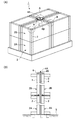
図8(A)は実施例1として図1に示したと同様のユニット建物10において、相隣接する下階建物ユニット30(又は上階建物ユニット40)の各上部がジョイント板110(図9(A))、又はジョイント板120(図9(B))を介して互いに接合されるものを示している。
Example 4 (FIGS. 8 to 17)
8A shows a unit building 10 similar to that shown in FIG. 1 as the first embodiment, but the upper parts of the adjacent lower-floor building units 30 (or upper-floor building units 40) are joint plates 110 (FIG. 9A). )), Or those joined to each other via the joint plate 120 (FIG. 9B).

ジョイント板110は、図9(A)に示す如く、ユニット建物10の外郭に囲まれた内部で、4個の下階建物ユニット30(又は上階建物ユニット40)の柱コーナー部が突き合わされ、相隣接する4個の建物ユニット30(又は40)の各柱31(又は41)の中空部に挿通される各連結材50(鉄筋棒51)が挿通し得る4個の挿通孔111と、それらの4個の建物ユニット30(又は40)の柱31(又は41)に接続されている天井梁33(又は43)とボルト締結されるための4個のボルト孔112を備える。   As shown in FIG. 9 (A), the joint plate 110 has four lower-floor building units 30 (or upper-floor building units 40) that face each other at the corners inside the unit building 10, and Four insertion holes 111 through which the connecting members 50 (rebar bars 51) inserted through the hollow portions of the columns 31 (or 41) of the four adjacent building units 30 (or 40) can be inserted, and Of the four building units 30 (or 40), and four bolt holes 112 to be bolted to the ceiling beam 33 (or 43) connected to the column 31 (or 41).

ジョイント板120は、図9(B)に示す如く、ユニット建物10の外郭に位置し、2個の建物ユニット30(又は40)の柱コーナー部が突き合わされ、相隣接する2個の建物ユニット30(又は40)の各柱31(又は41)の中空部に挿通される各連結材50(鉄筋棒51)が挿通し得る2個の挿通孔111と、それらの2個の建物ユニット30(又は40)の柱31(又は41)に接続されている天井梁33(又は43)とボルト締結されるための2個のボルト孔112を備える。   As shown in FIG. 9B, the joint plate 120 is located on the outer wall of the unit building 10, the two corners of the two building units 30 (or 40) are abutted, and the two adjacent building units 30. (Or 40) The two insertion holes 111 through which the connecting members 50 (rebar bars 51) inserted through the hollow portions of the pillars 31 (or 41) can be inserted, and the two building units 30 (or 40) two bolt holes 112 for bolting to the ceiling beam 33 (or 43) connected to the pillar 31 (or 41) of 40).

図8(B)は、相隣接する建物ユニット30(又は40)の各上部がジョイント板120(図9(B))又はジョイント板130(図9(C))を介して接合されるものを示している。ジョイント板120は、図8(A)におけるジョイント板120と同様である。   FIG. 8B shows an example in which each upper part of adjacent building units 30 (or 40) is joined via a joint plate 120 (FIG. 9B) or a joint plate 130 (FIG. 9C). Show. The joint plate 120 is the same as the joint plate 120 in FIG.

ジョイント板130は、図9(C)に示す如く、ユニット建物10の外郭に囲まれた内部で、2個の建物ユニット30(又は40)の柱コーナー部と、1個の建物ユニット30(又は40)の梁中間部が突き合わされ、相隣接するそれら2個の建物ユニット30(又は40)の各柱31(又は41)の中空部に挿通される各連結材50(鉄筋棒51)が挿通し得る2個の挿通孔111と、それらの2個の建物ユニット30(又は40)の柱31(又は41)に接続されている天井梁33(又は43)とボルト締結されるための2個のボルト孔112と、1個の建物ユニット30(又は40)の天井梁33(又は43)の梁中間部2カ所とボルト締結されるための2個のボルト孔113を備える。   As shown in FIG. 9C, the joint plate 130 is surrounded by the outer wall of the unit building 10, and the corners of the two building units 30 (or 40) and the one building unit 30 (or 40) The intermediate portions of the beams are abutted, and the connecting members 50 (rebar bars 51) inserted through the hollow portions of the columns 31 (or 41) of the two adjacent building units 30 (or 40) are inserted. Two insertion holes 111 that can be bolted to the ceiling beam 33 (or 43) connected to the pillar 31 (or 41) of the two building units 30 (or 40) Bolt holes 112 and two bolt holes 113 for bolting to two beam intermediate portions of the ceiling beam 33 (or 43) of one building unit 30 (or 40).

以下、ジョイント板110、120、130による建物ユニット30、40の連結構造について、ジョイント板110の使用例を代表として詳述する。   Hereinafter, the connection structure of the building units 30 and 40 by the joint plates 110, 120, and 130 will be described in detail as a representative example of the use of the joint plate 110.

即ち、図10に示す如く、ユニット建物10の外郭に囲まれた内部に位置して相隣接する4個の下階建物ユニット30(又は上階建物ユニット40)の各柱31(又は41)を前述の如くに連結材50(鉄筋棒51)により下部構造体たる基礎20に緊結するに先立ち、それらの4個の下階建物ユニット30(又は上階建物ユニット40)の上部の天井梁33(又は43)がジョイント板110を介して接合されるようにしたものである。具体的には以下の通りである。   That is, as shown in FIG. 10, the pillars 31 (or 41) of the four lower-floor building units 30 (or upper-floor building units 40) adjacent to each other located inside the unit building 10 are enclosed. As described above, before the connection member 50 (reinforcing bar 51) is fastened to the foundation 20 as the lower structure, the ceiling beams 33 (the upper beams 33 (or the upper building units 40) above the four lower building units 30 (or the upper building units 40) are connected. Or 43) is joined via the joint plate 110. Specifically, it is as follows.

(1)基礎20の上に相隣接する4個の下階建物ユニット30を設置する(図11)。   (1) Four adjacent lower floor building units 30 are installed on the foundation 20 (FIG. 11).

(2)4個の各下階建物ユニット30の相隣接する4個の柱31の上エンドプレート31E及び4個の天井梁33の上フランジ34Fの上面にジョイント板110が載置される。各天井梁33の上フランジ34Fに設けた挿通孔34Jに挿通したボルト113をジョイント板110の各ボルト孔112に挿通し、このボルト113及びナット114により、各天井梁33がジョイント板110に締結される(図12、図14)。   (2) The joint plate 110 is placed on the upper surfaces of the upper end plates 31E of the four columns 31 and the upper flanges 34F of the four ceiling beams 33 adjacent to each other of the four lower floor building units 30. Bolts 113 inserted into insertion holes 34J provided in the upper flanges 34F of the ceiling beams 33 are inserted into the bolt holes 112 of the joint plate 110, and the ceiling beams 33 are fastened to the joint plate 110 by the bolts 113 and nuts 114. (FIGS. 12 and 14).

(3)4個の上階建物ユニット40が対応する各下階建物ユニット30の上に載置される。各上階建物ユニット40の相隣接する4個の柱41の下エンドプレート41E及び4個の床梁42の下フランジの下面が、上述(2)のジョイント板110の上に載置される。このとき、ジョイント板110の上面に突設しているボルト113及びナット114は、上階建物ユニット40の床梁42の下フランジに設けられている大径孔42Hに挿通される(図12、図16)。   (3) Four upper-floor building units 40 are placed on the corresponding lower-floor building units 30. The lower end plates 41E of the four columns 41 adjacent to each other of the upper floor building units 40 and the lower surfaces of the lower flanges of the four floor beams 42 are placed on the joint plate 110 described in (2) above. At this time, the bolt 113 and the nut 114 protruding from the upper surface of the joint plate 110 are inserted into the large-diameter hole 42H provided in the lower flange of the floor beam 42 of the upper floor building unit 40 (FIG. 12, FIG. 16).

(4)4個の各上階建物ユニット40の相隣接する4個の柱41の上エンドプレート41E及び4個の天井梁43の上フランジ44Fの上面にジョイント板110が載置される。各天井梁43の上フランジ44Fに設けた挿通孔44Jに挿通したボルト115をジョイント板110の各ボルト孔112に挿通し、このボルト115及びナット116により、各天井梁43がジョイント板110に締結される(図12、図15)。   (4) The joint plate 110 is placed on the upper surfaces of the upper end plates 41E of the four columns 41 and the upper flanges 44F of the four ceiling beams 43 adjacent to each other of the four upper floor building units 40. Bolts 115 inserted through insertion holes 44J provided in the upper flanges 44F of the ceiling beams 43 are inserted into the bolt holes 112 of the joint plate 110, and the ceiling beams 43 are fastened to the joint plate 110 by the bolts 115 and nuts 116. (FIGS. 12 and 15).

(5)連結材50(鉄筋棒51)を上述(4)のジョイント板110の4個の挿通孔111及び4個の各上階建物ユニット40における柱41の上エンドプレート41Eの挿通孔41Hから、それらの柱41の中空部に挿通する(図13)。   (5) The connecting member 50 (reinforcing bar 51) is inserted from the four insertion holes 111 of the joint plate 110 of (4) and the insertion holes 41H of the upper end plate 41E of the column 41 in each of the four upper floor building units 40. These are inserted through the hollow portions of the columns 41 (FIG. 13).

更に、この連結材50(鉄筋棒51)を各上階建物ユニット40における柱41の下エンドプレート41Eの挿通孔41H、上述(2)のジョイント板110の4個の挿通孔111及び4個の各下階建物ユニット30における柱31の上エンドプレート31Eの挿通孔31Hから、それらの柱31の中空部に挿通する。   Further, the connecting member 50 (the reinforcing bar 51) is connected to the insertion holes 41H of the lower end plate 41E of the column 41 in each upper-floor building unit 40, the four insertion holes 111 and the four insertion holes 111 of the joint plate 110 described in (2) above. From the insertion holes 31H of the upper end plates 31E of the columns 31 in the lower floor building units 30, the hollow portions of the columns 31 are inserted.

そして、この連結材50(鉄筋棒51)の下端部のボルト51Bを4個の各下階建物ユニット30における柱31の下エンドプレート31Eの挿通孔31Hから下方に突出し、このボルト51Bを下部構造体たる基礎20に連結する。即ち、柱31の下エンドプレート31Eの挿通孔31Hから下方に突出しているボルト51Bを、基礎20におけるH形鋼22の上フランジ22Fに設けた連結孔22Hに挿通し、該ボルト51Bに螺着されるナット52が該上フランジ22Fの下面に係止される(図10)。   And the bolt 51B of the lower end part of this connection material 50 (rebar 51) protrudes below from the insertion hole 31H of the lower end plate 31E of the pillar 31 in each of the four lower floor building units 30, and this bolt 51B is a lower structure. Connect to body foundation 20. That is, the bolt 51B protruding downward from the insertion hole 31H of the lower end plate 31E of the column 31 is inserted into the connection hole 22H provided in the upper flange 22F of the H-shaped steel 22 in the foundation 20, and screwed to the bolt 51B. The nut 52 is locked to the lower surface of the upper flange 22F (FIG. 10).

(6)4個の各上階建物ユニット40における柱41の上エンドプレート41E及び上述(4)のジョイント板110の挿通孔111から上方に突出している各連結材50(鉄筋棒51)の上端部のボルト51Aに、ナット53が締結される(図10)。   (6) The upper ends of the connecting members 50 (rebar bars 51) protruding upward from the upper end plates 41E of the columns 41 and the insertion holes 111 of the joint plate 110 of (4) above in the four upper floor building units 40. The nut 53 is fastened to the bolt 51A of the part (FIG. 10).

従って、鉄筋棒51の上端ボルト51A(又は下端ボルト51B)に対するナット53(又はナット52)の締付けによって鉄筋棒51に生ずる張力を調整し、下階建物ユニット30と上階建物ユニット40の柱31、41と基礎20とを緊結するものになる。   Therefore, the tension generated in the reinforcing bar 51 by tightening the nut 53 (or nut 52) to the upper end bolt 51A (or lower end bolt 51B) of the reinforcing bar 51 is adjusted, and the columns 31 of the lower floor building unit 30 and the upper floor building unit 40 are adjusted. , 41 and the foundation 20 are tightly coupled.

従って、本実施例によれば以下の作用効果を奏する。
(a)前記下部構造体たる基礎20の上に複数の相隣接する建物ユニット30(又は40)を積層し、それらの相隣接する建物ユニット30(又は40)の各上部がジョイント板110を介して互いに接合される。従って、ユニット建物10の外郭に対していかなる位置にある建物ユニット30(又は40)の柱31(又は41)であっても、当該柱31(又は41)を、連結材50(鉄筋棒51)により実施例1における如くに下部構造体たる基礎20に確実に緊結することに加え、当該ユニット建物10を構成するように水平方向にて相隣接する複数の建物ユニット30(又は40)を互いに確実に接合できる。
Therefore, according to the present embodiment, the following operational effects can be obtained.
(a) A plurality of adjacent building units 30 (or 40) are stacked on the foundation 20 which is the lower structure, and the upper portions of the adjacent building units 30 (or 40) are connected via joint plates 110. Are joined together. Therefore, even if it is the pillar 31 (or 41) of the building unit 30 (or 40) in any position with respect to the outline of the unit building 10, the pillar 31 (or 41) is connected to the connecting member 50 (reinforcing bar 51). Thus, as in the first embodiment, in addition to being securely bonded to the foundation 20 as the lower structure, a plurality of building units 30 (or 40) adjacent to each other in the horizontal direction so as to constitute the unit building 10 are reliably connected to each other. Can be joined.

(b)前記相隣接する建物ユニット30(又は40)の各上部が、ボルト113(又は115)によりジョイント板110に締結される。従って、ジョイント板110とボルト113(又は115)を用いることにより、水平方向にて相隣接する複数の建物ユニット30(又は40)を互いに簡易かつ確実に接合できる。   (b) Each upper part of the building unit 30 (or 40) adjacent to each other is fastened to the joint plate 110 by a bolt 113 (or 115). Therefore, by using the joint plate 110 and the bolt 113 (or 115), a plurality of building units 30 (or 40) adjacent in the horizontal direction can be easily and reliably joined to each other.

(実施例5)(図17)
実施例5のユニット建物10に適用されるジョイント板210は、実施例4で用いたジョイント板110の変形例である。ジョイント板210は、ジョイント板110において各連結材50(鉄筋棒51)を挿通可能にした挿通孔111と同様の挿通孔211を備えるとともに、ジョイント板110において建物ユニット30(又は40)の天井梁33(又は43)とボルト締結するために設けたボルト孔112に代わるピン212を備える。
(Example 5) (FIG. 17)
A joint plate 210 applied to the unit building 10 of the fifth embodiment is a modification of the joint plate 110 used in the fourth embodiment. The joint plate 210 includes an insertion hole 211 similar to the insertion hole 111 through which the connecting members 50 (rebar bars 51) can be inserted in the joint plate 110, and the ceiling beam of the building unit 30 (or 40) in the joint plate 110. 33 (or 43) is provided with a pin 212 in place of the bolt hole 112 provided for bolting.

実施例5のユニット建物10にあっては、相隣接する建物ユニット30(又は40)の上部の天井梁33(又は43)が備える挿通孔34J(又は44J)に、ジョイント板210に設けたピン212を径方向の隙間なく係合する。これにより、ユニット建物10の外郭に囲まれた内部に位置して相隣接する4個の建物ユニット30(又は40)の各柱31(又は41)を、連結材50(鉄筋棒51)により実施例1における如くに下部構造体たる基礎20に緊結するとともに、それらの4個の建物ユニット30(又は40)の上部の天井梁33(又は43)がジョイント板210を介して接合されるものになる。ピン付ジョイント板210を用いることにより、水平方向にて相隣接する複数の建物ユニット30(又は40)を互いに簡易かつ確実に接合できる。   In the unit building 10 of the fifth embodiment, the pins provided in the joint plate 210 in the insertion holes 34J (or 44J) provided in the ceiling beam 33 (or 43) on the upper part of the building unit 30 (or 40) adjacent to each other. 212 is engaged with no gap in the radial direction. As a result, the columns 31 (or 41) of the four building units 30 (or 40) located adjacent to each other inside the unit building 10 are surrounded by the connecting members 50 (rebar bars 51). As in Example 1, the base 20 is a lower structure, and the upper ceiling beams 33 (or 43) of the four building units 30 (or 40) are joined via the joint plate 210. Become. By using the pinned joint plate 210, a plurality of building units 30 (or 40) adjacent in the horizontal direction can be easily and reliably joined to each other.

尚、実施例4で用いた他のジョイント板120、130も、それらのボルト孔112をジョイント板210におけるピン212に代えたピン付ジョイント板に変更できる。   The other joint plates 120 and 130 used in the fourth embodiment can also be changed to pinned joint plates in which the bolt holes 112 are replaced with the pins 212 in the joint plate 210.

(実施例6)(図18〜図20)
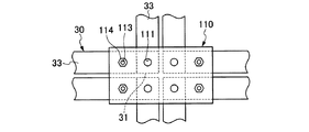
実施例6のユニット建物10に適用されるジョイント板310は、実施例4で用いたジョイント板110の変形例である。ジョイント板310は、図19に示す如く、ジョイント板110において各連結材50(鉄筋棒51)を挿通可能にした挿通孔111と同様の4個の挿通孔311を備えるとともに、これらの4個の挿通孔311と、4個の建物ユニット30(又は40)の相隣接する4個の柱31(又は41)における上エンドプレート31E(又は41E)が備えて各連結材50(鉄筋棒51)を挿通可能にした各挿通孔31H(又は41H)とが図20に示す如く、平面視で高精度に同一位置となるように設定し、かつ各連結材50(鉄筋棒51)がそれらの挿通孔311、挿通孔31H(又は41H)に径方向で隙間なく挿通するようにしたものである。
Example 6 (FIGS. 18 to 20)
A joint plate 310 applied to the unit building 10 of the sixth embodiment is a modification of the joint plate 110 used in the fourth embodiment. As shown in FIG. 19, the joint plate 310 includes four insertion holes 311 similar to the insertion holes 111 through which the connecting members 50 (rebar bars 51) can be inserted in the joint plate 110. The upper end plate 31E (or 41E) in the four columns 31 (or 41) adjacent to each other of the insertion hole 311 and the four building units 30 (or 40) is provided, and each connecting member 50 (reinforcing bar 51) is provided. As shown in FIG. 20, the insertion holes 31H (or 41H) that can be inserted are set at the same position with high accuracy in plan view, and the connecting members 50 (rebar bars 51) are inserted into the insertion holes. 311 is inserted through the insertion hole 31H (or 41H) in the radial direction without a gap.

これにより、ユニット建物10の外郭に囲まれた内部に位置して相隣接する4個の建物ユニット30(又は40)の各柱31(又は41)を、図18(A)に示す如く、連結材50(鉄筋棒51)により下部構造体たる基礎20に緊結するとともに、それらの4個の建物ユニット30(又は40)の上部の天井梁33(又は43)が図18(B)、(C)に示す如くジョイント板310を介して接合されるものになる。ジョイント板310を用い、かつ連結材50を用いることにより、水平方向にて相隣接する複数の建物ユニット30(又は40)を互いに簡易かつ確実に接合できる。連結材50が、柱31(又は41)の上端に設けたエンドプレート31E(又は41E)の挿通孔31H(又は41H)に対する嵌合精度と、ジョイント板310に設けた挿通孔311に対する嵌合精度を高精度に設定することにより、複数の建物ユニット30(又は40)の水平方向の接合位置精度を向上できる。連結材50(鉄筋棒51)は建物ユニット30(又は40)の柱31(又は41)を下部構造体に緊結する機能と、相隣接する建物ユニット30(又は40)の上部を接合する機能とを併せ果たすものであり、その軸径は大きくなる。   As a result, the columns 31 (or 41) of the four building units 30 (or 40) adjacent to each other located inside the unit building 10 are connected as shown in FIG. The material 50 (reinforcing bar 51) is fastened to the foundation 20 which is the lower structure, and the ceiling beams 33 (or 43) on the upper part of the four building units 30 (or 40) are shown in FIGS. As shown in FIG. By using the joint plate 310 and the connecting member 50, a plurality of building units 30 (or 40) adjacent to each other in the horizontal direction can be easily and reliably joined to each other. The connecting material 50 is fitted into the insertion hole 31H (or 41H) of the end plate 31E (or 41E) provided at the upper end of the column 31 (or 41), and is fitted into the insertion hole 311 provided in the joint plate 310. Is set with high accuracy, it is possible to improve the accuracy of the horizontal position of the plurality of building units 30 (or 40). The connecting member 50 (reinforcing bar 51) has a function of binding the column 31 (or 41) of the building unit 30 (or 40) to the lower structure and a function of joining the upper parts of the adjacent building units 30 (or 40). The shaft diameter is increased.

尚、実施例4で用いた他のジョイント板120、130も、各連結材50(鉄筋棒51)を挿通可能にした挿通孔111と同様の挿通孔311を上述の如くに備えることで、各連結材50(鉄筋棒51)を併せ用いて各建物ユニット30(又は40)を水平方向にて接合するジョイント板に変更できる。   In addition, the other joint plates 120 and 130 used in Example 4 are also provided with the insertion holes 311 similar to the insertion holes 111 through which the connecting members 50 (rebar bars 51) can be inserted as described above. It can change into the joint board which joins each building unit 30 (or 40) in a horizontal direction using the connection material 50 (rebar 51) together.

以上、本発明の実施例を図面により詳述したが、本発明の具体的な構成はこの実施例に限られるものではなく、本発明の要旨を逸脱しない範囲の設計の変更等があっても本発明に含まれる。例えば、本発明は3階建以上のユニット建物にも適用できる。   The embodiment of the present invention has been described in detail with reference to the drawings. However, the specific configuration of the present invention is not limited to this embodiment, and even if there is a design change or the like without departing from the gist of the present invention. It is included in the present invention. For example, the present invention can be applied to a unit building having three or more stories.

本発明は、下部構造体の上に積層された建物ユニットを、該下部構造体に連結する建物ユニットの連結構造において、建物ユニットの柱の中空部に挿通された連結材により、建物ユニットの柱と下部構造体とを緊結するようにしたものである。これにより、ユニット建物の外郭に対していかなる位置にある建物ユニットの柱であっても、当該柱を下部構造体に確実に緊結することにある。   The present invention relates to a building unit connection structure in which a building unit stacked on a lower structure is connected to the lower structure, with a connecting member inserted in a hollow portion of the column of the building unit. And the lower structure. Thereby, even if it is the pillar of the building unit in any position with respect to the outline of the unit building, the pillar is securely bonded to the lower structure.

10 ユニット建物
20 基礎
22 H形鋼
22F フランジ
22H 連結孔
30 下階建物ユニット
31 柱
33 天井梁
34 C形鋼
34F フランジ
34H 連結孔
40 上階建物ユニット
41 柱
43 天井梁
50、60、70 連結材
61、71 ワイヤ
110、120、130 ジョイント板
113、115 ボルト
210 ジョイント板
212 ピン
310 ジョイント板
311 挿通孔
10 unit building 20 foundation 22 H-shaped steel 22F flange 22H connecting hole 30 lower-floor building unit 31 pillar 33 ceiling beam 34 C-shaped steel 34F flange 34H connecting hole 40 upper-floor building unit 41 pillar 43 ceiling beams 50, 60, 70 connecting material 61, 71 Wire 110, 120, 130 Joint plate 113, 115 Bolt 210 Joint plate 212 Pin 310 Joint plate 311 Insertion hole

Claims (13)

下部構造体の上に積層された建物ユニットを、該下部構造体に連結する建物ユニットの連結構造において、
建物ユニットの柱の中空部に上下に貫通するように挿通された連結材により、建物ユニットの柱と下部構造体とを緊結することを特徴とする建物ユニットの連結構造。
In the building unit connection structure for connecting the building unit stacked on the lower structure to the lower structure,
A building unit connection structure characterized in that a column of the building unit and the lower structure are tightly connected by a connecting material inserted so as to penetrate vertically through the hollow portion of the column of the building unit.
前記建物ユニットの柱の中空部に挿通された連結材の下端部を下部構造体に連結するとともに、該連結材の上端部を建物ユニットにおける上記柱の上端に連結する請求項1に記載の建物ユニットの連結構造。   The building according to claim 1, wherein a lower end portion of a connecting member inserted into a hollow portion of the pillar of the building unit is connected to a lower structure, and an upper end portion of the connecting member is connected to an upper end of the column in the building unit. Unit connection structure. 前記下部構造体がフランジとウエブを備えた形鋼を有してなり、連結材の下端部が該下部構造体における形鋼のフランジに設けた連結孔に挿通されて該フランジの下面に係止されてなる請求項2に記載の建物ユニットの連結構造。   The lower structure has a shape steel provided with a flange and a web, and the lower end portion of the connecting material is inserted into a connection hole provided in the flange of the shape steel in the lower structure and locked to the lower surface of the flange. The connection structure of the building unit of Claim 2 formed. 前記下部構造体がH形鋼を横置きした基礎からなり、連結材の下端部が該基礎におけるH形鋼のフランジに設けた連結孔に挿通されて該フランジの下面に係止されてなる請求項3に記載の建物ユニットの連結構造。   The lower structure is composed of a foundation on which H-shaped steel is horizontally placed, and a lower end portion of a coupling material is inserted into a coupling hole provided in a flange of the H-shaped steel in the foundation and locked to the lower surface of the flange. Item 5. A connecting structure of building units according to item 3. 前記下部構造体がC形鋼からなる梁を有する下階建物ユニットからなり、連結材の下端部が該下階建物ユニットの梁におけるC形鋼のフランジに設けた連結孔に挿通されて該フランジの下面に係止されてなる請求項3に記載の建物ユニットの連結構造。   The lower structure is composed of a lower floor building unit having a beam made of C-shaped steel, and the lower end portion of the connecting material is inserted into a connecting hole provided in a flange of the C-shaped steel in the beam of the lower floor building unit. The connecting structure for building units according to claim 3, wherein the structure is locked to the lower surface of the building unit. 前記連結材がワイヤからなる請求項1〜5のいずれかに記載の建物ユニットの連結構造。   The building unit connection structure according to claim 1, wherein the connection member is made of a wire. 前記下部構造体の上に、水平方向に相隣接する複数の建物ユニットを積層し、それらの相隣接する建物ユニットの各上部がジョイント板を介して互いに接合される請求項1〜6のいずれかに記載の建物ユニットの連結構造。   A plurality of building units adjacent to each other in the horizontal direction are stacked on the lower structure, and upper portions of the adjacent building units are joined to each other via a joint plate. Connecting structure of building units described in 1. 前記相隣接する建物ユニットの各上部が、ボルトによりジョイント板に締結されてなる請求項7に記載の建物ユニットの連結構造。   The connecting structure for building units according to claim 7, wherein upper portions of the adjacent building units are fastened to a joint plate by bolts. 前記相隣接する建物ユニットの各上部が備える孔に、ジョイント板に設けたピンを係合してなる請求項7に記載の建物ユニットの連結方法。   The method of connecting building units according to claim 7, wherein a pin provided on a joint plate is engaged with a hole provided in each upper part of the adjacent building units. 前記相隣接する建物ユニットの各柱の上端に設けたエンドプレートが備える挿通孔のそれぞれに隙間なく挿通された前記連結材のそれぞれが、ジョイント板に設けた孔に係入されてなる請求項7に記載の建物ユニットの連結方法。   Each of the said connection material penetrated by each of the insertion hole with which the end plate provided in the upper end of each pillar of the said adjacent building unit is provided without a clearance gap is inserted in the hole provided in the joint board. Method for connecting building units as described in 1. 下部構造体の上に積層された建物ユニットを、該下部構造体に連結する建物ユニットの連結方法において、
建物ユニットの柱の中空部に連結材を挿通し、この連結材により建物ユニットの柱と下部構造体とを緊結することを特徴とする建物ユニットの連結方法。
In the building unit connection method for connecting a building unit stacked on the lower structure to the lower structure,
A connecting method for a building unit, wherein a connecting material is inserted into a hollow part of the column of the building unit, and the column of the building unit and the lower structure are tightly connected by the connecting material.
前記建物ユニットの柱の中空部に挿通された連結材の下端部を下部構造体に連結するとともに、該連結材の上端部を建物ユニットにおける上記柱の上端に連結する請求項11に記載の建物ユニットの連結方法。   The building according to claim 11, wherein a lower end portion of a connecting member inserted into a hollow portion of a column of the building unit is connected to a lower structure, and an upper end portion of the connecting member is connected to an upper end of the column in the building unit. Unit connection method. 前記下部構造体の上に複数の相隣接する建物ユニットを積層し、それらの相隣接する建物ユニットの各上部がジョイント板を介して互いに接合される請求項11又は12に記載の建物ユニットの連結方法。   The connection of building units according to claim 11 or 12, wherein a plurality of adjacent building units are stacked on the lower structure, and upper portions of the adjacent building units are joined to each other via a joint plate. Method.
JP2013118312A 2013-03-14 2013-06-04 Building unit connection structure Expired - Fee Related JP6235245B2 (en)

Priority Applications (1)

Application Number Priority Date Filing Date Title
JP2013118312A JP6235245B2 (en) 2013-03-14 2013-06-04 Building unit connection structure

Applications Claiming Priority (3)

Application Number Priority Date Filing Date Title
JP2013052485 2013-03-14
JP2013118312A JP6235245B2 (en) 2013-03-14 2013-06-04 Building unit connection structure

Publications (2)

Publication Number Publication Date
JP2014198985A true JP2014198985A (en) 2014-10-23
JP6235245B2 JP6235245B2 (en) 2017-11-22

Family

ID=52356047

Family Applications (1)

Application Number Title Priority Date Filing Date
JP2013118312A Expired - Fee Related JP6235245B2 (en) 2013-03-14 2013-06-04 Building unit connection structure

Country Status (1)

Country Link
JP (1) JP6235245B2 (en)

Cited By (4)

* Cited by examiner, † Cited by third party
Publication number Priority date Publication date Assignee Title
JP6029711B1 (en) * 2015-05-28 2016-11-24 株式会社渋谷 Unit building
KR102112600B1 (en) 2018-12-13 2020-05-19 주식회사 포스코에이앤씨건축사사무소 Connecting structure of modular construction without internal/external decoration's damage and modular construction using thereof and the making method for modular construction
KR20210126874A (en) * 2020-04-13 2021-10-21 주식회사 포스코 Composite column
JP2022016579A (en) * 2016-12-02 2022-01-21 エムアールシービー イノベーションズ スンディリアン ブルハド Connection system and method for prefabrication type volumetric building module

Citations (5)

* Cited by examiner, † Cited by third party
Publication number Priority date Publication date Assignee Title
US4023315A (en) * 1968-07-26 1977-05-17 Elcon A.G. Prefabricated buildings
JPH0514308U (en) * 1991-08-07 1993-02-23 大和ハウス工業株式会社 Unit box
JPH11256696A (en) * 1998-03-11 1999-09-21 Misawa Homes Co Ltd Connecting plate and connecting method of building unit
JP2001152555A (en) * 1999-11-30 2001-06-05 Sekisui Chem Co Ltd Connecting method and joint plate for building unit
JP2012070281A (en) * 2010-09-24 2012-04-05 Canon Inc Imaging system, information processor, and information processing method

Patent Citations (5)

* Cited by examiner, † Cited by third party
Publication number Priority date Publication date Assignee Title
US4023315A (en) * 1968-07-26 1977-05-17 Elcon A.G. Prefabricated buildings
JPH0514308U (en) * 1991-08-07 1993-02-23 大和ハウス工業株式会社 Unit box
JPH11256696A (en) * 1998-03-11 1999-09-21 Misawa Homes Co Ltd Connecting plate and connecting method of building unit
JP2001152555A (en) * 1999-11-30 2001-06-05 Sekisui Chem Co Ltd Connecting method and joint plate for building unit
JP2012070281A (en) * 2010-09-24 2012-04-05 Canon Inc Imaging system, information processor, and information processing method

Cited By (8)

* Cited by examiner, † Cited by third party
Publication number Priority date Publication date Assignee Title
JP6029711B1 (en) * 2015-05-28 2016-11-24 株式会社渋谷 Unit building
JP2016223111A (en) * 2015-05-28 2016-12-28 株式会社渋谷 Unit Building
JP2022016579A (en) * 2016-12-02 2022-01-21 エムアールシービー イノベーションズ スンディリアン ブルハド Connection system and method for prefabrication type volumetric building module
JP7288031B2 (en) 2016-12-02 2023-06-06 エムアールシービー イノベーションズ スンディリアン ブルハド Connection system and method for prefabricated volumetric building modules
KR102112600B1 (en) 2018-12-13 2020-05-19 주식회사 포스코에이앤씨건축사사무소 Connecting structure of modular construction without internal/external decoration's damage and modular construction using thereof and the making method for modular construction
WO2020122307A1 (en) * 2018-12-13 2020-06-18 주식회사 포스코에이앤씨건축사사무소 Building module joint structure enabling coupling without damaging interior/exterior material, modular building using same and method for manufacturing modular building
KR20210126874A (en) * 2020-04-13 2021-10-21 주식회사 포스코 Composite column
KR102382353B1 (en) * 2020-04-13 2022-04-04 주식회사 포스코 Composite column

Also Published As

Publication number Publication date
JP6235245B2 (en) 2017-11-22

Similar Documents

Publication Publication Date Title
JP5707418B2 (en) Concatenation method for container-type unit construction
KR102079008B1 (en) E-z connecting structure for beam and column wherein the end-moment and bending resistibility are reinforced
JP6235245B2 (en) Building unit connection structure
WO2015140890A1 (en) Column structure and base member
KR20130139029A (en) Modular column joint structure using h shape steel plate
KR20100023089A (en) H-beam connecting structure
KR101625136B1 (en) the self positioning joint structure between precast steel-concrete composite column and precast steel-concrete composite beam
KR101129502B1 (en) Synthetic girder of i type
JP2016216955A (en) External facing material installing structure
JP2009102909A (en) Embedded hardware and method of mounting the same
JP2009249900A (en) Precast concrete beam member, and laminated beam
KR20160035541A (en) the self positioning joint structure between precast steel-concrete composite column and precast steel-concrete composite beam
KR100963586B1 (en) Attachment of Unit Modular System, Modular Unit And Manufacturing Method of The Modular Unit
JP6336773B2 (en) Joining structure and erection method of mountain retaining H-shaped steel pile
JP2006348490A (en) Brace mounting structure
JP6435576B2 (en) Construction method for substructure including crossbar
JP6353647B2 (en) Seismic isolation device joint structure
JP5344702B2 (en) Column and slab joint structure
JP2012241467A (en) Wall and floor type reinforced concrete structure
JP6893789B2 (en) Beam flint connection structure and beam flint connection piece
JP5439002B2 (en) Expansion unit mounting structure, expansion unit mounting method and unit type building
JP4814019B2 (en) Joint structure and method of pile and superstructure
JP5891982B2 (en) Bearing wall joint structure
JP2005240422A (en) Beam-column joint
JP2018009355A (en) Column-beam joint structure

Legal Events

Date Code Title Description
A621 Written request for application examination

Free format text: JAPANESE INTERMEDIATE CODE: A621

Effective date: 20160105

A131 Notification of reasons for refusal

Free format text: JAPANESE INTERMEDIATE CODE: A131

Effective date: 20161025

A977 Report on retrieval

Free format text: JAPANESE INTERMEDIATE CODE: A971007

Effective date: 20161026

A521 Written amendment

Free format text: JAPANESE INTERMEDIATE CODE: A523

Effective date: 20161128

A131 Notification of reasons for refusal

Free format text: JAPANESE INTERMEDIATE CODE: A131

Effective date: 20170509

A521 Written amendment

Free format text: JAPANESE INTERMEDIATE CODE: A523

Effective date: 20170522

TRDD Decision of grant or rejection written
A01 Written decision to grant a patent or to grant a registration (utility model)

Free format text: JAPANESE INTERMEDIATE CODE: A01

Effective date: 20171003

A61 First payment of annual fees (during grant procedure)

Free format text: JAPANESE INTERMEDIATE CODE: A61

Effective date: 20171026

R151 Written notification of patent or utility model registration

Ref document number: 6235245

Country of ref document: JP

Free format text: JAPANESE INTERMEDIATE CODE: R151

LAPS Cancellation because of no payment of annual fees