JP2014197527A - Vehicle direction indicator - Google Patents
Vehicle direction indicator Download PDFInfo
- Publication number
- JP2014197527A JP2014197527A JP2013200007A JP2013200007A JP2014197527A JP 2014197527 A JP2014197527 A JP 2014197527A JP 2013200007 A JP2013200007 A JP 2013200007A JP 2013200007 A JP2013200007 A JP 2013200007A JP 2014197527 A JP2014197527 A JP 2014197527A
- Authority
- JP
- Japan
- Prior art keywords
- light
- direction indicator
- outer cover
- vehicle
- resin
- Prior art date
- Legal status (The legal status is an assumption and is not a legal conclusion. Google has not performed a legal analysis and makes no representation as to the accuracy of the status listed.)
- Pending
Links
Images


Classifications
-
- F—MECHANICAL ENGINEERING; LIGHTING; HEATING; WEAPONS; BLASTING
- F21—LIGHTING
- F21S—NON-PORTABLE LIGHTING DEVICES; SYSTEMS THEREOF; VEHICLE LIGHTING DEVICES SPECIALLY ADAPTED FOR VEHICLE EXTERIORS
- F21S43/00—Signalling devices specially adapted for vehicle exteriors, e.g. brake lamps, direction indicator lights or reversing lights
- F21S43/10—Signalling devices specially adapted for vehicle exteriors, e.g. brake lamps, direction indicator lights or reversing lights characterised by the light source
- F21S43/13—Signalling devices specially adapted for vehicle exteriors, e.g. brake lamps, direction indicator lights or reversing lights characterised by the light source characterised by the type of light source
- F21S43/14—Light emitting diodes [LED]
-
- F—MECHANICAL ENGINEERING; LIGHTING; HEATING; WEAPONS; BLASTING
- F21—LIGHTING
- F21S—NON-PORTABLE LIGHTING DEVICES; SYSTEMS THEREOF; VEHICLE LIGHTING DEVICES SPECIALLY ADAPTED FOR VEHICLE EXTERIORS
- F21S43/00—Signalling devices specially adapted for vehicle exteriors, e.g. brake lamps, direction indicator lights or reversing lights
- F21S43/20—Signalling devices specially adapted for vehicle exteriors, e.g. brake lamps, direction indicator lights or reversing lights characterised by refractors, transparent cover plates, light guides or filters
- F21S43/255—Filters
-
- F—MECHANICAL ENGINEERING; LIGHTING; HEATING; WEAPONS; BLASTING
- F21—LIGHTING
- F21S—NON-PORTABLE LIGHTING DEVICES; SYSTEMS THEREOF; VEHICLE LIGHTING DEVICES SPECIALLY ADAPTED FOR VEHICLE EXTERIORS
- F21S43/00—Signalling devices specially adapted for vehicle exteriors, e.g. brake lamps, direction indicator lights or reversing lights
- F21S43/20—Signalling devices specially adapted for vehicle exteriors, e.g. brake lamps, direction indicator lights or reversing lights characterised by refractors, transparent cover plates, light guides or filters
- F21S43/26—Refractors, transparent cover plates, light guides or filters not provided in groups F21S43/235 - F21S43/255
-
- F—MECHANICAL ENGINEERING; LIGHTING; HEATING; WEAPONS; BLASTING
- F21—LIGHTING
- F21V—FUNCTIONAL FEATURES OR DETAILS OF LIGHTING DEVICES OR SYSTEMS THEREOF; STRUCTURAL COMBINATIONS OF LIGHTING DEVICES WITH OTHER ARTICLES, NOT OTHERWISE PROVIDED FOR
- F21V13/00—Producing particular characteristics or distribution of the light emitted by means of a combination of elements specified in two or more of main groups F21V1/00 - F21V11/00
- F21V13/12—Combinations of only three kinds of elements
- F21V13/14—Combinations of only three kinds of elements the elements being filters or photoluminescent elements, reflectors and refractors
-
- F—MECHANICAL ENGINEERING; LIGHTING; HEATING; WEAPONS; BLASTING
- F21—LIGHTING
- F21V—FUNCTIONAL FEATURES OR DETAILS OF LIGHTING DEVICES OR SYSTEMS THEREOF; STRUCTURAL COMBINATIONS OF LIGHTING DEVICES WITH OTHER ARTICLES, NOT OTHERWISE PROVIDED FOR
- F21V3/00—Globes; Bowls; Cover glasses
- F21V3/04—Globes; Bowls; Cover glasses characterised by materials, surface treatments or coatings
- F21V3/06—Globes; Bowls; Cover glasses characterised by materials, surface treatments or coatings characterised by the material
- F21V3/08—Globes; Bowls; Cover glasses characterised by materials, surface treatments or coatings characterised by the material the material comprising photoluminescent substances
-
- F—MECHANICAL ENGINEERING; LIGHTING; HEATING; WEAPONS; BLASTING
- F21—LIGHTING
- F21V—FUNCTIONAL FEATURES OR DETAILS OF LIGHTING DEVICES OR SYSTEMS THEREOF; STRUCTURAL COMBINATIONS OF LIGHTING DEVICES WITH OTHER ARTICLES, NOT OTHERWISE PROVIDED FOR
- F21V9/00—Elements for modifying spectral properties, polarisation or intensity of the light emitted, e.g. filters
- F21V9/30—Elements containing photoluminescent material distinct from or spaced from the light source
-
- F—MECHANICAL ENGINEERING; LIGHTING; HEATING; WEAPONS; BLASTING
- F21—LIGHTING
- F21W—INDEXING SCHEME ASSOCIATED WITH SUBCLASSES F21K, F21L, F21S and F21V, RELATING TO USES OR APPLICATIONS OF LIGHTING DEVICES OR SYSTEMS
- F21W2103/00—Exterior vehicle lighting devices for signalling purposes
- F21W2103/20—Direction indicator lights
- F21W2103/25—Direction indicator lights for rear-view mirrors
-
- F—MECHANICAL ENGINEERING; LIGHTING; HEATING; WEAPONS; BLASTING
- F21—LIGHTING
- F21Y—INDEXING SCHEME ASSOCIATED WITH SUBCLASSES F21K, F21L, F21S and F21V, RELATING TO THE FORM OR THE KIND OF THE LIGHT SOURCES OR OF THE COLOUR OF THE LIGHT EMITTED
- F21Y2115/00—Light-generating elements of semiconductor light sources
- F21Y2115/10—Light-emitting diodes [LED]
Abstract
Description
本発明は、車両用方向指示器、特に、車両の外部(前方、側方及び後方)に、車両の進行方向の変更を知らせるため、車両の外面(前面、側面及び後面)の上に又は該外面部に一体化して設けられる車両用方向指示器に関する。 The present invention provides a directional indicator for a vehicle, in particular, on the outer surface (front surface, side surface and rear surface) of the vehicle in order to inform the outside of the vehicle (front, side and rear) of the change of the traveling direction of the vehicle. The present invention relates to a vehicular direction indicator provided integrally with an outer surface portion.
車両にはその進行方向を変更する際に、進行方向を周囲に知らせるための方向指示器が取り付けられている。こうした方向指示器には、通常、白熱電球、ハロゲン電球を用い、橙色に着色した透光性樹脂によって橙色を点灯するもの、クリアカバーレンズの使用を可能とする、白熱電球、ハロゲン電球のバルブ表面に橙色塗装して橙色を点灯するもの、低消費電力、小型化の利点を利用して、バルブ電球の代わりに橙色LEDを光源として橙色を点灯するものなどが用いられている。特に、点光源を使用したこれらの方向指示器の場合は、通常、方向指示器の保安基準を満たすために、アウターレンズに凹凸形状を形成することにより、光を散乱させ、発光面積を広げる構造を採用している。 The vehicle is provided with a direction indicator for informing the surroundings of the traveling direction when the traveling direction is changed. For these direction indicators, incandescent bulbs and halogen bulbs are usually used, which are lit in orange with translucent resin colored orange, and the surface of the bulbs of incandescent bulbs and halogen bulbs that can use clear cover lenses. In other words, the one that lights orange by painting orange, and the one that lights orange by using an orange LED as a light source instead of a bulb light bulb are used in order to take advantage of low power consumption and downsizing. In particular, in the case of these direction indicators using a point light source, in general, in order to satisfy the safety standard of the direction indicator, a structure that scatters light and widens the emission area by forming an uneven shape on the outer lens. Is adopted.
更に、車両用方向指示器のなかには、車両のドアに設けられるドアミラーに方向指示器を取り付けて、車両の前後に設けられる方向指示器と共に点灯させることにより、周囲に対して、進行方向の変更をより確実に知らせることができるようにしたものが実用化されている。 Furthermore, in some vehicle direction indicators, a direction indicator is attached to a door mirror provided on the door of the vehicle and is turned on together with direction indicators provided on the front and rear of the vehicle, thereby changing the direction of travel relative to the surroundings. The one that can be surely notified is put into practical use.
しかし、このような従来の白熱電球、ハロゲン電球、橙色LEDを使用した車両用方向指示器は、点光源であるため、アウターレンズに光散乱加工をしたとしても、アウターレンズの中心部の輝度は高いが、アウターレンズの外周縁部の輝度が低いという問題があった。また、方向指示器に対する角度によっては、視認性が非常に悪く、点滅状態が視認しづらいという問題があった。 However, since the conventional vehicle direction indicator using such incandescent bulb, halogen bulb, and orange LED is a point light source, even if the outer lens is subjected to light scattering processing, the luminance at the center of the outer lens is Although it is high, there was a problem that the brightness of the outer peripheral edge of the outer lens was low. Further, depending on the angle with respect to the direction indicator, there is a problem that the visibility is very poor and the blinking state is difficult to visually recognize.
特に、点光源から光を全面に広げるために、アウターレンズに光散乱加工をしている場合、アウターレンズからの光が、視認方向によっては、人に眩しさを与えるグレアを生じ、運転者、歩行者に不快感を与える。このようなグレアは、状況判断能力の急激な低下を招き、危険である。更に、橙色LEDを用いてライン状に光を点灯させる方向指示器の場合、ラインに沿って相応の面積を発光させるため、多数の橙色LEDを配置して発光面積を得る必要があり、コスト上、不利であった。 In particular, when the outer lens is subjected to light scattering processing in order to spread light from the point light source over the entire surface, the light from the outer lens may cause glare that gives glare to the person depending on the viewing direction, Discomfort to pedestrians. Such glare is dangerous because it causes a sudden decline in the ability to judge situations. Furthermore, in the case of a direction indicator that uses orange LEDs to illuminate light in a line shape, it is necessary to obtain a light emitting area by arranging a large number of orange LEDs in order to emit a corresponding area along the line. It was disadvantageous.
本発明は、上記事情に鑑みてなされたものであり、照射光軸方向はもとより、照射光軸から外れた角度からも、必要十分な光度と良好な視認性を与え、また、グレアの発生が抑制された車両用方向指示器を提供することを目的とする。 The present invention has been made in view of the above circumstances, and provides the necessary and sufficient luminous intensity and good visibility from the angle deviated from the irradiation optical axis as well as the irradiation optical axis direction, and the occurrence of glare. An object is to provide a vehicular direction indicator that is suppressed.
本発明者らは、上記課題を解決するために鋭意検討を重ねた結果、光源として青色光を発光する青色LEDと、青色光が照射されるアウターカバーとを備え、更に、青色LEDが配設されたベースハウジングを任意に備え、アウターカバーとして、青色光を吸収して発光する蛍光体を分散させて成形した高分子材料からなる成形体を用い、青色LEDから発光した青色光が、アウターカバーに照射されるように構成することにより、成形体中の蛍光体が、青色光により励起されて、波長変換された光を発光してアウターカバー全体が発光し、これにより光を等方的に照射する車両用方向指示器となること、換言すれば、配光分布特性が非常に広角である車両用方向指示器となることを見出した。そして、このような車両用方向指示器が、照射光軸方向はもとより、照射光軸から外れた角度からも、必要十分な光度と良好な視認性を与え、また、グレアの発生が抑制された車両用方向指示器となることを見出し、本発明をなすに至った。 As a result of intensive studies in order to solve the above problems, the present inventors have, as a light source, a blue LED that emits blue light, an outer cover that is irradiated with blue light, and further, a blue LED is disposed. An outer cover is optionally provided, and a molded body made of a polymer material formed by dispersing a phosphor that absorbs blue light and emits light is used as an outer cover. The phosphor in the molded body is excited by the blue light, emits the wavelength-converted light, and the entire outer cover emits light, thereby making the light isotropic. It has been found that it becomes a vehicle direction indicator for irradiation, in other words, a vehicle direction indicator having a very wide light distribution characteristic. Such a vehicular direction indicator gives necessary and sufficient luminous intensity and good visibility from an angle deviating from the irradiation optical axis as well as the irradiation optical axis direction, and the occurrence of glare is suppressed. As a result, the present invention has been found.
従って、本発明は、下記の車両用方向指示器を提供する。
請求項1:
光源として青色光を発光する青色LEDと、青色光が照射されるアウターカバーとを備え、該アウターカバーが、青色光を吸収して発光する蛍光体を分散させた高分子材料からなる成形体を含むことを特徴とする車両用方向指示器。
請求項2:
更に、上記青色LEDが配設されたベースハウジングを備えることを特徴とする請求項1記載の車両用方向指示器。
請求項3:
上記蛍光体が、橙色発光蛍光体であることを特徴とする請求項1又は2記載の車両用方向指示器。
請求項4:
上記橙色発光蛍光体が、ガーネット構造を有する橙色発光蛍光体であることを特徴とする請求項3記載の車両用方向指示器。
請求項5:
上記高分子材料が、熱可塑性樹脂及び熱硬化性樹脂から選ばれる1種類以上の樹脂であることを特徴とする請求項1乃至4のいずれか1項記載の車両用方向指示器。
請求項6:
上記熱可塑性樹脂が、ポリエチレン、ポリプロピレン、ポリスチレン、ポリカーボネート、ABS樹脂及びアクリル樹脂から選ばれる1種類以上の熱可塑性樹脂であることを特徴とする請求項5記載の車両用方向指示器。
請求項7:
上記熱硬化性樹脂が、シリコーン樹脂、エポキシ樹脂、フェノール樹脂、ウレタン樹脂及び不飽和ポリエステル樹脂から選ばれる1種類以上の熱硬化性樹脂であることを特徴とする請求項5又は6記載の車両用方向指示器。
請求項8:
上記青色LEDが、発光部をなす素子を、光散乱剤を分散した封止材で封止してなる青色LEDであることを特徴とする請求項1乃至7のいずれか1項記載の車両用方向指示器。
請求項9:
上記青色LEDの発光方向前方に、光散乱剤を分散した散光部材を備えることを特徴とする請求項1乃至7のいずれか1項記載の車両用方向指示器。
請求項10:
上記青色LEDの発光方向前方に、青色LEDから発光した青色光に配光角を与えるレンズを備えることを特徴とする請求項1乃至7のいずれか1項記載の車両用方向指示器。
請求項11:
上記アウターカバーが、表面に、凹凸形状のテクスチャを有することを特徴とする請求項1乃至10のいずれか1項記載の車両用方向指示器。
請求項12:
更に、上記アウターカバーの外側にカラーフィルターを備えることを特徴とする請求項1乃至10のいずれか1項記載の車両用方向指示器。
請求項13:
上記カラーフィルターが、表面に、凹凸形状のテクスチャを有することを特徴とする請求項12記載の車両用方向指示器。
請求項14:
車両外部に光を照射するように、車両外表面部に一体化して用いられることを特徴とする請求項1乃至13のいずれか1項記載の車両用方向指示器。
Accordingly, the present invention provides the following vehicle direction indicator.
Claim 1:
A molded body made of a polymer material that includes a blue LED that emits blue light as a light source and an outer cover that is irradiated with blue light, the outer cover absorbing phosphors that absorb blue light and emit light. A vehicular direction indicator characterized by including.
Claim 2:
The vehicle direction indicator according to
Claim 3:
3. The vehicular direction indicator according to
Claim 4:
4. The vehicle direction indicator according to claim 3, wherein the orange light emitting phosphor is an orange light emitting phosphor having a garnet structure.
Claim 5:
The vehicular direction indicator according to any one of
Claim 6:
6. The vehicular direction indicator according to claim 5, wherein the thermoplastic resin is at least one thermoplastic resin selected from polyethylene, polypropylene, polystyrene, polycarbonate, ABS resin and acrylic resin.
Claim 7:
7. The vehicle according to claim 5, wherein the thermosetting resin is at least one thermosetting resin selected from a silicone resin, an epoxy resin, a phenol resin, a urethane resin, and an unsaturated polyester resin. Direction indicator.
Claim 8:
8. The vehicle according to any one of
Claim 9:
The vehicle direction indicator according to any one of
Claim 10:
The vehicular direction indicator according to any one of
Claim 11:
The vehicular direction indicator according to any one of
Claim 12:
The vehicle direction indicator according to any one of
Claim 13:
13. The vehicular direction indicator according to
Claim 14:
14. The vehicular direction indicator according to any one of
本発明によれば、視認性が改良され、広角にわたり十分な光度と、良好な視認性を与える車両用方向指示器を提供することができる。また、アウターカバー全体が発光する面発光であるので、アウターカバーに光散乱加工を施さなくても、光度の均一性が確保されており、その結果、光散乱加工に起因するグレアの発生を抑制することができ、周辺の車両の運転者や歩行者に不快感を与えることがなく、安全である。更に、複雑な光学設計が不要であるので、省スペースで車両に配置することができる。 ADVANTAGE OF THE INVENTION According to this invention, visibility can be improved and the direction indicator for vehicles which provides sufficient luminous intensity over a wide angle and favorable visibility can be provided. In addition, since the entire outer cover emits light, the light intensity is uniform even without light scattering processing on the outer cover, and as a result, the occurrence of glare due to light scattering processing is suppressed. It is safe without causing discomfort to the drivers and pedestrians of the surrounding vehicles. Furthermore, since a complicated optical design is unnecessary, it can be arranged in a vehicle in a small space.
以下、本発明について詳細に説明する。
本発明の車両用方向指示器は、光源として青色光を発光する青色LEDと、青色光が照射されるアウターカバーとを備える。車両用方向指示器は、ベースハウジングを備えていてもよい。青色LEDは、一般的には、ベースハウジングに配設されるが、サポートフレーム等を用いてアウターカバーに取り付けることもできる。
Hereinafter, the present invention will be described in detail.
The vehicular direction indicator of the present invention includes a blue LED that emits blue light as a light source, and an outer cover that is irradiated with the blue light. The vehicle direction indicator may include a base housing. The blue LED is generally disposed in the base housing, but can be attached to the outer cover using a support frame or the like.
光源となる青色LEDには、中心波長が波長420nm以上490nm以下の範囲内にある光を発するものが好適に用いられる。青色LEDのサイズ、パワー、数量については、車両用方向指示器としての光量、視認性、注意喚起の機能、デザイン性などを考慮して、必要なものを適宜選択し、発光部となる素子を1個有する青色LED又は発光部となる素子を複数個有する青色LEDを、1個で又は複数個組み合わせて用いることができ、市販品を用いてよい。また、青色LEDとしては、発光部をなす素子を、光散乱剤を分散した樹脂等の封止材で封止した青色LEDを用いることができ、青色LEDの発光方向前方に、光散乱剤を分散した樹脂等の散光部材を設けてもよい。これらにより、励起光である青色光を散乱させ、アウターカバーを更に均一発光させることができる。あるいは、青色LEDの発光方向前方に、青色LEDから発光した青色光に配光角を与えるレンズを設けてもよい。 As the blue LED serving as the light source, one that emits light having a center wavelength in the range of a wavelength of 420 nm or more and 490 nm or less is suitably used. Regarding the size, power, and quantity of the blue LED, select the necessary one in consideration of the amount of light as a vehicular direction indicator, visibility, alerting function, design, etc. A single blue LED or a blue LED having a plurality of elements to be light emitting portions can be used singly or in combination, and a commercially available product may be used. Moreover, as blue LED, the blue LED which sealed the element which makes a light emission part with sealing materials, such as resin which disperse | distributed the light-scattering agent, can be used, and a light-scattering agent is used ahead of the light emission direction of blue LED. A light diffusing member such as a dispersed resin may be provided. By these, the blue light which is excitation light can be scattered, and an outer cover can be light-emitted more uniformly. Or you may provide the lens which gives a light distribution angle to the blue light light-emitted from blue LED ahead of the light emission direction of blue LED.
本発明の車両用方向指示器では、青色光が照射される位置、特に青色LEDの発光方向前方にアウターカバーが設けられる。このアウターカバーは、青色光を吸収して発光する蛍光体を分散させた高分子材料からなる成形体を含む。本発明の車両用方向指示器では、青色LEDから発光した青色光は、アウターカバーに含まれる蛍光体に吸収されて、波長が変換されて発光する。蛍光体として、橙色発光蛍光体を用いた場合、橙色光、特に、波長が550nm以上610nm以下の範囲内に発光の最大強度を有する橙色光に変換される。 In the vehicular direction indicator of the present invention, the outer cover is provided at a position where the blue light is emitted, particularly in front of the light emitting direction of the blue LED. The outer cover includes a molded body made of a polymer material in which a phosphor that absorbs blue light and emits light is dispersed. In the vehicular direction indicator of the present invention, the blue light emitted from the blue LED is absorbed by the phosphor included in the outer cover, and the wavelength is converted to emit light. When an orange light emitting phosphor is used as the phosphor, it is converted into orange light, particularly orange light having a maximum emission intensity within a wavelength range of 550 nm to 610 nm.
アウターカバーを構成する高分子材料(有機高分子材料)としては、蛍光体の分散の制御のし易さの点で、熱可塑性樹脂、熱硬化性樹脂が挙げられるが、任意形状に後加工がしやすい点から熱可塑性樹脂が好ましい。更に、熱可塑性樹脂を用いた場合、アウターカバーが、振動や衝撃による割れに強く、耐衝撃、耐振動性に優れており、また、耐候性にも優れることから、車両用の部材として、特に好適なものとなる。 Examples of the polymer material (organic polymer material) constituting the outer cover include thermoplastic resins and thermosetting resins in terms of ease of controlling the dispersion of the phosphor, but post-processing can be performed in any shape. A thermoplastic resin is preferable because it is easy to do. Furthermore, when a thermoplastic resin is used, the outer cover is resistant to cracking due to vibration and impact, has excellent impact resistance and vibration resistance, and also has excellent weather resistance. This is preferable.
熱可塑性樹脂としては、ポリエチレン、ポリプロピレン、ポリスチレン、ポリカーボネート、ABS樹脂、アクリル樹脂などが好適に用いられる。一方、熱硬化性樹脂としては、シリコーン樹脂、エポキシ樹脂、フェノール樹脂、ウレタン樹脂、不飽和ポリエステル樹脂などが好適に用いられる。熱硬化性樹脂を用いる場合、使用する熱硬化性樹脂が強度・耐候性等の点で最外層に使用できない場合があるが、そのような場合には、例えば、熱可塑性樹脂で形成された最外層の内側に、蛍光体を分散させた熱硬化性樹脂からなる成形体を形成してもよい。これらの樹脂は、波長変換されて発光した橙色光等の光を最大限利用する点から、着色せずに、透明又は白色で用いることが好ましいが、発光色を調整するために着色樹脂を組み合わせて使用してもよい。着色樹脂は、蛍光体を分散させる樹脂として使用することができ、また、蛍光体を分散させた高分子材料の内層又は外層として組み合わせて使用することもできる。 As the thermoplastic resin, polyethylene, polypropylene, polystyrene, polycarbonate, ABS resin, acrylic resin and the like are preferably used. On the other hand, as the thermosetting resin, a silicone resin, an epoxy resin, a phenol resin, a urethane resin, an unsaturated polyester resin, or the like is preferably used. When a thermosetting resin is used, the thermosetting resin to be used may not be used for the outermost layer in terms of strength and weather resistance. In such a case, for example, the outermost layer formed of a thermoplastic resin may be used. A molded body made of a thermosetting resin in which a phosphor is dispersed may be formed inside the outer layer. These resins are preferably used in a transparent or white color without being colored from the viewpoint of maximizing the use of light such as orange light emitted after wavelength conversion, but in order to adjust the emission color, a combination of colored resins is used. May be used. The colored resin can be used as a resin for dispersing the phosphor, and can also be used in combination as an inner layer or an outer layer of a polymer material in which the phosphor is dispersed.
本発明の車両用方向指示器では、アウターカバーを構成する高分子材料に混合される発光成分(蛍光体)として、青色光、特に波長420nm以上490nm以下の青色光を吸収して波長を変換して発光する蛍光体、好ましくは橙色光、特に波長が550nm以上610nm以下の範囲内に発光の最大強度を有する橙色光を発光する橙色発光蛍光体を用いる。この橙色発光蛍光体としては、(Sr,Ca,Ba)2SiO4:Eu、Ca−α−サイアロン:Eu、CaGa2S4:Eu、(Y,Gd)3Al5O12:Ce、Y3Al5O12:Ce蛍光体などが好ましく、なかでも、発光強度、耐久性から、α−サイアロン構造を有するCa−α−サイアロン:Eu、ガーネット構造(ガーネット相)を有する(Y,Gd)3Al5O12:Ce、Y3Al5O12:Ce蛍光体が好ましいがこれらに限定されるものではない。より広角に光を取り出す場合は、蛍光体としては、より屈折率の高い蛍光体を高分子材料中に分散させることで、より広角に光を取り出すことができる。 In the vehicle direction indicator of the present invention, blue light, particularly blue light having a wavelength of 420 nm to 490 nm is absorbed and converted in wavelength as a light emitting component (phosphor) mixed with the polymer material constituting the outer cover. Phosphors that emit light, preferably orange light, particularly orange light emitting phosphors that emit orange light having a maximum emission intensity within a wavelength range of 550 nm to 610 nm. Examples of the orange light-emitting phosphor include (Sr, Ca, Ba) 2 SiO 4 : Eu, Ca-α-sialon: Eu, CaGa 2 S 4 : Eu, (Y, Gd) 3 Al 5 O 12 : Ce, Y 3 Al 5 O 12 : Ce phosphor and the like are preferable. Among them, Ca—α-sialon having an α-sialon structure: Eu, having a garnet structure (garnet phase) from the viewpoint of emission intensity and durability (Y, Gd) 3 Al 5 O 12: Ce, Y 3 Al 5 O 12: While Ce phosphor is preferred but is not limited thereto. In the case of extracting light at a wider angle, the phosphor can be extracted at a wider angle by dispersing a phosphor having a higher refractive index in the polymer material.
本発明の蛍光体は、公知の方法で製造することができ、また、市販品を用いることもできる。蛍光体の粒径としては、粒度分布における体積累計50%の粒径D50が好ましくは1μm以上であり、より好ましくは8μm以上である。加えて、体積累計90%の粒径D90が好ましくは30μm以下であり、より好ましくは25μm以下である。D50値が上記範囲未満の場合、青色LEDからの励起光に対して吸収・変換よりも散乱する割合が大きくなり過ぎる場合がある。なお、D50値の最大値については明確な制限はないが、D90値との関係から20μm以下が好ましい。また、D90値が上記範囲を超えると、高分子材料と混合する際などに、分散不良等の不都合が生じるおそれがある。 The phosphor of the present invention can be produced by a known method, and a commercially available product can also be used. As the particle size of the phosphor, the particle size D50 of 50% cumulative volume in the particle size distribution is preferably 1 μm or more, more preferably 8 μm or more. In addition, the particle diameter D90 with a volume cumulative 90% is preferably 30 μm or less, and more preferably 25 μm or less. When the D50 value is less than the above range, the ratio of scattering to the excitation light from the blue LED rather than absorption / conversion may be too large. In addition, although there is no clear restriction | limiting about the maximum value of D50 value, 20 micrometers or less are preferable from the relationship with D90 value. On the other hand, when the D90 value exceeds the above range, there is a possibility that inconvenience such as poor dispersion may occur when mixing with a polymer material.
なお、本発明における粒径の測定方法は、例えば気流中又は水流中に粉末原料を分散し、レーザー回折散乱法により測定して得られる値を参照することが、粒度分布の評価までできるため好ましい。 The particle diameter measurement method in the present invention is preferably because, for example, the particle size distribution can be evaluated by dispersing the powder raw material in an air stream or water stream and referring to a value obtained by measurement by a laser diffraction scattering method. .
本発明のアウターカバーには、高分子材料に発光物質である蛍光体を混合して成形した成形体が用いられる。成形は、圧縮成形、押出成形、射出成形等の公知の成形方法が適用でき、フィルム状、薄板状等の任意の形状で、適当な大きさに、車両用方向指示器の使用目的、形状や、橙色光等の光の照射態様に合わせて成形したものを用いることができ、アウターカバーを車両外表面部の形状に対応する形状に成形することも好ましい。本発明のアウターカバーの厚みは、保安基準を満足する厚みにすればよい。また、必要に応じて、アウターカバーの表面部にテクスチャ加工を施して、アウターカバーの表面に、凹凸形状のテクスチャを形成することができる。これにより、より広角に均一な光を配光することができる。 For the outer cover of the present invention, a molded body obtained by mixing a polymer material with a phosphor as a luminescent substance is used. For molding, a known molding method such as compression molding, extrusion molding, injection molding or the like can be applied. In any shape such as a film shape or a thin plate shape, the usage purpose, shape, In addition, it is possible to use one molded in accordance with the irradiation mode of light such as orange light, and it is also preferable to mold the outer cover into a shape corresponding to the shape of the outer surface portion of the vehicle. The thickness of the outer cover of the present invention may be a thickness that satisfies the safety standard. In addition, if necessary, the surface portion of the outer cover can be textured to form an uneven texture on the surface of the outer cover. Thereby, uniform light can be distributed at a wider angle.
高分子材料と蛍光体との混合比率は、アウターカバーの形状、大きさ、厚み、青色LEDとアウターカバーとの配置などに応じて異なるが、高分子材料に対する蛍光体の割合が、1質量%以上30質量%以下が好ましく、より好ましくは1質量%以上20質量%以下である。上記範囲未満の場合は、アウターカバーの大きさにもよるが、青色LEDから発光する青色光の吸収率が低く、発光が不足する場合がある。一方、上記範囲を超える場合は、蛍光体の混合割合が高すぎて、アウターカバーとしての強度が不足する場合がある。 The mixing ratio of the polymer material and the phosphor varies depending on the shape, size and thickness of the outer cover, the arrangement of the blue LED and the outer cover, and the ratio of the phosphor to the polymer material is 1% by mass. The content is preferably 30% by mass or less and more preferably 1% by mass or more and 20% by mass or less. When it is less than the above range, although it depends on the size of the outer cover, the absorption rate of blue light emitted from the blue LED is low, and light emission may be insufficient. On the other hand, when the above range is exceeded, the mixing ratio of the phosphors is too high, and the strength as the outer cover may be insufficient.
アウターカバーには発光成分である蛍光体以外に、アウターカバー全体を、より均一に発光させるために、橙色光を吸収しないシリカ、アルミナ、チタニアなどの無機化合物の粉末を分散添加してもよい。また、本発明のアウターカバーは、耐候性を高める目的で、使用する高分子材料よりも耐候性の高い別の透明材料で部材表面を被覆してもよい。 In addition to the phosphor as a light emitting component, an inorganic compound powder such as silica, alumina, and titania that does not absorb orange light may be dispersed and added to the outer cover in order to make the entire outer cover emit light more uniformly. Moreover, the outer cover of this invention may coat | cover a member surface with another transparent material whose weather resistance is higher than the polymeric material to use for the purpose of improving a weather resistance.
本発明の車両用方向指示器においては、アウターカバーの外側にカラーフィルターを設けてもよい。特に、波長変換された光の発光面の色純度を向上させる目的で、照射光の色以外の光、特に青色光を反射又は吸収する透光性カバーで、アウターカバーの外側を覆ってもよい。これは、励起光である青色光の一部がアウターカバーに吸収されずに漏れ出して、色調が変わることを防止するためである。また、必要に応じて、カラーフィルターの表面部にテクスチャ加工を施して、カラーフィルターの表面に、凹凸形状のテクスチャを形成することができる。これにより、より広角に均一な光を配光することができる。 In the vehicle direction indicator of the present invention, a color filter may be provided outside the outer cover. In particular, for the purpose of improving the color purity of the light-emitting surface of the wavelength-converted light, the outer cover may be covered with a translucent cover that reflects or absorbs light other than the color of the irradiated light, particularly blue light. . This is for preventing a part of blue light, which is excitation light, from leaking without being absorbed by the outer cover and changing the color tone. Further, if necessary, texture processing can be performed on the surface portion of the color filter to form an uneven texture on the surface of the color filter. Thereby, uniform light can be distributed at a wider angle.
本発明の車両用方向指示器は車両外部に光を照射するように、車両外表面部に一体化して用いることができる。特に、本発明の車両用方向指示器は、複雑な光学設計が不要であるので、省スペースで車両に配置することができ、車両外表面部との一体化に有利である。 The vehicular direction indicator of the present invention can be used integrally with the outer surface of the vehicle so as to emit light to the outside of the vehicle. In particular, the vehicular direction indicator of the present invention does not require a complicated optical design, and therefore can be arranged in a vehicle in a small space, which is advantageous for integration with a vehicle outer surface portion.
次に、本発明の車両用方向指示器の具体的な構造の例を、図を示して説明する。
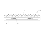
図1は、本発明の車両用方向指示器の一例(第1の態様)を示す断面図である。この車両用方向指示器1は、上面が開口した直方体形状のベースハウジング11と、車両用方向指示器1の後方側(波長変換された光の照射方向と反対方向)のベースハウジング11の内面上に設けられ、車両用方向指示器の前方側(波長変換された光の照射方向)に青色光を発光する2つの表面実装型青色LEDパッケージ12(なお、青色LEDの数は、限定されるものではない。以下の態様において同じ。)と、青色LEDパッケージ12に対して、その青色光の発光方向に対向して、車両用方向指示器1の前方側に設けられた平板状のアウターカバー13とを備える。
Next, an example of a specific structure of the vehicular direction indicator of the present invention will be described with reference to the drawings.
FIG. 1 is a cross-sectional view showing an example (first aspect) of a vehicular direction indicator of the present invention. The
青色LEDパッケージ12から発光した青色光は、直接又は車両用方向指示器の内面(ベースハウジング11の内面)などで反射されてアウターカバー13に入射する。アウターカバー13に入射した青色光は、アウターカバー13に含まれる蛍光体に吸収され、橙色光等の光に変換される。アウターカバー13から発光した橙色光等の波長変換された光は、直接又は車両用方向指示器の内面などで反射されて、車両用方向指示器1の前方に照射される。
The blue light emitted from the
図2は、本発明の車両用方向指示器の一例(第2の態様)を示す断面図である。この車両用方向指示器1は、図1の第1の態様の車両用方向指示器の平板状のアウターカバー13を、断面円弧状の凸形状のアウターカバー13としたものである。アウターカバー以外の構成は、図1と同じ参照符号を付して、説明を省略する。このような断面円弧状の凸形状のアウターカバーを用いることにより、車両用方向指示器の照射光軸に対して90°方向、更には90°を超える方向でも、十分な視認性を得ることができる。
FIG. 2 is a cross-sectional view showing an example (second aspect) of the vehicle direction indicator of the present invention. In this
図3は、本発明の車両用方向指示器の一例(第3の態様)を示す断面図である。この車両用方向指示器1は、図1の第1の態様の車両用方向指示器の青色LEDパッケージ12の青色光の発光方向前方に、光散乱剤を分散した封止材(散光部材)14を設けたものである。封止材(散光部材)14以外の構成は、図1と同じ参照符号を付して、説明を省略する。このような封止材(散光部材)を用いることにより、より均一な橙色光等の波長変換された光を照射することができる。
FIG. 3 is a cross-sectional view showing an example (third aspect) of the vehicular direction indicator of the present invention. The
図4は、本発明の車両用方向指示器の一例(第4の態様)を示す断面図である。この車両用方向指示器1は、図1の第1の態様の車両用方向指示器の平板状のアウターカバー13を、外側に凹凸形状のテクスチャを形成したアウターカバー13としたものである。アウターカバー以外の構成は、図1と同じ参照符号を付して、説明を省略する。本発明の車両用方向指示器は、面発光であり、平板状でも均一で配光角の大きい発光が得られるが、アウターカバーの表面に凹凸形状のテクスチャを形成することにより、その効果を更に高めることができる。
FIG. 4 is a cross-sectional view showing an example (fourth aspect) of the vehicle direction indicator of the present invention. This
図5は、本発明の車両用方向指示器の一例(第5の態様)を示す断面図である。この車両用方向指示器1は、図2の第2の態様の車両用方向指示器1のアウターカバー13を2層とし、内層131として、蛍光体を分散させたシリコーン樹脂を形成したものである。この内層は、蛍光体を分散させた液状シリコーン樹脂組成物を外層の内側に塗布して硬化させる、蛍光体を分散させたシリコーン樹脂シートを外層の内側に張り付けるなどの方法により形成することができる。アウターカバー以外の構成は、図2と同じ参照符号を付して、説明を省略する。
FIG. 5 is a cross-sectional view showing an example (fifth aspect) of the vehicle direction indicator of the present invention. This
車両用方向指示器の前方側に照射される光の強さは、素子(発光部)の数、青色LEDの数、電流値などによって適宜設定することができる。 The intensity of light applied to the front side of the vehicular direction indicator can be appropriately set according to the number of elements (light emitting units), the number of blue LEDs, the current value, and the like.
また、青色LEDから発光した光を効率的に使用するために、青色LEDに対して、車両用方向指示器の後方側及び/又は側方側に、反射鏡や反射板を設けてもよい。また、これらの反射鏡や反射板は、アウターカバーから発光した光を、車両用方向指示器の光の照射方向に効率的に照射させるように設置することもできる。 Moreover, in order to use efficiently the light emitted from the blue LED, a reflecting mirror or a reflecting plate may be provided on the rear side and / or the side of the vehicle direction indicator with respect to the blue LED. Moreover, these reflecting mirrors and reflecting plates can also be installed so that the light emitted from the outer cover can be efficiently irradiated in the light irradiation direction of the vehicular direction indicator.
本発明の車両用方向指示器の構造は、青色LED及びアウターカバーを備え、車両用方向指示器から発光した光を、効率的に車両用方向指示器の前方側に照射できるものであればよく、上記態様に制限されるものではない。 The structure of the vehicular direction indicator of the present invention is not limited as long as it has a blue LED and an outer cover and can efficiently radiate light emitted from the vehicular direction indicator to the front side of the vehicular direction indicator. However, the present invention is not limited to the above embodiment.
本発明の車両用方向指示器に使用されるアウターカバーでは、青色光を吸収した蛍光体が発光するものであるので、全方向に発光し、発光に指向性はない。そのため、適切な形状に成形したアウターカバーを本発明の車両用方向指示器に使用することで、点灯時の視認性がいずれの方向でも高く、視認性が均一な車両用方向指示器を得ることができる。また、本発明のアウターカバーは青色光を高効率に波長変換して利用するため、従来よりも消費電力を低減できるという利点がある。 In the outer cover used for the vehicular direction indicator of the present invention, the phosphor that absorbs the blue light emits light, so that it emits light in all directions and has no directivity in light emission. Therefore, by using an outer cover molded in an appropriate shape for the vehicular direction indicator of the present invention, it is possible to obtain a vehicular direction indicator with high visibility in any direction and uniform visibility when lighting. Can do. Moreover, since the outer cover of the present invention uses blue light after wavelength conversion with high efficiency, there is an advantage that power consumption can be reduced as compared with the conventional one.
また、車両用方向指示器として、従来適用されてきたような、点光源を用いた設計に縛られることなく、線光源、面光源を始め、立体光源のような多彩な形状の車両用方向指示器の設計も可能になり、従来よりも、車両用方向指示器のデザインの自由度が高くなり、新規デザイン、斬新なデザインを採用することが可能となる。 Moreover, as a vehicle direction indicator, it is not restricted to the design using a point light source, which has been applied in the past. The design of the device is also possible, and the degree of freedom of design of the vehicle direction indicator is higher than before, and it becomes possible to adopt a new design or a novel design.
以下に実施例及び比較例を示して本発明を具体的に説明するが、本発明は下記の実施例に制限されるものではない。 EXAMPLES The present invention will be specifically described below with reference to examples and comparative examples, but the present invention is not limited to the following examples.
[実施例1]
図1に示される車両用方向指示器を製作した。橙色発光蛍光体として、YAG:Ce蛍光体(粒度:体積累計D50=15μm、D90=21μm)をポリカーボネート樹脂に対して20質量%含有する混合物を成形してアウターカバーとした。このアウターカバーを、460nmに発光ピークを有する青色LEDを取り付けたベースハウジングと対向して配置し、アウターカバーの発光面の鉛直方向(方向指示器の照射光軸方向)を0°として、鉛直方向の発光強度と、鉛直方向から傾斜した各角度における発光強度を測定した。結果を、鉛直方向の光度に対する相対強度として表1に示す。この車両用方向指示器は0°から70°まで広角に亘り、良好な発光強度の均一性を示した。そのため、このような方向指示器は、グレアの発生の抑制が期待できる。
[Example 1]
The direction indicator for vehicles shown in FIG. 1 was manufactured. As an orange light emitting phosphor, a mixture containing 20% by mass of a YAG: Ce phosphor (particle size: cumulative volume D50 = 15 μm, D90 = 21 μm) with respect to the polycarbonate resin was molded to obtain an outer cover. This outer cover is arranged opposite to the base housing to which a blue LED having a light emission peak at 460 nm is attached, and the vertical direction of the light emission surface of the outer cover (irradiation optical axis direction of the direction indicator) is set to 0 °. The emission intensity at each angle inclined from the vertical direction was measured. The results are shown in Table 1 as relative intensity with respect to the luminous intensity in the vertical direction. This vehicular direction indicator showed good uniformity of light emission intensity over a wide angle from 0 ° to 70 °. Therefore, such a direction indicator can be expected to suppress the occurrence of glare.
[比較例1]
市販車の方向指示器について、実施例1と同様にして、アウターレンズの発光面の鉛直方向を0°として、鉛直方向の発光強度と、鉛直方向から傾斜した各角度における発光強度を測定した。結果を、鉛直方向の光度に対する相対強度として表1に示す。この方向指示器は、光源として白熱電球を用い、アウターレンズとして、光散乱加工が施され、橙色に着色された透光性樹脂が用いられている。この車両用方向指示器は、点光源をアウターレンズの光散乱加工により視野角を広げているが、アウターレンズの発光面の鉛直方向(方向指示器の照射光軸方向)から外れた位置では、発光強度の急激な低下がみられた。この方向指示器は、発光強度が低くなる角度において、保安基準を満たす発光強度以上とする必要があるため、発光強度が高い角度では、必要以上に強い光となってしまう、そのため、このような方向指示器は、グレアの発生が懸念される。
[Comparative Example 1]
About the direction indicator of a commercial vehicle, it carried out similarly to Example 1, the vertical direction of the light emission surface of the outer lens was set to 0 degree, and the light emission intensity in the vertical direction and the light emission intensity in each angle inclined from the vertical direction were measured. The results are shown in Table 1 as relative intensity with respect to the luminous intensity in the vertical direction. In this direction indicator, an incandescent bulb is used as a light source, and a translucent resin that is light-scattered and colored orange is used as an outer lens. In this vehicle direction indicator, the point light source is widened by light scattering processing of the outer lens, but at a position outside the vertical direction of the light emitting surface of the outer lens (irradiation optical axis direction of the direction indicator), A sharp decrease in emission intensity was observed. This direction indicator needs to be equal to or higher than the emission intensity that satisfies the safety standard at the angle at which the emission intensity becomes low, and therefore, at an angle at which the emission intensity is high, the light becomes stronger than necessary. The direction indicator is concerned about the occurrence of glare.
また、実施例1及び比較例1の方向指示器について、昼間に、発光が、比較例1の方向指示器では、かろうじて視認できる上記70°方向、距離100mにおいて、実施例1の方向指示器の視認性を確認したところ、実施例1の方向指示器では、橙色はアウターカバー全面より発光しており、容易に視認可能だった。 In addition, with respect to the direction indicators of Example 1 and Comparative Example 1, the light emission of the direction indicator of Example 1 was observed in the above 70 ° direction at a distance of 100 m in the daytime when the light emission was barely visible in the direction indicator of Comparative Example 1. When the visibility was confirmed, in the direction indicator of Example 1, the orange light was emitted from the entire outer cover and was easily visible.

1 車両用方向指示器
11 ベースハウジング
12 青色LEDパッケージ
13 アウターカバー
131 内層
14 封止材(散光部材)
DESCRIPTION OF
Claims (14)
Priority Applications (7)
| Application Number | Priority Date | Filing Date | Title |
|---|---|---|---|
| JP2013200007A JP2014197527A (en) | 2013-03-04 | 2013-09-26 | Vehicle direction indicator |
| EP14759717.3A EP2985516A4 (en) | 2013-03-04 | 2014-02-28 | Turn signal for vehicle |
| PCT/JP2014/055073 WO2014136677A1 (en) | 2013-03-04 | 2014-02-28 | Turn signal for vehicle |
| KR1020157026976A KR20150125990A (en) | 2013-03-04 | 2014-02-28 | Turn signal for vehicle |
| US14/770,505 US10288260B2 (en) | 2013-03-04 | 2014-02-28 | Turn signal for vehicle |
| CN201480011661.2A CN105026827A (en) | 2013-03-04 | 2014-02-28 | Turn signal for vehicle |
| TW103107041A TW201510176A (en) | 2013-03-04 | 2014-03-03 | Turn signal for vehicle |
Applications Claiming Priority (3)
| Application Number | Priority Date | Filing Date | Title |
|---|---|---|---|
| JP2013041662 | 2013-03-04 | ||
| JP2013041662 | 2013-03-04 | ||
| JP2013200007A JP2014197527A (en) | 2013-03-04 | 2013-09-26 | Vehicle direction indicator |
Related Child Applications (1)
| Application Number | Title | Priority Date | Filing Date |
|---|---|---|---|
| JP2016075741A Division JP6094700B2 (en) | 2013-03-04 | 2016-04-05 | Vehicle direction indicator |
Publications (2)
| Publication Number | Publication Date |
|---|---|
| JP2014197527A true JP2014197527A (en) | 2014-10-16 |
| JP2014197527A5 JP2014197527A5 (en) | 2015-08-27 |
Family
ID=51491196
Family Applications (1)
| Application Number | Title | Priority Date | Filing Date |
|---|---|---|---|
| JP2013200007A Pending JP2014197527A (en) | 2013-03-04 | 2013-09-26 | Vehicle direction indicator |
Country Status (7)
| Country | Link |
|---|---|
| US (1) | US10288260B2 (en) |
| EP (1) | EP2985516A4 (en) |
| JP (1) | JP2014197527A (en) |
| KR (1) | KR20150125990A (en) |
| CN (1) | CN105026827A (en) |
| TW (1) | TW201510176A (en) |
| WO (1) | WO2014136677A1 (en) |
Cited By (3)
| Publication number | Priority date | Publication date | Assignee | Title |
|---|---|---|---|---|
| JP2016068645A (en) * | 2014-09-26 | 2016-05-09 | 三菱自動車工業株式会社 | Member structure of vehicle |
| KR20200018976A (en) * | 2018-08-13 | 2020-02-21 | 현대자동차주식회사 | Lighting apparatus for vehicle |
| US11085605B2 (en) | 2018-01-30 | 2021-08-10 | Nichia Corporation | Lighting apparatus |
Families Citing this family (10)
| Publication number | Priority date | Publication date | Assignee | Title |
|---|---|---|---|---|
| DE202013101400U1 (en) * | 2013-04-02 | 2014-07-03 | Zumtobel Lighting Gmbh | Arrangement for converting the light emitted by an LED light source |
| CN106662308B (en) * | 2014-07-10 | 2020-05-26 | 株式会社小糸制作所 | Turn signal lamp |
| FR3032926B1 (en) * | 2015-02-19 | 2018-08-17 | Valeo Vision | LIGHTING DEVICE FOR A MOTOR VEHICLE |
| RU2699002C2 (en) * | 2015-03-06 | 2019-09-02 | ФОРД ГЛОУБАЛ ТЕКНОЛОДЖИЗ, ЭлЭлСи | Vehicle lighting system (embodiments) |
| TWI642755B (en) * | 2016-02-12 | 2018-12-01 | Materion Corporation | Enhancement of output of optically pumped phosphor by use of surface nanostructures |
| JP6678524B2 (en) * | 2016-06-15 | 2020-04-08 | 日立グローバルライフソリューションズ株式会社 | Lighting equipment |
| JP7239804B2 (en) * | 2018-08-31 | 2023-03-15 | 日亜化学工業株式会社 | LENS, LIGHT-EMITTING DEVICE AND MANUFACTURING METHOD THEREOF |
| KR20200046350A (en) | 2018-10-24 | 2020-05-07 | 이소희 | Direction indicator with LED-chip flashing sequentially of large vehicle |
| KR20200046365A (en) | 2018-10-24 | 2020-05-07 | 이소희 | Direction indicator with LED-block flashing sequentially of large vehicle |
| US11898717B2 (en) | 2022-01-05 | 2024-02-13 | Honeywell International Inc. | Light assembly that emits a narrow, unattenuated light beam and attenuated light over broad angles |
Citations (7)
| Publication number | Priority date | Publication date | Assignee | Title |
|---|---|---|---|---|
| JPS55152635A (en) * | 1979-05-10 | 1980-11-28 | Daimler Benz Ag | Cover plate for electric lamp of car |
| JP2005123165A (en) * | 2003-09-25 | 2005-05-12 | Koito Mfg Co Ltd | Vehicular lamp |
| JP2005353814A (en) * | 2004-06-10 | 2005-12-22 | Stanley Electric Co Ltd | Led lamp for large power |
| JP2006245080A (en) * | 2005-03-01 | 2006-09-14 | Toshiba Lighting & Technology Corp | Light fixture |
| JP2008012759A (en) * | 2006-07-05 | 2008-01-24 | Stanley Electric Co Ltd | Decorative member, lighting fixture and decorative article |
| JP2008021578A (en) * | 2006-07-14 | 2008-01-31 | Koito Mfg Co Ltd | Marker lamp for vehicle |
| JP5066462B2 (en) * | 2008-02-29 | 2012-11-07 | スタンレー電気株式会社 | Vehicle lighting |
Family Cites Families (17)
| Publication number | Priority date | Publication date | Assignee | Title |
|---|---|---|---|---|
| US6653765B1 (en) * | 2000-04-17 | 2003-11-25 | General Electric Company | Uniform angular light distribution from LEDs |
| US6491418B1 (en) * | 2001-07-30 | 2002-12-10 | Kuo-Tai Chen | Vehicular exhaust pipe with illuminating devices |
| FR2864851A1 (en) * | 2004-01-07 | 2005-07-08 | Thomson Licensing Sa | Fresnel lens for use in projection display device, has two prisms in one zone and one prism in another zone, each including two sides, where one side of prism in latter zone reflects incident ray along direction different from main axis |
| JP4543253B2 (en) * | 2004-10-28 | 2010-09-15 | Dowaエレクトロニクス株式会社 | Phosphor mixture and light emitting device |
| WO2006126567A1 (en) * | 2005-05-24 | 2006-11-30 | Mitsubishi Chemical Corporation | Phosphor and use thereof |
| US20080029720A1 (en) * | 2006-08-03 | 2008-02-07 | Intematix Corporation | LED lighting arrangement including light emitting phosphor |
| JP5032163B2 (en) | 2007-03-12 | 2012-09-26 | 株式会社ミツバ | Vehicle lamp |
| CN100462621C (en) * | 2007-09-07 | 2009-02-18 | 中国科学院长春光学精密机械与物理研究所 | Luminous diode transmitting white light |
| US9287469B2 (en) * | 2008-05-02 | 2016-03-15 | Cree, Inc. | Encapsulation for phosphor-converted white light emitting diode |
| US8021008B2 (en) * | 2008-05-27 | 2011-09-20 | Abl Ip Holding Llc | Solid state lighting using quantum dots in a liquid |
| US8957435B2 (en) * | 2009-04-28 | 2015-02-17 | Cree, Inc. | Lighting device |
| TWI384166B (en) * | 2010-02-09 | 2013-02-01 | Everlight Electronics Co Ltd | Electronic device and lighting unit thereof |
| JP5062446B2 (en) * | 2010-03-10 | 2012-10-31 | 信越化学工業株式会社 | Light diffusing dimethyl silicone rubber composition and LED light diffusing molded article |
| CN102918665B (en) * | 2010-03-16 | 2016-06-22 | 皇家飞利浦电子股份有限公司 | Illuminator |
| US9029887B2 (en) * | 2011-04-22 | 2015-05-12 | Micron Technology, Inc. | Solid state lighting devices having improved color uniformity and associated methods |
| US9897276B2 (en) * | 2011-08-26 | 2018-02-20 | Cree, Inc. | Reduced phosphor lighting devices |
| US8506104B1 (en) * | 2012-03-28 | 2013-08-13 | General Electric Company | Phosphors for LED lamps |
-
2013
- 2013-09-26 JP JP2013200007A patent/JP2014197527A/en active Pending
-
2014
- 2014-02-28 KR KR1020157026976A patent/KR20150125990A/en not_active Application Discontinuation
- 2014-02-28 WO PCT/JP2014/055073 patent/WO2014136677A1/en active Application Filing
- 2014-02-28 EP EP14759717.3A patent/EP2985516A4/en not_active Withdrawn
- 2014-02-28 US US14/770,505 patent/US10288260B2/en not_active Expired - Fee Related
- 2014-02-28 CN CN201480011661.2A patent/CN105026827A/en active Pending
- 2014-03-03 TW TW103107041A patent/TW201510176A/en unknown
Patent Citations (7)
| Publication number | Priority date | Publication date | Assignee | Title |
|---|---|---|---|---|
| JPS55152635A (en) * | 1979-05-10 | 1980-11-28 | Daimler Benz Ag | Cover plate for electric lamp of car |
| JP2005123165A (en) * | 2003-09-25 | 2005-05-12 | Koito Mfg Co Ltd | Vehicular lamp |
| JP2005353814A (en) * | 2004-06-10 | 2005-12-22 | Stanley Electric Co Ltd | Led lamp for large power |
| JP2006245080A (en) * | 2005-03-01 | 2006-09-14 | Toshiba Lighting & Technology Corp | Light fixture |
| JP2008012759A (en) * | 2006-07-05 | 2008-01-24 | Stanley Electric Co Ltd | Decorative member, lighting fixture and decorative article |
| JP2008021578A (en) * | 2006-07-14 | 2008-01-31 | Koito Mfg Co Ltd | Marker lamp for vehicle |
| JP5066462B2 (en) * | 2008-02-29 | 2012-11-07 | スタンレー電気株式会社 | Vehicle lighting |
Cited By (5)
| Publication number | Priority date | Publication date | Assignee | Title |
|---|---|---|---|---|
| JP2016068645A (en) * | 2014-09-26 | 2016-05-09 | 三菱自動車工業株式会社 | Member structure of vehicle |
| US11085605B2 (en) | 2018-01-30 | 2021-08-10 | Nichia Corporation | Lighting apparatus |
| US11692683B2 (en) | 2018-01-30 | 2023-07-04 | Nichia Corporation | Lighting apparatus |
| KR20200018976A (en) * | 2018-08-13 | 2020-02-21 | 현대자동차주식회사 | Lighting apparatus for vehicle |
| KR102585750B1 (en) * | 2018-08-13 | 2023-10-11 | 현대자동차주식회사 | Lighting apparatus for vehicle |
Also Published As
| Publication number | Publication date |
|---|---|
| US10288260B2 (en) | 2019-05-14 |
| TW201510176A (en) | 2015-03-16 |
| KR20150125990A (en) | 2015-11-10 |
| EP2985516A1 (en) | 2016-02-17 |
| CN105026827A (en) | 2015-11-04 |
| US20160010826A1 (en) | 2016-01-14 |
| WO2014136677A1 (en) | 2014-09-12 |
| EP2985516A4 (en) | 2016-11-09 |
Similar Documents
| Publication | Publication Date | Title |
|---|---|---|
| WO2014136677A1 (en) | Turn signal for vehicle | |
| JP6045470B2 (en) | Red lamp and vehicle lighting device | |
| JP2015088483A (en) | Red color lamp and light device for vehicle | |
| TWI497167B (en) | Direct-type backlight module and diffuser structure | |
| JP4809508B1 (en) | LED module, LED lamp and lighting device | |
| JP6079927B2 (en) | Wavelength conversion member and light emitting device manufacturing method | |
| EP2766936B1 (en) | Light emitting device with photoluminescence wavelength conversion component | |
| WO2012047937A1 (en) | Solid-state light emitting devices and signage with photoluminescence wavelength conversion | |
| KR20110050552A (en) | Light emitting device, and method for the production thereof | |
| JP6094700B2 (en) | Vehicle direction indicator | |
| KR102012746B1 (en) | Automobile lamp | |
| US20190035982A1 (en) | Light source and outdoor illumination apparatus | |
| JP6476592B2 (en) | Wavelength conversion member | |
| JP2016181702A (en) | Red color lamp and light device for vehicle | |
| JP2016146356A5 (en) | ||
| JPWO2014192333A1 (en) | Light emitting device | |
| JP2013175765A (en) | Light-emitting device and luminaire | |
| CN109616565B (en) | Lamp fitting | |
| WO2023189747A1 (en) | Vehicle-mounted light source component and vehicular lamp | |
| US10024520B2 (en) | Illumination device | |
| JP2024042652A (en) | Vehicle light emitting device and vehicle lighting device |
Legal Events
| Date | Code | Title | Description |
|---|---|---|---|
| A521 | Written amendment |
Free format text: JAPANESE INTERMEDIATE CODE: A523 Effective date: 20150709 |
|
| A621 | Written request for application examination |
Free format text: JAPANESE INTERMEDIATE CODE: A621 Effective date: 20150710 |
|
| A871 | Explanation of circumstances concerning accelerated examination |
Free format text: JAPANESE INTERMEDIATE CODE: A871 Effective date: 20150710 |
|
| A975 | Report on accelerated examination |
Free format text: JAPANESE INTERMEDIATE CODE: A971005 Effective date: 20150804 |
|
| A131 | Notification of reasons for refusal |
Free format text: JAPANESE INTERMEDIATE CODE: A131 Effective date: 20150818 |
|
| A521 | Written amendment |
Free format text: JAPANESE INTERMEDIATE CODE: A523 Effective date: 20151016 |
|
| A02 | Decision of refusal |
Free format text: JAPANESE INTERMEDIATE CODE: A02 Effective date: 20160119 |