JP2014192668A - Amplifier - Google Patents

Amplifier Download PDF

Info

Publication number
JP2014192668A
JP2014192668A JP2013065625A JP2013065625A JP2014192668A JP 2014192668 A JP2014192668 A JP 2014192668A JP 2013065625 A JP2013065625 A JP 2013065625A JP 2013065625 A JP2013065625 A JP 2013065625A JP 2014192668 A JP2014192668 A JP 2014192668A
Authority
JP
Japan
Prior art keywords
channel
unit
output
speaker
information
Prior art date
Legal status (The legal status is an assumption and is not a legal conclusion. Google has not performed a legal analysis and makes no representation as to the accuracy of the status listed.)
Pending
Application number
JP2013065625A
Other languages
Japanese (ja)
Other versions
JP2014192668A5 (en
Inventor
Takeshi Mochizuki
望月  健
Current Assignee (The listed assignees may be inaccurate. Google has not performed a legal analysis and makes no representation or warranty as to the accuracy of the list.)
D&M Holdings Inc
Original Assignee
D&M Holdings Inc
Priority date (The priority date is an assumption and is not a legal conclusion. Google has not performed a legal analysis and makes no representation as to the accuracy of the date listed.)
Filing date
Publication date
Application filed by D&M Holdings Inc filed Critical D&M Holdings Inc
Priority to JP2013065625A priority Critical patent/JP2014192668A/en
Publication of JP2014192668A publication Critical patent/JP2014192668A/en
Publication of JP2014192668A5 publication Critical patent/JP2014192668A5/ja
Pending legal-status Critical Current

Links

Images

Abstract

PROBLEM TO BE SOLVED: To provide an amplifier that is able to accurately perform connection setting to connect a speaker allocated per channel with each output terminal.SOLUTION: An amplifier comprises: a channel extension unit for extending a signal input by an input unit to audio signals for multiple channels; a channel switching unit for distributing and outputting the audio signals for multiple channels to multiple output terminals respectively; a communication unit for performing information communication with a mobile terminal device; and a control unit for setting channels of the audio signals respectively output from the multiple output terminals. When the control unit performs connection setting of speakers, the control unit controls the channel switching unit such that the multiple output terminals output a test signal sequentially, and the audio signals for multiple channels are distributed and output to the multiple output terminals respectively, on the basis of information on output terminals from which test signals recorded in a recording unit were output and information on positions of speakers to which the test signals received from the mobile terminal device were output.

Description

本発明は、再生装置により再生した音声信号を増幅する増幅装置に関する。   The present invention relates to an amplifying apparatus that amplifies an audio signal reproduced by a reproducing apparatus.

近年、DVD(Digital Versatile Disc)等の記録媒体に記録されたマルチチャンネルのデジタル音声信号を再生する再生装置と接続し、当該再生装置から出力されたマルチチャンネルのデジタル信号をチャンネル毎に増幅するAVサラウンドアンプ等の増幅装置が知られている(例えば、特許文献1参照)。   In recent years, AV is connected to a playback device that plays back a multi-channel digital audio signal recorded on a recording medium such as a DVD (Digital Versatile Disc), and the multi-channel digital signal output from the playback device is amplified for each channel. An amplification device such as a surround amplifier is known (for example, see Patent Document 1).

前述したマルチチャンネルのデジタル信号は、一般的に、フロント左チャンネル(以下、Lチャンネルという。)、センターチャンネル(以下、Cチャンネルという)、フロント右チャンネル(以下、Rチャンネルという)、サラウンド左チャンネル(以下、Lsチャンネルという。)、サラウンド右チャンネル(以下、Rsチャンネルという。)及びサブウーハー用チャンネル(以下、LFEチャンネルという。)で構成される5.1チャンネル用のデジタル音声信号が広く知られ、また、その他にもこれらのチャンネルに2つ以上のチャンネルを加えた7.1チャンネル、9.1チャンネル等のデジタル信号が知られている。   The above-mentioned multi-channel digital signals are generally a front left channel (hereinafter referred to as L channel), a center channel (hereinafter referred to as C channel), a front right channel (hereinafter referred to as R channel), a surround left channel ( Hereinafter, a 5.1 channel digital audio signal composed of an Ls channel), a surround right channel (hereinafter referred to as an Rs channel), and a subwoofer channel (hereinafter referred to as an LFE channel) is widely known. In addition, digital signals of 7.1 channel, 9.1 channel, and the like obtained by adding two or more channels to these channels are known.

このようなマルチチャンネル用のデジタル信号を再生する場合は、増幅装置が再生装置から出力されたデジタル信号を複数チャンネルのアナログ信号に変換すると共に当該複数チャンネルのアナログ信号をチャンネル毎に増幅し、当該増幅した各チャンネルのアナログ信号を各スピーカに出力するシステム構成となっている。このため、増幅装置は、予め、各チャンネルのオーディオ信号をチャンネル毎に割り当てられたスピーカに出力するための複数の出力端子を装置の後面等に備え、これらの複数の出力端子とチャンネル毎に割り当てられたスピーカとを接続ケーブルによって接続し、当該接続ケーブルを介して各チャンネルに対応したそれぞれのスピーカに音声信号を出力することによって、マルチチャンネル再生を行うことができる。   When reproducing such a multi-channel digital signal, the amplifying device converts the digital signal output from the reproducing device into a multi-channel analog signal, amplifies the multi-channel analog signal for each channel, and The system configuration is such that the amplified analog signal of each channel is output to each speaker. For this reason, the amplifying apparatus is provided with a plurality of output terminals for outputting the audio signal of each channel to a speaker assigned to each channel in advance on the rear surface of the apparatus, and is assigned to each of the plurality of output terminals and each channel. Multi-channel reproduction can be performed by connecting the speaker to the speaker via a connection cable and outputting an audio signal to each speaker corresponding to each channel via the connection cable.

特開2002一367290号公報Japanese Patent Application Laid-Open No. 2002-1367290

前述したようなマルチチャンネル再生を良好な音質で楽しむためには、予めチャンネル毎に割り当てられた各スピーカを正しい位置に配設すると共に、増幅装置に備える複数の出力端子とチャンネル毎に割り当てられた各スピーカとを接続ケーブルによって正確に接続しておく必要がある。   In order to enjoy the multi-channel playback as described above with good sound quality, each speaker assigned in advance to each channel is arranged in the correct position, and a plurality of output terminals provided in the amplifying device and assigned to each channel. It is necessary to accurately connect each speaker with a connection cable.

しかしながら、マルチチャンネル再生を行う場合、例えば、5.1チャンネルのマルチチャンネル再生のためには、サブウーハー用チャンネルを除いても、合計で5つのスピーカを増幅装置に備える各出力端子と正確に接続する必要があるため、この接続作業が非常に煩わしいものとなる。また、これらの接続作業を行う場合、各出力端子は増幅装置の後面に備えられていることが多いため、チャンネル毎に割り当てられた各出力端子と各スピーカを接続ケーブルで接続しようとする場合、増幅装置の後面の各チャンネル表示を正確に確認することが困難となる。このため、チャンネル毎に割り当てられた出力端子とスピーカを誤って接続してしまうことがあり、それぞれの出力端子とそれぞれのスピーカを誤って接続してしまうと、各チャンネルの音声信号が正しいスピーカから出力されなくなるため、スピーカから放音されるオーディオ信号が劣化した音質となってしまい、良好なサラウンドオーディオを聴取することができない。   However, when performing multi-channel playback, for example, for 5.1-channel multi-channel playback, a total of five speakers are accurately connected to each output terminal provided in the amplifying device, excluding the subwoofer channel. Therefore, this connection work becomes very troublesome. In addition, when performing these connection operations, each output terminal is often provided on the rear surface of the amplification device, so when connecting each output terminal assigned to each channel and each speaker with a connection cable, It becomes difficult to accurately check the display of each channel on the rear surface of the amplifier. For this reason, the output terminal assigned to each channel and the speaker may be mistakenly connected, and if each output terminal and each speaker are mistakenly connected, the audio signal of each channel is output from the correct speaker. Since it is not output, the audio signal emitted from the speaker has deteriorated sound quality, and it is impossible to listen to good surround audio.

また、マルチチャンネル再生を行う場合、各チャンネルのオーディオ信号をそれぞれ放音するためのスピーカを全て備えることができない場合、限られたスピーカのみの構成でマルチチャンネル再生を行う場合がある。例えば、5.1チャンネルのマルチチャンネル再生を行う場合、Cチャンネル用のスピーカを備えない代わりに、Cチャンネルのオーディオ信号をLチャンネルとRチャンネルのオーディオ信号にダウンミックスして出力させることがある。この場合は、予め、増幅装置の設定において、Cチャンネルのオーディオ信号をLチャンネルとRチャンネルのオーディオ信号にダウンミックスするように設定しておくことで実現することが可能となる。しかしながら、前述したようにCチャンネル用のスピーカを備えない構成としたのにも拘わらず、このダウンミックスの設定を怠ってしまうと、Cチャンネルのオーディオ信号がどのスピーカからも出力されなくなってしまい、良好なサラウンドオーディオを聴取することができない。   In addition, when performing multi-channel playback, there may be cases where multi-channel playback is performed with a limited configuration of speakers only when not all speakers for emitting audio signals of each channel can be provided. For example, when 5.1-channel multi-channel playback is performed, the C channel audio signal may be downmixed to the L channel and R channel audio signals and output instead of not having a C channel speaker. This can be realized by setting the amplifying apparatus in advance so that the C channel audio signal is downmixed into the L channel and R channel audio signals. However, as described above, the C channel audio signal cannot be output from any speaker if the downmix setting is neglected even though the C channel speaker is not provided. I cannot hear good surround audio.

本発明は、マルチチャンネルのオーディオ信号を増幅して各スピーカに出力する増幅装置において、チャンネル毎に割り当てられたスピーカを各出力端子と正確に接続する煩わしさを解消して容易に設定を行うことができると共に、特定チャンネルのスピーカを備えない構成とした場合でも当該特定チャンネルのオーディオ信号が出力されなくなってしまうことを防止することができる増幅装置を提供することを目的とする。   The present invention is an amplifier that amplifies a multi-channel audio signal and outputs the amplified signal to each speaker, and easily sets the speaker assigned to each channel without the troublesome connection to each output terminal. An object of the present invention is to provide an amplifying apparatus that can prevent the audio signal of the specific channel from being output even when the speaker of the specific channel is not provided.

本願の請求項1記載の発明は、再生装置により再生した音声信号を増幅する増幅装置において、デジタル信号を入力する入力部と、前記入力部が入力したデジタル信号を複数のチャンネルのオーディオ信号に拡張するチャンネル拡張部と、前記チャンネル拡張部によって拡張された複数のチャンネルのオーディオ信号を複数の出力端子にそれぞれ振り分けて出力するチャンネル切換部と、携帯端末装置と情報通信を行う通信部と、前記通信部が受信した前記携帯端末装置からの情報を記録する記録部と、前記複数の出力端子からそれぞれ出力されるオーディオ信号のチャンネルの設定を行うよう前記チャンネル切換部を制御する制御部とを備え、前記制御部は、前記複数の出力端子にそれぞれ接続されたスピーカの接続設定を行う場合、前記複数の出力端子から順にテスト信号を出力し、テスト信号を出力した出力端子の情報を前記通信部を介して前記携帯端末装置から受信したテスト信号が出力されたスピーカの位置の情報と共に前記記録部に記録し、前記記録部に記録されたテスト信号を出力した出力端子の情報と前記携帯端末装置から受信したテスト信号が出力されたスピーカの位置の情報に基づいて前記チャンネル拡張部によって拡張された複数のチャンネルのオーディオ信号を複数の出力端子にそれぞれ振り分けて出力するよう前記チャンネル切換部を制御することを特徴とする。   The invention according to claim 1 of the present application is an amplifying apparatus for amplifying an audio signal reproduced by a reproducing apparatus, and an input unit for inputting a digital signal, and the digital signal input by the input unit is extended to audio signals of a plurality of channels. A channel expansion unit, a channel switching unit that distributes and outputs audio signals of a plurality of channels expanded by the channel expansion unit to a plurality of output terminals, a communication unit that performs information communication with a mobile terminal device, and the communication A recording unit that records information from the portable terminal device received by the unit, and a control unit that controls the channel switching unit so as to set channels of audio signals respectively output from the plurality of output terminals, When the control unit performs connection setting of speakers respectively connected to the plurality of output terminals, The recording unit outputs test signals in order from a plurality of output terminals, and information on the output terminals from which the test signals are output together with information on the position of the speaker from which the test signal received from the portable terminal device is output via the communication unit Recorded on the recording unit and output by the channel extension unit based on information on the output terminal that output the test signal recorded on the recording unit and information on the position of the speaker on which the test signal received from the mobile terminal device was output The channel switching unit is controlled to distribute and output audio signals of a plurality of channels to a plurality of output terminals.

本願の請求項2記載の発明は、請求項1記載の増幅装置において、前記通信部は、無線通信手段によって前記携帯端末装置と情報通信を行うことを特徴とする。   According to a second aspect of the present invention, in the amplification device according to the first aspect, the communication unit performs information communication with the portable terminal device by wireless communication means.

本願の請求項3記載の発明は、請求項1または2記載の増幅装置において、前記携帯端末装置は、予めダウンロードした前記増幅装置の設定に関するアプリケーションソフトウェアによって画面に表示されたスピーカの位置を示す選択キーが選択されることによってスピーカの位置の情報を前記通信部に送信することを特徴とする。   According to a third aspect of the present invention, in the amplification device according to the first or second aspect, the portable terminal device is a selection indicating the position of the speaker displayed on the screen by application software relating to the setting of the amplification device downloaded in advance. Information on the position of the speaker is transmitted to the communication unit when a key is selected.

本発明によれば、マルチチャンネルのオーディオ信号を増幅して各スピーカに出力する増幅装置において、チャンネル毎に割り当てられたスピーカを各出力端子と正確に接続する煩わしさを解消して容易に設定を行うことができると共に、特定チャンネルのスピーカを備えない構成とした場合でも当該特定チャンネルのオーディオ信号が出力されなくなってしまうことを防止することができる増幅装置を提供することができる。   According to the present invention, in an amplifying apparatus that amplifies a multi-channel audio signal and outputs it to each speaker, it is possible to easily set by eliminating the trouble of accurately connecting the speaker assigned to each channel to each output terminal. In addition, it is possible to provide an amplifying apparatus that can prevent the output of the audio signal of the specific channel even when the specific channel is not provided.

本発明の一実施例である増幅装置の構成を示すブロック図。The block diagram which shows the structure of the amplifier which is one Example of this invention. 本実施例の携帯端末装置2において、増幅装置1の設定に関するアプリケーションソフトウェアを起動した場合の表示選択部25による画面表示の一例を示す図。The figure which shows an example of the screen display by the display selection part 25 at the time of starting the application software regarding the setting of the amplifier 1 in the portable terminal device 2 of a present Example. 本実施例の増幅装置1において、ユーザがLチャンネル用スピーカ、Cチャンネル用スピーカ、Rチャンネル用スピーカ、Lsチャンネル用スピーカ及びRsチャンネル用スピーカの5つのスピーカによって5.1チャンネル構成のマルチチャンネル再生を行う状態を示す図。In the amplifying apparatus 1 according to the present embodiment, the user performs 5.1 channel multi-channel reproduction by using five speakers, an L channel speaker, a C channel speaker, an R channel speaker, an Ls channel speaker, and an Rs channel speaker. The figure which shows the state to perform. 本実施例の増幅装置1によってマルチチャンネル再生を行う場合において、各スピーカに各チャンネルを割り当てる接続設定の動作を示すフローチャート図。The flowchart figure which shows the operation | movement of the connection setting which allocates each channel to each speaker in the case of performing multichannel reproduction | regeneration with the amplifier apparatus 1 of a present Example. 本実施例の増幅装置1において、ユーザがLチャンネル用スピーカ、Rチャンネル用スピーカ、Lsチャンネル用スピーカ及びRsチャンネル用スピーカの4つのスピーカによって5.1チャンネル構成のマルチチャンネル再生を行う状態を示す図。The figure which shows the state in which the user performs 5.1 channel multi-channel reproduction | regeneration with four speakers, the speaker for L channels, the speaker for R channels, the speaker for Ls channels, and the speaker for Rs channels in the amplifier apparatus 1 of a present Example. .

本発明の実施の形態を図面を参照して説明する。   Embodiments of the present invention will be described with reference to the drawings.

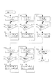
図1は、本発明の一実施例である増幅装置の構成を示すブロック図である。
本実施例の増幅装置1は、図1に示すように、携帯端末装置2と通信可能に成される。携帯端末装置2は、スマートフォンや携帯型パーソナルコンピュータ等から成る汎用の携帯情報端末である。
FIG. 1 is a block diagram showing a configuration of an amplifying apparatus according to an embodiment of the present invention.
As shown in FIG. 1, the amplification device 1 of the present embodiment is configured to be communicable with a mobile terminal device 2. The portable terminal device 2 is a general-purpose portable information terminal composed of a smartphone, a portable personal computer, or the like.

先ず、増幅装置1の構成について説明する。
図1に示すように、増幅装置1は、入力部11、チャンネル拡張部12、チャンネル切換部13、操作部14、制御部15、記録部16、表示部17、通信部18、第1のD/A変換部19a〜第5のD/A変換部19e、第1の増幅部20a〜第5の増幅部20e及び第1の出力端子21a〜第5の出力端子21eを備える。
First, the configuration of the amplification device 1 will be described.
As shown in FIG. 1, the amplifying apparatus 1 includes an input unit 11, a channel expansion unit 12, a channel switching unit 13, an operation unit 14, a control unit 15, a recording unit 16, a display unit 17, a communication unit 18, a first D / A conversion unit 19a to fifth D / A conversion unit 19e, first amplification unit 20a to fifth amplification unit 20e, and first output terminal 21a to fifth output terminal 21e.

入力部11は、再生装置(図示しない)から5.1チャンネルのマルチチャンネルデジタル信号を入力する。チャンネル拡張部12は、入力部11が入力したマルチチャンネルデジタル信号をLチャンネル、Cチャンネル、Rチャンネル、Lsチャンネル及びRsチャンネルの5つのチャンネルのデジタル信号に拡張する。なお、通常の5.1チャンネルのマルチチャンネルの場合、サブウーハ(Sub woofer)スピーカによって放音を行うためのLFEチャンネルのデジタル信号も含まれるが、本実施例においては、このLFEチャンネルのデジタル信号及びサブウーハスピーカの説明は省略するものとする。   The input unit 11 inputs a 5.1 channel multi-channel digital signal from a playback device (not shown). The channel expansion unit 12 expands the multi-channel digital signal input by the input unit 11 to a digital signal of five channels of L channel, C channel, R channel, Ls channel, and Rs channel. In the case of a normal 5.1-channel multi-channel, an LFE channel digital signal for sound emission by a sub woofer speaker is also included, but in this embodiment, the LFE channel digital signal and The description of the subwoofer speaker is omitted.

チャンネル切換部13は、制御部15の制御に応じて、チャンネル拡張部12によって拡張された5つのチャンネルのデジタル信号を第1のD/A変換部19a〜第5のD/A変換部19eにそれぞれ振り分けて出力する。第1のD/A変換部19a〜第5のD/A変換部19eは、それぞれ入力されたデジタル信号をアナログ信号に変換し、変換したアナログ信号をそれぞれ第1のD/A変換部19a〜第5のD/A変換部19eに出力する。第1の増幅部20a〜第5の増幅部20eは、それぞれ入力されたアナログ信号を増幅し、増幅したアナログ信号をそれぞれ第1の出力端子21a〜第5の出力端子21eに出力する。   Under the control of the control unit 15, the channel switching unit 13 sends the digital signals of the five channels expanded by the channel expansion unit 12 to the first D / A conversion unit 19 a to the fifth D / A conversion unit 19 e. Sort and output each. The first D / A converter 19a to the fifth D / A converter 19e convert the inputted digital signals into analog signals, respectively, and convert the converted analog signals to the first D / A converters 19a to 19a, respectively. The data is output to the fifth D / A converter 19e. The first amplifying unit 20a to the fifth amplifying unit 20e amplify the input analog signals, and output the amplified analog signals to the first output terminal 21a to the fifth output terminal 21e, respectively.

第1の出力端子21a〜第5の出力端子21eは、それぞれLチャンネル用スピーカ、Cチャンネル用スピーカ、Rチャンネル用スピーカ、Lsチャンネル用スピーカ及びRsチャンネル用スピーカのいずれかのスピーカに任意に接続されている。   The first output terminal 21a to the fifth output terminal 21e are arbitrarily connected to any one of an L channel speaker, a C channel speaker, an R channel speaker, an Ls channel speaker, and an Rs channel speaker, respectively. ing.

操作部14は、音量ボリューム、再生ソース選択キー等を備え、それらが操作されることによって制御部15に指示信号を出力する。制御部15は、操作部14からの指示信号に応じて第1の増幅部20a〜第5の増幅部20eによるアナログ信号の増幅度を変更したり、図示しないが前述した再生装置以外の装置から入力したデジタル信号の処理を行うように再生ソースの切換え等を行う。表示部17は、増幅装置1の動作状態の表示や、再生するソースの表示等を行う。   The operation unit 14 includes a sound volume, a reproduction source selection key, and the like, and outputs an instruction signal to the control unit 15 by operating them. The control unit 15 changes the amplification degree of the analog signal by the first amplification unit 20a to the fifth amplification unit 20e according to the instruction signal from the operation unit 14, or from a device other than the above-described playback device (not shown). The playback source is switched so that the input digital signal is processed. The display unit 17 displays the operation state of the amplifying apparatus 1 and the source to be reproduced.

通信部18は、制御部15の制御に応じて、Wi-Fi(ワイファイ、Wireless Fidelity)の無線手段によって携帯端末装置2などの他の装置と相互に情報通信を行う。記録部16は、制御部15の制御に基づいて、通信部18による相互情報通信よって携帯端末装置2から入力した情報データを記録する。また、記録部16は、予め、テスト音のデータ信号から成るテスト信号が記録されている。制御部15は、携帯端末装置2から入力され記録部16に記録された情報データ記録部16に基づいて、チャンネル拡張部12によって拡張された5つのチャンネルのデジタル信号を第1のD/A変換部19a〜第5のD/A変換部19eにそれぞれ振り分けて出力するようチャンネル切換部13を制御する。制御部15は、後述するスピーカの接続設定を行う場合、記録部16に記録したテスト信号を第1の出力端子21a〜第5の出力端子21eのいずれかの出力端子から出力するようチャンネル切換部13を制御する。   The communication unit 18 performs information communication with other devices such as the mobile terminal device 2 by wireless means of Wi-Fi (Wireless Fidelity) under the control of the control unit 15. The recording unit 16 records information data input from the mobile terminal device 2 through mutual information communication by the communication unit 18 based on the control of the control unit 15. The recording unit 16 records a test signal including a test sound data signal in advance. Based on the information data recording unit 16 input from the mobile terminal device 2 and recorded in the recording unit 16, the control unit 15 performs first D / A conversion on the digital signals of the five channels expanded by the channel expansion unit 12. The channel switching unit 13 is controlled so as to be distributed and output to each of the unit 19a to the fifth D / A conversion unit 19e. When performing connection setting of a speaker, which will be described later, the control unit 15 outputs a test signal recorded in the recording unit 16 from any one of the first output terminal 21a to the fifth output terminal 21e. 13 is controlled.

次に、携帯端末装置2の構成について説明する。
携帯端末装置2は、通信部22、制御部23、アプリケーション記録部24及び表示選択部25を備える。
Next, the configuration of the mobile terminal device 2 will be described.
The mobile terminal device 2 includes a communication unit 22, a control unit 23, an application recording unit 24, and a display selection unit 25.

通信部22は、Wi-Fi(ワイファイ、Wireless Fidelity)の無線手段によって増幅装置1などの他の装置と相互に情報通信を行う。制御部23は、通信部22、アプリケーション記録部24及び表示選択部25等の携帯端末装置2の全体を制御する。アプリケーション記録部24は、通信部22による通信手段や図示しない信号入力部を介して入力したアプリケーションソフトウェア(Application software)を記録する。   The communication unit 22 performs information communication with other devices such as the amplification device 1 by wireless means of Wi-Fi (Wireless Fidelity). The control unit 23 controls the entire mobile terminal device 2 such as the communication unit 22, the application recording unit 24, and the display selection unit 25. The application recording unit 24 records application software (Application software) input via a communication means by the communication unit 22 or a signal input unit (not shown).

表示選択部25は、タッチパネルから成り、アプリケーション記録部24に記録されたアプリーションソフトウェアが起動された場合、起動されたソフトウェアに応じた情報表示や各種選択キーの表示を行い、また、表示した各種選択キーがタッチされると、当該選択キーが選択されたことを検知し、各種選択信号を制御部23に出力する。   The display selection unit 25 includes a touch panel. When the application software recorded in the application recording unit 24 is activated, the display selection unit 25 displays information and various selection keys according to the activated software. When the selection key is touched, it is detected that the selection key is selected, and various selection signals are output to the control unit 23.

図2は、本実施例の携帯端末装置2において、増幅装置1の設定に関するアプリケーションソフトウェアを起動した場合の表示選択部25による画面表示の一例を示す図である。
なお、本実施例においては、携帯端末装置2のアプリケーション記録部24には、通信部22または図示しない信号入力によって、増幅装置1の設定に関するアプリケーションソフトウェアが予め記録されているものとする。
FIG. 2 is a diagram illustrating an example of a screen display by the display selection unit 25 when the application software related to the setting of the amplification device 1 is activated in the mobile terminal device 2 of the present embodiment.
In this embodiment, it is assumed that application software related to the setting of the amplifying apparatus 1 is recorded in advance in the application recording unit 24 of the mobile terminal device 2 by the communication unit 22 or a signal input (not shown).

携帯端末装置2において、予めアプリケーション記録部24に記録されている増幅装置1の設定に関するアプリケーションソフトウェアを起動すると、図2に示すように、表示選択部25には、ユーザ位置表示210、Cチャンネル選択キー211、Lチャンネル選択キー212、Rチャンネル選択キー213、Lsチャンネル選択キー214、Rsチャンネル選択キー215、スピーカ無し選択キー216及び設定スタートキー217が表示される。   When the application software related to the setting of the amplification device 1 recorded in advance in the application recording unit 24 is activated in the mobile terminal device 2, as shown in FIG. 2, the display selection unit 25 displays a user position display 210, C channel selection. A key 211, an L channel selection key 212, an R channel selection key 213, an Ls channel selection key 214, an Rs channel selection key 215, a speakerless selection key 216, and a setting start key 217 are displayed.

図2に示すように、ユーザ位置表示210は表示選択部25の中央部分に配置され、Cチャンネル選択キー211は表示選択部25の上方の中央部分、Lチャンネル選択キー212は表示選択部25の左側上方部分、Rチャンネル選択キー213は表示選択部25の右側上方部分、Lsチャンネル選択キー214は表示選択部25の左側下方部分、Rsチャンネル選択キー215は表示選択部25の右側下方部分にそれぞれ配置される。スピーカ無し選択キー216及び設定スタートキー217は、表示選択部25の任意の位置に配置される。   As shown in FIG. 2, the user position display 210 is arranged in the central portion of the display selection unit 25, the C channel selection key 211 is the central portion above the display selection unit 25, and the L channel selection key 212 is the display selection unit 25. The upper left part, the R channel selection key 213 is the upper right part of the display selection unit 25, the Ls channel selection key 214 is the lower left part of the display selection unit 25, and the Rs channel selection key 215 is the lower right part of the display selection unit 25. Be placed. The no-speaker selection key 216 and the setting start key 217 are arranged at arbitrary positions on the display selection unit 25.

図3は、本実施例の増幅装置1において、ユーザがLチャンネル用スピーカ、Cチャンネル用スピーカ、Rチャンネル用スピーカ、Lsチャンネル用スピーカ及びRsチャンネル用スピーカの5つのスピーカによって5.1チャンネル構成のマルチチャンネル再生を行う状態を示す図である。
本実施例においては、上方向をユーザの前方とし、右方向及び左方向をそれぞれユーザの右側及び左側とする。
FIG. 3 shows the amplification device 1 according to the present embodiment, in which the user has a 5.1 channel configuration with five speakers: an L channel speaker, a C channel speaker, an R channel speaker, an Ls channel speaker, and an Rs channel speaker. It is a figure which shows the state which performs multichannel reproduction | regeneration.
In this embodiment, the upper direction is the front of the user, and the right direction and the left direction are the right side and the left side of the user, respectively.

通常、増幅装置1と接続された5つのスピーカによって5.1チャンネルのマルチチャンネル再生を行う場合は、図3に示すように、ユーザ10の前方中央の位置にCチャンネルスピーカ101を配置し、また、ユーザ10の左側前方の位置にLチャンネルスピーカ102、ユーザ10の右側前方の位置にRチャンネルスピーカ103、ユーザ10の左側後方の位置にLsチャンネルスピーカ104、ユーザ10の右側後方の位置にRsチャンネルスピーカ105をそれぞれ配置する。   In general, when 5.1 channels of multi-channel reproduction is performed by five speakers connected to the amplification device 1, as shown in FIG. 3, a C channel speaker 101 is arranged at the front center position of the user 10, and The L channel speaker 102 is located at the left front position of the user 10, the R channel speaker 103 is located at the right front position of the user 10, the Ls channel speaker 104 is located at the left rear position of the user 10, and the Rs channel is located at the right rear position of the user 10. Speakers 105 are arranged respectively.

図4は、本実施例の増幅装置1によってマルチチャンネル再生を行う場合において、各スピーカに各チャンネルを割り当てる接続設定の動作を示すフローチャート図である。   FIG. 4 is a flowchart showing the connection setting operation for assigning each channel to each speaker when multi-channel reproduction is performed by the amplifying apparatus 1 of this embodiment.

本実施例においては、前述したように、図1に示す第1の出力端子21a〜第5の出力端子21eは、それぞれ図3に示すCチャンネルスピーカ101、Lチャンネルスピーカ102、Rチャンネルスピーカ103、Lsチャンネルスピーカ104及びRsチャンネルスピーカ105のいずれかのスピーカに任意に接続されているものとし、また、図3に示すように、携帯端末装置2はユーザ10が手で保持しているものとする。   In the present embodiment, as described above, the first output terminal 21a to the fifth output terminal 21e shown in FIG. 1 are respectively the C channel speaker 101, the L channel speaker 102, the R channel speaker 103, and the like shown in FIG. It is assumed that any of the Ls channel speaker 104 and the Rs channel speaker 105 is arbitrarily connected, and the mobile terminal device 2 is held by the user 10 as shown in FIG. .

先ず、携帯端末装置2によって、アプリケーション記録部24に記録されている増幅装置1の設定に関するアプリケーションソフトウェアを起動し、図3に示す表示を表示選択部25に表示する。   First, the mobile terminal device 2 starts application software related to the setting of the amplification device 1 recorded in the application recording unit 24, and displays the display shown in FIG.

次に、図3に示すように、ユーザ10の周囲に各スピーカが配置された状態において、表示選択部25の設定スタートキー217が選択されると(スタート)、表示選択部25は、設定スタートキー217が選択されたことを示す信号を制御部23に出力する。制御部23は、表示選択部25から設定スタートキー217が選択されたことを示す信号が出力されると、設定スタートを示す信号を増幅装置1の通信部18に送信するよう通信部22を制御する。通信部22は、制御部23の制御に応じて設定スタートを示す信号を通信部18に送信する。   Next, as shown in FIG. 3, when the setting start key 217 of the display selection unit 25 is selected (start) in a state where the speakers are arranged around the user 10, the display selection unit 25 starts the setting start. A signal indicating that the key 217 has been selected is output to the control unit 23. When the signal indicating that the setting start key 217 is selected is output from the display selection unit 25, the control unit 23 controls the communication unit 22 to transmit a signal indicating the setting start to the communication unit 18 of the amplification device 1. To do. The communication unit 22 transmits a signal indicating setting start to the communication unit 18 in accordance with the control of the control unit 23.

通信部18は、通信部22から設定スタートを示す信号を受信すると、設定スタートを示す信号を制御部15に出力する。制御部15は、通信部18から設定スタートを示す信号が出力されると、記録部16に記録されているテスト信号を第1の出力端子21aから出力するようチャンネル切換部13を制御する。チャンネル切換部13は、制御部15の制御に応じて記録部16に記録されたテスト信号を第1の出力端子21aから出力する(ステップS1)。次に、制御部15は、通信部22及び通信部18を介して携帯端末装置2からチャンネルに関する情報信号が受信されるまで待機する(ステップS2)。   When receiving a signal indicating the setting start from the communication unit 22, the communication unit 18 outputs a signal indicating the setting start to the control unit 15. When the signal indicating the setting start is output from the communication unit 18, the control unit 15 controls the channel switching unit 13 to output the test signal recorded in the recording unit 16 from the first output terminal 21a. The channel switching unit 13 outputs the test signal recorded in the recording unit 16 from the first output terminal 21a under the control of the control unit 15 (step S1). Next, the control unit 15 waits until an information signal regarding the channel is received from the mobile terminal device 2 via the communication unit 22 and the communication unit 18 (step S2).

図3に示すように、ユーザ10の周囲に各スピーカが配置されている状態において、第1の出力端子21aと接続されたスピーカからテスト信号が出力されると、ユーザ10は、図2に示すように表示選択部25に表示された画面を目視しながら、Cチャンネルスピーカ101〜Rsチャンネルスピーカ105の内、どの方向のスピーカからテスト信号が出力されているかを確認し、表示選択部25に表示されたCチャンネル選択キー211〜Rsチャンネル選択キー215の内、当該テスト信号が出力された方向のスピーカに該当するスピーカの選択キーをタッチして選択する。   As shown in FIG. 3, when a test signal is output from the speaker connected to the first output terminal 21 a in a state where the speakers are arranged around the user 10, the user 10 is shown in FIG. 2. In this way, while observing the screen displayed on the display selection unit 25, it is confirmed from which direction the test signal is output from among the C channel speakers 101 to Rs channel speaker 105, and displayed on the display selection unit 25. Among the C channel selection keys 211 to Rs channel selection keys 215, the speaker selection key corresponding to the speaker in the direction in which the test signal is output is touched for selection.

本実施例においては、図1に示す第1の出力端子21aと図3に示すRsチャンネルスピーカ105が接続されているものとし、このとき、Rsチャンネルスピーカ105からテスト信号が出力され、ユーザ10によってRsチャンネル選択キー215が選択されたものとする。   In this embodiment, it is assumed that the first output terminal 21a shown in FIG. 1 and the Rs channel speaker 105 shown in FIG. 3 are connected. At this time, a test signal is output from the Rs channel speaker 105. Assume that the Rs channel selection key 215 is selected.

表示選択部25は、Rsチャンネル選択キー215が選択されたことを示す信号を制御部23に出力する。制御部23は、表示選択部25からRsチャンネル選択キー215が選択されたことを示す信号が出力されると、Rsチャンネルを示す情報信号を増幅装置1の通信部18に送信するよう通信部22を制御する。通信部22は、制御部23の制御に応じてRsチャンネルを示す情報信号を通信部18に送信する。   The display selection unit 25 outputs a signal indicating that the Rs channel selection key 215 has been selected to the control unit 23. When a signal indicating that the Rs channel selection key 215 has been selected is output from the display selection unit 25, the control unit 23 transmits an information signal indicating the Rs channel to the communication unit 18 of the amplifying apparatus 1. To control. The communication unit 22 transmits an information signal indicating the Rs channel to the communication unit 18 under the control of the control unit 23.

通信部18は、通信部22からRsチャンネルを示す情報信号を受信すると、このRsチャンネルを示す情報信号を制御部15に出力する。制御部15は、通信部18から出力されたRsチャンネルを示す情報信号が出力されると、このときにテスト信号を出力した第1の出力端子21aの情報と共に、通信部18から出力されたRsチャンネルを示す情報を記録部16に記録し(ステップS3)、ステップS4に移行する。   When receiving the information signal indicating the Rs channel from the communication unit 22, the communication unit 18 outputs the information signal indicating the Rs channel to the control unit 15. When the information signal indicating the Rs channel output from the communication unit 18 is output, the control unit 15 outputs the Rs output from the communication unit 18 together with the information of the first output terminal 21a that output the test signal at this time. Information indicating the channel is recorded in the recording unit 16 (step S3), and the process proceeds to step S4.

ステップS4において、制御部15は、通記録部16に記録されているテスト信号を第2の出力端子21bから出力するようチャンネル切換部13を制御する。チャンネル切換部13は、制御部15の制御に応じて記録部16に記録されたテスト信号を第2の出力端子21bから出力する。次に、制御部15は、通信部22及び通信部18を介して携帯端末装置2からチャンネルに関する情報信号が受信されるまで待機する(ステップS5)。   In step S4, the control unit 15 controls the channel switching unit 13 to output the test signal recorded in the recording unit 16 from the second output terminal 21b. The channel switching unit 13 outputs the test signal recorded in the recording unit 16 from the second output terminal 21b under the control of the control unit 15. Next, the control unit 15 waits until an information signal regarding the channel is received from the mobile terminal device 2 via the communication unit 22 and the communication unit 18 (step S5).

図3に示すように、ユーザ10の周囲に各スピーカが配置されている状態において、第2の出力端子21bと接続されたスピーカからテスト信号が出力されると、ユーザ10は、図2に示すように表示選択部25に表示された画面を目視しながら、Cチャンネルスピーカ101〜Rsチャンネルスピーカ105の内、どの方向のスピーカからテスト信号が出力されているかを確認し、表示選択部25に表示されたCチャンネル選択キー211〜Rsチャンネル選択キー215の内、当該テスト信号が出力された方向のスピーカに該当するスピーカの選択キーをタッチして選択する。   As shown in FIG. 3, when a test signal is output from a speaker connected to the second output terminal 21 b in a state where the speakers are arranged around the user 10, the user 10 is shown in FIG. 2. In this way, while observing the screen displayed on the display selection unit 25, it is confirmed from which direction the test signal is output from among the C channel speakers 101 to Rs channel speaker 105, and displayed on the display selection unit 25. Among the C channel selection keys 211 to Rs channel selection keys 215, the speaker selection key corresponding to the speaker in the direction in which the test signal is output is touched for selection.

本実施例においては、図1に示す第2の出力端子21bと図3に示すLsチャンネルスピーカ104が接続されているものとし、このとき、Lsチャンネルスピーカ104からテスト信号が出力され、ユーザ10によってLsチャンネル選択キー214が選択されたものとする。   In this embodiment, it is assumed that the second output terminal 21b shown in FIG. 1 and the Ls channel speaker 104 shown in FIG. 3 are connected. At this time, a test signal is output from the Ls channel speaker 104. It is assumed that the Ls channel selection key 214 has been selected.

表示選択部25は、Lsチャンネル選択キー214が選択されたことを示す信号を制御部23に出力する。制御部23は、表示選択部25からLsチャンネル選択キー214が選択されたことを示す信号が出力されると、Lsチャンネルを示す情報信号を増幅装置1の通信部18に送信するよう通信部22を制御する。通信部22は、制御部23の制御に応じてLsチャンネルを示す情報信号を通信部18に送信する。   The display selection unit 25 outputs a signal indicating that the Ls channel selection key 214 has been selected to the control unit 23. When the signal indicating that the Ls channel selection key 214 has been selected is output from the display selection unit 25, the control unit 23 transmits an information signal indicating the Ls channel to the communication unit 18 of the amplification device 1. To control. The communication unit 22 transmits an information signal indicating the Ls channel to the communication unit 18 under the control of the control unit 23.

通信部18は、通信部22からLsチャンネルを示す情報信号を受信すると、このLsチャンネルを示す情報信号を制御部15に出力する。制御部15は、通信部18から出力されたLsチャンネルを示す情報信号が出力されると、このときにテスト信号を出力した第2の出力端子21bの情報と共に、通信部18から出力されたLsチャンネルを示す情報を記録部16に記録し(ステップS6)、ステップS7に移行する。   When receiving the information signal indicating the Ls channel from the communication unit 22, the communication unit 18 outputs the information signal indicating the Ls channel to the control unit 15. When the information signal indicating the Ls channel output from the communication unit 18 is output, the control unit 15 outputs the Ls output from the communication unit 18 together with the information of the second output terminal 21b that output the test signal at this time. Information indicating the channel is recorded in the recording unit 16 (step S6), and the process proceeds to step S7.

ステップS7において、制御部15は、通記録部16に記録されているテスト信号を第3の出力端子21cから出力するようチャンネル切換部13を制御する。チャンネル切換部13は、制御部15の制御に応じて記録部16に記録されたテスト信号を第3の出力端子21cから出力する。次に、制御部15は、通信部22及び通信部18を介して携帯端末装置2からチャンネルに関する情報信号が受信されるまで待機する(ステップS8)。   In step S7, the control unit 15 controls the channel switching unit 13 to output the test signal recorded in the recording unit 16 from the third output terminal 21c. The channel switching unit 13 outputs the test signal recorded in the recording unit 16 from the third output terminal 21 c under the control of the control unit 15. Next, the control unit 15 waits until an information signal regarding a channel is received from the mobile terminal device 2 via the communication unit 22 and the communication unit 18 (step S8).

図3に示すように、ユーザ10の周囲に各スピーカが配置されている状態において、第3の出力端子21cと接続されたスピーカからテスト信号が出力されると、ユーザ10は、図2に示すように表示選択部25に表示された画面を目視しながら、Cチャンネルスピーカ101〜Rsチャンネルスピーカ105の内、どの方向のスピーカからテスト信号が出力されているかを確認し、表示選択部25に表示されたCチャンネル選択キー211〜Rsチャンネル選択キー215の内、当該テスト信号が出力された方向のスピーカに該当するスピーカの選択キーをタッチして選択する。   As shown in FIG. 3, when a test signal is output from the speaker connected to the third output terminal 21 c in a state where the speakers are arranged around the user 10, the user 10 is shown in FIG. 2. In this way, while observing the screen displayed on the display selection unit 25, it is confirmed from which direction the test signal is output from among the C channel speakers 101 to Rs channel speaker 105, and displayed on the display selection unit 25. Among the C channel selection keys 211 to Rs channel selection keys 215, the speaker selection key corresponding to the speaker in the direction in which the test signal is output is touched for selection.

本実施例においては、図1に示す第3の出力端子21cと図3に示すRチャンネルスピーカ103が接続されているものとし、このとき、Rチャンネルスピーカ103からテスト信号が出力され、ユーザ10によってRチャンネル選択キー213が選択されたものとする。   In this embodiment, the third output terminal 21c shown in FIG. 1 and the R channel speaker 103 shown in FIG. 3 are connected. At this time, a test signal is output from the R channel speaker 103 and Assume that the R channel selection key 213 is selected.

表示選択部25は、Rチャンネル選択キー213が選択されたことを示す信号を制御部23に出力する。制御部23は、表示選択部25からRチャンネル選択キー213が選択されたことを示す信号が出力されると、Rチャンネルを示す情報信号を増幅装置1の通信部18に送信するよう通信部22を制御する。通信部22は、制御部23の制御に応じてRチャンネルを示す情報信号を通信部18に送信する。   The display selection unit 25 outputs a signal indicating that the R channel selection key 213 has been selected to the control unit 23. When the signal indicating that the R channel selection key 213 is selected is output from the display selection unit 25, the control unit 23 transmits the information signal indicating the R channel to the communication unit 18 of the amplification device 1. To control. The communication unit 22 transmits an information signal indicating the R channel to the communication unit 18 under the control of the control unit 23.

通信部18は、通信部22からRチャンネルを示す情報信号を受信すると、このRチャンネルを示す情報信号を制御部15に出力する。制御部15は、通信部18から出力されたRチャンネルを示す情報信号が出力されると、このときにテスト信号を出力した第3の出力端子21cの情報と共に、通信部18から出力されたRチャンネルを示す情報を記録部16に記録し(ステップS9)、ステップS10に移行する。   When receiving the information signal indicating the R channel from the communication unit 22, the communication unit 18 outputs the information signal indicating the R channel to the control unit 15. When the information signal indicating the R channel output from the communication unit 18 is output, the control unit 15 outputs the R signal output from the communication unit 18 together with the information of the third output terminal 21c that output the test signal at this time. Information indicating the channel is recorded in the recording unit 16 (step S9), and the process proceeds to step S10.

ステップS10において、制御部15は、通記録部16に記録されているテスト信号を第4の出力端子21dから出力するようチャンネル切換部13を制御する。チャンネル切換部13は、制御部15の制御に応じて記録部16に記録されたテスト信号を第4の出力端子21dから出力する。次に、制御部15は、通信部22及び通信部18を介して携帯端末装置2からチャンネルに関する情報信号が受信されるまで待機する(ステップS11)。   In step S10, the control unit 15 controls the channel switching unit 13 to output the test signal recorded in the recording unit 16 from the fourth output terminal 21d. The channel switching unit 13 outputs the test signal recorded in the recording unit 16 from the fourth output terminal 21 d under the control of the control unit 15. Next, the control unit 15 waits until an information signal regarding a channel is received from the mobile terminal device 2 via the communication unit 22 and the communication unit 18 (step S11).

図3に示すように、ユーザ10の周囲に各スピーカが配置されている状態において、第4の出力端子21dと接続されたスピーカからテスト信号が出力されると、ユーザ10は、図2に示すように表示選択部25に表示された画面を目視しながら、Cチャンネルスピーカ101〜Rsチャンネルスピーカ105の内、どの方向のスピーカからテスト信号が出力されているかを確認し、表示選択部25に表示されたCチャンネル選択キー211〜Rsチャンネル選択キー215の内、当該テスト信号が出力された方向のスピーカに該当するスピーカの選択キーをタッチして選択する。   As shown in FIG. 3, when a test signal is output from the speaker connected to the fourth output terminal 21 d in a state where the speakers are arranged around the user 10, the user 10 is shown in FIG. 2. In this way, while observing the screen displayed on the display selection unit 25, it is confirmed from which direction the test signal is output from among the C channel speakers 101 to Rs channel speaker 105, and displayed on the display selection unit 25. Among the C channel selection keys 211 to Rs channel selection keys 215, the speaker selection key corresponding to the speaker in the direction in which the test signal is output is touched for selection.

本実施例においては、図1に示す第4の出力端子21dと図3に示すLチャンネルスピーカ102が接続されているものとし、このとき、Lチャンネルスピーカ102からテスト信号が出力され、ユーザ10によってLチャンネル選択キー212が選択されたものとする。   In the present embodiment, it is assumed that the fourth output terminal 21d shown in FIG. 1 and the L channel speaker 102 shown in FIG. 3 are connected. At this time, a test signal is output from the L channel speaker 102 and Assume that the L channel selection key 212 is selected.

表示選択部25は、Lチャンネル選択キー212が選択されたことを示す信号を制御部23に出力する。制御部23は、表示選択部25からLチャンネル選択キー212が選択されたことを示す信号が出力されると、Lチャンネルを示す情報信号を増幅装置1の通信部18に送信するよう通信部22を制御する。通信部22は、制御部23の制御に応じてLチャンネルを示す情報信号を通信部18に送信する。   The display selection unit 25 outputs a signal indicating that the L channel selection key 212 has been selected to the control unit 23. When the signal indicating that the L channel selection key 212 is selected is output from the display selection unit 25, the control unit 23 transmits the information signal indicating the L channel to the communication unit 18 of the amplification device 1. To control. The communication unit 22 transmits an information signal indicating the L channel to the communication unit 18 under the control of the control unit 23.

通信部18は、通信部22からLチャンネルを示す情報信号を受信すると、このLチャンネルを示す情報信号を制御部15に出力する。制御部15は、通信部18から出力されたLチャンネルを示す情報信号が出力されると、このときにテスト信号を出力した第4の出力端子21dの情報と共に、通信部18から出力されたLチャンネルを示す情報を記録部16に記録し(ステップS12)、ステップS13に移行する。   When receiving the information signal indicating the L channel from the communication unit 22, the communication unit 18 outputs the information signal indicating the L channel to the control unit 15. When the information signal indicating the L channel output from the communication unit 18 is output, the control unit 15 outputs the L signal output from the communication unit 18 together with the information of the fourth output terminal 21d that output the test signal at this time. Information indicating the channel is recorded in the recording unit 16 (step S12), and the process proceeds to step S13.

ステップS13において、制御部15は、通記録部16に記録されているテスト信号を第5の出力端子21eから出力するようチャンネル切換部13を制御する。チャンネル切換部13は、制御部15の制御に応じて記録部16に記録されたテスト信号を第5の出力端子21eから出力する。次に、制御部15は、通信部22及び通信部18を介して携帯端末装置2からチャンネルに関する情報信号が受信されるまで待機する(ステップS14)。   In step S13, the control unit 15 controls the channel switching unit 13 to output the test signal recorded in the recording unit 16 from the fifth output terminal 21e. The channel switching unit 13 outputs the test signal recorded in the recording unit 16 from the fifth output terminal 21e under the control of the control unit 15. Next, the control unit 15 waits until an information signal regarding the channel is received from the mobile terminal device 2 via the communication unit 22 and the communication unit 18 (step S14).

図3に示すように、ユーザ10の周囲に各スピーカが配置されている状態において、第5の出力端子21eと接続されたスピーカからテスト信号が出力されると、ユーザ10は、図2に示すように表示選択部25に表示された画面を目視しながら、Cチャンネルスピーカ101〜Rsチャンネルスピーカ105の内、どの方向のスピーカからテスト信号が出力されているかを確認し、表示選択部25に表示されたCチャンネル選択キー211〜Rsチャンネル選択キー215の内、当該テスト信号が出力された方向のスピーカに該当するスピーカの選択キーをタッチして選択する。   As shown in FIG. 3, when a test signal is output from the speaker connected to the fifth output terminal 21 e in a state where the speakers are arranged around the user 10, the user 10 is shown in FIG. 2. In this way, while observing the screen displayed on the display selection unit 25, it is confirmed from which direction the test signal is output from among the C channel speakers 101 to Rs channel speaker 105, and displayed on the display selection unit 25. Among the C channel selection keys 211 to Rs channel selection keys 215, the speaker selection key corresponding to the speaker in the direction in which the test signal is output is touched for selection.

本実施例においては、図1に示す第5の出力端子21eと図3に示すCチャンネルスピーカ101が接続されているものとし、このとき、Cチャンネルスピーカ101からテスト信号が出力され、ユーザ10によってCチャンネル選択キー211が選択されたものとする。   In this embodiment, it is assumed that the fifth output terminal 21e shown in FIG. 1 and the C channel speaker 101 shown in FIG. 3 are connected. At this time, a test signal is output from the C channel speaker 101. It is assumed that the C channel selection key 211 is selected.

表示選択部25は、Cチャンネル選択キー211が選択されたことを示す信号を制御部23に出力する。制御部23は、表示選択部25からCチャンネル選択キー211が選択されたことを示す信号が出力されると、Cチャンネルを示す情報信号を増幅装置1の通信部18に送信するよう通信部22を制御する。通信部22は、制御部23の制御に応じてCチャンネルを示す情報信号を通信部18に送信する。   The display selection unit 25 outputs a signal indicating that the C channel selection key 211 has been selected to the control unit 23. When the signal indicating that the C channel selection key 211 has been selected is output from the display selection unit 25, the control unit 23 transmits the information signal indicating the C channel to the communication unit 18 of the amplifying apparatus 1. To control. The communication unit 22 transmits an information signal indicating the C channel to the communication unit 18 under the control of the control unit 23.

通信部18は、通信部22からCチャンネルを示す情報信号を受信すると、このCチャンネルを示す情報信号を制御部15に出力する。制御部15は、通信部18から出力されたCチャンネルを示す情報信号が出力されると、このときにテスト信号を出力した第5の出力端子21eの情報と共に、通信部18から出力されたCチャンネルを示す情報を記録部16に記録し(ステップS15)、ステップS16に移行する。   When receiving the information signal indicating the C channel from the communication unit 22, the communication unit 18 outputs the information signal indicating the C channel to the control unit 15. When the information signal indicating the C channel output from the communication unit 18 is output, the control unit 15 outputs the C signal output from the communication unit 18 together with the information of the fifth output terminal 21e that outputs the test signal at this time. Information indicating the channel is recorded in the recording unit 16 (step S15), and the process proceeds to step S16.

次に、制御部15は、記録部16に記録した各チャンネルを示す情報と、当該各チャンネルを示す情報と共に記録した出力端子の情報に基づいて、第1の出力端子21a〜第5の出力端子21eの各出力端子から出力するチャンネルを配置する。   Next, the control unit 15 selects the first output terminal 21a to the fifth output terminal based on the information indicating each channel recorded in the recording unit 16 and the information on the output terminals recorded together with the information indicating each channel. Channels to be output from the output terminals 21e are arranged.

本実施例においては、ステップS3において、第1の出力端子21aの情報と共にRsチャンネルを示す情報が記録部16に記録されていることにより、制御部15は、第1の出力端子21aからRsチャンネルの信号が出力されるようにチャンネル切換部13を制御する。チャンネル切換部13は、制御部15の制御に応じて、第1の出力端子21aからRsチャンネルが出力されるように、第1のD/A変換部19aにRsチャンネルのデジタル信号を出力するよう出力チャンネルを設定する。   In the present embodiment, in step S3, the information indicating the Rs channel is recorded in the recording unit 16 together with the information of the first output terminal 21a, so that the control unit 15 is connected to the Rs channel from the first output terminal 21a. The channel switching unit 13 is controlled so that the following signal is output. The channel switching unit 13 outputs a digital signal of the Rs channel to the first D / A conversion unit 19a so that the Rs channel is output from the first output terminal 21a according to the control of the control unit 15. Set the output channel.

また、本実施例においては、ステップS6において、第2の出力端子21bの情報と共にLsチャンネルを示す情報が記録部16に記録されていることにより、制御部15は、第2の出力端子21bからLsチャンネルの信号が出力されるようにチャンネル切換部13を制御する。チャンネル切換部13は、制御部15の制御に応じて、第2の出力端子21bからLsチャンネルが出力されるように、第2のD/A変換部19bにLsチャンネルのデジタル信号を出力するよう出力チャンネルを設定する。   Further, in this embodiment, in step S6, the information indicating the Ls channel is recorded in the recording unit 16 together with the information of the second output terminal 21b, so that the control unit 15 is connected to the second output terminal 21b. The channel switching unit 13 is controlled so that the Ls channel signal is output. The channel switching unit 13 outputs an Ls channel digital signal to the second D / A conversion unit 19b so that the Ls channel is output from the second output terminal 21b under the control of the control unit 15. Set the output channel.

また、本実施例においては、ステップS9において、第3の出力端子21cの情報と共にRチャンネルを示す情報が記録部16に記録されていることにより、制御部15は、第3の出力端子21cからRチャンネルの信号が出力されるようにチャンネル切換部13を制御する。チャンネル切換部13は、制御部15の制御に応じて、第3の出力端子21cからRチャンネルが出力されるように、第3のD/A変換部19cにRチャンネルのデジタル信号を出力するよう出力チャンネルを設定する。   Further, in this embodiment, in step S9, the information indicating the R channel is recorded in the recording unit 16 together with the information of the third output terminal 21c, so that the control unit 15 is connected to the third output terminal 21c. The channel switching unit 13 is controlled so that the R channel signal is output. The channel switching unit 13 outputs an R channel digital signal to the third D / A conversion unit 19c so that the R channel is output from the third output terminal 21c under the control of the control unit 15. Set the output channel.

また、本実施例においては、ステップS12において、第4の出力端子21dの情報と共にLチャンネルを示す情報が記録部16に記録されていることにより、制御部15は、第4の出力端子21dからLチャンネルの信号が出力されるようにチャンネル切換部13を制御する。チャンネル切換部13は、制御部15の制御に応じて、第4の出力端子21dからLチャンネルが出力されるように、第4のD/A変換部19dにLチャンネルのデジタル信号を出力するよう出力チャンネルを設定する。   Further, in the present embodiment, in step S12, the information indicating the L channel is recorded in the recording unit 16 together with the information of the fourth output terminal 21d, whereby the control unit 15 is connected to the fourth output terminal 21d. The channel switching unit 13 is controlled so that an L channel signal is output. The channel switching unit 13 outputs an L channel digital signal to the fourth D / A conversion unit 19d so that the L channel is output from the fourth output terminal 21d under the control of the control unit 15. Set the output channel.

また、本実施例においては、ステップS15において、第5の出力端子21eの情報と共にCチャンネルを示す情報が記録部16に記録されていることにより、制御部15は、第5の出力端子21eからCチャンネルの信号が出力されるようにチャンネル切換部13を制御する。チャンネル切換部13は、制御部15の制御に応じて、第5の出力端子21eからCチャンネルが出力されるように、第5のD/A変換部19eにCチャンネルのデジタル信号を出力するよう出力チャンネルを設定する。   In the present embodiment, in step S15, the information indicating the C channel is recorded in the recording unit 16 together with the information of the fifth output terminal 21e, so that the control unit 15 is connected to the fifth output terminal 21e. The channel switching unit 13 is controlled so that the C channel signal is output. The channel switching unit 13 outputs a C channel digital signal to the fifth D / A conversion unit 19e so that the C channel is output from the fifth output terminal 21e under the control of the control unit 15. Set the output channel.

以上のように、本実施例の増幅装置1は、第1の出力端子21a〜第5の出力端子21eの各出力端子から順番にテスト信号を出力し、このときテスト信号が出力されたスピーカがどのスピーカだったのかをユーザが確認し、図2に示すように表示選択部25に表示されたCチャンネル選択キー211〜Rsチャンネル選択キー215の中からテスト信号が出力されたスピーカに該当する方向のスピーカを選択することによって、各チャンネルのオーディオ信号を正確に各スピーカに出力するよう設定することができる。   As described above, the amplifying apparatus 1 according to the present embodiment sequentially outputs the test signals from the output terminals of the first output terminal 21a to the fifth output terminal 21e, and the speaker to which the test signal is output at this time is output. The user confirms which speaker it was and the direction corresponding to the speaker from which the test signal is output from among the C channel selection key 211 to Rs channel selection key 215 displayed on the display selection unit 25 as shown in FIG. By selecting these speakers, it is possible to set so that the audio signal of each channel is accurately output to each speaker.

このことにより、本実施例の増幅装置1は、チャンネル毎に割り当てられたスピーカを各出力端子と正確に接続しておかなくても、各出力端子と各スピーカをランダムに接続した後、前述したように、表示選択部25に表示された設定スタートキー217を選択し、表示選択部25に表示されたCチャンネル選択キー211〜Rsチャンネル選択キー215の中からテスト信号が出力されたスピーカに該当する方向のスピーカを選択するだけで各スピーカのチャンネルを容易かつ正確に自動設定することができる。   As a result, the amplifying apparatus 1 according to the present embodiment described above after randomly connecting each output terminal and each speaker without accurately connecting the speaker assigned to each channel to each output terminal. As described above, the setting start key 217 displayed on the display selection unit 25 is selected, and the C channel selection key 211 to Rs channel selection key 215 displayed on the display selection unit 25 correspond to the speaker from which the test signal is output. The channel of each speaker can be automatically set easily and accurately simply by selecting the speaker in the direction in which it is to be performed.

図5は、本実施例の増幅装置1において、ユーザがLチャンネル用スピーカ、Rチャンネル用スピーカ、Lsチャンネル用スピーカ及びRsチャンネル用スピーカの4つのスピーカによって5.1チャンネル構成のマルチチャンネル再生を行う状態を示す図である。
本実施例においては、上方向をユーザの前方とし、右方向及び左方向をそれぞれユーザの右側及び左側とする。
FIG. 5 shows that in the amplifying apparatus 1 according to the present embodiment, the user performs 5.1 channel multi-channel reproduction using four speakers, an L channel speaker, an R channel speaker, an Ls channel speaker, and an Rs channel speaker. It is a figure which shows a state.
In this embodiment, the upper direction is the front of the user, and the right direction and the left direction are the right side and the left side of the user, respectively.

通常、増幅装置1と接続された4つのスピーカによって5.1チャンネル構成のマルチチャンネル再生を行う場合は、図5に示すように、ユーザ10の左側前方の位置にLチャンネルスピーカ102を配設し、ユーザ10の右側前方の位置にRチャンネルスピーカ103、ユーザ10の左側後方の位置にLsチャンネルスピーカ104、ユーザ10の右側後方の位置にRsチャンネルスピーカ105をそれぞれ配置する。   Normally, when 5.1 channel multi-channel playback is performed by four speakers connected to the amplifying apparatus 1, an L channel speaker 102 is disposed at the front left position of the user 10 as shown in FIG. The R channel speaker 103 is disposed at a position on the right front side of the user 10, the Ls channel speaker 104 is disposed on the left rear position of the user 10, and the Rs channel speaker 105 is disposed on the right rear side of the user 10.

この場合、図4のフローチャート図に沿って前述して説明したのと同様に、ステップS1〜ステップS16までの動作によって各スピーカに各チャンネルを割り当てる接続設定を行うが、図5に示すようにCチャンネルのスピーカが省略され、例えば、Cチャンネル用スピーカを除く4つのスピーカが第1の出力端子21a〜第4の出力端子21dの4つの出力端子に任意に接続され、第5の出力端子21eにスピーカが接続されていない場合、図4のフローチャート図のステップS13〜ステップS15における動作が次のようになる。   In this case, as described above with reference to the flowchart of FIG. 4, connection setting for assigning each channel to each speaker is performed by the operation from step S1 to step S16. However, as shown in FIG. The channel speakers are omitted, for example, four speakers excluding the C channel speaker are arbitrarily connected to the four output terminals of the first output terminal 21a to the fourth output terminal 21d, and are connected to the fifth output terminal 21e. When the speaker is not connected, the operation in steps S13 to S15 in the flowchart of FIG. 4 is as follows.

ステップS13において、制御部15は、通記録部16に記録されているテスト信号を第5の出力端子21eから出力するようチャンネル切換部13を制御する。チャンネル切換部13は、制御部15の制御に応じて記録部16に記録されたテスト信号を第5の出力端子21eから出力する。次に、制御部15は、通信部22及び通信部18を介して携帯端末装置2からチャンネルに関する情報信号が受信されるまで待機する(ステップS14)。   In step S13, the control unit 15 controls the channel switching unit 13 to output the test signal recorded in the recording unit 16 from the fifth output terminal 21e. The channel switching unit 13 outputs the test signal recorded in the recording unit 16 from the fifth output terminal 21e under the control of the control unit 15. Next, the control unit 15 waits until an information signal regarding the channel is received from the mobile terminal device 2 via the communication unit 22 and the communication unit 18 (step S14).

図5に示すように、ユーザ10の周囲に各スピーカが配置されている状態において、第5の出力端子21eにスピーカが接続されていない場合であって、図5に示す各スピーカの中のどのスピーカからもテスト信号が出力されない場合、ユーザ10は、図2に示す表示選択部25に表示されたスピーカ無し選択キー216をタッチして選択する。   As shown in FIG. 5, in the state where each speaker is arranged around the user 10, there is no speaker connected to the fifth output terminal 21 e, which of the speakers shown in FIG. When the test signal is not output from the speaker, the user 10 touches and selects the no speaker selection key 216 displayed on the display selection unit 25 shown in FIG.

表示選択部25は、スピーカ無し選択キー216が選択されたことを示す信号を制御部23に出力する。制御部23は、表示選択部25からスピーカ無し選択キー216が選択されたことを示す信号が出力されると、スピーカが無いことを示す情報信号を増幅装置1の通信部18に送信するよう通信部22を制御する。通信部22は、制御部23の制御に応じてスピーカが無いことを示す情報信号を通信部18に送信する。   The display selection unit 25 outputs a signal indicating that the speakerless selection key 216 has been selected to the control unit 23. When the signal indicating that the speaker selection key 216 is selected is output from the display selection unit 25, the control unit 23 performs communication so as to transmit an information signal indicating that there is no speaker to the communication unit 18 of the amplification device 1. The unit 22 is controlled. The communication unit 22 transmits an information signal indicating that there is no speaker to the communication unit 18 under the control of the control unit 23.

通信部18は、通信部22からスピーカが無いことを示す情報信号を受信すると、このスピーカが無いことを示す情報信号を制御部15に出力する。制御部15は、通信部18から出力されたスピーカが無いことを示す情報信号が出力されると、このときにテスト信号を出力した第5の出力端子21eの情報と共に、通信部18から出力されたスピーカが無いことを示す情報を記録部16に記録し(ステップS15)、ステップS16に移行する。   When receiving the information signal indicating that there is no speaker from the communication unit 22, the communication unit 18 outputs the information signal indicating that there is no speaker to the control unit 15. When the information signal indicating that there is no speaker output from the communication unit 18 is output, the control unit 15 is output from the communication unit 18 together with the information of the fifth output terminal 21e that output the test signal at this time. The information indicating that there is no speaker is recorded in the recording unit 16 (step S15), and the process proceeds to step S16.

次に、制御部15は、記録部16に記録した各チャンネルを示す情報と、当該各チャンネルを示す情報と共に記録した出力端子の情報に基づいて、第1の出力端子21a〜第5の出力端子21eの各出力端子から出力するチャンネルを配置する。   Next, the control unit 15 selects the first output terminal 21a to the fifth output terminal based on the information indicating each channel recorded in the recording unit 16 and the information on the output terminals recorded together with the information indicating each channel. Channels to be output from the output terminals 21e are arranged.

本実施例においては、ステップS15において、第5の出力端子21eの情報と共にスピーカが無いことを示す情報が記録部16に記録されていることにより、制御部15は、第5の出力端子21eにスピーカが接続されていない情報を検出すると共に、ステップS3、ステップS6、ステップS9及びステップS12において記録部16に記録した各出力端子の情報と共に記録されている各チャンネルを示す情報に基づいて、Cチャンネル選択キー211が選択されていないことを検出する。制御部15は、検出した第5の出力端子21eにスピーカが接続されていない情報と、Cチャンネル選択キー211が選択されていない情報に基づいて、Lチャンネルを示す情報と共に記録部16に記録されている出力端子と、Rチャンネルを示す情報と共に記録部16に記録されている出力端子からそれぞれCチャンネルの信号がダウンミックスして出力されるように制御する。   In the present embodiment, in step S15, information indicating that there is no speaker is recorded in the recording unit 16 together with information on the fifth output terminal 21e, whereby the control unit 15 is connected to the fifth output terminal 21e. Based on the information indicating each channel recorded together with the information of each output terminal recorded in the recording unit 16 in step S3, step S6, step S9 and step S12, while detecting the information that the speaker is not connected, C It is detected that the channel selection key 211 is not selected. Based on the detected information that the speaker is not connected to the fifth output terminal 21e and the information that the C channel selection key 211 is not selected, the control unit 15 records the information indicating the L channel in the recording unit 16. The C channel signal is controlled to be down-mixed and output from the output terminal and the output terminal recorded in the recording unit 16 together with the information indicating the R channel.

つまり、前述したように、第3の出力端子21cからRチャンネルが出力され、また、第4の出力端子21dからLチャンネルの信号が出力されるように設定を行う場合において、Cチャンネルを出力する出力端子が無いことを検出した場合、制御部15は、第3の出力端子21c及び第4の出力端子21dからそれぞれCチャンネルの信号がダウンミックスされて出力されるようにするため、第3のD/A変換部19c及び第4のD/A変換部19dからCチャンネルのデジタル信号がダウンミックスして出力するよう出力チャンネルを設定する。   That is, as described above, when setting is performed so that the R channel is output from the third output terminal 21c and the L channel signal is output from the fourth output terminal 21d, the C channel is output. When it is detected that there is no output terminal, the control unit 15 causes the third output terminal 21c and the fourth output terminal 21d to output the C channel signals after being downmixed. The output channel is set so that the digital signal of the C channel is down-mixed and output from the D / A converter 19c and the fourth D / A converter 19d.

以上のように、本実施例の増幅装置1は、第1の出力端子21a〜第5の出力端子21eの各出力端子から順番にテスト信号を出力する際、テスト信号がどのスピーカからも出力されなかった場合にユーザが表示選択部25に表示されたスピーカ無し選択キー216を選択することによって、特定チャンネルのスピーカを備えない構成とした場合でも、当該特定チャンネルの信号を他のチャンネルにダウンミックスして出力させるため、当該特定チャンネルのオーディオ信号がどのスピーカからも出力されなくなってしまうことを防止することができる。   As described above, when the amplifying apparatus 1 according to the present embodiment outputs test signals in order from the output terminals of the first output terminal 21a to the fifth output terminal 21e, the test signal is output from any speaker. If the user does not have a speaker of a specific channel by selecting the speaker-less selection key 216 displayed on the display selection unit 25 when there is no signal, the signal of the specific channel is downmixed to another channel. Therefore, it is possible to prevent the audio signal of the specific channel from being output from any speaker.

なお、これまでの説明においては、Cチャンネル用スピーカを備えていない場合についてのみ説明したが、その他にも、例えば、Lsチャンネル及びRsチャンネルを備えない場合は、図4のフローチャート図で説明したのと同様の動作により、Lsチャンネル及びRsチャンネルを出力するスピーカが無いことを検出し、例えば、Lsチャンネルの信号をLチャンネルにダウンミックスすると共にRsチャンネルの信号をRチャンネルにダウンミックスするように制御部15が制御するようにすれば良いし、また、例えば、Lチャンネル及びRチャンネルを備えない場合は、例えば、Lチャンネルの信号及びRチャンネルの信号をCチャンネルにダウンミックスするように制御部15が制御するようにすれば良い。   In the above description, only the case where the C channel speaker is not provided has been described. However, for example, in the case where the Ls channel and the Rs channel are not provided, the description has been given with reference to the flowchart of FIG. By the same operation, it is detected that there is no speaker that outputs the Ls channel and the Rs channel, and, for example, control is performed to downmix the Ls channel signal to the L channel and downmix the Rs channel signal to the R channel. For example, when the L channel and the R channel are not provided, the control unit 15 is configured to downmix the L channel signal and the R channel signal to the C channel, for example. Should be controlled.

以上により、本実施例の増幅装置1は、チャンネル毎に割り当てられたスピーカを各出力端子と正確に接続しておかなくても、各出力端子と各スピーカをランダムに接続した後、表示選択部25に表示された設定スタートキー217を選択した後、表示選択部25に表示されたCチャンネル選択キー211〜Rsチャンネル選択キー215の中からテスト信号が出力されたスピーカに該当する方向のスピーカを選択すると共に、どのスピーカからもテスト信号が出力されなかった際にスピーカ無し選択キー216を選択することによって、各スピーカのチャンネルを容易かつ正確に自動設定することができると共に、特定チャンネルのスピーカを備えない構成とした場合でも当該特定チャンネルのオーディオ信号が出力されなくなってしまうことを防止することができる。   As described above, the amplifying apparatus 1 according to the present embodiment enables the display selection unit to connect each output terminal and each speaker at random even if the speaker assigned to each channel is not accurately connected to each output terminal. After selecting the setting start key 217 displayed in 25, a speaker in a direction corresponding to the speaker from which the test signal is output is selected from the C channel selection key 211 to the Rs channel selection key 215 displayed in the display selection unit 25. In addition, when a test signal is not output from any speaker, by selecting the speakerless selection key 216, the channel of each speaker can be automatically and accurately set, and the speaker of a specific channel can be selected. The audio signal of the specific channel will not be output even if the configuration is not equipped. It is possible to prevent the theft.

本実施例の増幅装置1は、各スピーカに各チャンネルを割り当てる接続設定を行う場合、増幅装置1と相互通信を行う携帯端末装置2としてスマートフォンや携帯型パーソナルコンピュータ等から成る汎用の携帯情報端末装置を用い、携帯端末装置2に増幅装置1の設定に関するアプリケーションソフトウェアを予めダウンロードしておくことによって、容易にスピーカの接続設定を自動的に行うことができるので、専用の通信装置やリモコン装置を備える必要がないため、増幅装置1の製造コストを低減させることができると共に、ユーザが所有している携帯端末装置を用いて手軽にスピーカの接続設定を行うことができる。   The amplification device 1 of the present embodiment, when performing connection settings for assigning each channel to each speaker, is a general-purpose portable information terminal device including a smartphone or a portable personal computer as the portable terminal device 2 that performs mutual communication with the amplification device 1 Since the application software relating to the setting of the amplification device 1 is downloaded in advance to the mobile terminal device 2, the speaker connection setting can be easily performed automatically, so that a dedicated communication device and a remote control device are provided. Since it is not necessary, the manufacturing cost of the amplification device 1 can be reduced, and the speaker connection setting can be easily performed using the mobile terminal device owned by the user.

本実施例の増幅装置1は、通常の5.1チャンネルのマルチチャンネル構成の場合、サブウーハスピーカによって放音を行うためのLFEチャンネルのデジタル信号について説明を省略したが、スピーカの接続設定を行う場合に当該サブウーハスピーカの接続設定も行うことができるようにしても良いことは勿論である。本実施例の増幅装置1において、前述したLチャンネル、Cチャンネル、Rチャンネル、Lsチャンネル、Rsチャンネル用スピーカの接続設定に加えてLFEチャンネルを出力するサブウーハスピーカの接続設定も行えるようにすることによって、更にユーザが容易かつ正確に全てのスピーカの接続設定をすることができるので、ユーザの利便性に資することができる。   In the case of the normal 5.1-channel multi-channel configuration, the amplifying apparatus 1 of the present embodiment omits the description of the LFE channel digital signal for sound emission by the subwoofer speaker, but the speaker connection setting is performed. Of course, the connection setting of the subwoofer speaker may also be performed. In the amplifying apparatus 1 according to the present embodiment, in addition to the above-described connection setting of the speakers for the L channel, C channel, R channel, Ls channel, and Rs channel, the connection setting of the subwoofer speaker that outputs the LFE channel can be performed. In addition, since the user can easily and accurately set the connection of all the speakers, it is possible to contribute to the convenience of the user.

本実施例の増幅装置1は、5.1チャンネル構成のマルチチャンネルのオーディオ信号についてスピーカの接続設定を行うものとして説明したが、例えば、7.1チャンネル構成や9.1チャンネル構成のマルチチャンネルオーディオ信号についてスピーカの接続設定を行う構成としても良いし、また、4チャンネル以下のマルチチャンネルオーディオ信号や2チャンネル構成のステレオオーディオ信号についてスピーカの接続設定を行う構成としても良い。この場合、例えば、携帯端末装置2の表示選択部25に表示する選択キーとしてチャンネル数を予め設定できるチャンネル数選択キーを備えるようにし、設定開始前に当該チャンネル数選択キーによって選択されたチャンネルについて接続設定することができるようにする。このことにより、多様なチャンネル構成のオーディオ信号についてスピーカの接続設定をすることができ、一層ユーザの利便性を向上させることができる。   The amplifying apparatus 1 according to the present embodiment has been described as performing speaker connection settings for a 5.1 channel multi-channel audio signal. For example, a 7.1 channel configuration or a 9.1 channel multi channel audio is used. A configuration for performing speaker connection settings for signals may be employed, and a configuration for performing speaker connection settings for multi-channel audio signals having four or less channels or stereo audio signals having a two-channel configuration may be employed. In this case, for example, a channel number selection key capable of presetting the number of channels is provided as a selection key displayed on the display selection unit 25 of the mobile terminal device 2, and the channel selected by the channel number selection key before the setting is started. Enable connection settings. As a result, speaker connection settings can be made for audio signals having various channel configurations, and user convenience can be further improved.

本実施例の増幅装置1は、携帯端末装置2と相互通信を行う手段として、Wi-Fiの無線手段を用いる構成としたが、増幅装置1と携帯端末装置2の間で相互通信が行えるのであれば、例えば、その他の無線通信、赤外線による通信、LANケーブルを用いての通信、USBケーブルを用いての通信、光ケーブルを用いての通信等、様々な通信手段を用いて増幅装置1と携帯端末装置2の間で相互通信する構成としても良い。   The amplifying apparatus 1 of the present embodiment is configured to use Wi-Fi wireless means as means for performing mutual communication with the mobile terminal apparatus 2, but can perform mutual communication between the amplifying apparatus 1 and the mobile terminal apparatus 2. If there is, for example, other wireless communication, infrared communication, communication using a LAN cable, communication using a USB cable, communication using an optical cable, etc. It is good also as a structure which mutually communicates between the terminal devices 2. FIG.

本実施例の増幅装置1は、携帯端末装置2の表示選択部25に図2に示したような画面を表示する構成としたが、スピーカの接続設定の際にユーザがテスト信号が出力されたスピーカを選択できるのであれば、図2に示した画面以外のどのような画面表示をする構成としても良い。例えば、ユーザが携帯端末装置に内蔵されているカメラ機能によって予め各スピーカの配置状態を撮影しておき、増幅装置1の設定に関するアプリケーションソフトウェアを起動した場合に当該撮影した画面が表示されるようにし、当該撮影した画面を用いてテスト信号が出力されたスピーカを選択できるようにしても良い。   The amplifying apparatus 1 of the present embodiment is configured to display the screen as shown in FIG. 2 on the display selection unit 25 of the mobile terminal apparatus 2, but the user outputs a test signal when setting the speaker connection. As long as the speaker can be selected, any screen display other than the screen shown in FIG. 2 may be used. For example, when the user has previously photographed the arrangement state of each speaker using a camera function built in the portable terminal device and the application software related to the setting of the amplification device 1 is activated, the photographed screen is displayed. The speaker from which the test signal is output may be selected using the captured screen.

本発明は、本発明は、再生装置により再生した音声信号を増幅する増幅装置に有用に用いることができる。   The present invention can be usefully used in an amplifying apparatus that amplifies an audio signal reproduced by a reproducing apparatus.

1 増幅装置、11 入力部、12 チャンネル拡張部、13 チャンネル切換部、
14 操作部、15 制御部、16 記録部、17 表示部、18 通信部、
19 D/A変換部 20 増幅部、21 出力端子、
2 携帯端末装置、22 通信部、23 制御部、
24 アプリケーション記録部、25 表示選択部、
210 ユーザ位置表示、
211 Cチャンネル選択キー、212 Lチャンネル選択キー、
213 Rチャンネル選択キー、214 Lsチャンネル選択キー、
215 Rsチャンネル選択キー、216 スピーカ無し選択キー、
217 設定スタートキー、
101 Cチャンネルスピーカ、102 Lチャンネルスピーカ、
103 Rチャンネルスピーカ、104 Lsチャンネルスピーカ、
105 Rsチャンネルスピーカ、
10 ユーザ
1 amplifying device, 11 input unit, 12 channel expansion unit, 13 channel switching unit,
14 operation unit, 15 control unit, 16 recording unit, 17 display unit, 18 communication unit,
19 D / A conversion unit 20 Amplification unit, 21 Output terminal,
2 mobile terminal device, 22 communication unit, 23 control unit,
24 application recording section, 25 display selection section,
210 User position display,
211 C channel selection key, 212 L channel selection key,
213 R channel selection key, 214 Ls channel selection key,
215 Rs channel selection key, 216 No speaker selection key,
217 Setting start key,
101 C channel speaker, 102 L channel speaker,
103 R channel speaker, 104 Ls channel speaker,
105 Rs channel speaker,
10 users

Claims (3)

再生装置により再生した音声信号を増幅する増幅装置において、
デジタル信号を入力する入力部と、
前記入力部が入力したデジタル信号を複数のチャンネルのオーディオ信号に拡張するチャンネル拡張部と、
前記チャンネル拡張部によって拡張された複数のチャンネルのオーディオ信号を複数の出力端子にそれぞれ振り分けて出力するチャンネル切換部と、
携帯端末装置と情報通信を行う通信部と、
前記通信部が受信した前記携帯端末装置からの情報を記録する記録部と、
前記複数の出力端子からそれぞれ出力されるオーディオ信号のチャンネルの設定を行うよう前記チャンネル切換部を制御する制御部とを備え、
前記制御部は、前記複数の出力端子にそれぞれ接続されたスピーカの接続設定を行う場合、前記複数の出力端子から順にテスト信号を出力し、テスト信号を出力した出力端子の情報を前記通信部を介して前記携帯端末装置から受信したテスト信号が出力されたスピーカの位置の情報と共に前記記録部に記録し、前記記録部に記録されたテスト信号を出力した出力端子の情報と前記携帯端末装置から受信したテスト信号が出力されたスピーカの位置の情報に基づいて前記チャンネル拡張部によって拡張された複数のチャンネルのオーディオ信号を複数の出力端子にそれぞれ振り分けて出力するよう前記チャンネル切換部を制御することを特徴とする増幅装置。
In an amplifying apparatus for amplifying an audio signal reproduced by a reproducing apparatus,
An input section for inputting a digital signal;
A channel expansion unit for extending the digital signal input by the input unit to audio signals of a plurality of channels;
A channel switching unit that distributes and outputs audio signals of a plurality of channels expanded by the channel expansion unit to a plurality of output terminals, respectively;
A communication unit that performs information communication with the mobile terminal device;
A recording unit for recording information from the mobile terminal device received by the communication unit;
A control unit for controlling the channel switching unit to set the channel of the audio signal output from each of the plurality of output terminals,
When the control unit performs connection setting of speakers respectively connected to the plurality of output terminals, the control unit sequentially outputs a test signal from the plurality of output terminals, and outputs information on the output terminal from which the test signal is output to the communication unit. The test signal received from the portable terminal device is recorded in the recording unit together with information on the position of the speaker from which the test signal was output, and the information on the output terminal from which the test signal recorded in the recording unit is output from the portable terminal device Controlling the channel switching unit to distribute and output the audio signals of a plurality of channels expanded by the channel expansion unit to a plurality of output terminals based on the position information of the speaker from which the received test signal is output. An amplification device characterized by the above.
請求項1記載の増幅装置において、
前記通信部は、無線通信手段によって前記携帯端末装置と情報通信を行うことを特徴とする増幅装置。
The amplification device according to claim 1,
The amplifying apparatus, wherein the communication unit performs information communication with the portable terminal device by wireless communication means.
請求項1または2記載の増幅装置において、
前記携帯端末装置は、予めダウンロードした前記増幅装置の設定に関するアプリケーションソフトウェアによって画面に表示されたスピーカの位置を示す選択キーが選択されることによってスピーカの位置の情報を前記通信部に送信することを特徴とする増幅装置。
The amplification device according to claim 1 or 2,
The portable terminal device transmits information on the position of the speaker to the communication unit by selecting a selection key indicating the position of the speaker displayed on the screen by application software relating to the setting of the amplification device downloaded in advance. Amplifying device characterized.
JP2013065625A 2013-03-27 2013-03-27 Amplifier Pending JP2014192668A (en)

Priority Applications (1)

Application Number Priority Date Filing Date Title
JP2013065625A JP2014192668A (en) 2013-03-27 2013-03-27 Amplifier

Applications Claiming Priority (1)

Application Number Priority Date Filing Date Title
JP2013065625A JP2014192668A (en) 2013-03-27 2013-03-27 Amplifier

Publications (2)

Publication Number Publication Date
JP2014192668A true JP2014192668A (en) 2014-10-06
JP2014192668A5 JP2014192668A5 (en) 2015-11-12

Family

ID=51838575

Family Applications (1)

Application Number Title Priority Date Filing Date
JP2013065625A Pending JP2014192668A (en) 2013-03-27 2013-03-27 Amplifier

Country Status (1)

Country Link
JP (1) JP2014192668A (en)

Cited By (1)

* Cited by examiner, † Cited by third party
Publication number Priority date Publication date Assignee Title
WO2018173191A1 (en) * 2017-03-23 2018-09-27 ヤマハ株式会社 Information processing device, channel distribution system, channel distribution method, and channel distribution program

Citations (2)

* Cited by examiner, † Cited by third party
Publication number Priority date Publication date Assignee Title
JP2001359200A (en) * 2000-06-12 2001-12-26 Yamaha Corp Wireless audio equipment
JP2010252134A (en) * 2009-04-17 2010-11-04 Panasonic Corp Loudspeaker system

Patent Citations (2)

* Cited by examiner, † Cited by third party
Publication number Priority date Publication date Assignee Title
JP2001359200A (en) * 2000-06-12 2001-12-26 Yamaha Corp Wireless audio equipment
JP2010252134A (en) * 2009-04-17 2010-11-04 Panasonic Corp Loudspeaker system

Cited By (1)

* Cited by examiner, † Cited by third party
Publication number Priority date Publication date Assignee Title
WO2018173191A1 (en) * 2017-03-23 2018-09-27 ヤマハ株式会社 Information processing device, channel distribution system, channel distribution method, and channel distribution program

Similar Documents

Publication Publication Date Title
CN102144410B (en) Enhancing reproduction method and device of multiple audio channels
KR102081336B1 (en) Audio System, Audio Device and Method for Channel Mapping Thereof
JP5942864B2 (en) Terminal device, content transmission method, content transmission program, and content reproduction system
JP2011176581A (en) Speaker device, speaker system, and acoustic system
KR20130137905A (en) Audio output apparatus and method for outputting audio
US7978865B2 (en) Audio processing apparatus
US11399233B2 (en) Signal processing device
JP4081768B2 (en) Plural sound reproducing device, plural sound reproducing method, and plural sound reproducing system
JP2014192668A (en) Amplifier
US20180288556A1 (en) Audio output device, and method for controlling audio output device
JP4961813B2 (en) Audio playback device
US8494183B2 (en) Audio processing apparatus
JPWO2018168200A1 (en) Terminal device and communication method
JP4496981B2 (en) Sound playback device
JP6555395B2 (en) In-vehicle device, in-vehicle device control method and program
JP5023396B2 (en) Content reproduction system, content wireless relay system, and content reproduction method
JP2003274497A (en) Multi-channel audio reproducing apparatus
JP2016174226A (en) Voice radio transmission system, speaker apparatus, and source apparatus
US20230093582A1 (en) Av amplifier
US20240015441A1 (en) Av amplifier
JP6365742B2 (en) In-vehicle device, content playback method, and content playback program
JP6176360B2 (en) On-vehicle device, content playback method, content playback program, and content playback system.
JP2023007870A (en) Display device and sound output method
KR101782980B1 (en) Wireless transceiving system and method between mobile device and channel speaker
JP2019207703A (en) On-vehicle device, content reproduction method, and content reproduction program

Legal Events

Date Code Title Description
A521 Request for written amendment filed

Free format text: JAPANESE INTERMEDIATE CODE: A523

Effective date: 20150925

A621 Written request for application examination

Free format text: JAPANESE INTERMEDIATE CODE: A621

Effective date: 20150925

A977 Report on retrieval

Free format text: JAPANESE INTERMEDIATE CODE: A971007

Effective date: 20160705

A131 Notification of reasons for refusal

Free format text: JAPANESE INTERMEDIATE CODE: A131

Effective date: 20160714

A02 Decision of refusal

Free format text: JAPANESE INTERMEDIATE CODE: A02

Effective date: 20170117