JP2014184330A - Brain stimulation - Google Patents
Brain stimulation Download PDFInfo
- Publication number
- JP2014184330A JP2014184330A JP2014130013A JP2014130013A JP2014184330A JP 2014184330 A JP2014184330 A JP 2014184330A JP 2014130013 A JP2014130013 A JP 2014130013A JP 2014130013 A JP2014130013 A JP 2014130013A JP 2014184330 A JP2014184330 A JP 2014184330A
- Authority
- JP
- Japan
- Prior art keywords
- signal generator
- stimulation
- appendix
- patient
- target site
- Prior art date
- Legal status (The legal status is an assumption and is not a legal conclusion. Google has not performed a legal analysis and makes no representation as to the accuracy of the status listed.)
- Granted
Links
- 230000000638 stimulation Effects 0.000 title claims abstract description 122
- 210000004556 brain Anatomy 0.000 title claims abstract description 83
- 230000001225 therapeutic effect Effects 0.000 claims abstract description 13
- 210000003625 skull Anatomy 0.000 claims description 96
- 230000005670 electromagnetic radiation Effects 0.000 claims description 18
- 210000002569 neuron Anatomy 0.000 claims description 15
- 230000005672 electromagnetic field Effects 0.000 claims description 13
- 230000000694 effects Effects 0.000 claims description 9
- 230000001186 cumulative effect Effects 0.000 claims description 7
- 238000002513 implantation Methods 0.000 claims description 7
- 239000003054 catalyst Substances 0.000 claims description 6
- 238000004804 winding Methods 0.000 claims description 6
- 210000003484 anatomy Anatomy 0.000 claims description 4
- 230000002411 adverse Effects 0.000 claims description 3
- 239000002184 metal Substances 0.000 claims description 3
- 230000037368 penetrate the skin Effects 0.000 claims description 3
- 210000004958 brain cell Anatomy 0.000 abstract description 7
- 230000001537 neural effect Effects 0.000 abstract description 7
- 238000000034 method Methods 0.000 description 93
- 230000007274 generation of a signal involved in cell-cell signaling Effects 0.000 description 42
- 230000004936 stimulating effect Effects 0.000 description 21
- 238000006073 displacement reaction Methods 0.000 description 12
- 238000002604 ultrasonography Methods 0.000 description 6
- 238000012545 processing Methods 0.000 description 5
- 238000006243 chemical reaction Methods 0.000 description 4
- 230000008878 coupling Effects 0.000 description 4
- 238000010168 coupling process Methods 0.000 description 4
- 238000005859 coupling reaction Methods 0.000 description 4
- 238000010586 diagram Methods 0.000 description 4
- 238000011491 transcranial magnetic stimulation Methods 0.000 description 4
- 241001269524 Dura Species 0.000 description 3
- 210000004027 cell Anatomy 0.000 description 3
- 238000005286 illumination Methods 0.000 description 3
- 230000001939 inductive effect Effects 0.000 description 3
- 238000002610 neuroimaging Methods 0.000 description 3
- 230000000149 penetrating effect Effects 0.000 description 3
- 238000012546 transfer Methods 0.000 description 3
- 210000004881 tumor cell Anatomy 0.000 description 3
- 238000004891 communication Methods 0.000 description 2
- 210000003792 cranial nerve Anatomy 0.000 description 2
- 230000006378 damage Effects 0.000 description 2
- 230000007423 decrease Effects 0.000 description 2
- 230000001419 dependent effect Effects 0.000 description 2
- 239000011521 glass Substances 0.000 description 2
- 102000004169 proteins and genes Human genes 0.000 description 2
- 108090000623 proteins and genes Proteins 0.000 description 2
- 238000002560 therapeutic procedure Methods 0.000 description 2
- 208000003174 Brain Neoplasms Diseases 0.000 description 1
- 208000000913 Kidney Calculi Diseases 0.000 description 1
- 206010029148 Nephrolithiasis Diseases 0.000 description 1
- 210000003050 axon Anatomy 0.000 description 1
- 238000005452 bending Methods 0.000 description 1
- 230000005540 biological transmission Effects 0.000 description 1
- 230000007177 brain activity Effects 0.000 description 1
- 230000003197 catalytic effect Effects 0.000 description 1
- 210000002421 cell wall Anatomy 0.000 description 1
- 210000003710 cerebral cortex Anatomy 0.000 description 1
- 239000012141 concentrate Substances 0.000 description 1
- 230000003750 conditioning effect Effects 0.000 description 1
- 230000005684 electric field Effects 0.000 description 1
- 206010015037 epilepsy Diseases 0.000 description 1
- 230000001037 epileptic effect Effects 0.000 description 1
- 239000012634 fragment Substances 0.000 description 1
- 230000006698 induction Effects 0.000 description 1
- 239000000463 material Substances 0.000 description 1
- 230000001936 parietal effect Effects 0.000 description 1
- 230000035515 penetration Effects 0.000 description 1
- 230000005855 radiation Effects 0.000 description 1
- 230000003252 repetitive effect Effects 0.000 description 1
- 239000004575 stone Substances 0.000 description 1
- 238000007920 subcutaneous administration Methods 0.000 description 1
- 230000008093 supporting effect Effects 0.000 description 1
- 238000001356 surgical procedure Methods 0.000 description 1
- 238000012549 training Methods 0.000 description 1
- 238000002054 transplantation Methods 0.000 description 1
- 230000001960 triggered effect Effects 0.000 description 1
Images


Classifications
-
- A—HUMAN NECESSITIES
- A61—MEDICAL OR VETERINARY SCIENCE; HYGIENE
- A61N—ELECTROTHERAPY; MAGNETOTHERAPY; RADIATION THERAPY; ULTRASOUND THERAPY
- A61N5/00—Radiation therapy
- A61N5/06—Radiation therapy using light
- A61N5/0613—Apparatus adapted for a specific treatment
-
- A—HUMAN NECESSITIES
- A61—MEDICAL OR VETERINARY SCIENCE; HYGIENE
- A61N—ELECTROTHERAPY; MAGNETOTHERAPY; RADIATION THERAPY; ULTRASOUND THERAPY
- A61N1/00—Electrotherapy; Circuits therefor
- A61N1/40—Applying electric fields by inductive or capacitive coupling ; Applying radio-frequency signals
-
- A—HUMAN NECESSITIES
- A61—MEDICAL OR VETERINARY SCIENCE; HYGIENE
- A61N—ELECTROTHERAPY; MAGNETOTHERAPY; RADIATION THERAPY; ULTRASOUND THERAPY
- A61N5/00—Radiation therapy
- A61N5/02—Radiation therapy using microwaves
-
- A—HUMAN NECESSITIES
- A61—MEDICAL OR VETERINARY SCIENCE; HYGIENE
- A61N—ELECTROTHERAPY; MAGNETOTHERAPY; RADIATION THERAPY; ULTRASOUND THERAPY
- A61N5/00—Radiation therapy
- A61N5/06—Radiation therapy using light
- A61N5/0613—Apparatus adapted for a specific treatment
- A61N5/0622—Optical stimulation for exciting neural tissue
-
- A—HUMAN NECESSITIES
- A61—MEDICAL OR VETERINARY SCIENCE; HYGIENE
- A61N—ELECTROTHERAPY; MAGNETOTHERAPY; RADIATION THERAPY; ULTRASOUND THERAPY
- A61N5/00—Radiation therapy
- A61N5/06—Radiation therapy using light
- A61N2005/0658—Radiation therapy using light characterised by the wavelength of light used
- A61N2005/0659—Radiation therapy using light characterised by the wavelength of light used infrared
-
- A—HUMAN NECESSITIES
- A61—MEDICAL OR VETERINARY SCIENCE; HYGIENE
- A61N—ELECTROTHERAPY; MAGNETOTHERAPY; RADIATION THERAPY; ULTRASOUND THERAPY
- A61N7/00—Ultrasound therapy
- A61N2007/0078—Ultrasound therapy with multiple treatment transducers
Abstract
Description
本発明は、治療目的のために患者の脳の部位を刺激することに関し、特に、治療的脳刺激システム、患者の頭蓋に対してまたは頭蓋の上にこのようなシステムを取り付ける方法、このシステムが患者の頭部の上に取り付けられた後、このシステムを調整する方法、および、このようなシステムを使用して脳を刺激する治療法に関する。 The present invention relates to stimulating a region of a patient's brain for therapeutic purposes, and in particular, a therapeutic brain stimulation system, a method of attaching such a system to or on a patient's skull, the system comprising: The invention relates to a method of adjusting the system after it has been mounted on the patient's head and to a therapy that uses such a system to stimulate the brain.
刺激すべき特定の脳の部位の中へ電極を入れることによってヒトの脳を電気的に刺激することが知られている。微小刺激療法では、非常に細いガラス製ピペットが使用される。これらの方法は、非常に侵襲性がある。 It is known to electrically stimulate the human brain by placing electrodes into specific brain regions to be stimulated. In microstimulation therapy, very thin glass pipettes are used. These methods are very invasive.
光照射を用いて脳を刺激することも、また知られている。この方法では、特定のDNA片が、脳内の神経細胞の細胞壁の中に導入される。DNA片は、感光性タンパク質を生成するように構成される。このようなタンパク質を示すこれらの神経細胞が、照明によって刺激される。照明は、患者の頭蓋に外科的に作られた穴を覆うガラス板を通して行われる。したがってこの方法では、頭蓋は、光を透過するように恒久的に開いている。外側の脳領域のみが、照明によって刺激され得る。 It is also known to stimulate the brain using light irradiation. In this method, specific pieces of DNA are introduced into the cell walls of nerve cells in the brain. The DNA piece is configured to produce a photosensitive protein. These neurons that exhibit such proteins are stimulated by illumination. Illumination is performed through a glass plate that covers a surgically created hole in the patient's skull. Thus, in this method, the skull is permanently open to transmit light. Only the outer brain region can be stimulated by illumination.
さらに、「経頭蓋磁気刺激法」(TMS)と称される非侵襲の治療的脳刺激法が知られている。この方法では、円形のまたは図8のタイプのコイルが、脳内に電磁場を生じるように使用され、それによって、脳の神経細胞、特に電場に平行な軸索を有する神経細胞に電流を誘導する。コイルの位置および向きならびに刺激の持続時間および強度は変化可能である。いわゆる反復的TMS(rTMS)においては、一連の刺激パルスが与えられ、異なる治療結果を達成するように、パルス長、各パルスの間の時間、刺激の連続の持続時間、および刺激の連続の数が変化される。組み合わさった治療効果を達成するように、複数のコイルが異なる脳の部位を刺激するために使用され得る。しかしながら、コイルまで距離が線形に増加するにつれて、電磁場の強度は指数関数的に減少する。また、患者の頭部の近くで熱を放散することが問題を引き起こし得る。したがって、TMSおよびrTMSの適用は、頭頂部および後頭部の頭蓋骨構造体に近い、脳の外側領域、すなわち大脳皮質に制限される。 Furthermore, a non-invasive therapeutic brain stimulation method called “transcranial magnetic stimulation” (TMS) is known. In this method, a circular or coil of the type of FIG. 8 is used to generate an electromagnetic field in the brain, thereby inducing current in brain neurons, particularly neurons with axons parallel to the electric field. . The position and orientation of the coil and the duration and intensity of the stimulus can vary. In so-called repetitive TMS (rTMS), a series of stimulation pulses are given and the pulse length, the time between each pulse, the duration of the stimulation sequence, and the number of stimulation sequences to achieve different treatment results. Is changed. Multiple coils can be used to stimulate different brain sites to achieve a combined therapeutic effect. However, as the distance to the coil increases linearly, the strength of the electromagnetic field decreases exponentially. Also, dissipating heat near the patient's head can cause problems. Therefore, the application of TMS and rTMS is limited to the outer region of the brain, ie, the cerebral cortex, close to the skull structures at the parietal and occipital regions.
さらに、脳刺激の場合ではないが、ヒトの脳に超音波を当てることが知られている。超音波は、非侵襲的手術によって脳腫瘍を破壊するために施される。300を超える送信器などの多数の小型超音波発生器の複合ネットワークが、患者の頭部に外側から当てがわれ、患者の脳内のたとえば1mmのサイズの非常に限定された標的領域に向けられる。小型のサイズおよび均等な分配によって、標的領域の外側の脳の部位が細胞の限界温度を超えて加熱されるのを防ぐ。しかしながら、超音波によって破壊された結石の破片が自然に排出される腎結石を破壊する関連の方法とは異なり、破壊された腫瘍細胞は体内機能によっては除去され得ず、死んだ腫瘍細胞を除去するために、いずれにしても頭蓋を開かなければならない。 Furthermore, although not in the case of brain stimulation, it is known to apply ultrasound to the human brain. Ultrasound is given to destroy brain tumors by non-invasive surgery. A complex network of multiple miniature ultrasound generators, such as over 300 transmitters, is applied to the patient's head from the outside and is directed to a very limited target area in the patient's brain, for example 1 mm in size. . The small size and even distribution prevents the brain region outside the target area from being heated above the cell's threshold temperature. However, unlike the related methods of destroying kidney stones, where stone fragments destroyed by ultrasound are naturally excreted, destroyed tumor cells cannot be removed depending on body function and remove dead tumor cells. In order to do that, the skull must be opened anyway.
代替として、標的は定位的に照射され得る(DE19614643A1)。この方法では、患者および/または照射源が、患者の脳内の標的中央に対して回転される。このようにして、標的は時間をかけて様々な側から照射され、この照射が最終的に腫瘍細胞を破壊に導く。 As an alternative, the target can be irradiated stereotactically (DE19614643A1). In this method, the patient and / or radiation source is rotated relative to the target center in the patient's brain. In this way, the target is irradiated from various sides over time, which ultimately leads to destruction of the tumor cells.
本発明の目的は、患者の脳内に侵入する必要なく、すなわち好ましくは完全に非侵襲的に、治療目的のために患者の脳内の限定された部位を刺激する新規なシステムおよび方法を提案することである。このシステムおよび方法は、たとえば抑うつまたはてんかんの患者の1つまたは複数の限定された脳の部位において、脳の活動を刺激できるようにする。 The object of the present invention is to propose a novel system and method for stimulating a limited site in a patient's brain for therapeutic purposes without the need to penetrate into the patient's brain, ie preferably completely non-invasive It is to be. The system and method allow stimulation of brain activity, for example, in one or more limited brain regions of a patient with depression or epilepsy.
本発明による治療的脳刺激システムは、少なくとも2つ、好ましくは3つ以上の刺激信号発生器を備える。刺激信号発生器の数は、100以上となってもよい。刺激信号発生器は、患者の脳外の異なる位置から患者の脳内の共通の標的部位に向けられ、累積された刺激効果をその標的部位に与える。各発生器の刺激信号の強度は、全ての信号発生器の刺激効果が累積される標的部位以外の脳の部位の刺激を引き起こさないように、低く調整される。さらに、信号発生器は、標的部位において累積された刺激信号が脳神経細胞の解剖学的構造体に悪影響を及ぼさないように調整可能である。治療目的のためには、刺激される脳細胞を破壊することは望ましくない。これらの目標を達成するために、十分に低い刺激信号の強度を有する多数の信号発生器を用いることが必要となり得る。信号発生器の必要数は、主に、使用される信号発生器のタイプによる。 The therapeutic brain stimulation system according to the present invention comprises at least two, preferably three or more stimulation signal generators. The number of stimulation signal generators may be 100 or more. Stimulation signal generators are directed from different locations outside the patient's brain to a common target site in the patient's brain and provide a cumulative stimulation effect to that target site. The intensity of the stimulation signal of each generator is adjusted low so as not to cause stimulation of brain regions other than the target region where the stimulation effects of all signal generators are accumulated. Furthermore, the signal generator can be adjusted so that the stimulation signal accumulated at the target site does not adversely affect the anatomy of the cranial nerve cells. For therapeutic purposes, it is not desirable to destroy stimulated brain cells. In order to achieve these goals, it may be necessary to use multiple signal generators with sufficiently low stimulus signal strength. The required number of signal generators depends mainly on the type of signal generator used.
このような構成は、患者の脳内深くの特定の標的部位の非侵襲的刺激を可能にする。しかしながら、これは、累積された刺激信号の有効性を増すために、患者の脳内に金属片などの触媒要素を恒久的に埋め込むことを除外しない。 Such a configuration allows non-invasive stimulation of specific target sites deep within the patient's brain. However, this does not exclude the permanent implantation of catalytic elements such as metal strips in the patient's brain to increase the effectiveness of the accumulated stimulation signal.
一般に、脳を刺激するために患者の脳内の脳神経細胞の中または近くに電流が誘導され得る。誘導された電流は脳神経細胞内で化学反応を起こさせ、それによって治療上の効果を達成し得る。その他の刺激信号では、脳神経細胞内のそのような化学反応は、直接的に、または異なるやり方で間接的に引き起こされ得る。刺激信号は、電磁放射、音波、電磁場を誘導する電流などを同様に含み得る。 In general, an electrical current can be induced in or near the cranial nerve cells in the patient's brain to stimulate the brain. The induced current can cause a chemical reaction within the brain neurons, thereby achieving a therapeutic effect. For other stimulation signals, such chemical reactions in brain neurons can be triggered directly or indirectly in different ways. Stimulation signals may also include electromagnetic radiation, sound waves, currents that induce electromagnetic fields, and the like.
電磁放射が用いられる場合、これは、赤外線と紫外線との間の範囲の波長を有する光の波、または赤外光より長い波長を有する波を含み得る。また、マイクロ波を有する電磁放射を使用することも可能である。好ましくは、電磁放射信号は、標的部位において互いに交差するように向けられるビームの形態で発される。焦点調整デバイスが、標的部位にビームが集中するのを助け得る。 When electromagnetic radiation is used, this may include waves of light having a wavelength in the range between infrared and ultraviolet, or waves having a wavelength longer than infrared light. It is also possible to use electromagnetic radiation with microwaves. Preferably, the electromagnetic radiation signals are emitted in the form of beams that are directed to cross each other at the target site. A focusing device may help focus the beam at the target site.
音波が刺激信号として使用される場合、これらは好ましくは超音波である。この場合、音波信号発生器が標的部位から等しい距離に配置されるか、または、少なくとも標的部位に対して位相補正された距離に配置されると有利である。 If sound waves are used as stimulation signals, these are preferably ultrasound waves. In this case, it is advantageous if the sonic signal generator is arranged at an equal distance from the target site or at least at a phase-corrected distance relative to the target site.
信号発生器が電磁場の形態で個々の刺激信号を発するように構成される場合、標的部位において誘導される電流の流れの方向が同一直線上になるように、電磁場が互いに重なると有利である。 If the signal generator is configured to emit individual stimulation signals in the form of an electromagnetic field, it is advantageous if the electromagnetic fields overlap each other so that the direction of current flow induced at the target site is collinear.
基本的な例として、信号発生器はらせん状の巻き線を備え、電流がこのらせん状の巻き線の中を流れ得る。らせん状の巻き線は対称軸を中心に巻き、この軸は、刺激される脳の標的部位を介して向けられる。信号発生器が標的部位に対してどのように正確に配置されるかのより詳細な説明は、以下に述べられる。 As a basic example, the signal generator comprises a helical winding, and current can flow through this helical winding. The helical winding wraps around an axis of symmetry that is directed through the target site of the brain to be stimulated. A more detailed description of how the signal generator is accurately positioned relative to the target site is described below.
患者の頭部に発生器を取り付けるための様々な代替例が存在する。たとえば、信号発生器は、直接的または間接的に患者の頭蓋に恒久的に取り付けられ得る。たとえば、信号発生器は、頭蓋骨構造体に直接的に固定され得る。こうして互いに対するおよび患者の脳に対する信号発生器の位置が恒久的に規定される。この点において、信号発生器、すなわちその固定部分は、頭蓋骨構造体の硬い外側の層のみを貫通することで十分であり得る。しかしながら、信号発生器が頭蓋骨構造体を完全に貫通すると有利である。信号発生器が、患者の脳内への刺激信号の侵入が頭蓋骨によってひどく妨げられるタイプのものである場合に、これは特に有利である。 There are various alternatives for attaching the generator to the patient's head. For example, the signal generator can be permanently attached to the patient's skull, either directly or indirectly. For example, the signal generator can be secured directly to the skull structure. This permanently defines the position of the signal generators relative to each other and to the patient's brain. In this respect, it may be sufficient for the signal generator, i.e. its fixed part, to penetrate only the hard outer layer of the skull structure. However, it is advantageous if the signal generator completely penetrates the skull structure. This is particularly advantageous when the signal generator is of the type in which stimulation signal penetration into the patient's brain is severely hindered by the skull.
信号発生器は、頭蓋骨構造体への固定のための1つまたは複数のねじ山を備え得る。このようなねじ山は、信号発生器の外表面に設けられ、より具体的には、信号発生器は取り付け用の管に包含され、この取り付け用の管の外表面にねじ山が設けられ得る。以下にさらに詳細に説明されるように、取り付け用の管の内部の信号発生器の向きは調整可能である。 The signal generator may comprise one or more threads for fixation to the skull structure. Such threads are provided on the outer surface of the signal generator, and more specifically, the signal generator can be included in the mounting tube, and the outer surface of the mounting tube can be provided with a thread. . As will be explained in more detail below, the orientation of the signal generator inside the mounting tube is adjustable.
頭蓋骨構造体に固定されている信号発生器が皮下に、すなわち埋め込み後に皮膚を貫通しないように埋め込まれると、さらに有利である。これによって、患者は比較的通常の生活を送ることができるようになる。すなわち、てんかん患者の場合などのように、必要性が発生したときにいつでも、脳の特定の部位を刺激することができるように、信号発生器が患者の脳の標的部位に対して正確に調整されてしまえば、患者は、信号発生器が頭蓋骨構造体の皮下に固定的に取り付けられた状態で生活を続けることができる。 It is further advantageous if the signal generator fixed to the skull structure is implanted subcutaneously, i.e. not penetrating the skin after implantation. This allows the patient to have a relatively normal life. That is, the signal generator accurately adjusts to the target part of the patient's brain so that it can stimulate a specific part of the brain whenever the need arises, such as in an epileptic patient Once done, the patient can continue to live with the signal generator fixedly attached under the skull structure.
信号発生器を頭蓋骨構造体に直接固定することが望まれない場合、信号発生器は、患者の頭蓋骨に少なくとも隣接して配置され、十分な弾性および剛性をもたらす共通の支持構造物に信号発生器を連結することによって頭蓋骨と接触状態に保たれ得る。より具体的には、共通の支持構造物の上に取り付けられた信号発生器が、患者の頭部の対向側の位置に配置されると、信号発生器は、支持構造物の弾性および剛性のために、患者の頭蓋骨と接触した状態に保持される。当然ながら、信号発生器が誤って変位する可能性が、この実施形態ではいくぶん増加する。 If it is not desired to fix the signal generator directly to the skull structure, the signal generator is placed at least adjacent to the patient's skull and the signal generator on a common support structure that provides sufficient elasticity and rigidity Can be kept in contact with the skull. More specifically, when a signal generator mounted on a common support structure is placed at a position opposite the patient's head, the signal generator is elastic and rigid in the support structure. Therefore, it is kept in contact with the patient's skull. Of course, the possibility of the signal generator being displaced in error is somewhat increased in this embodiment.
代替として、信号発生器ではなく共通の支持構造物が、患者の頭蓋の上に取り付けられる。この場合、標的部位に上述の累積された刺激効果を与えるために、信号発生器の個々の刺激信号が支持構造物の異なる位置から患者の脳内の共通の標的部位に向かって発され得るように、信号発生器は支持構造物の上に配置可能である。また、患者の頭蓋上の支持構造物の取り付けは恒久的であり、したがって誤って変位する心配が比較的ないか、または非恒久的である、すなわち着脱可能である。患者の頭蓋上に支持構造物を着脱可能に取り付ける後者の場合では、支持構造物と患者の皮膚との間に詰物が設けられ得る。より具体的には、支持構造物はヘルメット状の帽子に一体化され得る。 Alternatively, a common support structure rather than a signal generator is mounted on the patient's skull. In this case, individual stimulation signals of the signal generator can be emitted from different locations of the support structure towards a common target site in the patient's brain in order to give the above-mentioned accumulated stimulation effect to the target site. In addition, the signal generator can be placed on the support structure. Also, the attachment of the support structure on the patient's cranium is permanent, so there is relatively little risk of accidental displacement, or it is non-permanent, ie removable. In the latter case, where the support structure is removably mounted on the patient's skull, a filling may be provided between the support structure and the patient's skin. More specifically, the support structure can be integrated into a helmet-like cap.
患者の頭蓋上に支持構造物を恒久的に取り付ける他の場合では、頭蓋骨構造体に固定される信号発生器に関して上述したのと同じやり方で、支持構造物の支持脚部が頭蓋骨構造体に固定的に取り付けられ得るか、または、支持脚部が、患者の頭部の対向側の位置に患者の頭蓋骨に隣接して配置され、支持構造体によってもたらされる弾性および剛性のために、患者の頭蓋骨と接触した状態に保たれ得る。 In other cases where the support structure is permanently mounted on the patient's skull, the support structure's support legs are secured to the skull structure in the same manner as described above with respect to the signal generator secured to the skull structure. Or the support leg is positioned adjacent to the patient's skull in a position opposite the patient's head and because of the elasticity and rigidity provided by the support structure, the patient's skull Can be kept in contact with.
信号発生器の個々の刺激信号が標的部位に累積するように、支持構造物上の信号発生器の相対的な位置を調整する調整デバイスが設けられ得る。より具体的には、信号発生器は1つまたは好ましくは少なくとも2つの枢動軸を中心に枢動するように、支持構造物上に取り付けられ得る。さらに、支持構造物は、信号発生器がそれに沿って変位可能である湾曲した梁を備え、この梁は、好ましくは少なくとも約180°の湾曲角度を含み得る。 An adjustment device may be provided that adjusts the relative position of the signal generator on the support structure such that individual stimulation signals of the signal generator accumulate at the target site. More specifically, the signal generator may be mounted on the support structure to pivot about one or preferably at least two pivot axes. Further, the support structure comprises a curved beam along which the signal generator is displaceable, which beam may preferably include a bending angle of at least about 180 °.
さらに、信号発生器は、標的部位に向かっておよび標的部位から離れるように、すなわち患者の頭蓋に対して直角に動くことのできるように、支持構造物上に取り付けられ得る。これは、信号発生器によって発される刺激信号の強度が標的部位までの行程の距離とともに指数関数的に減少する場合に、特に適する。信号発生器を患者の頭蓋から離れるように動かすことによって、脳神経細胞にいかなる損傷も引き起こさないように十分に低く、患者の脳内の行程の距離にわたって非常に大きくは減少しない信号強度で刺激信号が患者の頭蓋に入るようになる。 Further, the signal generator can be mounted on a support structure so that it can move toward and away from the target site, i.e., perpendicular to the patient's skull. This is particularly suitable when the intensity of the stimulation signal emitted by the signal generator decreases exponentially with the distance to the target site. By moving the signal generator away from the patient's cranium, the stimulus signal is at a signal strength that is low enough not to cause any damage to the brain neurons and not significantly reduced over the distance of the stroke in the patient's brain. Enters the patient's skull.
上述のように、患者の脳内の標的部位に対する信号発生器の位置を調整するために、および/または、共通の支持構造物の上の信号発生器の相対的な位置を調整するために、調整デバイスが設けられ得る。このような調整デバイスの好ましい実施形態は、以下に説明される。調整デバイスは、信号発生器に機械的に連結された少なくとも1つの位置調整モータを含み得る。信号発生器は、単なる一例として、無線刺激信号を伝送する一次コイルを備え得る。外部制御ユニットが、標的部位に対する信号発生器/一次コイルの位置を調整するように調整デバイスを制御し得る。位置制御装置は、適切にプログラムされた処理システムによって三次元の脳撮像システムを用いて調整され得る。位置調整モータは、外部制御ユニットに位置情報を提供する位置センサを含み得る。一次コイルが自由に動くように、位置調整モータおよび一次コイルを筐体が囲み得る。 As described above, to adjust the position of the signal generator relative to the target site in the patient's brain and / or to adjust the relative position of the signal generator on a common support structure, An adjustment device may be provided. Preferred embodiments of such adjustment devices are described below. The adjustment device may include at least one position adjustment motor mechanically coupled to the signal generator. The signal generator may comprise a primary coil that transmits a wireless stimulus signal, by way of example only. An external control unit may control the adjustment device to adjust the position of the signal generator / primary coil relative to the target site. The position controller can be adjusted using a three-dimensional brain imaging system with a suitably programmed processing system. The position adjustment motor may include a position sensor that provides position information to the external control unit. The housing may enclose the position adjustment motor and the primary coil so that the primary coil moves freely.
位置調整モータは、信号発生器/一次コイルと標的部位との間の距離を調整する少なくとも1つの距離調整モータをさらに含み得る。距離調整モータは、患者の頭蓋に対して実質的に直角をなす第1の方向に一次コイルを変位させる距離調整リニア・モータを含み得る。ここで、距離調整モータは、第1距離調整軸を中心に一次コイルを回転させることによって患者の頭蓋に対して実質的に平行な第2の方向に一次コイルを変位させる第1距離調整回転モータを含み得る。また、距離調整モータは、第1距離調整軸に実質的に平行であるが第1距離調整軸から離れた第2距離調整軸を中心に一次コイルを回転させることによって第2の方向に一次コイルを変位させる第2距離調整回転モータを含み得る。 The position adjustment motor may further include at least one distance adjustment motor that adjusts the distance between the signal generator / primary coil and the target site. The distance adjustment motor may include a distance adjustment linear motor that displaces the primary coil in a first direction that is substantially perpendicular to the patient's skull. Here, the distance adjustment motor is a first distance adjustment rotation motor that displaces the primary coil in a second direction substantially parallel to the patient's skull by rotating the primary coil about the first distance adjustment axis. Can be included. The distance adjusting motor also rotates the primary coil around the second distance adjusting axis that is substantially parallel to the first distance adjusting axis but is away from the first distance adjusting axis, thereby causing the primary coil to move in the second direction. A second distance adjusting rotary motor for displacing.
代替として、位置調整モータは、一次コイルと標的部位との間の角度を調整する少なくとも1つの角度調整モータを含み得る。この場合、一次コイルは、たとえば、対称軸を中心としたらせん状の巻き線を備え、角度調整モータが、標的部位の対応する対称軸に対して一次コイルの対称軸を回転させることによって角度を調整する。角度調整モータは、また、第1角度調整軸を中心に一次コイルを回転させる第1角度調整モータを含み得る。第1角度調整軸は、患者の頭蓋に対して実質的に平行であり得、すると、第1角度調整モータは、患者の頭蓋に対して実質的に直角をなす第1平面において一次コイルを回転させることになる。第1角度調整モータは、リニア・モータまたは回転モータであり得る。 Alternatively, the position adjustment motor may include at least one angle adjustment motor that adjusts the angle between the primary coil and the target site. In this case, the primary coil has, for example, a spiral winding centered about the symmetry axis, and the angle adjustment motor rotates the angle of the primary coil relative to the corresponding symmetry axis of the target site by rotating the angle of the primary coil. adjust. The angle adjustment motor may also include a first angle adjustment motor that rotates the primary coil about the first angle adjustment axis. The first angle adjustment axis may be substantially parallel to the patient's skull, and the first angle adjustment motor rotates the primary coil in a first plane that is substantially perpendicular to the patient's skull. I will let you. The first angle adjustment motor may be a linear motor or a rotary motor.
角度調整モータは、また、第1角度調整軸に直角をなす第2角度調整軸を中心に一次コイルを回転させる第2角度調整モータを含み得る。第2角度調整軸は、患者の頭蓋に対して実質的に平行であり得、すると、第2角度調整モータは、患者の頭蓋に対して実質的に直角をなし、第1平面に対して実質的に直角をなす第2平面において一次コイルを回転させることになる。第2角度調整モータは、リニア・モータまたは回転モータであり得る。 The angle adjustment motor may also include a second angle adjustment motor that rotates the primary coil about a second angle adjustment axis that is perpendicular to the first angle adjustment axis. The second angle adjustment axis may be substantially parallel to the patient's skull, and the second angle adjustment motor is substantially perpendicular to the patient's skull and substantially perpendicular to the first plane. Therefore, the primary coil is rotated in a second plane that is perpendicular to the right angle. The second angle adjustment motor may be a linear motor or a rotary motor.
一次コイルが回転儀のように任意の方向に傾けられ得るように、位置調整デバイスは、第2角度調整軸と同軸である向かい合う第1回転軸受によって信号発生器/一次コイルが内側に取り付けられる第1リング部材と、第1角度調整軸と同軸である向かい合う第2回転軸受によって第1リング部材が内側に取り付けられる第2リング部材とをさらに含み得る。 The position adjustment device is configured such that the signal generator / primary coil is mounted on the inside by opposed first rotating bearings that are coaxial with the second angle adjusting axis so that the primary coil can be tilted in any direction like a rotating wand. It may further include one ring member and a second ring member to which the first ring member is attached inside by a second rotary bearing facing each other and coaxial with the first angle adjustment axis.
刺激される標的部位に対する信号発生器の位置の調整を制御する位置制御装置に加えて、制御ユニットは、信号発生器によって発される刺激信号の発生を制御する信号発生制御装置をさらに含み得る。信号発生制御装置は、特に、発される刺激信号のタイミング、連続、強度、周波数および/または持続時間を制御するために使用され得る。 In addition to the position controller that controls the adjustment of the position of the signal generator relative to the target site to be stimulated, the control unit may further include a signal generation controller that controls the generation of the stimulation signal emitted by the signal generator. The signal generation controller can be used in particular to control the timing, continuity, intensity, frequency and / or duration of the emitted stimulation signal.
信号発生制御装置は、患者による操作が可能であり得る。たとえば、信号発生制御装置は、システムをオン/オフするように構成される手持ち式の無線遠隔操作部を備え得るか、または、システムをオン/オフする手動で操作できるスイッチであって、好ましくは、患者の身体の外側から手動で操作できるように皮下に埋め込まれたスイッチを備え得る。システムの機能的パラメータおよび/または患者の身体的パラメータを感知するための機能的および/または身体的パラメータ・センサが信号発生制御装置と関連して設けられ、それによって、信号発生制御装置は、センサの信号に応答して刺激信号を調整することができる。 The signal generation control device may be operable by the patient. For example, the signal generation control device may comprise a handheld wireless remote control configured to turn on / off the system, or a manually operable switch to turn on / off the system, preferably A switch embedded subcutaneously may be provided for manual operation from outside the patient's body. A functional and / or physical parameter sensor for sensing a functional parameter of the system and / or a physical parameter of the patient is provided in association with the signal generation controller, whereby the signal generation controller is The stimulus signal can be adjusted in response to the signal.
信号発生制御装置は、特に、時間とともに、特に周期的に、刺激信号の強度を変化させるように構成され得る。より具体的には、信号発生制御装置は、パルス信号の形態で刺激信号の発生を制御するように構成され得る。 The signal generation control device may in particular be configured to change the intensity of the stimulation signal over time, in particular periodically. More specifically, the signal generation control device may be configured to control the generation of the stimulation signal in the form of a pulse signal.
また、標的部位の異なる領域の刺激を一度に制御することも可能である。異なる標的部位の領域が連続して刺激され得るか、または、1つの標的部位の領域から別の標的部位の領域へと時間とともに刺激がシフトされ得る。 It is also possible to control stimulation of different regions of the target site at a time. Different target site regions can be stimulated sequentially, or stimulation can be shifted over time from one target site region to another target site region.
本発明の好ましい実施形態では、信号発生制御装置は、好ましくはパルス列を形成するパルスを用いて脳の標的部位または標的部位の領域を断続的に刺激するように刺激を制御する。時間とともに第1および第2のパルス列が相互にシフトするように、少なくとも標的部位の第1領域および第2領域が、それぞれ、第1パルス列および第2パルス列を用いて繰り返し刺激され得る。たとえば、第2領域が前記第2パルス列を用いて刺激されない間、第1領域が第1パルス列を用いて刺激されるか、またその逆であり得る。代替として、第1および第2のパルス列は、第1および第2のパルス列が少なくとも部分的に重なるように相互にシフトし得る。 In a preferred embodiment of the present invention, the signal generation control device controls stimulation so as to intermittently stimulate a target site or region of the target site, preferably using pulses forming a pulse train. At least the first region and the second region of the target site can be repeatedly stimulated with the first pulse train and the second pulse train, respectively, such that the first and second pulse trains shift with respect to time. For example, the first region can be stimulated using the first pulse train while the second region is not stimulated using the second pulse train, or vice versa. Alternatively, the first and second pulse trains may be shifted from each other such that the first and second pulse trains are at least partially overlapped.
パルス列は、多くの異なるやり方で構成され得る。より具体的には、信号発生制御装置は、パルス列のパルスの振幅、各パルス列の個々のパルスの衝撃係数、パルス列の各パルスの幅、各パルス列の長さ、パルス列のパルスの繰返し周波数、パルス列の繰返し周波数、各パルス列のパルスの数、および/または各パルス列の間のオフの時間間隔を変化させることによって刺激を制御し得る。異なる構成のいくつかのパルス列が、所望の効果を達成するために用いられ得る。 The pulse train can be configured in many different ways. More specifically, the signal generation control device performs pulse amplitude of the pulse train, impact coefficient of each pulse of each pulse train, width of each pulse of the pulse train, length of each pulse train, pulse repetition frequency of the pulse train, pulse train Stimulation may be controlled by changing the repetition frequency, the number of pulses in each pulse train, and / or the off time interval between each pulse train. Several pulse trains of different configurations can be used to achieve the desired effect.
信号発生制御装置が、標的部位の特定の領域を刺激する各パルス列の間のオフの時間間隔を変化させるように刺激デバイスを制御する場合には、前記特定の領域が刺激されない間に、この領域の神経細胞に良好な刺激環境を回復させるように、各パルス列の間のそれぞれのオフの時間間隔が十分に長い時間続くように制御することが可能である。 When the signal generation control device controls the stimulation device to change the off time interval between each pulse train that stimulates a specific region of the target site, this region is not stimulated. It is possible to control each off-time interval between each pulse train to last a sufficiently long time so as to restore a good stimulation environment to the neurons.
システムは、信号発生器とともに患者の頭蓋の上に取り付けられる第1部分と、第1部分との遠隔通信のための第2部分とを備える、特に患者による操作が可能である遠隔制御部を備え得ることが上述されている。必要に応じて、制御ユニットの第1部分と第2部分との間の配線はなくすることができる。データは、無線または流電結合のいずれかによって制御ユニットの第1部分と信号発生器との間に伝達され得る。また、エネルギーは、流電結合または無線のいずれかで、信号発生器に、または制御ユニットの第1部分に供給され得る。後者の場合、無線エネルギーを電気エネルギーに変換するために、および、電気エネルギーを直接的または間接的に信号発生器に供給するために、少なくとも1つのエネルギー変換器が、信号発生器または制御ユニットの第1部分に連結されて設けられ、エネルギー送信器が、少なくとも1つのエネルギー変換器にエネルギーを無線で伝送するように設けられ得る。制御ユニットに関して、信号発生器とともに患者の頭蓋に取り付けられた制御ユニットの第1部分は、制御ユニットの第2部分を介してプログラム可能であり得、制御ユニットの第2部分は、制御ユニットの第1部分にフィードバック信号を伝送するように構成され得る。フィードバック信号は、たとえばシステムおよび患者の上述の機能的および身体的なパラメータにそれぞれ関するものであり得る。 The system comprises a remote control comprising a first part mounted on the patient's skull with a signal generator and a second part for remote communication with the first part, in particular operable by the patient. Obtaining is described above. If necessary, the wiring between the first part and the second part of the control unit can be eliminated. Data can be communicated between the first part of the control unit and the signal generator, either by radio or galvanic coupling. Also, energy can be supplied to the signal generator or to the first part of the control unit, either by galvanic coupling or wirelessly. In the latter case, at least one energy converter is connected to the signal generator or control unit in order to convert wireless energy into electrical energy and to supply electrical energy directly or indirectly to the signal generator. Provided coupled to the first portion, an energy transmitter may be provided to wirelessly transmit energy to the at least one energy converter. With respect to the control unit, the first part of the control unit attached to the patient's skull with the signal generator may be programmable via the second part of the control unit, the second part of the control unit being the second part of the control unit. It may be configured to transmit a feedback signal in one part. The feedback signal may relate to, for example, the above functional and physical parameters of the system and patient, respectively.
本発明は、ここで、添付の図面に示す本発明の好ましいいくつかの実施形態に関連してさらに詳細に説明される。 The invention will now be described in further detail in connection with certain preferred embodiments of the invention as shown in the accompanying drawings.
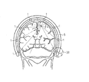
図1は、脳刺激システムの第1実施形態を概略的に示す。ここに示される脳刺激システムは、例として6つの信号発生器1を含む。信号発生器1は、ビーム2の形態で電磁放射を発するように構成される。レンズ系3は、各信号発生器1の集束手段として概略的に示されており、患者の脳5内の共通の標的部位4の上に照射を集中するように、ビーム2の軸に沿って変位可能である。信号発生器1のそれぞれは、患者の脳5内の任意の所望の位置に向けることができるように、別個に調整可能である。信号発生器1がそれに沿って変位可能である枢動軸、長さ方向の変位軸および回転軸は、信号発生器1の1つのみに関して、矢印によって示されている。破線によって示され、参照符号1’で示されるのは、患者の脳5内の異なる部位の上に対応するビーム2’を向けるように変位された信号発生器である。
FIG. 1 schematically illustrates a first embodiment of a brain stimulation system. The brain stimulation system shown here includes six
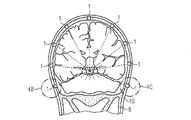
図2は、信号発生器1が共通の支持構造物6の上に取り付けられた、脳刺激システムの第2のより具体的な実施形態を示す。支持構造物6と患者の頭蓋8との間の様々な位置に設けられた詰物7は、患者の頭部の上へ支持構造物6が確実にぴったりと嵌り、快適に収まるようにする。患者の皮膚に疼痛を引き起こすことなく安定した支持を保証するために、詰物は十分に大きく選択される。支持構造物6は、それ自体が弾性であるが、患者の頭蓋8の上の皮膚に対して詰物7を圧迫するように十分に硬い。信号発生器1は、任意の方向に自由に動かせるように支持構造物6の上に取り付けられる。したがって、信号発生器1は、患者の頭蓋に実質的に平行である枢動軸上で枢動するように取り付けられ、枢動軸に対して直角をなす回転軸を中心にさらに回転可能であり、おそらくは、また、回転軸に沿って軸方向に変位可能である。これによって、全ての信号発生器1を、患者の脳5内の共通の標的部位4に向けることができる。
FIG. 2 shows a second more specific embodiment of the brain stimulation system in which the
図3Aは、脳刺激システムの第3実施形態を示し、信号発生器1はやはり共通の支持構造物6上に取り付けられている。しかしながら、この実施形態では、共通の支持構造物6は、ちょうど図2の実施形態において患者の皮膚に対して詰物7を圧迫したように、患者の頭蓋8に対して信号発生器1を圧迫する。図3Bは、信号発生器1をさらに詳細に示す。このように、信号発生器1は取り付け用の管9の中に可動式に取り付けられ、取り付け用の管9は、可撓性であるが硬い支持構造物6によって、患者の頭蓋8に対してぴったりと保持されている。ここに示されるように、取り付け用の管9は、誤って変位するのを防ぐように、患者の皮膚10を貫通し、頭蓋骨に対峙している。患者の皮膚上に取り付け用の管9を取り付けると、患者の皮膚が頭蓋骨上で動くときはいつでも信号発生器1が変位されてしまう。
FIG. 3A shows a third embodiment of the brain stimulation system, in which the
この実施形態で示すように、信号発生器1は、互いに直角をなす2つの枢動軸を中心に枢動可能であり、前記枢動軸の1つのみが矢印によって概略的に示されている。
As shown in this embodiment, the
図4Aは、脳刺激システムの第4および第5の実施形態を(単一の図面で)示す。これらの実施形態では、信号発生器1は患者の頭蓋に恒久的に固定される。信号発生器1の共通の支持構造物は、したがって必要ない。これらの実施形態には、頭蓋8を覆う患者の皮膚10も示されている。上述の他の実施形態には示されていないが、皮膚10は当然ながらやはりそこに存在する。
FIG. 4A shows fourth and fifth embodiments of the brain stimulation system (in a single drawing). In these embodiments, the
図4Aに示される第4実施形態は、図4Bにさらに詳細に示される。このように、信号発生器1はここでも、取り付け用の管9の中に調整可能に包含される。取り付け用の管は、硬膜11を傷つけることなく脳の硬膜11まで頭蓋骨を完全に貫通するように、頭蓋骨構造体8の中へおよび頭蓋骨構造体8を介してそれによってねじ込まれるねじ山12を外側に有する。取り付け用の管9は比較的短く、患者の頭蓋8を貫通しないその残りの部分は患者の皮膚10によって覆われる。無線による遠隔操作および/またはエネルギー伝達が可能でない場合、流電配線が設けられる。このような配線もやはり皮下に配置され、おそらくは患者の首の領域にある制御ユニットに至る。
The fourth embodiment shown in FIG. 4A is shown in more detail in FIG. 4B. Thus, the
図4Aに示される脳刺激システムの第5実施形態が、図4Cにさらに詳細に示される。ここでも、信号発生器1は、取り付け用の管9の中に枢動可能に取り付けられる。しかしながらこの実施形態では、取り付け用の管9は、頭蓋骨の外側の硬い層を完全に貫通することなくその中まで達するのみであり、エネルギーおよび/または制御データを伝導的に与えるためにより容易にアクセス可能となるように、取り付け用の管は患者の皮膚10を介して突出している。
A fifth embodiment of the brain stimulation system shown in FIG. 4A is shown in more detail in FIG. 4C. Again, the
図5は、ここでは図2に関して上述された第2実施形態に関連して示される、個々の信号発生器1にエネルギーおよびデータを与える配線の例を示す。このように、それぞれの信号発生器1は、患者の首の領域に都合よく配置される制御ユニットCに連結される。エネルギー源Eが、また、制御ユニットCおよび信号発生器1にエネルギーを与えるように制御ユニットCに連結される。制御ユニットCおよびエネルギー源Eから離れた処理ユニットPが、制御ユニットCに制御データを、エネルギー源Eにエネルギーを無線で与えるように使用される。制御ユニットCは、フィードバック・データを処理ユニットPに送ることができ、このフィードバック・データは、個々の信号発生器1の位置データなどのシステムの機能的パラメータに関するものである。これに関連して、システムは、個々の信号発生器1の位置を感知する位置センサ(図示せず)をさらに備える。
FIG. 5 shows an example of wiring that provides energy and data to the
患者の身体的なパラメータを感知する身体的パラメータ・センサが制御ユニットに連結され、処理ユニットPに送られるフィードバック・データは、患者のそのような身体的データをさらに含み得る。 A physical parameter sensor for sensing a physical parameter of the patient is coupled to the control unit, and the feedback data sent to the processing unit P may further include such physical data of the patient.
図6から8は、信号発生器の構成の一実施形態を示す。この場合、発生器は複数の異なる方向に一次コイル500を変位させるように構成されたコイル変位ユニットである。しかしながら、信号発生器は任意の種類の発生器であり得る。コイル500は、後述するように、可動式のやり方で懸架される支持シリンダ502に取り付けられる。
6 to 8 show one embodiment of the configuration of the signal generator. In this case, the generator is a coil displacement unit configured to displace the
コイル変位ユニットは、支持シリンダ502に機械的に連結され、それによってまた一次コイル500に機械的に連結される複数の位置調整モータを備える。それぞれの位置調整モータは、図5の外部制御ユニットCに対応する、図6から8に示されないプロセッサに位置情報を与えるように構成される、同様に図示されないいくつかのタイプの位置センサをさらに含む。プロセッサは、受信した制御信号および位置センサからの位置情報に基づいて一次コイル500の動きを制御するように構成される。
The coil displacement unit includes a plurality of position adjustment motors that are mechanically coupled to the
コイル変位ユニットは、一次コイルの自由な動きを可能にするように、位置調整モータおよび一次コイルを支持し囲む、図7および8に示されない筐体504をさらに備える。
The coil displacement unit further comprises a
コイル変位ユニットは、矢印A1によって示される、患者の頭蓋に対して実質的に直角をなす第1方向に一次コイルを変位させる距離調整リニア・モータM1Lをさらに備える。 The coil displacement unit further comprises a distance adjusting linear motor M1L for displacing the primary coil in a first direction indicated by arrow A1 substantially perpendicular to the patient's skull.
コイル変位ユニットは、矢印A2によって示されるように、第1距離調整軸DA1を中心に一次コイルを回転させることによって、前記患者の頭蓋に対して実質的に平行である第2方向に一次コイルを変位させるように構成される第1距離調整回転モータM1Rをさらに備える。 The coil displacement unit turns the primary coil in a second direction substantially parallel to the patient's skull by rotating the primary coil about the first distance adjustment axis DA1, as indicated by arrow A2. A first distance adjusting rotary motor M1R configured to be displaced is further provided.
コイル変位ユニットは、矢印A3によって示されるように、第1距離調整軸DA1に実質的に平行であるが第1距離調整軸DA1から離れた第2距離調整軸DA2を中心に一次コイルを回転させることによって、第2方向に一次コイルを変位させるように構成される第2距離調整回転モータM2Rをさらに備える。 The coil displacement unit rotates the primary coil about the second distance adjustment axis DA2 that is substantially parallel to the first distance adjustment axis DA1 but away from the first distance adjustment axis DA1, as indicated by the arrow A3. Thus, a second distance adjusting rotary motor M2R configured to displace the primary coil in the second direction is further provided.
コイル変位ユニットは、矢印A4によって示されるように、第1角度調整軸AA1を中心に一次コイルを回転させるように構成される第1角度調整リニア・モータM2Lをさらに備える。第1角度調整軸は、患者の頭蓋に実質的に平行であり、モータM2Lは、患者の頭蓋に対して実質的に直角をなす第1平面において一次コイルを回転させるように構成される。 The coil displacement unit further includes a first angle adjustment linear motor M2L configured to rotate the primary coil about the first angle adjustment axis AA1, as indicated by arrow A4. The first angle adjustment axis is substantially parallel to the patient's skull and the motor M2L is configured to rotate the primary coil in a first plane that is substantially perpendicular to the patient's skull.
コイル変位ユニットは、第1角度調整軸AA3に対して直角をなす第2角度調整軸AA2を中心に一次コイルを回転させるように構成される第2角度調整リニア・モータM3Lをさらに備える。第2角度調整軸AA2は、患者の頭蓋に実質的に平行であり、モータM3Lは、患者の頭蓋に対して実質的に直角をなし、第1平面に対して実質的に直角をなす第2平面において一次コイルを回転するように構成される。 The coil displacement unit further includes a second angle adjustment linear motor M3L configured to rotate the primary coil around a second angle adjustment axis AA2 that is perpendicular to the first angle adjustment axis AA3. The second angle adjustment axis AA2 is substantially parallel to the patient's skull, and the motor M3L is substantially perpendicular to the patient's skull and second substantially perpendicular to the first plane. The primary coil is configured to rotate in a plane.
一次コイル500が回転儀のように任意の方向に傾けられ得るように、コイル変位ユニットは、第2角度調整軸AA2と同軸である向かい合う第1回転軸受B1によって一次コイルが内側に取り付けられる第1リング部材R1と、第1角度調整軸AA1と同軸である向かい合う第2回転軸受B2によって第1リング部材R1が内側に取り付けられる第2リング部材R2とをさらに備える。
In order to allow the
発明の好ましい実施例は下記のとおり定義する。
システム:標的部位に累積された刺激
(付記1)
少なくとも2つ、好ましくは3つ以上の刺激信号発生器であって、患者の脳の神経細胞に無線刺激を組み合わせで与える刺激信号を生成するよう構成された刺激信号発生器を備え、
それらの刺激信号発生器は、異なる位置から患者の脳内の共通の標的部位に向けられた刺激信号が生成されて、累積された刺激効果が当該標的部位に与えられるように構成され、
それらの刺激信号発生器は、当該標的部位において累積された刺激信号が脳神経細胞の解剖学的構造体に悪影響を及ぼさないように調整可能である、ことを特徴とする治療的脳刺激システム。
(付記2)
刺激信号は、神経脳細胞またはその近傍に電流を誘導するのに適している、付記1に記載のシステム。
(付記3)
刺激信号は、神経脳細胞に化学反応を刺激するのに適している、付記1または2に記載のシステム。
Preferred embodiments of the invention are defined as follows.
System: Stimulation accumulated at target site (Appendix 1)
At least two, preferably three or more stimulation signal generators, comprising a stimulation signal generator configured to generate a stimulation signal that provides a combination of wireless stimulation to nerve cells of a patient's brain;
The stimulation signal generators are configured such that stimulation signals directed to a common target site in the patient's brain are generated from different locations and the accumulated stimulation effect is applied to the target site,
The therapeutic brain stimulation system, wherein the stimulation signal generators are adjustable so that the stimulation signals accumulated at the target site do not adversely affect the anatomy of the brain neurons.
(Appendix 2)
The system of
(Appendix 3)
The system according to
電磁放射
(付記4)
信号発生器は、電磁放射の形で個々の刺激信号を放射するのに適している、付記1〜3のいずれかに記載のシステム。
(付記5)
電磁放射は、赤外線から紫外線までの間の波長を有する光波を含む、付記4に記載のシステム。
(付記6)
電磁放射は、赤外光より長い波長を有する、付記4に記載のシステム。
(付記7)
電磁放射は、マイクロ波を含む、付記4に記載のシステム。
(付記8)
信号発生器それぞれから放射される刺激信号は、標的部位において相互に交差するか交差可能なビームの形で放射される、付記1〜7のいずれかに記載のシステム。
(付記9)
ビームを標的部位に集中させるための焦点調整装置を含む、付記8に記載のシステム。
Electromagnetic radiation (Appendix 4)
4. A system according to any of
(Appendix 5)
The system of claim 4, wherein the electromagnetic radiation comprises a light wave having a wavelength between infrared and ultraviolet.
(Appendix 6)
The system of claim 4, wherein the electromagnetic radiation has a longer wavelength than infrared light.
(Appendix 7)
The system of claim 4, wherein the electromagnetic radiation comprises microwaves.
(Appendix 8)
8. A system according to any of
(Appendix 9)
The system of
音波
(付記10)
信号発生器は、個々の刺激信号を音波の形で発するのに適している、付記1〜3のいずれかに記載のシステム。
(付記11)
音波は超音波である、付記10に記載のシステム。
(付記12)
信号発生器は、標的部位からの等距離に配設され又は配置可能である、付記10または11に記載のシステム。
(付記13)
信号発生器は、標的部位から正しい位相距離に配設され又は配置可能である、付記10または11に記載のシステム。
Sound wave (Appendix 10)
The system according to any one of
(Appendix 11)
The system according to
(Appendix 12)
12. A system according to
(Appendix 13)
12. System according to
電磁場の誘導電流
(付記14)
信号発生器は、個々の刺激信号を電磁場の形で発するのに適している、付記1〜3のいずれかに記載のシステム。
(付記15)
信号発生器は、それぞれからの電磁場が共直線に誘導される電流方向に相互に重畳するように、調整され又は調整可能である、付記14に記載のシステム。
Induction current of electromagnetic field (Appendix 14)
The system according to any one of appendices 1-3, wherein the signal generator is suitable for emitting individual stimulation signals in the form of an electromagnetic field.
(Appendix 15)
15. The system of claim 14, wherein the signal generators are tuned or tunable so that the electromagnetic fields from each overlap each other in the direction of current induced in a collinear fashion.
信号発生器の構造
(付記16)
信号発生器は、標的部位を通る対称軸を中心とするヘリカル巻線を含む、付記1〜15のいずれかに記載のシステム。
Structure of signal generator (Appendix 16)
16. A system according to any of clauses 1-15, wherein the signal generator includes a helical winding about an axis of symmetry passing through the target site.
永久的に頭に取付けられた発生器
(付記17)
信号発生器は、患者の頭蓋に直接または間接に永久的に取り付けるよう構成されている、付記1から16のいずれかに記載のシステム。
(付記18)
信号発生器は、頭蓋骨構造への取り付けに適している、付記17に記載のシステム。
(付記19)
信号発生器は、頭蓋骨構造にその固い外層のみ透過して取り付けるのに適している、付記18に記載のシステム。
(付記20)
信号発生器は、頭蓋骨構造にそれを完全に透過して取り付けるのに適している、付記18に記載のシステム。
(付記21)
信号発生器は、頭蓋骨構造への固定のための一つ以上のねじを含む、付記18〜20に記載のシステム。
(付記22)
信号発生器の各々は、ねじを外面に備える取付管に含まれている、付記21に記載のシステム。
(付記23)
信号発生器は、移植後に皮膚を透過しないように皮下に移植されるのに適している、付記18〜22のいずれかに記載のシステム。
(付記24)
複数の信号発生器は、患者の頭蓋骨に隣接して配置されて共通支持構造体に結合され、その共通支持構造体は、信号発生器を患者頭蓋骨に接触させて保持するのに充分な剛性を有している、付記17に記載のシステム。
Generator permanently attached to the head (Appendix 17)
17. A system according to any of
(Appendix 18)
The system of claim 17, wherein the signal generator is suitable for attachment to a skull structure.
(Appendix 19)
The system of claim 18, wherein the signal generator is suitable for permeating and attaching only its hard outer layer to the skull structure.
(Appendix 20)
The system of claim 18, wherein the signal generator is suitable for mounting it completely through the skull structure.
(Appendix 21)
21. The system of clauses 18-20, wherein the signal generator includes one or more screws for fixation to the skull structure.
(Appendix 22)
The system of claim 21, wherein each of the signal generators is included in a mounting tube having a screw on its outer surface.
(Appendix 23)
23. The system according to any one of appendices 18-22, wherein the signal generator is suitable for being implanted subcutaneously so as not to penetrate the skin after implantation.
(Appendix 24)
The plurality of signal generators are positioned adjacent to the patient's skull and coupled to a common support structure that is sufficiently rigid to hold the signal generator in contact with the patient's skull. 18. The system according to appendix 17, having.
支持構造体に取付けられた発生器
(付記25)
信号発生器は、患者の頭蓋に載置される共通支持構造体の上に配設され、それぞれの刺激信号を、前記支持構造体の異なる位置から患者の脳における共通した標的部位へと放射し、当該標的部位での累積刺激の効果を与えるようになし得る、付記1〜16のいずれかに記載のシステム。
(付記26)
支持構造体は、患者の頭蓋に着脱可能に、載置するのに適している、付記25に記載のシステム。
(付記27)
支持構造体および患者の頭蓋の間に位置されるべき詰め物が、支持構造体に設けられている、付記26に記載のシステム。
(付記28)
支持構造体は、ヘルメットのような帽子に組み込まれる、付記25〜27のいずれかに記載のシステム。
(付記29)
支持構造体は、頭蓋骨構造への固定に適した脚部を含む、付記25に記載のシステム。
(付記30)
支持構造体は、患者の頭蓋骨に隣接して配置される脚部を有し、その共通支持構造体は、脚部を患者頭蓋骨に接触させて保持するのに充分な剛性を有している、付記25〜28のいずれかに記載のシステム。
(付記31)
個々の刺激信号が標的部位に累積されるように、支持構造体における信号発生器の相対位置を調整する調整デバイスを更に含む、付記25〜30のいずれかに記載のシステム。
(付記32)
信号発生器は、少なくとも一つの枢軸のまわりで回動可能に支持構造体に配設されている、付記31に記載のシステム。
(付記33)
支持構造体は、信号発生器が移動可能である曲り梁を含む、付記25〜32のいずれかに記載のシステム。
(付記34)
曲り梁は、180°の曲率のを受け入れる付記33に記載のシステム。
(付記35)
信号発生器は、標的部位に接近または離間する向きにおいて移動可能に、支持構造体に配設される、付記25〜34のいずれかに記載のシステム。
Generator attached to support structure (Appendix 25)
The signal generator is disposed on a common support structure that rests on the patient's skull and emits respective stimulation signals from different locations of the support structure to a common target site in the patient's brain. The system according to any one of
(Appendix 26)
26. The system of claim 25, wherein the support structure is suitable for placement on a patient's skull in a removable manner.
(Appendix 27)
27. The system of claim 26, wherein the padding to be positioned between the support structure and the patient's skull is provided on the support structure.
(Appendix 28)
28. A system according to any of clauses 25 to 27, wherein the support structure is incorporated into a hat such as a helmet.
(Appendix 29)
26. The system of claim 25, wherein the support structure includes a leg suitable for fixation to the skull structure.
(Appendix 30)
The support structure has a leg disposed adjacent to the patient's skull, and the common support structure has sufficient rigidity to hold the leg in contact with the patient's skull. The system according to any one of appendices 25 to 28.
(Appendix 31)
31. The system of any of clauses 25-30, further comprising an adjustment device that adjusts the relative position of the signal generator in the support structure such that individual stimulation signals are accumulated at the target site.
(Appendix 32)
32. The system of clause 31, wherein the signal generator is disposed on the support structure so as to be rotatable about at least one pivot.
(Appendix 33)
33. A system according to any of clauses 25-32, wherein the support structure includes a curved beam to which the signal generator is movable.
(Appendix 34)
34. The system of claim 33, wherein the curved beam accepts a 180 ° curvature.
(Appendix 35)
35. A system according to any of clauses 25-34, wherein the signal generator is disposed on the support structure such that the signal generator is movable in a direction toward or away from the target site.
モーター
(付記36)
調整デバイスは、支持構造体上の信号発生器を移動させる、少なくとも一つのモーターを含む、付記35〜35のいずれかに記載のシステム。
(付記37)
信号発生器ごとに少なくとも一つの位置調節モーターを、刺激すべき標的に関する信号発生器の調整のために含む、付記1〜36のいずれかに記載のシステム。
(付記38)
前記の少なくとも一つの位置調節モーターには、信号発生器および標的部位の間の距離の調整に適する、少なくとも一つの距離調整モーターが含まれる、付記37に記載のシステム。
(付記39)
前記の少なくとも一つの距離調整モーターは、患者の頭蓋に実質的に垂直方向において信号発生器を移動させるのに適した、距離調整リニアモータを含む、付記38に記載のシステム。
(付記40)
前記の少なくとも一つの距離調整モーターは、少なくとも第1の距離調整回転モーターを含み、当該第1の距離調整回転モーターが、第1の距離調節軸の回りで信号発生器を回すことによって患者の頭蓋と実質的に平行な方向において信号発生器を移動させるのに適している、付記38〜39のいずれかに記載のシステム。
(付記41)
前記の少なくとも一つの距離調整モーターは、少なくとも第2の距離調整回転モーターを含み、当該第2の距離調整回転モーターが、第1の距離調節軸から離間し且つそれに平行な第2の距離調節軸の回りで信号発生器を回すことによって患者の頭蓋と実質的に平行な方向において信号発生器を移動させるのに適している、付記40のいずれかに記載のシステム。
(付記42)
前記の少なくとも一つの距離調整モーターは、前記標的部位に対する信号発生器の角度を調整するのに適している、少なくとも一つの角度調整モーターを含む、付記37〜41のいずれかに記載のシステム。
(付記43)
前記の少なくとも一つの角度調整モーターは、第1の角度調節軸の回りで信号発生器を回すのに適した第1角度調整モーターを含む、付記42に記載のシステム。
(付記44)
第1の角度調節軸は、患者の頭蓋と実質的に平行であり、第1角度調整モーターは、第1平面の信号発生器を患者の頭蓋に対して実質的に垂直にするのに適している。
(付記45)
前記第1角度調整モーターは、リニアモータである、付記44に記載のシステム。
(付記46)
前記第1角度整モーターは、回転モーターである、付記44に記載のシステム。
(付記47)
前記少なくとも一つの角度調整モーターは、第2の角度調節軸のまわりで信号発生器を前記第1の角度調節軸と直角をなすようにするのに適している第2角度調整モーターを含む、付記43から46のいずれかに記載のシステム。
(付記48)
前記第2の角度調節軸は、患者の頭蓋と実質的に平行であり、前記第2角度調整モーターは、前記第1の平面と実質的に直角をなす第2の平面において信号発生器を患者の頭蓋に対して実質的に垂直にするのに適していて、付記47に記載のシステム。
(付記49)
前記第2角度調整モーターは、リニアモータである、付記48に記載のシステム。
(付記50)
前記第2角度整モーターは、回転モーターである、付記48のシステム。
(付記51)
前記位置調整装置デバイスは、前記第2の角度調節軸に同軸で対向する第1の回転ベアリングによって信号発振器を内部に取り付けた第1のリング部材と、
前記第1の角度調節軸に同軸で対向する第2の回転ベアリングによって前記第1のリング部材を内部に取り付けた第2のリング部材とを含み、当該信号発生記を、何れの方向にもジャイロのように傾けることができる、ことを特徴とする、付記47〜50のいずれかに記載のシステム。
Motor (Appendix 36)
36. A system according to any of clauses 35-35, wherein the conditioning device includes at least one motor that moves the signal generator on the support structure.
(Appendix 37)
37. A system according to any of clauses 1-36, comprising at least one position adjustment motor for each signal generator for adjustment of the signal generator with respect to the target to be stimulated.
(Appendix 38)
38. The system of clause 37, wherein the at least one position adjustment motor includes at least one distance adjustment motor suitable for adjusting a distance between the signal generator and the target site.
(Appendix 39)
39. The system of clause 38, wherein the at least one distance adjustment motor comprises a distance adjustment linear motor suitable for moving the signal generator in a direction substantially perpendicular to the patient's cranium.
(Appendix 40)
The at least one distance adjustment motor includes at least a first distance adjustment rotation motor, the first distance adjustment rotation motor turning a signal generator about a first distance adjustment axis to cause the patient's skull. 40. The system of any of clauses 38-39, wherein the system is suitable for moving the signal generator in a direction substantially parallel to.
(Appendix 41)
The at least one distance adjustment motor includes at least a second distance adjustment rotation motor, and the second distance adjustment rotation motor is spaced apart from and parallel to the first distance adjustment axis. 41. The system according to any of clause 40, wherein the system is suitable for moving the signal generator in a direction substantially parallel to the patient's cranium by turning the signal generator about.
(Appendix 42)
42. A system according to any of clauses 37-41, wherein the at least one distance adjustment motor includes at least one angle adjustment motor suitable for adjusting the angle of the signal generator relative to the target site.
(Appendix 43)
43. The system of clause 42, wherein the at least one angle adjustment motor includes a first angle adjustment motor suitable for turning a signal generator about a first angle adjustment axis.
(Appendix 44)
The first angle adjustment axis is substantially parallel to the patient's cranium, and the first angle adjustment motor is suitable for making the first plane signal generator substantially perpendicular to the patient's cranium. Yes.
(Appendix 45)
45. The system according to appendix 44, wherein the first angle adjustment motor is a linear motor.
(Appendix 46)
45. The system of claim 44, wherein the first angle adjustment motor is a rotary motor.
(Appendix 47)
The at least one angle adjustment motor includes a second angle adjustment motor suitable for causing a signal generator to be perpendicular to the first angle adjustment axis about a second angle adjustment axis. 47. The system according to any one of 43 to 46.
(Appendix 48)
The second angle adjustment axis is substantially parallel to the patient's cranium, and the second angle adjustment motor causes the signal generator to move the patient generator in a second plane substantially perpendicular to the first plane. 48. The system according to appendix 47, wherein the system is suitable for being substantially perpendicular to the skull.
(Appendix 49)
49. The system according to appendix 48, wherein the second angle adjustment motor is a linear motor.
(Appendix 50)
49. The system of appendix 48, wherein the second angle adjustment motor is a rotary motor.
(Appendix 51)
The position adjusting device device includes a first ring member having a signal oscillator mounted therein by a first rotary bearing coaxially opposed to the second angle adjusting axis;
A second ring member having the first ring member mounted therein by a second rotary bearing that is coaxially opposed to the first angle adjustment shaft, and the signal generator is gyroscopic in any direction. The system according to any one of appendices 47 to 50, wherein the system can be tilted as follows.
位置検出器
(付記52)
前記少なくとも一つの位置調節モーターのそれぞれは、位置情報を制御装置に提供する位置検出器を含む、付記37〜51のいずれかに記載のシステム。
(付記53)
システムの一つ以上の要素を直接または間接的に制御する制御装置を含む、付記1〜52のいずれかに記載のシステム。
Position detector (Appendix 52)
52. A system according to any of clauses 37-51, wherein each of the at least one position adjustment motor includes a position detector that provides position information to the controller.
(Appendix 53)
53. A system according to any one of
位置制御装置
(付記54)
制御装置は、刺激される標的部位に対しての信号発生器の位置の調整を制御する位置制御装置を含む、付記53に記載のシステム。
(付記55)
位置制御装置および三次元脳結像システムに結合されたデータ処理システムを含む、付記54に記載のシステム。
Position control device (Appendix 54)
54. The system of clause 53, wherein the controller includes a position controller that controls adjustment of the position of the signal generator relative to the target site to be stimulated.
(Appendix 55)
55. The system of clause 54, comprising a data processing system coupled to the position controller and the three-dimensional brain imaging system.
信号発生制御装置
(付記56)
制御装置は、信号発生器によって発される刺激的な信号の生成を制御するための信号発生制御装置を含む、付記1〜55のいずれかに記載のシステム。
(付記57)
信号発生制御装置は、タイミング、シーケンス、輝度、周波数、期間と言う発生される刺激信号のパラメータのうちの一つ以上のパラメータを制御するのに適している、付記56に記載のシステム。
(付記58)
信号発生制御装置は、刺激的信号の強度を時間とともに変化させるのに適している、付記56または57に記載のシステム。
(付記59)
信号発生制御装置は、刺激信号の強度を周期的に変化させる、付記58に記載のシステム。
(付記60)
患者の物理パラメータを検出するための物理パラメータ・センサを含み、前記信号発生制御装置は、物理パラメータ・センサのセンサ信号に応答して刺激信号の調整を制御するのに適している、付記56〜59のいずれかに記載のシステム。
(付記61)
システムの関数パラメタを検出するための関数パラメタ・センサを含み、
前記信号発生制御装置は、関数パラメタ・センサのセンサ信号に応答して刺激信号の調整を制御する、付記56〜60のいずれかに記載のシステム。
(付記62)
信号発生制御装置は、患者によって操作可能である、付記56から61のいずれかに記載のシステム。
(付記63)
信号発生制御装置は、システムをオン/オフするための手動で操作可能なスイッチを含み、当該スイッチが患者の体外から手動で操作可能であるように皮下埋め込み術に適応している、付記62に記載のシステム。
(付記64)
信号発生制御装置は、システムをオン/オフするのに適している無線式遠隔操作器を含む、付記62に記載のシステム。
(付記65)
信号発生制御装置は、異なる標的部位への刺激を同時に制御するのに適している、付記56〜64のいずれかに記載のシステム。
(付記66)
信号発生制御装置は、異なる標的部位への順次刺激を制御するのに適している、付記65に記載のシステム。
(付記67)
信号発生制御装置は、標的部位のうちの1つから他のものへと、刺激を時間とともに移す、付記65に記載のシステム。
(付記68)
信号発生制御装置は、パルス信号の形で刺激信号の放射を制御するのに適している、付記56〜67のいずれかに記載のシステム。
Signal generation control device (Appendix 56)
56. A system according to any of
(Appendix 57)
57. The system of clause 56, wherein the signal generation control device is suitable for controlling one or more parameters of the generated stimulus signal parameters: timing, sequence, brightness, frequency, duration.
(Appendix 58)
58. The system of clause 56 or 57, wherein the signal generation control device is suitable for changing the intensity of the stimulating signal over time.
(Appendix 59)
59. The system according to appendix 58, wherein the signal generation control device periodically changes the intensity of the stimulus signal.
(Appendix 60)
Appendix 56- including a physical parameter sensor for detecting a physical parameter of the patient, wherein the signal generation control device is suitable for controlling adjustment of the stimulation signal in response to the sensor signal of the physical parameter sensor 59. The system according to any one of 59.
(Appendix 61)
Includes a function parameter sensor for detecting system function parameters,
The system according to any one of appendices 56 to 60, wherein the signal generation control device controls adjustment of a stimulation signal in response to a sensor signal of a function parameter sensor.
(Appendix 62)
The system according to any one of appendices 56 to 61, wherein the signal generation control device is operable by a patient.
(Appendix 63)
Appendix 62. The signal generation controller includes a manually operable switch for turning the system on and off and is adapted for subcutaneous implantation such that the switch can be manually operated from outside the patient's body. The system described.
(Appendix 64)
64. The system of clause 62, wherein the signal generation controller includes a wireless remote controller suitable for turning the system on and off.
(Appendix 65)
The system according to any one of appendices 56 to 64, wherein the signal generation control device is suitable for simultaneously controlling stimulation to different target sites.
(Appendix 66)
66. The system of clause 65, wherein the signal generation controller is suitable for controlling sequential stimulation to different target sites.
(Appendix 67)
66. The system of clause 65, wherein the signal generation control device transfers the stimulus over time from one of the target sites to the other.
(Appendix 68)
68. A system according to any of clauses 56 to 67, wherein the signal generation control device is suitable for controlling the emission of the stimulation signal in the form of a pulse signal.
パルス列
(付記69)
信号発生制御装置は、パルス列の形でパルス信号の放出を制御するのに適している、付記68に記載のシステム。
(付記70)
信号発生制御装置は、少なくとも標的部位の第1領域および第2領域が、第1のパルス列および第2のパルス列によって繰り返し刺激されるように、パルス列の放出を制御し、第1のパルス列および第2のパルス列は、時間とともに相互にシフトする、付記65に従属する場合の付記69に記載のシステム。
(付記71)
前記第1の領域が前記第1のパルス列によって刺激され、一方、前記第2領域が前記第2のパルス列によって刺激されないように、または、その逆に、信号発生制御装置はパルス列のシフトされた放出を制御する、付記70に記載のシステム。
(付記72)
前記第1および第2のパルス列が少なくとも部分的に重なり合うように、信号発生制御装置はパルス列のシフトされた放出を制御する、付記70に記載のシステム。
(付記73)
信号発生制御装置は、パルス列のパルスの振幅を変化させて刺激的信号の放射を制御する、付記69〜72のいずれかに記載のシステム。
(付記74)
信号発生制御装置は、パルス列のパルス間におけるオフタイム期間を変化させて刺激信号の放射を制御する、付記69〜73のいずれかに記載のシステム。
(付記75)
前記信号発生制御装置は、前記パルス列の周波数を変化させて刺激的信号の放射を制御する、付記69〜74のいずれかに記載のシステム。
(付記76)
信号発生制御装置は、パルス列中のパルス周波数を変化させて刺激信号の放射を制御する、付記69〜75のいずれかに記載のシステム。
(付記77)
信号発生制御装置は、パルス列のパルスの幅を変化させて刺激信号の放射を制御する、付記69〜76のいずれかに記載のシステム。
(付記78)
信号発生制御装置は、パルス列間におけるオフタイム期間を変化させて刺激信号の放射を制御する、付記69〜77のいずれかに記載のシステム。
(付記79)
特定の標的部位域がオフタイム期間間に刺激されないときに、信号発生制御装置は標的部位の良好な刺激環境を復元するのに十分長いパルス列間のオフタイムでパルス列の放出を制御する、付記78に記載のシステム。
(付記80)
信号発生制御装置は、パルス列長さを変化させてパルス列の放出を制御する、付記69〜79のいずれかに記載のシステム。
(付記81)
信号発生制御装置は、パルス列のパルス数を変化させて刺激信号の放射を制御する、付記69〜80のいずれかに記載のシステム。
Pulse train (Appendix 69)
69. The system of clause 68, wherein the signal generation controller is suitable for controlling the emission of the pulse signal in the form of a pulse train.
(Appendix 70)
The signal generation control device controls the emission of the pulse train so that at least the first region and the second region of the target site are repeatedly stimulated by the first pulse train and the second pulse train, and the first pulse train and the second pulse train 70. The system of appendix 69 when subordinate to appendix 65, wherein the pulse trains of are mutually shifted with time.
(Appendix 71)
The signal generation controller may cause a shifted emission of the pulse train such that the first region is stimulated by the first pulse train while the second region is not stimulated by the second pulse train, or vice versa. The system according to appendix 70, wherein the system is controlled.
(Appendix 72)
71. The system of clause 70, wherein the signal generation controller controls the shifted emission of the pulse train such that the first and second pulse trains overlap at least partially.
(Appendix 73)
The system according to any one of appendices 69 to 72, wherein the signal generation control device controls the emission of the stimulating signal by changing the amplitude of the pulse of the pulse train.
(Appendix 74)
74. The system according to any one of appendices 69 to 73, wherein the signal generation control device controls emission of the stimulation signal by changing an off time period between pulses of the pulse train.
(Appendix 75)
75. The system according to any one of appendices 69 to 74, wherein the signal generation control device controls emission of a stimulating signal by changing a frequency of the pulse train.
(Appendix 76)
The system according to any one of appendices 69 to 75, wherein the signal generation control device controls the emission of the stimulation signal by changing a pulse frequency in the pulse train.
(Appendix 77)
77. The system according to any one of appendices 69 to 76, wherein the signal generation control device controls the emission of the stimulation signal by changing a pulse width of the pulse train.
(Appendix 78)
78. The system according to any one of appendices 69 to 77, wherein the signal generation control device controls emission of the stimulation signal by changing an off time period between the pulse trains.
(Appendix 79)
Appendix 78. When a particular target site area is not stimulated during the off-time period, the signal generation control device controls the emission of the pulse train with an off-time between pulse trains long enough to restore a good stimulation environment of the target site The system described in.
(Appendix 80)
The system according to any one of appendices 69 to 79, wherein the signal generation control device controls the emission of the pulse train by changing the pulse train length.
(Appendix 81)
The system according to any one of appendices 69 to 80, wherein the signal generation control device controls the emission of the stimulation signal by changing the number of pulses of the pulse train.
制御装置の操作
(付記82)
制御装置は、患者によって操作可能である、付記53〜81のいずれかに記載のシステム。
(付記83)
制御装置は、信号発生器とともに患者の頭蓋に取り付け得る第1部分と、遠隔コミュニケーション用の第2部分とを含んでいる、付記53〜82のいずれかに記載のシステム。
(付記84)
制御装置の第二部品は、ワイヤレスで制御信号を制御装置の第1部分に発信する、付記83に記載のシステム。
(付記85)
制御装置の第1部分は、制御装置の第2部分を介してプログラム可能である、付記83または84に記載のシステム。
(付記86)
制御装置の第2部分は、フィードバック信号を制御装置の第1部分へと発信する、付記83〜85のいずれかに記載のシステム。
Control device operation (Appendix 82)
The system according to any one of appendices 53 to 81, wherein the control device is operable by the patient.
(Appendix 83)
83. A system according to any of clauses 53-82, wherein the controller includes a first portion that can be attached to the patient's skull along with a signal generator and a second portion for remote communication.
(Appendix 84)
84. The system of clause 83, wherein the second part of the control device wirelessly transmits a control signal to the first part of the control device.
(Appendix 85)
85. A system according to clause 83 or 84, wherein the first part of the controller is programmable via the second part of the controller.
(Appendix 86)
The system according to any one of appendices 83 to 85, wherein the second part of the control device transmits a feedback signal to the first part of the control device.
電流/無線遠隔操作
(付記87)
制御装置および信号発生器の間でのデータ転送のための電流結合を含む、付記53〜86のいずれかに記載のシステム。
(付記88)
制御装置および信号発生器の間でのデータを送信するための電波式遠隔操作を含む、付記53〜86のいずれかに記載のシステム。
直流電流のエネルギー供給
Current / wireless remote control (Appendix 87)
90. A system according to any of clauses 53-86, including current coupling for data transfer between the controller and the signal generator.
(Appendix 88)
90. A system according to any of clauses 53 to 86, including a radio remote control for transmitting data between the control device and the signal generator.
DC current energy supply
電流エネルギー供給
(付記89)
エネルギー供給用に信号発生器に接続した電流結合を含む、付記1〜88のいずれかに記載のシステム。
Current energy supply (Appendix 89)
90. A system according to any of
無線エネルギー供給
(付記90)
信号発生器に接続された、少なくとも一つのエネルギー・トランスを含み、無線エネルギーを電気エネルギーに変え、または、間接的に信号発生器に電気エネルギーを供給するようにした、付記1から88のいずれかに記載のシステム。
(付記91)
少なくとも一つのエネルギー・トランスにエネルギーをワイヤレスで発信するエネルギー送信器を含む、付記90に記載のシステム。
(付記92)
患者の脳に移植するための触媒を含む、付記1〜91のいずれかに記載のシステム。
(付記93)
触媒は金属を含む、付記92に記載のシステム。
Wireless energy supply (Appendix 90)
Any one of
(Appendix 91)
94. The system of clause 90, comprising an energy transmitter that wirelessly transmits energy to at least one energy transformer.
(Appendix 92)
92. A system according to any of
(Appendix 93)
95. The system of clause 92, wherein the catalyst comprises a metal.
システムを取り付ける方法
(付記94)
患者頭部上へ、
−患者の脳に隣接して患者の頭蓋骨構造より上の二箇所の患者の皮膚を切り、
−共に患者の脳の神経細胞の無線刺激を考慮に入れる刺激的な信号を生成するのに適している前記信号発生器において、各々の異なる位置に信号発生器を患者の頭蓋に、直接、または、間接的に、取り付け −それら個々の刺激的な信号が前記異なる位置から患者の一般の標的部位の方へ発されるように、前記信号発生器を調整することはその標的部位に対する累積値を刺激している効果を提供するために脳である。そして、前記累積値が否定的に神経単位の脳細胞の解剖学構造に影響を及ぼさないために調整されている標的部位に対する効果を刺激する、付記17に従属する場合の付記1から93の何れかに記載のシステムを取り付ける方法。
How to install the system (Appendix 94)
Onto the patient's head,
-Cut the patient's skin in two places above the patient's skull structure adjacent to the patient's brain,
The signal generator, which is suitable both for generating a stimulating signal that takes into account wireless stimulation of nerve cells of the patient's brain, in each different position the signal generator directly on the patient's skull, or , Indirectly, mounting—adjusting the signal generator so that these individual stimulating signals are emitted from the different locations towards the patient's general target site will result in a cumulative value for that target site. The brain to provide a stimulating effect. And any one of
頭に永久に取り付ける発生器
(付記95)
信号発生器を患者の頭蓋に取り付けるステップで、永久に信号発生器を患者の頭蓋に取り付けることを含む、付記94に記載の方法。
(付記96)
永久に信号発生器を患者の頭蓋に取り付けるステップは、信号発生器を頭蓋骨構造に取り付けることを含む、付記95に記載の方法。
(付記97)
永久に信号発生器を患者の頭蓋に取り付けるステップは、その固い外層だけを透過するために信号発生器を頭蓋骨構造に取り付ける、付記95に記載の方法。
(付記98)
永久に信号発生器を患者の頭蓋に取り付けるステップは、完全に、脳の硬膜に深く入りこむことのない頭蓋骨構造を透過するために信号発生器を頭蓋骨構造に取り付けることを含む、付記95に記載の方法。
(付記99)
信号発生器は一つ以上のねじを含む、そして、永久に信号発生器を患者の頭蓋に取り付けるステップは頭蓋骨構造の信号発生器をねじることを含む、付記95から98のいずれかに記載の方法。
(付記100)
信号発生器の各々は、取付管の外面に設けられているねじを有する取付管に含まれる、付記99に記載の方法。
(付記101)
信号発生器が皮下に移植されて、皮膚を透過しないように、患者の皮膚を縫合する、付記95から100のいずれかに記載の方法。
(付記102)
永久に信号発生器を患者の頭蓋に取り付けるステップは、頭蓋の異なる位置に支持構造体のための脚を取り付けることによって患者の頭蓋上へ支持構造体を修正する付記95に記載の方法。
(付記103)
支持点を患者の頭蓋に取り付けるステップは、その固い外層だけを透過するために頭蓋骨構造の脚部を修正することを含む、付記102に記載の方法。
(付記104)
発生器が前記信号発生器を保つために充分な剛性を提供している一般の支持構造体に接続していて、前記信号、患者頭部の対向側に位置に配列されるときに、患者の頭蓋骨と接触して、永久に信号発生器を患者の頭蓋に取り付けるステップは、患者頭部の対向側に位置に患者の頭蓋骨に隣接して信号発生器を配置することを含む、付記95に記載の方法。
Generator permanently attached to the head (Appendix 95)
95. The method of clause 94, comprising permanently attaching the signal generator to the patient's skull in the step of attaching the signal generator to the patient's skull.
(Appendix 96)
96. The method of clause 95, wherein permanently attaching the signal generator to the patient's skull includes attaching the signal generator to the skull structure.
(Appendix 97)
96. The method of clause 95, wherein the step of permanently attaching the signal generator to the patient's skull attaches the signal generator to the skull structure to penetrate only its hard outer layer.
(Appendix 98)
95. The step of permanently attaching a signal generator to a patient's skull includes attaching the signal generator to the skull structure to penetrate completely through the skull structure without penetrating deeply into the dura of the brain. the method of.
(Appendix 99)
99. The method of any of clauses 95-98, wherein the signal generator includes one or more screws, and the step of permanently attaching the signal generator to the patient's skull includes twisting the signal generator of the skull structure. .
(Appendix 100)
100. The method of clause 99, wherein each of the signal generators is included in a mounting tube having a screw provided on the outer surface of the mounting tube.
(Appendix 101)
101. The method of any one of clauses 95 to 100, wherein the signal generator is implanted subcutaneously and the patient's skin is sutured so that it does not penetrate the skin.
(Appendix 102)
96. The method of clause 95, wherein the step of permanently attaching the signal generator to the patient's skull modifies the support structure onto the patient's skull by attaching legs for the support structure at different locations on the skull.
(Appendix 103)
103. The method of clause 102, wherein the step of attaching the support point to the patient's skull includes modifying the leg of the skull structure to penetrate only its hard outer layer.
(Appendix 104)
When the generator is connected to a general support structure that provides sufficient rigidity to hold the signal generator and the signal is arranged in a position opposite the patient's head, the patient's 96. The appendix 95, wherein the step of permanently attaching the signal generator to the patient's skull in contact with the skull comprises positioning the signal generator adjacent to the patient's skull in a position opposite the patient's head. the method of.
着脱可能な支持構造体に取り付ける発生器
(付記105)
患者頭部上へ
−着脱可能に、共に患者の脳の神経細胞の無線刺激を考慮に入れる刺激的な信号を生成するのに適している少なくとも2つおよび好ましくは3つ以上の信号発生器を支持している前記支持構造体を患者頭部に取り付け、
−それらの個々の刺激的な信号が支持構造体の異なる位置から患者の一般の標的部位の方へ発されるように、支持構造体上の前記信号発生器を調整することはその標的部位に対する累積値を刺激している効果を提供するために脳であり、前記累積値が否定的に神経単位の脳細胞の解剖学構造に影響を及ぼさないために調整されている標的部位に対する効果を刺激する、付記25に従属する場合の付記1から93のいずれかに記載のシステムを取り付ける方法。
(付記106)
着脱可能であって、支持構造体を患者の頭蓋に取り付けるステップは、頭蓋骨の外側に患者の皮膚に対してパディングを有する支持構造体を取り付けることを含む、付記105に記載の方法。
(付記107)
支持構造体は、ヘルメットのような帽子に組み込まれている、付記106に記載の方法。
Generator attached to a detachable support structure (Appendix 105)
Onto the patient's head-at least two and preferably three or more signal generators that are detachably adapted to generate stimulating signals that together take into account wireless stimulation of nerve cells of the patient's brain Attaching the supporting structure to the patient's head,
Adjusting the signal generator on the support structure so that their individual stimulating signals are emitted from different positions of the support structure towards the patient's general target site; Stimulate effects on target sites that are adjusted to prevent the cumulative value from affecting the neuronal brain cell anatomy, which is the brain to provide a stimulating effect A method of attaching the system according to any one of
(Appendix 106)
106. The method of clause 105, wherein the step of attaching and attaching the support structure to the patient's skull includes attaching a support structure that has padding against the patient's skin outside the skull.
(Appendix 107)
107. The method of appendix 106, wherein the support structure is incorporated into a hat such as a helmet.
脳の触媒
(付記108)
打込みの標的部位において、標的部位の増加した累積値刺激を引き起こす触媒として材料からなる、付記94から107のいずれかに記載の方法。
Brain catalyst (Appendix 108)
108. The method according to any one of appendices 94 to 107, comprising a material as a catalyst that causes increased cumulative value stimulation of the target site at the target site of implantation.
調整の方法
(付記109)
システムが患者頭部に載置後、個々の刺激信号が最大限に患者の標的部位にたまるように、信号発生器のうちの少なくとも1つの位置を、患者の脳に予め定められた標的部位と関連して調整するステップを含む、付記1から93のいずれかに記載の方法。
(付記110)
信号発生器を調整するステップは、少なくとも一つのピボット演算軸について信号発生器を回転させることを含む、付記109に記載の方法。
(付記111)
信号発生器を調整するステップは、支持構造体の曲り梁に沿って信号発生器を移動させることを含む、付記109から110のいずれかに記載の方法。
(付記112)
信号発生器を調整するステップは、標的部位の方へ、または離れて信号発生器を移動することを含む、付記109から11のいずれかに記載の方法。
(付記113)
信号発生器は、患者頭部に載置する一般の支持構造体に配置される、付記109から112のいずれかに記載の方法。
(付記114)
信号発生器は、取付管に取り付けられる、付記109から113のいずれかに記載の方法。
(付記115)
信号発生器の位置を調整するステップの方法は、信号発生器の間の距離を調整するステップと標的部位とを具備している、付記109に記載の方法。
(付記116)
標的部位から距離を調整するステップは、第一の方向に患者の頭蓋に対して実質的に垂直な信号発生器を移動させることを含む、付記115に記載の方法。
(付記117)
標的部位から距離を調整するステップは、患者の頭蓋と実質的に平行して第2の方向の信号発生器を移動させることを含む、付記116に記載の方法。
(付記118)
標的部位から距離を調整するステップは、患者の頭蓋に対して実質的に垂直である第1の距離調節軸線周辺で円周上に第2の方向の信号発生器を移動させることを含む、付記117に記載の方法。
(付記119)
標的部位から距離を調整するステップは、第1の距離調節軸線と実質的に平行であるが、別である第2の距離調節軸線周辺で円周上に第2の方向の信号発生器を移動させることを含む、付記118に記載の方法。
(付記120)
標的部位から距離を調整するステップは、信号発生器および標的部位の間の角度を調整することを含む、付記115から119のいずれかに記載の方法。
(付記121)
信号発生器は対称軸周辺でヘリカル巻きから成り、標的部位から距離を調整するステップは標的部位と関連して前記信号発生器の対称軸を回すことを含む、付記120に記載の方法。
(付記122)
標的部位から距離を調整するステップは、第1の角度調節軸線周辺で信号発生器を回すことを含む、付記121に記載の方法。
(付記123)
前記第1の角度調節軸線は患者の皮膚と実質的に平行であり、方法が第2の角度調節軸線のまわりの信号発生器を第1の角度調節軸線と実質的に直角をなすようにするステップを含む、付記122に記載の方法。
Adjustment method (Appendix 109)
After the system is placed on the patient's head, the position of at least one of the signal generators is determined with a predetermined target site in the patient's brain so that individual stimulation signals accumulate at the patient's target site to the maximum extent. 94. A method according to any one of
(Appendix 110)
110. The method of clause 109, wherein the step of adjusting the signal generator includes rotating the signal generator about at least one pivot axis.
(Appendix 111)
111. A method according to any of clauses 109 to 110, wherein the step of adjusting the signal generator includes moving the signal generator along a curved beam of the support structure.
(Appendix 112)
12. A method according to any of clauses 109 to 11, wherein the step of adjusting the signal generator includes moving the signal generator toward or away from the target site.
(Appendix 113)
113. A method according to any of clauses 109 to 112, wherein the signal generator is disposed on a general support structure that rests on the patient's head.
(Appendix 114)
114. A method according to any one of clauses 109 to 113, wherein the signal generator is attached to a mounting tube.
(Appendix 115)
110. The method of clause 109, wherein the method of adjusting the position of the signal generator comprises adjusting the distance between the signal generators and the target site.
(Appendix 116)
116. The method of clause 115, wherein adjusting the distance from the target site includes moving a signal generator substantially perpendicular to the patient's skull in a first direction.
(Appendix 117)
116. The method of clause 116, wherein the step of adjusting the distance from the target site includes moving the signal generator in a second direction substantially parallel to the patient's cranium.
(Appendix 118)
The step of adjusting the distance from the target site includes moving the signal generator in the second direction on a circumference about a first distance adjustment axis that is substantially perpendicular to the patient's skull. 117. The method according to 117.
(Appendix 119)
The step of adjusting the distance from the target site is moving the signal generator in the second direction on the circumference around the second distance adjustment axis, which is substantially parallel to the first distance adjustment axis. 119. The method according to appendix 118, comprising:
(Appendix 120)
120. The method of any of clauses 115 to 119, wherein the step of adjusting the distance from the target site includes adjusting an angle between the signal generator and the target site.
(Appendix 121)
123. The method of clause 120, wherein the signal generator comprises a helical wrap around an axis of symmetry, and the step of adjusting the distance from the target site includes turning the axis of symmetry of the signal generator relative to the target site.
(Appendix 122)
122. The method of clause 121, wherein the step of adjusting the distance from the target site includes turning a signal generator about the first angle adjustment axis.
(Supplementary Note 123)
The first angle adjustment axis is substantially parallel to the patient's skin and the method causes the signal generator about the second angle adjustment axis to be substantially perpendicular to the first angle adjustment axis. 122. The method of appendix 122, comprising steps.
モーター
(付記124)
モーターによってどこに進むか調整し、信号発生器を移動させることが設けられている、付記109から123のいずれかに記載の方法。
(付記125)
一つ以上の別々のモーターによってどこに進むか調整し、発生器が各々の信号発生器を移動させることができる、付記124に記載の方法。
(付記126)
一つ以上の別々のモーターによってどこに進むか調整し、発生器が各々の信号発生器を移動させることができる、付記125に記載の方法。
Motor (Appendix 124)
124. A method according to any one of clauses 109 to 123, wherein the method comprises adjusting where the motor travels and moving the signal generator.
(Appendix 125)
129. The method of clause 124, wherein the one or more separate motors adjust where it travels and the generator can move each signal generator.
(Appendix 126)
129. The method of clause 125, wherein one or more separate motors adjust where to go and the generator can move each signal generator.
位置制御装置
(付記127)
標的部位と関連して、自動的に支持構造体上の信号発生器の相対位置が位置制御装置によって刺激されるように調整するステップを含む、付記109から126のいずれかに記載の方法。
(付記128)
自動的に信号発生器の位置を調整するステップは、位置を三次元脳結像システムから得られるデータに関連させることを含む、付記127のいずれかに記載の方法。
Position control device (Appendix 127)
127. A method according to any of clauses 109 to 126, including the step of automatically adjusting the relative position of the signal generator on the support structure to be stimulated by the position control device relative to the target site.
(Appendix 128)
128. A method according to any of clause 127, wherein the step of automatically adjusting the position of the signal generator comprises associating the position with data obtained from a three-dimensional brain imaging system.
使用の方法
信号発生制御装置
(付記129)
システムが患者頭部に載置したあと、信号エミッタによって発される刺激的な信号の生成を制御するステップを含む、付記1から93のいずれかに記載の方法。
(付記130)
発された個々の刺激の以下に記載のパラメータの制御である、タイミング、シーケンス、輝度、周波数、期間 の一つ以上のステップを含み、信号を送る、付記129に記載の方法。
(付記131)
時間とともに刺激的な信号の輝度を変化させる、付記129から130のいずれかに記載の方法。
(付記132)
周期的に刺激的な信号の輝度を変化させる、付記131に記載の方法。
(付記133)
患者の検出された物理パラメータに応答して、刺激的な信号の輝度を調整するステップを含む、付記129から132のいずれかに記載の方法。
(付記134)
システムの検出された関数パラメターに応答して、刺激的な信号の輝度を調整するステップを含む、付記129から133のいずれかに記載の方法。
(付記135)
システムは刺激信号の放射を制御するための信号発生制御装置を含み、患者は前記信号発生制御装置を操作する、付記129から134のいずれかに記載の方法。
(付記136)
信号発生制御装置はシステムをオン/オフするための皮下に作動された配置されたスイッチから成り、患者は手動で患者のボディの外側でからの転換を操作する、付記135に記載の方法。
(付記137)
電波式遠隔操作を介してシステムをオン/オフするステップを含む、付記135に記載の方法。
(付記138)
一度に標的部位の異なる領域を刺激するステップを含む、付記129から137のいずれかに記載の方法。
(付記139)
順次異なる標的部位域を刺激するステップを含む、付記138に記載の方法。
(付記140)
標的部位域のうちの1つから、標的部位域の別のものへ時間とともに刺激を移すステップを含む付記138に記載の方法。
(付記141)
パルス信号の形で刺激的な信号を発するステップを含む、付記129から140のいずれかに記載の方法。
Method of use Signal generation control device (Appendix 129)
94. A method according to any of
(Appendix 130)
129. The method of clause 129, wherein the method sends one or more steps of timing, sequence, brightness, frequency, duration, which is control of the parameters described below for the individual stimuli emitted.
(Appendix 131)
131. The method according to any one of appendices 129 to 130, wherein the luminance of the stimulating signal is changed over time.
(Appendix 132)
134. The method according to appendix 131, wherein the luminance of the periodically stimulating signal is changed.
(Appendix 133)
135. The method of any of clauses 129-132, comprising adjusting the brightness of the stimulating signal in response to the detected physical parameter of the patient.
(Appendix 134)
134. The method of any of clauses 129-133, comprising adjusting the brightness of the stimulating signal in response to the detected function parameter of the system.
(Appendix 135)
135. A method according to any of clauses 129 to 134, wherein the system includes a signal generation controller for controlling the emission of the stimulation signal, and the patient operates the signal generation controller.
(Appendix 136)
139. The method of clause 135, wherein the signal generation control device comprises a subcutaneously activated placed switch for turning the system on and off, and the patient manually operates the conversion from outside the patient's body.
(Appendix 137)
139. The method of clause 135, comprising turning the system on / off via radio remote control.
(Appendix 138)
142. The method of any of clauses 129 to 137, comprising stimulating different regions of the target site at a time.
(Appendix 139)
142. The method of clause 138, comprising the step of sequentially stimulating different target site areas.
(Appendix 140)
139. The method of clause 138, comprising transferring the stimulus over time from one of the target site areas to another of the target site areas.
(Appendix 141)
141. A method according to any of clauses 129-140, comprising the step of emitting a stimulating signal in the form of a pulse signal.
パルス列
(付記142)
パルス列の形でパルス信号を発するステップを含む、付記141に記載の方法。
(付記143)
少なくとも標的部位域の第1の領域および第2領域が第1のパルス列によって繰り返し刺激されるように、パルス列を発するステップおよび第2のパルス列から成り、前記第1および第2のパルス列については、存在は、各々と関連して時間とともに変わる、付記138及び142に記載の方法。
(付記144)
前記第2領域が前記第2のパルス列によって刺激されないと共に前記第1の領域が前記第1のパルス列によって刺激されるように、パルスの放出を移すステップを含むことは訓練を受ける付記143に記載の方法。
(付記145)
前記第1および第2のパルス列が少なくとも部分的に重なり合うように、パルス列の放出を移すステップを含む、付記143に記載の方法。
(付記146)
パルス列のパルスの振幅を変化させるステップを含む、付記142から145のいずれかに記載の方法。
(付記147)
パルス列のパルスとの間にオフタイム期間を変化させるステップを含む、付記142から146のいずれかに記載の方法。
(付記148)
前記パルス列の周波数を変化させるステップを含む、付記142から147のいずれかに記載の方法。
(付記149)
パルス列の中でパルスの周波数を変化させるステップを含む、付記142から148のいずれかに記載の方法。
(付記150)
パルス列のパルスの幅を変化させるステップを含む、付記142から149のいずれかに記載の方法。
(付記151)
パルス列との間にオフタイム期間を変化させるステップを含む、付記142から150のいずれかに記載の方法。
(付記152)
特定の標的部位域がオフタイム期間の間に刺激されないときに、パルスの放出を制御するステップを含むことは標的部位域の良好な刺激気候を復元するのに十分長いパルス列との間に時限を避けるための訓練を受ける、付記151に記載の方法。
(付記153)
各パルス列の長さを変化させるステップを含む、付記142から152のいずれかに記載の方法。
(付記154)
パルス列のパルスの数を変化させるステップを含む、付記142から153のいずれかに記載の方法。
Pulse train (Appendix 142)
142. The method of clause 141, comprising generating a pulse signal in the form of a pulse train.
(Appendix 143)
A step of emitting a pulse train and a second pulse train such that at least the first region and the second region of the target site region are repeatedly stimulated by the first pulse train, the first and second pulse trains being present 142. The method of clauses 138 and 142, wherein the method changes over time in relation to each.
(Appendix 144)
143. Trained appendix 143, comprising translating a pulse emission such that the second region is not stimulated by the second pulse train and the first region is stimulated by the first pulse train Method.
(Appendix 145)
144. The method of clause 143, comprising the step of shifting the emission of the pulse train such that the first and second pulse trains at least partially overlap.
(Appendix 146)
145. A method according to any of clauses 142 to 145, comprising the step of changing the amplitude of the pulses of the pulse train.
(Appendix 147)
147. A method according to any of clauses 142 to 146, comprising the step of changing the off-time period between pulses of the pulse train.
(Appendix 148)
148. The method according to any one of clauses 142 to 147, comprising the step of changing a frequency of the pulse train.
(Appendix 149)
149. A method according to any of clauses 142 to 148, comprising the step of changing the frequency of the pulses in the pulse train.
(Appendix 150)
150. A method according to any of clauses 142 to 149, comprising the step of changing a pulse width of the pulse train.
(Appendix 151)
151. The method according to any one of clauses 142 to 150, comprising the step of changing the off-time period with the pulse train.
(Appendix 152)
Including a step of controlling the emission of a pulse when a particular target site area is not stimulated during an off-time period can be timed with a pulse train long enough to restore a good stimulation climate of the target site area. The method of appendix 151, undergoing training to avoid.
(Appendix 153)
153. A method according to any of clauses 142 to 152, including the step of changing the length of each pulse train.
(Appendix 154)
154. The method according to any of clauses 142 to 153, comprising the step of changing the number of pulses in the pulse train.
無線データ送信
(付記155)
刺激が信号を送る制御のステップは、電波式遠隔操作を必要とする、付記129に記載の方法。
Wireless data transmission (Appendix 155)
129. The method of clause 129, wherein the step of controlling the stimulus to send a signal requires radio remote control.
無線エネルギー供給
(付記156)
無線エネルギーを電気エネルギーに変えて、直接、または、間接的に信号発生器に電気エネルギーを供給するステップを含む、付記129から155のいずれかに記載の方法。
Wireless energy supply (Appendix 156)
156. The method according to any one of clauses 129 to 155, comprising the step of converting wireless energy into electrical energy and supplying electrical energy directly or indirectly to the signal generator.
電磁放射
(付記157)
個々の刺激を発するステップを含み、電磁放射の形で信号を送る、付記129から156のいずれかに記載の方法。
(付記158)
電磁放射は、赤外線および紫外との間に波長を有する光波を範囲に含む、付記157に記載の方法。
(付記159)
電磁放射は、赤外光より長く、波長を有する波を含む、付記157に記載の方法。
(付記160)
電磁放射は、電子レンジを含む、付記159に記載の方法。
(付記161)
信号発生器によって発される、個々の刺激信号は、ビームの形で発され、標的部位の各々を交差させるためにビームを導くステップをさらに含んでいる付記129から160のいずれかに記載の方法。
(付記162)
標的部位にビームを集中させるステップを含む、付記161に記載の方法。
(付記163)
標的部位の交差ビームは、一つ以上の神経細胞の治療的な刺激信号を引き起こす、付記161から162のいずれかに記載の方法。
Electromagnetic radiation (Appendix 157)
155. A method according to any of clauses 129 to 156, comprising emitting individual stimuli and sending a signal in the form of electromagnetic radiation.
(Appendix 158)
158. The method of appendix 157, wherein the electromagnetic radiation includes a light wave having a wavelength between infrared and ultraviolet.
(Appendix 159)
158. The method of clause 157, wherein the electromagnetic radiation comprises a wave having a wavelength longer than infrared light.
(Appendix 160)
159. The method of appendix 159, wherein the electromagnetic radiation includes a microwave oven.
(Appendix 161)
161. A method according to any of clauses 129-160, wherein the individual stimulus signals emitted by the signal generator are emitted in the form of beams and further include directing the beams to intersect each of the target sites. .
(Appendix 162)
163. The method of clause 161, comprising the step of focusing the beam at the target site.
(Supplementary Note 163)
163. The method according to any of clauses 161-162, wherein the crossed beam at the target site causes a therapeutic stimulation signal for one or more neurons.
音波
(付記164)
個々の刺激を発するステップを含み、信号発生器によって音波の形で信号を送る、付記129から156のいずれかに記載の方法。
(付記165)
発される音波が超音波音波を含む、付記164に記載の方法。
(付記166)
標的部位から信号発生器を等しい距離に置くステップを含む、付記164から165のいずれかに記載の方法。
(付記167)
距離が決定される標的部位から少し離れて信号発生器を配置するステップを含む、超音波の位相の依存に関する付記164から166のいずれかに記載の方法。
Sound wave (Appendix 164)
157. A method according to any of clauses 129 to 156, comprising the step of emitting individual stimuli, wherein the signal is sent in the form of sound waves by a signal generator.
(Appendix 165)
165. The method of appendix 164, wherein the emitted sound wave comprises an ultrasonic wave.
(Appendix 166)
166. The method of any of clauses 164 to 165, comprising placing the signal generator at an equal distance from the target site.
(Appendix 167)
173. A method according to any of clauses 164 to 166 regarding the phase dependence of the ultrasound comprising the step of positioning the signal generator at a distance from the target site where the distance is determined.
電磁場−誘導電流
(付記168)
引き起こしている電磁場の形で個々の刺激信号を発するステップから成り、患者の脳の予め定められた標的部位の神経細胞の電流に関する、付記129から156のいずれかに記載の方法。
(付記169)
それぞれの電磁場が、同一直線上にあり、重なり合うように、信号発生器を調整する、標的部位の現在の方向を誘導した、付記168に記載の方法。
Electromagnetic field-induced current (Appendix 168)
157. A method according to any one of clauses 129 to 156, comprising the step of emitting individual stimulation signals in the form of an inducing electromagnetic field and relating to the neuronal current of a predetermined target site of the patient's brain.
(Appendix 169)
169. The method of clause 168, wherein the current direction of the target site is derived by adjusting the signal generator so that each electromagnetic field is collinear and overlapping.
1 刺激信号発生器; 2 ビーム; 4 標的部位; 5 脳。 1 Stimulus signal generator; 2 Beam; 4 Target site; 5 Brain.
Claims (15)
前記刺激信号発生器(1)は、異なる位置から患者の脳内の共通の標的部位(4)に向けられた刺激信号を発し、累積された刺激効果を前記標的部位(4)に与えるように配置され、前記刺激信号発生器(1)は、前記標的部位において前記累積された刺激信号が脳神経細胞の解剖学的構造体に悪影響を及ぼさないように調整可能であり、
前記刺激信号発生器(1)は、頭蓋骨構造(8)の外層のみを透過、あるいは前記頭蓋骨構造(8)に完全に透過するように、永久的に前記頭蓋骨の構造(8)に取り付けられるように構成され、
前記刺激信号発生器(1)の各々は、前記頭蓋骨構造(8)に固定するための1つまたは複数のねじ(12)を有し、前記刺激信号発生器(1)の各々はそれぞれの取付管(9)内に収容され、前記複数のねじ(12)は前記取付管(9)の外面に具備され、
前記刺激信号発生器(1)の向きは、前記患者の頭蓋に直接または間接に永久的に取り付けられた後、前記取付管(9)内で調整可能であることを特徴とすることを特徴とする治療的脳刺激システム。 Comprising at least two stimulation signal generators (1) configured to generate stimulation signals that provide a combination of wireless stimulation to nerve cells of a patient's brain (5);
The stimulation signal generator (1) emits stimulation signals directed from different positions to a common target site (4) in the patient's brain, and provides a cumulative stimulation effect to the target site (4). Disposed and the stimulation signal generator (1) is adjustable such that the accumulated stimulation signal at the target site does not adversely affect the anatomy of the brain neurons,
The stimulus signal generator (1) may be permanently attached to the skull structure (8) so as to penetrate only the outer layer of the skull structure (8) or completely penetrate the skull structure (8). Composed of
Each of the stimulation signal generators (1) has one or more screws (12) for fixation to the skull structure (8), and each of the stimulation signal generators (1) has a respective mounting. Housed in a tube (9), the plurality of screws (12) are provided on the outer surface of the mounting tube (9),
The orientation of the stimulus signal generator (1) is adjustable in the attachment tube (9) after being permanently attached directly or indirectly to the patient's skull. A therapeutic brain stimulation system.
Applications Claiming Priority (2)
| Application Number | Priority Date | Filing Date | Title |
|---|---|---|---|
| US7147108P | 2008-04-30 | 2008-04-30 | |
| US61/071,471 | 2008-04-30 |
Related Parent Applications (1)
| Application Number | Title | Priority Date | Filing Date |
|---|---|---|---|
| JP2011506612A Division JP2011518629A (en) | 2008-04-30 | 2009-04-30 | Brain stimulation |
Related Child Applications (1)
| Application Number | Title | Priority Date | Filing Date |
|---|---|---|---|
| JP2016077947A Division JP2016152941A (en) | 2008-04-30 | 2016-04-08 | Brain stimulation system |
Publications (2)
| Publication Number | Publication Date |
|---|---|
| JP2014184330A true JP2014184330A (en) | 2014-10-02 |
| JP6219786B2 JP6219786B2 (en) | 2017-10-25 |
Family
ID=41202431
Family Applications (3)
| Application Number | Title | Priority Date | Filing Date |
|---|---|---|---|
| JP2011506612A Pending JP2011518629A (en) | 2008-04-30 | 2009-04-30 | Brain stimulation |
| JP2014130013A Active JP6219786B2 (en) | 2008-04-30 | 2014-06-25 | Brain stimulation system |
| JP2016077947A Pending JP2016152941A (en) | 2008-04-30 | 2016-04-08 | Brain stimulation system |
Family Applications Before (1)
| Application Number | Title | Priority Date | Filing Date |
|---|---|---|---|
| JP2011506612A Pending JP2011518629A (en) | 2008-04-30 | 2009-04-30 | Brain stimulation |
Family Applications After (1)
| Application Number | Title | Priority Date | Filing Date |
|---|---|---|---|
| JP2016077947A Pending JP2016152941A (en) | 2008-04-30 | 2016-04-08 | Brain stimulation system |
Country Status (7)
| Country | Link |
|---|---|
| US (1) | US8644940B2 (en) |
| EP (2) | EP2288409B1 (en) |
| JP (3) | JP2011518629A (en) |
| AU (1) | AU2009242385B2 (en) |
| CA (2) | CA3126522A1 (en) |
| ES (1) | ES2708474T3 (en) |
| WO (1) | WO2009132855A2 (en) |
Families Citing this family (28)
| Publication number | Priority date | Publication date | Assignee | Title |
|---|---|---|---|---|
| CN102802725B (en) * | 2009-06-17 | 2015-12-09 | 内克斯蒂姆股份公司 | Magnetic stimulation device and method |
| WO2011101039A1 (en) | 2010-02-22 | 2011-08-25 | Universite Pierre Et Marie Curie (Paris 6) | Apparatus for the treatment of brain affections and method implementing thereof |
| ITPR20100043A1 (en) * | 2010-05-03 | 2011-11-04 | F & B Internat S R L | MEDICAL DEVICE FOR MAGNETOTHERAPY. |
| ES2584388T3 (en) | 2011-07-27 | 2016-09-27 | Université Pierre Et Marie Curie (Paris 6) | Device for the treatment of a person's sensory capacity |
| EP3119473A1 (en) * | 2014-03-17 | 2017-01-25 | The United States of America, as represented by The Secretary, Department of Health and Human Services | System with an electromagnetic field generator with coils for treating tumors and a method for treating tissue |
| WO2015153746A1 (en) * | 2014-04-04 | 2015-10-08 | University Of Iowa Research Foundation | Close-proximity range shifting device for proton radiosurgery |
| FR3024355A1 (en) | 2014-07-30 | 2016-02-05 | Jean Tien | EQUIPMENT FOR THE APPLICATION OF ACTIVE ELEMENTS ON THE SKULL OF A PATIENT |
| CN111701155A (en) | 2014-12-19 | 2020-09-25 | 索邦大学 | Implantable ultrasound generating therapy device for brain therapy, apparatus comprising such a device and method of implementing such a device |
| EP3242712B1 (en) | 2015-01-09 | 2019-04-10 | Axonics Modulation Technologies, Inc. | Patient remote and associated methods of use with a nerve stimulation system |
| EP3426347A1 (en) | 2016-03-11 | 2019-01-16 | Sorbonne Universite | Implantable ultrasound generating treating device for spinal cord and/or spinal nerve treatment, apparatus comprising such device and method |
| JP6772288B2 (en) | 2016-03-11 | 2020-10-21 | ソルボンヌ・ユニヴェルシテSorbonne Universite | An extracorporeal ultrasound generation therapy device for the treatment of the spinal cord and spinal nerves, a device equipped with the device, and a method using the device. |
| US10589096B2 (en) | 2016-04-25 | 2020-03-17 | The Board Of Regents Of The University Of Texas System | Systems and methods for network based neurostimulation of cognitive processes |
| KR101861963B1 (en) * | 2017-06-30 | 2018-05-28 | 한국과학기술원 | Method for stimulating, and apparatuses performing the same |
| US11712579B2 (en) * | 2017-07-21 | 2023-08-01 | Varian Medical Systems, Inc. | Range compensators for radiation therapy |
| US11590364B2 (en) * | 2017-07-21 | 2023-02-28 | Varian Medical Systems International Ag | Material inserts for radiation therapy |
| KR101953615B1 (en) * | 2017-10-16 | 2019-03-04 | 서울대학교산학협력단 | Applicator using metal plate and short stub for brain stimulation |
| JP7071728B2 (en) * | 2017-11-01 | 2022-05-19 | 国立研究開発法人産業技術総合研究所 | How to locally damage the brain surface |
| US20200016435A1 (en) * | 2018-07-11 | 2020-01-16 | Elwha Llc | Nerve modulation devices and related methods |
| US11141585B2 (en) * | 2018-12-28 | 2021-10-12 | Palo Alto Research Center Incorporated | Non-invasive neural interface |
| DE102019209096B4 (en) | 2019-06-24 | 2022-12-15 | CereGate GmbH | NEURAL SIGNALING SYSTEM FOR BEHAVIOR MODIFICATION |
| DE102019202666B4 (en) | 2019-02-27 | 2021-04-29 | CereGate GmbH | Neural communication system |
| DE102019214752B4 (en) | 2019-09-26 | 2022-12-15 | CereGate GmbH | NEURAL SIGNALING SYSTEM, METHOD AND COMPUTER PROGRAM FOR SIGNALING A DEVICE CONDITION |
| WO2020174051A1 (en) | 2019-02-27 | 2020-09-03 | CereGate GmbH | Neuronal communication system |
| EP3962595A4 (en) * | 2019-03-20 | 2023-05-10 | NeuroEM Therapeutics, Inc. | Systems for sensing proper emitter array placement |
| WO2020242900A1 (en) | 2019-05-24 | 2020-12-03 | Axonics Modulation Technologies, Inc. | Trainer device for a neurostimulator programmer and associated methods of use with a neurostimulation system |
| EP4096527A4 (en) * | 2020-01-27 | 2024-01-24 | Cordance Medical Inc | Ultrasound transducer assembly |
| KR102460337B1 (en) * | 2020-08-03 | 2022-10-31 | 한국과학기술연구원 | apparatus and method for controlling ultrasonic wave for brain stimulation |
| DE102020210676A1 (en) | 2020-08-21 | 2022-02-24 | CereGate GmbH | CLOSED-LOOP COMPUTER-BRAIN INTERFACE DEVICE |
Citations (5)
| Publication number | Priority date | Publication date | Assignee | Title |
|---|---|---|---|---|
| WO1999062599A1 (en) * | 1998-06-02 | 1999-12-09 | Amir Oron | Ischemia laser treatment |
| US20040102828A1 (en) * | 2002-11-27 | 2004-05-27 | Lowry David Warren | Methods and systems employing intracranial electrodes for neurostimulation and/or electroencephalography |
| US20070135877A1 (en) * | 2005-12-14 | 2007-06-14 | Mobilestream Oil, Inc. | Use of microwave energy for thermotherapy |
| US20070179570A1 (en) * | 2006-01-30 | 2007-08-02 | Luis De Taboada | Wearable device and method for providing phototherapy to the brain |
| US20070299370A1 (en) * | 2002-04-30 | 2007-12-27 | Alexander Bystritsky | Methods for modifying electrical currents in neuronal circuits |
Family Cites Families (16)
| Publication number | Priority date | Publication date | Assignee | Title |
|---|---|---|---|---|
| US5304206A (en) * | 1991-11-18 | 1994-04-19 | Cyberonics, Inc. | Activation techniques for implantable medical device |
| US5380336A (en) * | 1993-04-16 | 1995-01-10 | John Misko | Method and apparatus for stereotactic radiosurgery and fractionated radiation therapy |
| DE19614643A1 (en) | 1996-04-13 | 1997-10-16 | Werner Dipl Phys Brenneisen | Stereotaxial targetted irradiation process for brain tumours |
| AU4233397A (en) * | 1996-08-21 | 1998-03-06 | Brigham And Women's Hospital | Methods and apparatus for delivery of noninvasive ultrasound brain therapy through intact skull |
| CN1185983A (en) * | 1997-09-27 | 1998-07-01 | 深圳奥沃国际科技发展有限公司 | Supersonic therapeutic instrument for cerebral thrombus |
| US6613005B1 (en) * | 2000-11-28 | 2003-09-02 | Insightec-Txsonics, Ltd. | Systems and methods for steering a focused ultrasound array |
| SE524261C2 (en) * | 2002-05-08 | 2004-07-20 | Elekta Ab | Device for fixing to a patient's head during MRI diagnostics, a pin support member, an isolation device for fixing pins, and a method of assembling a fixing device |
| FR2843874B1 (en) * | 2002-08-28 | 2004-11-05 | Centre Nat Rech Scient | NON-INVASIVE METHOD FOR OBTAINING A PREDETERMINED FIELD OF ACOUSTIC WAVES IN A SUBSTANTIALLY HOMOGENEOUS ENVIRONMENT MASKED BY A BONE BARRIER, IMAGING METHOD, AND DEVICE FOR CARRYING OUT SAID METHODS |
| US7771341B2 (en) * | 2003-01-22 | 2010-08-10 | William Thomas Rogers | Electromagnetic brain animation |
| US8190248B2 (en) * | 2003-10-16 | 2012-05-29 | Louisiana Tech University Foundation, Inc. | Medical devices for the detection, prevention and/or treatment of neurological disorders, and methods related thereto |
| US20050107716A1 (en) * | 2003-11-14 | 2005-05-19 | Media Lab Europe | Methods and apparatus for positioning and retrieving information from a plurality of brain activity sensors |
| AU2003289378A1 (en) * | 2003-12-16 | 2005-07-05 | Micronix Co., Ltd. | Nerve activity controller and nerve activation control method |
| US7520848B2 (en) * | 2004-04-09 | 2009-04-21 | The Board Of Trustees Of The Leland Stanford Junior University | Robotic apparatus for targeting and producing deep, focused transcranial magnetic stimulation |
| US20060058627A1 (en) * | 2004-08-13 | 2006-03-16 | Flaherty J C | Biological interface systems with wireless connection and related methods |
| US20060106430A1 (en) * | 2004-11-12 | 2006-05-18 | Brad Fowler | Electrode configurations for reducing invasiveness and/or enhancing neural stimulation efficacy, and associated methods |
| EP2038004B1 (en) * | 2006-07-05 | 2018-01-24 | Precisis AG | System for treatment of neurological disorders via electrical stimulation |
-
2009
- 2009-04-30 CA CA3126522A patent/CA3126522A1/en active Pending
- 2009-04-30 ES ES09737899T patent/ES2708474T3/en active Active
- 2009-04-30 EP EP09737899.6A patent/EP2288409B1/en active Active
- 2009-04-30 CA CA2725453A patent/CA2725453C/en active Active
- 2009-04-30 AU AU2009242385A patent/AU2009242385B2/en active Active
- 2009-04-30 JP JP2011506612A patent/JP2011518629A/en active Pending
- 2009-04-30 EP EP18187142.7A patent/EP3431138B1/en active Active
- 2009-04-30 WO PCT/EP2009/003150 patent/WO2009132855A2/en active Application Filing
- 2009-04-30 US US12/990,310 patent/US8644940B2/en active Active
-
2014
- 2014-06-25 JP JP2014130013A patent/JP6219786B2/en active Active
-
2016
- 2016-04-08 JP JP2016077947A patent/JP2016152941A/en active Pending
Patent Citations (5)
| Publication number | Priority date | Publication date | Assignee | Title |
|---|---|---|---|---|
| WO1999062599A1 (en) * | 1998-06-02 | 1999-12-09 | Amir Oron | Ischemia laser treatment |
| US20070299370A1 (en) * | 2002-04-30 | 2007-12-27 | Alexander Bystritsky | Methods for modifying electrical currents in neuronal circuits |
| US20040102828A1 (en) * | 2002-11-27 | 2004-05-27 | Lowry David Warren | Methods and systems employing intracranial electrodes for neurostimulation and/or electroencephalography |
| US20070135877A1 (en) * | 2005-12-14 | 2007-06-14 | Mobilestream Oil, Inc. | Use of microwave energy for thermotherapy |
| US20070179570A1 (en) * | 2006-01-30 | 2007-08-02 | Luis De Taboada | Wearable device and method for providing phototherapy to the brain |
Also Published As
| Publication number | Publication date |
|---|---|
| JP2016152941A (en) | 2016-08-25 |
| AU2009242385A1 (en) | 2009-11-05 |
| EP3431138A1 (en) | 2019-01-23 |
| EP2288409B1 (en) | 2018-10-31 |
| CA2725453A1 (en) | 2009-11-05 |
| JP2011518629A (en) | 2011-06-30 |
| US8644940B2 (en) | 2014-02-04 |
| CA3126522A1 (en) | 2009-11-05 |
| JP6219786B2 (en) | 2017-10-25 |
| CA2725453C (en) | 2021-09-14 |
| WO2009132855A3 (en) | 2010-03-25 |
| US20110046694A1 (en) | 2011-02-24 |
| ES2708474T3 (en) | 2019-04-09 |
| AU2009242385B2 (en) | 2015-03-26 |
| WO2009132855A2 (en) | 2009-11-05 |
| EP3431138B1 (en) | 2024-01-24 |
| EP2288409A2 (en) | 2011-03-02 |
Similar Documents
| Publication | Publication Date | Title |
|---|---|---|
| JP6219786B2 (en) | Brain stimulation system | |
| US8649876B2 (en) | Leadless system for deep brain stimulation using time reversal acoustics | |
| JP5739492B2 (en) | Treatment microvibration device | |
| US20190022425A1 (en) | Device And Method for Non-Invasive Neuromodulation | |
| JP6552557B2 (en) | Orthopedic fixation device with magnetic field generator | |
| US20130281890A1 (en) | Neuromodulation devices and methods | |
| US10610696B1 (en) | Apparatus and method for treating biological tissue | |
| US20070150035A1 (en) | Multiple Selectable Field/Current-Voltage Pads Having Individually Powered and Controlled Cells | |
| US20120053391A1 (en) | Shaped and steered ultrasound for deep-brain neuromodulation | |
| US20110178442A1 (en) | Patient feedback for control of ultrasound deep-brain neuromodulation | |
| US20110112394A1 (en) | Neuromodulation of deep-brain targets using focused ultrasound | |
| US20120083719A1 (en) | Ultrasound-intersecting beams for deep-brain neuromodulation | |
| KR20110011914A (en) | Transcranial low-intensity ultrasound delivery device and non-invasive modulation of brain function | |
| JP2011518629A5 (en) | ||
| US20130184728A1 (en) | Ultrasound Neuromodulation for Diagnosis and Other-Modality Preplanning | |
| WO2017107230A1 (en) | Ultrasonic brain stimulation or regulation and control method and apparatus based on large-scale area array element | |
| EP3873593B1 (en) | Inductive applicator coil arrangement for therapeutically treating human and animal bodies | |
| CN2930749Y (en) | Device for stimulating living body physiological procedure by using optical wave electromagnetic induction and thermal interaction | |
| US7722522B2 (en) | Brace providing focused energy for medical therapy | |
| JPH01139080A (en) | Apparatus for radiating laser beam in vivo | |
| CN110384861B (en) | Injectable piezoelectric transducer, injection device, nerve stimulation system and method | |
| KR200291023Y1 (en) | Apparatus for using very low frequency and heat |
Legal Events
| Date | Code | Title | Description |
|---|---|---|---|
| A621 | Written request for application examination |
Free format text: JAPANESE INTERMEDIATE CODE: A621 Effective date: 20140625 |
|
| A977 | Report on retrieval |
Free format text: JAPANESE INTERMEDIATE CODE: A971007 Effective date: 20150330 |
|
| A131 | Notification of reasons for refusal |
Free format text: JAPANESE INTERMEDIATE CODE: A131 Effective date: 20150507 |
|
| A521 | Request for written amendment filed |
Free format text: JAPANESE INTERMEDIATE CODE: A523 Effective date: 20150807 |
|
| A02 | Decision of refusal |
Free format text: JAPANESE INTERMEDIATE CODE: A02 Effective date: 20151208 |
|
| A521 | Request for written amendment filed |
Free format text: JAPANESE INTERMEDIATE CODE: A523 Effective date: 20161205 |
|
| A521 | Request for written amendment filed |
Free format text: JAPANESE INTERMEDIATE CODE: A523 Effective date: 20170419 |
|
| A61 | First payment of annual fees (during grant procedure) |
Free format text: JAPANESE INTERMEDIATE CODE: A61 Effective date: 20170928 |
|
| R150 | Certificate of patent or registration of utility model |
Ref document number: 6219786 Country of ref document: JP Free format text: JAPANESE INTERMEDIATE CODE: R150 |
|
| S111 | Request for change of ownership or part of ownership |
Free format text: JAPANESE INTERMEDIATE CODE: R313113 |
|
| R350 | Written notification of registration of transfer |
Free format text: JAPANESE INTERMEDIATE CODE: R350 |
|
| R250 | Receipt of annual fees |
Free format text: JAPANESE INTERMEDIATE CODE: R250 |
|
| R250 | Receipt of annual fees |
Free format text: JAPANESE INTERMEDIATE CODE: R250 |
|
| R250 | Receipt of annual fees |
Free format text: JAPANESE INTERMEDIATE CODE: R250 |
|
| R250 | Receipt of annual fees |
Free format text: JAPANESE INTERMEDIATE CODE: R250 |