JP2014182971A - Method and apparatus for coating electrode of lithium ion secondary battery - Google Patents
Method and apparatus for coating electrode of lithium ion secondary battery Download PDFInfo
- Publication number
- JP2014182971A JP2014182971A JP2013057581A JP2013057581A JP2014182971A JP 2014182971 A JP2014182971 A JP 2014182971A JP 2013057581 A JP2013057581 A JP 2013057581A JP 2013057581 A JP2013057581 A JP 2013057581A JP 2014182971 A JP2014182971 A JP 2014182971A
- Authority
- JP
- Japan
- Prior art keywords
- electrode
- roll
- vibration
- coating
- slurry
- Prior art date
- Legal status (The legal status is an assumption and is not a legal conclusion. Google has not performed a legal analysis and makes no representation as to the accuracy of the status listed.)
- Pending
Links
Images


Classifications
-
- Y—GENERAL TAGGING OF NEW TECHNOLOGICAL DEVELOPMENTS; GENERAL TAGGING OF CROSS-SECTIONAL TECHNOLOGIES SPANNING OVER SEVERAL SECTIONS OF THE IPC; TECHNICAL SUBJECTS COVERED BY FORMER USPC CROSS-REFERENCE ART COLLECTIONS [XRACs] AND DIGESTS
- Y02—TECHNOLOGIES OR APPLICATIONS FOR MITIGATION OR ADAPTATION AGAINST CLIMATE CHANGE
- Y02E—REDUCTION OF GREENHOUSE GAS [GHG] EMISSIONS, RELATED TO ENERGY GENERATION, TRANSMISSION OR DISTRIBUTION
- Y02E60/00—Enabling technologies; Technologies with a potential or indirect contribution to GHG emissions mitigation
- Y02E60/10—Energy storage using batteries
Landscapes
- Battery Electrode And Active Subsutance (AREA)
Abstract
【課題】電極箔に塗布された電極スラリー中で活物質等を均質な状態に保ったまま、電極スラリーを乾燥させることにより、電極スラリーを乾燥させて得られた活物質層の電気的特性を良好に保つ。
【解決手段】リチウムイオン二次電池の電極塗工装置10は、電極箔11を巻取りロール12により引出しながら活物質及び導電助剤が分散した電極スラリー13を電極箔11に塗布する塗布装置14と、電極箔11に塗布された電極スラリー13を乾燥させる乾燥装置16とをこの順に備える。また塗布装置14と乾燥装置16との間に、電極スラリー13に振動を加える加振装置21が設けられる。
【選択図】図1The electrical properties of an active material layer obtained by drying an electrode slurry are obtained by drying the electrode slurry while keeping the active material in a homogeneous state in the electrode slurry applied to the electrode foil. Keep good.
An electrode coating apparatus 10 for a lithium ion secondary battery applies an electrode slurry 13 in which an active material and a conductive auxiliary agent are dispersed to the electrode foil 11 while the electrode foil 11 is pulled out by a winding roll 12. And a drying device 16 for drying the electrode slurry 13 applied to the electrode foil 11 in this order. Further, between the coating device 14 and the drying device 16, a vibration device 21 that applies vibration to the electrode slurry 13 is provided.
[Selection] Figure 1
Description
本発明は、リチウムイオン二次電池の電極箔に、活物質、導電助剤、バインダ及び溶媒を含む電極スラリーを塗工する方法と、その装置に関するものである。 The present invention relates to a method and an apparatus for applying an electrode slurry containing an active material, a conductive additive, a binder and a solvent to an electrode foil of a lithium ion secondary battery.
従来、スラリー補給槽とスラリー浴とを有し、このスラリー浴にカーボニルニッケル粉末をカルボキシメチルセルロース或いはメチルセルロースなどの水溶液に分散させたスラリーが貯留され、スラリー浴中に帯状の多孔性金属芯材を通過させてスラリーを塗布させるように構成されたアルカリ電池用焼結基板の製造装置が開示されている(例えば、特許文献1参照。)。このアルカリ電池用焼結基板の製造装置では、スラリーが貯留されたスラリー補給槽に電気的或いは機械的振動器が設けられ、この振動器の振動によりスラリーの粘度を調節してスラリー浴に補給するように構成される。またスラリー浴中を通過させてスラリーが塗布された帯状の多孔性金属芯材を、所定の間隙の厚み調節用スリットに通すことにより、塗膜の厚さを調整し、赤外線ランプによって130℃に設定された雰囲気中で乾燥して水分を除去するように構成される。 Conventionally, it has a slurry replenishing tank and a slurry bath, and slurry in which carbonyl nickel powder is dispersed in an aqueous solution such as carboxymethyl cellulose or methyl cellulose is stored in this slurry bath, and passes through a band-shaped porous metal core in the slurry bath. An apparatus for manufacturing a sintered substrate for an alkaline battery, which is configured to apply a slurry, is disclosed (for example, see Patent Document 1). In this apparatus for manufacturing a sintered substrate for an alkaline battery, an electrical or mechanical vibrator is provided in a slurry replenishing tank in which slurry is stored, and the viscosity of the slurry is adjusted by the vibration of the vibrator to replenish the slurry bath. Configured as follows. Further, the thickness of the coating film is adjusted by passing the band-shaped porous metal core material coated with the slurry through the slurry bath through a slit for adjusting the thickness of a predetermined gap, and the temperature is increased to 130 ° C. by an infrared lamp. It is configured to remove moisture by drying in a set atmosphere.
このように構成されたアルカリ電池用焼結基板の製造装置では、帯状の多孔性金属芯材にスラリーを連続的に塗布する工程において、スラリー浴に補給するスラリーの粘度をスラリー浴内のスラリーの粘度と同じにすることにより、塗膜厚さのバラツキの少ない焼結基板を得ることができる。また上記厚み調節用スリットの間隙を常時調節することなく、塗膜厚さのバラツキの少ない焼結基板を製造できるようになっている。 In the apparatus for manufacturing a sintered substrate for an alkaline battery configured as described above, in the step of continuously applying the slurry to the band-shaped porous metal core material, the viscosity of the slurry supplied to the slurry bath is adjusted to the viscosity of the slurry in the slurry bath. By making it the same as the viscosity, it is possible to obtain a sintered substrate with little variation in coating film thickness. Further, it is possible to manufacture a sintered substrate with little variation in coating thickness without always adjusting the gap of the thickness adjusting slit.
しかし、上記従来の特許文献1に示されたアルカリ電池用焼結基板の製造装置では、スラリー補給器内でスラリーに振動が付与されて、スラリーの粘度が調整されても、スラリー中の比重の高いカーボニルニッケル粉末が、スラリー浴中で重力の影響を受けて沈降し、更に多孔性金属芯材に塗布された後であって乾燥される前のスラリー中で沈降してしまい、スラリー中で上記粉末を均質な状態に保つことができない不具合があった。このため、スラリーの乾燥後に得られる膜が不均質になり、膜の電気特性が低下するおそれがあった。 However, in the apparatus for producing a sintered substrate for an alkaline battery shown in the above-mentioned conventional patent document 1, even if vibration is applied to the slurry in the slurry replenisher and the viscosity of the slurry is adjusted, the specific gravity in the slurry is The high carbonyl nickel powder settles under the influence of gravity in the slurry bath, and further settles in the slurry after being applied to the porous metal core and before being dried. There was a problem that the powder could not be kept homogeneous. For this reason, the film obtained after drying of the slurry becomes inhomogeneous, and there is a possibility that the electrical characteristics of the film are deteriorated.
本発明の目的は、電極箔に塗布された電極スラリー中で活物質等を均質な状態に保ったまま、電極スラリーを乾燥させることにより、電極スラリーを乾燥させて得られた活物質層の電気的特性を良好に保つことができる、リチウムイオン二次電池の電極塗工方法及びその装置を提供することにある。本発明において、電極スラリーが電極箔への塗布後の液体状態であるときに、超音波振動をこの液状の電極スラリーに与えることにより、電極スラリー中の比重の高い活物質を振動させて、重力の影響を受けずにスラリー中で均質な組成を保ったまま、電極スラリーを乾燥させることが可能となる。即ち、液状の電極スラリーが乾燥前又は乾燥中のいずれか一方又は双方で、この液状の電極スラリーに微振動が常に加わっているため、従来のような比重が高く比較的大きな活物質が電極箔付近に沈降することがなくなる。 The object of the present invention is to dry the electrode slurry while keeping the active material, etc. in a homogeneous state in the electrode slurry applied to the electrode foil. An object of the present invention is to provide an electrode coating method and apparatus for a lithium ion secondary battery that can maintain good mechanical properties. In the present invention, when the electrode slurry is in a liquid state after being applied to the electrode foil, an ultrasonic vibration is applied to the liquid electrode slurry to vibrate an active material having a high specific gravity in the electrode slurry, thereby Thus, the electrode slurry can be dried while maintaining a homogeneous composition in the slurry without being affected by the above. That is, since the liquid electrode slurry is always subjected to slight vibrations either before or during drying, or while the liquid electrode slurry is being dried, a relatively large active material having a high specific gravity as in the past is used in the electrode foil. No settling near.
本発明の第1の観点は、電極箔を巻取りロールにより引出しながら、活物質及び導電助剤が分散した電極スラリーを電極箔に塗布して乾燥させるリチウムイオン二次電池の電極塗工方法において、電極箔に塗布された電極スラリーの乾燥前又は乾燥中のいずれか一方又は双方に、電極スラリーに振動を加えることを特徴とする。 A first aspect of the present invention is an electrode coating method for a lithium ion secondary battery in which an electrode slurry in which an active material and a conductive additive are dispersed is applied to the electrode foil and dried while the electrode foil is drawn out by a winding roll. The electrode slurry is characterized by applying vibration to the electrode slurry before or during drying of the electrode slurry applied to the electrode foil.
本発明の第2の観点は、第1の観点に基づく発明であって、更に電極スラリーの電極箔への塗布部における電極箔の両面のうち電極スラリーの塗布面とは反対側の面を受ける塗工ロールが回転可能に設けられ、この塗工ロールを振動させることにより、電極箔を介して電極スラリーに振動を加えることを特徴とする。 A second aspect of the present invention is an invention based on the first aspect, and further receives a surface on the opposite side of the electrode slurry application surface from both surfaces of the electrode foil in the application portion of the electrode slurry to the electrode foil. A coating roll is rotatably provided, and vibration is applied to the electrode slurry through the electrode foil by vibrating the coating roll.
本発明の第3の観点は、第2の観点に基づく発明であって、更に塗工ロールを回転可能に保持する塗工ロール保持装置を振動させることにより、塗工ロール及び電極箔を介して電極スラリーに振動を加えることを特徴とする。 A third aspect of the present invention is an invention based on the second aspect, and further vibrates a coating roll holding device that rotatably holds the coating roll, via the coating roll and the electrode foil. It is characterized by applying vibration to the electrode slurry.
本発明の第4の観点は、第1の観点に基づく発明であって、更に電極スラリーの電極箔への塗布部と巻取りロールとの間に電極箔の両面のうち電極スラリーの塗布面とは反対側の面を受ける加振ロールが設けられ、この加振ロールを振動させることにより、電極箔を介して電極スラリーに振動を加えることを特徴とする。 A fourth aspect of the present invention is the invention based on the first aspect, and further includes an application surface of the electrode slurry on both surfaces of the electrode foil between the application portion of the electrode slurry on the electrode foil and the winding roll. Is provided with a vibration roll for receiving the opposite surface, and the vibration is applied to the electrode slurry via the electrode foil by vibrating the vibration roll.
本発明の第5の観点は、第1の観点に基づく発明であって、更に上記塗布された電極スラリーを乾燥させた後の電極箔を巻取りロールに案内するガイドロールを振動させることにより、電極箔を介して電極スラリーに振動を加えることを特徴とする。 A fifth aspect of the present invention is an invention based on the first aspect, and further by vibrating a guide roll that guides the electrode foil after drying the coated electrode slurry to a winding roll, Vibration is applied to the electrode slurry through the electrode foil.
本発明の第6の観点は、電極箔を巻取りロールにより引出しながら活物質及び導電助剤が分散した電極スラリーを電極箔に塗布する塗布装置と、電極箔に塗布された電極スラリーを乾燥させる乾燥装置とをこの順に備えたリチウムイオン二次電池の電極塗工装置において、塗布装置と乾燥装置との間、或いは乾燥装置と巻取りロールとの間に、電極スラリーに振動を加える加振装置が設けられたことを特徴とする。 According to a sixth aspect of the present invention, there is provided a coating apparatus for applying an electrode slurry, in which an active material and a conductive additive are dispersed, to the electrode foil while the electrode foil is drawn out by a winding roll, and drying the electrode slurry applied to the electrode foil. In the electrode coating apparatus of a lithium ion secondary battery provided with a drying apparatus in this order, a vibration apparatus for applying vibration to the electrode slurry between the coating apparatus and the drying apparatus or between the drying apparatus and the take-up roll Is provided.
本発明の第7の観点は、第6の観点に基づく発明であって、更に電極スラリーの電極箔への塗布部における電極箔の両面のうち電極スラリーの塗布面とは反対側の面を受ける塗工ロールが回転可能に設けられ、加振装置が塗工ロールを振動させることにより、電極箔を介して電極スラリーに振動を加えるように構成されたことを特徴とする。 7th viewpoint of this invention is invention based on 6th viewpoint, Comprising: The surface on the opposite side to the application surface of electrode slurry among the both surfaces of electrode foil in the application part to electrode foil of electrode slurry is received. The coating roll is rotatably provided, and the vibration exciter is configured to vibrate the electrode slurry through the electrode foil by vibrating the coating roll.
本発明の第8の観点は、第7の観点に基づく発明であって、更に加振装置が塗工ロールを回転可能に保持する塗工ロール保持装置を振動させることにより、塗工ロール及び電極箔を介して電極スラリーに振動を加えるように構成されたことを特徴とする。 An eighth aspect of the present invention is the invention based on the seventh aspect, and further, the vibrating device vibrates the coating roll holding device that rotatably holds the coating roll, whereby the coating roll and the electrode are provided. The electrode slurry is configured to be vibrated through a foil.
本発明の第9の観点は、第6の観点に基づく発明であって、更に電極スラリーの電極箔への塗布部と巻取りロールとの間に電極箔の両面のうち電極スラリーの塗布面とは反対側の面を受ける加振ロールが設けられ、加振装置が加振ロールを振動させることにより、電極箔を介して電極スラリーに振動を加えるように構成されたことを特徴とする。 A ninth aspect of the present invention is the invention based on the sixth aspect, and further includes an application surface of the electrode slurry among both surfaces of the electrode foil between the application portion of the electrode slurry on the electrode foil and the winding roll. Is provided with a vibrating roll that receives the opposite surface, and the vibrating device is configured to vibrate the electrode slurry through the electrode foil by vibrating the vibrating roll.
本発明の第10の観点は、第6の観点に基づく発明であって、更に乾燥装置と巻取りロールとの間に、上記塗布された電極スラリーを乾燥させた後の電極箔を巻取りロールに案内するガイドロールが設けられ、加振装置がガイドロールを振動させることにより、電極箔を介して電極スラリーに振動を加えるように構成されたことを特徴とする。 A tenth aspect of the present invention is an invention based on the sixth aspect, wherein the electrode foil after the applied electrode slurry is dried is further wound between the drying device and the winding roll. A guide roll for guiding is provided, and the vibration exciter is configured to vibrate the electrode slurry through the electrode foil by vibrating the guide roll.
本発明の第1〜第5の観点の電極塗工方法では、電極箔に塗布された電極スラリーの乾燥前又は乾燥中のいずれか一方又は双方に、電極スラリーに振動を加えるので、電極箔に塗布された電極スラリー中で活物質等を均質な状態に保ったまま、電極スラリーを乾燥させることができる。この結果、電極スラリーを乾燥させて得られた活物質層の電気特性を良好に保つことができる。 In the electrode coating method according to the first to fifth aspects of the present invention, vibration is applied to the electrode slurry before or during drying of the electrode slurry applied to the electrode foil. The electrode slurry can be dried while the active material and the like are kept in a homogeneous state in the applied electrode slurry. As a result, the electrical characteristics of the active material layer obtained by drying the electrode slurry can be kept good.
本発明の第6〜第10の観点の電極塗工装置では、塗布装置と乾燥装置との間、或いは乾燥装置と巻取りロールとの間に、電極スラリーに振動を加える加振装置を設けたので、電極スラリーの乾燥前及び乾燥中のいずれか一方又は双方に加振装置で電極スラリーに振動を加えることにより、電極箔に塗布された電極スラリー中で活物質等を均質な状態に保ったまま、電極スラリーを乾燥させることができる。この結果、電極スラリーを乾燥させて得られた活物質層の電気特性を良好に保つことができる。 In the electrode coating apparatus according to the sixth to tenth aspects of the present invention, a vibrating device for applying vibration to the electrode slurry is provided between the coating device and the drying device or between the drying device and the winding roll. Therefore, the active material and the like are kept in a homogeneous state in the electrode slurry applied to the electrode foil by applying vibration to the electrode slurry with a vibration device before or during the drying of the electrode slurry. The electrode slurry can be dried as it is. As a result, the electrical characteristics of the active material layer obtained by drying the electrode slurry can be kept good.
次に本発明を実施するための形態を図面に基づいて説明する。 Next, an embodiment for carrying out the present invention will be described with reference to the drawings.
<第1の実施の形態>
図1に示すように、リチウムイオン二次電池の電極塗工装置10は、電極箔11を巻取りロール12により引出しながら活物質等が分散した電極スラリー13を電極箔11に塗布する塗布装置14と、電極箔11に塗布された電極スラリー13を乾燥させる乾燥装置16とをこの順に備える。上記電極箔11としては、正極用のアルミ箔等や、負極用の銅箔、ステンレス鋼箔、アルミ箔等が挙げられる。また上記電極スラリー13は、正極活物質又は負極活物質と、導電助剤と、バインダ(結着剤)と、溶媒とを含む。正極活物質としては、LiCoO2[LCO]、Li(Ni1/3Mn1/3Co1/3)O2[NMC]、LiMn2O4[LMO]、LiFePO4[LFP]等の粉末が挙げられ、負極活物質としては、黒鉛(天然黒鉛、或いは人造黒鉛等のカーボン粉末)及びSiO(無機質粉末)の混合物、Li4Ti5O12[LTO]、Sn、SnCo等の粉末が挙げられる。また導電助剤としては、アセチレンブラック[AB]、カーボンナノチューブ[CNT]、ケッチェンブラック[KB]、燐片状黒鉛等の粉末が挙げられる。更にバインダ(結着剤)としては、有機溶剤を溶媒とするポリフッ化ビニリデン[PVDF]、或いは水を溶媒とするスチレンブタジエンゴム[SBR]が挙げられる。バインダ(結着剤)がPVDFである場合、N−メチルピロリドン[NMP]等の有機溶剤が溶媒として用いられ、バインダ(結着剤)がSBRである場合、増粘剤としてカルボキシメチルセルロース[CMC]が添加される。
<First Embodiment>
As shown in FIG. 1, an
一方、電極スラリー13が未だ塗布されておらずこれから電極スラリー13が塗布される電極箔11は繰出しロール17に巻付けられ、塗布装置14により電極スラリー13が塗布されかつ乾燥装置16により電極スラリー13が乾燥された電極箔11は上記巻取りロール12により巻取られる。巻取りロール12には、繰出しロール17に巻付けられた電極箔11を引出す駆動装置(図示せず)が接続され、繰出しロール17には、電極箔11の引出し速度を調整するためのブレーキ機構(図示せず)が設けられる。また塗布装置14は、繰出しロール17と巻取りロール12との間に設けられ、繰出しロール17から繰出された電極箔11を受けてこの電極箔11上に電極スラリー13を塗布するために設けられた塗工ロール14aと、この塗工ロール14aの上部外周面に斜め上方から接近して設けられたプレート14bとを有する。上記塗工ロール14aは、電極スラリー13の電極箔11への塗布部における電極箔11の両面のうち電極スラリー13の塗布面とは反対側の面を受けるように構成される。またプレート14b下端と塗工ロール14a外周面との間には所定の隙間が形成される。この所定の隙間は、電極箔11を摺動可能に挿通できるけれども、電極箔11の挿通時に電極スラリー13がプレート14b下端を通過不能な大きさに設定される。
On the other hand, the
また塗工ロール14aの上方には所定の間隔をあけてコンマロールコータ14cが回転不能に設けられる。このコンマロールコータ14cには、コンマロールコータ14cを保持するコータ用軸14dから鉛直下方に延びる鉛直面と、コータ用軸14dから乾燥装置16側に水平方向に延びる水平面とで切欠かれた横断面略扇形の切欠き部14eが形成され、電極箔11上に塗布された電極スラリー13の塗膜のうち目標厚さを越える部分を掻き落とす機能を有する。また上記プレート14bの上面と塗工ロール14aの上部外周面とコンマロールコータ14cの下部外周面とにより受け部14fが形成され、この受け部14fに電極スラリー13が貯留される。更に塗工ロール14aとコンマロールコータ14cとは塗工ロール保持装置18により保持される。この塗工ロール保持装置18は、ベース18aと、このベース18aに立設された一対の支柱18bとを有する。一対の支柱18bには、塗工ロール14aの中心に挿通された塗工ロール用軸14gが回転可能に架設されるとともに、コンマロールコータ14cの中心に挿通された上記コータ用軸14dが回転不能に架設される。なお、コータ用軸14dは鉛直方向に微調整可能に構成され、これにより塗工ロール14a及びコンマロールコータ14c間の所定の間隔、即ち電極箔11上に塗布された電極スラリー13の塗膜の厚さを調整できるようになっている。
Further, a
一方、乾燥装置16は塗工ロール14aと巻取りロール12との間に設けられる。この乾燥装置16は、電極スラリー13が塗布された電極箔11が通過可能な偏平な通孔(図示せず)が形成された筐体16aと、この筐体16aに収容され電極箔11上の電極スラリー13を加熱する遠赤外線ヒータ(図示せず)とを有する。なお、図1中の符号19は、乾燥装置16と巻取りロール12との間に設けられたガイドロールである。このガイドロール19は、上記塗布された電極スラリー13を乾燥させた後の電極箔11を巻取りロール12に案内するように構成される。
On the other hand, the drying
一方、塗布装置14と乾燥装置16との間には、電極スラリー13に振動を加える加振装置21が設けられる。この加振装置21は、この実施の形態では、塗布装置14の塗工ロール14aに振動を加える超音波振動装置である。この超音波振動装置21は、塗工ロール用軸14gに超音波を発振して塗工ロール用軸14gを所定の周波数で振動させる超音波発振子22と、この超音波発振子22を制御する制御装置23とを有する。超音波発振子22は、塗工ロール用軸14gの両端外周面に接するように一対の支柱にそれぞれ取付けられる。また制御装置23は、所定の周波数の超音波を発振する発振器(図示せず)と、この発振器の発振した超音波を増幅して超音波発振子22に送出する駆動用増幅器(図示せず)とからなる。そして上記超音波振動装置21が塗工ロール用軸14gを介して塗工ロール14aを振動させることにより、電極箔11を介して電極スラリー13に振動を加えるように構成される。また、上記超音波発振子22が発振する振動の周波数は10kHz〜5000kHzの範囲内であることが好ましく、50kHz〜200kHzの範囲内であることが更に好ましい。更に、上記超音波発振子22が発振する振動の出力は10W〜1000Wの範囲内であることが好ましく、50W〜500Wの範囲内であることが更に好ましい。ここで、超音波発振子22が発振する振動の周波数を10kHz〜5000kHzの範囲内に限定したのは、10kHz未満では周期(1サイクルに要する時間)が長すぎて、活物質が振動しせず、5000kHzを越えると微振動になりすぎて、即ち周期が短すぎて、活物質が電極スラリー中で大きく動かなくなってしまうからである。また超音波発振子22が発振する振動の出力を10W〜1000Wの範囲内に限定したのは、10W未満では振動力が低下してしまい、1000Wを越えると過剰な振動が発生し、発熱してしまうからである。なお、活物質及び導電助剤の比重や粒径に応じて、或いは電極スラリー13の粘度に応じて、超音波振動子22が発振する振動の周波数及び出力を上記範囲内で適宜調整することにより、活物質及び導電助剤の比重や粒径が異なっていても、或いは電極スラリー13の粘度が異なっていても、電極スラリー13中に活物質等を均質に分散可能となる。
On the other hand, a
このように構成されたリチウムイオン二次電池の電極塗工装置10を用いて、電極箔11に電極スラリー13を塗布し乾燥する方法を説明する。繰出しロール17に巻回された電極箔11が、巻取りロール12により引出されて、塗布装置14及び乾燥装置16を通り、更にガイドロール19を通って巻取りロール12に巻取られる。上記塗布装置14の塗工ロール14a上で電極スラリー13が電極箔11に塗布され、その後、乾燥装置16でこの電極箔11に塗布された電極スラリー13が乾燥される。この塗布工程から乾燥工程にかけて、超音波振動装置21の超音波振動子22が塗工ロール用軸14gを介して塗工ロール14aを振動させているので、この振動が電極箔11を介して電極スラリー13に加えられる。即ち、電極箔11に塗布された電極スラリー13の乾燥前及び乾燥中に、電極スラリー13に振動を加えるので、電極箔11に塗布された電極スラリー13中の活物質及び導電助剤等の比重が溶媒に対して大きくても、活物質及び導電助剤等を均質な状態に保ったまま、電極スラリー13を乾燥させることができる。この結果、電極スラリー13を乾燥させて得られた活物質層24の電気特性を良好に保つことができる。なお、電極スラリー13の乾燥中に電極スラリー13に振動が加えられても、振動の周波数及び出力を適切な値にそれぞれ設定することにより、振動で電極スラリー13に作用する力より、バインダによる活物質及び導電助剤等の結着力の方が大きいため、乾燥後の活物質層24が分離して飛散することはない。また、上記超音波振動子22が発振する振動の出力を小さくすることにより、電極スラリーに13加えられる振動を、電極スラリー13の乾燥前及び乾燥中ではなく、電極スラリー13の乾燥前のみに加えることができる。
A method of applying and drying the
<第2の実施の形態>
図2は本発明の第2の実施の形態を示す。図2において図1と同一符号は同一部品を示す。この実施の形態では、塗工ロール14aを回転可能に保持する塗工ロール保持装置18を振動させることにより、塗工ロール14a及び電極箔11を介して電極スラリー13に振動を加える。即ち、超音波振動装置51が塗工ロール保持装置18を振動させることにより、塗工ロール14a及び電極箔11を介して電極スラリー13に振動を加えるように構成される。この超音波振動装置51の上面は塗工ロール保持装置18のベース18aの下面と略同一形状に形成され、ベース18aを超音波振動装置51に載置可能に構成される。また超音波振動装置51としては、この実施の形態では、超音波発振子と制御装置とが一体的に設けられたものが用いられる。そして超音波振動装置51の周波数及び出力を制御することにより、活物質及び導電助剤等の比重や粒径が異なるか或いは電極スラリー13の粘度が異なる電極スラリー13中に活物質及び導電助剤等を均質に分散可能となる。上記以外は第1の実施の形態と同一に構成される。
<Second Embodiment>
FIG. 2 shows a second embodiment of the present invention. 2, the same reference numerals as those in FIG. 1 denote the same components. In this embodiment, the
このように構成されたリチウムイオン二次電池の電極塗工装置50では、第1の実施の形態のような塗工ロール保持装置の支柱に超音波発振子を取付けるための機械加工を施すことなく、塗工ロール保持装置18を超音波振動装置51に載置するだけで済むため、第1の実施の形態より超音波振動装置51の組付工数を低減できる。また上記電極塗工装置50を用いて、電極箔11に電極スラリー13を塗布し乾燥する方法では、超音波振動装置51が塗工ロール保持装置18を振動させることにより、塗工ロール14a及び電極箔11を介して電極スラリー13に振動を加えること以外は、第1の実施の形態と略同様であるので、繰返しの説明を省略する。
In the
<第3の実施の形態>
図3は本発明の第3の実施の形態を示す。図3において図1と同一符号は同一部品を示す。この実施の形態では、塗工ロール14aとは別に設けられた加振ロール81を振動させることにより、電極箔11を介して電極スラリー13に振動を加える。具体的には、電極スラリー13の電極箔11への塗布部と巻取りロール12との間に電極箔11の両面のうち電極スラリー13の塗布面とは反対側の面を受ける加振ロール81が設けられる。即ち、塗工ロール14aと乾燥装置16との間の電極箔11下面に接するように加振ロール81が設けられる。そして超音波振動装置91が加振ロール81を振動させることにより、電極箔11を介して電極スラリー13に振動を加えるように構成される。上記加振ロール81は加振ロール保持装置82により保持される。またこの超音波振動装置91の上面は加振ロール保持装置82の下面と略同一形状に形成され、加振ロール保持装置82を超音波振動装置91に載置可能に構成される。更に超音波振動装置91としては、超音波発振子と制御装置とが一体的に設けられたものが用いられる。そして超音波振動装置91の周波数及び出力を制御することにより、活物質及び導電助剤等の比重や粒径が異なるか或いは電極スラリー13の粘度が異なる電極スラリー13中に活物質及び導電助剤等を均質に分散可能となる。上記以外は第1の実施の形態と同一に構成される。
<Third Embodiment>
FIG. 3 shows a third embodiment of the present invention. 3, the same reference numerals as those in FIG. 1 denote the same components. In this embodiment, vibration is applied to the
このように構成されたリチウムイオン二次電池の電極塗工装置80では、加振ロール81を乾燥装置16に近付けることができるため、第1の実施の形態より確実に電極スラリー13の乾燥中に電極スラリー13に振動を加えることができる。また上記電極塗工装置80を用いて、電極箔11に電極スラリー13を塗布し乾燥する方法では、超音波振動装置91が加振ロール保持装置82を介して加振ロール81を振動させることにより、電極箔11を介して電極スラリー13に振動を加えること以外は、第1の実施の形態と略同様であるので、繰返しの説明を省略する。
In the
なお、上記第1の実施の形態では、塗工ロールを振動させることにより、電極箔を介して電極スラリーに振動を加え、第2の実施の形態では、塗工ロール保持装置を振動させることにより、塗工ロール及び電極箔を介して電極スラリーに振動を加え、第3の実施の形態では、加振ロールを振動させることにより、電極箔を介して電極スラリーに振動を加えたが、ガイドロールを超音波振動装置で振動させることにより、電極箔を介して電極スラリーに振動を加えてもよい。また、上記第1〜第3の実施の形態では、電極箔に電極スラリーを塗布するためにコンマロールコータを用いた塗布装置を挙げたが、スロットダイを用いた塗布装置や、転写ロールを用いた塗布装置等を用いて、電極箔に電極スラリーを塗布してもよい。ここで、塗布装置としてスロットダイを用いた場合、塗工ロールは不要になるため、第3の実施の形態のように、加振装置により加振ロールを振動させることにより、電極スラリーに振動を加えることが好ましい。また、上記第1〜第3の実施の形態では、加振装置として超音波振動装置を挙げたが、加振装置として電磁吸着装置を用いてもよい。この電磁吸着装置は、磁芯にコイルを巻いた電磁コイルを有し、この電磁コイルを磁性材料製の塗工ロール用軸等に接近させて設け、上記コイルに所定の周波数の交流電流を流すことにより、塗工ロール等が塗工ロール用軸等を介して電磁力により振動するように構成される。更に、上記第1〜第3の実施の形態では、遠赤外線ヒータを有する乾燥装置を挙げたが、電熱ヒータやガスヒータ等を有する乾燥装置を用いてもよい。 In the first embodiment, the coating roll is vibrated to vibrate the electrode slurry via the electrode foil. In the second embodiment, the coating roll holding device is vibrated. In the third embodiment, vibration is applied to the electrode slurry via the coating foil and the electrode foil, and in the third embodiment, the vibration is applied to the electrode slurry via the electrode foil. May be vibrated to the electrode slurry via the electrode foil by vibrating with an ultrasonic vibration device. In the first to third embodiments, the application device using the comma roll coater is used to apply the electrode slurry to the electrode foil. However, an application device using a slot die or a transfer roll is used. The electrode slurry may be applied to the electrode foil using a conventional coating apparatus. Here, when a slot die is used as a coating device, a coating roll is not necessary. Therefore, as in the third embodiment, the vibrating slurry is vibrated by the vibrating device, so that the electrode slurry is vibrated. It is preferable to add. Moreover, in the said 1st-3rd embodiment, although the ultrasonic vibration apparatus was mentioned as a vibration apparatus, you may use an electromagnetic adsorption apparatus as a vibration apparatus. This electromagnetic adsorption device has an electromagnetic coil in which a coil is wound around a magnetic core. The electromagnetic coil is provided close to a coating roll shaft made of a magnetic material, and an alternating current having a predetermined frequency is passed through the coil. Thus, the coating roll or the like is configured to vibrate by electromagnetic force through the coating roll shaft or the like. Further, in the first to third embodiments, the drying apparatus having the far infrared heater is described. However, a drying apparatus having an electric heater, a gas heater, or the like may be used.
次に本発明の実施例を比較例とともに詳しく説明する。 Next, examples of the present invention will be described in detail together with comparative examples.
<実施例1>
図3に示すように、繰出しロール17、塗布装置14、乾燥装置16、ガイドロール19及び巻取りロール12を備えた電極塗工装置80を用意した。そして塗布装置14の塗工ロール14aと乾燥装置16との間の電極箔11下面に接するように加振ロール81を設け、超音波振動装置91により加振ロール81及び電極箔11を介して電極スラリー13に所定の周波数及び出力の振動を加えた。更に正極活物質、導電助剤及びバインダを溶媒に混合して電極スラリー13を調製した。ここで、正極活物質として平均粒径10μmのLiCoO2[LCO]を用い、導電助剤として平均粒径50μmのアセチレンブラック[AB](電気化学工業社製:HS100)を用い、バインダとしてポリフッ化ビニリデン[PVDF](クレハ・バッテリー・マテリアルズ・ジャパン社製:♯7200)を用いた。またLCO、AB及びPVDFの混合割合を質量比で94:3:3とした。更に溶媒としてN−メチルピロリドン[NMP]を用い、このNMPの添加量で電極スラリー13の粘度を5Pa・s程度に調整した。
<Example 1>
As shown in FIG. 3, an
一方、電極箔11として幅及び厚さがそれぞれ30cm及び15μmであるアルミ箔を用い、このアルミ箔の巻取りロール12による巻取り速度を1m/分に設定した。また塗工ロール14a及び巻取りロール12の直径は150mmであった。また超音波振動装置91により加振ロール81及び電極箔11を介して電極スラリー13に加えられた振動の周波数及び出力を200kHz及び100Wにそれぞれ設定し、コンマロールコータ14cの下端(ナイフ部分)と電極箔11との間隔(ギャップ)を120μmに設定し、電極箔11に塗布される活物質の電池容量を2.0mAh/cm2になるように調整した。
On the other hand, an aluminum foil having a width and a thickness of 30 cm and 15 μm, respectively, was used as the
上記電極塗工装置80を用いて電極箔11に電極スラリー13を塗布し乾燥して正極シートを得た。この正極シートを縦及び横がそれぞれ3cm及び4cmとなるようにカットポンチで打抜いた。また金属リチウムを上記正極シートと同じサイズに打ち抜いて負極シートを作製した。上記正極シート及び負極シートでポリエチレン製の微細多孔質セパレータを挟んで、アルミラミネートパックに挿入した。次にエチレンカーボネート[EC]とジエチルカーボネート[DEC]を質量比で1:1に混合した溶媒中に1モルのLiPF6を含む電解液を上記アルミラミネートパックに注入した後に、真空パックを行い、ラミネートセルを作製した。このラミネートセルを実施例1とした。なお、本明細書において、活物質等の平均粒径は、粒度分布測定装置(堀場製作所製LA−950)を用いて測定した粒径であり、体積基準平均粒径である。
The
<実施例2>
図1に示すように、塗布装置14の塗工ロール用軸14gに超音波振動装置21の超音波発振子22を接して設け、超音波振動装置21により塗工ロール用軸14g、塗工ロール14a及び電極箔11を介して電極スラリー13に所定の周波数及び出力の振動を加えたこと以外は、実施例1と同様にしてラミネートパックを作製した。このラミネートセルを実施例2とした。
<Example 2>
As shown in FIG. 1, an
<実施例3>
ガイドロールに超音波振動装置の超音波発振子を接して設け、超音波振動装置によりガイドロール及び電極箔を介して電極スラリーに所定の周波数及び出力の振動を加えたこと以外は、実施例1と同様にしてラミネートパックを作製した。このラミネートセルを実施例3とした。
<Example 3>
Example 1 except that the ultrasonic oscillator of the ultrasonic vibration device is provided in contact with the guide roll, and vibration of a predetermined frequency and output is applied to the electrode slurry through the guide roll and the electrode foil by the ultrasonic vibration device. A laminate pack was produced in the same manner as described above. This laminate cell was referred to as Example 3.
<実施例4>
正極活物質として平均粒径11μmのLi(Ni1/3Mn1/3Co1/3)O2[NMC]を用い、超音波振動装置により加振ロール及び電極箔を介して電極スラリーに加えられた振動の周波数及び出力を50kHz及び150Wに設定したこと以外は、実施例1と同様にしてラミネートパックを作製した。このラミネートセルを実施例4とした。
<Example 4>
Li (Ni 1/3 Mn 1/3 Co 1/3 ) O 2 [NMC] having an average particle diameter of 11 μm is used as the positive electrode active material, and is added to the electrode slurry through the vibration roll and the electrode foil by an ultrasonic vibration device. A laminate pack was produced in the same manner as in Example 1 except that the frequency and output of the vibration were set to 50 kHz and 150 W. This laminate cell was referred to as Example 4.
<実施例5>
正極活物質として平均粒径15μmのLiMn2O4[LMO]を用い、超音波振動装置により加振ロール及び電極箔を介して電極スラリーに加えられた振動の周波数及び出力を10kHz及び150Wにそれぞれ設定したこと以外は、実施例1と同様にしてラミネートパックを作製した。このラミネートセルを実施例5とした。
<Example 5>
LiMn 2 O 4 [LMO] having an average particle diameter of 15 μm is used as the positive electrode active material, and the frequency and output of vibration applied to the electrode slurry by the ultrasonic vibration device through the vibrating roll and the electrode foil are 10 kHz and 150 W, respectively. A laminate pack was produced in the same manner as in Example 1 except that it was set. This laminate cell was referred to as Example 5.
<実施例6>
正極活物質として平均粒径1.5μmのLiFePO4[LFP]を用い、LFP、AB及びPVDFの混合割合を質量比で92:5:3とし、超音波振動装置により加振ロール及び電極箔を介して電極スラリーに加えられた振動の周波数及び出力を5000kHz(5MHz)及び1000Wにそれぞれ設定したこと以外は、実施例1と同様にしてラミネートパックを作製した。このラミネートセルを実施例6とした。なお、LFPの混合割合を92質量%と実施例1のLCOの混合割合(94質量%)より若干少なくし、PVDFの混合割合を5質量%と実施例1のPVDFの混合割合(3質量%)より若干多くしたのは、LFPの平均粒径がLCO、NMC、LMOの平均粒径と比較して小さく、PVDFを多く必要とするためである。
<Example 6>
LiFePO 4 [LFP] having an average particle diameter of 1.5 μm was used as the positive electrode active material, the mixing ratio of LFP, AB, and PVDF was 92: 5: 3 by mass ratio, and the vibrating roll and the electrode foil were attached by an ultrasonic vibration device. A laminate pack was produced in the same manner as in Example 1 except that the frequency and output of vibration applied to the electrode slurry were set to 5000 kHz (5 MHz) and 1000 W, respectively. This laminate cell was referred to as Example 6. The mixing ratio of LFP was slightly less than 92% by mass and the mixing ratio of LCO in Example 1 (94% by mass), and the mixing ratio of PVDF was 5% by mass and the mixing ratio of PVDF in Example 1 (3% by mass). The reason why the average particle size of LFP is smaller than that of LCO, NMC, and LMO and a large amount of PVDF is required.
<実施例7>
活物質として負極活物質を用いた。そして負極活物質、導電助剤、バインダ及び増粘剤を溶媒に混合して電極スラリーを調製した。ここで、負極活物質として平均粒径15μmの天然黒鉛と平均粒径3μmのSiOを用い、導電助剤として平均直径(外径)及び平均長さがそれぞれ20nm及び1μmであるカーボンナノチューブ[CNT]を用い、バインダとしてスチレンブタジエンゴム[SBR]を用い、増粘剤としてカルボキシメチルセルロース[CMC]を用いた。また天然黒鉛、SiO、CNT、SBR及びCMCの混合割合を質量比で87:10:1:1:1とした。なお、本明細書において、導電助剤の平均直径(外径)及び平均長さは、粒度分布測定装置(堀場製作所製LA−950)を用いて測定した直径及び長さであり、体積基準の平均直径及び平均長さである。
<Example 7>
A negative electrode active material was used as the active material. And the negative electrode active material, the conductive support agent, the binder, and the thickener were mixed with the solvent, and the electrode slurry was prepared. Here, natural graphite having an average particle diameter of 15 μm and SiO having an average particle diameter of 3 μm are used as the negative electrode active material, and a carbon nanotube [CNT] having an average diameter (outer diameter) and an average length of 20 nm and 1 μm, respectively, as the conductive assistant. , Styrene butadiene rubber [SBR] was used as a binder, and carboxymethyl cellulose [CMC] was used as a thickener. The mixing ratio of natural graphite, SiO, CNT, SBR, and CMC was 87: 10: 1: 1: 1 in terms of mass ratio. In addition, in this specification, the average diameter (outer diameter) and average length of a conductive support agent are the diameter and length which were measured using the particle size distribution measuring apparatus (Horiba LA-950), and are based on volume. Average diameter and average length.
具体的には、先ず上記CMCを水に溶かした水溶液に天然黒鉛及びSiOを入れ、自転公転ハイブリッドミキサーを用いて撹拌し、スラリーを調製した。次にこのスラリーにCNTを入れ、再び自転公転ハイブリッドミキサーを用いて撹拌した後、このスラリーにSBRの分散した液を入れ、再び自転公転ハイブリッドミキサーにより撹拌して電極スラリーを調製した。更にこの電極スラリーに多少の水を加えて十分に撹拌することにより、電極スラリーの粘度を500mPa・s程度に調整した。 Specifically, first, natural graphite and SiO were put into an aqueous solution in which the CMC was dissolved in water, and stirred using a rotation and revolution hybrid mixer to prepare a slurry. Next, after adding CNT to this slurry and stirring again using a rotation / revolution hybrid mixer, a liquid in which SBR was dispersed was added to this slurry, and stirring was again performed using the rotation / revolution hybrid mixer to prepare an electrode slurry. Furthermore, the viscosity of the electrode slurry was adjusted to about 500 mPa · s by adding some water to the electrode slurry and sufficiently stirring.
電極箔として幅及び厚さがそれぞれ30cm及び15μmである銅箔を用い、この銅箔の巻取りロールによる巻取り速度を5m/分に設定した。また塗工ロール及び巻取りロールの直径は150mmであった。また実施例1と同様に、塗布装置の塗工ロールと乾燥装置との間の電極箔下面に接するように加振ロールを設け、超音波振動装置により加振ロール及び電極箔を介して電極スラリーに所定の周波数及び出力の振動を加えた。但し、超音波振動装置による加振ロールの振動時における周波数及び出力を500kHz及び100Wにそれぞれ設定し、コンマロールコータの下端(ナイフ部分)と電極箔との間隔(ギャップ)を90μmに設定し、電極箔に塗布される活物質の電池容量を2.0mAh/cm2になるように調整した。 A copper foil having a width and a thickness of 30 cm and 15 μm, respectively, was used as the electrode foil, and the winding speed of the copper foil by a winding roll was set to 5 m / min. Moreover, the diameter of the coating roll and the winding roll was 150 mm. Similarly to Example 1, a vibrating roll is provided so as to be in contact with the lower surface of the electrode foil between the coating roll and the drying apparatus of the coating apparatus, and the electrode slurry is passed through the vibrating roll and the electrode foil by an ultrasonic vibration apparatus. A vibration with a predetermined frequency and output was applied. However, the frequency and output at the time of vibration of the vibrating roll by the ultrasonic vibration device are set to 500 kHz and 100 W, respectively, and the interval (gap) between the lower end (knife portion) of the comma roll coater and the electrode foil is set to 90 μm, The battery capacity of the active material applied to the electrode foil was adjusted to 2.0 mAh / cm 2 .
上記電極塗工装置を用いて電極箔に電極スラリーを塗布し乾燥して負極シートを得た。この負極シートを縦及び横がそれぞれ3cm及び4cmとなるようにカットポンチで打抜いた。また金属リチウムを上記負極シートと同じサイズに打ち抜いて正極シートを作製した。上記負極シート及び正極シートでポリエチレン製の微細多孔質セパレータを挟んで、アルミラミネートパックに挿入した。次にエチレンカーボネート[EC]とジエチルカーボネート[DEC]を質量比で1:1に混合した溶媒中に1モルのLiPF6を含む電解液を上記アルミラミネートパックに注入した後に、真空パックを行い、ラミネートセルを作製した。このラミネートセルを実施例7とした。 An electrode slurry was applied to the electrode foil using the electrode coating apparatus and dried to obtain a negative electrode sheet. This negative electrode sheet was punched with a cut punch so that the length and width were 3 cm and 4 cm, respectively. Further, metallic lithium was punched out to the same size as the above negative electrode sheet to produce a positive electrode sheet. A polyethylene microporous separator was sandwiched between the negative electrode sheet and the positive electrode sheet, and inserted into an aluminum laminate pack. Next, after injecting an electrolyte solution containing 1 mol of LiPF 6 in a solvent in which ethylene carbonate [EC] and diethyl carbonate [DEC] are mixed at a mass ratio of 1: 1, into the aluminum laminate pack, vacuum packing is performed, A laminate cell was produced. This laminate cell was referred to as Example 7.
<実施例8>
負極活物質として平均粒径2μmのLi4Ti5O12[LTO]を用い、導電助剤として平均粒径50μmのアセチレンブラック[AB]を用い、LTO、AB、SBR及びCMCの混合割合を質量比で95:3:1:1とし、更に超音波振動装置により加振ロール及び電極箔を介して電極スラリーに加えられた振動の周波数及び出力を10kHz及び100Wにそれぞれ設定したこと以外は、実施例7と同様にしてラミネートパックを作製した。このラミネートセルを実施例8とした。
<Example 8>
Li 4 Ti 5 O 12 [LTO] with an average particle diameter of 2 μm is used as the negative electrode active material, acetylene black [AB] with an average particle diameter of 50 μm is used as the conductive auxiliary agent, and the mixing ratio of LTO, AB, SBR, and CMC is mass The ratio was set to 95: 3: 1: 1, and the frequency and output of the vibration applied to the electrode slurry through the vibrating roll and the electrode foil by the ultrasonic vibration device were set to 10 kHz and 100 W, respectively. A laminate pack was produced in the same manner as in Example 7. This laminate cell was referred to as Example 8.
<比較例1>
加振ロール及び超音波振動装置を用いなかった、即ち超音波振動装置により加振ロール及び電極箔を介して電極スラリーに振動を加えなかったこと以外は、実施例1と同様にしてラミネートパックを作製した。このラミネートセルを比較例1とした。
<Comparative Example 1>
The laminate pack was prepared in the same manner as in Example 1 except that the vibration roll and the ultrasonic vibration device were not used, that is, the electrode slurry was not vibrated through the vibration roll and the electrode foil by the ultrasonic vibration device. Produced. This laminate cell was designated as Comparative Example 1.
<比較例2>
加振ロール及び超音波振動装置を用いなかった、即ち超音波振動装置により加振ロール及び電極箔を介して電極スラリーに振動を加えなかったこと以外は、実施例4と同様にしてラミネートパックを作製した。このラミネートセルを比較例2とした。
<Comparative example 2>
A laminate pack was prepared in the same manner as in Example 4 except that the vibration roll and the ultrasonic vibration device were not used, that is, the electrode slurry was not vibrated through the vibration roll and the electrode foil by the ultrasonic vibration device. Produced. This laminate cell was designated as Comparative Example 2.
<比較例3>
加振ロール及び超音波振動装置を用いなかった、即ち超音波振動装置により加振ロール及び電極箔を介して電極スラリーに振動を加えなかったこと以外は、実施例5と同様にしてラミネートパックを作製した。このラミネートセルを比較例3とした。
<Comparative Example 3>
A laminate pack was prepared in the same manner as in Example 5 except that the vibration roll and the ultrasonic vibration device were not used, that is, the electrode slurry was not vibrated through the vibration roll and the electrode foil by the ultrasonic vibration device. Produced. This laminate cell was designated as Comparative Example 3.
<比較例4>
加振ロール及び超音波振動装置を用いなかった、即ち超音波振動装置により加振ロール及び電極箔を介して電極スラリーに振動を加えなかったこと以外は、実施例6と同様にしてラミネートパックを作製した。このラミネートセルを比較例4とした。
<Comparative example 4>
A laminate pack was prepared in the same manner as in Example 6 except that the vibration roll and the ultrasonic vibration device were not used, that is, the electrode slurry was not vibrated through the vibration roll and the electrode foil by the ultrasonic vibration device. Produced. This laminate cell was designated as Comparative Example 4.
<比較例5>
加振ロール及び超音波振動装置を用いなかった、即ち超音波振動装置により加振ロール及び電極箔を介して電極スラリーに振動を加えなかったこと以外は、実施例7と同様にしてラミネートパックを作製した。このラミネートセルを比較例5とした。
<Comparative Example 5>
A laminate pack was prepared in the same manner as in Example 7 except that the vibration roll and the ultrasonic vibration device were not used, that is, the electrode slurry was not vibrated through the vibration roll and the electrode foil by the ultrasonic vibration device. Produced. This laminate cell was designated as Comparative Example 5.
<比較例6>
加振ロール及び超音波振動装置を用いなかった、即ち超音波振動装置により加振ロール及び電極箔を介して電極スラリーに振動を加えなかったこと以外は、実施例8と同様にしてラミネートパックを作製した。このラミネートセルを比較例6とした。
<Comparative Example 6>
A laminate pack was prepared in the same manner as in Example 8 except that the vibration roll and the ultrasonic vibration device were not used, that is, the electrode slurry was not vibrated through the vibration roll and the electrode foil by the ultrasonic vibration device. Produced. This laminate cell was designated as Comparative Example 6.
<比較試験1及び評価>
実施例1〜8及び比較例1〜6のラミネートセルの放電容量を測定した。具体的には、実施例1〜5及び比較例1〜3のラミネートセルでは、充電は、0.2Cレート一定、電圧4.2Vの条件でCC−CV方式(定電流−定電圧方式)により行い、放電は、0.2Cレート一定でのCC方式(定電流方式)により行い、3サイクル後の放電容量を測定した。なお、測定温度は25℃で一定とした。また、放電時のカットオフ電圧は3.0V一定とし、この電位まで低下した場合には、Cレートの所定の時間を待つことなく測定を停止した。ここで、「Cレート」とは、充放電レートを意味し、電池の全容量を1時間で放電させるだけの電流量を1Cレート充放電といい、その電流量の例えば2倍であるとき2Cレート充放電という。
<Comparative test 1 and evaluation>
The discharge capacities of the laminate cells of Examples 1 to 8 and Comparative Examples 1 to 6 were measured. Specifically, in the laminated cells of Examples 1 to 5 and Comparative Examples 1 to 3, charging is performed by the CC-CV method (constant current-constant voltage method) under the condition of a constant 0.2 C rate and a voltage of 4.2 V. The discharge was performed by the CC method (constant current method) at a constant 0.2 C rate, and the discharge capacity after 3 cycles was measured. The measurement temperature was constant at 25 ° C. Further, the cut-off voltage at the time of discharge was fixed at 3.0 V, and when the voltage dropped to this potential, the measurement was stopped without waiting for a predetermined time of the C rate. Here, the “C rate” means a charge / discharge rate, and a current amount sufficient to discharge the entire capacity of the battery in one hour is referred to as 1C rate charge / discharge. This is called rate charge / discharge.
実施例6及び比較例4のラミネートセルでは、充電は、0.2Cレート一定、電圧3.6Vの条件でCC−CV方式(定電流−定電圧方式)により行い、放電は、0.2Cレート一定でのCC方式(定電流方式)により行い、3サイクル後の放電容量を測定した。なお、測定温度は25℃一定とした。また、放電時のカットオフ電圧は2.5V一定とし、この電位まで低下した場合には、Cレートの所定の時間を待つことなく測定を停止した。 In the laminated cells of Example 6 and Comparative Example 4, charging was performed by the CC-CV method (constant current-constant voltage method) under the condition of a constant 0.2 C rate and a voltage of 3.6 V, and discharging was performed at a 0.2 C rate. It was carried out by a constant CC method (constant current method), and the discharge capacity after 3 cycles was measured. The measurement temperature was constant at 25 ° C. Further, the cut-off voltage at the time of discharge was kept constant at 2.5 V, and when the voltage dropped to this potential, the measurement was stopped without waiting for a predetermined time of the C rate.
実施例7及び比較例5のラミネートセルでは、充電は、0.2Cレート一定、電圧0.02Vの条件でCC−CV方式(定電流−定電圧方式)により行い、放電は、0.2Cレート一定でのCC方式(定電流方式)により行い、3サイクル後の放電容量を測定した。なお、測定温度は25℃一定とした。また、放電時のカットオフ電圧は1.0V一定とし、この電位まで低下した場合には、Cレートの所定の時間を待つことなく測定を停止した。 In the laminated cells of Example 7 and Comparative Example 5, charging was performed by the CC-CV method (constant current-constant voltage method) under the condition of a constant 0.2 C rate and a voltage of 0.02 V, and discharging was performed at a 0.2 C rate. It was carried out by a constant CC method (constant current method), and the discharge capacity after 3 cycles was measured. The measurement temperature was constant at 25 ° C. Further, the cut-off voltage at the time of discharge was fixed at 1.0 V, and when the voltage dropped to this potential, the measurement was stopped without waiting for a predetermined time of the C rate.
実施例8及び比較例6のラミネートセルでは、充電は、0.2Cレート一定、電圧1.2Vの条件でCC−CV方式(定電流−定電圧方式)により行い、放電は、0.2Cレート一定でのCC方式(定電流方式)により行い、3サイクル後の放電容量を測定した。なお、測定温度は25℃一定とした。また、放電時のカットオフ電圧は2.0V一定とし、この電位まで低下した場合には、Cレートの所定の時間を待つことなく測定を停止した。上記3サイクル後の放電容量を表1に示す。なお、表1には、電極スラリーの各成分の種類及び含有割合と、超音波振動装置により振動を加えた部材及び振動の周波数を記載した。 In the laminated cells of Example 8 and Comparative Example 6, charging was performed by the CC-CV method (constant current-constant voltage method) under the condition of a constant 0.2 C rate and a voltage of 1.2 V, and discharging was performed at a 0.2 C rate. It was carried out by a constant CC method (constant current method), and the discharge capacity after 3 cycles was measured. The measurement temperature was constant at 25 ° C. Further, the cut-off voltage at the time of discharge was fixed at 2.0 V, and when the voltage dropped to this potential, the measurement was stopped without waiting for a predetermined time of the C rate. Table 1 shows the discharge capacity after 3 cycles. Table 1 shows the types and content ratios of the respective components of the electrode slurry, the members to which vibration was applied by the ultrasonic vibration device, and the vibration frequency.
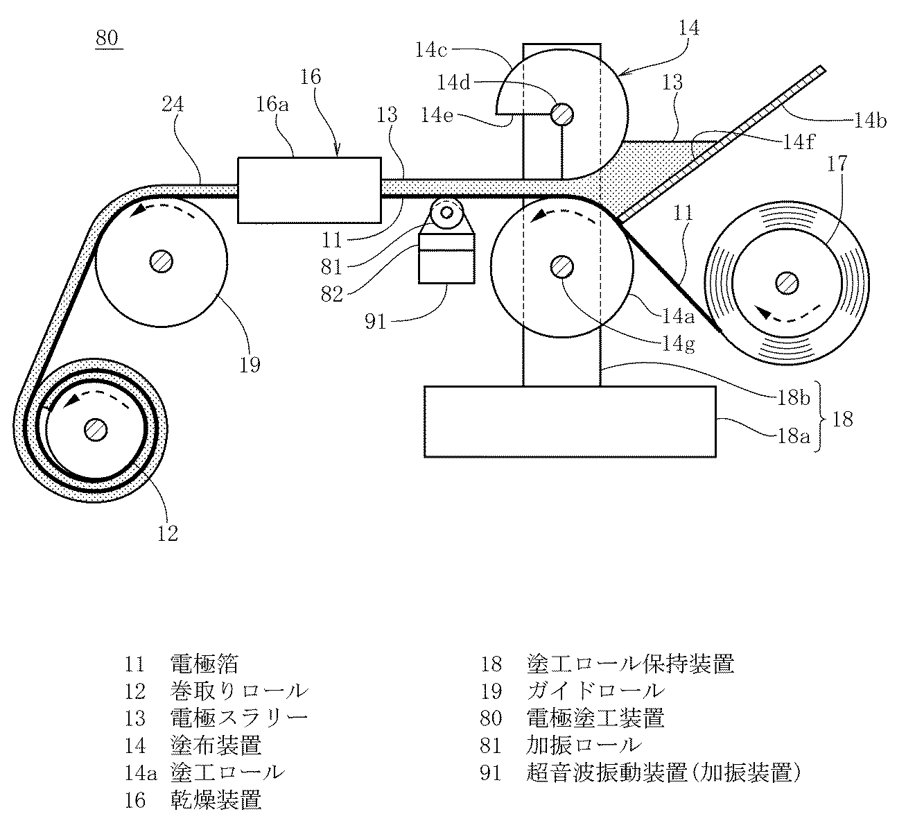
表1から明らかなように、正極活物質としてLCOを用いた場合、加振ロールに振動を加えなかった比較例1では放電容量が86mAh/gと低かったのに対し、加振ロールやガイドロールに振動を加えた実施例1〜3では放電容量が125〜131mAh/gと増大した。また、正極活物質としてNMCを用いた場合、加振ロールに振動を加えなかった比較例2では放電容量が71mAh/gと低かったのに対し、加振ロールに振動を加えた実施例4では放電容量が125mAh/gと増大した。また、正極活物質としてLMOを用いた場合、加振ロールに振動を加えなかった比較例3では放電容量が54mAh/gと低かったのに対し、加振ロールに振動を加えた実施例5では放電容量が98mAh/gと増大した。 As is apparent from Table 1, when LCO was used as the positive electrode active material, the discharge capacity was low at 86 mAh / g in Comparative Example 1 where no vibration was applied to the vibration roll, whereas the vibration roll or guide roll In Examples 1 to 3 in which vibration was applied to the discharge capacity, the discharge capacity increased to 125 to 131 mAh / g. Further, when NMC was used as the positive electrode active material, the discharge capacity was low at 71 mAh / g in Comparative Example 2 in which vibration was not applied to the vibrating roll, whereas in Example 4 in which vibration was applied to the vibrating roll. The discharge capacity increased to 125 mAh / g. Further, when LMO was used as the positive electrode active material, the discharge capacity was low at 54 mAh / g in Comparative Example 3 in which vibration was not applied to the vibrating roll, whereas in Example 5 in which vibration was applied to the vibrating roll. The discharge capacity increased to 98 mAh / g.
また、正極活物質としてLFPを用いた場合、加振ロールに振動を加えなかった比較例4では放電容量が90mAh/gと低かったのに対し、加振ロールに振動を加えた実施例6では放電容量が133mAh/gと増大した。また、負極活物質として天然黒鉛及びSiOを用いた場合、加振ロールに振動を加えなかった比較例5では放電容量が71mAh/gと低かったのに対し、加振ロールに振動を加えた実施例7では放電容量が125mAh/gと増大した。更に、負極活物質としてLTOを用いた場合、加振ロールに振動を加えなかった比較例6では放電容量が95mAh/gと低かったのに対し、加振ロールに振動を加えた実施例8では放電容量が129mAh/gと増大した。上述のことから、電極スラリーの乾燥前又は乾燥中、或いは乾燥前及び乾燥中に、電極スラリーに所定の周波数及び出力の振動を加えることにより、電極スラリーを乾燥させて得られた活物質層を有するラミネートセル(リチウムイオン二次電池)の放電容量が増大することが分かった。これは、電極箔に塗布された電極スラリー中で活物質等を均質な状態に保ったまま、電極スラリーを乾燥できたからであると考えられる。 In addition, when LFP was used as the positive electrode active material, the discharge capacity was low at 90 mAh / g in Comparative Example 4 in which vibration was not applied to the vibrating roll, whereas in Example 6 in which vibration was applied to the vibrating roll. The discharge capacity increased to 133 mAh / g. Moreover, when natural graphite and SiO were used as the negative electrode active material, the discharge capacity was low at 71 mAh / g in Comparative Example 5 in which vibration was not applied to the vibration roll, whereas vibration was applied to the vibration roll. In Example 7, the discharge capacity increased to 125 mAh / g. Furthermore, when LTO was used as the negative electrode active material, the discharge capacity was low at 95 mAh / g in Comparative Example 6 in which vibration was not applied to the vibrating roll, whereas in Example 8 in which vibration was applied to the vibrating roll. The discharge capacity increased to 129 mAh / g. From the above, the active material layer obtained by drying the electrode slurry by applying vibrations of a predetermined frequency and output to the electrode slurry before or during drying of the electrode slurry, or before and during drying. It has been found that the discharge capacity of the laminate cell (lithium ion secondary battery) is increased. This is considered to be because the electrode slurry could be dried while keeping the active material and the like in a homogeneous state in the electrode slurry applied to the electrode foil.
10,50,80 電極塗工装置
11 電極箔
12 巻取りロール
13 電極スラリー
14 塗布装置
14a 塗工ロール
16 乾燥装置
18 塗工ロール保持装置
19 ガイドロール
21,51,91 超音波振動装置(加振装置)
81 加振ロール
DESCRIPTION OF
81 Excitation roll
Claims (10)
前記電極箔に塗布された前記電極スラリーの乾燥前又は乾燥中のいずれか一方又は双方に、前記電極スラリーに振動を加えることを特徴とするリチウムイオン二次電池の電極塗工方法。 In the electrode coating method for a lithium ion secondary battery, the electrode foil in which the active material and the conductive additive are dispersed is applied to the electrode foil and dried while the electrode foil is drawn out by a winding roll.
An electrode coating method for a lithium ion secondary battery, wherein vibration is applied to the electrode slurry before or during drying of the electrode slurry applied to the electrode foil.
前記塗布装置と前記乾燥装置との間、或いは前記乾燥装置と前記巻取りロールとの間に、前記電極スラリーに振動を加える加振装置が設けられたことを特徴とするリチウムイオン二次電池の電極塗工装置。 An application device for applying an electrode slurry, in which an active material and a conductive additive are dispersed, to the electrode foil while the electrode foil is drawn out by a winding roll, and a drying device for drying the electrode slurry applied to the electrode foil in this order. In the lithium ion secondary battery electrode coating apparatus provided,
A lithium ion secondary battery comprising a vibration device for applying vibration to the electrode slurry between the coating device and the drying device or between the drying device and the winding roll. Electrode coating device.
Priority Applications (1)
| Application Number | Priority Date | Filing Date | Title |
|---|---|---|---|
| JP2013057581A JP2014182971A (en) | 2013-03-21 | 2013-03-21 | Method and apparatus for coating electrode of lithium ion secondary battery |
Applications Claiming Priority (1)
| Application Number | Priority Date | Filing Date | Title |
|---|---|---|---|
| JP2013057581A JP2014182971A (en) | 2013-03-21 | 2013-03-21 | Method and apparatus for coating electrode of lithium ion secondary battery |
Publications (1)
| Publication Number | Publication Date |
|---|---|
| JP2014182971A true JP2014182971A (en) | 2014-09-29 |
Family
ID=51701472
Family Applications (1)
| Application Number | Title | Priority Date | Filing Date |
|---|---|---|---|
| JP2013057581A Pending JP2014182971A (en) | 2013-03-21 | 2013-03-21 | Method and apparatus for coating electrode of lithium ion secondary battery |
Country Status (1)
| Country | Link |
|---|---|
| JP (1) | JP2014182971A (en) |
Cited By (13)
| Publication number | Priority date | Publication date | Assignee | Title |
|---|---|---|---|---|
| KR20160069458A (en) * | 2014-12-08 | 2016-06-16 | 삼성에스디아이 주식회사 | Negative electrode for rechargeable lithium battery and rechargeable lithium battery |
| JP2016126854A (en) * | 2014-12-26 | 2016-07-11 | 株式会社豊田自動織機 | Electrode manufacturing method and electrode manufacturing apparatus |
| WO2017061514A1 (en) * | 2015-10-05 | 2017-04-13 | 積水化学工業株式会社 | Negative electrode material, negative electrode, and lithium ion secondary battery |
| CN107112443A (en) * | 2014-09-26 | 2017-08-29 | 江森自控科技公司 | High energy density prismatic battery cells and battery modules |
| CN110813627A (en) * | 2019-11-14 | 2020-02-21 | 江苏英能新能源科技有限公司 | Prevent coating machine for lithium cell processing of waste gas loss |
| CN112542574A (en) * | 2020-12-21 | 2021-03-23 | 力神电池(苏州)有限公司 | System for implementing double-coating lithium battery pole piece production process |
| CN113102161A (en) * | 2021-04-26 | 2021-07-13 | 般若涅利(北京)装备技术有限公司 | High viscosity battery slurry coating device and coating method thereof |
| WO2021140888A1 (en) | 2020-01-06 | 2021-07-15 | 日本スピンドル製造株式会社 | Coating device, partition member, and coating method |
| CN113663866A (en) * | 2021-09-16 | 2021-11-19 | 斯诺良能新能源科技(北京)有限公司 | Coating method and coating device for high-viscosity slurry in secondary battery coating process |
| CN113751287A (en) * | 2021-08-27 | 2021-12-07 | 安徽德亚电池有限公司 | A battery pole piece coating device |
| CN115084665A (en) * | 2022-08-01 | 2022-09-20 | 实联长宜淮安科技有限公司 | Method for improving compaction density of lithium battery pole piece |
| CN116422540A (en) * | 2023-05-16 | 2023-07-14 | 广州市新栋力超声电子设备有限公司 | A foil coating treatment device suitable for battery pole piece production |
| DE102025103271A1 (en) * | 2025-01-29 | 2026-07-30 | Bayerische Motoren Werke Aktiengesellschaft | DEVICE FOR PRODUCING AN ELECTRODE FILM |
-
2013
- 2013-03-21 JP JP2013057581A patent/JP2014182971A/en active Pending
Cited By (19)
| Publication number | Priority date | Publication date | Assignee | Title |
|---|---|---|---|---|
| CN107112443A (en) * | 2014-09-26 | 2017-08-29 | 江森自控科技公司 | High energy density prismatic battery cells and battery modules |
| JP7053130B2 (en) | 2014-12-08 | 2022-04-12 | 三星エスディアイ株式会社 | Negative electrode for lithium-ion secondary battery, and lithium-ion secondary battery |
| KR102434887B1 (en) * | 2014-12-08 | 2022-08-19 | 삼성에스디아이 주식회사 | Negative electrode for rechargeable lithium battery and rechargeable lithium battery |
| JP2016110876A (en) * | 2014-12-08 | 2016-06-20 | 三星エスディアイ株式会社Samsung SDI Co., Ltd. | Negative electrode for lithium ion secondary battery and lithium ion secondary battery |
| KR20160069458A (en) * | 2014-12-08 | 2016-06-16 | 삼성에스디아이 주식회사 | Negative electrode for rechargeable lithium battery and rechargeable lithium battery |
| JP2016126854A (en) * | 2014-12-26 | 2016-07-11 | 株式会社豊田自動織機 | Electrode manufacturing method and electrode manufacturing apparatus |
| WO2017061514A1 (en) * | 2015-10-05 | 2017-04-13 | 積水化学工業株式会社 | Negative electrode material, negative electrode, and lithium ion secondary battery |
| JPWO2017061514A1 (en) * | 2015-10-05 | 2018-08-02 | 積水化学工業株式会社 | Negative electrode material, negative electrode and lithium ion secondary battery |
| CN110813627A (en) * | 2019-11-14 | 2020-02-21 | 江苏英能新能源科技有限公司 | Prevent coating machine for lithium cell processing of waste gas loss |
| WO2021140888A1 (en) | 2020-01-06 | 2021-07-15 | 日本スピンドル製造株式会社 | Coating device, partition member, and coating method |
| CN112542574A (en) * | 2020-12-21 | 2021-03-23 | 力神电池(苏州)有限公司 | System for implementing double-coating lithium battery pole piece production process |
| CN113102161A (en) * | 2021-04-26 | 2021-07-13 | 般若涅利(北京)装备技术有限公司 | High viscosity battery slurry coating device and coating method thereof |
| CN113102161B (en) * | 2021-04-26 | 2024-03-01 | 般若涅利(北京)装备技术有限公司 | High-viscosity battery paste coating device and coating method thereof |
| CN113751287A (en) * | 2021-08-27 | 2021-12-07 | 安徽德亚电池有限公司 | A battery pole piece coating device |
| CN113663866A (en) * | 2021-09-16 | 2021-11-19 | 斯诺良能新能源科技(北京)有限公司 | Coating method and coating device for high-viscosity slurry in secondary battery coating process |
| CN115084665A (en) * | 2022-08-01 | 2022-09-20 | 实联长宜淮安科技有限公司 | Method for improving compaction density of lithium battery pole piece |
| CN115084665B (en) * | 2022-08-01 | 2024-12-27 | 实联长宜淮安科技有限公司 | A method for improving the compaction density of lithium battery pole pieces |
| CN116422540A (en) * | 2023-05-16 | 2023-07-14 | 广州市新栋力超声电子设备有限公司 | A foil coating treatment device suitable for battery pole piece production |
| DE102025103271A1 (en) * | 2025-01-29 | 2026-07-30 | Bayerische Motoren Werke Aktiengesellschaft | DEVICE FOR PRODUCING AN ELECTRODE FILM |
Similar Documents
| Publication | Publication Date | Title |
|---|---|---|
| KR101863518B1 (en) | Method of manufacturing lithium-ion secondary battery electrode sheet | |
| JP6183360B2 (en) | Electrode of lithium ion secondary battery and lithium ion secondary battery using the same | |
| US20150171421A1 (en) | Electrode for lithium ion secondary cell, method for preparing paste for said electrode and method for manufacturing said electrode | |
| JP2019535110A (en) | Anode slurry for lithium ion battery | |
| JP2019537212A (en) | Battery anode slurry preparation method | |
| CN113193298B (en) | Preparation method and application of ultrathin carbon-coated diaphragm | |
| JP6700204B2 (en) | Electrode manufacturing method | |
| JP2007080652A (en) | Slurry for forming lithium ion battery electrode and lithium ion battery | |
| JP2014044921A (en) | Lithium ion secondary battery, and method for manufacturing the same | |
| JP2014197479A (en) | Positive electrode for lithium ion secondary battery, method for manufacturing the same, and lithium ion secondary battery formed by use thereof | |
| JP5375959B2 (en) | Positive electrode plate, battery, and method for manufacturing positive electrode plate | |
| JP7214765B2 (en) | METHOD FOR MANUFACTURING ELECTRODE FOR SECONDARY BATTERY | |
| CN114975876B (en) | Method for producing electrode for secondary battery | |
| JP7145501B2 (en) | METHOD FOR MANUFACTURING ELECTRODE FOR SECONDARY BATTERY | |
| JP2013161689A (en) | Secondary battery electrode and manufacturing method of the same | |
| KR20150010617A (en) | Method and equipment for manufacturing electrode sheet | |
| JP2015095423A (en) | Electrode material for lithium secondary battery and lithium secondary battery | |
| JP2012064542A (en) | Active material paste for batteries, evaluation method of dispersibility of active material paste for batteries, management method of dispersibility of active material paste for batteries, and manufacturing method of electrode plate | |
| JP5998428B2 (en) | Non-aqueous electrolyte secondary battery positive electrode, non-aqueous electrolyte secondary battery, non-aqueous electrolyte secondary battery positive electrode manufacturing method, non-aqueous electrolyte secondary battery positive ink, non-aqueous electrolyte secondary battery For manufacturing positive electrode for automobile | |
| JP6954224B2 (en) | Manufacturing method of all-solid-state battery | |
| JP6487369B2 (en) | Conductive paste for preparing positive electrode of lithium ion secondary battery | |
| JP5545088B2 (en) | Method for forming solid electrolyte-containing film | |
| JP7796354B2 (en) | Dry Powder Bed | |
| JP2000353516A (en) | Manufacturing method of non-aqueous electrolyte secondary battery | |
| JP2012252810A (en) | Manufacturing method of positive electrode plate |