JP2014146435A - Connector structure - Google Patents
Connector structure Download PDFInfo
- Publication number
- JP2014146435A JP2014146435A JP2013012863A JP2013012863A JP2014146435A JP 2014146435 A JP2014146435 A JP 2014146435A JP 2013012863 A JP2013012863 A JP 2013012863A JP 2013012863 A JP2013012863 A JP 2013012863A JP 2014146435 A JP2014146435 A JP 2014146435A
- Authority
- JP
- Japan
- Prior art keywords
- electric wire
- shield
- connector structure
- housing
- seal member
- Prior art date
- Legal status (The legal status is an assumption and is not a legal conclusion. Google has not performed a legal analysis and makes no representation as to the accuracy of the status listed.)
- Granted
Links
- 239000011248 coating agent Substances 0.000 claims abstract description 37
- 238000000576 coating method Methods 0.000 claims abstract description 37
- 238000009413 insulation Methods 0.000 claims abstract description 14
- 230000002093 peripheral effect Effects 0.000 claims description 22
- 238000003780 insertion Methods 0.000 claims description 19
- 230000037431 insertion Effects 0.000 claims description 19
- 239000004020 conductor Substances 0.000 claims description 11
- 238000007789 sealing Methods 0.000 claims description 9
- 238000002788 crimping Methods 0.000 claims description 2
- 230000000149 penetrating effect Effects 0.000 claims 1
- XLYOFNOQVPJJNP-UHFFFAOYSA-N water Substances O XLYOFNOQVPJJNP-UHFFFAOYSA-N 0.000 abstract description 10
- 238000001125 extrusion Methods 0.000 abstract 1
- 230000007774 longterm Effects 0.000 abstract 1
- 229910052751 metal Inorganic materials 0.000 description 48
- 239000002184 metal Substances 0.000 description 48
- 239000013013 elastic material Substances 0.000 description 3
- 238000000034 method Methods 0.000 description 3
- 238000009422 external insulation Methods 0.000 description 2
- 239000000463 material Substances 0.000 description 2
- 239000007769 metal material Substances 0.000 description 2
- 229920003002 synthetic resin Polymers 0.000 description 2
- 239000000057 synthetic resin Substances 0.000 description 2
- 229910000838 Al alloy Inorganic materials 0.000 description 1
- 239000004698 Polyethylene Substances 0.000 description 1
- 238000005452 bending Methods 0.000 description 1
- 238000012986 modification Methods 0.000 description 1
- 230000004048 modification Effects 0.000 description 1
- -1 polyethylene Polymers 0.000 description 1
- 229920000573 polyethylene Polymers 0.000 description 1
- 229920005989 resin Polymers 0.000 description 1
- 239000011347 resin Substances 0.000 description 1
- 238000004078 waterproofing Methods 0.000 description 1
Images


Classifications
-
- H—ELECTRICITY
- H02—GENERATION; CONVERSION OR DISTRIBUTION OF ELECTRIC POWER
- H02G—INSTALLATION OF ELECTRIC CABLES OR LINES, OR OF COMBINED OPTICAL AND ELECTRIC CABLES OR LINES
- H02G15/00—Cable fittings
- H02G15/013—Sealing means for cable inlets
-
- H—ELECTRICITY
- H02—GENERATION; CONVERSION OR DISTRIBUTION OF ELECTRIC POWER
- H02G—INSTALLATION OF ELECTRIC CABLES OR LINES, OR OF COMBINED OPTICAL AND ELECTRIC CABLES OR LINES
- H02G3/00—Installations of electric cables or lines or protective tubing therefor in or on buildings, equivalent structures or vehicles
- H02G3/22—Installations of cables or lines through walls, floors or ceilings, e.g. into buildings
Abstract
Description
本発明は、接続対象物の一方から他方に向かって挿通させた電線を該接続対象物に接続するためのコネクタ構造に関する。 The present invention relates to a connector structure for connecting an electric wire inserted from one connection object to the other to the connection object.
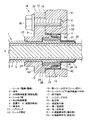
従来、機器同士を接続する電線のコネクタ構造として、例えば自動車(特に、電気自動車やハイブリッド自動車)において、モータやバッテリ、インバータ等の機器同士がシールド電線によって接続され、このシールド電線と機器のケースとをアース接続するためのシールドコネクタ構造が提案されている(例えば、特許文献1参照)。特許文献1に記載されたシールドコネクタ構造100は、図7に示すように、シールド電線1と接続対象物の金属ケース6とを接続するとともに、接続部の防水を図るものである。シールド電線1は、導体2と、導体2の周囲を覆う内部絶縁被覆3と、内部絶縁被覆3の周囲に設けられる編組等の導体からなるシールド部4と、シールド部4の周囲を覆う外部絶縁被覆5と、を有した同軸ケーブルである。金属ケース6には、シールド電線1を挿通させる挿通孔7と、ハウジング101を固定するボルト106が螺合するボルト孔8と、が設けられている。
Conventionally, as a connector structure of electric wires for connecting devices, for example, in an automobile (particularly, an electric vehicle or a hybrid vehicle), devices such as a motor, a battery, and an inverter are connected by a shielded wire. A shield connector structure for grounding is proposed (for example, see Patent Document 1). As shown in FIG. 7, the
このシールドコネクタ構造100は、シールド電線1を挿通させるとともに金属ケース6に固定されるハウジング101と、シールド電線1のシールド部4と金属ケース6とを電気的に接続するシールド部材102と、シールド部材102の内面とシールド電線1の外部絶縁被覆5外面との間に介挿される第一シール部材103と、シールド部材102の外面と金属ケース6の挿通孔7の内面との間に介挿される第二シール部材104と、シールド部材102に接続されたシールド部4を覆うシールドパイプ105と、ハウジング101を金属ケース6に固定するボルト106と、を備えて構成されている。
The
ハウジング101は、金属ケース6の一方側(外部側)に固定されるとともに、金属ケース6との間にシールド部材102を挟んで保持するものであって、シールド電線1を挿通させる挿通部111と、この挿通部111よりも金属ケース6の他方側(内部側)に延出して挿通孔7に入り込む筒状突部112と、挿通部111の径方向外側に延びて金属ケース6に固定されるフランジ部113と、を有して形成されている。
The
第一シール部材103は、ゴム等の弾性材料から全体筒状に形成されるとともに、その内周面及び外周面に凹凸環状のリップ部を有し、内周面の複数のリップ部をシールド電線1の外部絶縁被覆5外面に密接させるとともに、外周面の複数のリップ部をシールド部材102及びハウジング101の筒状突部112の各内面に密接させ、これによりシールド電線1とシールド部材102及びハウジング101との間をシールするように構成されている。
The
以上のように特許文献1に記載された従来のシールドコネクタ構造100において、シールド電線1は、ハウジング101によって金属ケース6に機械的に接続されるとともに、シールド部材102を介してシールド部4が金属ケース6に電気的にアース接続されている。さらに、第一シール部材103及び第二シール部材104によってシールされることで、シールド電線1と金属ケース6との接続部における止水が図られ、金属ケース6の外部から内部に向かう水等の浸入が防止できるようになっている。
As described above, in the conventional
しかしながら、特許文献1に開示されている従来のコネクタ構造では、止水性能を保持するためにシールド電線1を強く締め付ける第一シール部材103を使用しており、第一シール部材103がシールド電線1を強く締め付けることによりシールド電線103の外部絶縁被覆5が変形しやすく、図8に示すように、第一シール部材103よりも金属ケース6の外側又は内側に向かって外部絶縁被覆5が押し出されるように移動し、第一シール部材103位置における電線の外径が小さくなる、いわゆる電線やせが生じ、その結果、第一シール部材103とシールド電線1との密接が弱くなって止水性能が低下するという問題があった。
However, in the conventional connector structure disclosed in Patent Document 1, the
本発明の目的は、上記のような問題点に着目し、止水性能を維持することができるコネクタ構造を提供することである。 An object of the present invention is to provide a connector structure capable of maintaining water stopping performance by paying attention to the above problems.
上記課題を解決するために、本発明のコネクタ構造は、導体と絶縁被覆とを有した電線を接続対象物の挿通孔に一方から他方へ挿通させて該接続対象物に接続するためのコネクタ構造であって、前記電線を挿通させるとともに前記接続対象物の一方側に固定されるハウジングと、前記ハウジング内面と前記電線の外面との間に介挿されるシール部材と、前記シール部材の一方側において前記電線を締め付ける締付部材と、を備えて構成され、前記ハウジングは、ハウジング本体と、前記接続対象物に固定するための固定部と、前記ハウジング本体を貫通して前記電線を一方側から他方側へ挿通させる電線案内部と、を有し前記シール部材は、前記電線に沿う筒状に形成されるとともに前記電線の外周面に密接する第一密接部と、前記ハウジング本体の内周面に密接する第二密接部と、を有し、前記締付部材は、加締めにより縮径されて前記電線の絶縁被覆を押圧する環状部を有し、該環状部が前記電線案内部の内側に位置して設けられていることを特徴とする。 In order to solve the above problems, the connector structure of the present invention is a connector structure for connecting an electric wire having a conductor and an insulating coating from one side to the other through an insertion hole of the connection target and connecting to the connection target. A housing that allows the wire to be inserted and is fixed to one side of the connection object; a seal member that is interposed between the housing inner surface and the outer surface of the wire; and one side of the seal member A fastening member for fastening the electric wire, and the housing includes a housing main body, a fixing portion for fixing the electric wire to the connection object, and the electric wire passing through the housing main body from one side to the other. A first guide portion that is formed in a cylindrical shape along the electric wire and is in close contact with the outer peripheral surface of the electric wire, and the housing. A second close contact portion that is in close contact with the inner peripheral surface of the main body, and the fastening member includes an annular portion that is reduced in diameter by caulking and presses the insulating coating of the electric wire, and the annular portion is It is located inside an electric wire guide part, It is characterized by the above-mentioned.
本発明によれば、シール部材の一方側において締付部材が電線を締め付けることにより、シール部材に締め付けられた電線の被覆が一方側に押し出されず、電線やせを防止することができる。 According to the present invention, when the fastening member fastens the electric wire on one side of the seal member, the coating of the electric wire fastened to the seal member is not pushed out to the one side, and the electric wire can be prevented from being thin.
請求項1に記載のコネクタ構造において、前記締付部材は、前記電線案内部の側面に他方側から当接する鍔状部を有することが好ましい。 The connector structure according to claim 1, wherein the tightening member preferably has a hook-shaped portion that comes into contact with a side surface of the wire guide portion from the other side.
このような構成によれば、締付部材の鍔状部が電線案内部に当接して電線の一方側への移動を規制することで、電線が屈曲されたり、引っ張られたりしても接続対象物やハウジングからの電線の脱落を防止することができる。 According to such a configuration, even if the electric wire is bent or pulled, the hooked portion of the tightening member abuts on the electric wire guide portion and restricts the movement of the electric wire to one side. It is possible to prevent the wires from dropping from the object or the housing.
請求項1又は2に記載のコネクタ構造において、前記シール部材の他方側において前記電線を締め付ける他方側締付部材をさらに備えることが好ましい。 3. The connector structure according to claim 1, further comprising an other side fastening member for fastening the electric wire on the other side of the seal member.
このような構成によれば、シール部材の他方側においても他方側締付部材が電線を締め付けることにより、シール部材に締め付けられた電線の被覆が一方側だけではなく他方側にも押し出されず、電線やせを一層防止することができることから、止水性能を維持することができる。 According to such a configuration, the other side tightening member tightens the electric wire also on the other side of the sealing member, so that the coating of the electric wire tightened on the sealing member is not pushed out not only on one side but also on the other side. Since it can prevent further thinning, the water stop performance can be maintained.
請求項3に記載のコネクタ構造において、前記電線は、前記絶縁被覆の外側に設けられるシールド部と、該シールド部の外側に設けられる外部絶縁被覆と、を有するシールド電線であって、前記シールド部と前記接続対象物とを接続する導電性かつ筒状のシールド部材をさらに備え、他方側締付部材は、前記シールド部材と前記電線とを加締めて固定する圧着部材であることが好ましい。
4. The connector structure according to
このような構成によれば、シール部材を挟んで電線の一方側と他方側とにおいて締付部材及び他方側締付部材が電線を締め付けることにより、シールドコネクタにおいても、電線やせによるシール圧低下を防止することができ、止水性能を保持することができる。 According to such a configuration, the clamping member and the other side clamping member clamp the electric wire on one side and the other side of the electric wire with the sealing member interposed therebetween, so that the sealing pressure is reduced due to the electric wire thinning even in the shield connector. It is possible to prevent water retention performance.
以上のような本発明のコネクタ構造によれば、シール部材に隣り合った位置において、締付部材が電線を締め付けることにより電線やせを抑制することができ、長期にわたって止水性能を維持することが可能となる。 According to the connector structure of the present invention as described above, at the position adjacent to the seal member, the tightening member can suppress the thinning of the electric wire by tightening the electric wire, and can maintain the waterproof performance for a long period of time. It becomes possible.
以下、本発明の一実施形態にかかるコネクタ構造を、図1〜図6を参照して説明する。本実施形態のコネクタ構造は、自動車、特に、電動モータの駆動力によって走行する電気自動車や、エンジンと電動モータとの双方の駆動力で走行するハイブリッド車において、モータとインバータとの間やインバータとバッテリーとの間等をシールド電線1で繋ぐ場合に、シールド電線1をアース接続するとともに、この接続部の防水を図るのに適した接続構造である。 Hereinafter, a connector structure according to an embodiment of the present invention will be described with reference to FIGS. The connector structure of the present embodiment is an automobile, in particular, an electric vehicle that runs with the driving force of an electric motor, or a hybrid vehicle that runs with the driving force of both an engine and an electric motor. When connecting the battery and the like with the shielded electric wire 1, the shielded electric wire 1 is connected to the ground, and the connection structure is suitable for waterproofing the connecting portion.
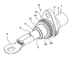
シールド電線1は、図1に示すように、複数の素線を撚った撚線等からなる導体2と、導体2の周囲を覆う絶縁性の合成樹脂等からなる絶縁被覆3と、絶縁被覆3の周囲に設けられる編組等の導体からなるシールド部4と、シールド部4の周囲を覆う絶縁性の合成樹脂等からなる外部絶縁被覆5と、を有した同軸ケーブルである。一方、接続対象物としてのモータやインバータ、バッテリー等は、その外殻を構成する金属ケース6を有し、金属ケース6には、シールド電線1を挿通させる挿通孔7が設けられている。
As shown in FIG. 1, the shielded electric wire 1 includes a
シールド電線1は、図1及び図2に示すように、金属ケース6の外部側(一方側)から挿通孔7を介して内部側(他方側)に挿通されるとともに、内部側の先端部における導体2に端子金具9が固定され、この端子金具9が金属ケース6内の図示しない電気接続部に接続されている。また、シールド電線1のシールド部4は、先端部において外部絶縁被覆5が除去されて露出されるとともに、後述するシールド部材12を介して金属ケース6にアース接続されており、これらのシールド部4及びシールド部材12によって電磁波を遮蔽し、接続部からのノイズの漏えいや侵入が防止できるようになっている。
As shown in FIGS. 1 and 2, the shielded electric wire 1 is inserted from the outer side (one side) of the metal case 6 to the inner side (the other side) through the
コネクタ10は、図1〜図3に示すように、シールド電線1を挿通させるとともに金属ケース6の外面に固定されるハウジング11と、シールド電線1のシールド部4と金属ケース6とを接続する導電性かつ筒状のシールド部材12と、シールド部材12の内面とシールド電線1の外部絶縁被覆5の外面との間に介挿される第一シール部材13と、シールド部材12の外面と金属ケース6の挿通孔7の内面との間に介挿される第二シール部材14と、シールド電線1のシールド部4とシールド部材12とを加締めて固定する環状のシールドパイプ(他方側締付部材であり圧着部材)15と、ハウジング11を金属ケース6に固定するためのボルト16と、を備えて構成されている。
As shown in FIGS. 1 to 3, the
ハウジング11は、アルミニウム合金等の金属から一体成形されたダイカスト部品であって、金属ケース6の外面に対してシールド部材12を挟み込んで導通させるハウジング本体21と、金属ケース6の外方から該金属ケース6に固定される固定部22と、ハウジング本体21を貫通してシールド電線1を挿通させる電線案内部23と、ハウジング本体21から金属ケース6の挿通孔7内に延びてシールド部材12の内側に位置する筒状の延出部24と、を有して形成されている。なお、ハウジング11は、金属材に限らず、シールド部材12や第一シール部材13を保持するものであれば樹脂製であってもよい。
The
シールド部材12は、導電性の金属材料からなり、金属ケース6の内部側から外部側に向かって三段に径が大きくなる段付き筒状に形成されている。具体的には、図6にも示すように、シールド部材12は、シールド電線1のシールド部4に接続される第一筒状部31と、この第一筒状部31よりもハウジング11の側(一方側であり金属ケース6の外部側)に位置して径大に設けられる第二筒状部32と、この第二筒状部32よりもさらに一方側に位置して径大に設けられる第三筒状部33と、第一筒状部31と第二筒状部32とを連結する第一段付き部34と、第二筒状部32と第三筒状部33とを連結する第二段付き部35と、第三筒状部33に連続して折れ曲がり金属ケース6の外面に沿う第三段付き部36と、を有して形成されている。
The
第一シール部材13は、図4及び図6にも示すように、ゴム等の弾性材料から全体筒状に形成されるとともに、シールド電線1に沿って外部絶縁被覆5の外周面に密接する第一密接部41と、延出部24の内周面と第二筒状部32内周面とに密接する第二密接部42とを有して形成されている。第一シール部材13における第一密接部41には、三条の環状リップ43が形成され、これらの環状リップ43が潰されつつ外部絶縁被覆5の外周面に押しつけられることで、シールド電線1との間がシールされている。また、第二密接部42には、二条の環状リップ44が形成され、これらの環状リップ44が潰されつつ延出部24内周面と第二筒状部32内周面とに押しつけられることで、ハウジング本体21とシールド部材12との間がシールされている。
As shown in FIGS. 4 and 6, the
第二シール部材14は、ゴム等の弾性材料から全体筒状に形成されるとともに、その内周面及び外周面にそれぞれ二条の環状リップが形成され、内周面の環状リップが潰されつつ第二筒状部32外周面に押しつけられることで、シールド部材12との間がシールされ、外周面の環状リップが潰されつつ挿通孔7内周面に押しつけられることで、金属ケース6との間がシールされている。
The
以上のように挿通孔7内部において、図4に示すように、外部絶縁被覆5の外周面から挿通孔7内周面に向かって順に、金属ケースの外部側(一方側)において、第一シール部材13の第一密接部41、第一シール部材13の第二密接部42、ハウジング11の延出部24、第三筒状部33が同心円状に位置し、金属ケースの内部側(他方側)において、第一シール部材13の第一密接部41、第一シール部材13の第二密接部42、シールド部材12の第二筒状部32、第二シール部材14が同心円状に位置し、これらの径方向に隣り合う部位同士が互いに密接されることで、シールド電線1が止水された状態で金属ケース6に接続されるようになっている。
As described above, in the
また、シールド電線1は、第一シール部材13に隣り合って金属ケース6の外部側(一方側)において、金属製の締付部材17により締め付けられ、シール部材の内部側(他方側)において、金属製のシールドパイプ15により締め付けられている。締付部材17は、加締めにより縮径されて前記電線の絶縁被覆を押圧する外部側環状部51と、外部側鍔状部52と、を有して形成され、電線案内部23の内側側面に内部側(他方側)から当接している。シールドパイプ15は、内部側環状部53と、内部側鍔状部54と、を有して形成され、内部側環状部53によって、シールド電線1とシールド部材12の第一筒状部31とを加締めて固定するとともに、内部側鍔状部54によって金属ケースの内部側(他方側)からシールド部材12の第一段付き部34に当接している。
The shielded electric wire 1 is clamped by a
次に、シールド電線1の金属ケース6への組付け手順の一例を説明する。なお、シールド電線1の組付け手順としては、以下説明するものに限らず、組付け後において図1に示すシールドコネクタ10が構成されていればよいため、以下に示す各手順が適宜に前後してもよい。
Next, an example of the procedure for assembling the shielded electric wire 1 to the metal case 6 will be described. Note that the procedure for assembling the shielded electric wire 1 is not limited to the one described below, and it is only necessary that the
先ず、所定長さに切断したシールド電線1に、ハウジング本体21、締付部材17、第一シール部材13、シールド部材12の順で挿通させる。シールド電線1の先端部における外部絶縁被覆5を皮剥きし、露出させたシールド部4を切断して折り返し、シールド部材12の第一筒状部31の外周に重ねてから、折り返したシールド部4の外側に重ねたシールドパイプ15を加締めて圧着させ、シールド電線1の先端部にシールド部材12を固定してシールド電線1を締付ける。次に、シールド電線1の先端側に向かって第一シール部材13を移動させ、第一シール部材13を外部絶縁被覆5とシールド部材12の第二筒状部32との隙間に圧入する。これによって、第一シール部材13の第一密接部41をシールド電線1の外部絶縁被覆5に密接させ、第二密接部42を第二筒状部32の内面に密接させる。
First, the housing
次に、シールド電線1の先端側に向かって締付部材17を移動させて、締付部材17の外部側環状部51を加締めてシールド電線1に圧着させることにより、シールド電線1を締め付け、さらに、ハウジング本体21を移動させて、シールド部材12及び第一シール部材13と嵌合させる。これによって、ハウジング11のハウジング本体21及び固定部22をシールド部材12の第三段付き部36に当接させ、締付部材17の外部側鍔状部52を電線案内部23の内側側面に当接させる。
Next, the tightening
次に、シールド電線1の先端側から第二シール部材14をシールド部材12の第二筒状部32外周に嵌める。さらに、内部絶縁被覆3を皮剥きして露出させた導体2に端子金具9を圧着しておく。
Next, the
以上によって、図2に示すように、シールド電線1の先端部にハウジング11、シールド部材12、第一シール部材13、第二シール部材14、及びシールドパイプ15が取り付けられ、この状態のシールド電線1を端子金具9の側から金属ケース6の挿通孔7に挿通させる。そして、挿通孔7の内周面に第二シール部材14を摺接させつつシールド電線1を押し込み、シールド部材12の第三筒状部33を挿通孔7に挿入し、シールド部材12の第三段付き部36を金属ケース6の外面に当接させる。次に、ハウジング11の固定部22に挿通させたボルト16を金属ケース6のボルト孔8に螺合し、ハウジング本体21及び固定部22によって金属ケース6の外面に対して第三段付き部36を挟み込み、これによってシールド部材12を金属ケース6に接続させ、シールド電線1の組付けが完了する。
As described above, as shown in FIG. 2, the
以上のような本実施形態によれば、第一シール部材13の外部側において締付部材17がシールド電線1を締め付けることにより、第一シール部材13に締め付けられて変形したシールド電線1の外側絶縁被覆5が外部側に押し出されることが抑制される。従って、締付部材17がシールド電線1を締付けることにより、第一シール部材13により変形した外側絶縁被覆5が移動し、第一シール部材13位置におけるシールド電線1の外径が小さくなる、いわゆる電線やせを抑制することができ、第一シール部材13とシールド電線1とのシール圧を維持して、止水性能を維持することが可能となる。
According to the present embodiment as described above, the outer insulation of the shielded electric wire 1 deformed by being clamped by the
また、本実施形態において、締付部材17の外部側鍔状部52が電線案内部23の内側側面に内部側から当接して、シールド電線1の外部側への移動を抑制することにより、シールド電線1が屈曲されたり、引っ張られたりしても金属ケース6からのシールド電線の脱落を防止することができる。
Moreover, in this embodiment, the outer side hook-shaped
さらに、本実施形態において、シールドパイプ15がシールド電線1を加締めて圧着することにより、シールド電線1の外側絶縁被覆5が外部側だけではなく、内部側にも押し出されることが無い。従って、第一シール部材13によるシール部分の電線やせを一層抑制することができ、長期にわたって止水性能を維持することが可能となる。
Furthermore, in this embodiment, the
また、本実施形態において、締付部材17が金属を用いて形成されており、シールド電線1の被覆として用いられるポリエチレン等よりも高精度に製造することができることから、製造された締付部材17の外部側環状部51の外径における個体差はシールド電線1より小さくなり、締付部材17がシールド電線1を締め付けた際の、外径の個体差も小さくなる。従って、図4及び図8に示すシールド電線1とハウジング11の電線案内部7とのすき間寸法A,Bにおいて、従来のすき間寸法Bよりも本実施形態のすき間寸法Aをより小さく設計することができる。以上のことから、シールド電線1が外部側において屈曲した場合、曲げ方向と反対側のシール圧低下を低減することができる。
Moreover, in this embodiment, since the
なお、上述した実施形態において、電線として同軸ケーブルからなるシールド電線1を例示したが、シールド電線以外の電線を用いたコネクタ構造においても本発明は利用可能である。その場合、12は省略可能であり、他方側締付部材として、締付部材17と同様の部材を用いることができる。
In the above-described embodiment, the shielded electric wire 1 made of a coaxial cable is exemplified as the electric wire. However, the present invention can also be used in a connector structure using an electric wire other than the shielded electric wire. In that case, 12 can be omitted, and a member similar to the
また、接続対象物としては、モータやインバータ、バッテリーなどに限らず、その他の適宜な電気機器であってもよいし、内部に電気部品を備えた電気接続箱であってもよい。 In addition, the connection object is not limited to a motor, an inverter, a battery, or the like, but may be other appropriate electrical equipment, or an electrical connection box having an electrical component inside.
その他、本発明を実施するための最良の構成、方法などは、以上の記載で開示されているが、本発明は、これに限定されるものではない。すなわち、本発明は、主に特定の実施形態に関して特に図示され、且つ、説明されているが、本発明の技術的思想および目的の範囲から逸脱することなく、以上述べた実施形態に対し、形状、材質、数量、その他の詳細な構成において、当業者が様々な変形を加えることができるものである。 In addition, the best configuration, method and the like for carrying out the present invention have been disclosed in the above description, but the present invention is not limited to this. That is, the invention has been illustrated and described primarily with respect to particular embodiments, but may be configured for the above-described embodiments without departing from the scope and spirit of the invention. Various modifications can be made by those skilled in the art in terms of materials, quantity, and other detailed configurations.
従って、上記に開示した形状、材質などを限定した記載は、本発明の理解を容易にするために例示的に記載したものであり、本発明を限定するものではないから、それらの形状、材質などの限定の一部、もしくは全部の限定を外した部材の名称での記載は、本発明に含まれるものである。 Therefore, the description limiting the shape, material, etc. disclosed above is an example for easy understanding of the present invention, and does not limit the present invention. The description by the name of the member which remove | excluded the limitation of one part or all of such is included in this invention.
1 シールド電線(電線)
2 導体
3 内側絶縁被覆(絶縁被覆)
4 シールド部
5 外部絶縁被覆
6 金属ケース(接続対象物)
7 挿通孔
11 ハウジング
12 シールド部材
13 第一シール部材(シール部材)
15 シールドパイプ(他方側締付部材)
17 締付部材
21 ハウジング本体
22 固定部
23 電線案内部
41 第一密接部
42 第二密接部
51 外部側環状部
52 外部側鍔状部(鍔状部)
1 Shielded wire (wire)
2
4
7
15 Shield pipe (Tightening member on the other side)
17 Tightening
Claims (4)
前記電線を挿通させるとともに前記接続対象物の一方側に固定されるハウジングと、
前記ハウジング内面と前記電線の外面との間に介挿されるシール部材と、
前記シール部材の一方側において前記電線を締め付ける締付部材と、を備えて構成され、
前記ハウジングは、
ハウジング本体と、
前記接続対象物に固定するための固定部と、
前記ハウジング本体を貫通して前記電線を一方側から他方側へ挿通させる電線案内部と、を有し
前記シール部材は、
前記電線に沿う筒状に形成されるとともに前記電線の外周面に密接する第一密接部と、
前記ハウジング本体の内周面に密接する第二密接部と、を有し、
前記締付部材は、加締めにより縮径されて前記電線の絶縁被覆を押圧する環状部を有し、該環状部が前記電線案内部の内側に位置して設けられていることを特徴とするコネクタ構造。 A connector structure for connecting an electric wire having a conductor and an insulation coating to the connection object by inserting the wire from one to the other through the insertion hole of the connection object,
A housing that allows the electric wire to pass therethrough and is fixed to one side of the connection object;
A seal member interposed between the inner surface of the housing and the outer surface of the electric wire;
A fastening member for fastening the electric wire on one side of the sealing member, and
The housing is
A housing body;
A fixing portion for fixing to the connection object;
An electric wire guide for penetrating the electric wire from one side to the other through the housing body, and the sealing member
A first close contact portion formed in a cylindrical shape along the electric wire and in close contact with the outer peripheral surface of the electric wire;
A second intimate part in intimate contact with the inner peripheral surface of the housing body,
The tightening member has an annular portion that is reduced in diameter by caulking and presses the insulating coating of the electric wire, and the annular portion is provided inside the electric wire guide portion. Connector structure.
前記シールド部と前記接続対象物とを接続する導電性かつ筒状のシールド部材をさらに備え、
前記他方側締付部材は、前記シールド部材と前記電線とを加締めて固定する圧着部材であることを特徴とする請求項3に記載のコネクタ構造。 The electric wire is a shielded electric wire having a shield portion provided outside the insulating coating, and an external insulating coating provided outside the shield portion,
A conductive and cylindrical shield member for connecting the shield part and the connection object;
The connector structure according to claim 3, wherein the other side fastening member is a crimping member that crimps and fixes the shield member and the electric wire.
Priority Applications (4)
| Application Number | Priority Date | Filing Date | Title |
|---|---|---|---|
| JP2013012863A JP6086381B2 (en) | 2013-01-28 | 2013-01-28 | Connector structure |
| US14/161,862 US20140209377A1 (en) | 2013-01-28 | 2014-01-23 | Connector structure |
| CN201410040461.1A CN103972716A (en) | 2013-01-28 | 2014-01-27 | Connector structure |
| DE102014201522.7A DE102014201522A1 (en) | 2013-01-28 | 2014-01-28 | connector assembly |
Applications Claiming Priority (1)
| Application Number | Priority Date | Filing Date | Title |
|---|---|---|---|
| JP2013012863A JP6086381B2 (en) | 2013-01-28 | 2013-01-28 | Connector structure |
Publications (2)
| Publication Number | Publication Date |
|---|---|
| JP2014146435A true JP2014146435A (en) | 2014-08-14 |
| JP6086381B2 JP6086381B2 (en) | 2017-03-01 |
Family
ID=51163736
Family Applications (1)
| Application Number | Title | Priority Date | Filing Date |
|---|---|---|---|
| JP2013012863A Expired - Fee Related JP6086381B2 (en) | 2013-01-28 | 2013-01-28 | Connector structure |
Country Status (4)
| Country | Link |
|---|---|
| US (1) | US20140209377A1 (en) |
| JP (1) | JP6086381B2 (en) |
| CN (1) | CN103972716A (en) |
| DE (1) | DE102014201522A1 (en) |
Cited By (5)
| Publication number | Priority date | Publication date | Assignee | Title |
|---|---|---|---|---|
| WO2016199650A1 (en) * | 2015-06-08 | 2016-12-15 | 株式会社オートネットワーク技術研究所 | Elastic shielding member for machine |
| JP2017139163A (en) * | 2016-02-04 | 2017-08-10 | 富士電機株式会社 | Connector mounting structure |
| JP2019125471A (en) * | 2018-01-16 | 2019-07-25 | 株式会社オートネットワーク技術研究所 | connector |
| JP2019125470A (en) * | 2018-01-16 | 2019-07-25 | 株式会社オートネットワーク技術研究所 | connector |
| CN112020799A (en) * | 2018-04-23 | 2020-12-01 | 菲尼克斯电气公司 | Plug connector part with shielding sleeve |
Families Citing this family (13)
| Publication number | Priority date | Publication date | Assignee | Title |
|---|---|---|---|---|
| US9318849B2 (en) * | 2011-04-14 | 2016-04-19 | Yazaki Corporation | Shielded connector |
| JP5952607B2 (en) * | 2012-03-27 | 2016-07-13 | 矢崎総業株式会社 | Waterproof shield connector |
| JP6088345B2 (en) * | 2013-05-07 | 2017-03-01 | 矢崎総業株式会社 | connector |
| DE102013009184A1 (en) * | 2013-05-31 | 2014-12-04 | Kostal Kontakt Systeme Gmbh | contact element |
| JP6319633B2 (en) * | 2015-01-28 | 2018-05-09 | 住友電装株式会社 | Connector for equipment |
| JP6492929B2 (en) * | 2015-04-23 | 2019-04-03 | 住友電装株式会社 | connector |
| JP2016210214A (en) * | 2015-04-30 | 2016-12-15 | 住友電装株式会社 | Bracket for grommet |
| US9640965B1 (en) * | 2016-03-25 | 2017-05-02 | Protonex Technology Corporation | Cable gland assembly |
| DE102016109266A1 (en) | 2016-05-06 | 2017-11-09 | Rosenberger Hochfrequenztechnik Gmbh & Co. Kg | Plug connection device with at least one connector |
| DE102016123891B4 (en) | 2016-12-08 | 2018-08-02 | Amphenol-Tuchel Electronics Gmbh | Housing with a housing cover and a cable strain relief |
| JP6577977B2 (en) * | 2017-06-14 | 2019-09-18 | 矢崎総業株式会社 | Packing |
| NL2019583B1 (en) * | 2017-09-20 | 2019-03-28 | Beele Eng Bv | System and method for providing a conduit sealingly to a through-opening in a plate-shaped construction element |
| JP2022059772A (en) * | 2020-10-02 | 2022-04-14 | 住友電装株式会社 | connector |
Citations (1)
| Publication number | Priority date | Publication date | Assignee | Title |
|---|---|---|---|---|
| JPH10112924A (en) * | 1996-10-03 | 1998-04-28 | Yazaki Corp | Termination structure of shield cable |
Family Cites Families (8)
| Publication number | Priority date | Publication date | Assignee | Title |
|---|---|---|---|---|
| US4307926A (en) * | 1979-04-20 | 1981-12-29 | Amp Inc. | Triaxial connector assembly |
| JPH0333977U (en) * | 1989-08-11 | 1991-04-03 | ||
| JP2785714B2 (en) * | 1994-09-08 | 1998-08-13 | 住友電装株式会社 | Fixing structure of rubber stopper for sealing |
| JP3741343B2 (en) * | 1999-01-21 | 2006-02-01 | 矢崎総業株式会社 | Shield connection structure |
| JP3627209B2 (en) | 1999-04-07 | 2005-03-09 | 矢崎総業株式会社 | Shield connector structure |
| JP5697232B2 (en) * | 2010-09-02 | 2015-04-08 | 矢崎総業株式会社 | Shield connector |
| US8523609B2 (en) * | 2011-06-13 | 2013-09-03 | Tyco Electronics Corporation | Photovoltaic connector assembly |
| JP5790492B2 (en) * | 2011-12-28 | 2015-10-07 | 住友電装株式会社 | Wire fixing member |
-
2013
- 2013-01-28 JP JP2013012863A patent/JP6086381B2/en not_active Expired - Fee Related
-
2014
- 2014-01-23 US US14/161,862 patent/US20140209377A1/en not_active Abandoned
- 2014-01-27 CN CN201410040461.1A patent/CN103972716A/en active Pending
- 2014-01-28 DE DE102014201522.7A patent/DE102014201522A1/en not_active Withdrawn
Patent Citations (1)
| Publication number | Priority date | Publication date | Assignee | Title |
|---|---|---|---|---|
| JPH10112924A (en) * | 1996-10-03 | 1998-04-28 | Yazaki Corp | Termination structure of shield cable |
Cited By (10)
| Publication number | Priority date | Publication date | Assignee | Title |
|---|---|---|---|---|
| WO2016199650A1 (en) * | 2015-06-08 | 2016-12-15 | 株式会社オートネットワーク技術研究所 | Elastic shielding member for machine |
| US10136536B2 (en) | 2015-06-08 | 2018-11-20 | Autonetworks Technologies, Ltd. | Resilient shielding member for device |
| JP2017139163A (en) * | 2016-02-04 | 2017-08-10 | 富士電機株式会社 | Connector mounting structure |
| JP2019125471A (en) * | 2018-01-16 | 2019-07-25 | 株式会社オートネットワーク技術研究所 | connector |
| JP2019125470A (en) * | 2018-01-16 | 2019-07-25 | 株式会社オートネットワーク技術研究所 | connector |
| WO2019142762A1 (en) * | 2018-01-16 | 2019-07-25 | 株式会社オートネットワーク技術研究所 | Connector |
| WO2019142759A1 (en) * | 2018-01-16 | 2019-07-25 | 株式会社オートネットワーク技術研究所 | Connector |
| US11201432B2 (en) | 2018-01-16 | 2021-12-14 | Autonetworks Technologies, Ltd. | Connector |
| CN112020799A (en) * | 2018-04-23 | 2020-12-01 | 菲尼克斯电气公司 | Plug connector part with shielding sleeve |
| CN112020799B (en) * | 2018-04-23 | 2022-03-08 | 菲尼克斯电气公司 | Plug connector part with shielding sleeve |
Also Published As
| Publication number | Publication date |
|---|---|
| JP6086381B2 (en) | 2017-03-01 |
| US20140209377A1 (en) | 2014-07-31 |
| DE102014201522A1 (en) | 2014-07-31 |
| CN103972716A (en) | 2014-08-06 |
Similar Documents
| Publication | Publication Date | Title |
|---|---|---|
| JP6086381B2 (en) | Connector structure | |
| JP5886161B2 (en) | Shield connector structure | |
| JP5990454B2 (en) | Shield connector structure | |
| JP5886159B2 (en) | Shield connector structure | |
| JP6234034B2 (en) | Shield connector structure | |
| EP2667458B1 (en) | Connector | |
| US9343821B2 (en) | Terminal waterproofing structure of wire harness | |
| JP5622307B2 (en) | Shield connector | |
| US9325120B2 (en) | Wire harness and connection structure of shield shell and braided shield | |
| JP3952439B2 (en) | Electromagnetic shield structure | |
| JP5697232B2 (en) | Shield connector | |
| US8680396B2 (en) | Oil-cooled equipment harness | |
| US20140106619A1 (en) | Shield connector | |
| US10256577B2 (en) | Connector | |
| JP6000812B2 (en) | Connector for shielded wire | |
| JP2012125009A (en) | Shield cable | |
| JP2013123019A (en) | Shield structure of electric wire | |
| JP3144243U (en) | Coaxial cable connector |
Legal Events
| Date | Code | Title | Description |
|---|---|---|---|
| A621 | Written request for application examination |
Free format text: JAPANESE INTERMEDIATE CODE: A621 Effective date: 20151218 |
|
| A977 | Report on retrieval |
Free format text: JAPANESE INTERMEDIATE CODE: A971007 Effective date: 20160812 |
|
| A131 | Notification of reasons for refusal |
Free format text: JAPANESE INTERMEDIATE CODE: A131 Effective date: 20160823 |
|
| A521 | Request for written amendment filed |
Free format text: JAPANESE INTERMEDIATE CODE: A523 Effective date: 20160927 |
|
| TRDD | Decision of grant or rejection written | ||
| A01 | Written decision to grant a patent or to grant a registration (utility model) |
Free format text: JAPANESE INTERMEDIATE CODE: A01 Effective date: 20170117 |
|
| A61 | First payment of annual fees (during grant procedure) |
Free format text: JAPANESE INTERMEDIATE CODE: A61 Effective date: 20170124 |
|
| R150 | Certificate of patent or registration of utility model |
Ref document number: 6086381 Country of ref document: JP Free format text: JAPANESE INTERMEDIATE CODE: R150 |
|
| R250 | Receipt of annual fees |
Free format text: JAPANESE INTERMEDIATE CODE: R250 |
|
| R250 | Receipt of annual fees |
Free format text: JAPANESE INTERMEDIATE CODE: R250 |
|
| R250 | Receipt of annual fees |
Free format text: JAPANESE INTERMEDIATE CODE: R250 |
|
| LAPS | Cancellation because of no payment of annual fees |