JP2014100532A - Game machine - Google Patents
Game machine Download PDFInfo
- Publication number
- JP2014100532A JP2014100532A JP2013218121A JP2013218121A JP2014100532A JP 2014100532 A JP2014100532 A JP 2014100532A JP 2013218121 A JP2013218121 A JP 2013218121A JP 2013218121 A JP2013218121 A JP 2013218121A JP 2014100532 A JP2014100532 A JP 2014100532A
- Authority
- JP
- Japan
- Prior art keywords
- stop
- signal
- game
- line
- power
- Prior art date
- Legal status (The legal status is an assumption and is not a legal conclusion. Google has not performed a legal analysis and makes no representation as to the accuracy of the status listed.)
- Granted
Links
- 238000001514 detection method Methods 0.000 claims description 319
- 230000000452 restraining effect Effects 0.000 claims description 75
- 230000009471 action Effects 0.000 abstract description 20
- 238000000034 method Methods 0.000 description 203
- 230000008569 process Effects 0.000 description 201
- 238000003860 storage Methods 0.000 description 115
- 238000012545 processing Methods 0.000 description 74
- 239000000758 substrate Substances 0.000 description 67
- 241000219109 Citrullus Species 0.000 description 51
- 235000012828 Citrullus lanatus var citroides Nutrition 0.000 description 51
- 230000007704 transition Effects 0.000 description 41
- 238000012790 confirmation Methods 0.000 description 40
- 238000003780 insertion Methods 0.000 description 39
- 230000037431 insertion Effects 0.000 description 39
- 230000008859 change Effects 0.000 description 34
- 230000001629 suppression Effects 0.000 description 33
- 238000012423 maintenance Methods 0.000 description 30
- NJPPVKZQTLUDBO-UHFFFAOYSA-N novaluron Chemical group C1=C(Cl)C(OC(F)(F)C(OC(F)(F)F)F)=CC=C1NC(=O)NC(=O)C1=C(F)C=CC=C1F NJPPVKZQTLUDBO-UHFFFAOYSA-N 0.000 description 30
- 230000004308 accommodation Effects 0.000 description 29
- 230000000694 effects Effects 0.000 description 22
- 239000003990 capacitor Substances 0.000 description 20
- 238000009429 electrical wiring Methods 0.000 description 19
- 238000010586 diagram Methods 0.000 description 14
- 230000006870 function Effects 0.000 description 14
- 230000002093 peripheral effect Effects 0.000 description 14
- 230000002844 continuous effect Effects 0.000 description 13
- 241000167854 Bourreria succulenta Species 0.000 description 12
- 235000019693 cherries Nutrition 0.000 description 12
- 230000001105 regulatory effect Effects 0.000 description 11
- 229920003002 synthetic resin Polymers 0.000 description 10
- 239000000057 synthetic resin Substances 0.000 description 10
- 238000013461 design Methods 0.000 description 9
- 238000012986 modification Methods 0.000 description 9
- 230000004048 modification Effects 0.000 description 9
- 230000001276 controlling effect Effects 0.000 description 8
- 238000005520 cutting process Methods 0.000 description 8
- 238000010248 power generation Methods 0.000 description 7
- 238000011084 recovery Methods 0.000 description 7
- 230000000717 retained effect Effects 0.000 description 7
- 239000000463 material Substances 0.000 description 6
- 230000006378 damage Effects 0.000 description 5
- 238000012544 monitoring process Methods 0.000 description 5
- 239000004417 polycarbonate Substances 0.000 description 5
- 229920000515 polycarbonate Polymers 0.000 description 5
- 229910000679 solder Inorganic materials 0.000 description 5
- 239000002184 metal Substances 0.000 description 4
- 230000002159 abnormal effect Effects 0.000 description 3
- 230000005284 excitation Effects 0.000 description 3
- 230000002349 favourable effect Effects 0.000 description 3
- 239000004973 liquid crystal related substance Substances 0.000 description 3
- 238000003825 pressing Methods 0.000 description 3
- 230000000903 blocking effect Effects 0.000 description 2
- 239000002131 composite material Substances 0.000 description 2
- 238000010924 continuous production Methods 0.000 description 2
- 230000006837 decompression Effects 0.000 description 2
- 230000001788 irregular Effects 0.000 description 2
- 239000011159 matrix material Substances 0.000 description 2
- 238000005192 partition Methods 0.000 description 2
- 230000000149 penetrating effect Effects 0.000 description 2
- 230000003014 reinforcing effect Effects 0.000 description 2
- 238000007789 sealing Methods 0.000 description 2
- 239000012780 transparent material Substances 0.000 description 2
- 229930091051 Arenine Natural products 0.000 description 1
- 241001539473 Euphoria Species 0.000 description 1
- 206010015535 Euphoric mood Diseases 0.000 description 1
- 208000001613 Gambling Diseases 0.000 description 1
- 125000002066 L-histidyl group Chemical group [H]N1C([H])=NC(C([H])([H])[C@](C(=O)[*])([H])N([H])[H])=C1[H] 0.000 description 1
- 239000000853 adhesive Substances 0.000 description 1
- 230000001070 adhesive effect Effects 0.000 description 1
- 238000005452 bending Methods 0.000 description 1
- 230000004397 blinking Effects 0.000 description 1
- 238000004364 calculation method Methods 0.000 description 1
- 230000000295 complement effect Effects 0.000 description 1
- 238000011161 development Methods 0.000 description 1
- 238000007599 discharging Methods 0.000 description 1
- 238000000605 extraction Methods 0.000 description 1
- 238000009434 installation Methods 0.000 description 1
- 239000010985 leather Substances 0.000 description 1
- 230000007257 malfunction Effects 0.000 description 1
- 238000007726 management method Methods 0.000 description 1
- 230000007246 mechanism Effects 0.000 description 1
- 239000007769 metal material Substances 0.000 description 1
- 238000013508 migration Methods 0.000 description 1
- 230000005012 migration Effects 0.000 description 1
- 238000002360 preparation method Methods 0.000 description 1
- 229920005989 resin Polymers 0.000 description 1
- 239000011347 resin Substances 0.000 description 1
- 230000006641 stabilisation Effects 0.000 description 1
- 238000011105 stabilization Methods 0.000 description 1
Images


Abstract
Description
本発明は、遊技機に関するものである。 The present invention relates to a gaming machine.
遊技機の一種であるスロットマシンにおいては、役の抽選やリール装置(絵柄表示装置)における各リールの回転駆動制御を行う主制御装置が設けられている。より詳しくは、主制御装置には、投入されたメダルを検出する投入メダル検出センサ、始動操作手段としてのスタートレバー、及び停止操作手段としてのストップスイッチが接続されている。そして、投入メダル検出センサからのメダル検出信号によりメダルの投入を判定し、所定枚数のメダルが投入されたと判定している状態でスタートレバーから始動検出信号を入力することで各リールの回転を開始させる。この際、主制御装置では役の抽選も合わせて行う。また、ストップスイッチから停止検出信号を入力することで各リールの回転を停止させる。そして、停止後の停止図柄が当選役に対応した入賞図柄又は入賞図柄の組合せである場合には、メダルの払い出し等といった特典が遊技者に付与される。 A slot machine, which is a type of gaming machine, is provided with a main control device that performs lottery drawing of the roles and rotational drive control of each reel in the reel device (design display device). More specifically, the main control device is connected with a inserted medal detection sensor for detecting a inserted medal, a start lever as a start operation means, and a stop switch as a stop operation means. Then, it determines the insertion of medals from the medal detection signal from the inserted medal detection sensor, and starts rotation of each reel by inputting a start detection signal from the start lever in a state where it is determined that a predetermined number of medals have been inserted. Let At this time, the main control device also performs a lottery of the winning combination. Further, the rotation of each reel is stopped by inputting a stop detection signal from the stop switch. When the stop symbol after the stop is a winning symbol or a combination of winning symbols corresponding to the winning combination, a privilege such as a medal payout is given to the player.
また、スロットマシンにおいては、上記特典の一つとして遊技状態を通常遊技状態よりも有利なビッグボーナスゲームなどといった特別遊技状態に移行させる。当該特別遊技状態への移行は、主制御装置に設けられた情報記憶手段としてのRAMに移行当選役の情報が記憶された状態で上記停止図柄として移行契機図柄の組合せが成立することで行われる。この場合に、ビッグボーナスゲーム等への移行当選役の情報がRAMに記憶されると、その記憶された移行当選役の情報は移行契機図柄の組合せが成立するまで基本的に保持される(例えば、特許文献1参照)。 In the slot machine, the gaming state is shifted to a special gaming state such as a big bonus game that is more advantageous than the normal gaming state as one of the benefits. The transition to the special game state is performed when a combination of transition trigger symbols is established as the stop symbol in a state where the information of the transition winning combination is stored in the RAM as the information storage means provided in the main control device. . In this case, when the information on the winning combination for the transition to the big bonus game or the like is stored in the RAM, the stored information on the winning combination for the transition is basically retained until the combination of the transition trigger symbols is established (for example, , See Patent Document 1).
また、遊技状態が特別遊技状態である旨の遊技状態情報もRAMに記憶され、その記憶された遊技状態情報に基づいて主制御装置は遊技を制御する。そして、当該遊技状態情報は特別遊技状態が終了するまでRAMに記憶保持される。 Further, game state information indicating that the game state is the special game state is also stored in the RAM, and the main control device controls the game based on the stored game state information. The gaming state information is stored and held in the RAM until the special gaming state is completed.
以上の構成において、例えば、主制御装置に対して信号出力装置を接続し、当該信号出力装置から上述したメダル検出信号、始動検出信号、及び停止検出信号を出力させる行為が想定される。つまり、投入メダル検出センサ、スタートレバー、ストップスイッチからの信号線を主制御装置から外し、その代わりに信号出力装置からの信号線を主制御装置に接続する。そして、当該信号出力装置から上記各信号を主制御装置に出力する。この場合、実際にメダルの投入やスタートレバー等の操作を行うことなく遊技を繰り返し行うことが可能となる。そして、かかる行為を遊技ホールの閉店時などにおいて行い、RAMに上記移行当選役の情報や上記遊技状態情報を記憶させておくことで、開店時において特別遊技状態に当選した状態、又は特別遊技状態に移行した状態から遊技が行われてしまうおそれがある。 In the above configuration, for example, an operation of connecting a signal output device to the main control device and outputting the above-described medal detection signal, start detection signal, and stop detection signal from the signal output device is assumed. That is, the signal lines from the inserted medal detection sensor, the start lever, and the stop switch are disconnected from the main control device, and instead, the signal lines from the signal output device are connected to the main control device. Then, each signal is output from the signal output device to the main control device. In this case, the game can be repeatedly performed without actually inserting medals or operating the start lever or the like. Then, such an action is performed when the game hall is closed, and the state of winning the special game state at the time of opening the store or the special game state by storing the information on the winning combination and the game state information in the RAM. There is a risk that the game will be played from the state of transition to.
なお、以上の問題はスロットマシンに限らず、複数の図柄を可変表示させ、その後遊技者の操作に基づいて図柄の可変表示を停止させる他の遊技機にも該当する問題である。 The above problem is not limited to the slot machine, but also applies to other gaming machines that variably display a plurality of symbols and then stop the variable display of symbols based on the player's operation.
本発明は上記事情に鑑みてなされたものであり、主制御装置に対して不正な信号を出力する信号出力装置を接続し、不正に特別遊技状態への移行当選や特別遊技状態への移行を行わせる行為を抑制することができる遊技機を提供することを目的とするものである。 The present invention has been made in view of the above circumstances, connecting a signal output device that outputs an unauthorized signal to the main control device, and illegally shifting to a special gaming state or shifting to a special gaming state. It is an object of the present invention to provide a gaming machine that can suppress actions to be performed.
本発明は、絵柄を可変表示する絵柄表示装置と、
遊技媒体を受け入れる受入手段と、
前記絵柄の可変表示を開始させるべく操作される始動操作手段と、
前記絵柄の可変表示を停止させるべく操作される停止操作手段と、
前記絵柄の可変表示を制御する制御基板装置と、
当該制御基板装置に電源を供給する電源装置と
を備え、
前記制御基板装置は、
前記受入手段からの媒体検出信号、前記始動操作手段からの始動検出信号、及び前記停止操作手段からの停止検出信号を含めた各検出信号を入力する入力手段と、
前記媒体検出信号の入力、及び前記始動検出信号の入力に基づいて、役の抽選を行う抽選手段と、
その抽選結果を含めた遊技情報を記憶するとともに、電源が供給されている間はその記憶した情報の保持を可能とする情報記憶手段と、
前記媒体検出信号の入力、及び前記始動検出信号の入力に基づいて、前記絵柄の可変表示を開始させるとともに、前記停止検出信号の入力に基づいて、前記絵柄の可変表示を停止させる可変表示制御手段と、
前記遊技情報が特定役当選の情報であって、停止後の停止絵柄が特定絵柄である場合に、遊技状態を遊技者に有利な特別遊技状態に移行させる状態移行手段とを備え、
前記情報記憶手段は、前記特定役当選の情報を記憶した場合、停止後の停止絵柄が前記特定絵柄となることで当該特定役当選の情報を消去し、遊技状態が特別遊技状態である場合、遊技状態情報を記憶保持する構成とした遊技機において、
前記可変表示制御手段による前記開始及び停止制御を行う上で前記入力手段が入力する検出信号のうち少なくとも一つを当該入力手段に対して中継するとともに、前記情報記憶手段に対して電源を中継する中継部を備え、
当該中継部からの出力側信号線及び出力側電源線を、中継部側のコネクタと制御基板装置側のコネクタとに繋げることで接続ユニットとして構成し、
前記中継部に接続された入力側信号線の当該中継部からの取り外しを抑制する抑制構造を有することを特徴とする。
The present invention provides a pattern display device that variably displays a pattern;
An accepting means for accepting game media;
Starting operation means operated to start variable display of the pattern;
Stop operation means operated to stop variable display of the pattern;
A control board device for controlling the variable display of the pattern;
A power supply device for supplying power to the control board device,
The control board device includes:
Input means for inputting each detection signal including a medium detection signal from the receiving means, a start detection signal from the start operation means, and a stop detection signal from the stop operation means;
Lottery means for performing a lottery of a role based on the input of the medium detection signal and the input of the start detection signal;
Information storage means for storing game information including the lottery result, and holding the stored information while power is supplied;
Variable display control means for starting the variable display of the picture based on the input of the medium detection signal and the input of the start detection signal and stopping the variable display of the picture based on the input of the stop detection signal When,
When the game information is information on winning a specific role, and the stop pattern after the stop is a specific pattern, the state transition means for shifting the gaming state to a special gaming state advantageous to the player,
When the information storing means stores the information on the specific combination winning, the information on the specific combination winning is deleted by the stop pattern after the stop being the specific pattern, and the gaming state is the special gaming state, In a gaming machine configured to store and hold gaming state information,
In performing the start and stop control by the variable display control means, at least one of the detection signals input by the input means is relayed to the input means and the power supply is relayed to the information storage means It has a relay part,
Configure the output side signal line and the output side power line from the relay unit as a connection unit by connecting the connector on the relay unit side and the connector on the control board device side,
It has a suppression structure which suppresses the removal from the said relay part of the input side signal wire | line connected to the said relay part, It is characterized by the above-mentioned.
本発明によれば、主制御装置に対して不正な信号を出力する信号出力装置を接続し、不正に特別遊技状態への移行当選や特別遊技状態への移行を行わせる行為を抑制することができる遊技機を提供することが可能となる。 According to the present invention, a signal output device that outputs an illegal signal to the main control device is connected, and the act of illegally making a transition to the special gaming state or making a transition to the special gaming state can be suppressed. It is possible to provide a game machine that can be used.
はじめに、本実施の形態から抽出され得る発明を、必要に応じて効果等を示しつつ説明する。 First, the invention that can be extracted from the present embodiment will be described while showing effects and the like as necessary.
手段1.絵柄を可変表示する絵柄表示装置(リールユニット41)と、
遊技媒体を受け入れる受入手段(メダル投入口75、セレクタ84)と、
前記絵柄の可変表示を開始させるべく操作される始動操作手段(スタートレバー71)と、
前記絵柄の可変表示を停止させるべく操作される停止操作手段(ストップスイッチ72〜74)と、
前記絵柄の可変表示を制御する制御基板装置(主制御装置131)と、
当該制御基板装置に電源を供給する電源装置(電源装置161)と
を備え、
前記制御基板装置は、
前記受入手段からの媒体検出信号、前記始動操作手段からの始動検出信号、及び前記停止操作手段からの停止検出信号を含めた各検出信号を入力する入力手段(コネクタCN12など)と、
前記媒体検出信号の入力、及び前記始動検出信号の入力に基づいて、役の抽選を行う抽選手段(主制御装置131の抽選処理)と、
その抽選結果を含めた遊技情報を記憶するとともに、電源が供給されている間はその記憶した情報の保持を可能とする情報記憶手段(RAM153)と、
前記媒体検出信号の入力、及び前記始動検出信号の入力に基づいて、前記絵柄の可変表示を開始させるとともに、前記停止検出信号の入力に基づいて、前記絵柄の可変表示を停止させる可変表示制御手段(主制御装置131のリール制御処理)と、
前記遊技情報が特定役当選の情報であって、停止後の停止絵柄が特定絵柄である場合に、遊技状態を遊技者に有利な特別遊技状態に移行させる状態移行手段(主制御装置131のボーナスゲーム処理)とを備え、
前記情報記憶手段は、前記特定役当選の情報を記憶した場合、停止後の停止絵柄が前記特定絵柄となることで当該特定役当選の情報を消去し、遊技状態が特別遊技状態である場合、遊技状態情報を記憶保持する構成とした遊技機において、
前記可変表示制御手段による前記開始及び停止制御を行う上で前記入力手段が入力する検出信号のうち少なくとも一つを当該入力手段に対して中継するとともに、前記情報記憶手段に対して電源を中継する中継部(中継基板165、停止操作基板206)を備え、
当該中継部からの出力側信号線及び出力側電源線(電源線ELN3、電源線ELN5)を、中継部側のコネクタ(コネクタCN9)と制御基板装置側のコネクタ(コネクタCN10)とに繋げることで接続ユニット(ハーネスH、ハーネスH2)として構成し、
前記中継部に接続された入力側信号線(信号線LN2,LN4、信号線LN5〜LN7)の当該中継部からの取り外しを抑制する抑制構造を有することを特徴とする遊技機。
Receiving means for receiving game media (
Start operation means (start lever 71) operated to start variable display of the pattern;
Stop operation means (stop switches 72 to 74) operated to stop the variable display of the pattern;
A control board device (main control device 131) for controlling the variable display of the pattern;
A power supply device (power supply device 161) for supplying power to the control board device,
The control board device includes:
Input means (such as connector CN12) for inputting each detection signal including a medium detection signal from the receiving means, a start detection signal from the start operation means, and a stop detection signal from the stop operation means;
Lottery means (lottery process of the main control device 131) for performing the lottery of the combination based on the input of the medium detection signal and the input of the start detection signal;
Information storage means (RAM 153) for storing game information including the lottery result and holding the stored information while power is supplied;
Variable display control means for starting the variable display of the picture based on the input of the medium detection signal and the input of the start detection signal and stopping the variable display of the picture based on the input of the stop detection signal (Reel control processing of the main controller 131);
State transition means (bonus of the main control device 131) for transitioning the gaming state to a special gaming state advantageous to the player when the gaming information is information on winning the specific role and the stopped pattern after the stop is the specific pattern. Game processing),
When the information storing means stores the information on the specific combination winning, the information on the specific combination winning is deleted by the stop pattern after the stop being the specific pattern, and the gaming state is the special gaming state, In a gaming machine configured to store and hold gaming state information,
In performing the start and stop control by the variable display control means, at least one of the detection signals input by the input means is relayed to the input means and the power supply is relayed to the information storage means It has a relay part (
By connecting the output side signal line and the output side power supply line (power supply line ELN3, power supply line ELN5) from the relay unit to the connector on the relay unit side (connector CN9) and the connector on the control board device side (connector CN10). Configure as a connection unit (harness H, harness H2),
A gaming machine having a suppression structure that suppresses removal of input-side signal lines (signal lines LN2, LN4, signal lines LN5 to LN7) connected to the relay unit from the relay unit.
手段1の遊技機では、受入手段により予め定められた数の遊技媒体が受け入れられ、且つ始動操作手段が操作されることにより、役の抽選が行われるとともに、絵柄表示装置における絵柄の可変表示が開始される。この場合に、役の抽選結果は情報記憶手段に記憶される。また、停止操作手段が操作されることで絵柄の可変表示が停止される。そして、情報記憶手段に特定役当選の情報が記憶された状態にて特定絵柄(なお、この特定絵柄に代えて、特定絵柄の組合せとしてもよい)が停止することで、遊技状態が特別遊技状態に移行する。
In the gaming machine of
この場合に、中継部が設けられており、入力手段が入力する検出信号のうち少なくとも一つが中継されるとともに、情報記憶手段に対する電源が中継される。また、中継部からの出力側信号線及び出力側電源線は、接続ユニットとして構成されている。これにより、信号出力装置から制御基板装置に対して不正信号を出力するために接続ユニットを外すと、電源が情報記憶手段に供給されなくなる。特に、本手段における構成では、抑制構造を有しており、入力側信号線の中継部からの取り外しが抑制されている。つまり、入力側信号線を外してその代わりに信号出力装置を接続しようとしてもそれが容易に行えないようになっている。 In this case, a relay unit is provided, and at least one of the detection signals input by the input unit is relayed, and the power source for the information storage unit is relayed. The output signal line and the output power line from the relay unit are configured as a connection unit. Accordingly, when the connection unit is removed in order to output an illegal signal from the signal output device to the control board device, power is not supplied to the information storage means. In particular, the configuration of this means has a suppression structure, and the removal of the input side signal line from the relay portion is suppressed. That is, even if an input signal line is disconnected and a signal output device is connected instead, it cannot be easily performed.
以上の構成により、信号出力装置を接続し、情報記憶手段に特定役当選の情報や遊技状態情報を記憶させたとしても、信号出力装置を外して正規の信号線に付け替える際に情報記憶手段への電源の供給が停止され、記憶させた特定役当選の情報や遊技状態情報は消去される。よって、信号出力装置を接続し、不正に特別遊技状態への移行当選や特別遊技状態への移行を行わせる行為を抑制することができる。特に、本構成によれば、信号出力装置の接続に際して情報記憶手段へ電源を供給する電源線が取り外されるようにしたため、仮に、電源供給の可能な信号出力装置が使用されたとしても、それに基づく上記不正行為を抑制することができる。 With the above configuration, even when the signal output device is connected and the information storage means stores the information on the specific role winning and the game state information, when the signal output device is removed and replaced with the regular signal line, the information storage means The supply of the power is stopped, and the stored information on the specific winning combination and the game state information are erased. Therefore, it is possible to suppress the act of connecting the signal output device and illegally making a transition to the special game state or making a transition to the special game state. In particular, according to this configuration, since the power supply line for supplying power to the information storage means is removed when the signal output device is connected, even if a signal output device capable of supplying power is used, it is based on it. The cheating can be suppressed.
なお、中継部にて中継する検出信号を、媒体検出信号、始動検出信号、及び停止検出信号のうち少なくとも一つとする構成が考えられる。但し、これら各検出信号以外の検出信号に対応した不正信号を信号出力装置から出力することで上記不正行為が行われる場合には、中継部にてその検出信号を中継するようにしてもよい。 In addition, the structure which makes the detection signal relayed in a relay part at least one among a medium detection signal, a starting detection signal, and a stop detection signal can be considered. However, when the fraudulent action is performed by outputting a fraud signal corresponding to a detection signal other than the detection signals from the signal output device, the relay unit may relay the detection signal.
手段2.手段1において、前記中継部は中継基板であり、
前記抑制構造として、前記中継基板における前記入力側信号線が接続される板面(手前側板面165a、手前側板面206a)を、遊技機前面部を構成する遊技機前面体(前面扉12)の裏側壁面、又は当該遊技機前面体が取り付けられる遊技機本体(筐体11)の内壁面と対峙させたことを特徴とする遊技機。
As the restraining structure, the board surface (the front
手段2によれば、中継基板における入力側信号線が接続された板面が遊技機前面体の裏側壁面、又は遊技機本体の内壁面と対峙しているため、中継基板からの入力側信号線の取り外しが抑制される。よって、入力側信号線を取り外してその代わりに信号出力装置を接続しようとしてもそれが容易に行えず、接続ユニットを外すと上記のとおり電源が情報記憶手段に供給されなくなる。
According to the
手段3.手段2において、前記中継基板を、前記遊技機前面体又は前記遊技機本体に対して着脱自在に取り付けたことを特徴とする遊技機。
手段3によれば、信号出力装置を用いた不正行為時における入力側信号線の取り外しを容易に行えないようにした構成において、メンテナンス時などには中継基板を遊技機前面体又は遊技機本体から取り外すことで入力側信号線の取り外しを容易に行うことができる。
According to the
なお、「着脱自在に取り付ける」とは、ネジなどの締結具(連結具)を用いて遊技機前面体又は遊技機本体に中継基板を固定する構成や、遊技機前面体又は遊技機本体に係止手段を設け、その係止手段に係止させることで中継基板を固定する構成が考えられる。 Note that “removably attach” refers to a configuration in which a relay board is fixed to the front body of the gaming machine or the main body of the gaming machine using a fastener (connector) such as a screw, or the front body of the gaming machine or the main body of the gaming machine. It is conceivable to provide a stopping means and fix the relay substrate by being locked by the locking means.
手段4.手段3において、前記入力側信号線を、着脱自在な入力側信号線用コネクタ(コネクタCN2,CN6、コネクタCN18〜CN20)により前記中継基板に接続したことを特徴とする遊技機。
手段4によれば、信号出力装置を用いた不正行為時における入力側信号線の取り外しを容易に行えないようにした構成において、メンテナンス時などには中継基板を遊技機前面体又は遊技機本体から取り外し、さらには入力側信号線用コネクタを中継基板から抜くことで入力側信号線の取り外しを容易に行うことができる。
According to the
手段5.手段2乃至4のいずれかにおいて、前記接続ユニットにおける中継基板側のコネクタを、前記中継基板における前記入力側信号線が接続された板面とは反対側の板面(奥側板面165b、奥側板面206b)に接続したことを特徴とする遊技機。
手段5によれば、信号出力装置を用いた不正行為時における入力側信号線の取り外しを容易に行えないようにした構成において、メンテナンス時などには中継基板からの接続ユニットの取り外しを容易に行うことができる。
According to the
手段6.手段2乃至5のいずれかにおいて、前記中継基板を、前記入力側信号線が接続される板面が当該入力側信号線における信号出力元側の接続箇所と対峙するように配設したことを特徴とする遊技機。
手段6によれば、入力信号線をその信号出力元側から取り外し代わりに信号出力装置を取り付けようとしてもそれが容易に行えなくなる。また、上記手段2の構成を備えているため、中継基板からの入力側信号線の取り外しも容易に行えない。そして、上記のとおり中継基板から接続ユニットを外すと電源が情報記憶手段に供給されなくなる。
According to the
手段7.手段2乃至6のいずれかにおいて、前記中継基板における前記入力側信号線の接続箇所を、前記遊技機前面体の裏側壁面又は前記遊技機本体の内壁面により覆ったことを特徴とする遊技機。
Mean 7 A gaming machine according to any one of
手段7によれば、遊技機前面体を遊技機本体から開いたとしても中継基板における入力側信号線の接続箇所が露出することはない。よって、信号出力装置を用いた不正行為時における入力側信号線の取り外しが困難なものとなる。そして、上記のとおり中継基板から接続ユニットを外すと電源が情報記憶手段に供給されなくなる。
According to the
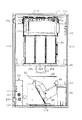
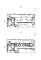
手段8.手段2乃至5のいずれかにおいて、前記遊技機前面体には、前記絵柄表示装置における絵柄の可変表示を視認可能とする窓部(表示窓31)よりも遊技機前方へ突出させて操作部(操作部70)を設け、当該操作部に前記受入手段、前記始動操作手段、及び前記停止操作手段を配設し、
前記操作部の背面側には、前記遊技機前面体の背面側から見て凹むようにして設けられ、前記受入手段、前記始動操作手段、又は前記停止操作手段のうち少なくとも一つを収容する収容凹部(収容空間200)を形成し、
前記中継基板は、前記受入手段、前記始動操作手段、又は前記停止操作手段のうち前記収容凹部に収容される収容対象からの検出信号を前記入力手段に対して中継し、
さらに、前記収容対象と対峙した位置にて前記収容凹部の背面側開放部(背面側開放部201)を塞ぎ、且つ前記入力側信号線が接続された板面が前記収容凹部側を向くようにして前記中継基板を取り付けたことを特徴とする遊技機。
On the back side of the operation unit, a recess is provided so as to be recessed when viewed from the back side of the front body of the gaming machine, and houses at least one of the receiving means, the start operation means, or the stop operation means. A storage space 200),
The relay board relays a detection signal from a receiving object stored in the receiving recess of the receiving means, the start operation means, or the stop operation means to the input means,
Furthermore, the back side open part (back side open part 201) of the accommodation recess is closed at a position facing the accommodation object, and the plate surface to which the input signal line is connected faces the accommodation recess side. A game machine having the relay board attached thereto.
手段8によれば、受入手段、始動操作手段、及び停止操作手段が遊技機前方へ突出させて設けられた操作部に配設されているので、遊技者にとっては遊技を行う上での操作を行い易くなる。この場合に、操作部の背面側には収容凹部が形成されており、収容凹部には受入手段、始動操作手段、又は停止操作手段のうち少なくとも1つが収容されている。また、中継基板ではその収容対象からの検出信号を中継する。
According to the
かかる構成において、中継基板は収容対象と対峙した位置にて収容凹部の背面側開放部を塞ぐようにして取り付けられている。これにより、入力側信号線の収容対象側における接続箇所が中継基板によって隠される。また、中継基板における入力側信号線が接続された板面が収容凹部側を向くため、遊技機前面体を遊技機本体に対して開いたとしても中継基板における入力側信号線の接続箇所が露出することはない。 In such a configuration, the relay board is attached so as to close the open portion on the back side of the housing recess at a position facing the housing object. Thereby, the connection location on the accommodation target side of the input side signal line is hidden by the relay board. In addition, since the plate surface to which the input side signal line on the relay board is connected faces the housing recess side, the connection part of the input side signal line on the relay board is exposed even if the gaming machine front body is opened with respect to the gaming machine body. Never do.
以上より、信号出力装置を用いた不正行為時における入力側信号線の取り外しが困難なものとなる。そして、信号出力装置を取り付けるために接続ユニットを外すと電源が情報記憶手段に供給されなくなる。よって、信号出力装置を制御基板装置に接続し、不正に特別遊技状態への移行当選や特別遊技状態への移行を行わせる行為を確実に抑制することができる。また、本構成では、操作部の構成を有効利用しつつ、上記効果を得ることができる。 As described above, it is difficult to remove the input-side signal line at the time of fraud using the signal output device. When the connection unit is removed to attach the signal output device, power is not supplied to the information storage means. Therefore, it is possible to reliably suppress the act of connecting the signal output device to the control board device and illegally making a transition to the special gaming state or shifting to the special gaming state. Moreover, in this structure, the said effect can be acquired, utilizing the structure of an operation part effectively.
手段9.手段1乃至8のいずれかにおいて、前記中継部は、前記媒体検出信号、前記始動検出信号、又は前記停止検出信号のうち2以上の検出信号を中継し、
前記接続ユニットは、その中継部にて中継される全ての検出信号の出力側信号線を備え、
前記抑制構造は、前記中継部における前記各出力側信号線に対応した入力側信号線の全ての取り外しを抑制することを特徴とする遊技機。
The connection unit includes output signal lines of all detection signals relayed by the relay unit,
The gaming machine is characterized in that the suppression structure suppresses all removal of the input-side signal lines corresponding to the output-side signal lines in the relay unit.
手段9によれば、接続ユニットには媒体検出信号、始動検出信号、及び停止検出信号のうちの2以上の検出信号に対応した出力側信号線が設けられており、さらに中継部における、各出力側信号線に対応した入力側信号線の全ての取り外しが抑制されている。かかる構成の場合、各入力側信号線を外してその代わりに信号出力装置を接続しようとしてもそれが困難なものとなる。そして、信号出力装置を取り付けるために接続ユニットを外すと電源が情報記憶手段に供給されなくなる。
According to the
手段10.手段1乃至9のいずれかにおいて、外部電源から供給される電源が遮断された場合に前記情報記憶手段に記憶された遊技情報が保持されるように当該情報記憶手段に遮断時用電源を供給する遮断時用電源手段(バックアップ用コンデンサ161c、バックアップ用コンデンサ209)を備え、
当該遮断時用電源手段の電源を、前記出力側電源線を介して供給するようにしたことを特徴とする遊技機。
A gaming machine characterized in that the power supply of the power supply means for shutoff is supplied through the output-side power supply line.
手段10によれば、遮断時用電源手段が設けられていることにより、外部電源から供給される電源が遮断されたとしてもその前に情報記憶手段に記憶されていた遊技情報は保持される。この場合に、接続ユニットを外すと、情報記憶手段への遮断時用電源の供給が停止され、情報記憶手段に記憶されていた遊技情報は消去される。よって、遊技機の電源が遮断されている状態において電源の供給が可能な信号出力装置を接続し、情報記憶手段に特定役当選の情報や遊技状態情報を記憶させたとしても、信号出力装置を外して正規の信号線に付け替える際に情報記憶手段への電源の供給が停止され、記憶させた特定役当選の情報や遊技状態情報は消去される。よって、かかる行為を抑制することができる。
According to the
手段11.絵柄を可変表示する絵柄表示装置(リールユニット41)と、
遊技媒体を受け入れる受入手段(メダル投入口75、セレクタ84)と、
前記絵柄の可変表示を開始させるべく操作される始動操作手段(スタートレバー71)と、
前記絵柄の可変表示を停止させるべく操作される停止操作手段(ストップスイッチ72〜74)と、
前記受入手段からの媒体検出信号、前記始動操作手段からの始動検出信号、及び前記停止操作手段からの停止検出信号を入力し、前記媒体検出信号の入力及び前記始動検出信号の入力に基づいて前記絵柄の可変表示を開始させるとともに、前記停止検出信号の入力に基づいて前記絵柄の可変表示を停止させる制御基板装置(主制御装置131)と、
当該制御基板装置に対して前記絵柄表示装置の開始及び停止制御を行う上で必要な電源を供給する電源装置(電源装置161)と
を備え、
前記制御基板装置は前記絵柄の可変表示の停止後における停止絵柄に応じて特典を付与するよう構成した遊技機において、
前記開始及び停止制御を行う上で前記制御基板装置が入力する検出信号のうち少なくとも一つを当該制御基板装置に対して中継するとともに、前記制御基板装置に対して電源を中継する中継部(中継基板165、停止操作基板206)を備え、
当該中継部からの出力側信号線及び出力側電源線(電源線ELN3、電源線ELN5)を、中継部側のコネクタ(コネクタCN9)と制御基板装置側のコネクタ(コネクタCN10)とに繋げることで接続ユニット(ハーネスH、ハーネスH2)として構成し、
前記中継部に接続された入力側信号線(信号線LN2,LN4、信号線LN5〜LN7)の当該中継部からの取り外しを抑制する抑制構造を有することを特徴とする遊技機。
Receiving means for receiving game media (
Start operation means (start lever 71) operated to start variable display of the pattern;
Stop operation means (stop switches 72 to 74) operated to stop the variable display of the pattern;
The medium detection signal from the receiving means, the start detection signal from the start operation means, and the stop detection signal from the stop operation means are input, and based on the input of the medium detection signal and the input of the start detection signal, A control board device (main control device 131) that starts variable display of a pattern and stops variable display of the pattern based on the input of the stop detection signal;
A power supply device (power supply device 161) that supplies power necessary for performing start and stop control of the pattern display device to the control board device;
In the gaming machine configured to give a privilege according to the stop pattern after the variable display of the pattern is stopped, the control board device,
In performing the start and stop control, at least one of detection signals input by the control board device is relayed to the control board device, and a relay unit (relay) relays power to the control board device.
By connecting the output side signal line and the output side power supply line (power supply line ELN3, power supply line ELN5) from the relay unit to the connector on the relay unit side (connector CN9) and the connector on the control board device side (connector CN10). Configure as a connection unit (harness H, harness H2),
A gaming machine having a suppression structure that suppresses removal of input-side signal lines (signal lines LN2, LN4, signal lines LN5 to LN7) connected to the relay unit from the relay unit.
手段11の遊技機では、受入手段により予め定められた数の遊技媒体が受け入れられ、且つ始動操作手段が操作されることにより、絵柄表示装置における絵柄の可変表示を開始する。また、停止操作手段が操作されることで絵柄の可変表示を停止する。そして、停止絵柄に応じて特典が付与される。
In the gaming machine of
この場合に、中継部が設けられており、制御基板装置が入力する検出信号のうち少なくとも一つが中継されるとともに、制御基板装置に対する電源が中継される。また、中継部からの出力側信号線及び出力側電源線は、接続ユニットとして構成されている。これにより、信号出力装置から制御基板装置に対して不正信号を出力するために接続ユニットを外すと、電源が制御基板装置に供給されなくなる。特に、本手段における構成では、抑制構造を有しており、入力側信号線の中継部からの取り外しが抑制されている。つまり、入力側信号線を外してその代わりに信号出力装置を接続しようとしてもそれが容易に行えないようになっている。 In this case, a relay unit is provided, and at least one of detection signals input by the control board device is relayed, and power to the control board device is relayed. The output signal line and the output power line from the relay unit are configured as a connection unit. Accordingly, when the connection unit is removed in order to output an illegal signal from the signal output device to the control board device, power is not supplied to the control board device. In particular, the configuration of this means has a suppression structure, and the removal of the input side signal line from the relay portion is suppressed. That is, even if an input signal line is disconnected and a signal output device is connected instead, it cannot be easily performed.
以上の構成により、信号出力装置を制御基板装置に接続し、遊技媒体の投入や各種操作手段の操作を実際に行うことなく遊技を行おうとしたとしても、電源が制御基板装置に供給されなくなり、遊技を行うことができなくなる。よって、信号出力装置を接続し、遊技媒体の投入や各種操作手段の操作を実際に行うことなく遊技を行おうとする行為を抑制することができる。 With the above configuration, even if the signal output device is connected to the control board device and a game is attempted without actually inserting the game medium or operating various operation means, power is not supplied to the control board device. You will not be able to play games. Therefore, it is possible to suppress the act of playing a game without connecting a signal output device and actually performing the insertion of the game medium or the operation of various operation means.
なお、中継部にて中継する検出信号を、媒体検出信号、始動検出信号、及び停止検出信号のうち少なくとも一つとする構成が考えられる。但し、これら各検出信号以外の検出信号に対応した不正信号を信号出力装置から出力することで上記不正行為が行われる場合には、中継部にてその検出信号を中継するようにしてもよい。 In addition, the structure which makes the detection signal relayed in a relay part at least one among a medium detection signal, a starting detection signal, and a stop detection signal can be considered. However, when the fraudulent action is performed by outputting a fraud signal corresponding to a detection signal other than the detection signals from the signal output device, the relay unit may relay the detection signal.
また、本手段11に対して上記手段2乃至10のいずれかを適用することで各手段の効果を奏することができる。
Further, by applying any one of the above-described
手段12.絵柄を可変表示する絵柄表示装置(リールユニット41)と、
遊技媒体を受け入れる受入手段(メダル投入口75、セレクタ84)と、
前記絵柄の可変表示を開始させるべく操作される始動操作手段(スタートレバー71)と、
前記絵柄の可変表示を停止させるべく操作される停止操作手段(ストップスイッチ72〜74)と、
前記絵柄の可変表示を制御する制御基板装置(主制御装置131)と、
当該制御基板装置に電源を供給する電源装置(電源装置161)と
を備え、
前記制御基板装置は、
前記受入手段からの媒体検出信号、前記始動操作手段からの始動検出信号、及び前記停止操作手段からの停止検出信号を含めた各検出信号を入力する入力手段(コネクタCN28)と、
前記媒体検出信号の入力、及び前記始動検出信号の入力に基づいて、役の抽選を行う抽選手段(主制御装置131の抽選処理)と、
その抽選結果を含めた遊技情報を記憶するとともに、電源が供給されている間はその記憶した情報の保持を可能とする情報記憶手段(RAM153)と、
前記媒体検出信号の入力、及び前記始動検出信号の入力に基づいて、前記絵柄の可変表示を開始させるとともに、前記停止検出信号の入力に基づいて、前記絵柄の可変表示を停止させる可変表示制御手段(主制御装置131のリール制御処理)と、
前記遊技情報が特定役当選の情報であって、停止後の停止絵柄が特定絵柄である場合に、遊技状態を遊技者に有利な特別遊技状態に移行させる状態移行手段(主制御装置131のボーナスゲーム処理)とを備え、
前記情報記憶手段は、前記特定役当選の情報を記憶した場合、停止後の停止絵柄が前記特定絵柄となることで当該特定役当選の情報を消去し、遊技状態が特別遊技状態である場合、遊技状態情報を記憶保持する構成とした遊技機において、
前記可変表示手段による前記開始及び停止制御を行う上で前記入力手段が入力する検出信号のうち少なくとも一つを当該入力手段に対して中継する中継部(中継基板165、停止操作基板206)を備え、
当該中継部からの出力側信号線(ハーネスH3)と、前記情報記憶手段に前記電源を供給する電源線(電源線ELN6)とを、前記制御基板装置側に対してまとめて接続するためのコネクタ(コネクタCN26)を設けるとともに、
入力側信号線(信号線LN2,LN4)及び前記出力側信号線の前記中継部からの取り外しを抑制する抑制構造を有することを特徴とする遊技機。
Receiving means for receiving game media (
Start operation means (start lever 71) operated to start variable display of the pattern;
Stop operation means (stop switches 72 to 74) operated to stop the variable display of the pattern;
A control board device (main control device 131) for controlling the variable display of the pattern;
A power supply device (power supply device 161) for supplying power to the control board device,
The control board device includes:
Input means (connector CN28) for inputting detection signals including a medium detection signal from the receiving means, a start detection signal from the start operation means, and a stop detection signal from the stop operation means;
Lottery means (lottery process of the main control device 131) for performing the lottery of the combination based on the input of the medium detection signal and the input of the start detection signal;
Information storage means (RAM 153) for storing game information including the lottery result and holding the stored information while power is supplied;
Variable display control means for starting the variable display of the picture based on the input of the medium detection signal and the input of the start detection signal and stopping the variable display of the picture based on the input of the stop detection signal (Reel control processing of the main controller 131);
State transition means (bonus of the main control device 131) for transitioning the gaming state to a special gaming state advantageous to the player when the gaming information is information on winning the specific role and the stopped pattern after the stop is the specific pattern. Game processing),
When the information storing means stores the information on the specific combination winning, the information on the specific combination winning is deleted by the stop pattern after the stop being the specific pattern, and the gaming state is the special gaming state, In a gaming machine configured to store and hold gaming state information,
A relay unit (
A connector for collectively connecting the output side signal line (harness H3) from the relay section and the power supply line (power supply line ELN6) for supplying the power to the information storage means to the control board device side (Connector CN26) is provided,
A gaming machine having a suppression structure that suppresses removal of an input side signal line (signal lines LN2, LN4) and the output side signal line from the relay unit.
手段12の遊技機では、受入手段により予め定められた数の遊技媒体が受け入れられ、且つ始動操作手段が操作されることにより、役の抽選が行われるとともに、絵柄表示装置における絵柄の可変表示が開始される。この場合に、役の抽選結果は情報記憶手段に記憶される。また、停止操作手段が操作されることで絵柄の可変表示が停止される。そして、情報記憶手段に特定役当選の情報が記憶された状態にて特定絵柄(なお、この特定絵柄に代えて、特定絵柄の組合せとしてもよい)が停止することで、遊技状態が特別遊技状態に移行する。
In the gaming machine of the
この場合に、中継部が設けられており、入力手段が入力する検出信号のうち少なくとも一つが中継される。また、コネクタが設けられており、当該コネクタにより出力側信号線及び電源線が制御基板装置側に対してまとめて接続される。これにより、信号出力装置から制御基板装置に対して不正信号を出力するためにコネクタを外すと、電源が情報記憶手段に供給されなくなる。特に、本手段における構成では、抑制構造を有しており、中継部からの入力側信号線の取り外しが抑制されている。つまり、コネクタを外すことなく、入力側信号線や出力側信号線を外してその代わりに信号出力装置を接続しようとしてもそれが容易に行えないようになっている。 In this case, a relay unit is provided, and at least one of the detection signals input by the input unit is relayed. In addition, a connector is provided, and the output side signal line and the power supply line are collectively connected to the control board device side by the connector. Thus, when the connector is removed in order to output an illegal signal from the signal output device to the control board device, power is not supplied to the information storage means. In particular, the configuration of this means has a suppression structure, and the removal of the input-side signal line from the relay unit is suppressed. In other words, without removing the connector, even if the input side signal line or the output side signal line is disconnected and the signal output device is connected instead, it cannot be easily performed.
以上の構成により、信号出力装置を接続し、情報記憶手段に特定役当選の情報や遊技状態情報を記憶させたとしても、信号出力装置を外して正規の信号線に付け替える際に情報記憶手段への電源の供給が停止され、記憶させた特定役当選の情報や遊技状態情報は消去される。よって、信号出力装置を接続し、不正に特別遊技状態への移行当選や特別遊技状態への移行を行わせる行為を抑制することができる。特に、本構成によれば、信号出力装置の接続に際して情報記憶手段へ電源を供給する電源線が取り外されるようにしたため、仮に、電源供給の可能な信号出力装置が使用されたとしても、それに基づく上記不正行為を抑制することができる。 With the above configuration, even when the signal output device is connected and the information storage means stores the information on the specific role winning and the game state information, when the signal output device is removed and replaced with the regular signal line, the information storage means The supply of the power is stopped, and the stored information on the specific winning combination and the game state information are erased. Therefore, it is possible to suppress the act of connecting the signal output device and illegally making a transition to the special game state or making a transition to the special game state. In particular, according to this configuration, since the power supply line for supplying power to the information storage means is removed when the signal output device is connected, even if a signal output device capable of supplying power is used, it is based on it. The cheating can be suppressed.
なお、中継部にて中継する検出信号を、媒体検出信号、始動検出信号、及び停止検出信号のうち少なくとも一つとする構成が考えられる。但し、これら各検出信号以外の検出信号に対応した不正信号を信号出力装置から出力することで上記不正行為が行われる場合には、中継部にてその検出信号を中継するようにしてもよい。 In addition, the structure which makes the detection signal relayed in a relay part at least one among a medium detection signal, a starting detection signal, and a stop detection signal can be considered. However, when the fraudulent action is performed by outputting a fraud signal corresponding to a detection signal other than the detection signals from the signal output device, the relay unit may relay the detection signal.
手段13.絵柄を可変表示する絵柄表示装置(リールユニット41)と、
遊技媒体を受け入れる受入手段(メダル投入口75、セレクタ84)と、
前記絵柄の可変表示を開始させるべく操作される始動操作手段(スタートレバー71)と、
前記絵柄の可変表示を停止させるべく操作される停止操作手段(ストップスイッチ72〜74)と、
前記受入手段からの媒体検出信号、前記始動操作手段からの始動検出信号、及び前記停止操作手段からの停止検出信号を入力し、前記媒体検出信号の入力及び前記始動検出信号の入力に基づいて前記絵柄の可変表示を開始させるとともに、前記停止検出信号の入力に基づいて前記絵柄の可変表示を停止させる制御基板装置(主制御装置131)と、
当該制御基板装置に対して前記絵柄表示装置の開始及び停止制御を行う上で必要な電源を供給する電源装置(電源装置161)と
を備え、
前記制御基板装置は、前記絵柄の可変表示の停止後における停止絵柄に応じて特典を付与する遊技機において、
前記開始及び停止制御を行う上で前記制御基板装置が入力する検出信号のうち少なくとも一つを当該制御基板装置に対して中継する中継部(中継基板165、停止操作基板206)を備え、
当該中継部からの出力側信号線(ハーネスH3)と、前記制御基板装置に前記電源を供給する電源線(電源線ELN6)とを、前記制御基板装置側に対してまとめて接続するためのコネクタ(コネクタCN26)を設けるとともに、
入力側信号線(信号線LN2,LN4)及び前記出力側信号線の前記中継部からの取り外しを抑制する抑制構造を有することを特徴とする遊技機。
Receiving means for receiving game media (
Start operation means (start lever 71) operated to start variable display of the pattern;
Stop operation means (stop switches 72 to 74) operated to stop the variable display of the pattern;
The medium detection signal from the receiving means, the start detection signal from the start operation means, and the stop detection signal from the stop operation means are input, and based on the input of the medium detection signal and the input of the start detection signal, A control board device (main control device 131) that starts variable display of a pattern and stops variable display of the pattern based on the input of the stop detection signal;
A power supply device (power supply device 161) that supplies power necessary for performing start and stop control of the pattern display device to the control board device;
In the gaming machine that gives a privilege according to the stop picture after the variable display of the picture is stopped, the control board device,
A relay unit (
A connector for collectively connecting the output side signal line (harness H3) from the relay unit and the power supply line (power supply line ELN6) for supplying the power to the control board device to the control board device side (Connector CN26) is provided,
A gaming machine having a suppression structure that suppresses removal of an input side signal line (signal lines LN2, LN4) and the output side signal line from the relay unit.
手段13の遊技機では、受入手段により予め定められた数の遊技媒体が受け入れられ、且つ始動操作手段が操作されることにより、絵柄表示装置における絵柄の可変表示を開始する。また、停止操作手段が操作されることで絵柄の可変表示を停止する。そして、停止絵柄に応じて特典が付与される。
In the gaming machine of the
この場合に、中継部が設けられており、制御基板装置が入力する検出信号のうち少なくとも一つが中継される。また、コネクタが設けられており、当該コネクタにより出力側信号線及び電源線が制御基板装置側に対してまとめて接続される。これにより、信号出力装置から制御基板装置に対して不正信号を出力するためにコネクタを外すと、電源が制御基板装置に供給されなくなる。特に、本手段における構成では抑制構造を有しており、中継部からの入力側信号線の取り外しが抑制されている。つまり、コネクタを外すことなく、入力側信号線や出力側信号線を外してその代わりに信号出力装置を接続しようとしてもそれが容易に行えないようになっている。 In this case, a relay unit is provided, and at least one of the detection signals input by the control board device is relayed. In addition, a connector is provided, and the output side signal line and the power supply line are collectively connected to the control board device side by the connector. Accordingly, when the connector is removed in order to output an illegal signal from the signal output device to the control board device, power is not supplied to the control board device. In particular, the configuration of this means has a suppression structure, and the removal of the input-side signal line from the relay unit is suppressed. In other words, without removing the connector, even if the input side signal line or the output side signal line is disconnected and the signal output device is connected instead, it cannot be easily performed.
以上の構成により、信号出力装置を接続し、遊技媒体の投入や各種操作手段の操作を実際に行うことなく遊技を行おうとしたとしても、電源が制御基板装置に供給されなくなり、遊技を行うことができなくなる。よって、信号出力装置を制御基板装置に接続し、遊技媒体の投入や各種操作手段の操作を実際に行うことなく遊技を行おうとする行為を抑制することができる。 With the above configuration, even if a signal output device is connected and a game is attempted without actually inserting a game medium or operating various operation means, power is not supplied to the control board device and the game is performed. Can not be. Therefore, it is possible to suppress an act of playing a game without connecting the signal output device to the control board device and actually performing the insertion of the game medium or the operation of various operation means.
なお、中継部にて中継する検出信号を、媒体検出信号、始動検出信号、及び停止検出信号のうち少なくとも一つとする構成が考えられる。但し、これら各検出信号以外の検出信号に対応した不正信号を信号出力装置から出力することで上記不正行為が行われる場合には、中継部にてその検出信号を中継するようにしてもよい。 In addition, the structure which makes the detection signal relayed in a relay part at least one among a medium detection signal, a starting detection signal, and a stop detection signal can be considered. However, when the fraudulent action is performed by outputting a fraud signal corresponding to a detection signal other than the detection signals from the signal output device, the relay unit may relay the detection signal.
手段14.絵柄を可変表示する絵柄表示装置(リールユニット41)と、
遊技媒体を受け入れる受入手段(メダル投入口75)と、
その受け入れた遊技媒体を検出する検出手段(投入メダル検出センサ84b)と、
前記絵柄の可変表示を開始させるべく操作される始動操作手段(スタートレバー71)と、
前記絵柄の可変表示を停止させるべく操作される停止操作手段(ストップスイッチ72〜74)と、
前記絵柄の可変表示を制御する制御基板装置(主制御装置131)と、
当該制御基板装置に電源を供給する電源装置(電源装置161)と
を備え、
前記制御基板装置は、
前記検出手段からの媒体検出信号、前記始動操作手段からの始動検出信号、及び前記停止操作手段からの停止検出信号を含めた各種信号を入力する入力手段(コネクタCN9)と、
前記媒体検出信号の入力、及び前記始動検出信号の入力に基づいて、役の抽選を行う抽選手段(主制御装置131の抽選処理)と、
その抽選結果を含めた遊技情報を記憶するとともに、電源が供給されている間はその記憶した情報の保持を可能とする情報記憶手段(RAM153)と、
前記媒体検出信号の入力、及び前記始動検出信号の入力に基づいて、前記絵柄の可変表示を開始させるとともに、前記停止検出信号の入力に基づいて、前記絵柄の可変表示を停止させる可変表示制御手段(主制御装置131のリール制御処理)と、
前記遊技情報が特定役当選の情報であって、停止後の停止絵柄が特定絵柄である場合に、遊技状態を遊技者に有利な特別遊技状態に移行させる状態移行手段(主制御装置131のボーナスゲーム処理)とを備え、
前記情報記憶手段は、前記特定役当選の情報を記憶した場合、停止後の停止絵柄が前記特定絵柄となることで当該特定役当選の情報を消去するとともに、遊技状態が特別遊技状態である場合、遊技状態情報を記憶保持する構成とした遊技機において、
前記可変表示手段による前記開始及び停止制御を行う上で前記入力手段が入力する検出信号のうち少なくとも一つを当該入力手段に対して中継する中継部(中継基板165、停止操作基板206)を備え、
前記中継部と前記制御基板装置との間に電気経路を設けるとともに、当該電気経路の遮断中には前記情報記憶手段へ電源を供給しない構成とし、
前記電気経路を形成する電気配線(電源線ELN3,ELN5、接続用確認線LLN1)、及び前記中継部からの出力側信号線を、中継部側のコネクタ(コネクタCN9)と制御基板装置側のコネクタ(コネクタCN10)とにまとめて繋げることで接続ユニット(ハーネスH、ハーネスH2)として構成し、
前記中継部に接続された入力側信号線(信号線LN2,LN4、信号線LN5〜LN7)の当該中継部からの取り外しを抑制する抑制構造を有することを特徴とする遊技機。
Receiving means (medal slot 75) for receiving game media;
Detecting means (inserted medal detection sensor 84b) for detecting the received game medium;
Start operation means (start lever 71) operated to start variable display of the pattern;
Stop operation means (stop switches 72 to 74) operated to stop the variable display of the pattern;
A control board device (main control device 131) for controlling the variable display of the pattern;
A power supply device (power supply device 161) for supplying power to the control board device,
The control board device includes:
Input means (connector CN9) for inputting various signals including a medium detection signal from the detection means, a start detection signal from the start operation means, and a stop detection signal from the stop operation means;
Lottery means (lottery process of the main control device 131) for performing the lottery of the combination based on the input of the medium detection signal and the input of the start detection signal;
Information storage means (RAM 153) for storing game information including the lottery result and holding the stored information while power is supplied;
Variable display control means for starting the variable display of the picture based on the input of the medium detection signal and the input of the start detection signal and stopping the variable display of the picture based on the input of the stop detection signal (Reel control processing of the main controller 131);
State transition means (bonus of the main control device 131) for transitioning the gaming state to a special gaming state advantageous to the player when the gaming information is information on winning the specific role and the stopped pattern after the stop is the specific pattern. Game processing),
When the information storing means stores the information on the specific combination winning, when the stop pattern after the stop becomes the specific pattern, the specific winning combination information is erased and the gaming state is a special gaming state. In a gaming machine configured to store and hold gaming state information,
A relay unit (
An electrical path is provided between the relay unit and the control board device, and power is not supplied to the information storage unit while the electrical path is interrupted.
The electrical wiring (power supply lines ELN3, ELN5, connection confirmation line LLN1) forming the electrical path, and the output side signal line from the relay section are connected to the relay section side connector (connector CN9) and the control board device side connector. (Connector CN10) is connected together and configured as a connection unit (harness H, harness H2),
A gaming machine having a suppression structure that suppresses removal of input-side signal lines (signal lines LN2, LN4, signal lines LN5 to LN7) connected to the relay unit from the relay unit.
手段14の遊技機では、受入手段により予め定められた数の遊技媒体が受け入れられ、且つ始動操作手段が操作されることにより、役の抽選が行われるとともに、絵柄表示装置における絵柄の可変表示が開始される。この場合に、役の抽選結果は情報記憶手段に記憶される。また、停止操作手段が操作されることで絵柄の可変表示が停止する。そして、情報記憶手段に特定役当選の情報が記憶された状態にて特定絵柄(なお、この特定絵柄に代えて、特定絵柄の組合せとしてもよい)が停止することで、遊技状態が特別遊技状態に移行する。
In the gaming machine of the
この場合に、入力手段が入力する検出信号のうち少なくとも一つが中継部にて中継され、中継部と制御基板装置との間には電気経路が設けられている。また、中継部からの出力側信号線と、電気経路を形成する電気配線とは接続ユニットとして構成されている。したがって、不正な信号を出力する信号出力装置を制御基板装置に接続するために接続ユニットを外すと、電気配線が外されて電気経路が遮断される。ここで、電気経路の遮断中には電源が情報記憶手段に供給されないように構成されているため、接続ユニットを外すと、電源が情報記憶手段に供給されなくなる。特に、本手段における構成では、抑制構造を有しており、入力側信号線の中継部からの取り外しが抑制されている。つまり、入力側信号線を外してその代わりに信号出力装置を接続しようとしてもそれが容易に行えないようになっている。 In this case, at least one of the detection signals input by the input means is relayed by the relay unit, and an electrical path is provided between the relay unit and the control board device. Further, the output side signal line from the relay unit and the electric wiring forming the electric path are configured as a connection unit. Therefore, when the connection unit is removed in order to connect the signal output device that outputs an illegal signal to the control board device, the electrical wiring is removed and the electrical path is interrupted. Here, since the power is not supplied to the information storage means while the electric path is interrupted, the power is not supplied to the information storage means when the connection unit is removed. In particular, the configuration of this means has a suppression structure, and the removal of the input side signal line from the relay portion is suppressed. That is, even if an input signal line is disconnected and a signal output device is connected instead, it cannot be easily performed.
以上の構成により、信号出力装置を接続し、情報記憶手段に特定役当選の情報や遊技状態情報を記憶させたとしても、信号出力装置を外して正規の信号線に付け替える際に情報記憶手段への電源の供給が停止され、記憶させた特定役当選の情報や遊技状態情報が消去される。よって、信号出力装置を接続し、不正に特別遊技状態への移行当選や特別遊技状態への移行を行わせる行為を抑制することができる。特に、本構成によれば、信号出力装置の接続に際して電気配線が取り外されるようにしたため、仮に、電源供給の可能な信号出力装置が使用されたとしても、それに基づく上記不正行為を抑制することができる。 With the above configuration, even when the signal output device is connected and the information storage means stores the information on the specific role winning and the game state information, when the signal output device is removed and replaced with the regular signal line, the information storage means The supply of power is stopped, and the stored information on the winning combination and gaming state information is erased. Therefore, it is possible to suppress the act of connecting the signal output device and illegally making a transition to the special game state or making a transition to the special game state. In particular, according to this configuration, since the electric wiring is removed when the signal output device is connected, even if a signal output device capable of supplying power is used, the above-mentioned fraudulent act can be suppressed. it can.
なお、中継部にて中継する検出信号を、媒体検出信号、始動検出信号、及び停止検出信号のうち少なくとも一つとする構成が考えられる。但し、これら各検出信号以外の検出信号に対応した不正信号を信号出力装置から出力することで上記不正行為が行われる場合には、中継部にてその検出信号を中継するようにしてもよい。 In addition, the structure which makes the detection signal relayed in a relay part at least one among a medium detection signal, a starting detection signal, and a stop detection signal can be considered. However, when the fraudulent action is performed by outputting a fraud signal corresponding to a detection signal other than the detection signals from the signal output device, the relay unit may relay the detection signal.
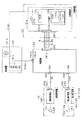
手段15.手段14において、前記制御基板装置に対して前記電気経路を介して接続情報信号を出力する接続情報信号出力手段(接続確認用信号線LLN1の接地)と、
前記電気配線として前記接続情報信号を伝達する接続情報信号線(接続確認用信号線LLN1)と、
前記接続情報信号が伝達されている場合のみ前記電源装置から前記情報記憶手段へ電源を供給する電源制御回路(切替回路212)と、
を備えたことを特徴とする遊技機。
A connection information signal line (connection confirmation signal line LLN1) that transmits the connection information signal as the electrical wiring;
A power supply control circuit (switching circuit 212) for supplying power from the power supply device to the information storage means only when the connection information signal is transmitted;
A gaming machine characterized by comprising:
手段15の遊技機では、接続情報信号線を介して接続情報信号が伝達されている場合のみ、電源制御回路によって情報記憶手段に電源が供給される。よって、不正な信号を出力する信号出力装置を制御基板装置に接続するために、接続ユニットを中継部や制御基板装置から外すと、出力側信号線とともに接続情報信号線が外れて接続情報信号が伝達されなくなり、その結果電源制御回路によって情報記憶手段への電源供給が停止される。特に、本構成によれば、信号出力装置の接続に際し接続情報信号が伝達されなくなると情報記憶手段への電源供給が停止するようにしたため、仮に、接続用信号を擬似出力することが可能な信号出力装置が使用されたとしても、それに基づく上記不正行為を抑制することができる。
In the gaming machine of
手段16.手段15において、前記接続情報信号出力手段は、前記接続情報信号線をグランドに接地してなることを特徴とする遊技機。
手段16によれば、接続情報信号線がグランドに接地されることにより、接続情報信号として基準電位が出力される。この場合、接続情報信号を生成する生成回路等を設ける必要がなく、接続情報信号出力手段の構成を簡素にすることができる。
According to the
手段17.手段15又は16において、前記電源制御回路は、前記電源装置から前記情報記憶手段に電源を供給する経路に接続されたスイッチング素子(MOSFET212a)を備え、
前記接続情報信号が伝達されていない場合には前記スイッチング素子が遮断状態となるように構成したことを特徴とする遊技機。
A gaming machine, wherein the switching element is cut off when the connection information signal is not transmitted.
手段17によれば、接続情報信号が伝達されていない場合には、スイッチング素子が遮断状態となる。このため、信号出力装置を制御基板装置に接続するために、接続ユニットを中継部や制御基板装置から外すと、それに伴って接続情報信号が伝達されなくなる。そして、情報記憶手段に電源を供給する経路が遮断され、その結果電源装置から情報記憶手段へ電源が供給されなくなる。
According to the
手段18.手段15乃至17のいずれかにおいて、前記電源制御回路を、前記制御基板装置に搭載したことを特徴とする遊技機。
手段18によれば、電源制御回路を制御基板装置に搭載することにより、電源制御回路と情報記憶手段とを結ぶ電源線(ハーネス)が不要になる。また、電源制御回路を他の電子部品と共に制御基板装置に集約することが可能であるため、電源供給系の構成の簡素化を図ることができる。
According to the
手段19.手段15乃至18のいずれかにおいて、外部電源から供給される電源が遮断された場合に前記情報記憶手段に記憶された遊技情報が保持されるように当該情報記憶手段に遮断時用電源を供給する遮断時用電源手段(バックアップ用電源生成回路211)を備え、
前記電源制御回路は、前記電源装置に加えて前記遮断時用電源手段からの電源を、前記接続情報信号が伝達されている場合のみ前記情報記憶手段へ供給することを特徴とする遊技機。
The gaming machine according to
手段19によれば、遮断時用電源手段が設けられていることにより、外部電源から供給される電源が遮断されたとしてもその前に情報記憶手段に記憶されていた遊技情報は保持される。ここで、遮断時用電源手段からの電源も、電源制御回路によって接続情報信号が伝達されている場合のみ情報記憶手段へ供給されるようになっている。
According to the
この場合に、接続ユニットを中継部や制御基板装置から外すと、接続情報信号が伝達されなくなるため、電源制御回路によって情報記憶手段への遮断時用電源の供給が行われなくなり、情報記憶手段に記憶されていた遊技情報は消去される。よって、遊技機の電源が遮断されている状態において接続情報信号を擬似可能な信号出力装置を制御基板装置に接続し、情報記憶手段に特定役当選の情報や遊技状態情報を記憶させたとしても、信号出力装置を外して正規の信号線に付け替える際に情報記憶手段への電源の供給が停止され、記憶させた特定役当選の情報や遊技状態情報は消去される。よって、かかる行為を抑制することができる。 In this case, if the connection unit is removed from the relay unit or the control board device, the connection information signal is not transmitted, so that the power supply control circuit does not supply the power for shutting off to the information storage means. The stored game information is deleted. Therefore, even if the signal output device that can simulate the connection information signal is connected to the control board device in a state where the power supply of the gaming machine is cut off, and the information storage means stores the information on the winning of the specific role and the game state information. When the signal output device is removed and replaced with a regular signal line, the supply of power to the information storage means is stopped, and the stored specific combination winning information and gaming state information are erased. Therefore, this act can be suppressed.
手段20.手段19において、前記遮断時用電源手段を、前記制御基板装置に搭載したことを特徴とする遊技機。
手段20によれば、遮断時用電源手段を制御基板装置に搭載することにより、遮断時用電源手段と情報記憶手段とを結ぶ電源線(ハーネス)が不要になる。また、遮断時用電源手段を他の電子部品と共に制御基板装置に集約することが可能であるため、電源供給系の構成の簡素化を図ることができる。
According to the
手段21.手段14乃至20のいずれかにおいて、前記中継部は中継基板であり、
前記抑制構造として、前記中継基板における前記入力側信号線が接続される板面(手前側板面165a、手前側板面206a)を、遊技機前面部を構成する遊技機前面体(前面扉12)の裏側壁面、又は当該遊技機前面体が取り付けられる遊技機本体(筐体11)の内壁面と対峙させたことを特徴とする遊技機。
As the restraining structure, the board surface (the front
手段21によれば、中継基板における入力側信号線が接続された板面が遊技機前面体の裏側壁面、又は遊技機本体の内壁面と対峙しているため、中継基板からの入力側信号線の取り外しが抑制される。よって、入力側信号線を取り外してその代わりに信号出力装置を接続しようとしてもそれが容易に行えず、接続ユニットを外すと上記のとおり電源が情報記憶手段に供給されなくなる。
According to the
手段22.手段21において、前記中継基板を、前記遊技機前面体又は前記遊技機本体に対して着脱自在に取り付けたことを特徴とする遊技機。
手段22によれば、信号出力装置を用いた不正行為時における入力側信号線の取り外しを容易に行えないようにした構成において、メンテナンス時などには中継基板を遊技機前面体又は遊技機本体から取り外すことで入力側信号線の取り外しを容易に行うことができる。
According to the
なお、「着脱自在に取り付ける」とは、ネジなどの締結具(連結具)を用いて遊技機前面体又は遊技機本体に中継基板を固定する構成や、遊技機前面体又は遊技機本体に係止手段を設け、その係止手段に係止させることで中継基板を固定する構成が考えられる。 Note that “removably attach” refers to a configuration in which a relay board is fixed to the front body of the gaming machine or the main body of the gaming machine using a fastener (connector) such as a screw, or the front body of the gaming machine or the main body of the gaming machine. It is conceivable to provide a stopping means and fix the relay substrate by being locked by the locking means.
手段23.手段22において、前記入力側信号線を、着脱自在な入力側信号線用コネクタ(コネクタCN2,CN6、コネクタCN18〜CN20)により前記中継基板に接続したことを特徴とする遊技機。
手段23によれば、信号出力装置を用いた不正行為時における入力側信号線の取り外しを容易に行えないようにした構成において、メンテナンス時などには中継基板を遊技機前面体又は遊技機本体から取り外し、さらには入力側信号線用コネクタを中継基板から抜くことで入力側信号線の取り外しを容易に行うことができる。
According to the
手段24.手段21乃至23のいずれかにおいて、前記接続ユニットにおける中継基板側のコネクタを、前記中継基板における前記入力側信号線が接続された板面とは反対側の板面(奥側板面165b、奥側板面206b)に接続したことを特徴とする遊技機。
Means 24. In any one of the
手段24によれば、信号出力装置を用いた不正行為時における入力側信号線の取り外しを容易に行えないようにした構成において、メンテナンス時などには中継基板からの接続ユニットの取り外しを容易に行うことができる。 According to the means 24, in the configuration in which the input-side signal line cannot be easily removed at the time of fraud using the signal output device, the connection unit is easily detached from the relay board during maintenance. be able to.
手段25.手段21乃至24のいずれかにおいて、前記中継基板を、前記入力側信号線が接続される板面が当該入力側信号線における信号出力元側の接続箇所と対峙するように配設したことを特徴とする遊技機。
Means 25. In any one of the
手段25によれば、入力信号線をその信号出力元側から取り外し代わりに信号出力装置を取り付けようとしてもそれが容易に行えなくなる。また、上記手段21の構成を備えているため、中継基板からの入力側信号線の取り外しも容易に行えない。そして、上記のとおり中継基板から接続ユニットを外すと電源が情報記憶手段に供給されなくなる。
According to the means 25, even if an attempt is made to attach a signal output device instead of detaching the input signal line from the signal output source side, it cannot be performed easily. Further, since the configuration of the
手段26.手段21乃至25のいずれかにおいて、前記中継基板における前記入力側信号線の接続箇所を、前記遊技機前面体の裏側壁面又は前記遊技機本体の内壁面により覆ったことを特徴とする遊技機。
手段26によれば、遊技機前面体を遊技機本体から開いたとしても中継基板における入力側信号線の接続箇所が露出することはない。よって、信号出力装置を用いた不正行為時における入力側信号線の取り外しが困難なものとなる。そして、上記のとおり中継基板から接続ユニットを外すと電源が情報記憶手段に供給されなくなる。
According to the
手段27.手段21乃至24のいずれかにおいて、前記遊技機前面体には、前記絵柄表示装置における絵柄の可変表示を視認可能とする窓部(表示窓31)よりも遊技機前方へ突出させて操作部(操作部70)を設け、当該操作部に前記受入手段、前記始動操作手段、及び前記停止操作手段を配設し、
前記操作部の背面側には、前記遊技機前面体の背面側から見て凹むようにして設けられ、前記受入手段、前記始動操作手段、又は前記停止操作手段のうち少なくとも一つを収容する収容凹部(収容空間200)を形成し、
前記中継基板は、前記受入手段、前記始動操作手段、又は前記停止操作手段のうち前記収容凹部に収容される収容対象からの検出信号を前記入力手段に対して中継し、
さらに、前記収容対象と対峙した位置にて前記収容凹部の背面側開放部(背面側開放部201)を塞ぎ、且つ前記入力側信号線が接続された板面が前記収容凹部側を向くようにして前記中継基板を取り付けたことを特徴とする遊技機。
Means 27. In any one of the
On the back side of the operation unit, a recess is provided so as to be recessed when viewed from the back side of the front body of the gaming machine, and houses at least one of the receiving means, the start operation means, or the stop operation means. A storage space 200),
The relay board relays a detection signal from a receiving object stored in the receiving recess of the receiving means, the start operation means, or the stop operation means to the input means,
Furthermore, the back side open part (back side open part 201) of the accommodation recess is closed at a position facing the accommodation object, and the plate surface to which the input signal line is connected faces the accommodation recess side. A game machine having the relay board attached thereto.
手段27によれば、受入手段、始動操作手段、及び停止操作手段が遊技機前方へ突出させて設けられた操作部に配設されているので、遊技者にとっては遊技を行う上での操作を行い易くなる。この場合に、操作部の背面側には収容凹部が形成されており、収容凹部には受入手段、始動操作手段、又は停止操作手段のうち少なくとも1つが収容されている。また、中継基板ではその収容対象からの検出信号を中継する。 According to the means 27, the receiving means, the starting operation means, and the stop operation means are arranged in the operation portion provided to protrude forward of the gaming machine, so that the player can perform operations for playing the game. It becomes easy to do. In this case, an accommodation recess is formed on the back side of the operation portion, and at least one of receiving means, start operation means, and stop operation means is accommodated in the accommodation recess. The relay board relays the detection signal from the accommodation target.
かかる構成において、中継基板は収容対象と対峙した位置にて収容凹部の背面側開放部を塞ぐようにして取り付けられている。これにより、入力側信号線の収容対象側における接続箇所が中継基板によって隠される。また、中継基板における入力側信号線が接続された板面が収容凹部側を向くため、遊技機前面体を遊技機本体に対して開いたとしても中継基板における入力側信号線の接続箇所が露出することはない。 In such a configuration, the relay board is attached so as to close the open portion on the back side of the housing recess at a position facing the housing object. Thereby, the connection location on the accommodation target side of the input side signal line is hidden by the relay board. In addition, since the plate surface to which the input side signal line on the relay board is connected faces the housing recess side, the connection part of the input side signal line on the relay board is exposed even if the gaming machine front body is opened with respect to the gaming machine body. Never do.
以上より、信号出力装置を用いた不正行為時における入力側信号線の取り外しが困難なものとなる。そして、信号出力装置を取り付けるために接続ユニットを外すと電源が情報記憶手段に供給されなくなる。よって、信号出力装置を制御基板装置に接続し、不正に特別遊技状態への移行当選や特別遊技状態への移行を行わせる行為を確実に抑制することができる。また、本構成では、操作部の構成を有効利用しつつ、上記効果を得ることができる。 As described above, it is difficult to remove the input-side signal line at the time of fraud using the signal output device. When the connection unit is removed to attach the signal output device, power is not supplied to the information storage means. Therefore, it is possible to reliably suppress the act of connecting the signal output device to the control board device and illegally making a transition to the special gaming state or shifting to the special gaming state. Moreover, in this structure, the said effect can be acquired, utilizing the structure of an operation part effectively.
手段28.手段14乃至27のいずれかにおいて、前記中継部は、前記媒体検出信号、前記始動検出信号、又は前記停止検出信号のうち2以上の検出信号を中継し、
前記接続ユニットは、その中継部にて中継される全ての検出信号の出力側信号線を備え、
前記抑制構造は、前記中継部における前記各出力側信号線に対応した入力側信号線の全ての取り外しを抑制することを特徴とする遊技機。
Means 28. In any one of the
The connection unit includes output signal lines of all detection signals relayed by the relay unit,
The gaming machine is characterized in that the suppression structure suppresses all removal of the input-side signal lines corresponding to the output-side signal lines in the relay unit.
手段28によれば、接続ユニットには媒体検出信号、始動検出信号、及び停止検出信号のうちの2以上の検出信号に対応した出力側信号線が設けられており、さらに中継部における、各出力側信号線に対応した入力側信号線の全ての取り外しが抑制されている。かかる構成の場合、各入力側信号線を外してその代わりに信号出力装置を接続しようとしてもそれが困難なものとなる。そして、信号出力装置を取り付けるために接続ユニットを外すと電源が情報記憶手段に供給されなくなる。 According to the means 28, the connection unit is provided with output-side signal lines corresponding to two or more detection signals of the medium detection signal, the start detection signal, and the stop detection signal, and each output in the relay unit. All removal of the input side signal lines corresponding to the side signal lines is suppressed. In such a configuration, it is difficult to connect each signal output device by disconnecting each input side signal line. When the connection unit is removed to attach the signal output device, power is not supplied to the information storage means.
手段29.絵柄を可変表示する絵柄表示装置(リールユニット41)と、
遊技媒体を受け入れる受入手段(メダル投入口75、セレクタ84)と、
前記絵柄の可変表示を開始させるべく操作される始動操作手段(スタートレバー71)と、
前記絵柄の可変表示を停止させるべく操作される停止操作手段(ストップスイッチ72〜74)と、
前記受入手段からの媒体検出信号、前記始動操作手段からの始動検出信号、及び前記停止操作手段からの停止検出信号を入力し、前記媒体検出信号の入力及び前記始動検出信号の入力に基づいて前記絵柄の可変表示を開始させるとともに、前記停止検出信号の入力に基づいて前記絵柄の可変表示を停止させる制御基板装置(主制御装置131)と、
当該制御基板装置に対して前記絵柄表示装置の開始及び停止制御を行う上で必要な電源を供給する電源装置(電源装置161)と
を備え、
前記制御基板装置は前記絵柄の可変表示の停止後における停止絵柄に応じて特典を付与するよう構成した遊技機において、
前記開始及び停止制御を行う上で前記制御基板装置が入力する検出信号のうち少なくとも一つを当該制御基板装置に対して中継する中継部(中継基板165、停止操作基板206)を備え、
前記中継部と前記制御基板装置との間に電気経路を設けるとともに、当該電気経路の遮断中には前記制御基板装置へ電源を供給しない構成とし、
前記電気経路を形成する電気配線(電源線ELN3,ELN5、接続用確認線LLN1)、及び前記中継部からの出力側信号線を、中継部側のコネクタ(コネクタCN9)と制御基板装置側のコネクタ(コネクタCN10)とにまとめて繋げることで接続ユニット(ハーネスH、ハーネスH2)として構成し、
前記中継部に接続された入力側信号線(信号線LN2,LN4、信号線LN5〜LN7)の当該中継部からの取り外しを抑制する抑制構造を有することを特徴とする遊技機。
Means 29. A pattern display device (reel unit 41) for variably displaying the pattern;
Receiving means for receiving game media (
Start operation means (start lever 71) operated to start variable display of the pattern;
Stop operation means (stop switches 72 to 74) operated to stop the variable display of the pattern;
The medium detection signal from the receiving means, the start detection signal from the start operation means, and the stop detection signal from the stop operation means are input, and based on the input of the medium detection signal and the input of the start detection signal, A control board device (main control device 131) that starts variable display of a pattern and stops variable display of the pattern based on the input of the stop detection signal;
A power supply device (power supply device 161) that supplies power necessary for performing start and stop control of the pattern display device to the control board device;
In the gaming machine configured to give a privilege according to the stop pattern after the variable display of the pattern is stopped, the control board device,
A relay unit (
An electrical path is provided between the relay unit and the control board device, and power is not supplied to the control board device while the electrical path is interrupted.
The electrical wiring (power supply lines ELN3, ELN5, connection confirmation line LLN1) forming the electrical path, and the output side signal line from the relay section are connected to the relay section side connector (connector CN9) and the control board device side connector. (Connector CN10) is connected together and configured as a connection unit (harness H, harness H2),
A gaming machine having a suppression structure that suppresses removal of input-side signal lines (signal lines LN2, LN4, signal lines LN5 to LN7) connected to the relay unit from the relay unit.
手段29の遊技機では、受入手段により予め定められた数の遊技媒体が受け入れられ、且つ始動操作手段が操作されることにより、絵柄表示装置における絵柄の可変表示を開始する。また、停止操作手段が操作されることで絵柄の可変表示を停止する。そして、停止絵柄に応じて特典が付与される。 In the gaming machine of the means 29, a predetermined number of game media are received by the receiving means, and the starting operation means is operated to start variable display of the picture on the picture display device. Further, the variable display of the pattern is stopped by operating the stop operation means. And a privilege is provided according to a stop picture.
この場合に、入力手段が入力する検出信号のうち少なくとも一つが中継部にて中継され、中継部と制御基板装置との間には電気経路が設けられている。また、中継部からの出力側信号線と、電気経路を形成する電気配線とは接続ユニットとして構成されている。したがって、不正な信号を出力する信号出力装置を制御基板装置に接続するために接続ユニットを外すと、電気配線が外されて電気経路が遮断される。ここで、電気経路の遮断中には電源が電源装置から制御基板装置に供給されないように構成されているため、接続ユニットを外すと、電源が制御基板装置に供給されなくなる。特に、本手段における構成では、抑制構造を有しており、入力側信号線の中継部からの取り外しが抑制されている。つまり、入力側信号線を外してその代わりに信号出力装置を接続しようとしてもそれが容易に行えないようになっている。 In this case, at least one of the detection signals input by the input means is relayed by the relay unit, and an electrical path is provided between the relay unit and the control board device. Further, the output side signal line from the relay unit and the electric wiring forming the electric path are configured as a connection unit. Therefore, when the connection unit is removed in order to connect the signal output device that outputs an illegal signal to the control board device, the electrical wiring is removed and the electrical path is interrupted. Here, since the power is not supplied from the power supply device to the control board device while the electric path is interrupted, the power is not supplied to the control board device when the connection unit is removed. In particular, the configuration of this means has a suppression structure, and the removal of the input side signal line from the relay portion is suppressed. That is, even if an input signal line is disconnected and a signal output device is connected instead, it cannot be easily performed.
以上の構成により、信号出力装置を制御基板装置に接続し、遊技媒体の投入や各種操作手段の操作を実際に行うことなく遊技を行おうとしたとしても、電源が制御基板装置に供給されなくなり、遊技を行うことができなくなる。よって、信号出力装置を接続し、遊技媒体の投入や各種操作手段の操作を実際に行うことなく遊技を行おうとする行為を抑制することができる。 With the above configuration, even if the signal output device is connected to the control board device and a game is attempted without actually inserting the game medium or operating various operation means, power is not supplied to the control board device. You will not be able to play games. Therefore, it is possible to suppress the act of playing a game without connecting a signal output device and actually performing the insertion of the game medium or the operation of various operation means.
なお、中継部にて中継する検出信号を、媒体検出信号、始動検出信号、及び停止検出信号のうち少なくとも一つとする構成が考えられる。但し、これら各検出信号以外の検出信号に対応した不正信号を信号出力装置から出力することで上記不正行為が行われる場合には、中継部にてその検出信号を中継するようにしてもよい。 In addition, the structure which makes the detection signal relayed in a relay part at least one among a medium detection signal, a starting detection signal, and a stop detection signal can be considered. However, when the fraudulent action is performed by outputting a fraud signal corresponding to a detection signal other than the detection signals from the signal output device, the relay unit may relay the detection signal.
また、本手段29に対して上記手段14乃至28のいずれかを適用することで各手段の効果を奏することができる。 Further, by applying any one of the above-described means 14 to 28 to the means 29, the effect of each means can be obtained.
手段30.絵柄を可変表示する絵柄表示装置(リールユニット41)と、
遊技媒体を受け入れる受入手段(メダル投入口75、セレクタ84)と、
前記絵柄の可変表示を開始させるべく操作される始動操作手段(スタートレバー71)と、
前記絵柄の可変表示を停止させるべく操作される停止操作手段(ストップスイッチ72〜74)と、
前記絵柄の可変表示を制御する制御基板装置(主制御装置131)と、
当該制御基板装置に電源を供給する電源装置(電源装置161)と
を備え、
前記制御基板装置は、
前記受入手段からの媒体検出信号、前記始動操作手段からの始動検出信号、及び前記停止操作手段からの停止検出信号を含めた各検出信号を入力する入力手段(コネクタCN28)と、
前記媒体検出信号の入力、及び前記始動検出信号の入力に基づいて、役の抽選を行う抽選手段(主制御装置131の抽選処理)と、
その抽選結果を含めた遊技情報を記憶するとともに、電源が供給されている間はその記憶した情報の保持を可能とする情報記憶手段(RAM153)と、
前記媒体検出信号の入力、及び前記始動検出信号の入力に基づいて、前記絵柄の可変表示を開始させるとともに、前記停止検出信号の入力に基づいて、前記絵柄の可変表示を停止させる可変表示制御手段(主制御装置131のリール制御処理)と、
前記遊技情報が特定役当選の情報であって、停止後の停止絵柄が特定絵柄である場合に、遊技状態を遊技者に有利な特別遊技状態に移行させる状態移行手段(主制御装置131のボーナスゲーム処理)とを備え、
前記情報記憶手段は、前記特定役当選の情報を記憶した場合、停止後の停止絵柄が前記特定絵柄となることで当該特定役当選の情報を消去し、遊技状態が特別遊技状態である場合、遊技状態情報を記憶保持する構成とした遊技機において、
前記可変表示手段による前記開始及び停止制御を行う上で前記入力手段が入力する検出信号のうち少なくとも一つを当該入力手段に対して中継する中継部(中継基板165、停止操作基板206)を備え、
前記制御基板装置に電気経路を接続するとともに、当該電気経路の遮断中には前記情報記憶手段へ電源を供給しない構成とし、
前記電気経路を形成する電気配線(電源線ELN6)と、前記中継部からの出力側信号線(ハーネスH3)とを、前記制御基板装置側に対してまとめて接続するためのコネクタ(コネクタCN35)を設け、
入力側信号線(信号線LN2,LN4)及び前記出力側信号線の前記中継部からの取り外しを抑制する抑制構造を有することを特徴とする遊技機。
Receiving means for receiving game media (
Start operation means (start lever 71) operated to start variable display of the pattern;
Stop operation means (stop switches 72 to 74) operated to stop the variable display of the pattern;
A control board device (main control device 131) for controlling the variable display of the pattern;
A power supply device (power supply device 161) for supplying power to the control board device,
The control board device includes:
Input means (connector CN28) for inputting detection signals including a medium detection signal from the receiving means, a start detection signal from the start operation means, and a stop detection signal from the stop operation means;
Lottery means (lottery process of the main control device 131) for performing the lottery of the combination based on the input of the medium detection signal and the input of the start detection signal;
Information storage means (RAM 153) for storing game information including the lottery result and holding the stored information while power is supplied;
Variable display control means for starting the variable display of the picture based on the input of the medium detection signal and the input of the start detection signal and stopping the variable display of the picture based on the input of the stop detection signal (Reel control processing of the main controller 131);
State transition means (bonus of the main control device 131) for transitioning the gaming state to a special gaming state advantageous to the player when the gaming information is information on winning the specific role and the stopped pattern after the stop is the specific pattern. Game processing),
When the information storing means stores the information on the specific combination winning, the information on the specific combination winning is deleted by the stop pattern after the stop being the specific pattern, and the gaming state is the special gaming state, In a gaming machine configured to store and hold gaming state information,
A relay unit (
The electric circuit is connected to the control board device, and power is not supplied to the information storage means during the interruption of the electric path.
A connector (connector CN35) for collectively connecting the electrical wiring (power supply line ELN6) forming the electrical path and the output side signal line (harness H3) from the relay unit to the control board device side Provided,
A gaming machine having a suppression structure that suppresses removal of an input side signal line (signal lines LN2, LN4) and the output side signal line from the relay unit.
手段30の遊技機では、受入手段により予め定められた数の遊技媒体が受け入れられ、且つ始動操作手段が操作されることにより、役の抽選が行われるとともに、絵柄表示装置における絵柄の可変表示が開始される。この場合に、役の抽選結果は情報記憶手段に記憶される。また、停止操作手段が操作されることで絵柄の可変表示が停止される。そして、情報記憶手段に特定役当選の情報が記憶された状態にて特定絵柄(なお、この特定絵柄に代えて、特定絵柄の組合せとしてもよい)が停止することで、遊技状態が特別遊技状態に移行する。
In the gaming machine of
この場合に、入力手段が入力する検出信号のうち少なくとも一つが中継部にて中継され、制御基板装置には電気経路が接続されている。また、コネクタが設けられており、中継部からの出力側信号線と、電気経路を形成する電気配線とは前記コネクタにより制御基板装置側に対してまとめて接続される。これにより、信号出力装置から制御基板装置に対して不正信号を出力するためにコネクタを外すと、電源が情報記憶手段に供給されなくなる。特に、本手段における構成では、抑制構造を有しており、中継部からの入力側信号線の取り外しが抑制されている。つまり、コネクタを外すことなく、入力側信号線や出力側信号線を外してその代わりに信号出力装置を接続しようとしてもそれが容易に行えないようになっている。 In this case, at least one of the detection signals input by the input means is relayed by the relay unit, and an electrical path is connected to the control board device. In addition, a connector is provided, and the output side signal line from the relay unit and the electrical wiring forming the electrical path are collectively connected to the control board device side by the connector. Thus, when the connector is removed in order to output an illegal signal from the signal output device to the control board device, power is not supplied to the information storage means. In particular, the configuration of this means has a suppression structure, and the removal of the input-side signal line from the relay unit is suppressed. In other words, without removing the connector, even if the input side signal line or the output side signal line is disconnected and the signal output device is connected instead, it cannot be easily performed.
以上の構成により、信号出力装置を接続し、情報記憶手段に特定役当選の情報や遊技状態情報を記憶させたとしても、信号出力装置を外して正規の信号線に付け替える際に情報記憶手段への電源の供給が停止され、記憶させた特定役当選の情報や遊技状態情報が消去される。よって、信号出力装置を接続し、不正に特別遊技状態への移行当選や特別遊技状態への移行を行わせる行為を抑制することができる。特に、本構成によれば、信号出力装置の接続に際して電気配線が取り外されるようにしたため、仮に、電源供給の可能な信号出力装置が使用されたとしても、それに基づく上記不正行為を抑制することができる。 With the above configuration, even when the signal output device is connected and the information storage means stores the information on the specific role winning and the game state information, when the signal output device is removed and replaced with the regular signal line, the information storage means The supply of power is stopped, and the stored information on the winning combination and gaming state information is erased. Therefore, it is possible to suppress the act of connecting the signal output device and illegally making a transition to the special game state or making a transition to the special game state. In particular, according to this configuration, since the electric wiring is removed when the signal output device is connected, even if a signal output device capable of supplying power is used, the above-mentioned fraudulent act can be suppressed. it can.
なお、中継部にて中継する検出信号を、媒体検出信号、始動検出信号、及び停止検出信号のうち少なくとも一つとする構成が考えられる。但し、これら各検出信号以外の検出信号に対応した不正信号を信号出力装置から出力することで上記不正行為が行われる場合には、中継部にてその検出信号を中継するようにしてもよい。 In addition, the structure which makes the detection signal relayed in a relay part at least one among a medium detection signal, a starting detection signal, and a stop detection signal can be considered. However, when the fraudulent action is performed by outputting a fraud signal corresponding to a detection signal other than the detection signals from the signal output device, the relay unit may relay the detection signal.
手段31.絵柄を可変表示する絵柄表示装置(リールユニット41)と、
遊技媒体を受け入れる受入手段(メダル投入口75、セレクタ84)と、
前記絵柄の可変表示を開始させるべく操作される始動操作手段(スタートレバー71)と、
前記絵柄の可変表示を停止させるべく操作される停止操作手段(ストップスイッチ72〜74)と、
前記受入手段からの媒体検出信号、前記始動操作手段からの始動検出信号、及び前記停止操作手段からの停止検出信号を入力し、前記媒体検出信号の入力及び前記始動検出信号の入力に基づいて前記絵柄の可変表示を開始させるとともに、前記停止検出信号の入力に基づいて前記絵柄の可変表示を停止させる制御基板装置(主制御装置131)と、
当該制御基板装置に対して前記絵柄表示装置の開始及び停止制御を行う上で必要な電源を供給する電源装置(電源装置161)と
を備え、
前記制御基板装置は前記絵柄の可変表示の停止後における停止絵柄に応じて特典を付与するよう構成した遊技機において、
前記開始及び停止制御を行う上で前記制御基板装置が入力する検出信号のうち少なくとも一つを当該制御基板装置に対して中継する中継部(中継基板165、停止操作基板206)を備え、
前記制御基板装置に電気経路を接続するとともに、当該電気経路の遮断中には前記制御基板装置へ電源を供給しない構成とし、
前記電気経路を形成する電気配線(電源線ELN6)と、前記中継部からの出力側信号線(ハーネスH3)とを、前記制御基板装置側に対してまとめて接続するためのコネクタ(コネクタCN35)を設け、
入力側信号線(信号線LN2,LN4)及び前記出力側信号線の前記中継部からの取り外しを抑制する抑制構造を有することを特徴とする遊技機。
Means 31. A pattern display device (reel unit 41) for variably displaying the pattern;
Receiving means for receiving game media (
Start operation means (start lever 71) operated to start variable display of the pattern;
Stop operation means (stop switches 72 to 74) operated to stop the variable display of the pattern;
The medium detection signal from the receiving means, the start detection signal from the start operation means, and the stop detection signal from the stop operation means are input, and based on the input of the medium detection signal and the input of the start detection signal, A control board device (main control device 131) that starts variable display of a pattern and stops variable display of the pattern based on the input of the stop detection signal;
A power supply device (power supply device 161) that supplies power necessary for performing start and stop control of the pattern display device to the control board device;
In the gaming machine configured to give a privilege according to the stop pattern after the variable display of the pattern is stopped, the control board device,
A relay unit (
The electrical path is connected to the control board device, and power is not supplied to the control board device while the electrical path is interrupted.
A connector (connector CN35) for collectively connecting the electrical wiring (power supply line ELN6) forming the electrical path and the output side signal line (harness H3) from the relay unit to the control board device side Provided,
A gaming machine having a suppression structure that suppresses removal of an input side signal line (signal lines LN2, LN4) and the output side signal line from the relay unit.
手段31の遊技機では、受入手段により予め定められた数の遊技媒体が受け入れられ、且つ始動操作手段が操作されることにより、絵柄表示装置における絵柄の可変表示を開始する。また、停止操作手段が操作されることで絵柄の可変表示を停止する。そして、停止絵柄に応じて特典が付与される。 In the gaming machine of the means 31, when a predetermined number of game media are received by the receiving means and the starting operation means is operated, the variable display of the picture on the picture display device is started. Further, the variable display of the pattern is stopped by operating the stop operation means. And a privilege is provided according to a stop picture.
この場合に、入力手段が入力する検出信号のうち少なくとも一つが中継部にて中継され、制御基板装置には電気経路が接続されている。また、コネクタが設けられており、中継部からの出力側信号線と、電気経路を形成する電気配線とは前記コネクタにより制御基板装置側に対してまとめて接続される。これにより、信号出力装置から制御基板装置に対して不正信号を出力するためにコネクタを外すと、電源が制御基板装置に供給されなくなる。特に、本手段における構成では、抑制構造を有しており、中継部からの入力側信号線の取り外しが抑制されている。つまり、コネクタを外すことなく、入力側信号線や出力側信号線を外してその代わりに信号出力装置を接続しようとしてもそれが容易に行えないようになっている。 In this case, at least one of the detection signals input by the input means is relayed by the relay unit, and an electrical path is connected to the control board device. In addition, a connector is provided, and the output side signal line from the relay unit and the electrical wiring forming the electrical path are collectively connected to the control board device side by the connector. Accordingly, when the connector is removed in order to output an illegal signal from the signal output device to the control board device, power is not supplied to the control board device. In particular, the configuration of this means has a suppression structure, and the removal of the input-side signal line from the relay unit is suppressed. In other words, without removing the connector, even if the input side signal line or the output side signal line is disconnected and the signal output device is connected instead, it cannot be easily performed.
以上の構成により、信号出力装置を制御基板装置に接続し、遊技媒体の投入や各種操作手段の操作を実際に行うことなく遊技を行おうとしたとしても、電源が制御基板装置に供給されなくなり、遊技を行うことができなくなる。よって、信号出力装置を接続し、遊技媒体の投入や各種操作手段の操作を実際に行うことなく遊技を行おうとする行為を抑制することができる。 With the above configuration, even if the signal output device is connected to the control board device and a game is attempted without actually inserting the game medium or operating various operation means, power is not supplied to the control board device. You will not be able to play games. Therefore, it is possible to suppress the act of playing a game without connecting a signal output device and actually performing the insertion of the game medium or the operation of various operation means.
なお、中継部にて中継する検出信号を、媒体検出信号、始動検出信号、及び停止検出信号のうち少なくとも一つとする構成が考えられる。但し、これら各検出信号以外の検出信号に対応した不正信号を信号出力装置から出力することで上記不正行為が行われる場合には、中継部にてその検出信号を中継するようにしてもよい。 In addition, the structure which makes the detection signal relayed in a relay part at least one among a medium detection signal, a starting detection signal, and a stop detection signal can be considered. However, when the fraudulent action is performed by outputting a fraud signal corresponding to a detection signal other than the detection signals from the signal output device, the relay unit may relay the detection signal.
手段32.絵柄を可変表示する絵柄表示装置(リールユニット41)と、
遊技媒体を受け入れる受入手段(メダル投入口75)と、
その受け入れた遊技媒体を検出する検出手段(投入メダル検出センサ84b)と、
前記絵柄の可変表示を開始させるべく操作される始動操作手段(スタートレバー71)と、
前記絵柄の可変表示を停止させるべく操作される停止操作手段(ストップスイッチ72〜74)と、
前記絵柄の可変表示を制御する制御基板装置(主制御装置131)と、
当該制御基板装置に電源を供給する電源装置(電源装置161)と
を備え、
前記制御基板装置は、
前記検出手段からの媒体検出信号、前記始動操作手段からの始動検出信号、及び前記停止操作手段からの停止検出信号を含めた各種信号を入力する入力手段(コネクタCN9)と、
前記媒体検出信号の入力、及び前記始動検出信号の入力に基づいて、役の抽選を行う抽選手段(主制御装置131の抽選処理)と、
その抽選結果を含めた遊技情報を記憶するとともに、電源が供給されている間はその記憶した情報の保持を可能とする情報記憶手段(RAM153)と、
前記媒体検出信号の入力、及び前記始動検出信号の入力に基づいて、前記絵柄の可変表示を開始させるとともに、前記停止検出信号の入力に基づいて、前記絵柄の可変表示を停止させる可変表示制御手段(主制御装置131のリール制御処理)と、
前記遊技情報が特定役当選の情報であって、停止後の停止絵柄が特定絵柄である場合に、遊技状態を遊技者に有利な特別遊技状態に移行させる状態移行手段(主制御装置131のボーナスゲーム処理)とを備え、
前記情報記憶手段は、前記特定役当選の情報を記憶した場合、停止後の停止絵柄が前記特定絵柄となることで当該特定役当選の情報を消去するとともに、遊技状態が特別遊技状態である場合、遊技状態情報を記憶保持する構成とした遊技機において、
前記可変表示手段による前記開始及び停止制御を行う上で前記入力手段が入力する検出信号のうち少なくとも一つを当該入力手段に対して中継するとともに、前記制御基板装置に接続される電気経路を中継する中継部(中継基板165、停止操作基板206)を備え、
前記電気経路の遮断中には前記情報記憶手段へ電源を供給しない構成とし、
前記中継部からの出力側信号線と、前記中継部からの電気経路を形成する出力側電気配線(電源線ELN3)とを、中継部側のコネクタ(コネクタCN9)と制御基板装置側のコネクタ(コネクタCN10)とにまとめて繋げることで接続ユニット(ハーネスH、ハーネスH2)として構成し、
前記中継部への電気経路を形成する入力側電気配線(電源線ELN2)が当該中継部に取り付けられている場合は、前記中継部からの入力側信号線(信号線LN2)の取り外しを規制する構成としたことを特徴とする遊技機。
Receiving means (medal slot 75) for receiving game media;
Detecting means (inserted medal detection sensor 84b) for detecting the received game medium;
Start operation means (start lever 71) operated to start variable display of the pattern;
Stop operation means (stop switches 72 to 74) operated to stop the variable display of the pattern;
A control board device (main control device 131) for controlling the variable display of the pattern;
A power supply device (power supply device 161) for supplying power to the control board device,
The control board device includes:
Input means (connector CN9) for inputting various signals including a medium detection signal from the detection means, a start detection signal from the start operation means, and a stop detection signal from the stop operation means;
Lottery means (lottery process of the main control device 131) for performing the lottery of the combination based on the input of the medium detection signal and the input of the start detection signal;
Information storage means (RAM 153) for storing game information including the lottery result and holding the stored information while power is supplied;
Variable display control means for starting the variable display of the picture based on the input of the medium detection signal and the input of the start detection signal and stopping the variable display of the picture based on the input of the stop detection signal (Reel control processing of the main controller 131);
State transition means (bonus of the main control device 131) for transitioning the gaming state to a special gaming state advantageous to the player when the gaming information is information on winning the specific role and the stopped pattern after the stop is the specific pattern. Game processing),
When the information storing means stores the information on the specific combination winning, when the stop pattern after the stop becomes the specific pattern, the specific winning combination information is erased and the gaming state is a special gaming state. In a gaming machine configured to store and hold gaming state information,
When performing the start and stop control by the variable display means, at least one of detection signals input by the input means is relayed to the input means, and an electrical path connected to the control board device is relayed Relay sections (
The power is not supplied to the information storage means while the electrical path is interrupted,
The output-side signal line from the relay unit and the output-side electrical wiring (power supply line ELN3) that forms an electrical path from the relay unit are connected to the relay-side connector (connector CN9) and the control board device-side connector (connector CN9). Connector CN10) is connected together and configured as a connection unit (harness H, harness H2),
When the input-side electrical wiring (power supply line ELN2) that forms the electrical path to the relay unit is attached to the relay unit, the removal of the input-side signal line (signal line LN2) from the relay unit is regulated. A gaming machine characterized by having a configuration.
手段32の遊技機では、受入手段により予め定められた数の遊技媒体が受け入れられ、且つ始動操作手段が操作されることにより、役の抽選が行われるとともに、絵柄表示装置における絵柄の可変表示が開始される。この場合に、役の抽選結果は情報記憶手段に記憶される。また、停止操作手段が操作されることで絵柄の可変表示が停止する。そして、情報記憶手段に特定役当選の情報が記憶された状態にて特定絵柄(なお、この特定絵柄に代えて、特定絵柄の組合せとしてもよい)が停止することで、遊技状態が特別遊技状態に移行する。
In the gaming machine of the
この場合に、入力手段が入力する検出信号のうち少なくとも一つが中継部にて中継されるとともに、制御基板装置に接続される電気経路が中継部にて中継される。また、中継部からの出力側信号線と出力側電気配線とが接続ユニットとして構成されている。したがって、不正な信号を出力する信号出力装置を制御基板装置に接続するために接続ユニットを外すと、出力側信号線とともに出力側電気配線が外されて電気経路が遮断される。ここで、電気経路の遮断中には電源が電源装置から情報記憶手段に供給されないように構成されているため、出力側電気配線が含まれる接続ユニットを外すと、電源が情報記憶手段に供給されなくなる。 In this case, at least one of the detection signals input by the input means is relayed by the relay unit, and the electrical path connected to the control board device is relayed by the relay unit. Moreover, the output side signal line and output side electric wiring from a relay part are comprised as a connection unit. Therefore, if the connection unit is removed in order to connect the signal output device that outputs an illegal signal to the control board device, the output side electrical wiring is removed together with the output side signal line, and the electrical path is blocked. Here, since the power is not supplied from the power supply device to the information storage means while the electric path is interrupted, the power is supplied to the information storage means when the connection unit including the output side electric wiring is removed. Disappear.
さらに、本手段における構成では、中継部に入力側電気配線が取り付けられている場合は、中継部からの入力側信号線の取り外しが規制されるため、中継部から入力側信号線を取り外す際には中継部から入力側電気配線を取り外す必要がある。したがって、不正な信号を出力する信号出力装置を制御基板装置に接続するために入力側信号線を外すと入力側電気配線が外されて電気経路が遮断される。ここで、電気経路の遮断中には電源が電源装置から情報記憶手段に供給されないように構成されているため、入力側電気配線を外すと、電源が情報記憶手段に供給されなくなる。 Furthermore, in the configuration of this means, when the input side electrical wiring is attached to the relay unit, the removal of the input side signal line from the relay unit is restricted, so when removing the input side signal line from the relay unit It is necessary to remove the input side electric wiring from the relay part. Therefore, if the input side signal line is removed in order to connect the signal output device that outputs an illegal signal to the control board device, the input side electric wiring is removed and the electric path is interrupted. Here, since the power is not supplied from the power supply device to the information storage means while the electric path is interrupted, the power is not supplied to the information storage means when the input-side electric wiring is removed.
以上の構成により、信号出力装置を接続し、情報記憶手段に特定役当選の情報や遊技状態情報を記憶させたとしても、信号出力装置を外して正規の信号線に付け替える際に情報記憶手段への電源の供給が停止され、記憶させた特定役当選の情報や遊技状態情報が消去される。よって、信号出力装置を接続し、不正に特別遊技状態への移行当選や特別遊技状態への移行を行わせる行為を抑制することができる。特に、本構成によれば、信号出力装置の接続に際して電気配線が取り外されるようにしたため、仮に、電源供給の可能な信号出力装置が使用されたとしても、それに基づく上記不正行為を抑制することができる。 With the above configuration, even when the signal output device is connected and the information storage means stores the information on the specific role winning and the game state information, when the signal output device is removed and replaced with the regular signal line, the information storage means The supply of power is stopped, and the stored information on the winning combination and gaming state information is erased. Therefore, it is possible to suppress the act of connecting the signal output device and illegally making a transition to the special game state or making a transition to the special game state. In particular, according to this configuration, since the electric wiring is removed when the signal output device is connected, even if a signal output device capable of supplying power is used, the above-mentioned fraudulent act can be suppressed. it can.
なお、中継部にて中継する検出信号を、媒体検出信号、始動検出信号、及び停止検出信号のうち少なくとも一つとする構成が考えられる。但し、これら各検出信号以外の検出信号に対応した不正信号を信号出力装置から出力することで上記不正行為が行われる場合には、中継部にてその検出信号を中継するようにしてもよい。 In addition, the structure which makes the detection signal relayed in a relay part at least one among a medium detection signal, a starting detection signal, and a stop detection signal can be considered. However, when the fraudulent action is performed by outputting a fraud signal corresponding to a detection signal other than the detection signals from the signal output device, the relay unit may relay the detection signal.
手段33.手段32において、前記入力側電気配線を前記中継部に接続するための第1のコネクタ部材(コネクタCN33,CN40)と、
前記入力側信号線を前記中継部に接続するための第2のコネクタ部材(コネクタCN32,CN39)と
を備え、
それらコネクタ部材が前記中継部に接続された状態において前記第2のコネクタ部材の取り外しが規制されるように前記第1のコネクタ部材を構成したことを特徴とする遊技機。
A second connector member (connectors CN32, CN39) for connecting the input side signal line to the relay unit;
A gaming machine, wherein the first connector member is configured such that removal of the second connector member is restricted in a state in which the connector members are connected to the relay portion.
手段33によれば、第2のコネクタ部材の取り外しは第1のコネクタ部材により規制されているため、入力側信号線の第2のコネクタ部材を外す際には入力側電気配線の第1のコネクタ部材を外す必要がある。したがって、入力側信号線が中継部から取り外された場合に、電源装置からの情報記憶手段への電源供給を停止することができる。
According to the
手段34.手段33において、前記第1のコネクタ部材は、各コネクタ部材が前記中継部に接続された状態において前記第2のコネクタ部材の取り外しを阻止する阻止部(突起部223)を備えていることを特徴とする遊技機。
手段34によれば、各コネクタ部材が中継部に接続された状態において、第2のコネクタ部材の取り外しは第1のコネクタ部材の阻止部によって阻止されている。このため、第2のコネクタ部材を取り外すためには第1のコネクタ部材を先に外す、又は同時に外す必要が生じる。
According to the
手段35.絵柄を可変表示する絵柄表示装置(リールユニット41)と、
遊技媒体を受け入れる受入手段(メダル投入口75、セレクタ84)と、
前記絵柄の可変表示を開始させるべく操作される始動操作手段(スタートレバー71)と、
前記絵柄の可変表示を停止させるべく操作される停止操作手段(ストップスイッチ72〜74)と、
前記受入手段からの媒体検出信号、前記始動操作手段からの始動検出信号、及び前記停止操作手段からの停止検出信号を入力し、前記媒体検出信号の入力及び前記始動検出信号の入力に基づいて前記絵柄の可変表示を開始させるとともに、前記停止検出信号の入力に基づいて前記絵柄の可変表示を停止させる制御基板装置(主制御装置131)と、
当該制御基板装置に対して前記絵柄表示装置の開始及び停止制御を行う上で必要な電源を供給する電源装置(電源装置161)と
を備え、
前記制御基板装置は前記絵柄の可変表示の停止後における停止絵柄に応じて特典を付与するよう構成した遊技機において、
前記開始及び停止制御を行う上で前記制御基板装置が入力する検出信号のうち少なくとも一つを当該制御基板装置に対して中継するとともに、前記制御基板装置に接続される電気経路を中継する中継部(中継基板165、停止操作基板206)を備え、
前記電気経路の遮断中には前記制御基板装置へ電源を供給しない構成とし、
前記中継部からの出力側信号線と、前記中継部からの電気経路を形成する出力側電気配線(電源線ELN3)とを、中継部側のコネクタ(コネクタCN9)と制御基板装置側のコネクタ(コネクタCN10)とにまとめて繋げることで接続ユニット(ハーネスH、ハーネスH2)として構成し、
前記中継部への電気経路を形成する入力側電気配線(電源線ELN2)が当該中継部に取り付けられている場合は、前記中継部からの入力側信号線(信号線LN2)の取り外しを規制する構成としたことを特徴とする遊技機。
Receiving means for receiving game media (
Start operation means (start lever 71) operated to start variable display of the pattern;
Stop operation means (stop switches 72 to 74) operated to stop the variable display of the pattern;
The medium detection signal from the receiving means, the start detection signal from the start operation means, and the stop detection signal from the stop operation means are input, and based on the input of the medium detection signal and the input of the start detection signal, A control board device (main control device 131) that starts variable display of a pattern and stops variable display of the pattern based on the input of the stop detection signal;
A power supply device (power supply device 161) that supplies power necessary for performing start and stop control of the pattern display device to the control board device;
In the gaming machine configured to give a privilege according to the stop pattern after the variable display of the pattern is stopped, the control board device,
A relay unit that relays at least one of detection signals input by the control board device to the control board device in performing the start and stop control, and relays an electrical path connected to the control board device (
The power supply to the control board device is not supplied during the interruption of the electrical path,
The output-side signal line from the relay unit and the output-side electrical wiring (power supply line ELN3) that forms an electrical path from the relay unit are connected to the relay-side connector (connector CN9) and the control board device-side connector (connector CN9). Connector CN10) is connected together and configured as a connection unit (harness H, harness H2),
When the input-side electrical wiring (power supply line ELN2) that forms the electrical path to the relay unit is attached to the relay unit, the removal of the input-side signal line (signal line LN2) from the relay unit is regulated. A gaming machine characterized by having a configuration.
手段35の遊技機では、受入手段により予め定められた数の遊技媒体が受け入れられ、且つ始動操作手段が操作されることにより、絵柄表示装置における絵柄の可変表示を開始する。また、停止操作手段が操作されることで絵柄の可変表示を停止する。そして、停止絵柄に応じて特典が付与される。
In the gaming machine of the
この場合に、入力手段が入力する検出信号のうち少なくとも一つが中継部にて中継されるとともに、制御基板装置に接続される電気経路が中継部にて中継される。また、中継部からの出力側信号線と出力側電気配線とが接続ユニットとして構成されている。したがって、不正な信号を出力する信号出力装置を制御基板装置に接続するために接続ユニットを外すと、出力側信号線とともに出力側電気配線が外されて電気経路が遮断される。ここで、電気経路の遮断中には電源が電源装置から制御基板装置に供給されないように構成されているため、出力側電気配線が含まれる接続ユニットを外すと、電源が制御基板装置に供給されなくなる。 In this case, at least one of the detection signals input by the input means is relayed by the relay unit, and the electrical path connected to the control board device is relayed by the relay unit. Moreover, the output side signal line and output side electric wiring from a relay part are comprised as a connection unit. Therefore, if the connection unit is removed in order to connect the signal output device that outputs an illegal signal to the control board device, the output side electrical wiring is removed together with the output side signal line, and the electrical path is blocked. Here, since the power is not supplied from the power supply device to the control board device while the electrical path is interrupted, the power is supplied to the control board device when the connection unit including the output side electrical wiring is removed. Disappear.
さらに、本手段における構成では、中継部に入力側電気配線が取り付けられている場合は、中継部からの入力側信号線の取り外しが規制されるため、中継部から入力側信号線を取り外す際には中継部から入力側電気配線を取り外す必要がある。したがって、不正な信号を出力する信号出力装置を制御基板装置に接続するために入力側信号線を外すと入力側電気配線が外されて電気経路が遮断される。ここで、電気経路の遮断中には電源が電源装置から制御基板装置に供給されないように構成されているため、入力側電気配線を外すと、電源が制御基板装置に供給されなくなる。 Furthermore, in the configuration of this means, when the input side electrical wiring is attached to the relay unit, the removal of the input side signal line from the relay unit is restricted, so when removing the input side signal line from the relay unit It is necessary to remove the input side electric wiring from the relay part. Therefore, if the input side signal line is removed in order to connect the signal output device that outputs an illegal signal to the control board device, the input side electric wiring is removed and the electric path is interrupted. Here, since the power is not supplied from the power supply device to the control board device while the electric path is interrupted, the power is not supplied to the control board device when the input side electrical wiring is removed.
以上の構成により、信号出力装置を制御基板装置に接続し、遊技媒体の投入や各種操作手段の操作を実際に行うことなく遊技を行おうとしたとしても、電源が制御基板装置に供給されなくなり、遊技を行うことができなくなる。よって、信号出力装置を接続し、遊技媒体の投入や各種操作手段の操作を実際に行うことなく遊技を行おうとする行為を抑制することができる。 With the above configuration, even if the signal output device is connected to the control board device and a game is attempted without actually inserting the game medium or operating various operation means, power is not supplied to the control board device. You will not be able to play games. Therefore, it is possible to suppress the act of playing a game without connecting a signal output device and actually performing the insertion of the game medium or the operation of various operation means.
なお、中継部にて中継する検出信号を、媒体検出信号、始動検出信号、及び停止検出信号のうち少なくとも一つとする構成が考えられる。但し、これら各検出信号以外の検出信号に対応した不正信号を信号出力装置から出力することで上記不正行為が行われる場合には、中継部にてその検出信号を中継するようにしてもよい。 In addition, the structure which makes the detection signal relayed in a relay part at least one among a medium detection signal, a starting detection signal, and a stop detection signal can be considered. However, when the fraudulent action is performed by outputting a fraud signal corresponding to a detection signal other than the detection signals from the signal output device, the relay unit may relay the detection signal.
また、本手段35に対して上記手段33又は34のいずれかを適用することで各手段の効果を奏することができる。 Moreover, the effect of each means can be show | played by applying either of the said means 33 or 34 with respect to this means 35. FIG.
手段36.所定の遊技が実行される遊技装置(リールユニット41)と、
各種検出手段から入力した検出信号に基づいて前記遊技装置における遊技の開始及びその遊技の停止を制御する制御基板装置(主制御装置131)とを備え、
前記遊技の停止後の結果に応じて特典が付与される遊技機であって、
前記制御基板装置が入力する前記検出信号のうち少なくとも一つについてその信号経路を形成するコネクタ付信号線(コネクタ付信号線307)の接続箇所に設けられ、当該コネクタ付信号線のコネクタ(信号線側コネクタ308,344)が接続相手側の受けコネクタ(基板側コネクタ305b、装置側コネクタ343)から取り外されるのを抑制する抑制構造(台座部311、コネクタカバー321、拘束用バンド331、枠部345、コネクタカバー351、拘束用バンド361)を有していることを特徴とする遊技機。
A control board device (main control device 131) for controlling the start and stop of the game in the gaming device based on detection signals input from various detection means;
A gaming machine to which a privilege is given according to a result after the game is stopped,
At least one of the detection signals input by the control board device is provided at a connection location of a signal line with connector (signal line with connector 307) forming a signal path, and the connector of the signal line with connector (signal line)
手段36の遊技機では、各種検出手段から入力した検出信号に基づいて制御基板装置では遊技装置における遊技の開始及びその遊技の停止制御が行われる。そして、遊技の停止後の結果に応じて特典が付与される。この場合に、抑制構造を有しており、制御基板装置が入力する検出信号のうち少なくとも一つについて、その信号経路を形成するコネクタ付信号線のコネクタが接続相手側の受けコネクタから取り外されることが抑制されている。これにより、不正にコネクタ付信号線を取り外そうとする行為を抑制することができる。そして、これに伴って、上記コネクタ付信号線を外してその代わりに信号出力装置を接続しようとしてもそれが容易に行えないようになっており、当該信号出力装置を用いた不正行為を抑制可能である。
In the gaming machine of the
手段37.絵柄を可変表示する絵柄表示装置(リールユニット41)と、
遊技媒体を受け入れる受入手段(メダル投入口75、セレクタ84)と、
前記絵柄の可変表示を開始させるべく操作される始動操作手段(スタートレバー71)と、
前記絵柄の可変表示を停止させるべく操作される停止操作手段(ストップスイッチ72〜74)と、
前記受入手段からの媒体検出信号、前記始動操作手段からの始動検出信号、及び前記停止操作手段からの停止検出信号を入力し、前記媒体検出信号の入力及び前記始動検出信号の入力に基づいて前記絵柄の可変表示を開始させるとともに、前記停止検出信号の入力に基づいて前記絵柄の可変表示を停止させる制御基板装置(主制御装置131)と
を備え、
前記制御基板装置は前記絵柄の可変表示の停止後における停止絵柄に応じて特典を付与するよう構成した遊技機であって、
前記開始及び停止制御を行う上で前記制御基板装置が入力する検出信号のうち少なくとも一つについてその信号経路を形成するコネクタ付信号線(コネクタ付信号線307)の接続箇所に設けられ、当該コネクタ付信号線のコネクタ(信号線側コネクタ308,344)が接続相手側の受けコネクタ(基板側コネクタ305b、装置側コネクタ343)から取り外されるのを抑制する抑制構造(台座部311、コネクタカバー321、拘束用バンド331、枠部345、コネクタカバー351、拘束用バンド361)を有していることを特徴とする遊技機。
Receiving means for receiving game media (
Start operation means (start lever 71) operated to start variable display of the pattern;
Stop operation means (stop switches 72 to 74) operated to stop the variable display of the pattern;
The medium detection signal from the receiving means, the start detection signal from the start operation means, and the stop detection signal from the stop operation means are input, and based on the input of the medium detection signal and the input of the start detection signal, A control board device (main control device 131) that starts variable display of a pattern and stops variable display of the pattern based on the input of the stop detection signal;
The control board device is a gaming machine configured to give a privilege according to a stop pattern after the variable display of the pattern is stopped,
In performing the start and stop control, at least one of the detection signals input by the control board device is provided at a connection location of a signal line with connector (signal line with connector 307) that forms a signal path, and the connector Suppressing structure (
手段37の遊技機では、受入手段により予め定められた数の遊技媒体が受け入れられ、且つ始動操作手段が操作されることにより、絵柄表示装置における絵柄の可変表示を開始する。また、停止操作手段が操作されることで絵柄の可変表示を停止する。そして、停止絵柄に応じて特典が付与される。
In the gaming machine of the
この場合に、抑制構造を有しており、開始及び停止制御を行う上で制御基板装置が入力する検出信号のうち少なくとも一つについて、その信号経路を形成するコネクタ付信号線のコネクタが接続相手側の受けコネクタから取り外されることが抑制されている。これにより、不正にコネクタ付信号線を取り外そうとする行為を抑制することができる。そして、これに伴って、上記コネクタ付信号線を外してその代わりに信号出力装置を接続しようとしてもそれが容易に行えないようになっており、当該信号出力装置を用いた不正行為を抑制可能である。 In this case, the connector of the signal line with the connector which forms the signal path is connected to at least one of the detection signals input by the control board device when performing the start and stop control. Removal from the side receiving connector is suppressed. Thereby, the act which tries to remove a signal wire with a connector illegally can be controlled. Along with this, even if the signal line with the connector is disconnected and a signal output device is connected instead, it cannot be easily performed, and fraudulent acts using the signal output device can be suppressed. It is.
手段38.手段36又は37において、前記抑制構造は、前記コネクタ付信号線のコネクタが前記受けコネクタから取り外されるのを規制するとともに、その規制の解除に際して破壊又は切断を要する取外規制手段(コネクタカバー321,351、拘束用バンド331,361)を備えてなることを特徴とする遊技機。
Means 38. In the
手段38によれば、コネクタ付信号線を外してその代わりに信号出力装置を接続するためには、取外規制手段の破壊又は切断を要する。この場合、その破壊又は切断の作業が手間となるため、上記コネクタ付信号線を外そうとする行為を抑制できる。 According to the means 38, in order to remove the signal line with the connector and connect the signal output device instead, it is necessary to destroy or cut the removal restricting means. In this case, the destruction or cutting work is troublesome, and the act of trying to remove the signal line with connector can be suppressed.
手段39.手段38において、前記取外規制手段による規制の解除に際して、当該取外規制手段以外の破壊や切断を要しないことを特徴とする遊技機。 Means 39. The gaming machine according to claim 38, wherein when the restriction is released by the removal restricting means, no destruction or cutting other than the removal restricting means is required.
メンテナンスなどに際して、コネクタ付信号線を取り外す必要が生じることがある。かかる場合に、手段39によれば、取外規制手段による規制の解除に際して、当該取外規制手段以外の破壊や切断を要しない。したがって、上記のようにコネクタ付信号線の不正な取り外しを抑制した構成において、メンテナンスなどの作業性が極端に低下してしまうことが防止できる。また、本構成によれば、取外規制手段以外の破壊や切断を要しないため、メンテナンスなどの後には、取外規制手段を交換等するだけで、他の部材の交換等を要することなく、コネクタ付信号線の取り外しが抑制された状態に戻すことができる。 During maintenance, etc., it may be necessary to remove the signal line with connector. In such a case, according to the means 39, when the restriction is released by the removal restricting means, destruction or cutting other than the removal restricting means is not required. Therefore, it is possible to prevent workability such as maintenance from being extremely lowered in the configuration in which unauthorized removal of the signal line with connector is suppressed as described above. In addition, according to this configuration, it is not necessary to destroy or cut other than the removal restricting means, and therefore, after maintenance, etc., only replacement of the removal restricting means, etc., without requiring replacement of other members, It is possible to return to a state in which the removal of the signal line with the connector is suppressed.
手段40.手段39において、前記取外規制手段は、
前記コネクタ付信号線のコネクタにおける取り外し側の端部と対峙するとともに、当該取り外し側の端部と当接する又は当該コネクタの取り外しに際して障害となる程度に前記取り外し側の端部と近接する規制体(コネクタカバー321,351)と、
当該規制体を前記接続相手側に拘束するとともに、その拘束の解除に際して破壊又は切断を要する拘束具(拘束用バンド331,361)とを備えており、
前記破壊又は切断した拘束具を除去する際に、前記規制体の破壊や切断を要しないことを特徴とする遊技機。
A regulating body that faces the removal-side end portion of the connector-attached signal line connector and contacts the removal-side end portion or is close to the removal-side end portion to the extent that it obstructs the removal of the connector ( Connector covers 321 and 351),
The restraint body is restrained on the connection partner side, and is provided with restraining tools (restraining
A gaming machine characterized in that it does not require destruction or cutting of the restricting body when removing the broken or cut restraint.
手段40によれば、拘束具により規制体が接続相手側に拘束されている場合、コネクタ付信号線の取り外しが抑制される。かかる構成においては、メンテナンス時などに、コネクタ付信号線の取り外しが抑制された状態を解除する際には、拘束具を破壊又は切断するだけでよい。そして、メンテナンスなどの後には、拘束具を交換するだけで、コネクタ付信号線の取り外しが抑制された状態に戻すことができる。つまり、メンテナンス後などにおいて取外規制手段の全体を交換する必要はなく、その一部の交換のみで足りるため、コスト面等において良好なものとなる。
According to the
手段41.手段40において、前記規制体は挿通孔(貫通孔325、スリット354)を有しているとともに、前記拘束具は前記挿通孔に挿通される拘束用バンド(拘束用バンド331,361)であり、
前記挿通孔に挿通した前記拘束用バンドを拘束状態とすることで、前記規制体が前記接続相手側に拘束されることを特徴とする遊技機。
A gaming machine, wherein the restricting band inserted into the insertion hole is set in a restricted state, whereby the restricting body is restricted to the connection partner side.
手段41によれば、拘束用バンドを挿通孔に挿通して当該拘束用バンドを拘束状態とすることで、規制体が接続相手側に拘束されるため、規制体の拘束作業を比較的容易に行うことができる。また、本構成においては、メンテナンス後などには、破壊又は切断した拘束用バンドを交換するだけでよく、コスト面等において良好なものとなる。
According to the
(第1の実施の形態)
以下、遊技機の一種である回胴式遊技機、具体的にはスロットマシンに適用した場合の第1の実施の形態を、図面に基づいて詳細に説明する。図1はスロットマシン10の正面図、図2はスロットマシン10の前面扉12を閉じた状態の斜視図、図3はスロットマシン10の前面扉12を開いた状態の斜視図、図4は前面扉12の背面図、図5は筐体11の正面図である。
(First embodiment)
Hereinafter, a first embodiment when applied to a swivel type gaming machine, which is a kind of gaming machine, specifically, a slot machine will be described in detail with reference to the drawings. 1 is a front view of the
図1〜図5に示すように、スロットマシン10は、その外殻を形成する筐体11を備えている。筐体11は、木製板状に形成された天板11a、底板11b、背板11c、左側板11d及び右側板11eからなり、隣接する各板11a〜11eが接着等の固定手段によって固定されることにより、全体として前面を開放した箱状に形成されている。なお、各板11a〜11eは木製のパネルによって構成する以外に、合成樹脂製パネル又は金属製パネルによって構成してもよいし、合成樹脂材料又は金属材料によって一体の箱状に形成することによって構成してもよい。以上のように構成された筐体11は、遊技ホールへの設置の際にいわゆる島設備に対し釘を打ち付ける等して取り付けられる。
As shown in FIGS. 1 to 5, the
筐体11の前面側には、前面開閉扉としての前面扉12が開閉可能に取り付けられている。すなわち、筐体11の左側板11dには、上下一対の支軸25a,25bが設けられている。支軸25a,25bは上方に向けて突出された先細り形状の軸部を備えている。一方、前面扉12には、各支軸25a,25bに対応して当該支軸25a,25bの軸部が挿入される挿入孔を備えた支持金具26a,26bが設けられている。そして、各支軸25a,25bの上方に支持金具26a,26bを配置させた上で前面扉12を降下させることにより、支持金具26a,26bの挿入孔に支軸25a,25bの軸部が挿入された状態とされる。これにより、前面扉12は筐体11に対して両支軸25a,25bを結ぶ上下方向へ延びる開閉軸線を中心として回動可能に支持され、その回動によって筐体11の前面開放側を開放したり閉鎖することができるように構成されている。
A
前面扉12は、その裏面に設けられた施錠装置によって開放不能な施錠状態とされる。また、前面扉12の右端側上部には解錠操作部たるキーシリンダ20が設けられている。キーシリンダ20は施錠装置と一体化されており、キーシリンダ20に対する所定のキー操作によって前記施錠状態が解除されるように構成されている。そこで、施錠装置を含むロック機構について概略を説明する。
The
前面扉12の右端側、すなわち前面扉12の開閉軸の反対側には、その裏面に施錠装置が設けられている。施錠装置は、上下方向に延び前面扉12に固定された基枠と、基枠の上部から前面扉12の前方に延びるように設けられたキーシリンダ20と、基枠に対して上下方向に移動可能に組み付けられた長尺状の連動杆21とを備えている。そして、施錠装置のうちキーシリンダ20だけが前面扉12の前方に突出した状態で設けられている。
On the right end side of the
連動杆21は、キーシリンダ20に差し込んだキーを時計回りに操作することで下方へ移動される。連動杆21には、鉤形状をなす上下一対の鉤金具22が設けられており、筐体11に対して前面扉12を閉鎖した際には、鉤金具22が筐体11側の支持金具23に係止されて施錠状態となる。キーシリンダ20に対してキーが時計回りに操作されると、連動杆21が下方に移動し、前記付勢部材の付勢力に抗して鉤金具22が移動されることにより当該鉤金具22と支持金具23との係止状態が解除され、筐体11に対する前面扉12の施錠状態が解除される。
The interlocking
前面扉12の中央部上寄りには、遊技者に遊技状態を報知する遊技パネル30が設けられている。遊技パネル30には、縦長の3つの表示窓31L,31M,31Rが横並びとなるように形成されている。表示窓31L,31M,31Rは透明又は半透明な材質により構成されており、各表示窓31L,31M,31Rを通じてスロットマシン10の内部が視認可能な状態となっている。なお、各表示窓31L,31M,31Rを1つにまとめて共通の表示窓としてもよい。
A
図3に示すように、筐体11は仕切り板40によりその内部が上下2分割されており、仕切り板40の上部には、可変表示手段を構成するリールユニット41が取り付けられている。リールユニット41は、円筒状(円環状)にそれぞれ形成された左リール42L,中リール42M,右リール42Rを備えている。なお、各リール42L,42M,42Rは少なくとも無端状ベルトとして構成されていればよく、円筒状(円環状)に限定されるものではない。各リール42L,42M,42Rは、その中心軸線が当該リールの回転軸線となるように回転可能に支持されている。各リール42L,42M,42Rの回転軸線は略水平方向に延びる同一軸線上に配設され、それぞれのリール42L,42M,42Rが各表示窓31L,31M,31Rと1対1で対応している。従って、各リール42L,42M,42Rの表面の一部はそれぞれ対応する表示窓31L,31M,31Rを通じて視認可能な状態となっている。また、リール42L,42M,42Rが正回転すると、各表示窓31L,31M,31Rを通じてリール42L,42M,42Rの表面は上から下へ向かって移動しているかのように映し出される。
As shown in FIG. 3, the inside of the
これら各リール42L,42M,42Rは、それぞれがステッピングモータ61L,61M,61Rに連結されており、各ステッピングモータ61L,61M,61Rの駆動により各リール42L,42M,42Rが個別に、即ちそれぞれ独立して回転駆動し得る構成となっている。これら各リール42L,42M,42Rは同様の構成をしているため、ここでは左リール42Lを例に挙げて図6に基づいて説明する。なお、図6は左リール42Lの組立斜視図である。
Each of the
左リール42Lは、円筒状のかごを形成する円筒骨格部材50と、その外周面において無端状に巻かれた帯状のベルトとを備えている。そして、その巻かれた状態を維持するように、ベルトの長辺両側に沿って形成された一対のシール部を介して円筒骨格部材50に貼付されている。前記ベルトの外周面には、識別情報としての図柄が等間隔ごとに多数印刷されている。円筒骨格部材50の中心部にはボス部51形成されており、円盤状のボス補強板52を介して左リール用ステッピングモータ61Lの駆動軸に取り付けられている。従って、左リール用ステッピングモータ61Lの駆動軸が回転することによりその駆動軸を中心として円筒骨格部材50が自転するように回転され、左リール42Lが円環状のリール面に沿って周回するようになっている。
The
左リール用ステッピングモータ61Lは、リールユニット41(図3)内において起立状態に配置されたモータプレート53の側面にねじ54で固定されている。モータプレート53には、発光素子55aと受光素子55bとが所定間隔をおいて保持されたリールインデックスセンサ(回転位置検出センサ)55が設置されている。一方、左リール42Lと一体化されたボス補強板52には、半径方向に延びるセンサカットバン56の基端部56bがねじ57で固定されている。このセンサカットバン56の先端部56aは、略直角に屈曲されてリールインデックスセンサ55の両素子55a,55bの間を通過できるように位置合わせがなされている。そして、左リール42Lが1回転するごとにセンサカットバン56の先端部56aの通過をリールインデックスセンサ55が検出し、その検出の都度、後述する主制御装置131に検出信号が出力される。従って、主制御装置131はこの検出信号に基づいて左リール42Lの角度位置を1回転ごとに確認し補正できる。
The left
ステッピングモータ61Lは例えば504パルスの駆動信号(励磁信号あるいは励磁パルスとも言う。以下同じ)を与えることにより1回転されるように設定されており、この励磁パルスによってステッピングモータ61Lの回転位置、すなわち左リール42Lの回転位置が制御される。
The stepping
各リール42L,42M,42Rの各ベルト上には、その長辺方向(周回方向)に複数個、具体的には21個の図柄が描かれている。従って、所定の位置においてある図柄から次の図柄へ切り替えるには24パルス(=504パルス÷21図柄)を要する。そして、リールインデックスセンサ55の検出信号が出力された時点からのパルス数により、どの図柄が表示窓31L,31M,31Rから視認可能な状態となっているかを認識したり、任意の図柄を表示窓31L,31M,31Rから視認可能な状態としたりする制御を行うことができる。
On each belt of each of the
各リール42L,42M,42Rに付された図柄のうち、表示窓31L,31M,31Rを介して全体を視認可能な図柄数は、主として表示窓31L,31M,31Rの上下方向の長さによって決定される所定数に限られている。本実施形態では各リール3個ずつとされている。このため、各リール42L,42M,42Rがすべて停止している状態では、3×3=9個の図柄が遊技者に視認可能な状態となる。
Of the symbols attached to the
ここで、各リール42L,42M,42Rに付される図柄について説明する。図7には、左リール42L,中リール42M,右リール42Rのそれぞれに巻かれるベルトに描かれた図柄配列が示されている。同図に示すように、各リール42L,42M,42Rにはそれぞれ21個の図柄が一列に設けられている。また、各リール42L,42M,42Rに対応して番号が0〜20まで付されているが、これら番号は主制御装置131が表示窓から視認可能な状態となっている図柄を認識するための番号であり、リール42L,42M,42Rに実際に付されているわけではない。但し、以下の説明では当該番号を使用して説明する。
Here, the symbols attached to the
図柄としては、「リプレイ」図柄(例えば、左ベルト20番目)、「ベル」図柄(例えば、左ベルト19番目)、「青年」図柄(例えば、左ベルト18番目)、「7」図柄(例えば、左ベルト17番目)、「チェリー」図柄(例えば、左ベルト13番目)、「チャンス」図柄(例えば、左ベルト12番目)、「スイカ」図柄(例えば、左ベルト9番目)、「リーチ」図柄(例えば、左ベルト6番目)、「ラッキー」図柄(例えば、左ベルト1番目)の9種類がある。そして、図7に示すように、各リール42L,42M,42Rに巻かれるベルトにおいて、各種図柄の数や配置順序は全く異なっている。
The symbols include “Replay” symbol (for example, left belt 20th), “Bell” symbol (for example, left belt 19th), “Youth” symbol (for example, left belt 18th), “7” symbol (for example, (Left belt 17th), “Cherry” design (eg, left belt 13th), “Chance” design (eg, left belt 12th), “Watermelon” design (eg, left belt 9th), “Reach” design ( For example, there are nine types: the 6th left belt) and the “Lucky” symbol (for example, 1st left belt). As shown in FIG. 7, the number of various symbols and the arrangement order are completely different in the belt wound around each
なお、リールユニット41の各リール42L,42M,42Rは識別情報を可変表示する可変表示手段の一例であり、主表示部を構成する。但し、可変表示手段は、図柄を周方向に可変表示する構成であれば、これ以外の構成であってもよい。例えば、ベルトを自転させるのではなく周回させるタイプ等の他の機械的なリール構成としてもよく、また、機械的なリール構成に加えて、液晶表示器、ドットマトリックス表示器等の電気的表示により識別情報を可変表示させるものを設けてもよく、この場合は表示形態に豊富なバリエーションをもたせることが可能となる。
Each
遊技パネル30には、各表示窓31L,31M,31Rを結ぶようにして、横方向へ平行に3本、斜め方向へたすき掛けに2本、計5本の組合せラインが付されている。勿論、最大組合せライン数を6以上としてもよく、5未満としてもよく、所定条件に応じて最大組合せライン数を変更するようにしてもよい。これら各組合せラインに対応して、表示窓31L,31M,31R群の正面から見て左側には有効ライン表示部32,33,34が設けられている。第1有効ライン表示部32は組合せラインのうち中央の横ライン(中ライン)が有効化された場合に点灯等によって表示報知される。第2有効ライン表示部33は組合せラインのうち上下の横ライン(上ライン及び下ライン)が有効化された場合に点灯等によって表示報知される。第3有効ライン表示部34は組合せラインのうち一対の斜めライン(右下がりライン及び右上がりライン)が有効化された場合に点灯等によって表示報知される。そして、有効化された組合せライン、すなわち有効ライン上に図柄が所定の組合せで停止した場合に入賞となり、予め定められたメダル数の払出処理や、特別遊技状態たるBBゲーム等のボーナスゲームへの移行処理などが実行される。
A total of five combination lines are attached to the
図8には、入賞となる図柄の組合せと、入賞となった場合に払い出されるメダル払出枚数とが示されている。 FIG. 8 shows a combination of symbols for winning and the number of medals to be paid out when winning.
メダル払出が行われる小役入賞としては、スイカ入賞と、ベル入賞と、チェリー入賞とがある。有効ライン上に左から「スイカ」図柄、「スイカ」図柄、「スイカ」図柄と並んで停止した場合、スイカ入賞として15枚のメダル払出、有効ライン上に左から「ベル」図柄、「ベル」図柄、「ベル」図柄と並んで停止した場合、ベル入賞として11枚のメダル払出が行われる。また、左リール42Lの「チェリー」図柄が有効ライン上に停止した場合、チェリー入賞として2枚のメダル払出が行われる。即ち、チェリー入賞の場合には、中リール42M及び右リール42Rの有効ライン上に停止する図柄はどのような図柄であってもよい。故に、左リール42Lの複数の有効ラインが重なる位置(具体的には上段又は下段)に「チェリー」図柄が停止した場合には、各有効ライン上にてチェリー入賞が成立し、その重なった有効ラインの数を乗算した分だけのメダル払出が行われる。結果として、本実施形態では4枚のメダル払出が行われる。
Small prizes for which medals are paid out include a watermelon prize, a bell prize, and a cherry prize. When stopped alongside the “Watermelon” symbol, “Watermelon” symbol, and “Watermelon” symbol from the left on the active line, 15 medals are paid out as a watermelon prize, “Bell” symbol from the left, “Bell” on the active line In the case of stopping alongside the symbol and the “bell” symbol, eleven medals are paid out as a bell prize. When the “cherry” symbol on the
また、遊技状態が移行する状態移行入賞としてBB入賞がある。有効ライン上に左から「7」図柄、「7」図柄、「7」図柄と並んで停止した場合、BB入賞として遊技状態が特別遊技状態たるBBゲームに移行する。但し、「7」図柄が有効ライン上に左・中・右と並んで停止したとしても、メダル払出は行われない。すなわち、「7」図柄の組合せが有効ライン上に成立した際には、BBゲームに移行するのみである。換言すれば、「7」図柄は、遊技状態をBBゲームに移行させるための状態移行図柄であるといえる。 Further, there is a BB winning as a state transition winning in which the gaming state shifts. When the “7” symbol, “7” symbol, and “7” symbol are stopped from the left on the active line, the game state shifts to the BB game where the gaming state is the special gaming state as a BB winning. However, even if the “7” symbol stops along the left, middle and right on the active line, no medal is paid out. That is, when the combination of the “7” symbols is established on the active line, only the BB game is entered. In other words, it can be said that the “7” symbol is a state transition symbol for shifting the gaming state to the BB game.
更に、有効ライン上に左から「リプレイ」図柄、「リプレイ」図柄、「リプレイ」図柄と並んで停止した場合には、再遊技入賞となる。再遊技入賞が成立すると、メダル払出や状態移行は行われないものの、遊技者は所有するメダルを減らすことなく且つメダルを投入することなく次ゲームの遊技を行うことが可能となる。 Furthermore, when the “replay” symbol, “replay” symbol, and “replay” symbol are stopped from the left on the active line, a re-game win is awarded. When the re-game winning is established, the medal payout and the state transition are not performed, but the player can play the next game without reducing the medals owned and without inserting medals.
加えて、遊技状態が後述するRBゲームである場合に限り、有効ライン上に左から「リプレイ」図柄、「リプレイ」図柄、「チャンス」図柄と並んで停止した場合と、有効ライン上に左から「リプレイ」図柄、「リプレイ」図柄、「ラッキー」図柄と並んで停止した場合に、JAC入賞として15枚のメダル払出が行われる。 In addition, only when the gaming state is an RB game, which will be described later, when stopped alongside the “Replay” symbol, “Replay” symbol, “Chance” symbol from the left on the active line, and from the left on the active line When the “replay” symbol, “replay” symbol, and “lucky” symbol are stopped alongside, 15 medals are paid out as a JAC prize.
その他の場合、即ち有効ライン上に左リール42Lの「チェリー」図柄が停止せず、また有効ライン上に上記した図柄の組合せが停止しなかった場合には、メダル払出や遊技状態の移行等は一切行われない。すなわち、左リール42Lの「チャンス」図柄及び「ラッキー」図柄、中リール42Mと右リール42Rの「チェリー」図柄、各リール42L,42M,42Rの「青年」図柄及び「リーチ」図柄は、入賞と一切関与していない。換言すれば、上記各図柄は、遊技者に付与される特典と無関係な無特典図柄であると言える。このように、各リール42L,42M,42Rには、例えば「ベル」図柄等の入賞と関係する特典図柄と、例えば「青年」図柄等の入賞と無関係な無特典図柄がそれぞれ付されている。なお、以下では、各入賞と対応する図柄の組合せを入賞図柄の組合せともいう。例えば、BB図柄の組合せとは、BB入賞となる図柄の組合せ、すなわち「7」図柄、「7」図柄、「7」図柄の組合せである。
In other cases, that is, when the “cherry” symbol of the
遊技パネル30の下方には、当該遊技パネル30よりもスロットマシン10前方に膨出し、各種操作手段が配設された操作部70が設けられている。このように操作部70が前方に膨出していることで各種操作手段の操作性の向上が図られている。
Below the
操作手段の一つであるスタートレバー71は、操作部70の前面70aにおける左側に設けられている。スタートレバー71は、遊技者がゲームを開始するときに手で押し操作するレバーであり、手が離れたあと元の位置に自動復帰する。メダルが投入されているときにこのスタートレバー71が操作されると、各リール42L,42M,42Rが一斉に回転を始める。
The
操作部70の前面70aにおけるスタートレバー71の右側には、回転している各リール42L,42M,42Rを個別に停止させるために操作されるボタン状のストップスイッチ72,73,74が設けられている。各ストップスイッチ72,73,74は停止対象となるリール42L,42M,42Rに対応する表示窓31L,31M,31Rの直下にそれぞれ配置されている。すなわち、左ストップスイッチ72が操作された場合には左リール42Lの回転が停止し、中ストップスイッチ73が操作された場合には中リール42Mの回転が停止し、右ストップスイッチ74が操作された場合には右リール42Rの回転が停止する。各ストップスイッチ72,73,74は、左リール42Lが回転を開始してから所定時間が経過すると停止させることが可能な状態となり、かかる状態中には図示しないランプが点灯表示されることによって停止操作が可能であることが報知され、回転が停止すると消灯されるようになっている。
On the right side of the
操作部70における右側には、操作部70の上面70bから上方に突出するようにして、投資価値としてのメダルを投入するためのメダル投入口75が設けられている。メダル投入口75から投入されたメダルは、前面扉12の背面に設けられた通路切替手段としてのセレクタ84によって貯留用通路81か排出用通路82のいずれかへ導かれる。すなわち、セレクタ84にはメダル通路切替ソレノイド83が設けられ、そのメダル通路切替ソレノイド83の非励磁時には排出用通路82側とされ、励磁時には貯留用通路81側に切り替えられるようになっている。貯留用通路81に導かれたメダルは、筐体11の内部に収納されたホッパ装置91へと導かれる。この貯留用通路81に導かれるメダルは、後述する投入メダル検出センサ84bにより検出される。一方、排出用通路82に導かれたメダルは、前面扉12の前面下部に設けられたメダル排出口17からメダル受け皿18へと導かれ、遊技者に返還される。
On the right side of the
メダルを遊技者に付与する払出手段としてのホッパ装置91は、メダルを貯留する貯留タンク92と、メダルを遊技者に払い出す払出装置93とより構成されている。払出装置93は、図示しないメダル払出用回転板を回転させることにより、排出用通路82の中央右部に設けられた開口94へメダルを排出し、排出用通路82を介してメダル受け皿18へメダルを払い出すようになっている。また、ホッパ装置91の右方には、貯留タンク92内に所定量以上のメダルが貯留されることを回避するための予備タンク95が設けられている。ホッパ装置91の貯留タンク92内部には、この貯留タンク92から予備タンク95へとメダルを排出する誘導プレート96が設けられている。したがって、誘導プレート96が設けられた高さ以上にメダルが貯留された場合、かかるメダルが予備タンク95に貯留されることとなる。
A
操作部70の前面70aにおけるストップスイッチ72〜74の右方には、ボタン状の返却スイッチ76が設けられている。返却スイッチ76は、メダル投入口75に投入されたメダルがセレクタ84内に詰まった際に押されるスイッチであり、このスイッチが押されることによりセレクタ84が機械的に連動して動作され、当該セレクタ84内に詰まったメダルがメダル排出口17より返却されるようになっている。
A button-like return switch 76 is provided to the right of the stop switches 72 to 74 on the front surface 70 a of the
操作部70の上面70bにおける左側には、投資価値としてのクレジットされた仮想メダルを一度に3枚投入するためのボタン状のマックス投入スイッチ77が設けられている。なお、マックス投入スイッチ77は、1ゲームにつき投入できるメダル最大数(3枚)に達していないことを促すため、図示しない発光部材としてのランプが内蔵されている。当該ランプは、マックス投入スイッチ77のスイッチ操作が有効である状況時において点灯されて当該スイッチ77の操作を促すが、クレジットされた仮想メダルが存在しない場合や既に3枚のメダル投入がなされている状況下では消灯される。ここで、上記点灯に代えて、点滅させてメダル投入の促しを遊技者に一層分かり易くしてもよい。
On the left side of the
操作部70の前面70aにおけるスタートレバー71の左方には、ボタン状の精算スイッチ80が設けられている。すなわち、本スロットマシン10では、所定の最大値(メダル50枚分)となるまでの余剰の投入メダルや入賞時の獲得メダルを仮想メダルとして貯留記憶するクレジット機能を有しており、仮想メダルが貯留記憶されている状態で精算スイッチ80が押下操作されることで、仮想メダルが現実のメダルとして払い出される。この場合、クレジットされた仮想メダルを現実のメダルとして払い出すという機能に着目すれば、精算スイッチ80は貯留記憶された遊技価値を実際に払い出すための精算操作手段を構成するものともいえる。
A button-
なお、所定の最大値(例えばメダル50枚分)となるまでの余剰の投入メダルや入賞時の獲得メダルを仮想メダルとして貯留記憶するように設定された「クレジットモード」と、余剰の投入メダルや入賞時の獲得メダルを現実のメダルとして払い出すように設定された「ダイレクトモード」とを切換可能としたスロットマシンの場合には、前記精算スイッチ80に、モード切換のための切換スイッチとしての機能を付加してもよい。この場合、精算スイッチ(切換スイッチ)80は、1度押されるとオン状態になり、もう1度押されるとオフ状態になり、その後押下操作が行われるごとにオンオフが切り替わるように構成される。そして、精算スイッチ80がオン状態のときにはクレジットモードとされ、精算スイッチ80がオフ状態のときにはダイレクトモードとされる。クレジットモードからダイレクトモードに切り換えられた際に仮想メダルがある場合には、その分の仮想メダルが現実のメダルとして払い出される。これにより、遊技者はクレジットモードとダイレクトモードとを切り換えることで自身の好みに応じた形式で遊技を実行することができる。かかる精算スイッチ80は投入価値及び遊技価値の取扱形式を切り換える切換操作手段を構成する。
It should be noted that the surplus inserted medals up to a predetermined maximum value (for example, 50 medals) and the “credit mode” set to store and memorize the winning medals as virtual medals, the surplus inserted medals, In the case of a slot machine that can be switched to “direct mode” set so that the winning medal at the time of winning is paid out as an actual medal, the
遊技パネル30の表示窓31L,31M,31R下方には、貯留記憶された仮想メダル数を表示するクレジット表示部35と、BBゲームが終了するまでに獲得できる残りのメダル数を表示する残獲得枚数表示部36と、入賞時に獲得したメダルの枚数を表示する獲得枚数表示部37とがそれぞれ設けられている。これら表示部35〜37は7セグメント表示器によって構成されているが、液晶表示器等によって代替することは当然可能である。
Below the
ここで、メダルがベットされる手順について説明する。遊技の開始時にメダル投入口75からメダルが投入されるとベットとなる。
Here, a procedure for betting medals will be described. If a medal is inserted from the
すなわち、1枚目のメダルがメダル投入口75に投入されると、第1有効ライン表示部32が点灯し、そしてこれに対応する中ラインが有効ラインとなり、2枚目のメダルがメダル投入口75に投入されると、更に第2有効ライン表示部33が点灯すると共に、これに対応する上ライン及び下ラインを含む合計3本の組合せラインがそれぞれ有効ラインとなり、3枚目のメダルがメダル投入口75に投入されると、更に第3有効ライン表示部34が点灯し、そしてこれに対応する一対の斜めラインを含む合計5本の組合せライン全てが有効ラインとなる。
That is, when the first medal is inserted into the
また、4枚以上のメダルがメダル投入口75に投入されると、3枚を超える余剰メダルは、そのときに貯留記憶されている仮想メダルが50枚未満であれば、スロットマシン内部に貯蓄されると共にクレジット表示部35の仮想メダル数が加算表示される。一方、仮想メダル数が50枚のとき又は50枚に達したときには、セレクタ84により貯留用通路81から排出用通路82への切替がなされ、メダル排出口17からメダル受け皿18へと余剰メダルが返却される。また、クレジット表示部35に貯留枚数が表示されている場合には、マックス投入スイッチ77のいずれかが押された際にも仮想メダルが投入されたこととなりベットとなる。
When four or more medals are inserted into the
マックス投入スイッチ77が押された際には、仮想メダルが3枚投入されたこととしてクレジット表示部35に表示されている数値が3つ減算され、全ての有効ライン表示部32〜34が点灯して合計5本の組合せラインが有効ラインとなる。なお、マックス投入スイッチ77が押された際に投入されるべき仮想メダルが貯留されていない場合、例えばクレジット表示部35の表示が2のときにマックス投入スイッチ77が押された場合等には、クレジット表示部35の数値が全て減算されて0となり、投入可能な仮想メダル分だけベットされる。
When the
前面扉12の上部には、遊技の進行に伴い点灯したり点滅したりする上部ランプ13と、遊技の進行に伴い種々の効果音を鳴らしたり、遊技者に遊技状態を報知したりする左右一対のスピーカ14と、遊技者に各種情報を与える補助表示部15とが設けられている。補助表示部15は、本実施形態では表示内容の多様化及び表示演出の重厚化を意図して液晶表示器によって構成されているが、ドットマトリックス表示器等の他の表示器を使用してもよい。補助表示部15は、遊技の進行に伴って各種表示演出を実行するためのものであり、各リール42L,42M,42Rによる遊技を主表示部によるものと考えることができることから、本実施形態では補助表示部15と称している。補助表示部15の背面には上部ランプ13やスピーカ14、補助表示部15を駆動させるための表示制御装置111が設けられている。なお、上部ランプ13及びスピーカ14の位置や数は特に以上説明したものに限られない。
On the upper part of the
メダル受け皿18の上方には、機種名や遊技に関わるキャラクタなどが表示された下段プレート16が装着されている。また、メダル受け皿18の左方には、手前側下方に反転可能な灰皿19が設けられている。
A
筐体11の内部においてホッパ装置91の左方には、電源ボックス121が設けられている。電源ボックス121は、電源スイッチ122やリセットスイッチ123や設定キー挿入孔124などを備えている。電源スイッチ122は、主制御装置131を始めとする各部に電源を供給するための起動スイッチである。リセットスイッチ123は、スロットマシン10のエラー状態をリセットするためのスイッチである。また、設定キー挿入孔124は、ホール管理者などがメダルの出玉調整を行うためのものである。すなわち、ホール管理者等が設定キーを設定キー挿入孔124へ挿入してON操作することにより、スロットマシン10の当選確率を設定できるようになっている。なお、リセットスイッチ123は、エラー状態をリセットする場合のほか、スロットマシン10の当選確率を変更する場合にも操作される。
A
リールユニット41の上方には、主制御装置131が筐体11の背板11cに取り付けられている。主制御装置131は、主たる制御を司るCPU、遊技プログラムを記憶したROM、遊技の進行に応じた必要なデータを一時的に記憶するRAM、各種機器との連絡をとるポート、時間計数や同期を図る場合などに使用されるクロック回路等を含む主基板を具備しており、主基板が透明樹脂材料等よりなる被包手段としての基板ボックスに収容されて構成されている。基板ボックスは、略直方体形状のボックスベースと該ボックスベースの開口部を覆うボックスカバーとを備えている。これらボックスベースとボックスカバーとは封印手段としての封印ユニットによって開封不能に連結され、これにより基板ボックスが封印されている。なお、ボックスベースとボックスカバーとを鍵部材を用いて開封不能に連結する構成としてもよい。
A
次に、本スロットマシン10の電気的構成について、図9のブロック回路図に基づいて説明する。
Next, the electrical configuration of the
主制御装置131には、演算処理手段であるCPU151を中心とするマイクロコンピュータが搭載されている。CPU151には、このCPU151によって実行される各種の制御プログラムや固定値データを記憶したROM152と、このROM152内に記憶されている制御プログラムを実行するに当たって各種のデータを一時的に記憶する作業エリアを確保するためのRAM153のほかに、図示はしないが割込み回路を始めとしてタイマ回路、データ入出力回路などスロットマシン10において必要な各種の処理回路や、クレジット枚数をカウントするクレジットカウンタなどの各種カウンタが内蔵されている。ROM152とRAM153によって記憶手段としてのメインメモリが構成され、図14以降のフローチャートに示される各種処理を実行するためのプログラムは、制御プログラムの一部として上述したROM152に記憶されている。
The
CPU151には、図示しない入出力ポートが接続されている。この入出力ポートを介してCPU151には、電源ボックス121の内部に設けられた電源装置161が接続されている。電源装置161には、主制御装置131を始めとしてスロットマシン10の各電子機器に駆動電源を供給する電源部161aや、電源の遮断状態を監視する停電監視回路161bなどが搭載されている。本実施の形態では、電源部161aからは5Vの電源が供給されるが(図10参照)、この供給電源は5Vに限定されることはない。
An input / output port (not shown) is connected to the
停電監視回路161bからの停電信号は、CPU151のNMI端子(ノンマスカブル割込端子)に入力されるように構成されている。NMI端子に停電信号が入力されることにより、停電フラグ生成処理としてのNMI割込み処理が即座に実行される。なお、当該停電信号は電源ボックス121の電源スイッチ122がOFF操作された際も生成される。
The power failure signal from the power
かかる停電用の構成はRAM153に対しても設けられている。つまり、RAM153には、各種のデータを一時的に記憶するためのメモリの他に、バックアップエリア153aが設けられている。バックアップエリア153aは、停電などの発生により電源が遮断された場合において、電源遮断時(電源スイッチ122の操作による電源遮断をも含む。以下同様)のスタックポインタの値や各種データを記憶しておくためのエリアであり、停電解消時(電源スイッチ122の操作による電源投入をも含む。以下同様)には、バックアップエリア153aの情報に基づいてスロットマシン10の状態が電源遮断前の状態に復帰できるようになっている。バックアップエリア153aへの書き込みは停電時処理(図16参照)によって電源遮断時に実行され、バックアップエリア153aに書き込まれた各値の復帰は電源投入時のメイン処理(図17参照)において実行される。
Such a configuration for power failure is also provided for the
CPU151には、電源装置161の他に、スタートレバー71、各ストップスイッチ72〜74、マックス投入スイッチ77、精算スイッチ80、セレクタ84、リセットスイッチ123、リールユニット41、ホッパ装置91、設定キー挿入孔124に設定キーが挿入されてON操作されたことを検出する設定キー検出センサ124a、及び遊技ホール全体を管理するホール管理装置などに情報を出力できる外部集中端子板171等が接続されている。この場合に、スタートレバー71、及びストップスイッチ72〜74は、前面扉12に設けられた中継基板165(図3及び図4参照)を介して接続されている。この中継基板165を介した接続の構成については後に詳細に説明する。
In addition to the
セレクタ84、リールユニット41、及びホッパ装置91は、信号の入出力が可能となっている。詳細には、セレクタ84に関しては、メダル投入口75から投入されたメダルを検出する投入メダル検出センサからの検出信号を入力するとともに、メダル通路切替ソレノイド83に対して励磁信号を出力する。リールユニット41に関しては、各リール42の回転位置(原点位置)を個別に検出するリールインデックスセンサ55からの検出信号を入力するとともに、各リール42L,42M,42Rを回転させるための各ステッピングモータ61(61L,61M,61R)に対して駆動信号を出力する。ホッパ装置91に関しては、当該ホッパ装置91から払い出されるメダルを検出する払出検出センサからの検出信号を入力するとともに、メダルの払い出しを実行する払出装置93に対して駆動信号を出力する。
The
表示制御装置111は、上部ランプ13やスピーカ14、補助表示部15を駆動させるための制御装置であり、これらを駆動させるためのCPU、ROM、RAM等が一体化された基板を備えている。そして、主制御装置131からの信号を受け取った上で、表示制御装置111が独自に上部ランプ13、スピーカ14及び補助表示部15を駆動制御する。また、図示による説明は省略するが、各有効ライン表示部32,33,34、クレジット表示部35、残獲得枚数表示部36、及び獲得枚数表示部37も主制御装置131のCPU151に接続されており、当該CPU151によって表示制御される。
The
ここで、本実施の形態では、RAM153への電源供給に関して特徴的な構成を備えている。そこで、この特徴的な構成及びそれに関連した構成について図10のブロック回路図に基づいて説明する。
Here, in this embodiment, a characteristic configuration is provided with respect to power supply to the
スタートレバー71及びストップスイッチ72〜74は、それぞれ始動操作装置181及び停止操作装置191〜193の一部として設けられている。各装置181,191〜193について詳細には、始動操作装置181には始動操作基板182が設けられており、この始動操作基板182にはスタートレバー71の操作を検出するスタート検出センサ71aが接続されている。この場合に、スタート検出センサ71aと始動操作基板182との間を繋ぐ信号線LN1は、着脱不可な状態で設けられている。つまり、当該信号線LN1における、スタート検出センサ71a及び始動操作基板182に対する接続部分は、コネクタを介しておらず半田などによって固着されている。
The
スタート検出センサ71aからの始動検出信号は、始動操作基板182にて中継され、始動操作基板182と中継基板165とを繋ぐ信号線LN2を介して当該中継基板165に対して出力される。信号線LN2には両端にコネクタCN1,CN2が設けられており、これらコネクタCN1,CN2が始動操作基板182に設けられたコネクタCN3及び中継基板165に設けられたコネクタCN4に取り付けられている。つまり、信号線LN2は始動操作基板182及び中継基板165に対して着脱自在に取り付けられている。
The start detection signal from the
停止操作装置191〜193には停止操作基板194〜196が設けられており、これら停止操作基板194〜196にはストップスイッチ72〜74の操作を検出するストップ検出センサ72a〜74aが接続されている。この場合に、ストップ検出センサ72a〜74aと停止操作基板194〜196との間を繋ぐ各信号線LN3は、始動操作装置181と同様に、着脱不可な状態で設けられている。
Stop
ストップ検出センサ72a〜74aからの停止検出信号は、停止操作基板194〜196にて中継され、停止操作基板194〜196と中継基板165とを繋ぐ各信号線LN4を介して当該中継基板165に対して出力される。各信号線LN4には両端にコネクタCN5,CN6が設けられており、これらコネクタCN5,CN6が停止操作基板194〜196に設けられた各コネクタCN7及び中継基板165に設けられた各コネクタCN8に取り付けられている。つまり、各信号線LN4は停止操作基板194〜196及び中継基板165に対して着脱自在に取り付けられている。なお、図10においては、一の停止操作装置191〜193のみを示すが、実際にはストップスイッチ72〜74の数に対応させて停止操作装置191〜193が設けられている。
Stop detection signals from the
中継基板165は、ハーネス(集中コネクタ)Hを介して主制御装置131の主制御基板131aに接続されている。そして、始動操作基板182及び停止操作基板194〜196から出力された各種信号は、ハーネスHを構成する各信号線を介して主制御基板131aに入力される。ハーネスHには両端にコネクタCN9,CN10が設けられており、これらコネクタCN9,CN10が中継基板165に設けられたコネクタCN11及び主制御基板131aに設けられたコネクタCN12に取り付けられている。つまり、ハーネスHは中継基板165及び主制御基板131aに対して着脱自在に取り付けられている。
The
中継基板165は、上述したとおり、前面扉12の背面側に取り付けられている。この場合に、中継基板165は、各種信号線LN2,LN4に対応したコネクタCN1〜CN8を前面扉12の背面において隠すようにして取り付けられている。そこで、かかる構成について詳細に説明する。図11(a)は前面扉12の背面における中継基板165周辺を拡大して示す背面図、図11(b)は図11(a)の状態から中継基板165を取り外した状態を示す背面図、図12は図11(a)のA―A線断面図、図13は図11(a)のB−B線断面図である。
As described above, the
始動操作装置181及び各停止操作装置191〜193は、それぞれハウジング183,197〜199を有しており、これらハウジング183,197〜199内に各操作基板182,194〜196が収容されている。また、始動操作基板182に設けられたコネクタCN3及び停止操作基板194〜196に設けられたコネクタCN7は、それぞれハウジング183,197〜199内に収容されている。
The
上述したように、始動操作装置181のスタートレバー71及び各停止操作装置191〜193の各ストップスイッチ72〜74は、前面扉12における操作部70に設けられている。この場合、始動操作装置181のハウジング183及び各停止操作装置191〜193の各ハウジング197〜199は、前面扉12の背面において操作部70により形成される収容空間200内にある。
As described above, the
詳細には、収容空間200は、始動操作装置181のハウジング183及び各停止操作装置191〜193のハウジング197〜199を収容可能な奥行き寸法を有している。そして、始動操作装置181及び各停止操作装置191〜193は収容空間200に対して背面側開放部201から配設され収容空間200に固定されている。この際、始動操作装置181のハウジング183及び各停止操作装置191〜193のハウジング197〜199は、操作部70の背面側に当接している。つまり、始動操作装置181及び各停止操作装置191〜193は、収容空間200における背面側開放部201からのみ取り外し可能となっている。
Specifically, the
当該構成において、図11(a)及び図12に示すように、中継基板165は収容空間200に対して設けられている。詳細には、前面扉12には操作部70の背面側からスロットマシン10後方に延びるようにして複数(本実施の形態では、2個)のボス202が一体形成されており、これらボス202に対して中継基板165がネジ203によって固定されている。中継基板165は、その左右方向の寸法が始動操作装置181及び各停止操作装置191〜193の全てと対峙する大きさとなっている。また、中継基板165の上下方向寸法は、収容空間200における背面側開放部201の高さ寸法と略同一となっている。そして、中継基板165は、背面側開放部201における始動操作装置181及び各停止操作装置191〜193の奥側の領域を塞ぐようにして取り付けられている。これにより、前面扉12の背面において始動操作装置181及び各停止操作装置191〜193が露出しないようになっている。
In this configuration, as shown in FIGS. 11A and 12, the
なお、背面側開放部201には、中継基板165によって塞がれない領域が存在するが、当該領域は比較的狭くなっている。よって、当該領域を介して収容空間200内に指などを挿入し、始動操作装置181や各停止操作装置191〜193、さらにはそれら操作装置181,191〜193から延びる信号線に触れようとしても、それが困難なものとなっている。
In addition, although the area | region which is not obstruct | occluded by the relay board |
中継基板165は、その一方の板面165aに、始動操作基板182からの信号線LN2が接続されるコネクタCN4、及び各停止操作基板194〜196からの各信号線LN4が接続される各コネクタCN8が設けられている。そして、図13に示すように、当該板面165aが始動操作装置181及び各停止操作装置191〜193を向くようにして中継基板165が取り付けられている(以下、板面165aを手前側板面165aという)。つまり、コネクタCN4及びコネクタCN8は前面扉12の背面において露出していない。また、中継基板165の奥側板面165bには、ハーネスHが接続されるコネクタCN11が設けられている。
The
上記構成であることにより、中継基板165を取り外さない限り、始動操作装置181及び各停止操作装置191〜193は前面扉12の背面において露出しないようになっており、またコネクタCN4及び各コネクタCN8も前面扉12の背面において露出しない。したがって、信号線LN2や信号線LN4の取り外しを容易に行えないようになっている。但し、中継基板165はネジ203によって固定されているため、当該ネジ203を外すことで中継基板165を取り外すことができる。よって、遊技ホールのメンテナンス時などにおいては、図11(b)に示すように、始動操作装置181及び各停止操作装置191〜193を露出させることができる。また、中継基板165の手前側板面165aに設けられたコネクタCN4,CN8を露出させることができる。一方、コネクタCN11は中継基板165の奥側板面165bに設けられているので、中継基板165の取り外しを要することなくハーネスHを取り外すことができる。
Due to the above configuration, unless the
図10の説明に戻り、電源装置161の電源部161aからは、主制御基板131aだけでなく、中継基板165に対しても電源が送られる。つまり、電源部161aには、主制御基板131aに向けて延びる電源線ELN1と、中継基板165に向けて延びる電源線ELN2とが設けられている。電源線ELN1からの供給電源によりCPU151が動作し、後述する各種処理が実行される。但し、当該電源線ELN1からの供給電源はRAM153に対しては供給されない。
Returning to the description of FIG. 10, power is sent from the power supply unit 161 a of the
電源線ELN2は、図13に示すように、そのコネクタCN13が中継基板165の奥側板面165bに設けられたコネクタCN14に接続されている。電源線ELN2により中継基板165に送られた電源は、RAM153に対して送られる。詳細には、中継基板165と主制御基板131aとを繋ぐハーネスHには電源線ELN3が含まれている。そして、この電源線ELN3からの供給電源は、CPU151に設けられたバックアップ電源用の端子であるVBB端子に供給される。よって、電源装置161から延びる電源線ELN2からの電源がRAM153に供給され、当該電源によりRAM153にて各種データが記憶保持される。なお、電源装置161から電源線ELN2を介して中継基板165に送られた電源は、上記のとおりVBB端子に供給されるが、この電源は電源遮断時用の電源ではなく、スロットマシン10の電源がON状態の場合にRAM153に供給される電源である。
As shown in FIG. 13, the power supply line ELN2 has a connector CN13 connected to a connector CN14 provided on the back
電源装置161には、バックアップ用コンデンサ161cが設けられている。このバックアップ用コンデンサ161cには電源装置161の電源部161aが接続されており、スロットマシン10の電源がON状態の場合にはバックアップ用コンデンサ161cにて蓄電される。また、バックアップ用コンデンサ161cは上述した電源線ELN2に接続されている。したがって、スロットマシン10の電源がOFF状態の場合にはバックアップ用コンデンサ161cから放電され、RAM153に対してバックアップ用の電源が供給される。よって、スロットマシン10の電源がOFF操作されたとしても、バックアップ用コンデンサ161cから電源が供給されている間はRAM153に記憶されたデータが消去されることなく保持される。ちなみに、バックアップ用コンデンサ161cの容量は比較的大きく確保されており、電源遮断前にRAM153に記憶されていた情報は所定の期間内(例えば、1日や2日)保持される。
The
以上の構成であることにより、主制御基板131aに対して始動検出信号及び停止検出信号、並びにセレクタ84からのメダル検出信号を出力する信号出力装置を接続し、各信号を出力することでBB入賞を発生させようとする不正行為を抑制することができる。
With the above configuration, a signal output device that outputs a start detection signal, a stop detection signal, and a medal detection signal from the
当該不正行為について説明すると、後述するように本スロットマシン10においては、所定枚数のメダルが投入され、その後、スタートレバー71が操作されることで、当選役の抽選が行われるとともに、各リール42L,42M,42Rの回転が開始される。そして、ストップスイッチ72〜74が操作されることで、各リール42L,42M,42Rの回転が停止する。したがって、上記信号出力装置を主制御基板131aに付け替えることで、実際にメダルの投入やスタートレバー71及びストップスイッチ72〜74の操作を行うことなく遊技を繰り返し行うことができ、そのいずれかのタイミングでBB役の当選が発生することとなる。
Explaining the fraudulent act, as will be described later, in this
例えば、遊技ホールの閉店後に当該不正行為を行う場合には、BB役の当選が発生した状態でスロットマシン10の電源をOFF操作する。BB役の当選情報(後述するBB当選フラグ)は基本的にBB入賞が発生するまでRAM153に記憶されるため、開店時において当該不正行為が行われたスロットマシン10はBB役が当選した状態で遊技が開始されることとなる。BB入賞が発生すると多量のメダルが払い出されるため、遊技ホール等にとっては大きな不利益となる。なお、BB役の当選が発生したか否かは各リール42L,42M,42Rが停止した際の停止図柄の態様により判断することが可能である。また、例えば、当該不正行為が遊技ホールの営業中に行われる場合には、BB役の当選後にBB入賞となる図柄の組合せを停止させるといった行為が行われる。
For example, when the cheating is performed after the game hall is closed, the power to the
さらには、上記行為が不正行為としてではなく、遊技ホールにて意図的に行われることも想定される。つまり、閉店時に上記信号出力装置と同様の装置を用いてスロットマシン10にBB役の当選を発生させておくことで、上記のとおり開店時にはBB役が当選した状態でスロットマシン10の遊技が開始される。この場合、遊技者の当該遊技ホールに対する注目度が高まることとなる。しかしながら、これは不当に射幸心を煽ることとなり好ましくない。
Furthermore, it is assumed that the above action is intentionally performed in the game hall, not as an illegal act. In other words, by causing the
このような不正行為(遊技ホールが意図的に行う場合は不当に射幸心を煽る行為)において信号出力装置からの始動検出信号及び停止検出信号の出力は、中継基板165と主制御基板131aとを繋ぐハーネスHを外し、当該ハーネスHのコネクタCN10が接続されていた主制御基板131a側のコネクタCN12に信号出力装置から延びるハーネスを接続することにより行われる。また、ハーネスHのコネクタCN9を中継基板165から外し、当該コネクタCN9を信号出力装置に接続することにより行われる。
The output of the start detection signal and the stop detection signal from the signal output device in such a fraudulent act (an act of unjustly gambling if the game hall is intentionally performed) is performed by connecting the
これに対して、上記のとおり、RAM153への電源は中継基板165を介して供給される。つまり、ハーネスHに含まれた電源線ELN3を介してRAM153へ電源が供給される。したがって、ハーネスHを外して信号出力装置を接続すると、RAM153に対して電源が供給されなくなる。そして、RAM153が機能しないことでCPU151が後述する各種処理を行うことが不可となり、上記不正行為を行えなくなる。また、仮に、信号出力装置からRAM153への電源が供給される場合であったとしても、信号出力装置の接続を外してハーネスHを接続する際にRAM153への電源が遮断される。よって、RAM153に記憶されたBB役の当選情報が消去され、上記不正行為が行えなくなる。
On the other hand, as described above, power to the
また、主制御基板131aに対してハーネスHよりも末端側にて信号出力装置の付け替えが行われることも想定される。つまり、始動操作基板182と中継基板165とを繋ぐ信号線LN2、及び各停止操作基板194〜196と中継基板165とを繋ぐ各信号線LN4を外し、それに代えて信号出力装置を中継基板165に接続させる行為が想定される。また、スタート検出センサ71aと始動操作基板182とを繋ぐ信号線LN1、及び各ストップ検出センサ72a〜74aと各停止操作基板194〜196とを繋ぐ各信号線LN3を外し、それに代えて信号出力装置を接続させる行為が想定される。
It is also assumed that the signal output device is replaced with respect to the
これに対して、上述したとおり、始動操作装置181及び各停止操作装置191〜193が前面扉12の背面において露出しないように中継基板165が取り付けられており、さらには中継基板165の手前側板面165aに各コネクタCN4,CN8が設けられている。よって、主制御基板131aに対してハーネスHよりも末端側での信号出力装置への付け替えを行いづらくすることができ、当該末端側にて信号出力装置への付け替えを行おうとする行為を抑制することができる。
On the other hand, as described above, the
次に、主制御装置131内のCPU151により実行される各制御処理を図14〜図28のフローチャートを参照しながら説明する。かかるCPU151の処理としては大別して、電源投入に伴い起動されるメイン処理と、定期的に(本実施の形態では1.49msec周期で)起動されるタイマ割込み処理と、NMI端子(ノンマスカブル端子)への停電信号の入力により起動されるNMI割込み処理とがあり、説明の便宜上、はじめにNMI割込み処理とタイマ割込み処理とを説明し、その後メイン処理を説明する。
Next, each control process executed by the
図14はNMI割込み処理の一例を示すフローチャートである。停電の発生などによって電源が遮断されると、電源装置161の停電監視回路161bでは停電信号が生成され、主制御装置131に対して出力される。NMI端子を介して停電信号を入力した主制御装置131では、NMI割込み処理が実行される。
FIG. 14 is a flowchart showing an example of the NMI interrupt process. When the power is shut off due to the occurrence of a power failure or the like, the power
NMI割込み処理では、まずステップS101において、CPU151内に設けられた使用レジスタのデータをRAM153内に設けられたバックアップエリア153aに退避させる。続いて、ステップS102では、停電フラグをRAM153内に設けられた停電フラグ格納エリアにセットする。その後、ステップS103にてRAM153のバックアップエリア153aに退避させたデータを再びCPU151の使用レジスタに復帰させる。この復帰処理でNMI割込み処理が終了する。なお、CPU151の使用レジスタのデータを破壊せずに停電フラグのセット処理が可能な場合には、バックアップエリア153aへの退避および復帰処理を省くことができる。
In the NMI interrupt processing, first, in step S101, the data in the used register provided in the
図15は、主制御装置131で定期的に実行されるタイマ割込み処理のフローチャートであり、主制御装置131のCPU151により例えば1.49msecごとにタイマ割込みが発生する。
FIG. 15 is a flowchart of timer interrupt processing periodically executed by the
先ず、ステップS201に示すレジスタ退避処理では、後述する通常処理で使用しているCPU151内の全レジスタの値をRAM153のバックアップエリア153aに退避させる。ステップS202では停電フラグがセットされているか否かを確認し、停電フラグがセットされているときにはステップS203に進み、停電時処理を実行する。
First, in the register saving process shown in step S201, the values of all registers in the
ここで、停電時処理について図16を用いて説明する。この停電時処理は、タイマ割込み処理のうち特にレジスタ退避処理の直後に行われるため、その他の割込み処理を中断することなく実行できる。従って、例えば各種コマンドの出力処理中、スイッチの状態(オンオフ)の読み込み処理中などのように、それぞれの処理に割り込んでこの停電時処理が実行されることはなく、かかるタイミングで実行されることをも考慮した停電時処理のプログラムを作成する必要がなくなる。これにより停電時処理用の処理プログラムを簡略化してプログラム容量を削減できる。なお、このことは後述する復電時処理用の処理プログラムについても同様である。 Here, the power failure process will be described with reference to FIG. Since the power failure process is performed immediately after the register saving process in the timer interrupt process, other interrupt processes can be executed without interruption. Therefore, the process at the time of power failure is not executed by interrupting each process, for example, during the output process of various commands, or during the process of reading the switch state (ON / OFF), and is executed at such timing. It is no longer necessary to create a power failure processing program that also takes into account This simplifies the processing program for power failure processing and reduces the program capacity. This also applies to a processing program for power recovery processing described later.
ステップS301では、コマンド出力が終了しているか否かを判定する。出力が終了していない場合には本処理を終了してタイマ割込み処理に復帰し、コマンド出力を終了させる。このように停電時処理の初期段階でコマンドの出力が完了しているか否かを判断し、出力が未完であるときには出力処理を優先し、単位コマンドの出力処理終了後に停電時処理を実行する構成とすることにより、コマンドの出力途中で停電時処理が実行されることをも考慮した停電時処理プログラムを構築する必要がなくなる。その結果停電時処理プログラムを簡略化してROM152の小容量化を図ることができる実益を有する。
In step S301, it is determined whether command output has been completed. If the output is not finished, this process is finished, the process returns to the timer interrupt process, and the command output is finished. In this way, it is determined whether or not command output is completed at the initial stage of power failure processing, and when output is incomplete, priority is given to output processing, and power failure processing is executed after unit command output processing is completed. By doing so, it is not necessary to construct a power failure processing program that takes into account that the power failure processing is executed during the output of the command. As a result, the power failure processing program can be simplified and the
ステップS301がYES、すなわちコマンドの出力が完了している場合には、ステップS302に進み、CPU151のスタックポインタの値をRAM153内のバックアップエリア153aに保存する。その後ステップS303では、停止処理として後述するRAM判定値をクリアすると共に入出力ポートにおける出力ポートの出力状態をクリアし、図示しない全てのアクチュエータをオフ状態にする。ステップS304では、RAM判定値を算出し、バックアップエリア153aに保存する。RAM判定値とは、具体的にはRAM153の作業領域アドレスにおけるチェックサムの2の補数である。RAM判定値をバックアップエリア153aに保存することにより、RAM153のチェックサムは0となる。RAM153のチェックサムを0とすることにより、ステップS305においてそれ以後のRAMアクセスを禁止する。その後は、電源が完全に遮断して処理が実行できなくなるのに備え、無限ループに入る。なお、例えばノイズ等に起因して停電フラグが誤ってセットされる場合を考慮し、無限ループに入るまでは停電信号が出力されているか否かを確認する。停電信号が出力されていなければ停電状態から復旧したこととなるため、RAM153への書き込みを許可すると共に停電フラグをリセットし、タイマ割込み処理に復帰する。停電信号の出力が継続してなされていれば、そのまま無限ループに入る。ちなみに、詳細な説明は省略するが、無限ループ下においても停電信号が出力されているか否かを確認しており、停電信号が出力されなくなった場合には後述するメイン処理に移行する。
If step S301 is YES, that is, if the command output has been completed, the process proceeds to step S302, and the value of the stack pointer of the
なお、電源装置161の電源部161aは、上述したNMI割込み処理及び停電時処理を実行するのに十分な時間、制御系の駆動電圧として使用される安定化電圧(5ボルト)の出力が保持されるように構成されている。本実施形態では、30msecの間、駆動電圧が出力され続けるようになっている。
The power supply unit 161a of the
タイマ割込み処理の説明に戻り、ステップS202にて停電フラグがセットされていない場合には、ステップS204以降の各種処理を行う。 Returning to the description of the timer interrupt process, if the power failure flag is not set in step S202, various processes after step S204 are performed.
すなわち、ステップS204では、誤動作の発生を監視するためのウオッチドッグタイマの値を初期化するウオッチドッグタイマのクリア処理を行う。ステップS205では、CPU151自身に対して次回のタイマ割込みを設定可能とする割込み終了宣言処理を行う。ステップS206では、各リール42L,42M,42Rを回転させるために、それぞれの回胴駆動モータであるステッピングモータ61L〜61Rを駆動させるステッピングモータ制御処理を行う。ステップS207では、入出力ポートに接続された各種スイッチ等の状態を読み込むと共に、読み込み結果が正常か否かを監視するセンサ監視処理を行う。ステップS208では、各カウンタやタイマの値を減算するタイマ演算処理を行う。ステップS209では、メダルのベット数や、払い出し枚数をカウントした結果を外部集中端子板171へ出力するカウンタ処理を行う。
That is, in step S204, a watchdog timer clearing process for initializing the value of the watchdog timer for monitoring the occurrence of malfunction is performed. In step S205, an interrupt end declaration process is performed to enable the next timer interrupt to be set for the
ステップS210では、各種コマンドを表示制御装置111へ出力するコマンド出力処理を行う。ステップS211では、クレジット表示部35、残獲得枚数表示部36及び獲得枚数表示部37にそれぞれ表示されるセグメントデータを設定するセグメントデータ設定処理を行う。ステップS212では、セグメントデータ設定処理で設定されたセグメントデータを各表示部35〜37に供給して該当する数字、記号などを表示するセグメントデータ表示処理を行う。ステップS213では、入出力ポートからI/O装置に対応するデータを出力するポート出力処理を行う。ステップS214では、先のステップS201にてバックアップエリア153aに退避させた各レジスタの値をそれぞれCPU151内の対応するレジスタに復帰させる。その後ステップS215にて次回のタイマ割込みを許可する割込み許可処理を行い、この一連のタイマ割込み処理を終了する。
In step S210, command output processing for outputting various commands to the
図17は電源投入後に実行される主制御装置131でのメイン処理を示すフローチャートである。メイン処理は、停電からの復旧や電源スイッチ122のオン操作によって電源が投入された際に実行される。
FIG. 17 is a flowchart showing a main process in the
先ずステップS401では、初期化処理として、スタックポインタの値をCPU151内に設定すると共に、割込み処理を許可する割込みモードを設定し、その後CPU151内のレジスタ群や、I/O装置等に対する各種の設定などを行う。
First, in step S401, as initialization processing, the value of the stack pointer is set in the
これらの初期化処理が終了すると、ステップS402では設定キーが設定キー挿入孔124に挿入されてON操作されているか否か、より詳しくは設定キー検出センサ124aからON信号を入力しているか否かを判定する。設定キーのON操作がなされている場合にはステップS403に進み、強制的RAMクリア処理としてRAM153に記憶されたデータを全てクリアする。続くステップS404では当選確率設定処理を行う。
When these initialization processes are completed, in step S402, whether or not the setting key is inserted into the setting
ここで、当選確率設定処理について図18を用いて説明する。スロットマシン10には、「設定1」から「設定6」まで6段階の当選確率が予め用意されており、当選確率設定処理とは、いずれの当選確率に基づいて内部処理を実行させるのかを設定するための処理である。
Here, the winning probability setting process will be described with reference to FIG. The
ステップS501では設定キーが挿入されてON操作されているか否かを判定し、ON操作されていない場合にはそのまま本処理を終了する。ON操作されている場合には、ステップS502にて次回のタイマ割込みを許可する。その後、ステップS503にて現在の設定値を読み込むと共に、ステップS504では現在の設定値をクレジット表示部35に表示する。但し、設定キーが挿入されてON操作された直後の処理では、先の強制的RAMクリア処理によりRAM153のデータがクリアされているため、クレジット表示部35に表示される設定値は「1」である。
In step S501, it is determined whether or not the setting key is inserted and the ON operation is performed. If the ON operation is not performed, the process is terminated as it is. If it is ON, the next timer interrupt is permitted in step S502. Thereafter, the current set value is read in step S503, and the current set value is displayed on the
ステップS505ではスタートレバー71が操作されたか否かを判定し、操作されていない場合にはステップS506〜ステップS507に示す設定更新処理を行う。ステップS506では、リセットスイッチ123が操作されたか否かを判定する。リセットスイッチ123が操作されていない場合にはそのままステップS504に戻り、操作された場合にはステップS507にて設定値を1更新した後にステップS504に戻る。つまり、設定更新処理では、リセットスイッチ123が操作される毎に設定値が1更新され、更新された設定値がクレジット表示部35に表示される。なお、設定値が「6」のときにリセットスイッチ123が操作された場合、設定値は「1」に更新される。
In step S505, it is determined whether or not the
ステップS505にてスタートレバー71が操作された場合には、ステップS508にて設定キーのON操作が継続してなされているか否かを判定する。設定キーのON操作が継続してなされている場合にはそのまま待機し、ON操作が終了された場合にはステップS509にて次回のタイマ割込みを禁止する。その後、ステップS510にて設定値を保存し、ステップS511にてRAM153に記憶された設定値以外のデータをクリアして本処理を終了する。
If the
メイン処理の説明に戻り、ステップS404にて当選確率設定処理を行った後には、ステップS405にて遊技に関わる主要な制御を行う通常処理を実行する。 Returning to the description of the main process, after performing the winning probability setting process in step S404, a normal process for performing main control relating to the game is executed in step S405.
一方、ステップS402にて設定キーが挿入されていない場合には、ステップS406以降に示す復電処理を行う。復電処理とは、スロットマシン10の状態を電源遮断前の状態に復帰させる処理である。従って、復電処理では先ずRAM153のデータが正常かどうかを確認する必要がある。
On the other hand, when the setting key is not inserted in step S402, power recovery processing shown in step S406 and subsequent steps is performed. The power recovery process is a process for returning the state of the
そこで、ステップS406では設定値が正常か否かを判定する。具体的には、設定値が1〜6のいずれかである場合に正常であると判定し、0又は7以上である場合に異常であると判定する。設定値が正常である場合には、ステップS407にて停電フラグがセットされているか否かを確認する。停電フラグがセットされている場合には、さらにステップS408にてRAM判定値が正常であるか否かを確認する。具体的には、RAM153のチェックサムの値を調べ、その値が正常、つまりRAM判定値を加味したチェックサムの値が0か否かを確認する。RAM判定値を加味したチェックサムの値が0である場合、RAM153のデータは正常であると判定する。
Therefore, in step S406, it is determined whether or not the set value is normal. Specifically, when the set value is any one of 1 to 6, it is determined to be normal, and when it is 0 or 7 or more, it is determined to be abnormal. If the set value is normal, it is confirmed in step S407 whether or not a power failure flag is set. If the power failure flag is set, it is further confirmed in step S408 whether or not the RAM determination value is normal. Specifically, the value of the checksum in the
ステップS408においてRAM判定値が正常であると判定した場合にはステップS409に進み、バックアップエリア153aに保存されたスタックポインタの値をCPU151のスタックポインタに書き込み、スタックの状態を電源が遮断される前の状態に復帰させる。次に、ステップS410において、復電処理の実行を伝える復電コマンドを表示制御装置111に出力する。その後、ステップS411にて遊技状態として打ち止め及び自動精算設定保存処理を行い、ステップS412にて始動操作装置181等の各種装置の初期化を行う。以上の処理が終了した後、ステップS413にて停電フラグをリセットし、電源遮断前の番地に戻る。具体的には、先に説明したタイマ割込み処理に復帰し、ウォッチドッグタイマクリア処理(ステップS204)が実行されることとなる。
If it is determined in step S408 that the RAM determination value is normal, the process proceeds to step S409, the stack pointer value stored in the
一方、ステップS406〜ステップS408のいずれかがNO、すなわち、設定値が異常である、電源遮断時にセットされる筈の停電フラグがセットされていない、又はRAM判定値が異常である場合には、RAM153のデータが破壊された可能性が高い。このような場合には、ステップS414〜ステップS416に示す動作禁止処理を行う。動作禁止処理として、先ずステップS414にて次回のタイマ割込み処理を禁止し、ステップS415では入出力ポート内の全ての出力ポートをクリアすることにより、入出力ポートに接続された全てのアクチュエータをオフ状態に制御する。その後、ステップS416にてホール管理者等にエラーの発生を報知するエラー報知処理を行う。かかる動作禁止状態は、上述した当選確率設定処理が行われるまで維持される。
On the other hand, if any of step S406 to step S408 is NO, that is, the set value is abnormal, the power failure flag that is set when the power is shut off is not set, or the RAM determination value is abnormal, There is a high possibility that the data in the
次に、遊技に関わる主要な制御を行う通常処理について図19のフローチャートに基づき説明する。 Next, normal processing for performing main control relating to the game will be described with reference to the flowchart of FIG.
先ずステップS601では、メダルがベットされているか否かを判定する。メダルがベットされているときには、続いてステップS602にてスタートレバー71が操作されたか否かを判定する。ステップS601,ステップS602が共にYESの場合には、ステップS603の抽選処理、ステップS604のリール制御処理、ステップS605のメダル払出処理、ステップS606のボーナスゲーム処理を順に実行し、ステップS601に戻る。一方、ステップS601にてメダルがベットされていない、またはステップS602にてスタートレバー71が操作されていない場合には、ステップS601に戻る。
First, in step S601, it is determined whether or not a medal is bet. If a medal is bet, it is determined in step S602 whether the
次に、ステップS603の抽選処理について、図20のフローチャートに基づき説明する。 Next, the lottery process of step S603 will be described based on the flowchart of FIG.
ステップS701では、スロットマシン10の現在の設定状態やベットされたメダルの枚数等に基づき、当否決定用の抽選テーブルを選択する。ここで、スロットマシン10の設定状態は「設定1」〜「設定6」のいずれかであり、「設定1」のときにBB当選確率が最も低い抽選テーブルが選択され、「設定6」のときにBB当選確率が最も高い抽選テーブルが選択される。また、ベットされるメダルの枚数は1〜3枚のいずれかであり、ベット枚数が多いほど役の当選確率が高くなるような抽選テーブルが選択される。例えば3枚ベットされたときの役の当選確率は、1枚ベットされたときの役の当選確率と比して3倍よりも高い確率となっている。ここで、抽選テーブルについて、簡単に説明する。図21は、「設定1」の通常状態下で3枚ベットされた場合に選択される抽選テーブルである。抽選テーブルには、入賞となる役の数と同数のインデックス値IVが設定されている。すなわち、通常状態下では、再遊技、チェリー、ベル、スイカ、BBの5種類の入賞が発生し得る(図8参照)ため、1〜5の5つのインデックス値IVが設定されている。そして、各インデックス値IVには、入賞となる役がそれぞれ一義的に対応付けられると共に、ポイント値PVが設定されている。なお、本スロットマシン10における各抽選テーブルでは、設定値が高い抽選テーブルほどBB役と対応するポイント値PVが大きく設定されており、ベット枚数が多いほど各ポイント値PVが大きく設定されている。
In step S701, a lottery table for determining success / failure is selected based on the current setting state of the
ステップS702ではインデックス値IVを1とし、続くステップS703では役の当否を判定する際に用いる判定値DVを設定する。かかる判定値設定処理では、現在の判定値DVに、現在のインデックス値IVと対応するポイント値PVを加算して新たな判定値DVを設定する。なお、初回の判定値設定処理では、スタートレバー71が操作されたときに乱数カウンタよりラッチした乱数値を現在の判定値DVとし、この乱数値に現在のインデックス値IVである1と対応するポイント値PVを加算して新たな判定値DVとする。ここで、乱数カウンタについて簡単に説明すると、本スロットマシン10では、8ビットのシフトレジスタを2つ用いて0〜65535の乱数を生成している。各シフトレジスタは定期的(例えば100ns毎)に1ずつ更新され、各シフトレジスタの上位ビットと下位ビットを入れ替えた値がCPU151に入力され、スタートレバー71が操作されたとき(すなわち始動操作装置181から始動検出信号を入力したとき)に入力されている値が乱数値としてラッチされる。これは初回の判定値設定処理にて用いられる乱数値を不規則なものとするための工夫であり、例えば各シフトレジスタのビットをランダムに入れ替えた値が乱数値としてラッチされる構成であってもよい。
In step S702, the index value IV is set to 1, and in the subsequent step S703, a determination value DV used for determining whether or not the winning combination is determined is set. In the determination value setting process, a new determination value DV is set by adding a point value PV corresponding to the current index value IV to the current determination value DV. In the first determination value setting process, the random value latched by the random number counter when the
その後、ステップS704ではインデックス値IVと対応する役の当否判定を行う。役の当否判定では判定値DVが65535を超えたか否かを判定し、65535を超えた場合には、ステップS705にてそのときのインデックス値IVと対応する役の当選フラグをRAM153に設けられた対応する当選フラグ格納エリアにセットする。ちなみに、当選フラグが小役当選フラグ又は再遊技当選フラグである場合、これら当選フラグは、該当選フラグがセットされたゲームの終了時にリセット(クリア)される。一方、当選フラグがBB当選フラグである場合、BB当選フラグはBB図柄の組合せが有効ライン上に成立したことを条件の1つとしてリセット(クリア)される。すなわち、BB当選フラグは、複数回のゲームにわたって有効とされる場合がある。なお、BB当選フラグを持ち越した次ゲーム以降における役の当否判定では、小役又は再遊技の当否判定は行うが、BBに関する当否判定は行わない。
Thereafter, in step S704, it is determined whether or not the combination corresponding to the index value IV is correct. In the winning / no-going determination of the combination, it is determined whether or not the determination value DV exceeds 65535. If the determination value DV exceeds 65535, the winning combination flag corresponding to the index value IV at that time is provided in the
ステップS704にて判定値DVが65535を超えなかった場合には、インデックス値IVと対応する役に外れたことを意味する。かかる場合にはステップS706にてインデックス値IVを1加算し、続くステップS707ではインデックス値IVと対応する役があるか否か、すなわち当否判定すべき役があるか否かを判定する。具体的には、1加算されたインデックス値IVが抽選テーブルに設定されたインデックス値IVの最大値を超えたか否かを判定する。当否判定すべき役がある場合にはステップS703に戻り、役の当否判定を継続する。このとき、ステップS703では、先の役の当否判定に用いた判定値DV(すなわち現在の判定値DV)に現在のインデックス値IVと対応するポイント値PVを加算して新たな判定値DVとし、ステップS704では、当該判定値DVに基づいて役の当否判定を行う。ちなみに、図21に示した抽選テーブルが選択された場合、BB当選確率は約300分の1である。一方、再遊技及び小役当選確率はBB当選確率よりも高く設定されており、再遊技当選確率は約7.3分の1、ベル当選確率は約7.0分の1、チェリー及びスイカ当選確率は128分の1である。 If the determination value DV does not exceed 65535 in step S704, it means that the combination corresponding to the index value IV is lost. In such a case, 1 is added to the index value IV in step S706, and in the subsequent step S707, it is determined whether or not there is a role corresponding to the index value IV, that is, whether or not there is a role to be determined. Specifically, it is determined whether or not the index value IV added by 1 exceeds the maximum value of the index values IV set in the lottery table. If there is a winning combination to be judged, the process returns to step S703 and the winning judgment is continued. At this time, in step S703, a point value PV corresponding to the current index value IV is added to the determination value DV (that is, the current determination value DV) used to determine whether or not the previous winning combination is a new determination value DV. In step S704, the winning combination determination is performed based on the determination value DV. Incidentally, when the lottery table shown in FIG. 21 is selected, the BB winning probability is about 1/300. On the other hand, the replay and small role winning probabilities are set higher than the BB winning probability, the replay winning probability is about 1 / 7.3, the bell winning probability is about 1 / 7.0, and the cherry and watermelon winning probabilities The probability is 1/128.
ステップS705にて当選フラグをセットした後、又はステップS707にて当否判定すべき役がないと判定された場合には、ステップS708にてリール停止制御用のスベリテーブル(停止テーブル)を設定するスベリテーブル設定処理を行う。ここで、スベリテーブルとは、ストップスイッチ72〜74が押されたタイミングからリールをどれだけ滑らせた(回転させた)上で停止させるかが定められたテーブルである。すなわち、スベリテーブルとは、ストップスイッチ72〜74が押された際に基点位置(本実施形態では下ライン上)に到達している到達図柄と、前記基点位置に実際に停止させる停止図柄との関係が定められた停止データ群である。 After setting the winning flag in step S705 or if it is determined in step S707 that there is no winning combination, a slip table for setting a reel stop control (stop table) is set in step S708. Perform table setting processing. Here, the slip table is a table in which it is determined how much the reel is slid (rotated) and stopped after the stop switches 72 to 74 are pressed. In other words, the slip table is a symbol that reaches the base point position (on the lower line in this embodiment) when the stop switches 72 to 74 are pressed, and a stop symbol that actually stops at the base point position. This is a stop data group with a defined relationship.
本実施の形態では、スベリテーブルに関するデータ構成に特徴を有するので、その点について説明する。 Since this embodiment has a feature in the data structure related to the sliding table, this point will be described.
本スロットマシン10では、ストップスイッチ72〜74が操作された場合に、到達図柄をそのまま停止させる場合、対応するリールを1図柄分滑らせた後に停止させる場合、2図柄分滑らせた後に停止させる場合、3図柄分滑らせた後に停止させる場合、4図柄分滑らせた後に停止させる場合の5パターンがリールの停止態様として用意されている。これは、遊技者がストップスイッチ72〜74を操作するタイミングと、各表示窓32L,32M,32Rから視認可能な範囲に停止する図柄配列(以下、「停止出目」と言う)とを密接に関連付けるための工夫である。つまり、ストップスイッチ72〜74が操作されたタイミングから規定時間(190msec)が経過するまでに各リール42L,42M,42Rを停止させることにより、遊技者の操作によってあたかも停止出目が決定されたかのような印象を遊技者に抱かせることが可能となる。また、4図柄分までは滑らせることが可能な構成とすることにより、かかる規定時間内で可能な限り抽選に当選した役と対応する図柄の組合せを有効ライン上に停止させることが可能となる。
In the
このような停止態様に関する停止データは、左リール42Lに5種類(滑りなし、1コマ滑り、2コマ滑り、3コマ滑り、4コマ滑り)、中リール42Mに5種類、右リール42Rに5種類必要である。この場合、各リール42L,42M,42Rに関する停止データをビット単位で割り振る構成とすると、各リール42L,42M,42Rに3ビットの停止データが必要となり、1バイトに納めることができなくなる。
There are five types of stop data related to such a stop mode (no slip, one frame slip, two frames slip, three frames slip, four frames slip), five types for the
この点、本実施の形態では、各5種類の停止データが必要であるから、各停止データをまとめて6進数と仮定して圧縮データを作成している。即ち、停止データを「(左リール42Lのデータ)×36+(中リール42Mのデータ)×6+(右リール42Rのデータ)」からなる構成とする。この場合、各リール42L,42M,42Rの停止データとして準備できる数は各々最大6種類であり、停止データ全体としては6×6×6=216の組合せパターンが存在するが、これは1バイトで表現できる最大値である256以内となる。その結果、各リール42L,42M,42Rに5種類も停止データが存在するにもかかわらず、全てのリール42L,42M,42Rについての停止データを1バイト内に収めることができる。また、各リール42L,42M,42Rには21個の図柄が付されていることから、1つのスベリテーブルを21バイトで構成することができ、主制御装置131の記憶容量を削減することが可能となる。ちなみに、本実施の形態では、21バイトからなるスベリテーブルが約60種類予めROM152に記憶されている。
In this regard, in the present embodiment, since five types of stop data are required, the compressed data is created assuming that the stop data is collectively a hexadecimal number. That is, the stop data is configured as “(data of the
また、各停止データを圧縮データとして記憶する本スロットマシン10では、各停止データを使用するにあたって所定の解凍処理を行う。具体的には、到達図柄の図柄番号と対応する圧縮データを「36」(=6×6)で除算し、得られた商を左リール42Lの停止データとして把握する。さらに、その除算して得られた余りを「6」で除算し、得られた商を中リール42Mの停止データとして把握すると共に、その余りを右リール42Rの停止データとして把握する。
Further, in the
上述した処理を経て、CPU151は各リール42L,42M,42Rの停止データを解凍データとして把握することができる。なお、全てのリール42L,42M,42Rについての停止データを1バイト内に収めることができる構成であればよく、例えば各停止データをまとめて5進数と仮定して圧縮データを作成してもよい。停止データが1バイト内におさまる条件としては、各リール42L,42M,42Rの停止データとして準備可能な最大数を乗算したときに得られる値が256以下であればよい。従って、各リール42L,42M,42Rにおいて、準備可能な停止データの最大数が同一である必要もない。例えば、左リール42Lに6種類、中リール42Mに8種類、右リール42Rに4種類の停止データを準備可能とした場合であっても、停止データ全体の組合せパターンは6×8×4=192通りとなり、1バイトで表現できる最大値256以下となるため、全てのリール42L,42M,42Rについての停止データを1バイト内に収めることができる。ちなみに、かかる場合には、圧縮データを「(右リール42Rのデータ)×48+(中リール42Mのデータ)×6+(左リール42Lのデータ)」とし、解凍処理では、到達図柄の図柄番号と対応する圧縮データを「48」で除算して得られた商を右リール42Rの停止データとし、その除算して得られた余りを「6」で除算して得られた商を中リール42Mの停止データとし、更にその余りを左リール42Lの停止データとして把握することとなる。
Through the processing described above, the
図22は、スイカ図柄を有効ライン上に停止させる場合にセットされるスベリテーブルの一例である。滑り数が0である番号の図柄は、下ライン上に実際に停止する図柄である。例えば、左リール42Lの7番図柄たる「ベル」図柄が下ライン上に到達している際に左ストップスイッチ72が押された場合、左リール42Lは滑ることなくそのまま停止し、9番図柄たる「スイカ」図柄が上ライン上に停止する。また、滑り数が0でない番号の図柄は、記載された図柄数分だけリールが滑ることを意味する。例えば、左リール42Lの8番図柄たる「リプレイ」図柄が下ライン上に到達している際に左ストップスイッチ72が押された場合、左リール42Lは1図柄分だけ滑り、9番図柄たる「スイカ」図柄が下ライン上に停止する。すなわち、滑り数が0でない番号の図柄が下ライン上に到達している際にストップスイッチが押された場合、対応するリールは滑り数が0の図柄が下ライン上に到達するまで滑った後に停止する。このように、スベリテーブルでは、各リール42L,42M,42Rに付された図柄が下ライン上に到達したタイミングでストップスイッチ72〜74を押された場合の滑り数が図柄番号毎に設定されている。そして、例えば図柄番号0における左滑り数2、中滑り数0、右滑り数3の停止データが1バイトの圧縮データとされ、各図柄番号についての圧縮データすなわち21バイトの圧縮データから1つのスベリテーブルが構成されている。
FIG. 22 is an example of a sliding table that is set when the watermelon symbol is stopped on the active line. The symbol having the number of slips of 0 is a symbol that actually stops on the lower line. For example, if the
図23に示すように、スベリテーブル設定処理では、先ずステップS801にてBB当選フラグがセットされているか否かを判定する。BB当選フラグがセットされていない場合にはステップS802に進み、当選フラグと一義的に対応する第1当選番号をRAM153の当選番号格納エリアにセットする。当選番号とはスベリテーブルをセットする際に用いるための番号であり、第1当選番号がセットされている場合には、当選フラグがセットされていない又は当選フラグが1つだけセットされていることを意味する。続くステップS803では、第1当選番号の値から一義的に定まるスベリテーブルをRAM153のスベリテーブル格納エリアにセットし、本処理を終了する。このとき、本スロットマシン10では、左リール42Lの当選フラグと対応する図柄が上ライン又は下ラインのいずれかに停止するように、中リール42M及び右リール42Rの当選フラグと対応する図柄が中ライン上に停止するように設定されたスベリテーブルをセットする。また、当選フラグがセットされていない外れの場合には、いずれの入賞態様も成立しないスベリテーブルをセットする。
As shown in FIG. 23, in the slip table setting process, first, in step S801, it is determined whether or not the BB winning flag is set. If the BB winning flag is not set, the process proceeds to step S802, and the first winning number uniquely corresponding to the winning flag is set in the winning number storage area of the
図22に示すスベリテーブルは、スイカ当選フラグがセットされている場合に第1当選番号に基づいてセットされるスベリテーブルである。換言すれば、スイカ当選フラグがセットされている場合に最初にセットされるスベリテーブルであるとも言える。かかるスベリテーブルでは、例えば中リール42Mの4番図柄たる「チェリー」図柄が下ライン上に到達している際に中ストップスイッチ73が押された場合、中リール42Mは滑ることなくそのまま停止し、5番図柄たる「スイカ」図柄が中ライン上に停止する。また、中リール42Mの5番図柄たる「スイカ」図柄が下ライン上に到達している際に中ストップスイッチ73が押された場合、中リール42Mは3図柄分だけ滑って8番図柄たる「リーチ」図柄が下ライン上に停止し、9番図柄たる「スイカ」図柄が中ライン上に停止する。右リール42Rについても同様であり、例えば右リール42Rの4番図柄たる「スイカ」図柄が下ライン上に到達している際に右ストップスイッチ74が押された場合、右リール42Rは3図柄分だけ滑って7番図柄たる「リーチ」図柄が下ライン上に停止し、8番図柄たる「スイカ」図柄が中ライン上に停止する。このように、中リール42M及び右リール42Rについては、「スイカ」図柄が中ライン上に停止するように設定されている。
The slip table shown in FIG. 22 is a slip table that is set based on the first winning number when the watermelon winning flag is set. In other words, it can be said that this is the sliding table that is set first when the watermelon winning flag is set. In such a sliding table, for example, when the
但し、左リール42Lについては、上ライン又は下ラインのいずれかに「スイカ」図柄が停止するように設定されている。すなわち、7番の「ベル」図柄が下ライン上に到達している際に左ストップスイッチ72が押された場合、9番の「スイカ」図柄は上ライン上に停止し、8番の「リプレイ」図柄又は9番の「スイカ」図柄が下ライン上に到達している際に左ストップスイッチ72が押された場合、9番の「スイカ」図柄は下ライン上に停止する。これは、一般的に左リール42L→中リール42M→右リール42Rの順に回転を停止させるべくストップスイッチ72〜74が操作されることを考慮し、停止出目を多様化させるための工夫である。
However, the
また、かかるスベリテーブルが最初にセットされた場合であっても、ストップスイッチの押されたタイミングによっては「スイカ」図柄が有効ライン上に停止せず、所謂取りこぼしが発生することもある。これは、滑らせることのできる範囲をストップスイッチの押されたタイミングから190msec以内(最大4図柄分)と予め決めており、下ライン上に到達した「スイカ」図柄から次に下ライン上に到達する「スイカ」図柄までの間隔が5図柄分以上離れている区間を設定しているためである。例えば中リール42Mでは、5番の「スイカ」図柄から9番の「スイカ」図柄までは3図柄分離れているのみである一方、9番の「スイカ」図柄から5番の「スイカ」図柄までは16図柄分離れている。このため、例えば中リール42Mの11番の「リプレイ」図柄が下ライン上に到達しているタイミングで中ストップスイッチ73が押された場合、仮に中リール42Mを4図柄分滑らせても「スイカ」図柄を有効ライン上に停止させることはできない。
Even when the sliding table is set for the first time, depending on the timing when the stop switch is pressed, the “watermelon” symbol may not stop on the effective line, and so-called missing may occur. This is because the range that can be slid is pre-determined within 190 msec (maximum of 4 symbols) from the timing of pressing the stop switch, and then reaches the lower line from the “watermelon” symbol that has reached the lower line. This is because a section is set in which the interval to the “watermelon” symbol is 5 symbols or more. For example, in the case of the
一方、「ベル」図柄、及び「リプレイ」図柄は、下ライン上に先に到達する図柄と次に到達する同種の図柄との間が4図柄以下となるように配置されている。各リール42L,42M,42Rは、各ストップスイッチ72,73,74の操作されたタイミングから最大4図柄分滑らせた後に停止させることができるため、かかる図柄配列とすることにより、各ストップスイッチ72,73,74が如何なるタイミングで操作された場合であっても、ベル当選フラグ又はリプレイ当選フラグがセットされていれば「ベル」図柄の組合せ、及び「リプレイ」図柄の組合せを有効ライン上に停止させることができる。
On the other hand, the “bell” symbol and the “replay” symbol are arranged on the lower line so that the distance between the symbol that reaches first and the symbol of the same type that reaches next is 4 symbols or less. Each
スベリテーブル設定処理の説明に戻り、ステップS801にてBB当選フラグがセットされていると判定した場合には、さらにステップS804にて他の当選フラグがセットされているか否かを判定する。他の当選フラグがセットされていない場合にはBB当選フラグのみがセットされていることを意味するため、上述したステップS802〜ステップS803の処理を行い、本処理を終了する。一方、他の当選フラグがセットされている場合には、BB当選フラグを持ち越した状態で小役又は再遊技に当選したことを意味する。かかる場合にはステップS805に進み、セットされている当選フラグと一義的に対応する第2当選番号をRAM153の当選番号格納エリアにセットする。第2当選番号がセットされている場合には、BB当選フラグと、小役当選フラグ又は再遊技当選フラグの2つがセットされていることを意味する。続くステップS806では、第2当選番号の値から一義的に定まるスベリテーブルをRAM153のスベリテーブル格納エリアにセットし、本処理を終了する。
Returning to the description of the slip table setting process, if it is determined in step S801 that the BB winning flag is set, it is further determined in step S804 whether another winning flag is set. If no other winning flag is set, it means that only the BB winning flag is set. Therefore, the processing in steps S802 to S803 described above is performed, and this processing is terminated. On the other hand, when another winning flag is set, it means that the player has won a small role or replay with the BB winning flag carried over. In such a case, the process proceeds to step S805, and the second winning number uniquely corresponding to the set winning flag is set in the winning number storage area of the
このとき、本スロットマシン10では、BB当選フラグと他の当選フラグの少なくとも一方と対応する図柄が有効ライン上のいずれかに停止するよう設定されたスベリテーブルをセットする。具体的に説明すると、他の当選フラグが再遊技当選フラグである場合、「7」図柄より「リプレイ」図柄が優先して有効ライン上に停止するように設定されたスベリテーブルをセットする。一方、他の当選フラグが小役当選フラグである場合、「7」図柄が優先して有効ライン上に停止するように、且つ「7」図柄を有効ライン上に停止させられない場合は小役当選フラグと対応する図柄が有効ライン上に停止するように設定されたスベリテーブルをセットする。さらに、他の当選フラグが小役当選フラグたるベル当選フラグである場合には、上述した設定に加えて、「7」図柄と「ベル」図柄とを共に有効ライン上に停止させることが可能な場合、「7」図柄と「ベル」図柄が共に有効ライン上に停止するように設定されたスベリテーブルをセットする。
At this time, the
抽選処理の説明に戻り、スベリテーブル設定処理が終了した後、ステップS709では補助表示部15にて連続演出が行われているか否かを判定する。連続演出が行われていない場合にはステップS710に進み、連続演出設定処理を行う。ここで、連続演出とは、補助表示部15にて各リール42L,42M,42Rの回転開始段階から複数ゲーム(本実施形態では2ゲーム)にわたって所定の表示演出を行い、BB当選フラグがセットされていれば最終ゲームの全リール42L,42M,42R停止後にBB当選を示唆し、セットされていなければ全リール42L,42M,42R停止後にBB非当選を示唆する演出である。連続演出設定処理では、先ず、スタートレバー71が操作されたときに乱数カウンタよりラッチした乱数に基づいて連続演出を行うか否かの連続演出抽選を行う。連続演出抽選は、BB当選フラグの有無により当選確率が異なっており、BB当選フラグがセットされている場合の当選確率は約5分の1であり、セットされていない場合の当選確率は設定1の場合で約100分の1である。つまり、連続演出抽選の当選確率は、BBの当選有無に関わらずBB当選確率よりも高く設定されており、小役及び再遊技の当選有無と無関係に連続演出抽選が行われる。これは、通常時の遊技が単調化することを抑制するための工夫である。そして、連続演出抽選に外れた場合にはそのまま本処理を終了し、当選した場合には連続演出コマンドをセットして本処理を終了する。連続演出コマンドは表示制御装置111に対して出力されるコマンドであり、表示制御装置111は、当該コマンドを入力することにより、連続演出を開始させるべく補助表示部15の表示制御を開始する。また、補助表示部15にて連続演出が行われている場合には、ステップS711にて終了コマンドをセットする連続演出終了処理を行った後、本処理を終了する。終了コマンドは表示制御装置111に対して出力されるコマンドであり、表示制御装置111は、当該コマンドを入力することにより、BB当選を示唆するか否かを認識し、認識した結果と対応する表示結果で連続演出が終了するように補助表示部15を表示制御する。
Returning to the description of the lottery process, after the slip table setting process is completed, it is determined in step S709 whether or not a continuous effect is being performed on the
次に、ステップS604のリール制御処理について、図24のフローチャートに基づき説明する。 Next, the reel control processing in step S604 will be described based on the flowchart in FIG.
リール制御処理では、先ずステップS901において各リール42L,42M,42Rの回転を開始させる回転開始処理を行う。回転開始処理では、前回のゲームにおいてリールの回転を開始した時点から所定時間(例えば4.1秒)が経過したか否かを確認し、当該時間が経過するまで待機するウエイト処理を行った後に各リール42L,42M,42Rの回転を開始させる。このため、遊技者がメダルをベットしてスタートレバー71を操作したとしても、直ちに各リール42L,42M,42Rが回転を開始しない場合がある。続くステップS902では、ストップスイッチ72〜74のいずれかが押下操作されてリールの停止指令が発生したか否か、より具体的には停止操作装置191からの停止検出信号を入力したか否かを判定し、停止検出信号を入力していない場合には停止検出信号を入力するまで待機する。但し、本実施形態では、各リール42L,42M,42Rが回転を開始してから所定の速度で定速回転するまでの期間を無効期間として設定しており、この無効期間内にストップスイッチ72〜74が押下操作されても、停止操作装置191からの停止検出信号を無効化する。ちなみに本実施形態では、各リール42L,42M,42Rが回転を開始してから0.5秒が経過するまでの期間を無効期間として設定している。
In the reel control process, first, in step S901, a rotation start process for starting rotation of the
ステップS902にてストップスイッチ72〜74のいずれかが押下操作されて停止指令が発生した場合には、ステップS903に進み、今回の停止指令が第3停止指令か否か、すなわち1つのリールのみが回転しているときにストップスイッチが押下操作されたか否かを判定する。今回の停止指令が第3停止指令でない場合にはステップS904にてスベリテーブル第1変更処理を行う。 If any of the stop switches 72 to 74 is pressed in step S902 and a stop command is generated, the process proceeds to step S903, and whether or not the current stop command is the third stop command, that is, only one reel is selected. It is determined whether or not the stop switch is pressed while rotating. If the current stop command is not the third stop command, the slip table first change process is performed in step S904.
ここで、スベリテーブル第1変更処理について図25のフローチャートを用いて説明する。スベリテーブル第1変更処理では、ステップS1001にて今回の停止指令が第1停止指令か否か、すなわち全てのリールが回転しているときにストップスイッチが押下操作されたか否かを判定する。第1停止指令である場合にはステップS1002〜ステップS1005に示す第1停止変更処理を行う。第1停止変更処理では、ステップS1002にていずれのストップスイッチが操作されたかを確認し、ステップS1003では、左ストップスイッチ72が操作されたか否かを判定する。そして、左ストップスイッチ72が操作された場合には、スベリテーブルを変更することなくそのまま本処理を終了する。これは、先のスベリテーブル設定処理(図23参照)において、左ストップスイッチ72が最初に操作されることを想定してスベリテーブルを設定しているためである。一方、左ストップスイッチ72以外のストップスイッチが操作された場合、想定された順序と異なる順序でストップスイッチが操作されたことを意味する。かかる場合にはステップS1004に進み、RAM153の当選番号格納エリアにセットされた当選番号を確認する。続くステップS1005では、RAM153のスベリテーブル格納エリアにセットされたスベリテーブルを、当選番号及び操作されたストップスイッチと対応する変則押し用スベリテーブルに変更して本処理を終了する。換言すれば、第1停止変更処理は、セットされている当選フラグの種別と、操作されたストップスイッチとに基づいてスベリテーブルを変更する処理であると言える。
Here, the slip table first change process will be described with reference to the flowchart of FIG. In the first change process of the slip table, it is determined in step S1001 whether or not the current stop command is the first stop command, that is, whether or not the stop switch is pressed when all the reels are rotating. If it is the first stop command, the first stop change process shown in steps S1002 to S1005 is performed. In the first stop change process, it is confirmed which stop switch is operated in step S1002, and in step S1003, it is determined whether the
ステップS1001にて今回の停止指令が第1停止指令でないと判定した場合には、当該停止指令が第2停止指令であること、すなわち1つのリールが停止している状況下でストップスイッチが押下操作されたことを意味する。かかる場合には、ステップS1006〜ステップS1009に示す第2停止変更処理を行う。第2停止変更処理では、先ずステップS1006において、第1停止指令時に操作されたストップスイッチと、第2停止指令時に操作されたストップスイッチ、すなわちストップスイッチの操作された順序を確認する。続くステップS1007では、第2停止指令時に操作されたストップスイッチと対応する停止検出信号を入力したタイミングにおいて、下ライン上に何番の図柄が到達しているかを確認する。続くステップS1008では、下ライン上に到達している到達図柄が、現在セットされているスベリテーブルから一義的に導かれる変更図柄か否かを確認する。到達図柄の図柄番号と変更図柄の図柄番号が一致した場合にはステップS1009に進み、RAM153のスベリテーブル格納エリアにセットされたスベリテーブルを、ライン変更用スベリテーブルに変更して本処理を終了する。また、到達図柄の図柄番号と変更図柄の図柄番号が一致しなかった場合にはそのまま本処理を終了する。換言すれば、第2停止変更処理は、スベリテーブルから導かれる当選フラグの種別と、ストップスイッチの操作タイミング(リールの停止開始位置)とに基づいてスベリテーブルを変更する処理であると言える。
If it is determined in step S1001 that the current stop command is not the first stop command, the stop switch is pressed when the stop command is the second stop command, that is, one reel is stopped. Means that In such a case, the second stop change process shown in steps S1006 to S1009 is performed. In the second stop change process, first, in step S1006, the stop switch operated at the time of the first stop command and the stop switch operated at the time of the second stop command, that is, the operation order of the stop switches are confirmed. In subsequent step S1007, it is confirmed what number of symbols has reached the lower line at the timing when the stop detection signal corresponding to the stop switch operated at the time of the second stop command is input. In the following step S1008, it is confirmed whether or not the reaching symbol reaching the lower line is a changed symbol that is uniquely derived from the currently set slip table. If the symbol number of the reaching symbol and the symbol number of the changed symbol coincide with each other, the process proceeds to step S1009 to change the slip table set in the slip table storage area of the
ここで、スイカ当選フラグがセットされた場合を例として、第1停止変更処理と第2停止変更処理について説明する。スイカ当選フラグがセットされた場合、スベリテーブル設定処理では、左リール42Lの「スイカ」図柄が上ライン又は下ラインのいずれかに停止するように、中リール42M及び右リール42Rの「スイカ」図柄が中ライン上に停止するように設定されたスベリテーブル(図22参照)がセットされる。
Here, the first stop change process and the second stop change process will be described taking the case where the watermelon winning flag is set as an example. When the watermelon winning flag is set, in the slip table setting process, the “watermelon” symbol of the
第1停止指令が左ストップスイッチ72ではなく中ストップスイッチ73であった場合、例えば9番の「スイカ」図柄が下ライン上に到達しているタイミングで中ストップスイッチ73が操作されると、図22に示すスベリテーブルでは9番の「スイカ」図柄ではなく11番の「リプレイ」図柄が下ライン上に停止する。つまり、「スイカ」図柄を有効ライン上に停止させることが可能なタイミングで中ストップスイッチ73が操作されたにも関わらず、「スイカ」図柄が有効ライン上に停止しない。第1停止変更処理では、かかる不具合の発生を回避すべく、下ライン上に9番の「スイカ」図柄が停止し得るスベリテーブルに変更する。より詳しくは、スベリテーブル設定処理でセットされるスベリテーブルと同様、各有効ライン上のいずれか(本実施形態では中ライン又は下ライン上)に中リール42Mの「スイカ」図柄が停止するスベリテーブルが予め用意されており、中ストップスイッチ73が操作された場合にはかかるスベリテーブルに変更する。第1停止指令が右ストップスイッチ74であった場合も同様である。
When the first stop command is not the
また、左リール42Lの上ライン上に「スイカ」図柄が停止している状況下で第2停止指令として右ストップスイッチ74が操作された場合、スイカ入賞を成立させるためには上ライン又は下ライン上に「スイカ」図柄が停止するよう右リール42Rを停止させる必要がある。一方、図22に示すスベリテーブルは右リール42Rの「スイカ」図柄を中ライン上に停止させるスベリテーブルであるため、「スイカ」図柄を上ライン及び下ライン上に停止させることはできない。したがって、第2停止変更処理では、下ライン上に到達している到達図柄を確認し、上ライン又は下ライン上のいずれかに「スイカ」図柄が停止し得るスベリテーブルに変更する。例えば、8番の「スイカ」図柄が中ライン上に到達したタイミングで右ストップスイッチ74が操作された場合、上ライン上に「スイカ」図柄を停止させることはできないため、下ライン上に8番の「スイカ」図柄を停止させるスベリテーブルに変更する。
In addition, when the
リール制御処理の説明に戻り、スベリテーブル第1変更処理を行った後、または今回の停止指令が第3停止指令であった場合には、ステップS905にて下ライン上に到達している到達図柄の図柄番号を確認する。ステップS906では、RAM153のスベリテーブル格納エリアにセットされたスベリテーブルから到達図柄と対応するスベリ量を算出し、ステップS907にて下ライン上に実際に停止させる停止図柄の図柄番号を決定する。ステップS908では到達図柄の図柄番号と停止図柄の図柄番号が等しくなったか否かを判定し、等しくなった場合にはステップS909にてリールを停止させるリール停止処理を行う。ステップS910では全てのリールが停止したか否かを判定し、全てのリールが停止していない場合にはステップS911にてスベリテーブル第2変更処理を行う。
Returning to the explanation of the reel control process, after the first change process of the slip table is performed, or when the current stop command is the third stop command, the reaching pattern that has reached the lower line in step S905. Confirm the symbol number of. In step S906, the amount of slip corresponding to the reaching symbol is calculated from the slip table set in the slip table storage area of the
ここで、スベリテーブル第2変更処理について図26のフローチャートを用いて説明する。スベリテーブル第2変更処理では、ステップS1101にて現在停止しているリールの下ライン上に停止した停止図柄の図柄番号を確認する。ステップS1102では、停止図柄の図柄番号が、現在セットされているスベリテーブルから一義的に導かれる変更図柄の図柄番号と一致しているか否かを判定する。一致しない場合にはスベリテーブルを変更することなくそのまま本処理を終了する。一致した場合にはステップS1103に進み、RAM153のスベリテーブル格納エリアにセットされたスベリテーブルを、ライン変更用スベリテーブルに変更して本処理を終了する。そして、スベリテーブル第2変更処理を行った後は、回転中のリールが存在するためステップS902に戻る。換言すれば、スベリテーブル第2変更処理は、スベリテーブルから導かれる当選フラグの種別と、リールの停止位置とに基づいてスベリテーブルを変更する処理であると言える。
Here, the second change process of the slip table will be described with reference to the flowchart of FIG. In the sliding table second change process, the symbol number of the stopped symbol stopped on the lower line of the currently stopped reel is confirmed in step S1101. In step S1102, it is determined whether or not the symbol number of the stopped symbol matches the symbol number of the changed symbol that is uniquely derived from the currently set slip table. If they do not match, the process is terminated without changing the sliding table. If they match, the process proceeds to step S1103, the slide table set in the slide table storage area of the
具体例を説明すると、再遊技当選フラグがセットされた場合、スベリテーブル設定処理では、左リール42Lの「リプレイ」図柄が上ライン又は下ラインのいずれかに停止するように、中リール42M及び右リール42Rの「リプレイ」図柄が中ライン上に停止するように設定されたスベリテーブルがセットされる。このため、例えば左リール42Lの「リプレイ」図柄が上ライン上に停止した場合には、スベリテーブル第2変更処理において、上ライン又は右下がりライン上に再遊技入賞が成立するスベリテーブルに変更する。また、2つのリールを停止させた後のスベリテーブル第2変更処理では、どの有効ライン上に入賞図柄が2つ停止しているかを確認し、当選フラグがセットされている場合であれば全てのリールが停止した時に入賞図柄の組合せが成立し得るように、当選フラグがセットされていない場合であれば全てのリールが停止した時に入賞図柄の組合せが成立しないように、スベリテーブルを変更する。
To explain a specific example, when the replay winning flag is set, in the slip table setting process, the “replay” symbol of the
また、スベリテーブル第2変更処理では、入賞を成立させる有効ラインを変更する場合の他、成立させるべき入賞図柄の組合せを変更する場合にもスベリテーブルを変更する。すなわち、BB当選フラグと小役当選フラグがセットされている場合には、有効ライン上に「7」図柄が停止しているか否かを判別し、「7」図柄が停止していない場合には、小役当選フラグと対応する入賞が成立し得るようにスベリテーブルを変更する。 Further, in the second change process of the sliding table, the sliding table is changed not only when changing the effective line for establishing the winning, but also when changing the combination of winning symbols to be established. That is, when the BB winning flag and the small role winning flag are set, it is determined whether or not the “7” symbol is stopped on the active line, and when the “7” symbol is not stopped. The sliding table is changed so that a winning corresponding to the small role winning flag can be established.
なお、BB当選フラグが持ち越されていない場合、1つ目のリールを停止させた後に行われるスベリテーブル第2変更処理と、2つ目のリールを停止させる前に行われる第2停止変更処理(スベリテーブル第1変更処理)とは、入賞を成立させる有効ラインを中ラインから変更する処理という点で同じである。そこで、本スロットマシン10では、当選フラグの種別に応じて一方の処理のみを行う構成としている。具体的には、ベル入賞等の取りこぼしの発生しない当選フラグがセットされている場合にスベリテーブル第2変更処理を行い、スイカ入賞等の取りこぼしの発生し得る当選フラグがセットされている場合に第2停止変更処理を行うこととしている。これは、主制御装置131の処理負荷を軽減させつつ、取りこぼしの発生する機会を軽減させるための工夫である。
When the BB winning flag is not carried over, the second change process of the slip table performed after stopping the first reel and the second stop change process performed before stopping the second reel ( The sliding table first changing process) is the same as the process of changing the effective line for establishing a prize from the middle line. Therefore, the
リール制御処理の説明に戻り、ステップS910にて全てのリールが停止していた場合には、ステップS912に進み、払出判定処理を行って本処理を終了する。払出判定処理とは、入賞図柄の組合せが有効ライン上に並んでいることを条件の1つとしてメダルの払出枚数を設定する処理である。具体的には、小役入賞が有効ライン上に成立しているか否かを判定し、小役入賞が有効ライン上に成立していないときには小役当選フラグをリセットすると共にRAM153の払出予定数格納エリアに0をセットする。小役入賞が有効ライン上に成立しているときには、その小役入賞が小役当選フラグと対応する図柄の組合せか否かを判定し、一致していないときには上部ランプ13等によりエラー表示を行うと共に払出予定数格納エリアに0をセットする。一致しているときには小役当選フラグをリセットすると共に、RAM153の払出予定数格納エリアに成立した役と対応する払出数をセットする。また、再遊技入賞が有効ライン上に成立した場合には、再遊技当選フラグをリセットすると共に払出予定数格納エリアに0をセットし、再遊技を可能とする再遊技処理を行う。再遊技処理では、かかるゲームのベット数を確認し、確認結果と同数のベット数を再度設定する処理を行う。従って、再遊技入賞が成立すると、遊技者は所有するメダルを減らすことなく且つメダルを投入することなく次ゲームの遊技を行うことが可能となる。
Returning to the description of the reel control process, if all the reels are stopped in step S910, the process proceeds to step S912, a payout determination process is performed, and this process ends. The payout determination process is a process of setting a payout number of medals as one of the conditions that a combination of winning symbols is arranged on an active line. Specifically, it is determined whether or not the small role winning is established on the active line. When the small role winning is not established on the active line, the small role winning flag is reset and the expected payout amount of the
次に、ステップS605のメダル払出処理について、図27のフローチャートに基づき説明する。 Next, the medal payout process in step S605 will be described based on the flowchart of FIG.
メダル払出処理では、先ずステップS1201にて払出数カウンタがカウントした払出数と、払出予定数格納エリアに格納された払出予定数とが一致しているか否かを判定する。払出数と払出予定数とが一致していないときには、ステップS1202にてクレジットカウンタのカウント値が上限(貯留されているメダル数が50枚)に達しているか否かを判定する。上限に達していないときには、ステップS1203,S1205にてクレジットカウンタのカウント値及び払出数をそれぞれ1加算する。その後、ステップS1206では、クレジット表示部35及び獲得枚数表示部37の枚数をそれぞれ1加算する表示部変更処理を行う。
In the medal payout process, first, it is determined whether or not the payout number counted by the payout number counter in step S1201 matches the payout number stored in the payout number storage area. If the number of payouts does not match the planned payout number, it is determined in step S1202 whether the count value of the credit counter has reached the upper limit (the number of stored medals is 50). If the upper limit has not been reached, 1 is added to each of the count value of the credit counter and the number of payouts in steps S1203 and S1205. Thereafter, in step S1206, display unit change processing is performed in which the
一方、ステップS1202にてクレジットカウンタのカウント値が上限に達しているときには、ステップS1204にてメダル払出用回転板を駆動してメダルをホッパ装置91からメダル排出口17を介してメダル受け皿18へ払い出す。続くステップS1205ではホッパ装置91に取り付けられた払出検出センサのメダル検出信号に応じて払出数を1加算する。その後、ステップS1206にて獲得枚数表示部37の枚数を1加算する表示部変更処理を行う。ステップS1206にて表示部変更処理を行った後、再びステップS1201に戻る。ステップS1201で払出数と払出予定数とが一致したときには、ステップS1207にて現在の遊技状態がボーナスゲームか否かを判定する。ボーナスゲームでない場合にはステップS1209に進み、払出終了処理を行った後に本処理を終了する。払出終了処理では、払出予定数格納エリアや払出数カウンタの値を0にリセットする。なお、獲得枚数表示部37の値は、次ゲームを開始すべくメダルがベットされたときにリセットされる。また、現在の遊技状態がボーナスゲームである場合には、ステップS1208にて後述する残獲得数カウンタのカウント値から払出数を減算すると共に、残獲得枚数表示部36の枚数を減算する処理を行う。その後、ステップS1209にて払出終了処理を行い、本処理を終了する。なお、残獲得枚数表示部36の枚数を減算する処理は、ステップS1206の表示部変更処理にて行ってもよい。
On the other hand, when the count value of the credit counter reaches the upper limit in step S1202, the medal payout rotating plate is driven in step S1204 to pay the medal from the
次に、ステップS606のボーナスゲーム処理について、図28のフローチャートに基づき説明する。 Next, the bonus game process of step S606 will be described based on the flowchart of FIG.
ボーナスゲーム処理の説明に先立ち、ボーナスゲームについて説明する。BBゲームは、複数回のRBゲームで構成されている。RBゲームは、12回のJACゲームで構成されている。JACゲームとは、JAC図柄の組合せが有効ライン上に揃う確率つまりJAC入賞成立の確率が非常に高いゲームである。RBゲームでJAC入賞が成立すると最大枚数(ここでは15枚)のメダルが払い出される。そして、JAC入賞が8回成立すると、JACゲームが12回行われる前であってもRBゲームが終了する。また、BBゲームは、メダル払出数が所定数(具体的には400枚)に達したことを以って終了する。そして、RBゲームの途中でメダル払出数が所定数に達した場合、BBゲームのみならずRBゲームも終了する。これは、BBゲーム中のメダル払出数に上限をもたせることにより遊技者の射幸心を抑え、遊技の健全性を担保するための工夫である。さらに、本実施の形態では、RBゲームに移行する図柄の組合せを設定しておらず、BBゲームに移行した直後及びRBゲームが終了した直後にRBゲームに移行する構成としている。故に、BBゲームとは、所定数のメダル払出が行われるまでRBゲームに連続して移行するゲームであるとも言える。 Prior to the description of the bonus game process, the bonus game will be described. The BB game is composed of a plurality of RB games. The RB game is composed of 12 JAC games. A JAC game is a game that has a very high probability that a combination of JAC symbols is aligned on an active line, that is, a probability that a JAC winning will be established. When a JAC winning is established in the RB game, the maximum number (15 in this case) of medals is paid out. When the JAC winning is established 8 times, the RB game is ended even before the JAC game is played 12 times. Also, the BB game ends when the number of medals paid out reaches a predetermined number (specifically, 400). When the number of medals paid out reaches a predetermined number during the RB game, not only the BB game but also the RB game is ended. This is a contrivance for suppressing the player's euphoria by giving an upper limit to the number of medals to be paid out during the BB game, and ensuring the soundness of the game. Further, in the present embodiment, a combination of symbols to be transferred to the RB game is not set, and the structure is set to shift to the RB game immediately after the shift to the BB game and immediately after the RB game ends. Therefore, it can be said that the BB game is a game that continuously shifts to the RB game until a predetermined number of medals are paid out.
さて、ボーナスゲーム処理では、先ずステップS1301にて遊技状態がボーナスゲームか否かを判定する。ボーナスゲーム中でないときにはステップS1302〜ステップS1305に示すボーナス図柄判定処理を行う。 In the bonus game process, first, in step S1301, it is determined whether or not the gaming state is a bonus game. When it is not during the bonus game, bonus symbol determination processing shown in steps S1302 to S1305 is performed.
このボーナス図柄判定処理では、先ずステップS1302にてBB当選フラグがセットされているか否かを判定し、セットされていないときにはそのまま本処理を終了する。BB当選フラグがセットされているときにはステップS1303に進み、今回有効ライン上にBB図柄の組合せが停止したか否かを判定し、BB図柄の組合せが停止していないときにはそのまま本処理を終了する。一方、今回有効ライン上にBB図柄の組合せが停止したときには、ステップS1304においてBB開始処理を行う。BB開始処理では、BB当選フラグをリセットすると共にBB設定フラグをセットしてボーナスゲームの1種であるBBゲームとする。また、BBゲーム中に払出可能な残りのメダル数をカウントするための残獲得数カウンタに400をセットすると共に、残獲得枚数表示部36に400を表示させる処理を行う。ちなみに、現在の遊技状態がボーナスゲームか否かの判定は、BB設定フラグのセット有無により判定している。続くステップS1305ではRB開始処理を行い、その後本処理を終了する。RB開始処理では、成立可能なJAC入賞回数をカウントするための残JAC入賞カウンタに8をセットすると共に、JACゲームの残りゲーム数をカウントするための残JACゲームカウンタに12をセットする。
In this bonus symbol determination process, it is first determined in step S1302 whether or not the BB winning flag is set. If it is not set, this process is terminated. When the BB winning flag is set, the process proceeds to step S1303, where it is determined whether or not the combination of BB symbols has been stopped on the current effective line. On the other hand, when the combination of BB symbols is stopped on the current effective line, BB start processing is performed in step S1304. In the BB start process, the BB winning flag is reset and the BB setting flag is set to be a BB game which is a kind of bonus game. In addition, 400 is set in the remaining acquisition number counter for counting the number of remaining medals that can be paid out during the BB game, and a process of displaying 400 on the remaining acquisition
ステップS1301で遊技状態がボーナスゲーム中のときには、ステップS1306に進み、JAC図柄の組合せが有効ライン上に停止したか否かを判定する。JAC図柄の組合せが有効ライン上に停止したときには、ステップS1307にて残JAC入賞カウンタの値を1減算する。その後、或いはステップS1306にてJAC図柄の組合せが有効ライン上に停止しなかったときには、JACゲームを1つ消化したことになるため、ステップS1308にて残JACゲームカウンタの値を1減算する。続いて、ステップS1309では残JAC入賞カウンタ又は残JACゲームカウンタのいずれかが0になったか否かを判定する。いずれかが0になっていたとき、つまりJAC入賞が8回成立したかJACゲームが12回消化されたときには、RBゲームの終了条件が成立したことを意味するため、ステップS1310にて残JAC入賞カウンタ及び残JACゲームカウンタの値をリセットするRB終了処理を行う。続くステップS1311では、残獲得数カウンタのカウント値が0か否かを確認する。0でない場合には、BBゲーム中に払い出されたメダル数が所定数に達しておらず、BBゲームの終了条件が成立していないことを意味するため、ステップS1312に進み、先述したRB開始処理を行った後、本処理を終了する。 If it is determined in step S1301 that the gaming state is a bonus game, the process advances to step S1306 to determine whether the combination of JAC symbols has stopped on the active line. When the combination of JAC symbols stops on the active line, 1 is subtracted from the value of the remaining JAC winning counter in step S1307. After that, or when the combination of JAC symbols does not stop on the active line in step S1306, one JAC game has been consumed. Therefore, in step S1308, 1 is subtracted from the value of the remaining JAC game counter. In step S1309, it is determined whether any of the remaining JAC winning counter or the remaining JAC game counter has become zero. If any of them is 0, that is, if the JAC winning is established 8 times or the JAC game is digested 12 times, it means that the RB game end condition is established, so in step S1310 the remaining JAC winning a prize. RB end processing is performed to reset the counter and the remaining JAC game counter values. In a succeeding step S1311, it is confirmed whether or not the count value of the remaining acquisition number counter is zero. If it is not 0, it means that the number of medals paid out during the BB game has not reached the predetermined number and the BB game end condition is not satisfied, and thus the process proceeds to step S1312, and the RB start described above is started. After performing the processing, the present processing is terminated.
また、ステップS1309において残JAC入賞カウンタ及び残JACゲームカウンタのいずれの値も0になっていないとき、つまりJAC入賞がまだ8回成立しておらずJACゲームも12回消化されていないときには、ステップS1313に進み、残獲得数カウンタのカウント値が0か否かを確認する。0でない場合には、BBゲーム中に払い出されたメダル数が所定数に達しておらず、BBゲームの終了条件が成立していないことを意味するため、そのまま本処理を終了する。一方、残獲得数カウンタのカウント値が0である場合には、BBゲームの終了条件が成立したことを意味するため、ステップS1314〜ステップS1315に示す特別遊技状態終了処理を行う。特別遊技状態終了処理では、先ずステップS1314において、先述したRB終了処理を行う。その後、ステップS1315にてBB設定フラグや各種カウンタなどを適宜リセットしたりエンディング処理を行ったりするBB終了処理を行い、本処理を終了する。また、前記ステップS1311にて残獲得数カウンタのカウント値が0である場合にも、BBゲームの終了条件が成立したことを意味するため、ステップS1315にてBB終了処理を行い、本処理を終了する。 If neither the remaining JAC winning counter or the remaining JAC game counter is 0 in step S1309, that is, if the JAC winning is not yet established 8 times and the JAC game is not consumed 12 times, step S1309 is executed. In S1313, it is confirmed whether the count value of the remaining acquisition number counter is 0 or not. If it is not 0, it means that the number of medals paid out during the BB game has not reached the predetermined number and the end condition for the BB game is not satisfied. On the other hand, when the count value of the remaining acquisition number counter is 0, it means that the BB game end condition is satisfied, and therefore, the special game state end process shown in steps S1314 to S1315 is performed. In the special game state end process, first, in step S1314, the above-described RB end process is performed. Thereafter, in step S1315, a BB end process for appropriately resetting a BB setting flag, various counters, and the like or performing an ending process is performed, and this process ends. In addition, even when the count value of the remaining acquisition number counter is 0 in step S1311, it means that the BB game end condition is satisfied. To do.
以上詳述した第1の実施の形態によれば、以下の優れた効果を奏する。 According to the first embodiment described in detail above, the following excellent effects are obtained.
始動操作装置181からの始動検出信号、及び停止操作装置191〜193からの停止検出信号を中継する中継基板165にて電源装置161からのRAM153への電源を中継するようにした。また、中継基板165と主制御基板131aとの間には両者を繋ぐようにしてハーネスHを設け、当該ハーネスHにより中継基板165にて中継された始動検出信号、及び停止検出信号の各信号線と、中継基板165にて中継された電源の電源線ELN3とを、中継基板165及び主制御基板131aにまとめて接続するようにした。これにより、信号出力装置から主制御装置131に対して不正信号を出力するためにハーネスHを外すと、電源がRAM153に供給されなくなる。
The
特に、本実施の形態における構成では、中継基板165をその一方の板面165aが前面扉12の背面と対向するようにして設けるとともに、その手前側板面165aに始動操作装置181からの信号線LN2が接続されるコネクタCN4、及び停止操作装置191〜194からの信号線LN4,LN4,LN4が接続されるコネクタCN8,CN8,CN8を設けた。つまり、主制御装置131を基準として中継基板165よりも信号経路の末端側にある各信号線LN2,LN4を外してその代わりに信号出力装置を接続しようとしてもそれが容易に行えないようになっている。よって、信号出力装置を用いた不正行為を行おうとする者は取り外し易いハーネスHに対して信号出力装置の付け替えを行うものと考えられ、ハーネスHを外すと上記のとおり電源がRAM153に供給されなくなる。
In particular, in the configuration of the present embodiment, the
以上の構成により、信号出力装置を接続し、RAM153にBB役の当選情報(BB当選フラグ)やBB遊技状態情報(BB設定フラグ)を記憶させたとしても、信号出力装置を外して正規の信号線に付け替える際にRAM153への電源の供給が停止され、記憶させたBB役の当選情報やBB遊技状態情報は消去される。よって、信号出力装置を接続し、不正にBBゲームへの移行当選やBBゲームへの移行を行わせる行為を抑制することができる。特に、信号出力装置の接続に際してRAM153への電源を供給する電源線ELN3が取り外されるようにしたため、仮に、電源供給の可能な信号出力装置が使用されたとしても、それに基づく行為を抑制することができる。
With the above configuration, even if a signal output device is connected and the winning information (BB winning flag) or BB gaming status information (BB setting flag) of the BB role is stored in the
また、本実施の形態では、リールユニット41における図柄の可変表示を行う上で必要な信号のうちの複数の信号(始動検出信号と停止検出信号と)を中継基板165にて中継し、それら信号の信号線をハーネスHとして一まとめにした。さらに、それら信号における全ての入力側の信号線LN2,LN4を中継基板165の手前側板面165aに接続するようにした。よって、各信号線LN2,LN4を外してその代わりに信号出力装置を接続しようとしても、複数の信号線に対して信号線の付け替えを行う必要が生じ、それが困難なものとなる。したがって、信号出力装置を用いた不正行為を行おうとする者は取り外し易いハーネスHに対して信号出力装置の付け替えを行うものと考えられ、ハーネスHを外すと上記のとおり電源がRAM153に供給されなくなる。
In the present embodiment, a plurality of signals (start detection signal and stop detection signal) among signals necessary for variable display of symbols on the
操作部70により形成される収容空間200における背面側開放部201を塞ぐようにして中継基板165を設けた。これにより、中継基板165によって始動操作装置181及び停止操作装置191〜193の背面側端部(信号線LN2,LN4の接続側端部)が隠されるため、信号線LN2,LN4を始動操作装置181及び停止操作装置191〜193から取り外し代わりに信号出力装置を取り付けようとしてもそれが容易に行えなくなる。また、上記のとおり、中継基板165における信号線LN2,LN4の接続箇所である各コネクタCN4,CN8が中継基板165の手前側板面165aに設けられているため、中継基板165からの信号線LN2,LN4の取り外しも容易に行えない。よって、信号出力装置を用いた不正行為を行おうとする者は、取り外し易いハーネスHに対して信号出力装置の付け替えを行うものと考えられ、ハーネスHを外すと上記のとおり電源がRAM153に供給されなくなる。
The
また、中継基板165の手前側板面165aに設けられた各コネクタCN4,CN8は前面扉12の背面にて収容空間200に収容されるため、前面扉12を開いたとしても各コネクタCN4,CN8が露出することはない。よって、信号出力装置を用いた不正行為時における各信号線LN2,LN4の取り外しが困難なものとなり、当該不正行為を行おうとする者は取り外し易いハーネスHに対して信号出力装置の付け替えを行うものと考えられる。そして、ハーネスHを外すと上記のとおり電源がRAM153に供給されなくなる。
Further, since the connectors CN4 and CN8 provided on the front
以上より、収容空間200の背面側開放部201を塞ぐようにして中継基板165を取り付けたことにより、信号出力装置を用いた不正行為を行おうとする者はハーネスHを外すこととなる。よって、信号出力装置を接続し、不正にBBゲームへの移行当選やBBゲームへの移行を行わせる行為を抑制することができる。また、操作部70はスタートレバー71やストップスイッチ72〜74の操作性を向上させるべくスロットマシン10前方に突出させて設けられている。そして、このように操作部70がスロットマシン10前方に突出させて設けられていることで、収容空間200が形成されている。つまり、本実施の形態では、操作部70の構成を有効利用しつつ、上記効果を得ることができる。
From the above, by attaching the
中継基板165を前面扉12に対して着脱自在に取り付けた。また、各信号線LN2,LN4をそれぞれコネクタCN2,CN6を介して中継基板165に接続した。これにより、信号出力装置を用いた不正行為時における各信号線LN2,LN4の取り外しを容易に行えないようにした構成において、メンテナンス時などには中継基板165を前面扉12から取り外し、各コネクタCN2,CN6を中継基板165から抜くことで各信号線LN2,LN4の取り外しを容易に行うことができる。
The
ハーネスHを、コネクタCN9により中継基板165の奥側板面165bに接続した。これにより、信号出力装置を用いた不正行為時における各信号線LN2,LN4の取り外しを容易に行えないようにした構成において、メンテナンス時などには中継基板165からのハーネスHの取り外しを容易に行うことができる。また、当該構成とすることにより、信号出力装置を用いた不正行為を行おうとする者は、取り外し易いハーネスHに対して信号出力装置の付け替えを行うものと考えられ、中継基板165からハーネスHを外すと上記のとおり電源がRAM153に供給されなくなる。
The harness H was connected to the back
バックアップ用コンデンサ161cからの電源もハーネスHの電源線ELN3を介して供給するようにした。これにより、スロットマシン10の電源が遮断された状態で信号出力装置を主制御装置131に接続し、RAM153にBB役の当選情報(BB当選フラグ)やBB遊技状態情報(BB設定フラグ)を記憶させたとしても、信号出力装置を取り外してハーネスHを接続する際に、記憶させたBB役の当選情報やBB遊技状態情報は消去される。よって、かかる行為を抑制することができる。
The power from the
(第2の実施の形態)
本実施の形態では、RAM153への電源の供給に関する構成が上記第1の実施の形態と異なっている。そこで、以下にかかる構成について詳細に説明する。なお、以下の説明では、上記第1の実施の形態との相違点を説明し、同一の構成については基本的に説明を省略する。図29は本実施の形態におけるブロック回路図である。
(Second Embodiment)
In the present embodiment, the configuration relating to the supply of power to the
図29に示すように、上記第1の実施の形態と同様に、主制御装置131、電源装置161、中継基板165、及び始動操作装置181が設けられている。始動操作装置181の始動操作基板182は中継基板165に対して信号線LN2を介して接続されており、中継基板165は上記第1の実施の形態におけるハーネスHと同様の構成のハーネスH1を介して主制御装置131の主制御基板131aに接続されている。また、電源装置161から延びる電源線ELN1が主制御基板131aに接続されており、当該電源線ELN1を介して主制御基板131aのCPU151に電源が供給される。
As shown in FIG. 29, as in the first embodiment, a
但し、本実施の形態では、上記第1の実施の形態と停止操作装置の構成が異なっている。かかる停止操作装置205について図30の横断面図を用いて説明する。停止操作装置205は停止操作基板206を備えており、この一の停止操作基板206に対して複数(本実施の形態では3個)のストップスイッチ72〜74(ストップ検出センサ72a〜74a)が接続されている。つまり、一の停止操作装置205に対して複数のストップスイッチ72〜74が設けられている。
However, in the present embodiment, the configuration of the stop operation device is different from that of the first embodiment. The
停止操作基板206は、操作部70の背面に設けられたボス207に対してネジ208により固定されている。停止操作基板206は所定の左右方向寸法を有しており、全てのストップスイッチ72〜74と対峙するようにして設けられている。また、各ストップスイッチ72〜74と停止操作基板206との間は比較的狭くなっている。よって、前面扉12の背面において各ストップスイッチ72〜74が露出していない。
The
停止操作基板206の一方の板面206aには各ストップスイッチ72〜74に対応させて複数のコネクタCN15,CN16,CN17が設けられている。各コネクタCN15〜CN17には、それぞれ対応するストップ検出センサ72a〜74aからの信号線LN5,LN6,LN7が接続されている。この場合に、各信号線LN5〜LN7にはコネクタCN18,CN19,CN20が設けられており、これらコネクタCN18〜CN20が停止操作基板206のコネクタCN15〜CN17に接続されている。よって、各信号線LN5〜LN7は停止操作基板206に対して着脱自在となっている。
A plurality of connectors CN15, CN16, CN17 are provided on one
停止操作基板206におけるコネクタCN15〜CN17が設けられた板面206aは、各ストップスイッチ72〜74側を向いている(以下、板面206aを手前側板面206aという)。よって、前面扉12の背面においてコネクタCN15〜CN17が隠れている。
The
また、停止操作基板206の奥側板面206bには、コネクタCN21が設けられており、コネクタCN21にはハーネスH2のコネクタCN22が接続されている。ハーネスH2は、図29に示すように、もう一方のコネクタCN23が中継基板165に設けられたコネクタCN24に接続されている。つまり、停止操作基板206はハーネスH2を介して中継基板165に接続されており、各ストップ検出センサ72a〜74aから停止操作基板206が入力した停止検出信号はハーネスH2を介して中継基板165に出力される。そして、当該停止検出信号はハーネスH1を介して主制御基板131aに出力される。
Further, a connector CN21 is provided on the back
上記構成においては、停止操作基板206を取り外さない限り、各ストップスイッチ72〜74が前面扉12の背面において露出しないようになっており、またコネクタCN15〜CN17も前面扉12の背面において露出しない。したがって、信号線LN5〜LN7の取り外しを容易に行えないようになっている。但し、停止操作基板206はネジ208によって固定されているため、当該ネジ208を外すことで停止操作基板206を取り外すことができる。よって、遊技ホールのメンテナンス時などにおいては、各ストップスイッチ72〜74の背面側、及び停止操作基板206の手前側板面206aに設けられたコネクタCN15〜CN17を露出させることができる。一方、コネクタCN21は停止操作基板206の奥側板面206bに設けられているので、停止操作基板206の取り外しを要することなくハーネスH2を取り外すことができる。
In the above configuration, the stop switches 72 to 74 are not exposed on the back surface of the
本実施の形態では、電源装置161から延びる電源線ELN4が中継基板165に接続されているのではなく、停止操作基板206に接続されている。つまり、停止操作基板206の奥側板面206bにはコネクタCN25が設けられており、このコネクタCN25に対して電源線ELN4のコネクタCN26が接続されている。よって、電源装置161からの電源が停止操作基板206に送られる。また、ハーネスH2及びハーネスH1には、それぞれ電源線ELN5及び電源線ELN3が設けられている。さらに、電源線ELN3からの供給電源は、CPU151に設けられたバックアップ電源用の端子であるVBB端子に供給される。よって、電源装置161から延びる電源線ELN4からの電源がRAM153に供給され、当該電源によりRAM153にて各種データが記憶保持される。なお、電源装置161から電源線ELN4を介して停止操作基板206に送られた電源は、上記のとおりVBB端子に供給されるが、この電源は電源遮断時用の電源ではなく、スロットマシン10の電源がON状態の場合にRAM153に供給される電源である。
In the present embodiment, the power supply line ELN4 extending from the
本実施の形態では、バックアップ用コンデンサ209が停止操作基板206に設けられている。バックアップ用コンデンサ209には電源線ELN4が接続されており、スロットマシン10の電源がON状態の場合にはバックアップ用コンデンサ209にて蓄電される。また、バックアップ用コンデンサ209は電源線ELN5に接続されている。したがって、スロットマシン10の電源がOFF状態の場合にはバックアップ用コンデンサ209から放電され、RAM153に対してバックアップ用の電源が供給される。よって、スロットマシン10の電源がOFF操作されたとしても、バックアップ用コンデンサ209から電源が供給されている間はRAM153に記憶されたデータが消去されることなく保持される。
In the present embodiment, a
以上詳述した第2の実施の形態によれば、以下の優れた効果を奏する。 According to the second embodiment described in detail above, the following excellent effects can be obtained.
ストップ検出センサ72a〜74aからの停止検出信号を中継する停止操作基板206にて電源装置161からのRAM153への電源を中継するようにした。また、停止操作基板206と中継基板165の間には両者を繋ぐようにしてハーネスH2を設け、当該ハーネスH2により停止操作基板206にて中継された停止検出信号の各信号線と、停止操作基板206にて中継された電源の電源線ELN5とを、停止操作基板206及び中継基板165にまとめて接続するようにした。さらに、中継基板165と主制御基板131aとの間には両者を繋ぐようにしてハーネスH1を設け、当該ハーネスH1により中継基板165にて中継された始動検出信号、及び停止検出信号の各信号線と、中継基板165にて中継された電源の電源線ELN3とを、中継基板165及び主制御基板131aにまとめて接続するようにした。これにより、信号出力装置から主制御装置131に対して不正信号を出力するためにいずれかのハーネスH1,H2を外すと、電源がRAM153に供給されなくなる。
The power to the
特に、本実施の形態における構成では、停止操作基板206をその一方の板面206aが前面扉12の背面と対向するようにして設けるとともに、その手前側板面206aに各ストップ検出センサ72a〜74aからの各信号線LN5,LN6,LN7が接続されるコネクタCN15,CN16,CN17を設けた。つまり、主制御装置131を基準として停止操作基板206よりも末端側にある各信号線LN5,LN6,LN7を外してその代わりに信号出力装置を接続しようとしてもそれが容易に行えないようになっている。よって、信号出力装置を用いた不正行為を行おうとする者は取り外し易いハーネスH1,H2に対して信号出力装置の付け替えを行うものと考えられ、いずれかのハーネスH1,H2を外すと上記のとおり電源がRAM153に供給されなくなる。
In particular, in the configuration according to the present embodiment, the
以上の構成により、信号出力装置を接続し、RAM153にBB役の当選情報(BB当選フラグ)やBB遊技状態情報(BB設定フラグ)を記憶させたとしても、信号出力装置を外して正規の信号線に付け替える際にRAM153への電源の供給が停止され、記憶されたBB役の当選情報やBB遊技状態情報は消去される。よって、信号出力装置を接続し、不正にBBゲームへの移行当選やBBゲームへの移行を行わせる行為を抑制することができる。特に、信号出力装置の接続に際してRAM153への電源を供給する電源線ELN3,ELN5の何れかが取り外されるようにしたため、仮に、電源供給の可能な信号出力装置が使用されたとしても、それに基づく行為を抑制することができる。
With the above configuration, even if a signal output device is connected and the winning information (BB winning flag) or BB gaming status information (BB setting flag) of the BB role is stored in the
停止操作基板206を全てのストップスイッチ72〜74と対峙するようにして設けた。また、各ストップスイッチ72〜74と停止操作基板206との間の距離を比較的狭くした。これにより、停止操作基板206によって各ストップスイッチ72〜74の背面側端部(信号線LN5,LN6,LN7の接続側端部)が隠されるため、信号線LN5,LN6,LN7をストップスイッチ72〜74から取り外し代わりに信号出力装置を取り付けようとしてもそれが容易に行えなくなる。また、上記のとおり、停止操作基板206における信号線LN5,LN6,LN7の接続箇所である各コネクタCN15,CN16,CN17が停止操作基板206の手前側板面206aに設けられているため、停止操作基板206からの信号線LN5,LN6,LN7の取り外しも容易に行えない。よって、信号出力装置を用いた不正行為を行おうとする者は、取り外し易いハーネスH1,H2に対して信号出力装置の付け替えを行うものと考えられ、いずれかのハーネスH1,H2を外すと上記のとおり電源がRAM153に供給されなくなる。
The
また、停止操作基板206の手前側板面206aに設けられた各コネクタCN15,CN16,CN17は前面扉12の背面において露出しないようになっている。よって、信号出力装置を用いた不正行為時における各信号線LN5,LN6,LN7の取り外しが困難なものとなり、当該不正行為を行おうとする者は取り外し易いハーネスH1,H2に対して信号出力装置の付け替えを行うものと考えられる。そして、いずれかのハーネスH1,H2を外すと上記のとおり電源がRAM153に供給されなくなる。
Further, the connectors CN15, CN16, CN17 provided on the front
停止操作基板206を前面扉12に対して着脱自在に取り付けた。また、各信号線LN5,LN6,LN7をそれぞれコネクタCN18,CN19,CN20を介して停止操作基板206に接続した。これにより、信号出力装置を用いた不正行為時における各信号線LN5,LN6,LN7の取り外しを容易に行えないようにした構成において、メンテナンス時などには停止操作基板206を前面扉12から取り外し、各コネクタCN18,CN19,CN20を停止操作基板206から抜くことで各信号線LN5,LN6,LN7の取り外しを容易に行うことができる。
The
ハーネスH2を、コネクタCN22により停止操作基板206の奥側板面206bに接続した。これにより、信号出力装置を用いた不正行為時における各信号線LN5,LN6,LN7の取り外しを容易に行えないようにした構成において、メンテナンス時などには停止操作基板206からのハーネスH2の取り外しを容易に行うことができる。また、当該構成とすることにより、信号出力装置を用いた不正行為を行おうとする者は、取り外し易いハーネスH2(又は、ハーネスH1)に対して信号出力装置の付け替えを行うものと考えられ、停止操作基板206からハーネスH2(又は、ハーネスH1)を外すと上記のとおり電源がRAM153に供給されなくなる。
The harness H2 was connected to the back
バックアップ用コンデンサ209からの電源も各ハーネスH1,H2の電源線ELN3,ELN5を介して供給するようにした。これにより、スロットマシン10の電源が遮断された状態で信号出力装置を主制御装置131に接続し、RAM153にBB役の当選情報(BB当選フラグ)やBB遊技状態情報(BB設定フラグ)を記憶させたとしても、信号出力装置を取り外してハーネスH1,H2を接続する際に、記憶させたBB役の当選情報やBB遊技状態情報は消去される。よって、かかる行為を抑制することができる。
The power from the
(第3の実施の形態)
本実施の形態では、RAM153への電源の供給に関する構成が上記各実施の形態と異なっている。そこで、以下にその構成について詳細に説明する。なお、以下の説明では、上記第1の実施の形態との相違点を中心に説明し、同一の構成については基本的に説明を省略する。図30は本実施の形態におけるブロック回路図である。
(Third embodiment)
In the present embodiment, the configuration relating to the supply of power to the
図30に示すように、本実施の形態では、上記第1の実施の形態と同様に、主制御装置131、電源装置161、中継基板165、始動操作装置181及び停止操作装置191が設けられている。始動操作装置181の始動操作基板181aにはスタートレバー71が接続されており、始動操作基板181aとスタートレバー71との間を繋ぐ信号線LN1は半田などによって固着され、着脱不可な状態で設けられている。始動操作基板181aは中継基板165と信号線LN2を介して接続されており、信号線LN2はコネクタCN1及びCN2を介して着脱自在に取り付けられている。
As shown in FIG. 30, in the present embodiment, a
停止操作装置191〜193の停止操作基板194〜196にはストップスイッチ72〜74が接続されており、停止操作基板194〜196とストップスイッチ72〜74との間を繋ぐ信号線LN3は半田などによって固着され、着脱不可な状態で設けられている。停止操作基板194〜196は中継基板165と信号線LN4を介して接続されており、信号線LN4はコネクタCN5及びCN6を介して着脱自在に取り付けられている。
Stop switches 72 to 74 are connected to the
中継基板165は、上記第1の実施の形態と同様に、始動操作装置181及び各停止操作装置191〜193が前面扉12の背面において露出しないように取り付けられている。また、中継基板165の手前側板面165aに、信号線LN2のコネクタCN2が接続されるコネクタCN4と、信号線LN4のコネクタCN6が接続されるコネクタCN8とが設けられている。したがって、中継基板165を取り外さない限り、信号線LN1,LN3に触れようとしてもそれが困難なものとなっており、かかる信号線LN2,LN4の取り外しを容易に行えないようになっている。
Similar to the first embodiment, the
また、中継基板165はハーネスHを介して主制御装置131の主制御基板131aに接続されており、ハーネスHはコネクタCN9及びCN10を介して着脱自在に取り付けられている。ここで、ハーネスHのコネクタCN10は主制御基板131aのコネクタCN12(入力手段に相当)に接続されるようになっている。また、電源装置161の電源部161aは電源線ELN1を介して主制御装置131の主制御基板131aと接続されており、かかる電源線ELN1を介して主制御基板131aのCPU151に電源が供給される。但し、CPU151に供給された電源はRAM153に対しては供給されないようになっている。
Further, the
ここで本実施の形態では、ハーネスHには電源線に代わって接続確認用信号線LLN1が設けられている。したがって、主制御基板131aと中継基板165とは、接続情報信号を伝達するための接続確認用信号線LLN1により接続されている。この場合、接続確認用信号線LLN1を介して中継基板165から主制御基板131aに接続情報信号が伝達される。詳しくは、接続確認用信号線LLN1は中継基板165内で接地されており、接続確認用の信号として接地電位(Lレベル)が伝達される。ここで、接続情報信号を、主制御基板131aと中継基板165との接続を確認する接続確認用の信号ともいう。
Here, in the present embodiment, the harness H is provided with a connection confirmation signal line LLN1 instead of the power supply line. Therefore, the
また、電源装置161から電源線ELN1を介して供給される電源は、主制御基板131a内にて分岐され、同主制御基板131aに実装されたバックアップ用電源生成回路211及び切替回路212を介してCPU151のバックアップ電源用の端子であるVBB端子に供給されるようになっている。かかる切替回路212は、MOSFET212a及びプルアップ抵抗212bから構成されている。MOSFET212aは、そのゲート端子の入力電圧がLレベルである場合にソース・ドレイン間に電流が流れ、Hレベルである場合にソース・ドレイン間に電流が流れないタイプのものである。MOSFET212aのゲート端子は、プルアップ抵抗212bを介してバックアップ用電源生成回路211と接続されるとともに、ハーネスHの接続確認用信号線LLN1と接続されている。
The power supplied from the
以上の構成であることにより、主制御基板131aに対して始動検出信号、停止検出信号、及びメダル検出信号を出力する信号出力装置を接続し、各信号を出力することでBB入賞を発生させようとする不正行為を抑制することができる。
With the above configuration, a signal output device that outputs a start detection signal, a stop detection signal, and a medal detection signal is connected to the
すなわち、本実施の形態では、上記の通り、ハーネスHに設けられた接続確認用信号線LLN1を介して中継基板165から主制御基板131aに接続確認用の信号が入力される。ここで、接続確認用信号線LLN1が中継基板165内にて接地されていることから、信号線LN2及びハーネスHが接続された状態では、主制御基板131aに接続確認用の信号としてLレベルが入力される。その結果、MOSFET212aのゲート端子の入力電圧がLレベルになり、同MOSFET212aのソース・ドレイン間に電流が流れるようになってVBB端子に電源が供給される。一方で、ハーネスHが主制御基板131a又は中継基板165から外れている状態では、主制御基板131aに接続確認用の信号が入力されない。その結果、MOSFET212aのゲート端子の入力電圧は、そのゲート端子がバックアップ用電源生成回路211の出力電圧にプルアップされていることから、Hレベルになる。そして、MOSFET212aのソース・ドレイン間に電流が流れないようになり、電源がVBB端子に供給されなくなる。
That is, in the present embodiment, as described above, a connection confirmation signal is input from the
つまり、ハーネスHを外して信号出力装置を接続した場合には、接続確認用の信号が主制御基板131aに入力されなくなり、MOSFET212aによってRAM153に対する電源供給が停止される。そして、RAM153が機能しないことでCPU151が各種処理を行うことが不可となり、前述した不正行為を行えなくなる。また、仮に、信号出力装置から接続確認用の信号が出力される場合であったとしても、信号出力装置の接続を外してハーネスHを接続する際に接続確認用の信号が途絶えるため、MOSFET212aによりRAM153へ電源が供給されなくなる。よって、RAM153に記憶されたBB役の当選情報が消去され、不正行為が行えなくなる。
That is, when the harness H is removed and the signal output device is connected, the connection confirmation signal is not input to the
また、主制御基板131aに対してハーネスHよりも末端側にて信号出力装置の付け替えが行われることも想定される。つまり、始動操作基板182と中継基板165とを繋ぐ信号線LN2、及び各停止操作基板194〜196と中継基板165とを繋ぐ各信号線LN4を外し、それに代えて信号出力装置を中継基板165に接続させる行為が想定される。また、スタート検出センサ71aと始動操作基板182とを繋ぐ信号線LN1、及び各ストップ検出センサ72a〜74aと各停止操作基板194〜196とを繋ぐ各信号線LN3を外し、それに代えて信号出力装置を接続させる行為が想定される。
It is also assumed that the signal output device is replaced with respect to the
これに対して、上述したとおり、始動操作装置181及び各停止操作装置191〜193が前面扉12の背面において露出しないように中継基板165が取り付けられており、さらには中継基板165の手前側板面165aに各コネクタCN4,CN8が設けられている。よって、主制御基板131aに対してハーネスHよりも末端側での信号出力装置への付け替えを行いづらくすることができ、当該末端側にて信号出力装置への付け替えを行おうとする行為を抑制することができる。
On the other hand, as described above, the
以上詳述した第3の実施の形態によれば、以下の優れた効果を有する。 According to the third embodiment described in detail above, the following excellent effects are obtained.
始動操作装置181からの始動検出信号、及び停止操作装置191〜193からの停止検出信号を中継する中継基板165にて接続確認用の信号を中継するとともに、始動検出信号及び停止検出信号を伝達する信号線をハーネスHに設けた。また、中継基板165から接続確認用の信号を伝達するための接続確認用信号線LLN1をハーネスHに設けるとともに、その接続確認用の信号に応じてRAM153への電源供給を制御する切替回路212を設けた。これにより、主制御装置131に対して信号出力装置を接続するために、中継基板165と主制御装置131とを接続するハーネスHが外されると、それに伴って接続確認用の信号が伝達されなくなり、切替回路212のMOSFET212aによってRAM153に電源供給が停止される。
The
特に、本実施の形態における構成では、中継基板165をその一方の板面165aが前面扉12の背面と対向するようにして設けるとともに、その手前側板面165aに始動操作装置181からの信号線LN2が接続されるコネクタCN4、及び停止操作装置191〜194からの信号線LN4,LN4,LN4が接続されるコネクタCN8,CN8,CN8を設けた。つまり、主制御装置131を基準として中継基板165よりも信号経路の末端側にある各信号線LN2,LN4を外してその代わりに信号出力装置を接続しようとしてもそれが容易に行えないようになっている。よって、信号出力装置を用いた不正行為を行おうとする者は取り外し易いハーネスHに対して信号出力装置の付け替えを行うものと考えられ、ハーネスHを外すと上記のとおり電源がRAM153に供給されなくなる。
In particular, in the configuration of the present embodiment, the
以上の構成により、主制御装置131に、始動検出信号、停止検出信号、及びメダル検出信号を出力する信号出力装置を接続し、RAM153にBB役の当選情報(BB当選フラグ)やBB遊技状態情報(BB設定フラグ)を記憶させたとしても、信号出力装置を外して正規の信号線に付け替える際にRAM153への電源の供給が停止され、記憶させたBB役の当選情報やBB遊技状態情報は消去される。よって、信号出力装置を主制御装置131に接続し、不正にBBゲームへの移行当選やBBゲームへの移行を行わせる行為を抑制することができる。特に、信号出力装置の接続に際して、接続確認用の信号を伝達する接続確認用信号線LLN1(ハーネスH)が取り外されるようにした。このため、仮に、接続確認用の信号を出力可能な信号出力装置が使用されたとしても、その信号出力装置の接続時に際して接続確認用の信号が伝達されなくなった時にRAM153への電源供給が停止されるため、それに基づく行為を抑制することができる。
With the above configuration, a signal output device that outputs a start detection signal, a stop detection signal, and a medal detection signal is connected to the
接続確認用信号線LLN1を中継基板165内にて接地するとともに、接続確認用の信号としてLレベルが主制御基板131aに入力されている場合にRAM153への電源供給が行われるようにした。このようにすることで、中継基板165に接続確認用の信号を生成する回路を設ける必要がなく、接続確認用の信号を出力する構成を簡素にすることができる。
The connection confirmation signal line LLN1 is grounded in the
始動操作装置181及び停止操作装置191〜193の背面側端部(信号線LN2,LN4の接続側端部)が前面扉12の背面側において露出しないように中継基板165を取り付けた。このため、信号線LN2,LN4を始動操作装置181及び停止操作装置191〜193から取り外し代わりに信号出力装置を取り付けようとしてもそれが容易に行えなくなる。また、中継基板165における信号線LN2,LN4の接続箇所である各コネクタCN4,CN8が中継基板165の手前側板面165aに設けられているため、中継基板165からの信号線LN2,LN4の取り外しも容易に行えない。よって、信号出力装置を用いた不正行為を行おうとする者は、取り外し易いハーネスHに対して信号出力装置の付け替えを行うものと考えられ、ハーネスHを外すと上記のとおり電源がRAM153に供給されなくなる。つまり、信号出力装置の接続に際しては、ハーネスHを取り外す必要が生じ、信号出力装置を使用する行為を抑制することができる。
The
バックアップ用電源生成回路211からの電源の供給も切替回路212によって制御されるようにした。これにより、スロットマシン10の電源が遮断された状態で、信号出力装置を主制御装置131に接続し、RAM153にBB役の当選情報(BB当選フラグ)やBB遊技状態情報(BB設定フラグ)を記憶させたとしても、信号出力装置を取り外してハーネスHを接続する際に、記憶させたBB役の当選情報やBB遊技状態情報は消去される。よって、かかる行為を抑制することができる。
The power supply from the backup
電源装置161の電源部161aから供給される電源を主制御基板131a内にて分岐し、バックアップ用電源生成回路211及び切替回路212を介してRAM153に供給するようにした。これにより、RAM153に電源を供給するための電源線(ハーネス)を電源部161aとRAM153との間に設ける必要がなく、電源供給系の構成の簡素化を図ることができる。また、かかる電源線を設ける必要がないことから、電源部161aとRAM153との間の電源経路長を短くすることができ、RAM153への供給電源に混入する電磁ノイズが小さくなる。このため、電源ノイズによってRAM153に記憶されている情報が意図せず変更されてしまうなどの不都合を回避できる。
The power supplied from the power supply unit 161 a of the
バックアップ用電源生成回路211及び切替回路212を、主制御基板131aに実装して設けた。これにより、電源供給系の構成要素が主制御基板131aに集約され、その構成の簡素化を図ることができる。
The backup
(第4の実施の形態)
本実施の形態では、中継基板165における信号線LN2,LN4及び電源線ELN2の接続に関する構成が上記第1の実施の形態と異なっている。そこで、以下にかかる構成について詳細に説明する。なお、以下の説明では、上記第1の実施の形態との相違点を中心に説明し、同一の構成ついては基本的に説明を省略する。図32は、本実施の形態における操作部周辺の構成を説明するための横断面図、図33は、本実施の形態におけるコネクタの構造を示す図である。図33において、(a)は各コネクタを分解して示す分解斜視図、(b)は(a)のA−A線断面図である。
(Fourth embodiment)
In the present embodiment, the configuration relating to the connection of the signal lines LN2 and LN4 and the power supply line ELN2 in the
図32に示すように、上記第1の実施の形態と同様に、中継基板165には、始動操作基板182からの信号線LN2、各停止操作基板194〜196からの信号線LN4、主制御基板131aからのハーネスH、電源部161aからの電源線ELN2が接続されている。ハーネスHには、中継基板165にて中継した始動検出信号及び停止検出信号を主制御基板131aに伝達する信号線と、中継基板165にて中継した電源を主制御基板131aのRAM153に供給する電源線ELN3とが含まれている。
As shown in FIG. 32, similar to the first embodiment, the
また、中継基板165は、始動操作装置181及び各停止操作装置191〜193が前面扉12の背面において露出しないように取り付けられている。したがって、中継基板165を取り外さない限り、信号線LN1,LN3に触れようとしてもそれが困難なものとなっており、かつ始動操作装置181及び各停止操作装置191〜193からの信号線LN2及びLN4の取り外しを容易に行えないようになっている。
The
ここで、本実施の形態では、上記第1の実施の形態のように信号線LN2,LN4が中継基板165の手前側板面165aに接続されるのではなく、信号線LN2,LN4がハーネスH及び電源線ELN2とともに中継基板165の奥側板面165bに接続されている。より詳しくは、奥側板面165bにコネクタCN8,CN11,CN31が設けられている。コネクタCN8には信号線LN2のコネクタCN6が接続されており、コネクタCN11にはハーネスHのコネクタCN9が接続されている。また、コネクタCN31には、信号線LN2のコネクタCN32及び電源線ELN2のコネクタCN33が接続されている。
Here, in the present embodiment, the signal lines LN2 and LN4 are not connected to the front
コネクタCN33には、図33に示すように、一側に開口した凹部221が形成されており、その凹部221には、導通可能な金属により形成された接続ピンPが一列に整列して設けられている。また、信号線LN2及び電源線ELN2は、コネクタCN32及びコネクタCN33のそれぞれの内部に設けられ導通可能な金属により形成されたターミナルTに接続されている。各コネクタCN32,CN33は、両者を係合させることによって略直方体形状をなし、その係合させた状態で中継基板165のコネクタCN31の凹部221に嵌合させることが可能となっている。そして、それらを嵌合させると、各コネクタCN32,CN33のターミナルTとコネクタCN31に設けられた接続ピンPとが接触し、信号線LN2及び電源線ELN2が中継基板165と電気的に接続される。
As shown in FIG. 33, the connector CN33 is formed with a
ここで、信号線LN2及び電源線ELN2のコネクタCN32,CN33は、それぞれの相対する側が相互にかみ合う階段形状となっており、具体的には突起部222及び223を有している。それら突起部222及び223は、各コネクタCN32,CN33が中継基板165のコネクタCN31に嵌合された状態でその取り外し方向から見た場合に、電源線ELN2のコネクタCN33の突起部223が信号線LN2のコネクタCN32の突起部222と重複するように形成されている。このとき、中継基板165のコネクタCN31から信号線LN2のコネクタCN32を取り外すためには、電源線ELN2のコネクタCN33を先に取り外すか、両者を同時に取り外す必要がある。それ故に、この場合、電源線ELN2のコネクタCN33により信号線LN2のコネクタCN32の取り外しが規制されているとも言える。
Here, the connectors CN32 and CN33 of the signal line LN2 and the power supply line ELN2 have a staircase shape in which the opposite sides are engaged with each other, and specifically have
以上の構成であることにより、中継基板165の奥側板面165bに信号線LN2,LN4が接続されていても、主制御基板131aに対して始動検出信号、停止検出信号、及びメダル検出信号を出力する信号出力装置を接続し、各信号を出力することでBB入賞を発生させようとする不正行為を抑制することができる。
With the above configuration, even when the signal lines LN2 and LN4 are connected to the back
すなわち、上記第1の実施の形態と同様に、ハーネスHを外して信号出力装置を接続するとRAM153に対して電源が供給されなくなる。また、本実施の形態では、電源線ELN2のコネクタCN33によって信号線LN2のコネクタCN32の取り外しが規制されており、電源線ELN2の接続を取り外すことなく信号線LN2を繋ぐコネクタCN32を取り外すことができない。つまり、信号線LN2を外して信号出力装置を接続するためには、電源線ELN2のコネクタCN33を取り外す必要があり、それに伴いRAM153に電源が供給されなくなる。また、仮に、信号出力装置から電源が供給される場合であったとしても、信号出力装置の接続を外して信号線LN2のコネクタCN32を接続する際に電源線ELN2のコネクタCN15が取り外された状態となるため、RAM153へ電源が供給されなくなる。よって、ハーネスH及び信号線LN2のいずれを外しても、RAM153に記憶されたBB役の当選情報が消去されるため、不正行為が行えなくなる。
That is, as in the first embodiment, when the harness H is removed and the signal output device is connected, power is not supplied to the
以上詳述した第4の実施の形態によれば、以下の優れた効果を有する。 According to the fourth embodiment described in detail above, the following excellent effects are obtained.
始動操作装置181からの始動検出信号、及び停止操作装置191〜193からの停止検出信号を中継する中継基板165にて電源装置161からのRAM153への電源を中継するようにした。また、中継基板165と主制御基板131aとの間には両者を繋ぐようにしてハーネスHを設け、当該ハーネスHにより中継基板165にて中継された始動検出信号、及び停止検出信号の各信号線と、中継基板165にて中継された電源の電源線ELN3とを、中継基板165及び主制御基板131aにまとめて接続するようにした。これにより、信号出力装置から主制御装置131に対して不正信号を出力するためにハーネスHを外すと、電源がRAM153に供給されなくなる。
The
中継基板165を、始動操作装置181及び各停止操作装置191〜193が前面扉12の背面において露出しないように取り付けた。このため、信号線LN1,LN3の取り外しや、始動操作装置181及び各停止操作装置191〜193からの信号線LN2及びLN4の取り外しを容易に行えないようになっている。
The
さらに、本実施の形態における構成では、信号線LN2のコネクタCN32の取り外しを電源線ELN2のコネクタCN33により規制する構成とした。このため、信号線LN2のコネクタCN32及び電源線ELN2のコネクタCN33とが中継基板165のコネクタCN31に接続されている状態では、電源線ELN2のコネクタCN33を引き抜くことなく信号線LN2のコネクタCN32だけを引き抜くことができない。換言すれば、信号線LN2のコネクタCN32を中継基板165のコネクタCN31から引き抜けば必ず電源線ELN2のコネクタCN33も引き抜かれる。したがって、信号出力装置から主制御装置131に対して不正信号を出力するために信号線LN2を中継基板165から取り外すと、電源がRAM153に供給されなくなる。
Furthermore, in the configuration of the present embodiment, the removal of the connector CN32 of the signal line LN2 is regulated by the connector CN33 of the power supply line ELN2. Therefore, in a state where the connector CN32 of the signal line LN2 and the connector CN33 of the power supply line ELN2 are connected to the connector CN31 of the
以上の構成により、信号出力装置を接続し、RAM153にBB役の当選情報(BB当選フラグ)やBB遊技状態情報(BB設定フラグ)を記憶させたとしても、信号出力装置を外して正規の信号線に付け替える際にRAM153への電源の供給が停止され、記憶させたBB役の当選情報やBB遊技状態情報は消去される。よって、信号出力装置を接続し、不正にBBゲームへの移行当選やBBゲームへの移行を行わせる行為を抑制することができる。特に、信号出力装置の接続に際してRAM153への電源を供給する電源線ELN2又はELN3が取り外されるようにしたため、仮に、電源供給の可能な信号出力装置が使用されたとしても、それに基づく行為を抑制することができる。
With the above configuration, even if a signal output device is connected and the winning information (BB winning flag) or BB gaming status information (BB setting flag) of the BB role is stored in the
信号線LN2のコネクタCN32の取り外しが電源線ELN2のコネクタCN33により規制される構成としたため、コネクタCN32,CN33が接続されるコネクタCN31を中継基板165の奥側板面165bに設けても、信号出力装置を用いた不正行為に対して抑止力を発揮することができる。したがって、中継基板165の手前側板面165aにコネクタを設けずに、奥側板面165bに全てのコネクタ(コネクタCN8,CN11,CN31)を設けても、信号出力装置を用いた不正行為に対して抑止力を発揮することができる。中継基板165の一方の板面(手前側板面165a)にのみコネクタCN8,CN11,CN31を設けたため、中継基板165を比較的簡易な構成とすることが可能となるとともに、中継基板165を比較的安価なものとすることが可能となる。
Since the removal of the connector CN32 of the signal line LN2 is restricted by the connector CN33 of the power supply line ELN2, the signal output device can be provided even if the connector CN31 to which the connectors CN32 and CN33 are connected is provided on the back
電源線ELN2のコネクタCN33の突起部222が信号線LN2のコネクタCN32の突起部223に重複するように構成したため、中継基板165のコネクタCN31からの電源線ELN2のコネクタCN33の取り外しを信号線LN2のコネクタCN32により規制することができる。この場合、中継基板165のコネクタCN31に接続するコネクタを1つとし、その1つのコネクタに電源線ELN2と信号線LN2とをまとめて繋いだ構成に比べて、電源線ELN2及び信号線LN2の取り回しを比較的容易なものとしつつ、電源線ELN2のコネクタCN33の取り外しを信号線LN2のコネクタCN32により規制することができる。
Since the
(第5の実施の形態)
本実施の形態では、中継基板における信号線の接続に関する構成が上記第1の実施の形態と異なっている。そこで、以下にかかる構成について詳細に説明する。なお、以下の説明では、上記第1の実施の形態との相違点を中心に説明し、同一の構成ついては基本的に説明を省略する。図34は、本実施の形態における中継基板ユニット301の構成を示す斜視図、図35は、中継基板ユニット301の構成を示す正面図である。
(Fifth embodiment)
In the present embodiment, the configuration relating to the connection of signal lines on the relay board is different from that of the first embodiment. Therefore, the configuration according to the following will be described in detail. In the following description, differences from the first embodiment will be mainly described, and description of the same configuration will be basically omitted. FIG. 34 is a perspective view showing the configuration of the
中継基板ユニット301は、中継基板302と当該中継基板302の一方の板面を覆う基板カバー303とから構成されている(中継基板302については図37参照)。中継基板ユニット301は、始動操作装置181や停止操作装置191〜193等からの各信号線をハーネスに集約するための機能を有している。また、基板カバー303は、中継基板302の板面に形成された回路パターンに対する不正な接続などを阻止する機能を有している。なお、基板カバー303は、ポリカーボネートなどといった透明性を有する合成樹脂により形成されており、基板カバー303により覆われた板面は基板カバー303を外さなくても視認可能となっている。
The
上記中継基板ユニット301は、前面扉12の背面に設けられている。なお、その配設する位置は、上記第1の実施の形態と同様に、操作部70の収容空間200を覆う位置(図12参照)であってもよく、当該収容空間200を覆わない位置であってもよい。また、前面扉12以外、例えば、筐体11の側板11d,11e等に配設してもよい。
The
基板カバー303は、その上縁に引掛け部304を有しており、当該引掛け部304を前面扉12の背面に引掛けた状態でネジ止めされている。この場合、中継基板302における基板カバー303により覆われていない側の板面は、前面扉12の背面と対向することとなる。
The
中継基板302には、基板カバー303に覆われた板面に、複数のコネクタ305が設けられている。なお、本実施の形態では前面扉12の背面と対向する側の板面にはコネクタは設けられていないが、当該板面にコネクタを設けてもよい。上記各コネクタ305は、基板カバー303に設けられたコネクタ用開口306を介して基板カバー303外に露出されている。それら各コネクタ305には、始動操作装置181や停止操作装置191〜193からの信号線が接続されており、またコネクタ305のうちハーネス用コネクタ305aには、主制御装置131と電気的な接続を行うためのハーネスが接続されている。
The
ここで、本実施の形態では、ハーネスには、主制御装置131に電力を供給するための電源線が含まれていない。つまり、ハーネスが取り外されたとしても、主制御装置131への電力供給が遮断されることはない。代わりに、本実施の形態では、始動操作装置181からのコネクタ付信号線307が中継基板ユニット301から取り外されることを抑制する抑制構造が設けられている。
Here, in the present embodiment, the harness does not include a power line for supplying power to
そこで、当該抑制構造について、以下に詳細に説明する。図36は、抑制構造を説明するための中継基板ユニット301の斜視図、図37は、中継基板ユニット301の縦断面図である。なお、図37(a),(b)は図35のA―A線断面図に相当し、図37(c)は図35のB−B線断面図に相当する。
Therefore, the suppression structure will be described in detail below. FIG. 36 is a perspective view of the
基板カバー303には、コネクタ付信号線307のコネクタ(以下、信号線側コネクタ)308が接続されるコネクタ(以下、基板側コネクタ)305bに対して近接した位置に、台座部311が一体形成されている。この形成された位置についてより詳細には、基板側コネクタ305bは、基板カバー303の露出側カバー面303aにおける周縁に寄せて設けられており、台座部311は当該基板側コネクタ305bよりも周縁側に設けられている。また、台座部311は、基板側コネクタ305bの一側面(図35で見て、上側の側面)と対峙する位置であって、当該側面の一端側と対峙する位置に設けられている。この位置に設けられていることにより、台座部311とコネクタ付信号線307の配線部分とが、台座部311と基板側コネクタ305bとの並設方向で見て、ずれた位置関係となっている。
A
台座部311は、上記露出側カバー面303aに対して直交する方向に延びており、角柱状をなしている。台座部311の先端は、図37(b)に示すように、基板側コネクタ305bに接続された信号線側コネクタ308の基端よりも、露出側カバー面303aに対して離間された位置にある。台座部311には、図37(a)に示すように、基板側コネクタ305bとは反対側、すなわち基板カバー303の周縁側に開放された溝部312が形成されている。また、溝部312は、台座部311の先端側の端面313においても開放されている(以下、この開放された箇所を開口314という)。
The
上記台座部311が近接させて設けられた基板側コネクタ305bに対してコネクタカバー321が設けられている。コネクタカバー321は、ポリカーボネートなどといった透明性を有する合成樹脂により矩形の筒状に形成されており、筒孔322も矩形状をなしている。なお、コネクタカバー321を形成する材料は、ポリカーボネートに限定されることはなく、透明性を有しない合成樹脂により形成してもよい。
A
コネクタカバー321の長さ寸法は、台座部311の高さ寸法よりも大きくなっている。また、コネクタカバー321における一方の開口には、図37(b)に示すように、筒孔322内に突出した段部323が形成されている。当該段部323は開口の一辺全体に亘って形成されており、この段部323が形成された開口は他方の開口に対して開口面積が若干狭められている。但し、その開口面積は、信号線側コネクタ308が挿通可能な広さが確保されている。つまり、コネクタカバー321の筒孔322内に信号線側コネクタ308を通すことができるようになっている。
The length dimension of the
コネクタカバー321における上記段部323が形成された側の端部にはその隅角に、筒孔322に対して直交し外方に延びる薄板状のフランジ部324が一体形成されている。当該フランジ部324からコネクタカバー321における他方の開口側の端部までの距離は、台座部311の高さ寸法と同一となっている。フランジ部324には、その先端側に板厚方向に貫通する貫通孔325が形成されている。
A thin plate-
コネクタカバー321は、筒孔322内に基板側コネクタ305b及び信号線側コネクタ308が入り込むようにして、さらにはフランジ部324の貫通孔325が台座部311の開口314と連通するようにして、基板カバー303に取り付けられている。この場合、コネクタカバー321におけるフランジ部324が形成された側とは反対側の端面は、その全体が基板カバー303の露出側カバー面303aに接している。また、フランジ部324は台座部311の先端側の端面313にその全体が接している。
The
なお、基板カバー303に対してコネクタカバー321を取り付ける場合、予めコネクタ付信号線307を筒孔322に対して挿通させた状態としておく。より具体的には、信号線側コネクタ308を基板側コネクタ305bに接続する前に、筒孔322に信号線側コネクタ308を通しておき、その通した状態の信号線側コネクタ308を基板側コネクタ305bに接続する。
When the
コネクタカバー321には、露出側カバー面303aと接する側の端部に、図37(c)に示すように、基板カバー303側に突出させてフック部326が一体形成されている。フック部326は、フランジ部324に対して、筒孔322を挟んで反対側にある。当該フック部326に対応させて、基板カバー303における基板側コネクタ305b用の開口周縁部309には、凹部309aが形成されている。そして、フック部326の延出部327が凹部309a上に載っており、さらにはフック部326の先端曲げ部328が基板カバー303の非露出側カバー面303bに接している。これにより、コネクタカバー321は基板カバー303に仮止めされる。なお、この仮止めされた状態は、コネクタカバー321を台座部311に対して若干浮かすことで、容易に解除可能である。
As shown in FIG. 37 (c), the
上記のように仮止めされたコネクタカバー321は、拘束用バンド331によって台座部311に拘束されることで、基板カバー303に対して本固定されている。拘束用バンド331としては、例えばタイラップ(登録商標)が用いられる。具体的には、図36等に示すように、拘束用バンド331は、合成樹脂により形成されており、バンド部332と環状部333とを有する。バンド部332の先端側には長手方向に沿って多数の歯334が並設されている。また、環状部333には、図37(b)の部分拡大図に示すように、その内周側に歯止め片335が一体形成されている。歯止め片335は、環状部333内にバンド部332の先端が挿し込まれた場合、挿し込み方向の移動は許容するが、引き抜き方向への移動は歯334に当たることで阻止するように形成されている。
The
また、拘束用バンド331は、幅広となった板状部336を有しており、当該板状部336には、例えば識別用の文字などが付されている。遊技ホールの管理者などは、その識別用の文字を視認することにより、拘束用バンド331が正規のものか否かを把握することができる。なお、当該板状部336にID情報などを発信可能なICチップなどを埋め込む構成としてもよい。この場合、リーダ装置などにより上記ID情報を読み取ることにより、拘束用バンド331が正規のものか否かを把握することができる。
The restraining
拘束用バンド331はそのバンド部332が、連通された貫通孔325及び開口314を介して、コネクタカバー321側から台座部311の溝部312内に挿入されている。この場合、環状部333がフランジ部324の板面に当接することで、それ以上の挿入方向の移動が規制されている。そして、挿入されたバンド部332は、溝部312の開放部側から引き出され、その引き出されたバンド部332の先端が環状部333内に挿し込まれている。上記のとおりバンド部332には多数の歯334が形成されており、さらに環状部333には歯止め片335が形成されているため、環状部333内に挿し込まれたバンド部332を引き抜くことはできない。これにより、コネクタカバー321は、台座部311に対して拘束され、基板カバー303に対して本固定されている。この本固定された状態を解除するためには、バンド部332における環状領域を形成している部位を切断する必要がある。
The
上記のように基板カバー303に固定されたコネクタカバー321により、基板側コネクタ305bからの信号線側コネクタ308の取り外しが阻止される。つまり、図37(b)に示すように、コネクタカバー321の段部323は、信号線側コネクタ308における基端側の端面308aと対向している。また、段部323と端面308aとの間の距離は、信号線側コネクタ308を基板側コネクタ305bから取り外す場合に要する移動距離よりも短くなっている。したがって、信号線側コネクタ308を取り外そうとしても、図37(b)の二点鎖線で示すように、上記基端側の端面308aが段部323に当接し、それ以上の取り外し方向の移動が規制される。
The
次に、コネクタカバー321の固定作業について図38を用いて説明する。
Next, the fixing operation of the
コネクタカバー321の固定作業に際しては、先ず図38(a)に示すように、コネクタカバー321内を挿通させたコネクタ付信号線307の信号線側コネクタ308を、基板側コネクタ305bに接続する。その後、図38(b)に示すように、コネクタカバー321を基板カバー303に取り付ける。この際、基板カバー303の凹部309a上にフック部326を載せることにより、コネクタカバー321が基板カバー303に仮止めされる。
When the
その後、拘束用バンド331により、図38(c)に示すように、コネクタカバー321と台座部311とを拘束状態とする。この際、台座部311が基板側コネクタ305bよりも基板カバー303の周縁側にあり、さらには台座部311の溝部312が基板側コネクタ305bとは反対側に開放されているため、拘束用バンド331のバンド部332を環状部333側へ曲げやすくなっている。さらには、台座部311とコネクタ付信号線307の配線部分とが、台座部311と基板側コネクタ305bとの並設方向で見て、ずれた位置関係となっているため、環状部333に挿し込んだバンド部332の先端が上記配線部分と干渉しなくなり、当該先端を引張り易くなっている。
After that, as shown in FIG. 38C, the
上記のように拘束用バンド331を拘束状態とすることにより、基板カバー303からコネクタカバー321を取り外せなくなり、基板側コネクタ305bからの信号線側コネクタ308の取り外しが規制される。そして、拘束用バンド331のバンド部332を環状部333から引き抜くことができないため、その拘束状態を解除するためにはバンド部332を切断する必要が生じ、当該作業が手間となる。よって、コネクタ付信号線307を中継基板ユニット301から不正に取り外そうとする行為を抑制することができる。
By placing the restraining
次に、コネクタカバー321の取り外し作業について説明する。
Next, the removal work of the
メンテナンス時などにおいて、コネクタ付信号線307を取り外す必要が生じた場合には、拘束用バンド331のバンド部332における環状領域を形成している部位を切断する。これにより、拘束用バンド331を取り外すことが可能となり、図38(b)に示すように拘束用バンド331を取り外すことでコネクタカバー321の固定状態が解除される。その後、フック部326による仮止めの状態が解除されるようにコネクタカバー321を若干浮かせ、当該コネクタカバー321を基板カバー303から取り外す。これにより、図38(a)に示す状態となり、コネクタ付信号線307を取り外してメンテナンスを行うことが可能となる。また、当該メンテナンスが終了した場合には、新たな拘束用バンド331を用いて上記の固定作業を行うことで、コネクタ付信号線307の不正な取り外しを再度抑制することができる。
When it is necessary to remove the connector-attached
以上詳述した第5の実施の形態によれば、以下の優れた効果を有する。 According to the fifth embodiment described in detail above, the following excellent effects are obtained.
抑制構造として、台座部311,コネクタカバー321,及び拘束用バンド331を設け、拘束用バンド331により台座部311に対してコネクタカバー321を拘束するようにした。そして、コネクタカバー321が台座部311に対して拘束されている状態では、基板側コネクタ305bからの信号線側コネクタ308の取り外しを規制するようにした。これにより、不正にコネクタ付信号線307を中継基板ユニット301から取り外すためには、拘束用バンド331を切断する必要が生じ、その作業が手間となる。よって、不正にコネクタ付信号線307を取り外そうとする行為を抑制することができる。そして、これに伴って、コネクタ付信号線307を外してその代わりに信号出力装置を接続しようとしてもそれが容易に行えないようになっており、当該信号出力装置を用いた不正行為を抑制可能である。
As a restraining structure, a
拘束用バンド331を切断するだけで台座部311に対するコネクタカバー321の拘束状態が解除され、その他の破壊や切断を要することなく当該コネクタカバー321を取り外せるようにした。これにより、メンテナンスなどといった不正行為とは関係のないときに、信号線側コネクタ308の取り外しが抑制された状態を解除する際には、拘束用バンド331を切断するだけでよいため、メンテナンスなどの作業性の向上が図られる。
By simply cutting the restraining
また、メンテナンスなどの後には、拘束用バンド331を交換するだけで、信号線側コネクタ308の取り外しが抑制された状態に戻すことができる。よって、コスト面等において良好なものとなる。
Further, after the maintenance or the like, it is possible to return to the state in which the removal of the signal
(第6の実施の形態)
上記第5の実施の形態では、始動操作装置181からのコネクタ付信号線307について、中継基板ユニット301からの取り外しを抑制する抑制構造が設けられていたが、本実施の形態では、当該コネクタ付信号線307について、始動操作装置181からの取り外しを抑制する抑制構造が設けられている。そこで、以下にかかる構成について詳細に説明する。なお、以下の説明では、上記第1の実施の形態等との相違点を中心に説明し、同一の構成については基本的に説明を省略する。図39(a)は始動操作装置181を正面側から見た斜視図、図39(b)は始動操作装置181を背面側から見た斜視図である。また、図40は本実施の形態における抑制構造を説明するための始動操作装置181の斜視図、図41は抑制構造を説明するための始動操作装置181の縦断面図である。
(Sixth embodiment)
In the fifth embodiment, the suppression structure that suppresses the
始動操作装置181は、筒状をなすハウジング341を有しており、当該ハウジング341から正面側に突出するようにしてスタートレバー71が設けられている。また、ハウジング341周面における背面側には、外方に延出した一対の固定用フランジ342が形成されている。これら固定用フランジ342は、ハウジング341の上面側及び底面側にてそれぞれ離間されている。固定用フランジ342を介して始動操作装置181が前面扉12に固定されている。
The
ハウジング341における底面側の固定用フランジ342間には装置側コネクタ343が設けられており、当該装置側コネクタ343に対してコネクタ付信号線307の信号線側コネクタ344が下方から接続されている(図41参照)。また、ハウジング341の上面側には、後方に延出させて、上下方向に貫通した矩形状の枠孔345aを有する枠部345が一体形成されている。
A
上記構成のハウジング341に対してコネクタカバー351が取り付けられ、このコネクタカバー351が拘束用バンド361によりハウジング341に拘束されている。コネクタカバー351は、ポリカーボネートなどといった透明性を有する合成樹脂により形成されている。なお、コネクタカバー351を形成する材料は、ポリカーボネートに限定されることはなく、透明性を有しない合成樹脂により形成してもよい。
A
コネクタカバー351は、ハウジング341の外径と略同一の幅寸法を有する底板部352と、当該底板部352の一端から直交する方向に起立させて設けられた背板部353とを有しており、全体としてL字状をなしている。これら底板部352及び背板部353には、それぞれの幅方向の中央線を通るようにして一連のスリット354が形成されている。当該スリット354は、底板部352の先端付近から背板部353の先端付近に亘って形成されている。
The
なお、スリット354の幅は、少なくとも底板部352と背板部353との曲がり部分において、矩形状をなす信号線側コネクタ344の長辺部の長さ寸法よりも小さく、短辺部の長さ寸法よりも大きくなっている。したがって、スリット354に対する信号線側コネクタ344の向きによっては、スリット354に当該信号線側コネクタ344を通すことができ、当該スリット354に対してコネクタ付信号線307を挿通状態とすることができる。
The width of the
底板部352は、図40に示すように、その上面がハウジング341周面の湾曲形状に合わせて湾曲させて形成されている。また、底板部352におけるスリット354の周壁は、その先端側において底板部352の上面側が広げられるようにして上下方向に段差状となっている。この段差部355はスリット354の先端側部分に沿ってコ字状となるように形成されており、当該段差部355によってスリット354には信号線側コネクタ344の基端側が入り込むカバー領域356が形成されている。底板部352の上面から段差部355までの距離、すなわちカバー領域356の深さ寸法は信号線側コネクタ344の突出寸法と同一となっている。なお、底板部352には、幅方向の両端側に固定用フランジ342との干渉を避けるための逃げ溝357が形成されている。
As shown in FIG. 40, the
背板部353は、図40に示すように、ハウジング341の外径よりも大きい高さ寸法を有しており、幅方向の中心線に対して対称形であって先端に向けて先細りするように形成されている。この場合、先端部分の幅寸法及び厚み寸法は、ハウジング341に形成された枠部345の枠孔345a内を挿通可能な大きさとなっている。また、スリット354は、背板部353の先細り形状に合わせて先端に向けて幅が狭くなるように形成されている。
As shown in FIG. 40, the
上記構成のコネクタカバー351は、カバー領域356内に信号線側コネクタ344の基端側が入り込むようにして、さらには枠部345の枠孔345aを背板部353の先端が下方から貫通するようにして、ハウジング341に対して取り付けられている。この場合、底板部352の上面は、図41(b)に示すように、ハウジング341の底面側の周面に当接しており、背板部353の板面はハウジング341の背面に近接している。また、背板部353におけるスリット354の一端側が形成された領域が枠部345よりも上方に突出した状態となっている(以下、この突出した領域を先端領域358という)。なお、固定用フランジ342は逃げ溝357内に入り込み干渉しないようになっている。
The
上記の先端領域358に形成されたスリット354に対して拘束用バンド361が挿通され、拘束状態とされている。拘束用バンド361は、バンド部362,環状部363,及び板状部364を有している。これらの構成については、上記第5の実施の形態における拘束用バンド331と同一の構成であるため、説明を省略する。拘束用バンド361が拘束状態となっていることにより、コネクタカバー351をハウジング341に対して下方に移動させ取り外そうとしてもそれが規制される。これにより、コネクタカバー351がハウジング341に固定されている。
A restraining
上記のようにハウジング341に固定されたコネクタカバー351により、装置側コネクタ343からの信号線側コネクタ344の取り外しが阻止される。つまり、図41(c)に示すように、コネクタカバー351の段差部355は、信号線側コネクタ344における基端側の端面344aと当接している。したがって、信号線側コネクタ344を取り外そうとしても、取り外し方向の移動が規制される。
The
次に、コネクタカバー351の固定作業について説明する。
Next, the fixing operation of the
コネクタカバー351の固定作業に際しては、先ずコネクタカバー351のスリット354を挿通させたコネクタ付信号線307の信号線側コネクタ344を、装置側コネクタ343に接続する。その後、図41(b)に示すように、コネクタカバー351をハウジング341に取り付ける。そして、拘束用バンド361により、図41(c)に示すように、コネクタカバー351とハウジング341とを拘束状態とする。上記のように拘束用バンド361を拘束状態とすることにより、ハウジング341からコネクタカバー351が取り外せなくなり、装置側コネクタ343からの信号線側コネクタ344の取り外しが規制される。そして、拘束用バンド361のバンド部362を環状部363から引き抜くことができないため、その拘束状態を解除するためにはバンド部362を切断する必要が生じ、当該作業が手間となる。よって、コネクタ付信号線307を始動操作装置181から不正に取り外そうとする行為を抑制することができる。
When the
次に、コネクタカバー351の取り外し作業について説明する。
Next, the removal work of the
メンテナンス時などにおいて、コネクタ付信号線307を取り外す必要が生じた場合には、拘束用バンド361のバンド部362における環状領域を形成している部位を切断する。これにより、拘束用バンド361を取り外すことが可能となり、図41(b)に示すように拘束用バンド361を取り外すことでコネクタカバー351の固定状態が解除される。その後、コネクタカバー351を下方に移動させ、当該コネクタカバー351をハウジング341から取り外す。これにより、コネクタ付信号線307を取り外してメンテナンスを行うことが可能となる。また、当該メンテナンスが終了した場合には、新たな拘束用バンド361を用いて上記の固定作業を行うことで、コネクタ付信号線307の不正な取り外しを再度抑制することができる。
When it is necessary to remove the connector-attached
以上詳述した第6の実施の形態によれば、以下の優れた効果を有する。 According to the sixth embodiment described in detail above, the following excellent effects are obtained.
抑制構造として、枠部345,コネクタカバー351,及び拘束用バンド361を設け、拘束用バンド361により枠部345(始動操作装置181のハウジング341)に対してコネクタカバー351を拘束するようにした。そして、コネクタカバー351が拘束されている状態では、装置側コネクタ343からの信号線側コネクタ344の取り外しを規制するようにした。これにより、不正にコネクタ付信号線307を始動操作装置181から取り外すためには、拘束用バンド361を切断する必要が生じ、その作業が手間となる。よって、不正にコネクタ付信号線307を外して、当該コネクタ付信号線307を信号出力装置に接続しようとしてもそれが容易に行えないようになっており、当該信号出力装置を用いた不正行為を抑制可能である。また、その他、本実施の形態では、上記第5の実施の形態と同様の効果を奏する。
As a restraining structure, a
(他の実施の形態)
なお、上述した実施の形態の記載内容に限定されず、例えば次のように実施してもよい。
(Other embodiments)
In addition, it is not limited to the description content of embodiment mentioned above, For example, you may implement as follows.
(1)上記第1の実施の形態に対する変形例を図42に示す。かかる変形例では、上記第1の実施の形態と異なり、始動操作基板182と中継基板165とを繋ぐ信号線LN2の始動操作基板182側のコネクタCN1が始動操作装置181のハウジング183の外部に露出しており、さらに停止操作基板194〜196と中継基板165とを繋ぐ信号線LN4の停止操作基板194〜196側のコネクタCN5が停止操作装置191〜193のハウジング197〜199の外部に露出している。この場合、始動操作装置181のハウジング183や停止操作装置191〜193のハウジング197〜199を分解することなく始動操作基板182や停止操作基板194〜196から信号線LN2,LN4を外すことができる。よって、メンテナンス時などにおける作業性の向上を図ることができる。
(1) FIG. 42 shows a modification to the first embodiment. In such a modification, unlike the first embodiment, the connector CN1 on the
また、上記構成であっても、中継基板165は操作部70によって形成される収容空間200の背面側開放部201を塞ぐようにして設けられている。よって、主制御装置131を基準として中継基板165よりも信号経路の末端側にある各信号線LN2,LN4を外してその代わりに信号出力装置を接続しようとしても、それが容易に行えないようになっている。したがって、信号出力装置を用いた不正行為を行おうとする者は取り外し易いハーネスHに対して信号出力装置の付け替えを行うものと考えられ、ハーネスHを外すと上記のとおり電源がRAM153に供給されなくなる。
Even in the above-described configuration, the
(2)上記第1の実施の形態に対する変形例を図43に示す。かかる変形例では、電源装置161からRAM153への電源が中継基板165にて中継されず、主制御装置131に直接供給される。
(2) FIG. 43 shows a modification of the first embodiment. In such a modification, the power from the
詳細には、中継基板165と主制御基板131aとの間には両者を繋ぐようにしてハーネスH3が設けられている。このハーネスH3には、中継基板165にて中継した始動検出信号及び停止検出信号を出力するための信号線が設けられている。そして、ハーネスH3の入力側、及び出力側のコネクタCN34,CN35はそれぞれ中継基板165に設けられたコネクタCN36及び主制御基板131aに設けられたコネクタCN37に接続されている。この場合に、電源装置161からの電源線ELN6はハーネスHの出力側のコネクタCN35に繋がれている。したがって、信号出力装置を接続するために、ハーネスH3を主制御基板131aから外すと、RAM153に電源が供給されなくなる。
Specifically, a harness H3 is provided between the
但し、本構成においては、ハーネスH3の入力側のコネクタCN34を中継基板165から外し、それを信号出力装置に接続すると電源装置161からRAM153への電源の供給を維持させつつ不正行為を行うことが可能となってしまう。そこで、コネクタCN36を中継基板165の手前側板面165aに設け、ハーネスH3の入力側のコネクタCN34を手前側板面165aに接続するようにする必要がある。この場合、信号出力装置を用いた不正行為を行おうとする者は、取り外し易いコネクタCN35を外して信号出力装置の付け替えを行うものと考えられ、主制御基板131aからコネクタCN35を外すと上記のとおり電源がRAM153に供給されなくなる。
However, in this configuration, if the connector CN34 on the input side of the harness H3 is removed from the
なお、当該構成を上記第2の実施の形態に対して適用してもよい。 The configuration may be applied to the second embodiment.
(3)図44は、上記第3の実施の形態における変形例を示す図である。かかる図44に示す変形例では、上記第3の実施の形態とは別の切替回路214が主制御基板131aに設けられ、その切替回路214は、MOSFET214a及びプルダウン抵抗214bから構成されている。MOSFET214aは、そのゲート端子の入力電位がHレベルである場合にソース・ドレイン間に電流が流れ、同Lレベルである場合にソース・ドレイン間に電流が流れないタイプのものである。MOSFET214aのゲート端子は、プルダウン抵抗214bを介して接地されるとともに、ハーネスHの接続確認用信号線LLN1と接続されている。
(3) FIG. 44 is a diagram showing a modification of the third embodiment. In the modification shown in FIG. 44, a
ハーネスHのコネクタCN10は、主制御基板131aのコネクタCN12に取り付けられ、ハーネスHのコネクタCN9は中継基板165のコネクタCN11に取り付けられている。中継基板165にはコネクタCN14が設けられており、コネクタCN14には電源線ELN7のコネクタCN13が取り付けられている。中継基板165では、コネクタCN11及びコネクタCN14間に中継回路ECが設けられており、中継回路ECにより電源線ELN7と接続確認用信号線LLN1とが接続されている。したがって、電源装置161からは、接続確認用信号線LLN1,中継回路EC,電源線ELN7を介して、接続確認用の信号としてHレベル(5V)が主制御基板131aに対して出力されるようになっている。
The connector CN10 of the harness H is attached to the connector CN12 of the
この場合、ハーネスHが接続された状態では、MOSFET212aのゲート端子の入力電圧はHレベルとなり、同MOSFET214aのソース・ドレイン間に電流が流れるようになってVBB端子に電源が供給される。一方で、信号線LN2又はハーネスHが外れた状態では、接続確認用の信号が入力されず、MOSFET214aのゲート端子の入力電圧はプルダウン抵抗214bによりLレベルとなる。その結果、同MOSFET214aのソース・ドレイン間に電流が流れないようになってVBB端子に電源が供給されなくなる。 In this case, when the harness H is connected, the input voltage of the gate terminal of the MOSFET 212a becomes H level, current flows between the source and drain of the MOSFET 214a, and power is supplied to the VBB terminal. On the other hand, in the state where the signal line LN2 or the harness H is disconnected, the connection confirmation signal is not input, and the input voltage of the gate terminal of the MOSFET 214a becomes L level by the pull-down resistor 214b. As a result, no current flows between the source and drain of the MOSFET 214a, and power is not supplied to the VBB terminal.
かかる構成であっても、RAM153に対する電源の供給は、ハーネスHが外された場合に、接続確認用の信号(Hレベル)が伝達されなくなるのに伴い切替回路214によって停止される。このため、上記第3の実施の形態と同様に、信号出力装置を主制御装置131に接続し、RAM153にBB役の当選情報(BB当選フラグ)やBB遊技状態情報(BB設定フラグ)を記憶させる行為を抑制することができる。
Even in such a configuration, the supply of power to the
(4)図45は、上記第4の実施の形態における変形例を示す図であり、(a)は各コネクタを分解して示す分解斜視図、(b)は(a)のB−B線断面図である。かかる変形例では、電源線ELN2のコネクタによって信号線LN2のコネクタの取り外しを規制する構造が異なっている。 (4) FIG. 45 is a view showing a modification of the fourth embodiment, wherein (a) is an exploded perspective view showing each connector exploded, and (b) is a BB line of (a). It is sectional drawing. In such a modification, the structure for restricting the removal of the connector of the signal line LN2 differs depending on the connector of the power supply line ELN2.
図45に示すように、中継基板165には、信号線LN2及び電源線ELN2が接続されるコネクタCN38が設けられている。コネクタCN38には、一側に断面形状が開口した凹部231が形成されており、略等間隔で接続ピンPが一列に整列して設けられている。また、信号線LN2及び電源線ELN2は、それぞれ個別にコネクタCN39,CN40を有しており、各コネクタCN39,CN40の内部に設けられ導通可能な金属により形成されたターミナルTに接続されている。
As shown in FIG. 45, the
ここで、信号線LN2のコネクタCN39は、その取り外し方向に対して直方体を2つ重ねた形状を有している。取り外し方向上側の直方体を上段部233、取り外し方向下側の直方体を下段部234と称すると、その下段部234は取り外し方向から見て上段部233より大きく、その略中央位置に上段部233が設けられている。一方、電源線ELN2のコネクタCN40は、取り外し方向に貫通するとともに、当該コネクタCN40と信号線LN2のコネクタCN39とが中継基板165のコネクタCN38に嵌合された状態でそのコネクタCN39を内包可能に、上段部233及び下段部234とそれぞれ略同一形状の上段孔部235と下段孔部236とを有している。このとき、コネクタCN40の上段孔部235はコネクタCN39の下段部234に比べて小さいため、各コネクタCN39,CN40が中継基板165のコネクタCN38に嵌合された状態において、コネクタ39の取り外しは、コネクタCN40によって規制されているといえる。また、コネクタCN40には、その長辺の外縁から孔部235,236に向かうスリット部237が設けられており、信号線LN2が上段孔部235及び下段孔部236に挿通できるようになっている。
Here, the connector CN39 of the signal line LN2 has a shape in which two rectangular parallelepipeds are stacked in the removal direction. When the cuboid on the upper side in the removal direction is referred to as the
かかる構成においても、信号線LN2のコネクタCN39を取り外すためには、電源線ELN2のコネクタCN40を先に取り外す、又は同時に取り外す必要がある。したがって、不正な信号を出力する信号出力装置を主制御装置131に接続するために信号線LN2のコネクタCN39を取り外す際には電源線ELN2のコネクタCN40が取り外され、RAM153に電源が供給されなくなる。よって、かかる信号出力装置を用いた不正行為に対して抑止力を発揮することができる。特に、第4の実施の形態に比べて本変形例では、電源線ELN2のコネクタCN40がより広範囲にわたって信号線LN2のコネクタCN39と重複しているため、同コネクタCN39の取り外しが著しく規制されている。
Even in such a configuration, in order to remove the connector CN39 of the signal line LN2, it is necessary to remove the connector CN40 of the power supply line ELN2 first or at the same time. Therefore, when the connector CN39 of the signal line LN2 is removed in order to connect the signal output device that outputs an illegal signal to the
(5)上記第4の実施の形態では、中継基板165に設けられた1つのコネクタCN31に対して、信号線LN2及び電源線ELN2の両コネクタCN32,CN33を接続したが、信号線LN2及び電源線ELN2の各コネクタCN32,CN33に対応するコネクタを中継基板165に設けてそれぞれのコネクタCN32,CN33を個別に接続してもよい。この場合においても、各コネクタが接続された状態で電源線ELN2のコネクタCN33によって信号線LN2のコネクタCN32の取り外しを規制する構成とすることにより、上記第4の実施の形態において説明した効果を奏することができる。
(5) In the fourth embodiment, the signal line LN2 and both connectors CN32 and CN33 of the power supply line ELN2 are connected to one connector CN31 provided on the
(6)上記第4の実施の形態では、コネクタCN8,CN31を中継基板165の奥側板面165bに設けたが、手前側板面165aに設けてもよい。この場合、コネクタCN8,CN31が前面扉12の背面において露出しなくなるため、コネクタCN31からの信号線LN2のコネクタCN2の取り外しや、コネクタCN8からの信号線LN4のコネクタCN6の取り外しが困難なものとなる。さらに、コネクタCN31から信号線LN2のコネクタCN32が取り外されると主制御基板131aのRAM153への電源の供給が停止するように構成されているため、信号出力装置を用いた不正行為に対してより好適に抑止力を発揮することができる。
(6) Although the connectors CN8 and CN31 are provided on the back
(7)上記第4の実施の形態では、電源線ELN2のコネクタCN33により、始動操作基板182からの信号線LN2のコネクタCN32の取り外しを規制する構成としたが、各停止操作基板194〜196からの信号線LN4のコネクタの取り外しを規制する構成としてもよい。この場合でも、信号出力装置から主制御装置131に対して不正信号を出力させるために信号線LN4が中継基板165から取り外されると、RAM153への電源の供給を停止することができる。したがって、信号出力装置を用いた不正行為に対して抑止力を発揮することができる。
(7) In the fourth embodiment, the connector CN33 of the power supply line ELN2 regulates the removal of the connector CN32 of the signal line LN2 from the
(8)上記第1の実施の形態において電源装置161からRAM153への電源を先ず主制御装置131に入力し、その後、中継基板165にて中継させてからRAM153へ供給するよう構成してもよい。詳細には、ハーネスHに始動検出信号の信号線及び停止検出信号の信号線とともに、電源線を2本設ける(以下、各電源線のうち一方を第1電源線といい、他方を第2電源線という)。そして、電源線ELN1から主制御装置131に供給される電源のうちの一部を第1電源線により中継基板165に入力するとともに、その電源を第2電源線により主制御装置131に戻す。また、この第2電源線により戻された電源をVBB端子に入力するようにする。この場合、上記第1の実施の形態と同様にハーネスHを外した場合には電源がRAM153に供給されなくなる。
(8) In the first embodiment, power from the
(9)上記第1の実施の形態では、操作部70によって形成される収容空間200の背面側開放部201を塞ぐようにして中継基板165を取り付けることで、始動操作装置181からの信号線LN2の中継基板165における接続箇所や停止操作装置191〜193からの信号線LN4の中継基板165における接続箇所が前面扉12の背面側にて露出しないようにしたが、これを変更してもよい。例えば、前面扉12の背面に各信号線LN2,LN4の中継基板165における接続箇所を収容する専用の収容凹部を形成してもよい。なお、当該構成を上記第2の実施の形態に対して適用してもよい。
(9) In the first embodiment, the signal line LN2 from the
(10)上記第1の実施の形態では、中継基板165にて始動操作装置181からの始動検出信号、及び停止操作装置191〜193からの停止検出信号を中継するようにしたが、セレクタ84からのメダル検出信号を中継するようにしてもよい。この場合、ハーネスHにメダル検出信号用の信号線を設け、中継基板165にて中継したメダル検出信号をハーネスHを介して主制御基板131aに出力する。また、セレクタ84からの信号線を中継基板165の手前側板面165aに接続する。かかる構成とすることにより、信号出力装置を用いた不正行為を行おうとする者は、取り外し易いハーネスHに対して信号出力装置の付け替えを行うものと考えられる。また、当該不正行為を行おうとする者にとっては、ハーネスHに対して信号出力装置の付け替えを行うだけで信号出力装置からの始動検出信号、停止検出信号、及びメダル検出信号の全ての出力が可能となるため、この点からもハーネスHに対して信号出力装置の付け替えを行うものと考えられる。これに対してハーネスHを外すと上記のとおり電源がRAM153に供給されなくなるため、信号出力装置を用いた不正行為を抑制することができる。なお、当該構成を上記第2の実施の形態に対して適用してもよい。
(10) In the first embodiment, the start detection signal from the
(11)上記第2の実施の形態において中継基板165を設けずに、始動操作装置181からの始動検出信号及び停止操作装置205からの停止検出信号を主制御装置131に直接入力するようにしてもよい。
(11) In the second embodiment, the start detection signal from the
(12)上記第1の実施の形態では、中継基板165を前面扉12の背面に取り付けたが、これに代えて、筐体11に対して取り付けるようにしてもよい。かかる構成であっても、中継基板165における始動操作装置181や停止操作装置191〜193からの信号線LN2,LN4が接続される板面を筐体11の内壁面に対向させることで、中継基板165からの信号線LN2,LN4の取り外しを容易に行えないようにすることができる。
(12) In the first embodiment, the
但し、本構成では、中継基板165が始動操作装置181や停止操作装置191〜193の出力側端部と対峙しなくなる。つまり、始動操作装置181や停止操作装置191〜193の出力側端部が前面扉12の背面において露出することとなる。したがって、本構成においては、各信号線LN2,LN4をそれぞれ始動操作基板182及び停止操作基板194〜196に対して着脱不可、着脱困難な状態で接続する、又は取り外しに際してその痕跡が残る構成とする。
However, in this configuration, the
この場合に、着脱不可な構成としては、例えば、カシメ構造等を設ける構成が考えられる。また、痕跡が残る構成としては、例えば、信号線LN2のコネクタCN1と始動操作基板182のコネクタCN3とを跨ぐようにしてシールを貼り付ける。そして、当該シールは、剥がす際に粘着剤がコネクタCN1,CN3に転写し、その痕跡が残るようにする。
In this case, as a non-detachable configuration, for example, a configuration in which a caulking structure or the like is provided can be considered. Further, as a configuration in which a trace remains, for example, a seal is pasted so as to straddle the connector CN1 of the signal line LN2 and the connector CN3 of the starting
(13)上記第1の実施の形態では、始動操作基板182からの信号線LN2及び停止操作基板194〜196からの信号線LN4を、中継基板165に対してコネクタCN2,CN4,CN6,CN8を介して着脱自在に接続するようにしたが、これを変更してもよい。例えば、信号線LN2,LN4を半田などによって固着することで、着脱困難な状態で接続してもよい。この場合であっても、中継基板165の手前側板面165aに対して信号線LN2,LN4を接続することで、中継基板165からの信号線LN2,LN4の取り外しを困難なものとすることができる。なお、当該構成を上記第2の実施の形態における停止操作装置205に対して適用してもよい。
(13) In the first embodiment, the signal line LN2 from the
(14)上記第1の実施の形態では、中継基板165をネジ203により固定したが、中継基板165の固定の方法は任意である。但し、メンテナンス時などにおいて信号線LN2,LN4の取り外しを可能なものとすべく、着脱可能な状態で中継基板165を取り付けるのが好ましい。ネジを用いることなく中継基板165を着脱可能な状態で取り付ける構成としては、筐体11や前面扉12に係合部などを設け、当該係合部に中継基板165を係合させる構成が考えられる。
(14) In the first embodiment, the
(15)上記第1の実施の形態では、中継基板165の手前側板面165aに始動操作装置181からの信号線LN2及び停止操作装置191〜193からの各信号線LN4を接続したことで、これら信号線LN2,LN4の中継基板165からの取り外しを抑制するよう構成したが、これを変更してもよい。例えば、各信号線LN2,LN4を中継基板165における奥側板面165bに接続するとともに、当該奥側板面165bには各信号線LN2,LN4の接続箇所をカバーするカバー部材を設ける構成としてもよい。本構成であっても、信号線LN2,LN4の中継基板165からの取り外しを抑制することができる。また、そのカバー部材を透明性材料により形成することで、カバー部材を外すことなく奥側板面165bにおける各信号線LN2,LN4の接続箇所を確認することができる。
(15) In the first embodiment, the signal line LN2 from the
(16)上記第1の実施の形態では、ハーネスH及び電源線ELN2を中継基板165の奥側板面165bに接続したが、これらを中継基板165の手前側板面165aに接続してもよい。つまり、中継基板165に設けられる各コネクタは全て一方の板面に集約して配設されることとなる。
(16) In the first embodiment, the harness H and the power supply line ELN2 are connected to the back
(17)上記第1の実施の形態では、スタート検出センサ71aからの信号線LN1を始動操作基板182に対して半田などによって固着したが、コネクタを介して接続するようにしてもよい。同様に、ストップ検出センサ72a〜74aからの信号線LN3を停止操作基板194〜196に対してコネクタを介して接続するようにしてもよい。
(17) In the first embodiment, the signal line LN1 from the
(18)上記第1の実施の形態では、始動操作装置181や停止操作装置191〜193がそれぞれ操作基板182,194〜196を備える構成としたが、これら操作基板182,194〜196を設けずに、スタート検出センサ71aやストップ検出センサ72a〜74aからの信号線を中継基板165に接続するようにしてもよい。この場合、これら信号線を中継基板165の手前側板面165aに接続することで、これら信号線の取り外しを抑制することができる。そして、かかる構成においてはハーネスHに対して信号出力装置の付け替えが行われ、この際、電源がRAM153へ供給されなくなる。
(18) In the first embodiment, the
(19)上記第1の実施の形態において中継基板165により収容空間200の背面側開放部201の全体を塞ぐようにしてもよい。この場合、収容空間200内への指や不正用冶具などの挿入を確実に抑制することができる。
(19) In the first embodiment, the entire back side
(20)上記各実施の形態においては、RAM153がバックアップエリア153aを備える構成としたが、RAM153がバックアップエリア153aを備えずに、電源遮断時にデータの退避を行うことなく当該データを記憶保持する構成としてもよい。この場合、バックアップ用コンデンサ161c,209は記憶保持用電源として機能する。
(20) In each of the above embodiments, the
(21)信号出力装置を用いた不正行為等に際して、リールユニット41に設けられたリールインデックスセンサ55からの信号に対応した擬似信号を主制御装置131に出力することが想定される。この場合、リールインデックスセンサ55からの信号線を中継基板165にて中継するようにしてもよい。そして、その中継した信号はハーネスHを介して主制御装置131に出力するようにするとともに、リールインデックスセンサ55からの信号線を中継基板165の手前側板面165aに接続するようにしてもよい。
(21) It is assumed that a pseudo signal corresponding to the signal from the
(22)上記(1),(2),(8)〜(21)において説明した構成において、信号線LN2及び電源線ELN3を、中継基板165の手前側板面165a及び奥側板面165bのいずれか一方に接続するとともに、信号線LN2のコネクタCN32の取り外しを電源線ELN3のコネクタCN33により規制する構成としてもよい。この場合であっても、(1),(2),(8)〜(21)において説明した各効果を奏することができる。
(22) In the configuration described in the above (1), (2), (8) to (21), the signal line LN2 and the power supply line ELN3 are either the front
(23)上記(1),(2),(4)〜(22)において説明した構成を、接続確認用の信号に応じてRAM153への電源の供給を制御する切替回路212を設けたスロットマシンに適用し、その接続確認用の信号を伝達する接続確認用信号線LLN1を電源線ELN3に代えて設けても良い。この場合であっても、(1),(2),(4)〜(22)において説明した各効果を奏することができる。
(23) A slot machine provided with a
(24)上記第5の実施の形態や上記第6の実施の形態にて説明した抑制構造を、主制御装置131などといった制御基板装置に対して適用してもよい。この場合、制御基板装置から信号線やハーネスなどを不正に取り外すためには、拘束用バンドなどといった拘束具を破壊又は切断する必要が生じ、その作業が手間となる。よって、制御基板装置から信号線やハーネスなどを不正に取り外し、代わりに信号出力装置を接続することで、制御基板装置に不正な信号を出力しようとする行為を抑制できる。
(24) The suppression structure described in the fifth embodiment and the sixth embodiment may be applied to a control board device such as the
なお、上記構成においては、コネクタカバーなどといった規制体は、制御基板装置の基板ボックスなどに対して拘束される。この場合に、基板ボックスは当該基板ボックスに内包された制御基板を外部から視認可能なように透明性を有する材料により形成されている。したがって、規制体が制御基板の板面と対峙する位置に設ける場合には、当該規制体を、上記視認性を低下させないようにするために透明性を有する材料により形成するのが好ましい。 In the above configuration, the restricting body such as the connector cover is restrained with respect to the board box or the like of the control board device. In this case, the substrate box is formed of a material having transparency so that the control substrate included in the substrate box can be visually recognized from the outside. Therefore, when the restricting body is provided at a position facing the plate surface of the control board, it is preferable that the restricting body is formed of a transparent material so as not to reduce the visibility.
(25)上記第5の実施の形態や上記第6の実施の形態にて説明した抑制構造を、始動操作装置181からの信号線以外の信号線に対して適用してもよい。例えば、停止操作装置191〜193やセレクタ84からの信号線に対して適用してもよい。
(25) The suppression structure described in the fifth embodiment or the sixth embodiment may be applied to signal lines other than the signal line from the
(26)所定のコネクタ付信号線について、一端側のコネクタに関して上記第5の実施の形態における構成を適用し、他端側のコネクタに関して上記第6の実施の形態における構成を適用してもよい。この場合、当該コネクタ付信号線の両コネクタについて、不正に取り外そうとする行為を抑制することができる。 (26) For a predetermined signal line with a connector, the configuration in the fifth embodiment may be applied to the connector on one end side, and the configuration in the sixth embodiment may be applied to the connector on the other end side. . In this case, it is possible to suppress an act of unintentionally removing both connectors of the connector-attached signal line.
(27)上記第5,第6の実施の形態における信号線の取り外しを抑制する構成を、上記第1〜第3の実施の形態における、始動操作装置181からの信号線LN2や停止操作装置191〜193からの信号線LN4に対して適用してもよい。この場合、それら信号線LN2,LN4を不正に取り外そうとする行為を抑制することができる。そして、当該構成においては、信号出力装置を用いた不正行為を行おうとする者は、取り外し易いハーネスHを外して信号出力装置の付け替えを行うものと考えられ、ハーネスHを外すと電源がRAM153に供給されなくなる。
(27) The configuration for suppressing the removal of the signal line in the fifth and sixth embodiments is the same as the signal line LN2 from the
(28)上記第5の実施の形態では、取外規制手段として、コネクタカバー321と拘束用バンド331とを設けたが、これに代えて、両者の機能が一体化されたものを設けてもよい。また、上記第6の実施の形態において、コネクタカバー351と拘束用バンド361とに代えて、両者の機能が一体化されたものを設けてもよい。
(28) In the fifth embodiment, the
(29)上記第5,第6の実施の形態では、板状部336,364を有する拘束用バンド331,361を用いたが、これとは異なる種類の拘束用バンドを用いてもよい。例えば、上記板状部336,364を有しない拘束用バンドを用いてもよい。また、拘束用バンドは、合成樹脂に限定されることはなく、拘束状態の解除に際して切断可能であれば、革製などであってもよい。
(29) In the fifth and sixth embodiments, the restraining
(30)拘束具は、拘束用バンドに限定されることはなく、拘束状態の解除に際して切断又は破壊が可能であり、さらにはその切断又は破壊後には除去することができ、拘束具の交換を行うことで再度拘束状態とすることができるものであればよい。 (30) The restraint tool is not limited to the restraining band, and can be cut or destroyed when the restraint state is released, and can be removed after the cutting or breaking. What is necessary is just to be able to be in a restraint state again by performing.
例えば、上記第5の実施の形態において、拘束用バンド331に代えて、合成樹脂製のリベットなどを用いてもよい。当該構成においては、連通された台座部311の開口314とフランジ部324の貫通孔325とに対してリベットを挿通させ、その先端を潰す。これにより、コネクタカバー321を中継基板ユニット301に固定することができる。また、コネクタカバー321を取り外す際には、リベットの挿通軸部などを切断する。これにより、コネクタカバー321の台座部311に対する拘束状態が解除され、コネクタカバー321を取り外すことができる。そして、メンテナンス後などにおいては、新たなリベットを用いることにより、再度コネクタカバー321を中継基板ユニット301に固定することができる。
For example, in the fifth embodiment, a synthetic resin rivet or the like may be used instead of the restraining
(31)上記第5の実施の形態及び上記第6の実施の形態における抑制構造ついて、コネクタカバー321,351を用いることなく、拘束具としての拘束用バンド331,361のみを用いて信号線307の取り外しを抑制するようにしてもよい。具体的には、例えば上記第5の実施の形態について、信号線307の信号線側コネクタ308に、基板側コネクタ305bに接続された状態において台座部311の先端側の端面313と重なり合うフランジ部を一体的に設ける。また、そのフランジ部に台座部311の開口314と連通する貫通孔を形成する。そして、連通された開口314及び貫通孔に対して、拘束用バンド331を挿通させるとともに、その拘束用バンド331を拘束状態とする。これにより、基板側コネクタ305bに対して信号線側コネクタ308が拘束状態となり、基板側コネクタ305bから信号線側コネクタ309を取り外すためには拘束用バンド331の切断が必要となる。
(31) Regarding the suppression structure in the fifth embodiment and the sixth embodiment, the
(32)上記各実施の形態では、小役入賞が成立した場合にメダルを払い出す特典を付与する構成としたが、かかる構成に限定されるものではなく、遊技者に何らかの特典が付与される構成であればよい。例えば、小役入賞が成立した場合にメダル以外の賞品を払い出す構成であってもよい。また、現実のメダル投入やメダル払出機能を有さず、遊技者の所有するメダルをクレジット管理するスロットマシンにおいては、クレジットされたメダルの増加が特典の付与に相当する。 (32) In each of the above embodiments, a privilege for paying out medals is awarded when a small role winning is established. However, the present invention is not limited to this configuration, and some privilege is granted to the player. Any configuration may be used. For example, a configuration in which prizes other than medals are paid out when a small winning combination is established. Further, in a slot machine that does not have an actual medal insertion or medal payout function and manages credits owned by a player, an increase in credited medals corresponds to provision of a privilege.
(33)上記各実施の形態では、円筒骨格部材50の外周面に、図柄が印刷されたベルトを貼付する構成としたが、円筒骨格部材とベルトとを一体形成し、このベルトの外周面に図柄を個別に貼付する構成としてもよい。かかる場合には、この一体形成の外周面が無端状ベルトに相当する。
(33) In each of the above embodiments, a belt on which a pattern is printed is attached to the outer peripheral surface of the
(33)上記各実施の形態では、リールを3つ並列して備え、有効ラインとして5ラインを有するスロットマシンについて説明したが、かかる構成に限定されるものではなく、例えばリールを5つ並列して備えたスロットマシンや、有効ラインを7ライン有するスロットマシンであってもよい。 (33) In each of the above embodiments, a slot machine having three reels arranged in parallel and having five lines as effective lines has been described. However, the present invention is not limited to this configuration. For example, five reels are arranged in parallel. Or a slot machine having seven effective lines.
(34)上記各実施の形態では、いわゆるAタイプのスロットマシンについて説明したが、Bタイプ、Cタイプ、AタイプとCタイプの複合タイプ、BタイプとCタイプの複合タイプ、さらにはRTゲームやCTゲームを備えたタイプなど、どのようなスロットマシンにこの発明を適用してもよく、何れの場合であっても上述した実施の形態と同様の作用効果を奏することは明らかである。なお、これらの各タイプにおけるボーナス当選としては、BB当選、RB当選、SB当選、RT当選、CT当選などが挙げられる。 (34) In each of the above embodiments, the so-called A type slot machine has been described. However, the B type, C type, A type and C type composite type, B type and C type composite type, RT game, The present invention may be applied to any slot machine such as a type equipped with a CT game, and in any case, it is obvious that the same effects as those of the above-described embodiment can be obtained. Note that the bonus winning in each of these types includes BB winning, RB winning, SB winning, RT winning, CT winning and the like.
また、RTゲームやCTゲームを備えたスロットマシンにおいては、RTゲームやCTゲームに移行した場合、その遊技状態情報がRAM153に記憶され、その記憶された遊技状態情報に基づいてCPU151にてRTゲームやCTゲームが実行される。したがって、主制御装置131に信号出力装置を接続し、RTゲームやCTゲームに移行させる行為が想定される。これに対して、本発明を適用することで、信号出力装置を接続し、RTゲームやCTゲームに移行させる行為を抑制することができ、さらにはRAM153にRTゲームやCTゲームに対応した遊技状態情報が記憶されたとしても信号出力装置から正規の信号線への付け替え時にRAM153に記憶された遊技状態情報が消去されることとなる。
In addition, in a slot machine equipped with an RT game or a CT game, when transitioning to an RT game or a CT game, the gaming state information is stored in the
(35)各リール42L,42M,42Rの図柄としては、絵、数字、文字等に限らず、幾何学的な線や図形等であってもよい。また、光や色等によって図柄を構成することも可能であるし、立体的形状等によっても図柄を構成し得るし、これらを複合したものであっても図柄を構成し得る。即ち、図柄は識別性を有した情報(識別情報)としての機能を有するものであればよい。
(35) The symbols of the
(36)上記各実施の形態では、スロットマシン10について具体化した例を示したが、スロットマシンとパチンコ機とを融合した形式の遊技機に適用してもよい。即ち、スロットマシンのうち、メダル投入及びメダル払出機能に代えて、パチンコ機のような球投入及び球払出機能をもたせた遊技機としてもよい。かかる遊技機をスロットマシンに代えて使用すれば、遊技ホールでは球のみを遊技価値として取り扱うことができるため、パチンコ機とスロットマシンとが混在している現在の遊技ホールにおいてみられる、遊技価値たるメダルと球との別個の取扱による設備上の負担や遊技機設置個所の制約といった問題を解消し得る。
(36) In each of the above-described embodiments, an example in which the
また、上記第5の実施の形態や上記第6の実施の形態における信号線の取り外しを抑制する抑制構造を、パチンコ機などといった、絵柄の可変表示を停止させるべく操作される停止操作手段を有しない遊技機に対して適用してもよい。 In addition, the suppression structure that suppresses the removal of the signal line in the fifth embodiment and the sixth embodiment has a stop operation means that is operated to stop the variable display of the pattern, such as a pachinko machine. You may apply to the game machine which does not.
10…遊技機としてのスロットマシン、11…遊技機本体の一部を構成する筐体、12…遊技機前面体としての前面扉、41…絵柄表示装置としてのリールユニット、70…操作部、71…始動操作手段としてのスタートレバー、71a…スタート検出センサ、72〜74…停止操作手段としてのストップスイッチ、72a〜74a…ストップ検出センサ、75…受入手段としてのメダル投入口、84…セレクタ、131…制御基板装置としての主制御装置、153…情報記憶手段としてのRAM、161…電源装置、161c…遮断時用電源手段としてのバックアップ用コンデンサ、165…中継部としての中継基板、165a…手前側板面、165b…奥側板面、181…始動操作装置、182…始動操作基板、191〜193…停止操作装置、194〜196…停止操作基板、200…収容凹部としての収容空間、201…背面側開放部、206…中継部としての停止操作基板、206a…手前側板面、206b…奥側板面、209…遮断時用電源手段としてのバックアップ用コンデンサ、211…遮断時用電源手段としてのバックアップ用電源生成回路、212…電源制御回路としての切替回路、212a…スイッチング素子としてのMOSFET、222…阻止部としての突起部、CN1〜CN28…コネクタ、ELN1〜ELN6…電源線、H,H2…接続ユニットとしてのハーネス、H3…出力側信号線としてのハーネス、LL1…接続情報信号線としての接続確認用信号線、LN1〜LN7…信号線。
DESCRIPTION OF
Claims (1)
各種検出手段から入力した検出信号に基づいて前記遊技装置における遊技の開始及びその遊技の停止を制御する制御基板装置とを備え、
前記遊技の停止後の結果に応じて特典が付与される遊技機であって、
前記制御基板装置が入力する前記検出信号のうち少なくとも一つについてその信号経路を形成するコネクタ付信号線の接続箇所に設けられ、当該コネクタ付信号線のコネクタが接続相手側の受けコネクタから取り外されるのを抑制する抑制構造を有していることを特徴とする遊技機。 A gaming device in which a predetermined game is executed;
A control board device that controls the start and stop of the game in the gaming device based on detection signals input from various detection means,
A gaming machine to which a privilege is given according to a result after the game is stopped,
At least one of the detection signals input by the control board device is provided at a connection portion of a signal line with a connector that forms a signal path, and the connector of the signal line with the connector is removed from a receiving connector on the connection partner side. A gaming machine characterized by having a restraining structure for restraining the above.
Priority Applications (1)
| Application Number | Priority Date | Filing Date | Title |
|---|---|---|---|
| JP2013218121A JP5867478B2 (en) | 2006-06-15 | 2013-10-21 | Game machine |
Applications Claiming Priority (5)
| Application Number | Priority Date | Filing Date | Title |
|---|---|---|---|
| JP2006165618 | 2006-06-15 | ||
| JP2006165618 | 2006-06-15 | ||
| JP2006316384 | 2006-11-23 | ||
| JP2006316384 | 2006-11-23 | ||
| JP2013218121A JP5867478B2 (en) | 2006-06-15 | 2013-10-21 | Game machine |
Related Parent Applications (1)
| Application Number | Title | Priority Date | Filing Date |
|---|---|---|---|
| JP2012110425A Division JP5435074B2 (en) | 2006-06-15 | 2012-05-14 | Game machine |
Related Child Applications (1)
| Application Number | Title | Priority Date | Filing Date |
|---|---|---|---|
| JP2015152287A Division JP2015213830A (en) | 2006-06-15 | 2015-07-31 | Game machine |
Publications (2)
| Publication Number | Publication Date |
|---|---|
| JP2014100532A true JP2014100532A (en) | 2014-06-05 |
| JP5867478B2 JP5867478B2 (en) | 2016-02-24 |
Family
ID=39651911
Family Applications (7)
| Application Number | Title | Priority Date | Filing Date |
|---|---|---|---|
| JP2006342886A Expired - Fee Related JP4935339B2 (en) | 2006-06-15 | 2006-12-20 | Game machine |
| JP2011282878A Expired - Fee Related JP5158251B2 (en) | 2006-06-15 | 2011-12-26 | Game machine |
| JP2012110425A Active JP5435074B2 (en) | 2006-06-15 | 2012-05-14 | Game machine |
| JP2013218121A Active JP5867478B2 (en) | 2006-06-15 | 2013-10-21 | Game machine |
| JP2015152287A Pending JP2015213830A (en) | 2006-06-15 | 2015-07-31 | Game machine |
| JP2017076153A Withdrawn JP2017119197A (en) | 2006-06-15 | 2017-04-06 | Game machine |
| JP2018049487A Active JP6614259B2 (en) | 2006-06-15 | 2018-03-16 | Game machine |
Family Applications Before (3)
| Application Number | Title | Priority Date | Filing Date |
|---|---|---|---|
| JP2006342886A Expired - Fee Related JP4935339B2 (en) | 2006-06-15 | 2006-12-20 | Game machine |
| JP2011282878A Expired - Fee Related JP5158251B2 (en) | 2006-06-15 | 2011-12-26 | Game machine |
| JP2012110425A Active JP5435074B2 (en) | 2006-06-15 | 2012-05-14 | Game machine |
Family Applications After (3)
| Application Number | Title | Priority Date | Filing Date |
|---|---|---|---|
| JP2015152287A Pending JP2015213830A (en) | 2006-06-15 | 2015-07-31 | Game machine |
| JP2017076153A Withdrawn JP2017119197A (en) | 2006-06-15 | 2017-04-06 | Game machine |
| JP2018049487A Active JP6614259B2 (en) | 2006-06-15 | 2018-03-16 | Game machine |
Country Status (1)
| Country | Link |
|---|---|
| JP (7) | JP4935339B2 (en) |
Families Citing this family (3)
| Publication number | Priority date | Publication date | Assignee | Title |
|---|---|---|---|---|
| JP4962097B2 (en) * | 2007-03-30 | 2012-06-27 | オムロン株式会社 | Switch device |
| JP5835251B2 (en) * | 2013-03-06 | 2015-12-24 | 株式会社三洋物産 | Game machine |
| JP6679114B2 (en) * | 2018-09-27 | 2020-04-15 | サミー株式会社 | Amusement machine |
Citations (5)
| Publication number | Priority date | Publication date | Assignee | Title |
|---|---|---|---|---|
| JP2003325910A (en) * | 2002-05-16 | 2003-11-18 | Samii Kk | Pullout limiter for connecter |
| JP2005253506A (en) * | 2004-03-09 | 2005-09-22 | Okumura Yu-Ki Co Ltd | Game machine |
| JP2005304641A (en) * | 2004-04-19 | 2005-11-04 | Olympia:Kk | Game machine |
| JP2006015036A (en) * | 2004-07-05 | 2006-01-19 | Heiwa Corp | Game machine |
| JP2006130229A (en) * | 2004-11-09 | 2006-05-25 | Samii Kk | Wiring connection structure for control board assembly |
Family Cites Families (6)
| Publication number | Priority date | Publication date | Assignee | Title |
|---|---|---|---|---|
| JP2004242716A (en) * | 2003-02-10 | 2004-09-02 | Sankyo Kk | Slot machine using game ball |
| JP2004313666A (en) * | 2003-04-11 | 2004-11-11 | Hidetomo Serizawa | System for preventing illegality in pachinko slot game machine and its device |
| JP2004355042A (en) * | 2003-05-26 | 2004-12-16 | Asahi Seiko Kk | Coin selector and external setting device therefor |
| JP2005143595A (en) * | 2003-11-11 | 2005-06-09 | Olympia:Kk | Game machine, and method and program for preventing fraudulence in game machine |
| JP2006130156A (en) * | 2004-11-08 | 2006-05-25 | Heiwa Corp | Circuit board housing box of game machine |
| JP5196002B2 (en) * | 2006-05-15 | 2013-05-15 | 株式会社三洋物産 | Game machine |
-
2006
- 2006-12-20 JP JP2006342886A patent/JP4935339B2/en not_active Expired - Fee Related
-
2011
- 2011-12-26 JP JP2011282878A patent/JP5158251B2/en not_active Expired - Fee Related
-
2012
- 2012-05-14 JP JP2012110425A patent/JP5435074B2/en active Active
-
2013
- 2013-10-21 JP JP2013218121A patent/JP5867478B2/en active Active
-
2015
- 2015-07-31 JP JP2015152287A patent/JP2015213830A/en active Pending
-
2017
- 2017-04-06 JP JP2017076153A patent/JP2017119197A/en not_active Withdrawn
-
2018
- 2018-03-16 JP JP2018049487A patent/JP6614259B2/en active Active
Patent Citations (5)
| Publication number | Priority date | Publication date | Assignee | Title |
|---|---|---|---|---|
| JP2003325910A (en) * | 2002-05-16 | 2003-11-18 | Samii Kk | Pullout limiter for connecter |
| JP2005253506A (en) * | 2004-03-09 | 2005-09-22 | Okumura Yu-Ki Co Ltd | Game machine |
| JP2005304641A (en) * | 2004-04-19 | 2005-11-04 | Olympia:Kk | Game machine |
| JP2006015036A (en) * | 2004-07-05 | 2006-01-19 | Heiwa Corp | Game machine |
| JP2006130229A (en) * | 2004-11-09 | 2006-05-25 | Samii Kk | Wiring connection structure for control board assembly |
Also Published As
| Publication number | Publication date |
|---|---|
| JP2018089492A (en) | 2018-06-14 |
| JP2012148158A (en) | 2012-08-09 |
| JP2008149065A (en) | 2008-07-03 |
| JP4935339B2 (en) | 2012-05-23 |
| JP5435074B2 (en) | 2014-03-05 |
| JP5867478B2 (en) | 2016-02-24 |
| JP2012055778A (en) | 2012-03-22 |
| JP6614259B2 (en) | 2019-12-04 |
| JP5158251B2 (en) | 2013-03-06 |
| JP2015213830A (en) | 2015-12-03 |
| JP2017119197A (en) | 2017-07-06 |
Similar Documents
| Publication | Publication Date | Title |
|---|---|---|
| JP5800104B2 (en) | Game machine | |
| JP4935319B2 (en) | Game machine | |
| JP6614259B2 (en) | Game machine | |
| JP5176299B2 (en) | Game machine | |
| JP6806221B2 (en) | Game machine | |
| JP6614260B2 (en) | Game machine | |
| JP4923940B2 (en) | Game machine | |
| JP4915179B2 (en) | Game machine |
Legal Events
| Date | Code | Title | Description |
|---|---|---|---|
| A977 | Report on retrieval |
Free format text: JAPANESE INTERMEDIATE CODE: A971007 Effective date: 20150522 |
|
| A131 | Notification of reasons for refusal |
Free format text: JAPANESE INTERMEDIATE CODE: A131 Effective date: 20150602 |
|
| A521 | Request for written amendment filed |
Free format text: JAPANESE INTERMEDIATE CODE: A523 Effective date: 20150731 |
|
| TRDD | Decision of grant or rejection written | ||
| A01 | Written decision to grant a patent or to grant a registration (utility model) |
Free format text: JAPANESE INTERMEDIATE CODE: A01 Effective date: 20151208 |
|
| A61 | First payment of annual fees (during grant procedure) |
Free format text: JAPANESE INTERMEDIATE CODE: A61 Effective date: 20151221 |
|
| R150 | Certificate of patent or registration of utility model |
Ref document number: 5867478 Country of ref document: JP Free format text: JAPANESE INTERMEDIATE CODE: R150 |
|
| R250 | Receipt of annual fees |
Free format text: JAPANESE INTERMEDIATE CODE: R250 |
|
| R250 | Receipt of annual fees |
Free format text: JAPANESE INTERMEDIATE CODE: R250 |
|
| R250 | Receipt of annual fees |
Free format text: JAPANESE INTERMEDIATE CODE: R250 |
|
| R250 | Receipt of annual fees |
Free format text: JAPANESE INTERMEDIATE CODE: R250 |
|
| R250 | Receipt of annual fees |
Free format text: JAPANESE INTERMEDIATE CODE: R250 |
|
| R250 | Receipt of annual fees |
Free format text: JAPANESE INTERMEDIATE CODE: R250 |