JP2014096609A - Electronic apparatus - Google Patents
Electronic apparatus Download PDFInfo
- Publication number
- JP2014096609A JP2014096609A JP2014026162A JP2014026162A JP2014096609A JP 2014096609 A JP2014096609 A JP 2014096609A JP 2014026162 A JP2014026162 A JP 2014026162A JP 2014026162 A JP2014026162 A JP 2014026162A JP 2014096609 A JP2014096609 A JP 2014096609A
- Authority
- JP
- Japan
- Prior art keywords
- wiring
- chips
- wiring layer
- electrodes
- chip
- Prior art date
- Legal status (The legal status is an assumption and is not a legal conclusion. Google has not performed a legal analysis and makes no representation as to the accuracy of the status listed.)
- Pending
Links
Images


Classifications
-
- H—ELECTRICITY
- H01—ELECTRIC ELEMENTS
- H01L—SEMICONDUCTOR DEVICES NOT COVERED BY CLASS H10
- H01L2224/00—Indexing scheme for arrangements for connecting or disconnecting semiconductor or solid-state bodies and methods related thereto as covered by H01L24/00
- H01L2224/01—Means for bonding being attached to, or being formed on, the surface to be connected, e.g. chip-to-package, die-attach, "first-level" interconnects; Manufacturing methods related thereto
- H01L2224/10—Bump connectors; Manufacturing methods related thereto
- H01L2224/15—Structure, shape, material or disposition of the bump connectors after the connecting process
- H01L2224/16—Structure, shape, material or disposition of the bump connectors after the connecting process of an individual bump connector
- H01L2224/161—Disposition
- H01L2224/16151—Disposition the bump connector connecting between a semiconductor or solid-state body and an item not being a semiconductor or solid-state body, e.g. chip-to-substrate, chip-to-passive
- H01L2224/16221—Disposition the bump connector connecting between a semiconductor or solid-state body and an item not being a semiconductor or solid-state body, e.g. chip-to-substrate, chip-to-passive the body and the item being stacked
- H01L2224/16225—Disposition the bump connector connecting between a semiconductor or solid-state body and an item not being a semiconductor or solid-state body, e.g. chip-to-substrate, chip-to-passive the body and the item being stacked the item being non-metallic, e.g. insulating substrate with or without metallisation
-
- H—ELECTRICITY
- H01—ELECTRIC ELEMENTS
- H01L—SEMICONDUCTOR DEVICES NOT COVERED BY CLASS H10
- H01L2224/00—Indexing scheme for arrangements for connecting or disconnecting semiconductor or solid-state bodies and methods related thereto as covered by H01L24/00
- H01L2224/01—Means for bonding being attached to, or being formed on, the surface to be connected, e.g. chip-to-package, die-attach, "first-level" interconnects; Manufacturing methods related thereto
- H01L2224/26—Layer connectors, e.g. plate connectors, solder or adhesive layers; Manufacturing methods related thereto
- H01L2224/31—Structure, shape, material or disposition of the layer connectors after the connecting process
- H01L2224/32—Structure, shape, material or disposition of the layer connectors after the connecting process of an individual layer connector
- H01L2224/321—Disposition
- H01L2224/32151—Disposition the layer connector connecting between a semiconductor or solid-state body and an item not being a semiconductor or solid-state body, e.g. chip-to-substrate, chip-to-passive
- H01L2224/32221—Disposition the layer connector connecting between a semiconductor or solid-state body and an item not being a semiconductor or solid-state body, e.g. chip-to-substrate, chip-to-passive the body and the item being stacked
- H01L2224/32225—Disposition the layer connector connecting between a semiconductor or solid-state body and an item not being a semiconductor or solid-state body, e.g. chip-to-substrate, chip-to-passive the body and the item being stacked the item being non-metallic, e.g. insulating substrate with or without metallisation
-
- H—ELECTRICITY
- H01—ELECTRIC ELEMENTS
- H01L—SEMICONDUCTOR DEVICES NOT COVERED BY CLASS H10
- H01L2224/00—Indexing scheme for arrangements for connecting or disconnecting semiconductor or solid-state bodies and methods related thereto as covered by H01L24/00
- H01L2224/73—Means for bonding being of different types provided for in two or more of groups H01L2224/10, H01L2224/18, H01L2224/26, H01L2224/34, H01L2224/42, H01L2224/50, H01L2224/63, H01L2224/71
- H01L2224/732—Location after the connecting process
- H01L2224/73201—Location after the connecting process on the same surface
- H01L2224/73203—Bump and layer connectors
- H01L2224/73204—Bump and layer connectors the bump connector being embedded into the layer connector
-
- H—ELECTRICITY
- H01—ELECTRIC ELEMENTS
- H01L—SEMICONDUCTOR DEVICES NOT COVERED BY CLASS H10
- H01L2924/00—Indexing scheme for arrangements or methods for connecting or disconnecting semiconductor or solid-state bodies as covered by H01L24/00
- H01L2924/15—Details of package parts other than the semiconductor or other solid state devices to be connected
- H01L2924/151—Die mounting substrate
- H01L2924/1517—Multilayer substrate
- H01L2924/15172—Fan-out arrangement of the internal vias
- H01L2924/15174—Fan-out arrangement of the internal vias in different layers of the multilayer substrate
-
- H—ELECTRICITY
- H01—ELECTRIC ELEMENTS
- H01L—SEMICONDUCTOR DEVICES NOT COVERED BY CLASS H10
- H01L2924/00—Indexing scheme for arrangements or methods for connecting or disconnecting semiconductor or solid-state bodies as covered by H01L24/00
- H01L2924/15—Details of package parts other than the semiconductor or other solid state devices to be connected
- H01L2924/151—Die mounting substrate
- H01L2924/153—Connection portion
- H01L2924/1531—Connection portion the connection portion being formed only on the surface of the substrate opposite to the die mounting surface
- H01L2924/15311—Connection portion the connection portion being formed only on the surface of the substrate opposite to the die mounting surface being a ball array, e.g. BGA
Abstract
Description
本発明は、電子装置およびその製造方法に関する。 The present invention relates to an electronic device and a method for manufacturing the same.
従来の電子装置の製造方法としては、例えば特許文献1に記載されたものがある。同文献に記載の製造方法においては、支持基板上に複数の配線層を順に積層することにより多層配線層を形成した後、支持基板を除去している。そして、支持基板が除去されたことにより露出した多層配線層の一方の面上に、外部電極端子として半田ボールを形成している。また、上記多層配線層のもう一方の面上には、電子部品をフリップチップ実装している。それにより、多層配線層上に電子部品が載置された電子装置を得ている。 As a conventional method of manufacturing an electronic device, for example, there is one described in Patent Document 1. In the manufacturing method described in this document, the support substrate is removed after forming a multilayer wiring layer by sequentially laminating a plurality of wiring layers on the support substrate. Then, solder balls are formed as external electrode terminals on one surface of the multilayer wiring layer exposed by removing the support substrate. An electronic component is flip-chip mounted on the other surface of the multilayer wiring layer. As a result, an electronic device in which an electronic component is placed on the multilayer wiring layer is obtained.
なお、本発明に関連する先行技術文献としては、特許文献1の他に、特許文献2〜5が挙げられる。
In addition to Patent Document 1,
ところで、上記電子装置において、配線層と電子部品との微細な接続のためには、多層配線層を構成する配線層のうち電子部品側の配線層には、微細加工に適した樹脂を用いることが求められる。一方で、上記半田ボール側の配線層には、微細加工に適した樹脂を用いることが要求されない場合も多い。その場合、電子装置の低コスト化を図るべく、半田ボール側の配線層には、比較的安価な樹脂を用いることが好ましい。 By the way, in the above electronic device, in order to make a fine connection between the wiring layer and the electronic component, a resin suitable for fine processing is used for the wiring layer on the electronic component side among the wiring layers constituting the multilayer wiring layer. Is required. On the other hand, it is often not required to use a resin suitable for microfabrication for the wiring layer on the solder ball side. In that case, in order to reduce the cost of the electronic device, it is preferable to use a relatively inexpensive resin for the wiring layer on the solder ball side.
しかしながら、特許文献1の製造方法においては、上述のとおり、支持基板上に複数の配線層を順に積層することにより多層配線層を形成している。したがって、半田ボール側の配線層は、電子部品側の配線層よりも前に形成されることとなる。そのため、半田ボール側の配線層を構成する樹脂として、電子部品側の配線層を構成する樹脂よりも熱分解温度が低い樹脂を用いることができないという制約がある。かかる制約のために半田ボール側の配線層に用いる樹脂が限定され、それにより電子装置の低コスト化が妨げられている。 However, in the manufacturing method of Patent Document 1, as described above, a multilayer wiring layer is formed by sequentially stacking a plurality of wiring layers on a support substrate. Therefore, the wiring layer on the solder ball side is formed before the wiring layer on the electronic component side. For this reason, there is a restriction that a resin having a lower thermal decomposition temperature than a resin constituting the wiring layer on the electronic component side cannot be used as the resin constituting the wiring layer on the solder ball side. Due to such restrictions, the resin used for the wiring layer on the solder ball side is limited, which hinders cost reduction of the electronic device.
本発明による電子装置の製造方法は、支持基板上に第1の配線層を形成する第1配線層形成工程と、上記支持基板を除去する支持基板除去工程と、上記支持基板除去工程よりも後に、上記第1の配線層の上記支持基板が設けられていた面上に、上記第1の配線層より外側まで延在する第2の配線層を形成する第2配線層形成工程と、を含むことを特徴とする。 The electronic device manufacturing method according to the present invention includes a first wiring layer forming step of forming a first wiring layer on a supporting substrate, a supporting substrate removing step of removing the supporting substrate, and a supporting substrate removing step. And a second wiring layer forming step of forming a second wiring layer extending outward from the first wiring layer on the surface of the first wiring layer on which the support substrate is provided. It is characterized by that.
この製造方法においては、電子部品が載置される第1の配線層を支持基板上に形成する一方で、第2の配線層を支持基板の除去後に形成している。これにより、第2の配線層を構成する樹脂として、第1の配線層を構成する樹脂よりも熱分解温度が低い樹脂を用いることができないという制約から免れることができる。したがって、第1の配線層には微細加工に適した樹脂を用い、一方で第2の配線層には比較的安価な樹脂を用いることが可能となる。 In this manufacturing method, the first wiring layer on which the electronic component is placed is formed on the support substrate, while the second wiring layer is formed after the support substrate is removed. As a result, it is possible to avoid the restriction that a resin having a lower thermal decomposition temperature than the resin constituting the first wiring layer cannot be used as the resin constituting the second wiring layer. Therefore, it is possible to use a resin suitable for microfabrication for the first wiring layer, while using a relatively inexpensive resin for the second wiring layer.
また、本発明による電子装置は、第1の配線層と、上記第1の配線層上に設けられ、上記第1の配線層より外側まで延在する第2の配線層と、を備えることを特徴とする。 According to another aspect of the invention, there is provided an electronic device comprising: a first wiring layer; and a second wiring layer provided on the first wiring layer and extending to the outside from the first wiring layer. Features.
この電子装置においては、第2の配線層を構成する樹脂として、第1の配線層を構成する樹脂よりも熱分解温度が低い樹脂を用いることができる。したがって、第1の配線層には微細加工に適した樹脂を用い、一方で第2の配線層には比較的安価な樹脂を用いることが可能となる。 In this electronic device, as the resin constituting the second wiring layer, a resin having a lower thermal decomposition temperature than the resin constituting the first wiring layer can be used. Therefore, it is possible to use a resin suitable for microfabrication for the first wiring layer, while using a relatively inexpensive resin for the second wiring layer.
本発明によれば、低コストながらも、配線層と電子部品との微細な接続を得られる電子装置およびその製造方法が実現される。 ADVANTAGE OF THE INVENTION According to this invention, although it is low-cost, the electronic device which can obtain the fine connection of a wiring layer and an electronic component, and its manufacturing method are implement | achieved.
以下、図面を参照しつつ、本発明による電子装置およびその製造方法の好適な実施形態について詳細に説明する。なお、図面の説明においては、同一要素には同一符号を付し、重複する説明を省略する。
(第1実施形態)
Hereinafter, preferred embodiments of an electronic device and a method for manufacturing the same according to the present invention will be described in detail with reference to the drawings. In the description of the drawings, the same reference numerals are assigned to the same elements, and duplicate descriptions are omitted.
(First embodiment)
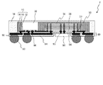
図1は、本発明による電子装置の第1実施形態を示す断面図である。電子装置1は、配線層10(第1の配線層)、および配線層20(第2の配線層)を備えている。 FIG. 1 is a cross-sectional view showing a first embodiment of an electronic device according to the present invention. The electronic device 1 includes a wiring layer 10 (first wiring layer) and a wiring layer 20 (second wiring layer).
配線層10は、ビアプラグ12(第1の導電プラグ)、絶縁樹脂14および導体配線16を有している。ビアプラグ12は、絶縁樹脂14中に形成されている。図からわかるように、ビアプラグ12は、配線層20に近づくにつれて径が小さくなるテーパ状をしている。したがって、ビアプラグ12の配線層20側の端面の面積は、その反対側の端面すなわち後述するICチップ32,36側の端面の面積よりも小さい。
The
ビアプラグ12の導体は、例えば、Cu、Ni、AuまたはAgである。絶縁樹脂14は、例えば、ポリイミド樹脂、PBO(ポリベンゾオキサゾール)樹脂、BCB(ベンゾシクロブテン)樹脂、カルド樹脂(カルド型ポリマー)またはエポキシ樹脂である。ポリイミド樹脂は、感光性ポリイミド樹脂であってもよいし、非感光性ポリイミド樹脂であってもよい。絶縁樹脂14上には、ビアプラグ12に接続された導体配線16が形成されている。
The conductor of the
配線層10の上面(第1面)上には、ICチップ32,36(電子部品)が載置されている。これらのICチップ32,36は、それぞれバンプ33,37を介して導体配線16にフリップチップ接続されている。ICチップ32と配線層10との間の間隙には、アンダーフィル樹脂34が充填されている。同様に、ICチップ36と配線層10との間の間隙には、アンダーフィル樹脂38が充填されている。ICチップ36は複数設けられており、それらは互いに積層されている。ICチップ32およびICチップ36は、例えば、それぞれCPUおよび積層メモリである。積層メモリとは、ICチップ(メモリ)を三次元的に積層し、チップ(メモリ)間を電気的に接続したものである。
また、ICチップ32,36は、配線層10上に形成された封止樹脂52によって覆われている。より詳細には、ICチップ32の側面、ならびにICチップ36の側面および上面が封止樹脂52によって覆われている。
The
配線層10の下面(第2面)上には、配線層20が形成されている。配線層20は、平面視での面積が配線層10よりも大きく、配線層10より外側まで延在している。すなわち、配線層20は、配線層10からはみ出している。
A
配線層20は、ビアプラグ22(第2の導電プラグ)および絶縁樹脂24を有している。ビアプラグ22は、絶縁樹脂24中に形成されている。このビアプラグ22は、上述のビアプラグ12と接続されている。図からわかるように、ビアプラグ22は、配線層10に近づくにつれて径が小さくなるテーパ状をしている。したがって、ビアプラグ22の配線層10側の端面の面積は、その反対側の端面すなわち後述する半田ボール60側の端面の面積よりも小さい。ビアプラグ22の導体は、ビアプラグ12と同様、例えばCu、Ni、AuまたはAgである。また、絶縁樹脂24は、例えば、エポキシ樹脂等である。上述の配線層10および配線層20からなる配線体は、電子装置1においてインターポーザとして機能する。
The
配線層10を構成する絶縁樹脂14の熱分解温度は、配線層20を構成する絶縁樹脂24の熱分解温度よりも高い。絶縁樹脂14としてPBOを用いた場合、その熱分解温度は例えば540℃である。また、絶縁樹脂24としてエポキシ樹脂を用いた場合、その熱分解温度は例えば310℃である。ここで、熱分解温度とは、10℃/分の昇温速度で熱天秤を用いて測定したときに、樹脂の重量が5重量%減となるときの温度である。なお、絶縁樹脂14,24として同種類の樹脂(例えばエポキシ樹脂)を用いる場合も、前者の方が後者よりも熱分解温度が高くなるようにする。
The thermal decomposition temperature of the insulating
配線層20のうち配線層10よりも外側の部分上には、第2の電子部品として、ICチップ42および受動部品44が載置されている。受動部品44は、例えば、デカップリングキャパシタ等のキャパシタである。ICチップ42は、封止樹脂54によって覆われている。受動部品44は、配線層20の上記外側の部分上に設けられた樹脂56によって覆われている。樹脂56は、封止樹脂54と同じ樹脂であってもよいし、異なる樹脂であってもよい。
An
また、配線層20は、多層配線構造をしており、複数の層に設けられた導体配線26と、相異なる層の導体配線26どうしを接続するビアプラグ28とを有している。最下層の導体配線26には、半田ボール60が接続されている。半田ボール60は、一部がソルダーレジスト62中に埋没している。この半田ボール60は、電子装置1の外部接続端子として機能する。
The
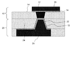
図2を参照しつつ、配線層10と配線層20との界面付近の構造の一例を説明する。本例においては、ビアプラグ22を覆うように密着金属膜72が形成されている。密着金属膜72は、ビアプラグ22上でビアプラグ12に接している。さらに、導体配線16のビアプラグ12に接する面上にも、密着金属膜74が形成されている。
An example of the structure near the interface between the
密着金属膜72,74は、Tiを含む膜(例えば、Ti、TiNまたはTiW等)、またはCr膜であることが好ましい。
The
図3〜図7を参照しつつ、本発明による電子装置の製造方法の第1実施形態として、電子装置1の製造方法を説明する。詳細な説明に先立って、図3(a)〜図3(e)を用いて、本製造方法の概要を説明する。まず、図3(a)に示すように、支持基板90上に配線層10を形成する(第1配線層形成工程)。支持基板90としては、シリコン基板、セラミック基板、ガラス基板または金属基板等を用いることができる。
The manufacturing method of the electronic device 1 will be described as a first embodiment of the manufacturing method of the electronic device according to the present invention with reference to FIGS. Prior to detailed description, an outline of the present manufacturing method will be described with reference to FIGS. 3 (a) to 3 (e). First, as shown in FIG. 3A, the
次に、図3(b)に示すように、配線層10上にICチップ32,36を載置する(電子部品載置工程)。さらに、図3(c)に示すように、ICチップ32,36を覆うように、配線層10上に封止樹脂52を形成する(封止樹脂形成工程)。続いて、図3(d)に示すように、支持基板90を除去する(支持基板除去工程)。その後、図3(e)に示すように、配線層10の下面上に、配線層20を形成する(第2配線層形成工程)。最後に、図示を省略するが、半田ボール60を形成することにより、図1に示す電子装置1を得る。
Next, as shown in FIG. 3B, IC chips 32 and 36 are placed on the wiring layer 10 (electronic component placing step). Further, as shown in FIG. 3C, a sealing
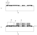
続いて、図4〜図7を用いて、本製造方法を詳細に説明する。まず、支持基板90上に絶縁樹脂14を形成し、その中にビアプラグ12を形成する。その後、絶縁樹脂14上に導体配線16を形成する(図4(a))。次に、導体配線16上にICチップ32,36をフリップチップ実装する(図4(b))。続いて、ICチップ32,36を覆うように、配線層10上に封止樹脂52を形成する。封止樹脂52の形成は、例えば、モールド成型、印刷法またはポッティング法により行うことができる(図5(a))。その後、支持基板90を除去することにより、配線層10の下面を露出させる(図5(b))。
Then, this manufacturing method is demonstrated in detail using FIGS. First, the insulating
次に、配線層10の下面上に、当該配線層10より外側まで延在するように絶縁樹脂24を形成する。このとき、絶縁樹脂24として、例えば絶縁フィルムを用いることができる。続いて、絶縁樹脂24の配線層10よりも外側の部分上に、ICチップ42および受動部品44を実装する。その後、ICチップ42を覆うように封止樹脂54を形成する(図6(a))。次に、絶縁樹脂24の上記外側の部分上の隙間を埋めるように、樹脂56を形成する。これにより、受動部品44が樹脂56で覆われる(図6(b))。
Next, an insulating
次に、ビアプラグ12に接続されるように、絶縁樹脂24中にビアプラグ22を形成する。その後、絶縁樹脂24上に、ビルドアップ配線層を形成する。例えば、エポキシ樹脂等の絶縁樹脂層中に、セミアディティブ法による導体配線26、およびレーザ加工によるビアプラグ28を交互に形成すればよい。これにより、配線層20が形成される(図7)。その後、ソルダーレジスト62および半田ボール60を形成することにより、図1の電子装置1が得られる。なお、配線層20の形成は、予め形成した多層配線層を配線層20として配線層10の下面に接着することにより行ってもよい。
Next, the via
以上の説明から明らかなように、配線層10,20のビルドアップ方向は、それぞれ各図中の上向きおよび下向きである。これに伴い、上述したとおり、ビアプラグ12のICチップ32,36側の端面は配線層20側の端面よりも面積が大きく、ビアプラグ22の半田ボール60側の端面は配線層10側の端面よりも面積が大きくなっている。
As is clear from the above description, the build-up directions of the wiring layers 10 and 20 are upward and downward in the drawings, respectively. Accordingly, as described above, the end surface of the via plug 12 on the
本実施形態の効果を説明する。上記製造方法においては、ICチップ32,36が載置される配線層10を支持基板90上に形成する一方で、配線層20を支持基板90の除去後に形成している。これにより、絶縁樹脂24として、絶縁樹脂14よりも熱分解温度が低い樹脂を用いることができないという制約から免れることができる。したがって、絶縁樹脂14としては微細加工に適した樹脂を用い、一方で絶縁樹脂24としては比較的安価な樹脂を用いることが可能となる。これにより、低コストながらも、配線層10とICチップ32,36との微細な接続を得られる電子装置1の製造方法が実現されている。
The effect of this embodiment will be described. In the above manufacturing method, the
さらに、配線層20が配線層10より外側まで延在している。これにより、配線層10の面積を小さく抑えつつ、半田ボール60が設けられる面(すなわち配線層20の下面)の面積を充分に大きくできる。このため、コストの増大を招くことなく、電子装置1を他の電子装置やマザーボード等に容易に実装することができる。これに対して、配線層10および配線層20の面積が互いに等しい場合に、実装容易性を高めるべく配線層20の面積を大きくしようとすれば、それに伴って配線層10の面積も大きくせざるを得ない。すると、配線層10には微細加工に適した比較的高価な樹脂が用いられるため、電子装置1の製造コストが増大してしまう。一方、低コスト化を図るべく配線層10の面積を小さくすれば、配線層20の面積も小さくなり、実装容易性が損なわれてしまう。本実施形態によれば、かかるディレンマを解消し、低コストおよび実装容易性を両立させることができる。
Further, the
剛性の高い支持基板90上にて導体配線16の配線パターンを形成しているので、微細な導体配線16を得ることができる。また、支持基板90上で配線層10とICチップ32,36とを接合しているので、配線層10とICチップ32,36とを微細ピッチでバンプ接続することができる。このことは、配線層数の減少、およびICチップ32,36のサイズの縮小につながる。
Since the wiring pattern of the
さらに、支持基板90を除去した後に配線層20を形成しているので、配線層20を構成する絶縁樹脂24を絶縁樹脂14に比べて厚く形成することができる。これにより、絶縁樹脂24の応力緩和機能が高まり、電子装置1の信頼性向上につながる。
Furthermore, since the
第2配線層形成工程においては、第1配線層形成工程において形成される配線層10を構成する絶縁樹脂14よりも熱分解温度が低い樹脂が、配線層20を構成する絶縁樹脂24として用いられている。これにより、配線層20を配線層10上に好適に形成することができる。
In the second wiring layer forming step, a resin having a lower thermal decomposition temperature than the insulating
電子装置1においては、配線層20を構成する絶縁樹脂24として、配線層10を構成する絶縁樹脂14よりも熱分解温度が低い樹脂を用いることができる。したがって、絶縁樹脂14としては微細加工に適した樹脂を用い、一方で絶縁樹脂24としては比較的安価な樹脂を用いることが可能となる。これにより、低コストながらも、配線層10とICチップ32,36との微細な接続を得られる電子装置1が実現されている。
In the electronic device 1, a resin having a lower thermal decomposition temperature than the insulating
さらに、電子装置1においては、配線層10と配線層20とが直接に接しており、これらの層の間にコア層が設けられていない。コア層に形成されるビアプラグは、一般に、通常の配線層に形成されるビアプラグに比べると微細化するのが困難であるため、電子装置全体の微細化を妨げてしまうという問題がある。この点、電子装置1においては、コア層が設けられていないため、かかる問題は生じない。
Further, in the electronic device 1, the
ICチップ32,36を覆うように封止樹脂52が設けられている。これにより、支持基板90が除去された後も配線体の形状を保持することができる。このため、半田ボール60について高いコプラナリティが得られる。特に本実施形態においては、配線層20の配線層10よりも外側の部分上にも、樹脂56が形成されている。これにより、かかる効果が一層高められている。
A sealing
支持基板90としてシリコン基板を用いた場合、絶縁基板を用いる場合に比して、熱膨張の影響を小さく抑えることができる。これにより、配線層10とICチップ32,36との接続を一層微細化することができる。
When a silicon substrate is used as the
絶縁樹脂14としてポリイミド樹脂、PBO樹脂、BCB樹脂またはカルド樹脂を用いた場合、微細加工に適した絶縁樹脂14が実現される。また、絶縁樹脂24としてエポキシ樹脂を用いた場合、低コストで絶縁樹脂24を得ることができる。
When polyimide resin, PBO resin, BCB resin, or cardo resin is used as the insulating
ビアプラグ22を覆うように密着金属膜72が設けられている(図2参照)。これにより、ビアプラグ22と絶縁樹脂24との間で強固な結合が得られる。また、導体配線16のビアプラグ12に接する面上に密着金属膜74が設けられている(図2参照)。これにより、導体配線16と絶縁樹脂14との間で強固な結合が得られる。これらは、電子装置1の信頼性の向上に寄与する。密着金属膜72,74がTiを含んでいるか、Crからなる場合、樹脂に対する特に高い密着性を得ることができる。
An
配線層20のうち配線層10よりも外側の部分上に、ICチップ42および受動部品44が載置されている。これにより、電子装置1の一層の高機能化・高性能化を図ることができる。
(第2実施形態)
An
(Second Embodiment)
図8は、本発明による電子装置の第2実施形態を示す断面図である。電子装置2は、配線層10(第1の配線層)、および配線層80(第2の配線層)を備えている。配線層10の構成は、図1で説明したものと同様である。
FIG. 8 is a sectional view showing a second embodiment of the electronic device according to the present invention. The
配線層80は、配線層10の下面上に形成され、配線層10より外側まで延在している。この配線層80は、ソルダーレジスト84と、その中に形成された導体配線86とを有している。ソルダーレジスト84としては、絶縁樹脂14よりも熱分解温度が低い樹脂が用いられる。この配線層80中には、ビアプラグ82(第2の導電プラグ)が形成されている。このビアプラグ82は、半田ボール60の一部分、具体的には半田ボール60のうちソルダーレジスト84中に埋没している部分に相当する。図からわかるように、ビアプラグ82は、配線層10に近づくにつれて径が小さくなるテーパ状をしている。したがって、ビアプラグ82の配線層10側の端面の面積は、その反対側の端面の面積よりも小さい。
The
さらに、配線層10の下面にICチップ92がフリップチップ実装されている。つまり、当該下面にバンプ93を介してICチップ92が接続され、配線層10とICチップ92との間の間隙にアンダーフィル樹脂94が充填されている。
Further, an
配線層80のうち配線層10よりも外側の部分上には、樹脂56が形成されている。本実施形態において樹脂56は、封止樹脂52の側面および上面の双方を覆っている。
A
図9〜図12を参照しつつ、本発明による電子装置の製造方法の第2実施形態として、電子装置2の製造方法を説明する。まず、支持基板90上に絶縁樹脂14、ビアプラグ12および導体配線16を形成する(図9(a))。続いて、導体配線16上にICチップ32,36をフリップチップ実装する(図9(b))。
A method for manufacturing the
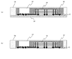
次に、ICチップ32,36を覆うように、配線層10上に封止樹脂52を形成する(図10(a))。その後、支持基板90を除去することにより、配線層10の下面を露出させる(図10(b))。続いて、配線層10の下面上に、当該配線層10より外側まで延在するように支持シート91を形成する(図10(c))。
Next, a sealing
次に、封止樹脂52を覆うようにして、支持シート91の配線層10よりも外側の部分上に樹脂56を形成する(図11(a))。その後、支持シート91を剥離する(図11(b))。次に、配線層10の下面上に導体配線86を形成した後、それを覆うようにソルダーレジスト84を形成する。さらに、ソルダーレジスト84をパターニングし、半田ボール60が形成される部分およびICチップ92が実装される部分を開口する(図12(a))。これにより、配線層80が形成される。続いて、配線層10の下面にICチップ92をフリップチップ実装する(図12(b))。その後、半田ボール60を形成することにより、図8の電子装置2が得られる。
Next, a
本実施形態は、上述した第1実施形態が奏する効果に加えて、以下の効果を奏することができる。配線層80を構成する樹脂としてソルダーレジスト84が用いられているため、電子装置2の一層の低コスト化を図ることができる。さらに、配線層10の上面だけでなく下面にも電子部品(ICチップ92)が実装されている。これにより、電子装置2の一層の高機能化・高性能化を図ることができる。
(第3実施形態)
In addition to the effect which 1st Embodiment mentioned above has, this embodiment can have the following effects. Since the solder resist 84 is used as the resin constituting the
(Third embodiment)
図13は、本発明による電子装置の第3実施形態を示す断面図である。電子装置3は、配線層10、および配線層80を備えている。電子装置3は、配線層80が多層配線構造を有している点で、図8の電子装置2と相違する。本実施形態において配線層80は、配線層10の下面上に設けられた絶縁樹脂84aと、その上に設けられたソルダーレジスト84bとを含んでいる。
FIG. 13 is a cross-sectional view showing a third embodiment of the electronic device according to the present invention. The electronic device 3 includes a
本実施形態の配線層80中には、複数の層に設けられた導体配線86と、導体配線86に接続されたビアプラグ83(第2の導電プラグ)とが形成されている。図からわかるように、ビアプラグ83は、配線層10に近づくにつれて径が小さくなるテーパ状をしている。したがって、ビアプラグ83の配線層10側の端面の面積は、その反対側の端面の面積よりも小さい。また、電子装置2においてはバンプ93が直接にビアプラグ12に接続されていたのに対し、この電子装置3においては、バンプ93が導体配線86(およびビアプラグ83)を介してビアプラグ12に接続されている。電子装置3のその他の構成は、電子装置2と同様である。
In the
図14(a)および図14(b)を参照しつつ、本発明による電子装置の製造方法の第3実施形態として、電子装置3の製造方法を説明する。まず、図9〜図11で説明したのと同様にして、図11(b)に示す構造体を準備する。 With reference to FIGS. 14A and 14B, a method of manufacturing the electronic device 3 will be described as a third embodiment of the method of manufacturing the electronic device according to the present invention. First, the structure shown in FIG. 11B is prepared in the same manner as described with reference to FIGS.
次に、ビアプラグ12に接続されるように、配線層10の下面上に1層目の導体配線86を形成する。その後、それを覆うように絶縁樹脂84aを形成する。さらに、絶縁樹脂84a中に、導体配線86に接続されるようにビアプラグ83を形成する。続いて、ビアプラグ83に接続されるように、絶縁樹脂84a上に2層目の導体配線86を形成する。その後、それを覆うようにソルダーレジスト84bを形成する。
Next, a first-
次に、ソルダーレジスト84bをパターニングし、半田ボール60が形成される部分およびICチップ92が実装される部分を開口する(図14(a))。これにより、配線層80が形成される。続いて、絶縁樹脂84a上にICチップ92をフリップチップ実装する(図14(b))。その後、半田ボール60を形成することにより、図13の電子装置3が得られる。本実施形態においても、第2実施形態と同様の効果が奏される。
Next, the solder resist 84b is patterned to open a portion where the
本発明による電子装置およびその製造方法は、上記実施形態に限定されるものではなく、様々な変形が可能である。例えば、上記実施形態においては配線層10の上面または下面に載置される電子部品としてICチップを例示したが、当該電子部品はコンデンサ等の受動部品であってもよい。また、電子装置に電子部品を設けることは必須ではない。
The electronic device and the manufacturing method thereof according to the present invention are not limited to the above-described embodiment, and various modifications are possible. For example, in the above embodiment, the IC chip is exemplified as the electronic component placed on the upper surface or the lower surface of the
上記実施形態においては電子装置に半田ボールが設けられた例を示したが、半田ボールを設けることは必須ではない。半田ボールが設けられていない場合、導体配線のランド部分が外部電極端子に相当する。図1の電子装置1を例にとると、導体配線26のうち半田ボール60が接続されている部分がランド部分である。
In the above embodiment, an example in which a solder ball is provided in the electronic device has been described. However, it is not essential to provide a solder ball. When the solder ball is not provided, the land portion of the conductor wiring corresponds to the external electrode terminal. Taking the electronic device 1 of FIG. 1 as an example, a portion of the
また、第2の配線層は、第1の配線層の周囲の全体からはみ出していてもよいし、一部のみからはみ出していてもよい。前者の例を図15に、後者の例を図16(a)〜図16(c)に示す。これらの平面図においては、第1および第2の配線層の外周をそれぞれ線L1,L2で示し、両配線層が重なった部分に斜線を付している。図15では第1の配線層の4辺の全てから第2の配線層がはみ出している。一方、図16(a)、図16(b)および図16(c)では、それぞれ第1の配線層の3辺、2辺および1辺から第2の配線層がはみ出している。 Further, the second wiring layer may protrude from the entire periphery of the first wiring layer, or may protrude from only a part thereof. The former example is shown in FIG. 15, and the latter example is shown in FIGS. 16 (a) to 16 (c). In these plan views, the outer peripheries of the first and second wiring layers are indicated by lines L1 and L2, respectively, and the portions where both wiring layers overlap are hatched. In FIG. 15, the second wiring layer protrudes from all four sides of the first wiring layer. On the other hand, in FIG. 16A, FIG. 16B, and FIG. 16C, the second wiring layer protrudes from three sides, two sides, and one side of the first wiring layer, respectively.
1 電子装置
2 電子装置
10 配線層
12 ビアプラグ
14 絶縁樹脂
16 導体配線
20 配線層
22 ビアプラグ
24 絶縁樹脂
26 導体配線
28 ビアプラグ
32 ICチップ
33 バンプ
34 アンダーフィル樹脂
36 ICチップ
37 バンプ
38 アンダーフィル樹脂
42 ICチップ
44 受動部品
52 封止樹脂
54 封止樹脂
56 樹脂
60 半田ボール
62 ソルダーレジスト
72 密着金属膜
80 配線層
82 ビアプラグ
84 ソルダーレジスト
84a 絶縁樹脂
84b ソルダーレジスト
86 導体配線
90 支持基板
91 支持シート
92 ICチップ
93 バンプ
94 アンダーフィル樹脂
DESCRIPTION OF SYMBOLS 1
Claims (10)
前記複数の導体配線と前記第1絶縁層の前記第1裏面の一部を覆い、第1辺、前記第1辺とは反対側の第2辺、前記第1絶縁層の前記第1裏面と対向する第2表面、前記第2表面とは反対側の第2裏面を含む第2絶縁層と、
前記第1絶縁層の前記第1表面から前記第1裏面を貫通し、端部が前記複数の配線群の少なくとも一つと電気的および機械的に接続され、他端部が前記複数の導体配線と電気的および機械的に接続された複数の導電プラグ群と、
前記第1表面上に設置され、第1主面上にCPU回路および複数の第1電極を有する第1チップと、
前記第1表面上に設置され、第2主面上に、第1辺、その反対側の第2辺およびメモリ回路を有し、積層され、複数の貫通する電極を介して接続された複数の第2チップと、
前記第2絶縁層の前記第2裏面上に設置された複数の外部端子と、
前記第1チップ、前記複数の第2チップと前記第1表面を樹脂により封止した封止体と、を含み、
前記複数の貫通する電極は、前記複数の第2チップの中央部に配置された複数の第1の貫通する電極と、前記中央部より外側の前記第2チップの第1辺側に配置された複数の第2の貫通する電極と、前記中央部より外側の前記第2チップの第2辺側に配置された複数の第3の貫通する電極と、を含み、
前記複数の配線群は、第1配線群を含み、
前記第1配線群は、断面視において前記複数の第2チップの直下に配置され、前記複数の第2チップの中央から前記複数の第2チップの第1辺へ延在する第1配線と前記複数の第2チップ中央から前記複数の第2チップの第2辺へ延在する第2配線を含み、前記第1配線の端部は前記複数の第1の貫通する電極の一つと接続され、前記第2配線の端部は前記複数の第1の貫通する電極の他の一つと接続され、前記第1配線の端部と前記第2配線の端部は対向して配置され、
前記複数の導電プラグ群は、第1導電プラグ群を含み、
前記第1導電プラグ群は、断面視において前記第2チップの直下に配置され、前記複数の第2チップの中央部から前記複数の第2チップの第1辺の間に配置された第1プラグと前記複数の第2チップの中央部から前記複数の第2チップの第2辺の間に配置された第2プラグを含み、前記第1プラグの端部は前記第1配線の他端部と接続され、前記第2プラグの端部は前記第2配線の他端部と接続され、
前記第1プラグの他端部は前記複数の導体配線の一つと接続され、
前記第2プラグの他端部は前記複数の導体配線の他の一つと接続され、
前記複数の配線群は、前記第1絶縁層の外周辺の内部に形成されており、
前記複数の導体配線は前記第1絶縁層の内部から前記第1絶縁層の外周辺の外部へ延在して形成されていることを特徴とする電子装置。 A first surface on which a plurality of wiring groups are installed, the first surface is on the opposite side, and a first back surface on which a plurality of conductor wirings are installed, a first side, and a first side opposite to the first side A first insulating layer including two sides;
Covering the plurality of conductor wirings and a part of the first back surface of the first insulating layer; a first side; a second side opposite to the first side; the first back surface of the first insulating layer; A second insulating layer including an opposing second surface, a second back surface opposite to the second surface;
The first insulating layer penetrates the first back surface from the first surface, an end is electrically and mechanically connected to at least one of the plurality of wiring groups, and the other end is connected to the plurality of conductor wirings. A plurality of conductive plug groups electrically and mechanically connected;
A first chip installed on the first surface and having a CPU circuit and a plurality of first electrodes on the first main surface;
A plurality of first electrodes arranged on the first surface, having a first side, a second side opposite to the first side, and a memory circuit on the second main surface, and being connected via a plurality of penetrating electrodes; A second chip;
A plurality of external terminals installed on the second back surface of the second insulating layer;
Including the first chip, the plurality of second chips, and a sealing body in which the first surface is sealed with a resin;
The plurality of penetrating electrodes are disposed on the first side of the second chip outside the central portion and the plurality of first penetrating electrodes disposed on the central portion of the plurality of second chips. A plurality of second penetrating electrodes, and a plurality of third penetrating electrodes disposed on the second side of the second chip outside the central portion,
The plurality of wiring groups include a first wiring group,
The first wiring group is disposed immediately below the plurality of second chips in a cross-sectional view, and extends from the center of the plurality of second chips to the first side of the plurality of second chips; Including a second wiring extending from the center of the plurality of second chips to the second side of the plurality of second chips, and an end of the first wiring is connected to one of the plurality of first penetrating electrodes, An end of the second wiring is connected to another one of the plurality of first penetrating electrodes, and an end of the first wiring and an end of the second wiring are arranged to face each other,
The plurality of conductive plug groups includes a first conductive plug group,
The first conductive plug group is disposed immediately below the second chip in a cross-sectional view, and is disposed between a central portion of the plurality of second chips and a first side of the plurality of second chips. And a second plug disposed between a center portion of the plurality of second chips and a second side of the plurality of second chips, and an end portion of the first plug is connected to the other end portion of the first wiring. Connected, the end of the second plug is connected to the other end of the second wiring,
The other end of the first plug is connected to one of the plurality of conductor wires;
The other end of the second plug is connected to another one of the plurality of conductor wirings,
The plurality of wiring groups are formed inside an outer periphery of the first insulating layer,
The electronic device, wherein the plurality of conductor wirings are formed to extend from the inside of the first insulating layer to the outside of the outer periphery of the first insulating layer.
前記第2配線群は、断面視において前記複数の第2チップの直下に配置され、前記複数の第2チップの第1辺側の周辺部から前記複数の第2チップの中央部へ延在する第3配線と前記複数の第2チップの第1辺側の周辺部から前記複数の第2チップの第1辺の外部へ延在する第4配線を含み、前記第3配線の端部は前記複数の第2の貫通する電極の一つと接続され、前記第4配線の端部は前記複数の第2の貫通する電極の他の一つと接続され、前記第3配線の端部と前記第4配線の端部は対向して配置されていることを特徴とする請求項1記載の電子装置。 The plurality of wiring groups further include a second wiring group,
The second wiring group is disposed immediately below the plurality of second chips in a cross-sectional view, and extends from a peripheral portion on the first side of the plurality of second chips to a central portion of the plurality of second chips. Including a third wiring and a fourth wiring extending from the first side of the plurality of second chips to the outside of the first side of the plurality of second chips, the end of the third wiring being Connected to one of the plurality of second penetrating electrodes, the end of the fourth wiring connected to the other one of the plurality of second penetrating electrodes, and the end of the third wiring to the fourth The electronic device according to claim 1, wherein the ends of the wiring are arranged to face each other.
前記第2導電プラグ群は、断面視において前記第2チップの直下に配置され、前記複数の第2チップの中央部から前記複数の第2チップの第1辺の間に配置された第3プラグを含み、前記第3プラグの端部は前記第3配線の他端部と接続され、前記第4配線の他端部は前記第1チップの前記複数の第1電極の一つと接続されていることを特徴とする請求項2記載の電子装置。 The plurality of conductive plug groups includes a second conductive plug group,
The second conductive plug group is disposed immediately below the second chip in a cross-sectional view, and a third plug disposed between a central portion of the plurality of second chips and a first side of the plurality of second chips. And an end of the third plug is connected to the other end of the third wiring, and the other end of the fourth wiring is connected to one of the plurality of first electrodes of the first chip. The electronic device according to claim 2.
前記第3配線群は、断面視において前記複数の第2チップの直下に配置され、前記複数の第2チップの第2辺側の周辺部から前記複数の第2チップの中央部へ延在する第5配線と、断面視において前記複数の第2チップの直下から前記複数の第2チップの外部に渡って配置され、前記複数の第2チップの第2辺側の周辺部から前記複数の第2チップの第2辺の外部へ延在する第6配線を含み、前記第5配線の端部は前記複数の第3の貫通する電極の一つと接続され、前記第6配線の端部は前記複数の第3の貫通する電極の他の一つと接続され、前記第5配線の端部と前記第6配線の端部は対向して配置されていることを特徴とする請求項1乃至請求項3の何れかに記載の電子装置。 The plurality of wiring groups further includes a third wiring group,
The third wiring group is arranged immediately below the plurality of second chips in a cross-sectional view, and extends from the peripheral portion on the second side of the plurality of second chips to the central portion of the plurality of second chips. The fifth wiring and the plurality of second chips are arranged from directly under the plurality of second chips to the outside of the plurality of second chips in a cross-sectional view, and from the peripheral portion on the second side of the plurality of second chips. Including a sixth wiring extending to the outside of the second side of the two chips, an end of the fifth wiring connected to one of the plurality of third penetrating electrodes, and an end of the sixth wiring 2. The device according to claim 1, wherein the second wiring is connected to another one of the plurality of third penetrating electrodes, and an end of the fifth wiring and an end of the sixth wiring are arranged to face each other. 4. The electronic device according to any one of 3.
前記第3導電プラグ群は、断面視において前記第2チップの直下に配置され、前記複数の第2チップの中央部から前記複数の第2チップの第2辺の間に配置された第4プラグと、前記複数の第2チップの第2辺の外部に設置された第5プラグと、を含み、
前記第4プラグの端部は前記第5配線の他端部と接続され、前記第5プラグの端部は前記第6配線の他端部と接続されていることを特徴とする請求項4記載の電子装置。 The plurality of conductive plug groups further includes a third conductive plug group,
The third conductive plug group is disposed immediately below the second chip in a cross-sectional view, and is a fourth plug disposed between a central portion of the plurality of second chips and a second side of the plurality of second chips. And a fifth plug installed outside the second side of the plurality of second chips,
5. The end of the fourth plug is connected to the other end of the fifth wiring, and the end of the fifth plug is connected to the other end of the sixth wiring. Electronic devices.
前記第2領域上に第3チップが搭載され、
前記封止体は、更に前記第3チップと前記第2領域の一部を前記樹脂により封止することを特徴とする請求項1乃至請求項5の何れかに記載の電子装置。 The second surface of the second insulating layer has a first region overlapping the first insulating layer and a second region not overlapping the first insulating layer;
A third chip is mounted on the second region;
The electronic device according to claim 1, wherein the sealing body further seals a part of the third chip and the second region with the resin.
前記第2領域上に受動部品が搭載され、
前記封止体は、更に前記受動部品と前記第2領域の一部を前記樹脂により封止することを特徴とする請求項1乃至請求項5の何れかに記載の電子装置。 The second surface of the second insulating layer has a first region overlapping the first insulating layer and a second region not overlapping the first insulating layer;
Passive components are mounted on the second region,
The electronic device according to claim 1, wherein the sealing body further seals the passive component and a part of the second region with the resin.
Priority Applications (1)
| Application Number | Priority Date | Filing Date | Title |
|---|---|---|---|
| JP2014026162A JP2014096609A (en) | 2014-02-14 | 2014-02-14 | Electronic apparatus |
Applications Claiming Priority (1)
| Application Number | Priority Date | Filing Date | Title |
|---|---|---|---|
| JP2014026162A JP2014096609A (en) | 2014-02-14 | 2014-02-14 | Electronic apparatus |
Related Parent Applications (1)
| Application Number | Title | Priority Date | Filing Date |
|---|---|---|---|
| JP2012182958A Division JP5607692B2 (en) | 2012-08-22 | 2012-08-22 | Electronic equipment |
Related Child Applications (1)
| Application Number | Title | Priority Date | Filing Date |
|---|---|---|---|
| JP2015095858A Division JP2015146467A (en) | 2015-05-08 | 2015-05-08 | Electronic apparatus |
Publications (1)
| Publication Number | Publication Date |
|---|---|
| JP2014096609A true JP2014096609A (en) | 2014-05-22 |
Family
ID=50939399
Family Applications (1)
| Application Number | Title | Priority Date | Filing Date |
|---|---|---|---|
| JP2014026162A Pending JP2014096609A (en) | 2014-02-14 | 2014-02-14 | Electronic apparatus |
Country Status (1)
| Country | Link |
|---|---|
| JP (1) | JP2014096609A (en) |
Cited By (1)
| Publication number | Priority date | Publication date | Assignee | Title |
|---|---|---|---|---|
| JP2016046519A (en) * | 2014-08-19 | 2016-04-04 | インテル コーポレイション | Both sides solder resist layer of coreless package, package having embedded interconnect bridge, and manufacturing method therefor |
Citations (5)
| Publication number | Priority date | Publication date | Assignee | Title |
|---|---|---|---|---|
| WO2000021135A1 (en) * | 1998-10-02 | 2000-04-13 | Hitachi, Ltd. | Semiconductor device and method for manufacturing the same |
| JP2001291819A (en) * | 2000-03-07 | 2001-10-19 | Fujitsu Ltd | Multilayer interconnected module with discrete capacitor and component buried therein and its manufacturing method |
| JP2003158239A (en) * | 2001-11-22 | 2003-05-30 | Sony Corp | Multichip circuit module and its manufacturing method |
| JP2003309215A (en) * | 2002-02-15 | 2003-10-31 | Nec Electronics Corp | Semiconductor device and method of manufacturing the same |
| JP2005191172A (en) * | 2003-12-25 | 2005-07-14 | Elpida Memory Inc | Semiconductor integrated circuit |
-
2014
- 2014-02-14 JP JP2014026162A patent/JP2014096609A/en active Pending
Patent Citations (5)
| Publication number | Priority date | Publication date | Assignee | Title |
|---|---|---|---|---|
| WO2000021135A1 (en) * | 1998-10-02 | 2000-04-13 | Hitachi, Ltd. | Semiconductor device and method for manufacturing the same |
| JP2001291819A (en) * | 2000-03-07 | 2001-10-19 | Fujitsu Ltd | Multilayer interconnected module with discrete capacitor and component buried therein and its manufacturing method |
| JP2003158239A (en) * | 2001-11-22 | 2003-05-30 | Sony Corp | Multichip circuit module and its manufacturing method |
| JP2003309215A (en) * | 2002-02-15 | 2003-10-31 | Nec Electronics Corp | Semiconductor device and method of manufacturing the same |
| JP2005191172A (en) * | 2003-12-25 | 2005-07-14 | Elpida Memory Inc | Semiconductor integrated circuit |
Cited By (4)
| Publication number | Priority date | Publication date | Assignee | Title |
|---|---|---|---|---|
| JP2016046519A (en) * | 2014-08-19 | 2016-04-04 | インテル コーポレイション | Both sides solder resist layer of coreless package, package having embedded interconnect bridge, and manufacturing method therefor |
| US9704735B2 (en) | 2014-08-19 | 2017-07-11 | Intel Corporation | Dual side solder resist layers for coreless packages and packages with an embedded interconnect bridge and their methods of fabrication |
| US10629469B2 (en) | 2014-08-19 | 2020-04-21 | Intel Corporation | Solder resist layers for coreless packages and methods of fabrication |
| US11443970B2 (en) | 2014-08-19 | 2022-09-13 | Intel Corporation | Methods of forming a package substrate |
Similar Documents
| Publication | Publication Date | Title |
|---|---|---|
| US10879227B2 (en) | Electronic device | |
| JP4956128B2 (en) | Manufacturing method of electronic device | |
| JP4790297B2 (en) | Semiconductor device and manufacturing method thereof | |
| JP2008091639A (en) | Electronic equipment, and manufacturing method thereof | |
| JP6314070B2 (en) | Fingerprint recognition semiconductor device, method for manufacturing fingerprint recognition semiconductor device, and semiconductor device | |
| US8168475B2 (en) | Semiconductor package formed within an encapsulation | |
| CN105990270B (en) | Electronic package and manufacturing method thereof | |
| US20100230823A1 (en) | Semiconductor device, electronic device and method of manufacturing semiconductor device | |
| JP2009141169A (en) | Semiconductor device | |
| JP2018137474A (en) | Electronic apparatus | |
| JP5607692B2 (en) | Electronic equipment | |
| JP6335265B2 (en) | Electronic equipment | |
| JP2014096609A (en) | Electronic apparatus | |
| JP7197448B2 (en) | electronic device | |
| JP2018050077A (en) | Electronic apparatus | |
| JP2019036742A (en) | Electronic apparatus | |
| JP2015146467A (en) | Electronic apparatus | |
| JP2018137341A (en) | Electronic device and manufacturing method thereof |
Legal Events
| Date | Code | Title | Description |
|---|---|---|---|
| A621 | Written request for application examination |
Free format text: JAPANESE INTERMEDIATE CODE: A621 Effective date: 20140214 |
|
| A977 | Report on retrieval |
Free format text: JAPANESE INTERMEDIATE CODE: A971007 Effective date: 20140827 |
|
| A131 | Notification of reasons for refusal |
Free format text: JAPANESE INTERMEDIATE CODE: A131 Effective date: 20150310 |
|
| A02 | Decision of refusal |
Free format text: JAPANESE INTERMEDIATE CODE: A02 Effective date: 20151006 |