JP2014070363A - Baseboard package and construction method for baseboard using the same - Google Patents

Baseboard package and construction method for baseboard using the same Download PDF

Info

Publication number
JP2014070363A
JP2014070363A JP2012215631A JP2012215631A JP2014070363A JP 2014070363 A JP2014070363 A JP 2014070363A JP 2012215631 A JP2012215631 A JP 2012215631A JP 2012215631 A JP2012215631 A JP 2012215631A JP 2014070363 A JP2014070363 A JP 2014070363A
Authority
JP
Japan
Prior art keywords
baseboard
skirting board
wall
wound
packing box
Prior art date
Legal status (The legal status is an assumption and is not a legal conclusion. Google has not performed a legal analysis and makes no representation as to the accuracy of the status listed.)
Pending
Application number
JP2012215631A
Other languages
Japanese (ja)
Inventor
Shinichiro Shinoda
真一郎 信田
Current Assignee (The listed assignees may be inaccurate. Google has not performed a legal analysis and makes no representation or warranty as to the accuracy of the list.)
Panasonic Corp
Original Assignee
Panasonic Corp
Priority date (The priority date is an assumption and is not a legal conclusion. Google has not performed a legal analysis and makes no representation as to the accuracy of the date listed.)
Filing date
Publication date
Application filed by Panasonic Corp filed Critical Panasonic Corp
Priority to JP2012215631A priority Critical patent/JP2014070363A/en
Publication of JP2014070363A publication Critical patent/JP2014070363A/en
Pending legal-status Critical Current

Links

Images

Landscapes

  • Packaging Of Machine Parts And Wound Products (AREA)

Abstract

【課題】幅木を小さくロール状に巻いた状態で保管することができ、幅木の施工や持ち運びが容易で且つ幅木が汚れ難い幅木梱包品及びこれを用いた幅木の施工方法を提供する。
【解決手段】湾曲変形可能で且つ切断可能な帯状の幅木2を備える。ロール状に巻いた幅木2を回動可能に収納する梱包箱4を備える。梱包箱4が、巻かれた状態で前記梱包箱4に収納された幅木2を引き出すための引出口46を有する。
【選択図】図1
[PROBLEMS] To provide a skirting board package that can be stored in a state where a skirting board is wound in a small roll, is easy to carry and carry around, and is difficult to get dirty, and a skirting board construction method using the skirting board. provide.
A strip-shaped baseboard 2 that can be deformed and cut is provided. A packing box 4 is provided for rotatably storing a baseboard 2 wound in a roll shape. The packaging box 4 has an outlet 46 for pulling out the skirting board 2 stored in the packaging box 4 in a wound state.
[Selection] Figure 1

Description

本発明は梱包箱に幅木を梱包した幅木梱包品、及びこれを用いた幅木の施工方法に関する。   The present invention relates to a baseboard packaged product in which a baseboard is packed in a packing box, and a baseboard construction method using the baseboard package.

特許文献1には柔軟弾性を有する幅木が開示されている。   Patent Document 1 discloses a baseboard having flexible elasticity.

特開2003−184295号公報JP 2003-184295 A

ところで、湾曲変形可能な幅木はロール状に巻くことが可能である。しかし、このようにロール状に巻いた幅木はその弾性力によって外側に広がりやすく、小さなロール状にした状態で維持することが難しい。このため、幅木の施工がし難く、また、持ち運びもし難い。また、長尺な幅木が広がった状態で作業スペースに置かれると、作業スペースを狭めてしまい、この点でも施工性が良くない。また、ごみや埃等によって幅木が汚れる可能性もある。   By the way, a base plate that can be bent and deformed can be wound into a roll. However, the baseboard wound in a roll shape in this way tends to spread outward due to its elastic force and is difficult to maintain in a small roll shape. For this reason, it is difficult to construct skirting boards and to carry them. Moreover, if it is placed in a work space with a long baseboard spread, the work space is narrowed, and the workability is not good in this respect. In addition, there is a possibility that the skirting board is soiled by dust or dust.

本発明は前記事情に鑑みてなされたものであって、幅木を小さくロール状に巻いた状態で且つ幅木が汚れ難い状態で保管することができ、幅木の施工や持ち運びが容易な幅木梱包品及びこれを用いた幅木の施工方法を提供することを課題とする。   The present invention has been made in view of the above circumstances, and can be stored in a state in which the skirting board is wound in a small roll shape and the skirting board is difficult to get dirty, and the skirting board is easy to construct and carry. It is an object of the present invention to provide a wooden packing product and a construction method of a baseboard using the same.

前記課題を解決するために本発明の幅木梱包品は、湾曲変形可能で且つ切断可能な帯状の幅木と、ロール状に巻いた前記幅木を回動可能に収納する梱包箱を備え、前記梱包箱が、前記巻かれた状態で前記梱包箱に収納された前記幅木を引き出すための引出口を有することを特徴とする幅木梱包品。   In order to solve the above-mentioned problems, the baseboard package of the present invention comprises a belt-like baseboard that can be bent and cut, and a packaging box that rotatably stores the baseboard wound in a roll shape, A baseboard packaged article, wherein the packing box has an outlet for pulling out the baseboard stored in the packing box in the rolled state.

また、前記幅木の曲げ弾性率が1400MPa以上1600MPa以下であることが好ましい。   Moreover, it is preferable that the bending elastic modulus of the baseboard is 1400 MPa or more and 1600 MPa or less.

また、前記幅木が前記梱包箱に内径寸法を800mm以上1000mm以下として巻かれた状態で収納されることが好ましい。   Moreover, it is preferable that the said skirting board is accommodated in the state wound by making the internal diameter dimension into 800 mm or more and 1000 mm or less by the said packaging box.

また、前記幅木が巻き取られるパッドを備え、前記幅木が前記パッドに巻き取られた状態で前記梱包箱に収納されることが好ましい。   Moreover, it is preferable to provide the pad by which the said base board is wound up, and to accommodate the said base board in the state wound up by the said pad.

また、前記幅木がその表面を外側に向けて巻かれた状態で前記梱包箱に収納されることが好ましい。   Moreover, it is preferable that the said skirting board is accommodated in the said packaging box in the state wound toward the outer side.

また、本発明の幅木の施工方法は、前記幅木梱包品を用いた幅木の施工方法であって、前記幅木を前記梱包箱の前記引出口から引き出しながら壁に接着することを特徴とする。   The baseboard construction method of the present invention is a baseboard construction method using the baseboard packaged product, wherein the baseboard is adhered to a wall while being pulled out from the outlet of the packing box. And

また、前記壁に接着された幅木にピンネイルを打ち込んで前記壁に固着することが好ましい。   Further, it is preferable that a pin nail is driven into a skirting board bonded to the wall to be fixed to the wall.

また、前記引出口から引き出された幅木を前記壁の隅部又は端部に対応する部分で切断することが好ましい。   Moreover, it is preferable to cut | disconnect the baseboard pulled out from the said outlet in the part corresponding to the corner part or edge part of the said wall.

本発明にあっては、ロール状に巻いた幅木をその外側を梱包箱によって支持した状態で梱包箱に収納することができ、幅木を小さくロール状にした状態で保管することができる。また、これにより幅木の施工や持ち運びが容易になる。また、幅木は梱包箱に収納して汚れ難い状態で保管することができる。また、幅木を施工する際には、梱包箱に巻かれた状態で収納された幅木を引出口から引き出しながら壁に取り付けることができ、この点でも施工がしやすい。   In the present invention, the skirting board wound in a roll shape can be stored in the packing box in a state where the outside is supported by the packing box, and the skirting board can be stored in a small roll shape. This also facilitates the construction and carrying of the skirting board. Further, the skirting board can be stored in a packing box so as not to get dirty. Moreover, when constructing a skirting board, the skirting board accommodated in the state wound by the packing box can be attached to a wall, pulling out from a drawer outlet, and also in this point, construction is easy.

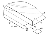
本発明の実施形態の幅木梱包品であって、梱包箱から幅木を引き出した状態を示す斜視図である。It is a skirting board package of embodiment of this invention, Comprising: It is a perspective view which shows the state which pulled out the skirting board from the packing box. 同上のパッド及びこれに巻きつけた幅木を示す斜視図である。It is a perspective view which shows a pad same as the above and a skirting board wound around this. 同上の幅木の側面図である。It is a side view of a baseboard same as the above. 同上の梱包箱の展開図である。It is an expanded view of a packaging box same as the above. (a)は同上の支持片の側面図であり、(b)は同上の支持片の展開図である。(A) is a side view of a support piece same as the above, and (b) is a development view of the support piece same as the above. 同上の幅木の施工状態を示す断面図である。It is sectional drawing which shows the construction state of a baseboard same as the above. 同上の梱包箱に引出口を形成する様子を示した斜視図である。It is the perspective view which showed a mode that the drawer outlet was formed in a packaging box same as the above. 同上の引出口を形成する前の梱包箱の斜視図である。It is a perspective view of the packaging box before forming the same outlet. 同上の幅木が施工される壁に接着剤を塗布する様子を示した斜視図である。It is the perspective view which showed a mode that an adhesive agent was apply | coated to the wall where a base board same as the above is constructed. 同上の幅木を壁に施工する様子を示した斜視図である。It is the perspective view which showed a mode that the base board same as the above was constructed to a wall. 入隅用の接続具を示し、(a)は表面側から見た斜視図であり、(b)は裏面側から見た斜視図である。The connection tool for corners is shown, (a) is the perspective view seen from the surface side, (b) is the perspective view seen from the back side. 出隅用の接続具を示し、(a)は表面側から見た斜視図であり、(b)は裏面側から見た斜視図である。The connection tool for a corner is shown, (a) is the perspective view seen from the surface side, (b) is the perspective view seen from the back surface side. 同上の幅木を入隅用の接続具で接続して施工した状態を示す斜視図である。It is a perspective view which shows the state which connected and constructed the base board same as the above with the connection tool for corners. 同上の幅木を出隅用の接続具で接続して施工した状態を示す斜視図である。It is a perspective view which shows the state which connected and constructed the base board same as the above with the connector for a corner. 同上の幅木を入隅用の接続具で接続して施工した状態を示す水平断面図である。It is a horizontal sectional view which shows the state which connected and constructed the base board same as the above with the connection tool for entering corners. 他例の幅木を示す側面図である。It is a side view which shows the baseboard of another example. 他例のパッドに幅木を巻き付けた様子を示す平面図である。It is a top view which shows a mode that the baseboard was wound around the pad of another example.

以下、本発明を添付図面に基づいて説明する。図1に示されるように本実施形態の幅木梱包品1は、幅木2、パッド3、及び梱包箱4を備えている。幅木2はパッド3にロール状に巻き取られた状態でパッド3と共に梱包箱4に収納される。   Hereinafter, the present invention will be described with reference to the accompanying drawings. As shown in FIG. 1, a baseboard package 1 according to this embodiment includes a baseboard 2, a pad 3, and a packing box 4. The skirting board 2 is housed in a packing box 4 together with the pad 3 while being wound around the pad 3 in a roll shape.

図3には幅木2の側面図が示されている。幅木2は押出成形品であって、帯状の本体部20と、本体部20から下側に向けて突出したひれ状部21を備えている。幅木2の本体部20は厚さが5mm以下であり、その本体部20は湾曲変形可能で且つ切断可能な合成樹脂で構成されている。具体的には、幅木2として、曲げ弾性率が1400MPa以上、1600MPa以下のいわゆる半硬質のものが用いられる。   FIG. 3 shows a side view of the skirting board 2. The skirting board 2 is an extrusion-molded product, and includes a strip-shaped main body portion 20 and a fin-shaped portion 21 protruding downward from the main body portion 20. The main body 20 of the skirting board 2 has a thickness of 5 mm or less, and the main body 20 is made of a synthetic resin that can be bent and cut. Specifically, a so-called semi-rigid one having a flexural modulus of 1400 MPa or more and 1600 MPa or less is used as the skirting board 2.

本体部20の材料としては、ポリプロピレン、ABS(acrylonitrilebutadiene styrene)、EVA(Ethylence-Vinyl Acetate)、塩化ビニル等が用いられる。幅木2のひれ状部21は本体部20よりも軟らかい材料によって形成される。ひれ状部21の材料としては、例えばオレフィン系エラストマー(TPO)等の軟質の材料が用いられる。   As the material of the main body 20, polypropylene, ABS (acrylonitrile butadiene styrene), EVA (Ethylence-Vinyl Acetate), vinyl chloride, or the like is used. The fin-like portion 21 of the skirting board 2 is formed of a softer material than the main body portion 20. As the material of the fin-like portion 21, for example, a soft material such as olefin elastomer (TPO) is used.

本体部20の表面(前面)の上部には、本体部20の長手方向と平行な凹溝200が本体部20の長手方向に亘って形成されている。凹溝200は溝深さが1mm以下、開口幅が2mm以下に設定されており、表面側から見たときに目立ち難くなっている。   A concave groove 200 parallel to the longitudinal direction of the main body 20 is formed in the upper part of the surface (front surface) of the main body 20 over the longitudinal direction of the main body 20. The concave groove 200 is set to have a groove depth of 1 mm or less and an opening width of 2 mm or less, and is difficult to stand out when viewed from the surface side.

凹溝200の上側の溝側面は本体部20の幅方向(上下方向)と直交している。凹溝200の下側の溝側面は溝奥側に行く程上方に位置するように傾斜したガイド面201となっている。凹溝200の底部を構成する奥面は本体部20の厚み方向と直交し、本体部20の表面と平行である。すなわち、凹溝200は溝奥側(後側)程溝幅が小さくなる断面台形状に凹んでいる。   The upper groove side surface of the concave groove 200 is orthogonal to the width direction (vertical direction) of the main body portion 20. The groove side surface on the lower side of the recessed groove 200 is a guide surface 201 that is inclined so as to be positioned upward as it goes to the groove back side. The back surface constituting the bottom of the groove 200 is orthogonal to the thickness direction of the main body 20 and is parallel to the surface of the main body 20. That is, the recessed groove 200 is recessed in a trapezoidal shape with a groove width that becomes smaller toward the back side (back side) of the groove.

本体部20の裏面(後面)の下部には後方に開口する凹部202が形成されている。凹部202は本体部20の長手方向に亘って形成された溝であって、断面矩形状に凹んでいる。凹部202の溝幅は凹溝200の溝幅よりも大きくなっている。   A recess 202 is formed in the lower part of the back surface (rear surface) of the main body 20 and opens rearward. The recess 202 is a groove formed over the longitudinal direction of the main body 20 and is recessed in a rectangular cross section. The groove width of the recess 202 is larger than the groove width of the recess 200.

本体部20の上端面の裏面側端部は裏面側に行く程下方に位置するように傾斜した傾斜面203となっている。すなわち、本体部20の裏面と上端面とでなす隅部はC面取り状に形成されている。本体部20の表面と上端面とでなす隅部はR面取り状に形成されており、本体部20の表面と下端面とでなす隅部はC面取り状に形成されている。また、図示は省略するが、本体部20の表面にはトップコート層が形成されている。また、本体部20の裏面にはプライマー塗料が塗布されてプライマー層が形成される。なお、トップコート層やプライマー層は省略可能である。   A rear surface side end portion of the upper end surface of the main body portion 20 is an inclined surface 203 which is inclined so as to be positioned downward as it goes to the rear surface side. That is, the corner formed by the back surface and the upper end surface of the main body portion 20 is formed in a C chamfer shape. A corner portion formed by the surface and the upper end surface of the main body portion 20 is formed in an R chamfer shape, and a corner portion formed by the surface and the lower end surface of the main body portion 20 is formed in a C chamfer shape. Although not shown, a top coat layer is formed on the surface of the main body 20. Further, a primer coating is applied to the back surface of the main body portion 20 to form a primer layer. The top coat layer and primer layer can be omitted.

ひれ状部21は本体部20の長手方向に亘って形成されている。ひれ状部21は本体部20の下端面から下側に向けて突出している。ひれ状部21の厚み(前後幅)は下側に行く程小さくなっており、その下端部は尖っている。ひれ状部21は下方に行くにつれて後方に位置するように湾曲している。   The fin-shaped portion 21 is formed along the longitudinal direction of the main body portion 20. The fin-like portion 21 protrudes downward from the lower end surface of the main body portion 20. The thickness (front-rear width) of the fin-shaped portion 21 decreases toward the lower side, and the lower end portion thereof is pointed. The fin-shaped portion 21 is curved so as to be located rearward as it goes downward.

帯状の幅木2を巻き付けるためのパッド3は、図5(a)に示される帯状の支持片30を複数有している。本実施形態のパッド3は3つの支持片30で構成されている。各支持片30は、図5(b)に示される帯状の段ボール材を幅方向の中心で二つ折りすることで形成される。図5(a)に示されるように各支持片30の長手方向の一端部には第一切溝300が形成され、他端部には第二切溝301が形成されている。両切溝300、301は共に支持片30の幅方向外側に向けて開口するが、その開口方向は逆方向である。パッド3の隣り合う支持片30は、一方の支持片30の長手方向において第一切溝300に対応する部分を、他方の支持片30の第二切溝301に差し込むことで連結される。図2に示されるように各支持片30の長手方向の両端部は同一円周上に位置し、パッド3に巻き取られた幅木2を内側から支持する支持部302を構成する。   The pad 3 for winding the belt-like baseboard 2 has a plurality of belt-like support pieces 30 shown in FIG. The pad 3 of this embodiment is composed of three support pieces 30. Each support piece 30 is formed by folding the strip-shaped cardboard material shown in FIG. 5B in half at the center in the width direction. As shown in FIG. 5A, a first groove 300 is formed at one end of each support piece 30 in the longitudinal direction, and a second kerf 301 is formed at the other end. Both the cut grooves 300 and 301 are opened toward the outer side in the width direction of the support piece 30, but the opening direction is opposite. The adjacent support pieces 30 of the pad 3 are connected by inserting a portion corresponding to the first groove 300 in the longitudinal direction of one support piece 30 into the second cut groove 301 of the other support piece 30. As shown in FIG. 2, both ends in the longitudinal direction of each support piece 30 are located on the same circumference, and constitute a support portion 302 that supports the baseboard 2 wound around the pad 3 from the inside.

幅木2は凹溝200が形成された表面をパッド3の外側に向けた状態でパッド3に巻き取られる。幅木2は例えばその内径寸法が800mm以上1000mm以下の範囲内に収まるように連続して20m程度パッド3に巻き取られ、パッド3の周囲に複数回周回している。本実施形態の幅木2はその内径寸法が900mmとなるようにパッド3に巻き取られている。   The skirting board 2 is wound around the pad 3 with the surface on which the concave groove 200 is formed facing the outside of the pad 3. The skirting board 2 is continuously wound around the pad 3 by about 20 m so that the inner diameter thereof falls within the range of 800 mm or more and 1000 mm or less, and wraps around the pad 3 a plurality of times. The skirting board 2 of this embodiment is wound around the pad 3 so that the inner diameter dimension thereof is 900 mm.

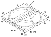
梱包箱4は段ボール製で扁平な正方形箱状に形成されている。図4には梱包箱4を展開した状態が示されている。梱包箱4は、天面を構成する上面板部40、底面を構成する2つの下面板部41、端面を構成する四つの端面板部42、及び、2つの差込板部43を有している。   The packing box 4 is made of corrugated cardboard and is formed in a flat square box shape. FIG. 4 shows a state where the packing box 4 is unfolded. The packaging box 4 includes an upper surface plate portion 40 that constitutes the top surface, two lower surface plate portions 41 that constitute the bottom surface, four end surface plate portions 42 that constitute the end surfaces, and two insertion plate portions 43. Yes.

矩形状の上面板部40の各辺には端面板部42が接続されている。以下、特に区別する場合には、端面板部42のうち、箱状に組み立てたときに対向する一対の端面板部42を端面板部420とし、他の一対の端面板部42を端面板部421とする。各端面板部420の上面板部40と反対側の辺には下面板部41が接続されている。各端面板部421の上面板部40と反対側の辺には差込板部43が接続されている。   An end face plate portion 42 is connected to each side of the rectangular upper surface plate portion 40. Hereinafter, when particularly distinguishing, among the end face plate portions 42, the pair of end face plate portions 42 that face each other when assembled in a box shape are referred to as end face plate portions 420, and the other pair of end face plate portions 42 are end face plate portions. 421. A bottom plate 41 is connected to the side of each end plate 420 opposite to the top plate 40. An insertion plate portion 43 is connected to a side of each end surface plate portion 421 opposite to the upper surface plate portion 40.

梱包箱4は、矩形状の上面板部40の各辺、各端面板部420と下面板部41の間の境界、及び、各端面板部421と差込板部43の間の境界が直角に折り曲げられることで、箱状に組み立てられる。梱包箱4を箱状にしたとき、各差込板部43は両下面板部41の上面側に差し込まれる。図8に示されるように梱包箱4の両下面板部41の端部同士は突き合わされ、両者は両下面板部41に跨って貼り付けられた第一の粘着テープ44によって接合される。また、各端面板部421と両下面板部41の端部同士も第二の粘着テープ45を用いて接合される。粘着テープ44、45としては例えばポリプロピレンテープが用いられる。   In the packing box 4, each side of the rectangular upper surface plate portion 40, a boundary between each end surface plate portion 420 and the lower surface plate portion 41, and a boundary between each end surface plate portion 421 and the insertion plate portion 43 are perpendicular to each other. It is assembled into a box shape by being folded into two. When the packaging box 4 is made into a box shape, each insertion plate portion 43 is inserted into the upper surface side of both lower surface plate portions 41. As shown in FIG. 8, the ends of the both lower surface plate portions 41 of the packaging box 4 are abutted with each other, and both are joined by a first adhesive tape 44 that is pasted across the both lower surface plate portions 41. Further, the end portions of each end face plate portion 421 and both lower face plate portions 41 are also joined using the second adhesive tape 45. For example, polypropylene tape is used as the adhesive tapes 44 and 45.

図8に示されるように箱状をなした梱包箱4には、パッド3及びこれに巻き取られた幅木2が収納される。この収納状態では、幅木2の幅方向が扁平な梱包箱4の厚み方向と平行になる。また、ひれ状部21が梱包箱4の下面板部41側に向けた状態とされる。正方形状の梱包箱4の各辺の長さは、パッド3に巻き取られた幅木2の外径と略同じ寸法とされる。このため、梱包箱4にパッド3に巻き取られた幅木2を収納したとき、幅木2の外周面が梱包箱4の四方の端面板部42に近接し、これら端面板部42によって幅木2を外側から支持することができる。ここで、「近接」とは近傍に配置された状態又は当接された状態のいずれかの状態にあることを意味する。   As shown in FIG. 8, a pad 3 and a baseboard 2 wound around the pad 3 are stored in a box 4 in a box shape. In this stored state, the width direction of the skirting board 2 is parallel to the thickness direction of the flat packing box 4. Further, the fin-shaped portion 21 is in a state directed toward the lower surface plate portion 41 side of the packaging box 4. The length of each side of the square packing box 4 is approximately the same as the outer diameter of the skirting board 2 wound around the pad 3. For this reason, when the skirting board 2 wound up by the pad 3 is stored in the packing box 4, the outer peripheral surface of the skirting board 2 comes close to the four end face plate portions 42 of the packing box 4, and the end face plate portions 42 make a width. The tree 2 can be supported from the outside. Here, “adjacent” means being in a state of being arranged in the vicinity or in a state of being in contact with each other.

正方形状の梱包箱4の角部には、梱包箱4内にパッド3に巻き取られた状態で収納された幅木2を引き出すための引出口46が形成される。引出口46は図7に示されるように梱包箱4の端面板部421の長手方向の端部を切除することによって形成される。図8に示されるように引出口46を形成する前の梱包箱4は、各端面板部421の長手方向の端部で構成された矩形状の切除部422を有している。各切除部422は端面板部421の幅方向に亘っている。図4に示されるように各切除部422の周囲、すなわち、端面板部421の他の部分との境界、上面板部40との境界、及び差込板部43との境界には、ミシン目47が設けられている。そして、図7に示されるように切除部422の周囲にあるミシン目47を切断して任意の切除部422を切除することで、該切除部422が切除された部分を引出口46とすることができる。このように引出口46を梱包箱4の一部を切除して形成することで、利用前においては図8に示されるように引出口46が形成される部分を切除部422で閉塞することができ、梱包箱4内にごみや埃等が入り込み難くなる。   In the corner portion of the square packing box 4, an outlet 46 is formed for pulling out the skirting board 2 stored in the packing box 4 while being wound around the pad 3. As shown in FIG. 7, the outlet 46 is formed by cutting off the end portion in the longitudinal direction of the end face plate portion 421 of the packaging box 4. As shown in FIG. 8, the packaging box 4 before forming the outlet 46 has a rectangular cutout 422 formed by the end portions of the end face plate portions 421 in the longitudinal direction. Each cut portion 422 extends in the width direction of the end face plate portion 421. As shown in FIG. 4, perforations are formed around each cut portion 422, that is, at the boundary with the other portion of the end face plate portion 421, the boundary with the upper surface plate portion 40, and the boundary with the insertion plate portion 43. 47 is provided. Then, as shown in FIG. 7, by cutting the perforation 47 around the excision part 422 and excising the optional excision part 422, the part where the excision part 422 is excised is used as the outlet 46. Can do. Thus, by forming the outlet 46 by cutting a part of the packaging box 4, before use, the portion where the outlet 46 is formed can be blocked by the cutting part 422 as shown in FIG. 8. This makes it difficult for dust and dirt to enter the packing box 4.

梱包箱4内のパッド3に巻き取られた幅木2は、図1に示されるように引出口46に対向する外周部から引出口46を通して梱包箱4の外部へと導出することができる。また、このように引出口46から導出された幅木2の端部を作業者が引っ張ることで、パッド3及びこれに巻き取られた幅木2を梱包箱4内で回動させながら、この幅木2を引出口46から梱包箱4の外に引き出すことができる。梱包箱4内の幅木2及びパッド3は、梱包箱4の四方の端面板部42で外側へ移動することが規制され、また、梱包箱4の上面板部40及び下面板部41で上下方向の移動が規制される。このため、梱包箱4から幅木2を引き出すときには、パッド3及びこれに巻き取られた幅木2を梱包箱4内でスムーズに回動させることができる。   The skirting board 2 wound up by the pad 3 in the packaging box 4 can be led out of the packaging box 4 through the outlet 46 from the outer peripheral portion facing the outlet 46 as shown in FIG. Further, the operator pulls the end of the baseboard 2 led out from the outlet 46 in this way, so that the pad 3 and the baseboard 2 wound around the pad 3 are rotated in the packing box 4 while The skirting board 2 can be pulled out of the packing box 4 from the outlet 46. The skirting board 2 and the pad 3 in the packing box 4 are restricted from moving outward by the four end face plate portions 42 of the packing box 4, and are moved up and down by the upper surface plate portion 40 and the lower surface plate portion 41 of the packing box 4. Directional movement is restricted. For this reason, when pulling out the skirting board 2 from the packing box 4, the pad 3 and the skirting board 2 wound around the pad 3 can be smoothly rotated in the packing box 4.

作業者は梱包箱4に梱包された幅木2を例えば以下のように建物の壁5に施工する。まず、作業者は、図9に示されるように壁5において幅木2を取り付ける箇所に接着剤50を塗布する。この壁5は壁下地51(図6参照)に壁紙52(図6参照)が貼り付けられたものであってもよいし、壁紙52が貼り付けられる前の壁下地51であってもよい。以下では、壁紙52が貼り付けられる前の壁下地51に幅木2を施工する例につき説明する。幅木2を壁5に接着する接着剤50としては例えば変性酢酸ビニル系接着剤が用いられる。接着剤50は壁5において床6から上方に少し離れた幅木2の上部に対応する部分にのみ塗布される。   An operator constructs the skirting board 2 packed in the packing box 4 on the wall 5 of the building as follows, for example. First, as shown in FIG. 9, the worker applies an adhesive 50 to a location where the baseboard 2 is attached on the wall 5. The wall 5 may be a wall base 51 (see FIG. 6) pasted with a wallpaper 52 (see FIG. 6), or may be a wall base 51 before the wallpaper 52 is pasted. Below, the example which constructs the baseboard 2 in the wall base 51 before the wallpaper 52 is affixed is demonstrated. As the adhesive 50 for adhering the skirting board 2 to the wall 5, for example, a modified vinyl acetate adhesive is used. The adhesive 50 is applied only to a portion of the wall 5 corresponding to the upper portion of the baseboard 2 that is slightly away from the floor 6.

次に作業者は図10に示されるようにパッド3に巻き取られた状態で梱包箱4内に収納された幅木2を引出口46から引き出しながら、幅木2の裏面の上部を接着剤50を介して壁5に貼り付けていく。また、この際、壁5に貼り付けられた幅木2の凹溝200の底部に長手方向に間隔を介して固着具7を順次打ち込み、これによって幅木2を壁5に固定していく。   Next, as shown in FIG. 10, the operator pulls out the skirting board 2 accommodated in the packing box 4 while being wound around the pad 3 from the outlet 46, and then attaches the upper part of the back surface of the skirting board 2 to the adhesive. Affix to the wall 5 through 50. At this time, the fixing tool 7 is sequentially driven into the bottom portion of the concave groove 200 of the base board 2 attached to the wall 5 with a space in the longitudinal direction, thereby fixing the base board 2 to the wall 5.

固着具7としてはピンネイル70が用いられる。なお、固着具7としては、施工後における外観を良くするため、頭部を有するフィニッシュネイルを用いず、頭部の無いピンネイル70のみを用いるのがよい。ピンネイル70を打ち込む作業は、ピンネイラーと呼ばれるピン打機を用いて行われる。すなわち、ピン打機を用いて凹溝200の底部にピンネイル70を打つ込むには、作業者はピン打機の先端部を本体部20の表面側から凹溝200の底部に向け、ピン打機を操作してピン打機の先端部からピンネイル70を打ち出す。このように打ち出されたピンネイル70は本体部20を通して壁5に打ち込まれる。これにより幅木2は壁5に固定され、接着剤50が硬化する前において壁5から剥がれ難くなる。ピンネイル70は凹溝200の底部から前方に突出しないように本体部20に打ち込まれる。ここで、ピン打機を用いて凹溝200の底部にピンネイル70を打ち込むとき、ピン打機の先端部の向きが多少ずれたとしても、ピン打機から打ち出されたピンネイル70を凹溝200の傾斜したガイド面201で凹溝200の底部側に導くことができる。このため、凹溝200の底部に確実にピンネイル70を打ち込むことができる。   A pin nail 70 is used as the fixing tool 7. In addition, as the fixing tool 7, in order to improve the external appearance after the construction, it is preferable to use only the pin nail 70 having no head instead of the finish nail having the head. The operation of driving the pin nail 70 is performed using a pin driver called a pin nailer. That is, in order to drive the pin nail 70 into the bottom of the concave groove 200 using a pin hammer, the operator points the tip of the pin hammer from the surface side of the main body 20 toward the bottom of the concave groove 200, and the pin hammer Is operated to drive out the pin nail 70 from the tip of the pinning machine. The pin nail 70 thus punched out is driven into the wall 5 through the main body 20. As a result, the skirting board 2 is fixed to the wall 5 and hardly peels off from the wall 5 before the adhesive 50 is cured. The pin nail 70 is driven into the main body 20 so as not to protrude forward from the bottom of the concave groove 200. Here, when the pin nail 70 is driven into the bottom of the concave groove 200 using a pin hammer, even if the direction of the tip of the pin hammer is slightly deviated, the pin nail 70 punched out from the pin hammer is inserted into the concave groove 200. The inclined guide surface 201 can guide the groove 200 to the bottom side. For this reason, the pin nail 70 can be reliably driven into the bottom of the concave groove 200.

また、幅木2は図6に示されるようにひれ状部21の下端部を床6に押し付けた状態で壁5に固定される。このため、ひれ状部21の弾性変形により床6の不陸を吸収して、幅木2を長手方向を水平にした状態で壁5に固定することができる。   Further, as shown in FIG. 6, the skirting board 2 is fixed to the wall 5 in a state where the lower end portion of the fin-like portion 21 is pressed against the floor 6. For this reason, the unevenness of the floor 6 can be absorbed by the elastic deformation of the fin-shaped portion 21, and the skirting board 2 can be fixed to the wall 5 in a state where the longitudinal direction is horizontal.

また、幅木2は梱包箱4の底面部を下に向けた状態で梱包箱4から引き出される。このようにすることで、梱包箱4内の幅木2を施工状態と同様にひれ状部21を下に向けた状態で引き出すことができる。このため、幅木2を壁5に貼り付けるにあたって幅木2の向きを変更する手間を省くことができる。   The skirting board 2 is pulled out from the packaging box 4 with the bottom surface of the packaging box 4 facing downward. By doing in this way, the skirting board 2 in the packing box 4 can be pulled out in a state where the fin-like portion 21 is directed downward as in the construction state. For this reason, it is possible to save the trouble of changing the direction of the baseboard 2 when the baseboard 2 is attached to the wall 5.

前記幅木2の接着剤50及び固着具7を用いた壁5への施工は、壁5の端部付近又は隅部付近に至るまで行われる。次に作業者は、幅木2の壁5の端部や隅部に対応する箇所、例えば図10において二点鎖線で示される箇所を、電気丸のこや、手のこ、はさみ、カッターナイフ等の切断具を用いて切断する。そして、この幅木2の切断側部分を前記同様接着剤50及び固着具7を用いて壁5に固定する。これにより、幅木2は壁5に取り付けられる。   Construction on the wall 5 using the adhesive 50 and the fixing tool 7 of the skirting board 2 is performed up to the vicinity of the end portion or the corner portion of the wall 5. Next, the operator selects an electric circle saw, a hand saw, scissors, a cutter knife at a location corresponding to the end or corner of the wall 5 of the skirting board 2, for example, a location indicated by a two-dot chain line in FIG. Cut using a cutting tool. And the cutting | disconnection side part of this baseboard 2 is fixed to the wall 5 using the adhesive agent 50 and the fixing tool 7 like the above. Thereby, the skirting board 2 is attached to the wall 5.

幅木2の施工後には、幅木2の上方の壁下地51に図6に示される壁紙52が貼り付けられる。この壁紙52の下端縁は、例えばカッターナイフを幅木2の傾斜面203に沿わせながら幅木2の長手方向に移動させることで、傾斜面203の下縁部に沿って切断される。また、壁5(詳しくは壁紙52の下縁部)と傾斜面203との間には上方に開口する断面三角形状の隙間53が形成されるが、この隙間53には壁紙52の下縁部の浮き上がりを防止するためコーキング材54が充填される。   After the construction of the skirting board 2, the wallpaper 52 shown in FIG. 6 is pasted on the wall base 51 above the skirting board 2. The lower end edge of the wallpaper 52 is cut along the lower edge of the inclined surface 203 by moving the cutter knife along the inclined surface 203 of the skirting board 2 in the longitudinal direction of the skirting board 2, for example. Further, a gap 53 having a triangular cross section that opens upward is formed between the wall 5 (specifically, the lower edge of the wallpaper 52) and the inclined surface 203. The lower edge of the wallpaper 52 is formed in the gap 53. The caulking material 54 is filled in order to prevent the floating.

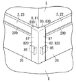
また、隅部を有する壁5に幅木2を施工する場合、幅木2を壁5の隅部に沿って直角に屈曲させることが困難となる。このため、隅部を有する壁5に幅木2を施工する場合、図13や図14に示されるように隅部を挟んだ両側の壁5の夫々に別の幅木2を施工するのがよい。ここで、本実施形態の幅木2は、図13や図14に示されるように、隅部を介して隣接する他の幅木2に接続具8を介して仕舞い良く接続できるようになっている。   Further, when the baseboard 2 is constructed on the wall 5 having the corner, it is difficult to bend the baseboard 2 along the corner of the wall 5 at a right angle. For this reason, when the baseboard 2 is constructed on the wall 5 having the corner, as shown in FIG. 13 and FIG. 14, another baseboard 2 is constructed on each of the walls 5 on both sides sandwiching the corner. Good. Here, as shown in FIG. 13 and FIG. 14, the skirting board 2 of the present embodiment can be connected to the other skirting boards 2 adjacent to each other through the corners through the connection tool 8. Yes.

接続具8は幅木2よりも曲げ弾性率が大きく、曲がり難い硬質な材料で形成されている。この接続具8としては、図11に示される入隅用の接続具80と、図12に示される出隅用の接続具81の二種類がある。接続具80、81は、共に、カバー片部82、上片部83、連結片部84、及び突片部85を有している。   The connection tool 8 is formed of a hard material having a bending elastic modulus larger than that of the skirting board 2 and difficult to bend. As this connection tool 8, there are two types of connection tool 80 for entry corner shown in FIG. 11 and connection tool 81 for exit corner shown in FIG. Each of the connecting tools 80 and 81 has a cover piece portion 82, an upper piece portion 83, a connecting piece portion 84, and a protruding piece portion 85.

接続具80、81のカバー片部82は縦長であって水平断面L字状に形成されている。図11に示されるように入隅用の接続具80のカバー片部82はその表面側に平面視で直角の角部が形成されている。図12に示されるように出隅用の接続具81のカバー片部82はその裏面側に平面視で直角の角部が形成されている。接続具80、81のカバー片部82は直角に接続された両側の縦片部820で構成されている。   The cover piece portions 82 of the connection tools 80 and 81 are vertically long and are formed in an L-shaped horizontal section. As shown in FIG. 11, the cover piece portion 82 of the connecting tool 80 for the corner is formed with a right-angled corner portion in a plan view on the surface side. As shown in FIG. 12, the cover piece portion 82 of the connecting tool 81 for the corner is formed with a right-angled corner portion in plan view on the back surface side. The cover piece part 82 of the connection tools 80 and 81 is comprised by the vertical piece part 820 of the both sides connected at right angle.

接続具80、81の上片部83はカバー片部82の上縁から裏面側に向けて突出している。接続具80、81の上片部83は直角に接続された両側の横片部830で構成されており、平面視でカバー片部82に沿うL字状に形成されている。カバー片部82及び上片部83を設けることで、接続具80、81の両側には縦片部820とこれに接続された横片部830とで構成された被嵌部87が夫々形成される。   The upper piece 83 of the connection tools 80 and 81 protrudes from the upper edge of the cover piece 82 toward the back side. The upper piece part 83 of the connection tools 80 and 81 is composed of lateral piece parts 830 on both sides connected at right angles, and is formed in an L shape along the cover piece part 82 in plan view. By providing the cover piece portion 82 and the upper piece portion 83, fitted portions 87 each formed of a vertical piece portion 820 and a horizontal piece portion 830 connected thereto are formed on both sides of the connecting devices 80 and 81, respectively. The

接続具80、81の連結片部84はカバー片部82の両側の縦片部820に夫々設けられている。各連結片部84は縦片部820の下部から裏面側に向かって突出している。各接続具80の突片部85は各連結片部84に設けられている。各突片部85は連結片部84の裏面側端部からカバー片部82の外側方に向かって突出しており、対応する縦片部820と平行である。各突片部85は対応する縦片部820の表面側から見たときに縦片部820よりも外側方に突出している。各突片部85と対応する縦片部820の間には外側方に開口する嵌込溝86が形成されている。   The connecting piece portions 84 of the connection tools 80 and 81 are respectively provided on the vertical piece portions 820 on both sides of the cover piece portion 82. Each connecting piece 84 protrudes from the lower part of the vertical piece 820 toward the back side. The projecting piece 85 of each connector 80 is provided on each connecting piece 84. Each protruding piece 85 protrudes from the back side end of the connecting piece 84 toward the outside of the cover piece 82 and is parallel to the corresponding vertical piece 820. Each protruding piece 85 protrudes outward from the vertical piece 820 when viewed from the surface side of the corresponding vertical piece 820. A fitting groove 86 that opens outward is formed between each protruding piece 85 and the corresponding vertical piece 820.

作業者は接続具8を用いて幅木2の端部同士を接続する場合、例えば以下の施工を行う。なお、以下では入隅用の接続具80を用いる例について説明するが、出隅用の接続具81を用いる場合も同様である。また、以下では前述のように壁5に対して接着剤50及びピンネイル70を用いて固定された第一の幅木2の終端部(切断側端部)に、隅部を介して隣接する第二の幅木23の始端部を接続する例につき説明する。以下、特に区別する場合には、第一の幅木22、第二の幅木23と記載する。   When an operator connects the edge parts of the baseboard 2 using the connection tool 8, for example, the following construction is performed. In the following, an example in which the connecting tool 80 for the corner is used will be described, but the same applies to the case where the connector 81 for the corner is used. In the following description, the first end of the first skirting board 2 that is fixed to the wall 5 using the adhesive 50 and the pin nail 70 as described above (the end on the cutting side) is adjacent to the first end through the corner. An example of connecting the start ends of the second baseboard 23 will be described. Hereinafter, in particular, the first baseboard 22 and the second baseboard 23 will be described.

まず、接続具80を第一の幅木22の終端部と第二の幅木23の始端部に取り付ける。なお、第一の幅木22は前述のように隅部付近までの部位が接着剤50及び固着具7を用いて壁5に固定された状態でその切断側端部である終端部が接続具8に取り付けられる。すなわち、第一の幅木22は隅部付近まで接着剤50及び固着具7を用いて固定された後、切断具によって壁5の隅部に対応する位置で切断され、この切断側端部が接続具8に取り付けられる。また、第二の幅木23は梱包箱4の引出口46から引き出される幅木2である。例えば第二の幅木23としては第一の幅木22を切断した後に梱包箱4に残る幅木2が用いられる。すなわち、この場合、梱包箱4に残る幅木2の切断側端部が接続具8に取り付けられる。   First, the connection tool 80 is attached to the terminal end of the first baseboard 22 and the start end of the second baseboard 23. As described above, the first skirting board 22 is fixed to the wall 5 by using the adhesive 50 and the fixing tool 7 and the terminal part of the first base board 22 is connected to the connecting part. 8 is attached. That is, the first skirting board 22 is fixed to the vicinity of the corner using the adhesive 50 and the fixing tool 7, and then cut by the cutting tool at a position corresponding to the corner of the wall 5. It is attached to the connection tool 8. The second skirting board 23 is the skirting board 2 drawn out from the outlet 46 of the packaging box 4. For example, the baseboard 2 that remains in the packaging box 4 after the first baseboard 22 is cut is used as the second baseboard 23. That is, in this case, the cut-side end portion of the skirting board 2 remaining in the packing box 4 is attached to the connector 8.

第一の幅木22を接続具80に取り付けるには、作業者は予め接続具80の対応する縦片部820の裏面、対応する横片部830の下面、及び対応する突片部85の表面に接着剤を塗布しておく。次に作業者は接続具80の一方の被嵌部87に第一の幅木22の終端部を外側方から挿入する。これにより、当該被嵌部87によって第一の幅木22の終端部が被嵌される。また、これにより、接続具8の一方の縦片部820の裏面は同面に塗布された接着剤を介して第一の幅木22の終端部の表面に接着される。また、接続具8の一方の横片部830の下面は同面に塗布された接着剤を介して第一の幅木22の終端部の上端面に接着される。また、第一の幅木22の終端部における凹部202に接続具8の一方の突片部85が嵌め込まれ、第一の幅木22の終端部の下部が接続具8の一方の嵌込溝86に外側方から嵌め込まれる。また、これにより、接続具80の一方の突片部85の表面が第一の幅木22の凹部202の奥面に接着剤を介して接着される。   In order to attach the first skirting board 22 to the connection tool 80, the operator previously has a back surface of the corresponding vertical piece portion 820 of the connection tool 80, a lower surface of the corresponding horizontal piece portion 830, and a surface of the corresponding protrusion piece portion 85. Apply an adhesive to Next, the operator inserts the end portion of the first baseboard 22 into the one fitting portion 87 of the connection tool 80 from the outside. As a result, the end portion of the first skirting board 22 is fitted by the fitted portion 87. Moreover, by this, the back surface of one vertical piece portion 820 of the connection tool 8 is bonded to the surface of the terminal end portion of the first skirting board 22 through the adhesive applied to the same surface. Moreover, the lower surface of one horizontal piece part 830 of the connection tool 8 is bonded to the upper end surface of the terminal end portion of the first skirting board 22 through an adhesive applied to the same surface. In addition, one protruding piece 85 of the connection tool 8 is fitted into the recess 202 at the terminal end of the first base plate 22, and the lower part of the terminal end of the first base plate 22 is one insertion groove of the connection tool 8. 86 is fitted from the outside. Thereby, the surface of one protrusion piece part 85 of the connection tool 80 is adhere | attached on the inner surface of the recessed part 202 of the 1st baseboard 22 via an adhesive agent.

第二の幅木23を接続具80に取り付けるには、作業者は予め接続具80の対応する縦片部820の裏面、対応する横片部830の下面、及び対応する突片部85の表面に接着剤を塗布しておく。次に接続具8の他方の被嵌部87に第二の幅木23の始端部を外側方から挿入する。これにより、当該被嵌部87によって第二の幅木23の始端部が被嵌される。また、これにより、接続具8の他方の縦片部820の裏面は同面に塗布された接着剤を介して第二の幅木23の始端部の表面に接着される。また、接続具8の他方の横片部830の下面は同面に塗布された接着剤を介して第二の幅木23の始端部の上端面に接着される。また、第二の幅木23の始端部における凹部202に接続具8の他方の突片部85が嵌め込まれ、第二の幅木23の始端部の下部が接続具8の他方の嵌込溝86に外側方から嵌め込まれる。また、これにより、接続具80の他方の突片部85の表面が同面に塗布された接着剤を介して第二の幅木23の凹部202の奥面に接着される。   In order to attach the second skirting board 23 to the connection tool 80, the operator previously has the back surface of the corresponding vertical piece portion 820 of the connection tool 80, the lower surface of the corresponding horizontal piece portion 830, and the surface of the corresponding protrusion piece portion 85. Apply an adhesive to Next, the starting end portion of the second skirting board 23 is inserted into the other fitted portion 87 of the connection tool 8 from the outside. Thereby, the start end part of the second skirting board 23 is fitted by the fitted part 87. Thereby, the back surface of the other vertical piece portion 820 of the connection tool 8 is bonded to the surface of the start end portion of the second skirting board 23 through the adhesive applied to the same surface. Further, the lower surface of the other horizontal piece portion 830 of the connector 8 is bonded to the upper end surface of the start end portion of the second skirting board 23 through an adhesive applied to the same surface. In addition, the other protruding piece 85 of the connecting tool 8 is fitted into the recess 202 at the starting end of the second skirting board 23, and the lower part of the starting end of the second skirting board 23 is the other fitting groove of the connecting tool 8. 86 is fitted from the outside. Thereby, the surface of the other projecting piece 85 of the connector 80 is bonded to the inner surface of the recess 202 of the second skirting board 23 via the adhesive applied to the same surface.

このように接続具80を第一の幅木22の終端部と第二の幅木23の始端部に取り付けた後、接続具80、第一の幅木22の終端部、第二の幅木22の始端部を図15に示されるように壁5の隅部に取り付ける。この取付けの前には、予め接続具80の両突片部85の裏面に接着剤を塗布しておく。また、壁5において第一の幅木22の終端部の上部に対応する部分、及び第二の幅木23の始端部の上部に対応する部分にも予め接着剤を塗布しておく。そして、作業者は第一の幅木22及び第二の幅木23が接続された接続具8を壁5の隅部に沿わせる。これにより、第一の幅木22の終端部の上部裏面及び第二の幅木23の始端部の上部裏面は、隅部を挟んだ両側の壁5に接着剤を介して接着される。また、接続具8の両突片部85の裏面も同面に塗布された接着剤を介して壁5に接着される。この後、作業者は第一の幅木22の終端部(接続具8で覆われていない部分)を凹溝200にピンネイル70を打ち込むことで壁5に固定し、また、第二の幅木23の始端部(接続具8で覆われていない部分)を凹溝200にピンネイル70を打ち込むことで壁5に固定する。   After attaching the connector 80 to the terminal end of the first baseboard 22 and the start end of the second baseboard 23 in this way, the connector 80, the terminal end of the first baseboard 22, and the second baseboard The starting end of 22 is attached to the corner of the wall 5 as shown in FIG. Prior to this attachment, an adhesive is applied in advance to the back surfaces of both projecting piece portions 85 of the connection tool 80. In addition, an adhesive is applied in advance to a portion of the wall 5 corresponding to the upper end portion of the first baseboard 22 and a portion corresponding to the upper end portion of the second baseboard 23. Then, the worker places the connecting tool 8 to which the first baseboard 22 and the second baseboard 23 are connected along the corner of the wall 5. Thereby, the upper back surface of the terminal part of the 1st baseboard 22 and the upper back surface of the start end part of the 2nd baseboard 23 are adhere | attached on the wall 5 of the both sides which pinched | interposed the corner part via an adhesive agent. Further, the back surfaces of both projecting piece portions 85 of the connector 8 are also bonded to the wall 5 via an adhesive applied to the same surface. Thereafter, the operator fixes the terminal end portion (the portion not covered with the connection tool 8) of the first skirting board 22 to the wall 5 by driving the pin nail 70 into the concave groove 200, and also the second skirting board. 23 is fixed to the wall 5 by driving a pin nail 70 into the concave groove 200 at a start end portion (a portion not covered with the connection tool 8).

なお、接続具80を用いた幅木2の施工は前記に限定されるものではない。例えば、第一の幅木22の終端部を接続具80に取り付け、この第一の幅木22を接続具80と共に壁5に取り付け、この後、接続具80に第二の幅木23の始端部を取り付け、この第二の幅木23を壁5に取り付けてもよい。   The construction of the skirting board 2 using the connection tool 80 is not limited to the above. For example, the terminal end of the first baseboard 22 is attached to the connection tool 80, the first baseboard 22 is attached to the wall 5 together with the connection tool 80, and then the start end of the second baseboard 23 is connected to the connection tool 80. The second skirting board 23 may be attached to the wall 5.

以上説明した本実施形態の幅木梱包品1は、湾曲変形可能で且つ切断可能な帯状の幅木2と、ロール状に巻いた幅木2を収納する梱包箱4を備えている。この構成により、ロール状に巻いた幅木2をその外側を梱包箱4によって支持した状態で梱包箱4に収納することができ、幅木2を小さくロール状にした状態で保管することができる。また、これにより幅木2の施工や持ち運びが容易になる。また、幅木2は梱包箱4に収納して汚れ難い状態で保管することができる。また、梱包箱4は梱包箱4に巻かれた状態で収納された幅木2を引き出すための引出口46を有している。このため、幅木2を施工する際には、梱包箱4に巻かれた状態で収納された幅木2を引出口46から引き出しながら壁5に取り付けることができ、施工が容易になる。   The baseboard package 1 of the present embodiment described above includes a belt-like baseboard 2 that can be bent and cut and a packaging box 4 that houses the baseboard 2 wound in a roll shape. With this configuration, the skirting board 2 wound in a roll shape can be stored in the packaging box 4 with the outside supported by the packaging box 4 and can be stored in a state where the skirting board 2 is made into a small roll shape. . This also facilitates the construction and carrying of the skirting board 2. Moreover, the skirting board 2 can be stored in the packing box 4 in a state that is difficult to get dirty. Further, the packing box 4 has an outlet 46 for pulling out the skirting board 2 stored in the state of being wound around the packing box 4. For this reason, when constructing the skirting board 2, the skirting board 2 stored in a state of being wound around the packing box 4 can be attached to the wall 5 while being pulled out from the outlet 46, and the construction becomes easy.

また、本実施形態では、曲げ弾性率が1400MPa以上1600MPa以下の幅木2を梱包箱4に収納することができる。   Moreover, in this embodiment, the baseboard 2 whose bending elastic modulus is 1400 MPa or more and 1600 MPa or less can be stored in the packing box 4.

また、本実施形態の幅木2は内径寸法が800mm以上1000mm以下として巻かれた状態で梱包箱4に収納される。このため、幅木2を巻き癖がつき難く且つコンパクトにした状態で梱包箱4に収納することができる。   Moreover, the baseboard 2 of this embodiment is accommodated in the packaging box 4 in the state wound by setting an internal diameter dimension to 800 mm or more and 1000 mm or less. For this reason, the skirting board 2 can be stored in the packaging box 4 in a state in which it is difficult to curl and is compact.

また、本実施形態の幅木梱包品1は幅木2が巻き取られるパッド3を備え、幅木2がパッド3に巻き取られた状態で梱包箱4に収納される。このため、巻かれた状態の幅木2をパッド3により内側から支持し、これにより幅木2をがたつき難い状態で梱包箱4に収納することができる。   Moreover, the baseboard package 1 of this embodiment is provided with the pad 3 by which the baseboard 2 is wound up, and the baseboard 2 is accommodated in the packaging box 4 in the state wound up by the pad 3. FIG. For this reason, the skirting board 2 in the wound state is supported from the inside by the pad 3, so that the skirting board 2 can be stored in the packing box 4 in a state in which it is difficult to rattle.

また、本実施形態の幅木2はその表面を外側に向けて巻かれた状態で梱包箱4に収納されるため、幅木2にはその裏面側に突となるような巻き癖がつき難くなる。このため、幅木2を壁5に沿わせた場合に幅木2の先に壁5に沿わせた部分が壁5から浮き上がり難くなる。すなわち、幅木2にはその表面側に突となるような巻き癖がつくが、幅木2の梱包箱4から引き出した直後の部分を壁5に沿わせた場合、幅木2の先に壁5に沿わせた部分が幅木2の巻き癖によって壁5を押圧するようになる。このため、幅木2の施工が容易になる。   Further, since the skirting board 2 of the present embodiment is stored in the packing box 4 with its surface wound outward, the skirting board 2 is unlikely to have a curl that protrudes on the back side. Become. For this reason, when the skirting board 2 is placed along the wall 5, the part of the skirting board 2 along the wall 5 is difficult to lift from the wall 5. In other words, the skirting board 2 has a curl that protrudes on the surface side, but when the part immediately after the skirting board 2 is pulled out from the packing box 4 is placed along the wall 5, the tip of the skirting board 2 The part along the wall 5 comes to press the wall 5 by the curl of the skirting board 2. For this reason, construction of the skirting board 2 becomes easy.

また、本実施形態の幅木2の施工方法にあっては、幅木2を梱包箱4の引出口46から引き出しながら壁5に接着することができる。このため、幅木2の施工が容易になる。   Moreover, in the construction method of the skirting board 2 of this embodiment, the skirting board 2 can be bonded to the wall 5 while being pulled out from the outlet 46 of the packing box 4. For this reason, construction of the skirting board 2 becomes easy.

また、本実施形態では壁5に接着された幅木2にピンネイル70を打ち込んで壁5に固着する。このため、壁5に接着された幅木2が接着剤50が硬化する前に壁5から浮き上がったり、剥がれたりすることを防止できる。   In the present embodiment, the pin nails 70 are driven into the baseboard 2 bonded to the wall 5 and fixed to the wall 5. For this reason, it is possible to prevent the skirting board 2 bonded to the wall 5 from being lifted off or peeled off from the wall 5 before the adhesive 50 is cured.

また、本実施形態では引出口46から引き出された幅木2を壁5の隅部又は端部に対応する部分で切断する。このため、施工する壁5の幅にかかわらず、幅木2を壁5の隅部又は端部に至るまで施工することができる。   In the present embodiment, the baseboard 2 drawn out from the outlet 46 is cut at a portion corresponding to the corner or end of the wall 5. For this reason, regardless of the width of the wall 5 to be constructed, the skirting board 2 can be constructed up to the corner or end of the wall 5.

なお、幅木2は接続具8を用いずに隅部を有する壁5に施工することも可能である。この場合は、例えば隅部を挟んで両側に位置する幅木2を切断端面が平面視で幅木2の厚み方向に対して45度傾斜するように切断し、この端面同士を突き合わせた状態で幅木2を壁5に取り付ければよい。   The skirting board 2 can be applied to the wall 5 having a corner without using the connection tool 8. In this case, for example, the baseboard 2 positioned on both sides across the corner is cut so that the cut end faces are inclined by 45 degrees with respect to the thickness direction of the baseboard 2 in plan view, and the end faces are in contact with each other. The skirting board 2 may be attached to the wall 5.

また、本実施形態の幅木2は曲げ弾性率が1400MPa以上、1600MPa以下のものであるが、幅木2の曲げ弾性率は前記の範囲を外れるものであってもよい。また、梱包箱4の形状は正方形に限定されるものではなく、正方形を除く長方形や円形、多角形に形成してもよい。   Moreover, although the base plate 2 of this embodiment has a bending elastic modulus of 1400 MPa or more and 1600 MPa or less, the bending elastic modulus of the base plate 2 may be out of the above range. Moreover, the shape of the packaging box 4 is not limited to a square, and may be formed in a rectangle, a circle, or a polygon excluding a square.

また、図2に示されるパッド3は各支持片30を直線状にしたものであるが、図17に示されるように各支持片30の支持部302となる両端部を折り曲げ、この折曲部分でパッド3に巻き取られた幅木2を内側から支持するようにしてもよい。このようにすると、パッド3から幅木2が引き出されて巻き取られた幅木2の内径寸法が大きくなったときに、支持片30の両端部の折曲部分の曲げ戻しによって、支持片30の両端部を巻き取られた幅木2の内側に接触するようにできる。このため幅木2の使用量にかかわらず各支持片30の両端部で巻き取られた幅木2の内側を常に支持することが可能となる。   Further, the pad 3 shown in FIG. 2 is formed by linearly supporting each support piece 30, but as shown in FIG. 17, both end portions to be the support portions 302 of each support piece 30 are bent, and this bent portion is The skirting board 2 wound around the pad 3 may be supported from the inside. In this case, when the inner diameter of the skirting board 2 drawn out from the pad 3 and wound up is increased, the supporting piece 30 is bent back by bending the bent portions at both ends of the supporting piece 30. Both end portions of the base plate 2 can be brought into contact with the inside of the skirting board 2 wound up. For this reason, it becomes possible to always support the inside of the baseboard 2 wound up at both ends of each support piece 30 regardless of the amount of baseboard 2 used.

なお、本実施形態では幅木2をパッド3に巻き付けた後に梱包箱4に収納するようにしたが、巻いた状態の幅木2を梱包箱4内に配置し、この幅木2の中心にパッド3を嵌め込んでも構わない。さらに、パッド3は本実施形態のものに限定されるものではない。例えば、パッド3は複数の支持片30を四角形以上の略多角形状をなすように連結することで形成してもよい。また、本実施形態のパッド3は同一円周上における6箇所の支持部302で幅木2の内側を支持するものであるが、同一円周上の三箇所以上(6箇所除く)の支持部で幅木2の内側を支持するものであってもよい。また、パッド3は幅木2を内側から支持する円形の外周面を有するものであってもよい。また、本実施形態ではパッド3にロール状に巻いた幅木2を梱包箱4に収納したが、パッド3を省略し、ロール状に巻いた幅木2を梱包箱4の四方の端面板部42で外側のみを支持した状態で梱包箱4に収納してもよい。   In this embodiment, the skirting board 2 is wound around the pad 3 and then stored in the packing box 4. However, the wound skirting board 2 is arranged in the packing box 4 and is placed at the center of the skirting board 2. The pad 3 may be inserted. Furthermore, the pad 3 is not limited to that of the present embodiment. For example, the pad 3 may be formed by connecting a plurality of support pieces 30 so as to form a substantially polygonal shape of a square or more. Further, the pad 3 of the present embodiment supports the inner side of the skirting board 2 with the six support portions 302 on the same circumference, but the support portions at three or more places (excluding six places) on the same circumference. The inside of the baseboard 2 may be supported. The pad 3 may have a circular outer peripheral surface that supports the baseboard 2 from the inside. Further, in the present embodiment, the baseboard 2 wound around the pad 3 in a roll shape is stored in the packaging box 4, but the pad 3 is omitted and the baseboard 2 wound around the roll is placed on the four end face plate portions of the packaging box 4. You may accommodate in the packaging box 4 in the state which supported only the outer side by 42.

また、本実施形態では凹溝200の下側の溝側面のみを傾斜させたが、図16に示されるように凹溝200の上側の溝側面を凹溝200の溝奥側に行く程下方に位置するように傾斜させてもよい。また、凹溝200の上側の溝側面のみを凹溝200の溝奥側に行く程下方に位置するように傾斜させてもよい。また、凹溝200の両溝側面は本体部20の幅方向と直交するものであってもよい。また、本実施形態では幅木2を壁5に固定する固着具7としてピンネイル70を用いたが、フィニッシュネイル等その他の固着具を用いて構わない。また、この他、本発明は前記し且つ図面に示した実施形態にのみ限定されるものではなく、要旨を逸脱しない範囲内で適宜変更して実施し得るものである。   Further, in this embodiment, only the lower groove side surface of the concave groove 200 is inclined. However, as shown in FIG. You may make it incline so that it may be located. In addition, only the upper groove side surface of the groove 200 may be inclined so as to be positioned downward as it goes to the groove inner side of the groove 200. Further, both side surfaces of the groove 200 may be orthogonal to the width direction of the main body 20. In this embodiment, the pin nail 70 is used as the fixing member 7 for fixing the skirting board 2 to the wall 5. However, other fixing members such as a finish nail may be used. In addition, the present invention is not limited to the embodiments described above and shown in the drawings, and can be implemented with appropriate modifications within a range not departing from the gist.

1 幅木梱包品
2 幅木
3 パッド
4 梱包箱
5 壁
46 引出口
70 ピンネイル
1 Packing board 2 Skirting board 3 Pad 4 Packing box 5 Wall 46 Exit 70 Pin nail

Claims (8)

湾曲変形可能で且つ切断可能な帯状の幅木と、ロール状に巻いた前記幅木を回動可能に収納する梱包箱を備え、前記梱包箱が、前記巻かれた状態で前記梱包箱に収納された前記幅木を引き出すための引出口を有することを特徴とする幅木梱包品。   A belt-shaped skirting board that can be bent and cut, and a packaging box that rotatably stores the skirting board wound in a roll shape, and the packaging box is stored in the packaging box in the wound state. A baseboard packaged article having an outlet for pulling out the baseboard. 前記幅木の曲げ弾性率が1400MPa以上1600MPa以下であることを特徴とする請求項1に記載の幅木梱包品。   The baseboard package according to claim 1, wherein the base plate has a flexural modulus of 1400 MPa to 1600 MPa. 前記幅木が前記梱包箱に内径寸法を800mm以上1000mm以下として巻かれた状態で収納されることを特徴とする請求項1又は請求項2に記載の幅木梱包品。   The skirting board package according to claim 1 or 2, wherein the skirting board is stored in the packing box in a state of being wound with an inner diameter of 800 mm or more and 1000 mm or less. 前記幅木が巻き取られるパッドを備え、前記幅木が前記パッドに巻き取られた状態で前記梱包箱に収納されることを特徴とする請求項1乃至3のいずれか1項に記載の幅木梱包品。   4. The width according to claim 1, further comprising: a pad around which the base board is wound, wherein the base board is stored in the packing box in a state of being wound around the pad. Wooden packing product. 前記幅木がその表面を外側に向けて巻かれた状態で前記梱包箱に収納されることを特徴とする請求項1乃至4のいずれか1項に記載の幅木梱包品。   The baseboard packaged product according to any one of claims 1 to 4, wherein the baseboard is housed in the packing box in a state where the surface of the baseboard is wound outward. 請求項1乃至5のいずれか1項に記載の幅木梱包品を用いた幅木の施工方法であって、前記幅木を前記梱包箱の前記引出口から引き出しながら壁に接着することを特徴とする幅木の施工方法。   A baseboard construction method using the baseboard package according to any one of claims 1 to 5, wherein the baseboard is adhered to a wall while being pulled out from the outlet of the packing box. The construction method of the skirting board. 前記壁に接着された幅木にピンネイルを打ち込んで前記壁に固着することを特徴とする請求項6に記載の幅木の施工方法。   The baseboard construction method according to claim 6, wherein a pin nail is driven into a baseboard bonded to the wall and fixed to the wall. 前記引出口から引き出された幅木を前記壁の隅部又は端部に対応する部分で切断することを特徴とする請求項6又は請求項7に記載の幅木の施工方法。   The baseboard construction method according to claim 6 or 7, wherein the baseboard drawn out from the outlet is cut at a portion corresponding to a corner or an end of the wall.
JP2012215631A 2012-09-28 2012-09-28 Baseboard package and construction method for baseboard using the same Pending JP2014070363A (en)

Priority Applications (1)

Application Number Priority Date Filing Date Title
JP2012215631A JP2014070363A (en) 2012-09-28 2012-09-28 Baseboard package and construction method for baseboard using the same

Applications Claiming Priority (1)

Application Number Priority Date Filing Date Title
JP2012215631A JP2014070363A (en) 2012-09-28 2012-09-28 Baseboard package and construction method for baseboard using the same

Publications (1)

Publication Number Publication Date
JP2014070363A true JP2014070363A (en) 2014-04-21

Family

ID=50745844

Family Applications (1)

Application Number Title Priority Date Filing Date
JP2012215631A Pending JP2014070363A (en) 2012-09-28 2012-09-28 Baseboard package and construction method for baseboard using the same

Country Status (1)

Country Link
JP (1) JP2014070363A (en)

Cited By (3)

* Cited by examiner, † Cited by third party
Publication number Priority date Publication date Assignee Title
JP2019167819A (en) * 2017-06-08 2019-10-03 株式会社エルテクト Construction method of corner member and wall paper
JP2021042605A (en) * 2019-09-12 2021-03-18 旭トステム外装株式会社 Corner member of siding fixture
JP7534015B2 (en) 2020-03-31 2024-08-14 東都積水株式会社 Baseboards and rolled baseboards

Citations (15)

* Cited by examiner, † Cited by third party
Publication number Priority date Publication date Assignee Title
US2961141A (en) * 1959-03-25 1960-11-22 Felt Products Mfg Company Reinforcing element
JPS5898317U (en) * 1981-12-04 1983-07-04 ヴエトロテツクス・サン−ゴ−バン packaging
JPH029246U (en) * 1988-07-01 1990-01-22
JPH0227443U (en) * 1988-04-28 1990-02-22
JPH02139257U (en) * 1989-04-26 1990-11-21
JPH0972081A (en) * 1995-09-06 1997-03-18 Fuanshii Prod Kk Roll width wood and its manufacturing method
JP2003020029A (en) * 2001-07-04 2003-01-21 Dainippon Printing Co Ltd Roll storage box
JP2004203392A (en) * 2002-12-20 2004-07-22 Mirai Ind Co Ltd Packaging equipment for wiring and piping materials
US20050257876A1 (en) * 1999-06-22 2005-11-24 Maurer Scott D Architectural molding
JP2006026785A (en) * 2004-07-14 2006-02-02 Hitachi Koki Co Ltd Driving machine
JP2006326741A (en) * 2005-05-25 2006-12-07 Max Co Ltd Contact arm mechanism for driving tool
JP2008280832A (en) * 2007-04-10 2008-11-20 Hideyuki Ose Slide plinth
JP2010064235A (en) * 2008-09-12 2010-03-25 Hitachi Koki Co Ltd Nailer
US7981227B1 (en) * 2007-10-28 2011-07-19 Timothy Smythe Flex trim container with handles
JP2011153410A (en) * 2010-01-26 2011-08-11 Toli Corp Baseboard and method for manufacturing the same

Patent Citations (15)

* Cited by examiner, † Cited by third party
Publication number Priority date Publication date Assignee Title
US2961141A (en) * 1959-03-25 1960-11-22 Felt Products Mfg Company Reinforcing element
JPS5898317U (en) * 1981-12-04 1983-07-04 ヴエトロテツクス・サン−ゴ−バン packaging
JPH0227443U (en) * 1988-04-28 1990-02-22
JPH029246U (en) * 1988-07-01 1990-01-22
JPH02139257U (en) * 1989-04-26 1990-11-21
JPH0972081A (en) * 1995-09-06 1997-03-18 Fuanshii Prod Kk Roll width wood and its manufacturing method
US20050257876A1 (en) * 1999-06-22 2005-11-24 Maurer Scott D Architectural molding
JP2003020029A (en) * 2001-07-04 2003-01-21 Dainippon Printing Co Ltd Roll storage box
JP2004203392A (en) * 2002-12-20 2004-07-22 Mirai Ind Co Ltd Packaging equipment for wiring and piping materials
JP2006026785A (en) * 2004-07-14 2006-02-02 Hitachi Koki Co Ltd Driving machine
JP2006326741A (en) * 2005-05-25 2006-12-07 Max Co Ltd Contact arm mechanism for driving tool
JP2008280832A (en) * 2007-04-10 2008-11-20 Hideyuki Ose Slide plinth
US7981227B1 (en) * 2007-10-28 2011-07-19 Timothy Smythe Flex trim container with handles
JP2010064235A (en) * 2008-09-12 2010-03-25 Hitachi Koki Co Ltd Nailer
JP2011153410A (en) * 2010-01-26 2011-08-11 Toli Corp Baseboard and method for manufacturing the same

Cited By (5)

* Cited by examiner, † Cited by third party
Publication number Priority date Publication date Assignee Title
JP2019167819A (en) * 2017-06-08 2019-10-03 株式会社エルテクト Construction method of corner member and wall paper
JP7070877B2 (en) 2017-06-08 2022-05-18 株式会社エルテクト Construction method of corner members and wallpaper
JP2021042605A (en) * 2019-09-12 2021-03-18 旭トステム外装株式会社 Corner member of siding fixture
JP7291581B2 (en) 2019-09-12 2023-06-15 旭トステム外装株式会社 Corner member of fittings for siding
JP7534015B2 (en) 2020-03-31 2024-08-14 東都積水株式会社 Baseboards and rolled baseboards

Similar Documents

Publication Publication Date Title
JP2014070360A (en) A set of baseboards
JP3215623U (en) Easy to fold and assemble, environmentally friendly pet nail board
JP6179053B2 (en) Skirting packing products
JP3213993U (en) Box sheet
JP2014070361A (en) Baseboard package
JP2015127208A (en) Packing tool for article transportation
JP2014070362A (en) Baseboard
JP3127147U (en) Corner cover for skirting board or surrounding edge and corner structure of skirting board or surrounding edge
JP6167059B2 (en) Storage box unit and manufacturing method thereof
JP2003129652A (en) Baseboard
JP4620744B2 (en) Slide baseboard
JP2021138436A (en) Packaging container
JP3204038U (en) cutter
JP2003227203A (en) panel
JP2001031104A (en) Wrap carton
KR20180001796U (en) A cutting knife
WO2004014761A1 (en) Raw fabric roll packing box, and raw fabric roll package product
JP6909644B2 (en) Packaging container
JP3223334U (en) Box sheet
JP2008297747A (en) Fixture member for corner, and its packing method
JP5122886B2 (en) Arrangement body
JP2010112025A (en) Decorative member for corner
KR101235713B1 (en) a load tape for fixing nail
JP2023045259A (en) Floor material sample book
JP3114293U (en) Stand-type display device

Legal Events

Date Code Title Description
A621 Written request for application examination

Free format text: JAPANESE INTERMEDIATE CODE: A621

Effective date: 20150216

A711 Notification of change in applicant

Free format text: JAPANESE INTERMEDIATE CODE: A711

Effective date: 20150312

A977 Report on retrieval

Free format text: JAPANESE INTERMEDIATE CODE: A971007

Effective date: 20151221

A131 Notification of reasons for refusal

Free format text: JAPANESE INTERMEDIATE CODE: A131

Effective date: 20160105

A521 Request for written amendment filed

Free format text: JAPANESE INTERMEDIATE CODE: A523

Effective date: 20160307

A131 Notification of reasons for refusal

Free format text: JAPANESE INTERMEDIATE CODE: A131

Effective date: 20160809

A521 Request for written amendment filed

Free format text: JAPANESE INTERMEDIATE CODE: A523

Effective date: 20161011

A02 Decision of refusal

Free format text: JAPANESE INTERMEDIATE CODE: A02

Effective date: 20170228