JP2014069843A - Package box - Google Patents
Package box Download PDFInfo
- Publication number
- JP2014069843A JP2014069843A JP2012216823A JP2012216823A JP2014069843A JP 2014069843 A JP2014069843 A JP 2014069843A JP 2012216823 A JP2012216823 A JP 2012216823A JP 2012216823 A JP2012216823 A JP 2012216823A JP 2014069843 A JP2014069843 A JP 2014069843A
- Authority
- JP
- Japan
- Prior art keywords
- crease
- packaging box
- pair
- flap
- outer flap
- Prior art date
- Legal status (The legal status is an assumption and is not a legal conclusion. Google has not performed a legal analysis and makes no representation as to the accuracy of the status listed.)
- Pending
Links
Images




Landscapes
- Cartons (AREA)
Abstract
Description
本発明は、包装箱に関するものである。 The present invention relates to a packaging box.
従来から、物品を保護し輸送を容易にするために、板紙やダンボール等の包装箱が使用されている。ナットなどの工業機械部品を大量に収納する場合などでは、注文に応じた量を包装箱に入れて出荷することが行われている。 Conventionally, packaging boxes such as paperboard and cardboard are used to protect articles and facilitate transportation. When a large amount of industrial machine parts such as nuts are stored, an amount corresponding to an order is put in a packaging box and shipped.
そのとき、包装箱の容量に対して内容物が若干多くなっても収納できるように、図8の斜視図のような、テレスコープ形と呼ばれる、身函13と被せ蓋16からなる包装箱が使用されていることがある。
At that time, a packaging box composed of a
この包装箱は、四角形の底面板9の4辺に側面板10、10、10、10を、それぞれ折罫を介して設け、側面板10、10、10、10を立ち上げて、隣り合った側面板10、10、10、10どうしを、貼着片11を介して、ステイプル12でとめたり、糊で貼ったりして身函13を形成する。
In this packaging box,
同様に、四角形の天面板14の4辺に蓋側面板15、15、15、15を、それぞれ折罫を介して設け、蓋側面板15、15、15、15を折り曲げて、隣り合った蓋側面板15、15、15、15どうしを、貼着片を介して、ステイプル12でとめたり、糊で貼ったりして被せ蓋16を形成する。そして、前記身函13に内容物を収納し、被せ蓋16を被せて梱包する。そして、PPバンドなどの梱包用の結束バンドを巻いて止めるなどして、身函13と被せ蓋16を固定させて使用されている。
Similarly,
この被せ蓋様式の包装箱は、あらかじめ製函された状態で、充填場所などに搬送され、必要に応じて順次使用される。このような被せ蓋様式の包装箱は空箱での搬送や、使用までの保管などに際して、嵩張るなど場所を多く必要とし、コスト面でも費用が嵩んでしまう場合がある。 The cover-lid packaging box is transported to a filling place or the like in a pre-boxed state, and used sequentially as necessary. Such a cover-type packaging box requires a lot of space such as being bulky when transported in an empty box or stored until use, and the cost may be increased.
一方、あらかじめ、組み立てた包装箱を、折畳んで搬送、保管することができ、場所をとらずコスト的に有利な、のり付け簡単組立形の包装箱がある。その1つとして、一対の底フラップに斜め折罫を介して貼着板を設けて、隣接する他の内側の底フラップに接合させて、テーネス底と称される底形状を形成した包装箱がある(特許文献1、2)。
On the other hand, there is an easy-paste assembling type packaging box that can fold and transport and store the assembled packaging box in advance, which is advantageous in terms of cost without taking up space. As one of them, there is a packaging box in which a pair of bottom flaps is provided with a sticking plate through diagonal creases and joined to other adjacent inner bottom flaps to form a bottom shape called a tenes bottom. Yes (
公知文献を以下に示す。 Known documents are shown below.
本発明は、上述した事情に鑑みてなされたもので、包装箱の容量に対して内容物が若干多く、盛り上がるようになっても収納して蓋をすることができ、また、保管などの不使用時において、偏平に押しつぶすようにして平坦に折畳むことができる包装箱を提供することを課題とする。 The present invention has been made in view of the above-described circumstances. The contents are slightly larger than the capacity of the packaging box, and can be stored and covered even if it rises. It is an object of the present invention to provide a packaging box that can be folded flat when used in a flat manner.
本発明は係る課題に鑑みなされたものであり、請求項1の発明は、対向する一対の第一側部と、組み立て時において該第一側部に直交する形で対向する一対の第二側部と、前記一対の第一側部のそれぞれの上端に折罫を介し設けられた外フラップと、前記一対の第二側部のそれぞれの上端に折罫を介し設けられた内フラップとを有し、前記外フラップには、部分延長部が対向するもう一方の外フラップの部分延長部以外に互いに重なるように設けられていることを特徴とする包装箱である。
SUMMARY OF THE INVENTION The present invention has been made in view of the above problems, and the invention of
本発明の請求項2の発明は、前記部分延長部には、前記第一側部の上端の折罫と平行な第1予備折罫が設けられ、前記内フラップには、前記第二側部の上端の折罫と垂直な第2予備折罫が設けられていることを特徴とする請求項1に記載の包装箱である。
According to a second aspect of the present invention, the partial extension portion is provided with a first preliminary crease parallel to the crease at the upper end of the first side portion, and the inner flap has the second side portion. The packaging box according to
本発明の請求項3の発明は、前記一対の第一側部のそれぞれの下端に折罫を介し設けられた下端側内フラップと、前記一対の第二側部のそれぞれの下端に折罫を介し設けられた下端側外フラップとを有し、前記下端側外フラップには、前記第一側部の下端の折罫と前記第二側部の下端の折罫との接続点を起点とする斜め折罫を介して貼着板が設けられ、前記下端側外フラップに外側から前記貼着板が貼着され、前記斜め折罫を折って折畳み可能となっていることを特徴とする請求項1または2に記載の包装箱である。 According to a third aspect of the present invention, there is provided a lower end side inner flap provided at each lower end of the pair of first side portions via a crease, and a crease at each lower end of the pair of second side portions. A lower end side outer flap provided between the lower end side outer flap and a connection point between the lower end crease of the first side portion and the lower end crease of the second side portion. The sticking plate is provided via an oblique crease, the sticking plate is attached to the lower end side outer flap from the outside, and the oblique crease can be folded and folded. The packaging box according to 1 or 2.
本発明の請求項4の発明は、前記下端側内フラップのうちの一方は、床面を形成するように長く設けられていることを特徴とする請求項3に記載の包装箱である。 A fourth aspect of the present invention is the packaging box according to the third aspect, wherein one of the lower end side inner flaps is long so as to form a floor surface.
本発明の包装箱は以上のように、使用時には包装箱の容量に対して内容物が多く、盛り上がるようになっても収納して蓋をすることができ、また、搬送や保管などの不使用時において、偏平に押しつぶすようにして平坦に折畳むことができる。そのため、搬送や保管するスペースが縮小でき、コストが低減できる。 As described above, the packaging box of the present invention has a large amount of contents relative to the capacity of the packaging box when in use, and can be stored and covered even when it rises. Sometimes it can be folded flat as if it were flattened. Therefore, the space for carrying and storing can be reduced, and the cost can be reduced.
また、部分延長部と内フラップに折罫が設けられているので、内容物が多く、盛り上がっていても、内容物に沿って、折罫で折り曲げることが可能となり、内容物を安定して収納できる。さらに、底部の下端側外フラップに斜め折罫を介して貼着板が設けられているので、底部を組み立てた状態から、斜め折罫で折って底部を簡単に折り畳むことができる。 In addition, because the folds are provided on the partial extension and the inner flap, it is possible to bend along the folds along the contents even if the contents are large and swelled, and the contents can be stored stably. it can. Furthermore, since the sticking plate is provided on the lower flap on the lower end side of the bottom portion via the diagonal crease, the bottom can be easily folded from the assembled state of the bottom by folding with the diagonal crease.
またさらに、下端側内フラップのうちの一方を、底部を補強するための床面を形成するように長く形成しているので、底から内容物がこぼれだすことがなく、また、強度が強くなっていて、重量物を収納しても組み立て式の底部が外れたりしてそこが抜けることもない。 Furthermore, since one of the lower end side inner flaps is formed long so as to form a floor surface for reinforcing the bottom, the contents do not spill out from the bottom, and the strength increases. Even if heavy objects are stored, the assembled bottom does not come off and does not come off.
以下本発明を実施するための形態につき説明する。
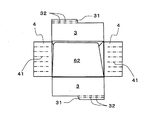
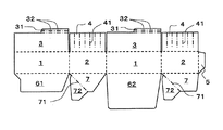
図1は、本発明の包装箱の一例の斜視図、図2は、本発明の包装箱の一例の上面を開いた状態の平面図、図3は、本発明の包装箱の一例の展開図、図4は、本発明の包装箱の一例の底面図である。
Hereinafter, modes for carrying out the present invention will be described.
1 is a perspective view of an example of the packaging box of the present invention, FIG. 2 is a plan view of an example of the packaging box of the present invention with the top surface opened, and FIG. 3 is an exploded view of an example of the packaging box of the present invention. FIG. 4 is a bottom view of an example of the packaging box of the present invention.
本例の包装箱は、板紙や段ボールを打ち抜き、折罫を設けたブランクを、折罫より折り曲げ、必要部分を接着して形成する。 The packaging box of this example is formed by punching a paperboard or cardboard, folding a blank provided with a crease, and folding the necessary part and bonding a necessary part.
本例の包装箱は、図1の斜視図のように、対向する一対の第一側部1、1と、組み立て時において第一側部1、1に直交する形で対向する一対の第二側部2、2と、一対の第一側部1、1のそれぞれの上端に折罫を介し設けられた外フラップ3、3と、一対の第二側部2、2のそれぞれの上端に折罫を介し設けられた内フラップ4、4とを有している。
As shown in the perspective view of FIG. 1, the packaging box of this example is a pair of
外フラップ3、3には、部分延長部31、31が対向するもう一方の外フラップ3、3の部分延長部以外に互いに重なるように設けられ、部分延長部31には、第一側部の上端の折罫と平行な第1予備折罫32、32が設けられている。尚、通常の折罫や、第1予備折罫32、32は、押罫で設けられるが、ミシン目や破線状の切れ目線で折罫を設けてもよい。
The
そして、図2の上面を開いたときの平面図のように、内フラップ4、4にも、第二側部2、2の上端の折罫と垂直な第2予備折罫41、41が設けられている。第2予備折罫41、41も押罫で設けられてもよいが、ミシン目や破線状の切れ目線で折罫を設けることが好ましい。これらのほうが柔軟に緩やかな曲線を作り、内容物による盛り上がりに対応できる。
As shown in the plan view when the upper surface of FIG. 2 is opened, the
本例の包装箱は、図3の展開図のようなブランクから、形成されている。すなわち、第一側部1と第二側部2が交互に横に並びその一端に糊代5が設けられている。一対の第一側部1、1のそれぞれの上端には、折罫を介して外フラップ3、3が設けられ、一対の第二側部2、2のそれぞれの上端には、折罫を介し内フラップ4、4が設けられている。
The packaging box of this example is formed from a blank as shown in the developed view of FIG. That is, the
外フラップ3、3には、部分延長部31、31が対向するもう一方の外フラップ3、3の部分延長部31、31以外に互いに重なるように設けられ、部分延長部31、31には、第一側部の上端の折罫と平行な第1予備折罫32、32が設けられている。また、内フラップ4、4にも、第二側部2、2の上端の折罫と垂直な第2予備折罫41、41が設けられている。
The
また、第一側部1、1のそれぞれの下端に、折罫を介し下端側内フラップ61、62が設けられている。そして、一方の下端側内フラップ62は、第二側部2、2の幅(長さ)と略同一になる程度に、他方の下端側内フラップ61より長く設けられ、包装箱の底部を補強するための床面を形成するようになっている。
In addition, lower end side
第二側部2、2のそれぞれの下端には、折罫を介し下端側外フラップ7、7が設けられている。そして、下端側外フラップには、第一側部1の下端の折罫と第二側部の下端の折罫との接続点を起点とする斜め折罫71、71を介して貼着板72、72が設けられている。斜め折罫71、71は、ミシン目や破線状の切れ目線で設けることが好ましい。これらの折罫で設けることによって、確実に底部の折畳みができるようになる。
Lower end-side
本例の包装箱を組み立てるには、まず、第一側部1、1と、第二側部2、2と、糊代5の間にある折罫を直角に折って、糊代5を重なり合う第一側部1の裏面に貼り付ける。こ
れにより四角筒状になる。
To assemble the packaging box of this example, first, fold the creases between the
一方の下端側内フラップ62を罫線で内側に直角に折り曲げ、包装箱の床面を形成するようにし、次に、他方の下端側内フラップ61も同様に内側に折り曲げる。続いて、下端側外フラップ7、7を罫線で内側に直角に折り曲げ、貼着板72、72を下端側内フラップ61、62の外面に糊などで接着させる。これにより、底部は、図4の底面図のように、形成される。
One of the lower end side
また、図2のように、一方の下端側内フラップ62が包装箱の底部を補強するための床面を形成するようになっている。そのため、床面がしっかりと強固に保たれ、隙間が生ずることがなく、ナットやボルトなどのような複数の重量物を収納しても、包装箱が壊れたり、床面から収納した内容物が落ちたりすることがない。
Moreover, as shown in FIG. 2, one lower end side
この底部を形成した包装箱を折畳むには、外フラップ3、3と内フラップ4、4を上にのばしたまま、底部を内側に押し込むと、斜め折罫71、71で谷折りされ、底部が折畳まれ、包装箱を平坦に折畳むことができる。
In order to fold the packaging box that forms the bottom, when the bottom is pushed inward with the
本例の包装箱に内容物を収納して梱包する方法について説明する。
図5は、本発明の包装箱の一例の天部を開いた状態の斜視図、図6は、本発明の包装箱の一例にPPバンド掛けした状態の斜視図である。
A method of storing the contents in the packaging box of this example and packing it will be described.
FIG. 5 is a perspective view showing a state in which the top of an example of the packaging box of the present invention is opened, and FIG. 6 is a perspective view showing a state in which the PP band is hung on an example of the packaging box of the present invention.
図5の斜視図のように、包装箱の外フラップ3、3と内フラップ4、4を外側に開いて、内容物を収納する。そして、内フラップ4、4と、外フラップ3、3を内側に倒す。このようにすると、図1のように、部分延長部31、31がそれぞれ対向する外フラップ3、3の上に重なる。このように重なっているので、内容物が若干多くなっても収納して蓋をすることができる。
As shown in the perspective view of FIG. 5, the
また、内フラップ4、4には、第2予備折罫41、41が設けられ、また、外フラップ3、3の部分延長部31、31にも第1予備折罫32、32が設けられているので、内容物に合わせて曲がって、内容物に密着し安定させることができる。そして、PPバンド8などでバンド掛けして、図6のように梱包することができる。
The
次に、包装箱を使用中に再封する方法について説明する。
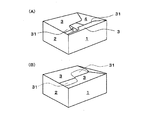
図7(A)、(B)は、本発明の包装箱の一例を再封する状態を示す斜視図である。
Next, a method for resealing the packaging box during use will be described.
FIGS. 7A and 7B are perspective views showing a state in which an example of the packaging box of the present invention is resealed.
内容物が使用されて少なくなって再封する場合、図7(A)のように、外フラップ3、3を包装箱のなかに押し込んで、離すと、図7(B)のように、部分延長部31、31がそれぞれ対向する外フラップ3、3の下になって重なった状態で蓋をすることができる。このようにして蓋をすると、外フラップ3、3が持ち上がってじゃまになることがない。
When the contents are used and reduced and resealed, the
以上のように、本例の包装箱は、その容量に対して内容物が若干多くなっても蓋をして収納することができる。また、使用前には、偏平に押しつぶすようにして平坦に折畳むことができ、簡単に底部を形成することができるので、使用前の搬送や保管に場所を取らず、コスト面でも有利である。また、一方の下端側内フラップ62を長くして、床面を形成しているので、しっかりとしてまた、隙間が生ずることがなく、安定して収納できる。
As described above, the packaging box of this example can be stored with a lid even if the contents are slightly larger than the capacity. Also, before use, it can be folded flat by flattening, and the bottom can be easily formed, saving space for transportation and storage before use, which is advantageous in terms of cost. . In addition, since the one lower end side
1、1・・・第一側部
2、2・・・第二側部
3、3・・・外フラップ
31、31・・・部分延長部
32、32・・・第1予備折罫
4、4・・・内フラップ
41、41・・・第2予備折罫
5・・・糊代
61、62・・・下端側内フラップ
7、7・・・下端側外フラップ
71、71・・・斜め折罫
72、72・・・貼着板
8・・・PPバンド
9・・・底面板
10、10、10、10・・・側面板
11・・・貼着片
12・・・ステイプル
13・・・身函
14・・・天面板
15、15、15、15・・・蓋側面板
16・・・被せ蓋
DESCRIPTION OF
Claims (4)
Priority Applications (1)
| Application Number | Priority Date | Filing Date | Title |
|---|---|---|---|
| JP2012216823A JP2014069843A (en) | 2012-09-28 | 2012-09-28 | Package box |
Applications Claiming Priority (1)
| Application Number | Priority Date | Filing Date | Title |
|---|---|---|---|
| JP2012216823A JP2014069843A (en) | 2012-09-28 | 2012-09-28 | Package box |
Publications (1)
| Publication Number | Publication Date |
|---|---|
| JP2014069843A true JP2014069843A (en) | 2014-04-21 |
Family
ID=50745425
Family Applications (1)
| Application Number | Title | Priority Date | Filing Date |
|---|---|---|---|
| JP2012216823A Pending JP2014069843A (en) | 2012-09-28 | 2012-09-28 | Package box |
Country Status (1)
| Country | Link |
|---|---|
| JP (1) | JP2014069843A (en) |
Cited By (2)
| Publication number | Priority date | Publication date | Assignee | Title |
|---|---|---|---|---|
| CN112849638A (en) * | 2021-04-12 | 2021-05-28 | 安徽省久恒慧通物流有限公司 | Packing box structure and folding method thereof |
| CN117813239A (en) * | 2021-06-17 | 2024-04-02 | 维实洛克包装系统有限公司 | End closures, article carriers and blanks therefor |
-
2012
- 2012-09-28 JP JP2012216823A patent/JP2014069843A/en active Pending
Cited By (2)
| Publication number | Priority date | Publication date | Assignee | Title |
|---|---|---|---|---|
| CN112849638A (en) * | 2021-04-12 | 2021-05-28 | 安徽省久恒慧通物流有限公司 | Packing box structure and folding method thereof |
| CN117813239A (en) * | 2021-06-17 | 2024-04-02 | 维实洛克包装系统有限公司 | End closures, article carriers and blanks therefor |
Similar Documents
| Publication | Publication Date | Title |
|---|---|---|
| JP2010526730A5 (en) | ||
| JP2014524393A (en) | Folding cardboard box | |
| TWM497637U (en) | Package box | |
| NO146689B (en) | SINGLE CHANNEL PULSE DOPPLER RADAR RECEIVER | |
| RU2737078C1 (en) | Waterproof and liquid-impermeable packing box from corrugated cardboard and method of manufacturing thereof | |
| KR102768301B1 (en) | Box with main flap overlap | |
| CN206297842U (en) | Packing case slab and packing case | |
| JP3196109U (en) | Pent roof type packaging box | |
| RU137745U1 (en) | BOX FOR PACKED PIECES (OPTIONS) | |
| JP6024951B2 (en) | Quadric carton | |
| RU117408U1 (en) | BOX FOR PACKED PIECES | |
| JP3204791U (en) | Packaging box | |
| JP5061003B2 (en) | Vanity box | |
| CN209467439U (en) | A modulus interspersed cushioning packing box | |
| JP3115322U (en) | Returnable box | |
| RU117407U1 (en) | BOX FOR PLACING PACKAGED PIECE PRODUCTS (OPTIONS) | |
| RU117409U1 (en) | BOX FOR PACKED PIECES | |
| JP3200021U (en) | Packing box with buffer function | |
| JP5103435B2 (en) | Packaging box | |
| RU122368U1 (en) | FOLDING CARTON BOX FOR PACKAGED PRODUCTS | |
| CN205738478U (en) | A kind of packing crates | |
| JP3115135U (en) | Packing storage box | |
| JP2004359279A (en) | Packaging box | |
| JP2016003025A (en) | Cardboard box and packing container | |
| JP5816541B2 (en) | Packaging container |