JP2014043671A - Drain basket - Google Patents
Drain basket Download PDFInfo
- Publication number
- JP2014043671A JP2014043671A JP2012184783A JP2012184783A JP2014043671A JP 2014043671 A JP2014043671 A JP 2014043671A JP 2012184783 A JP2012184783 A JP 2012184783A JP 2012184783 A JP2012184783 A JP 2012184783A JP 2014043671 A JP2014043671 A JP 2014043671A
- Authority
- JP
- Japan
- Prior art keywords
- drainage
- basket
- guide
- drain
- dust
- Prior art date
- Legal status (The legal status is an assumption and is not a legal conclusion. Google has not performed a legal analysis and makes no representation as to the accuracy of the status listed.)
- Pending
Links
- 239000000428 dust Substances 0.000 claims description 47
- 230000015572 biosynthetic process Effects 0.000 claims description 7
- 230000002093 peripheral effect Effects 0.000 claims description 6
- 239000002699 waste material Substances 0.000 claims description 4
- 239000010813 municipal solid waste Substances 0.000 abstract description 13
- 239000004071 soot Substances 0.000 description 5
- 238000004080 punching Methods 0.000 description 4
- 238000004140 cleaning Methods 0.000 description 3
- 238000007599 discharging Methods 0.000 description 3
- 230000000694 effects Effects 0.000 description 3
- 239000002184 metal Substances 0.000 description 3
- XLYOFNOQVPJJNP-UHFFFAOYSA-N water Substances O XLYOFNOQVPJJNP-UHFFFAOYSA-N 0.000 description 3
- 230000005540 biological transmission Effects 0.000 description 2
- 239000000463 material Substances 0.000 description 2
- 239000011148 porous material Substances 0.000 description 2
- 239000002351 wastewater Substances 0.000 description 2
- 230000007423 decrease Effects 0.000 description 1
- 239000008398 formation water Substances 0.000 description 1
- 235000021190 leftovers Nutrition 0.000 description 1
- 230000000630 rising effect Effects 0.000 description 1
- 229910001220 stainless steel Inorganic materials 0.000 description 1
- 239000010935 stainless steel Substances 0.000 description 1
- 235000013311 vegetables Nutrition 0.000 description 1
Images

Landscapes
- Sink And Installation For Waste Water (AREA)
Abstract
Description
本発明は、キッチンのシンク等の排水口に取付けられる排水カゴに関する。 The present invention relates to a drainage basket attached to a drainage port such as a sink of a kitchen.
従来のキッチンのシンク等の排水口に取付けられる排水カゴは、カゴ部全体がパンチングメタル等の多孔状素材や、網目状素材で構成されている。 A drainage basket attached to a drainage outlet of a conventional kitchen sink or the like has an entire cage portion made of a porous material such as punching metal or a mesh-like material.
例えば、複数の透過穴を備えゴミ捕集部として機能する受け部を有するストレーナ(排水目皿)において、受け部はパンチングメタルと呼ばれる、薄いステンレス板に複数の透過穴を穿設し、これを曲面形状椀状に加工した受け部を有する構成が知られている(特許文献1参照)。 For example, in a strainer (drainage pan) having a plurality of transmission holes and having a receiving part that functions as a dust collecting part, the receiving part is formed by punching a plurality of transmission holes in a thin stainless steel plate called a punching metal. A configuration having a receiving part processed into a curved bowl shape is known (see Patent Document 1).
また、排水が通過する網目状部及び排水が通過しない孔なし部とから成る捕集排水部を備え、排水中に含まれるゴミは、孔なし部に溜まることなく網目状部側に寄せられて溜まる構成の排水カゴが知られている(特許文献2参照)。 In addition, it has a collection drainage part consisting of a mesh part through which drainage passes and a holeless part through which drainage does not pass, and the dust contained in the drainage is attracted to the mesh part side without collecting in the holeless part. A drainage basket having a structure to accumulate is known (see Patent Document 2).
さらに、排水目皿を、断面形状が長い傾斜面部と短い傾斜面部とで略逆へ字状に形成することで、簡単にゴミを捨てることができ、ネット等を目皿のゴミ捕集面側に被せて使用する場合でも、ネットがゴミ捕集面に密着しないので、ゴミがネットを通って排水孔に絡む心配がなく、目皿をきれいな状態で使用することができるようにした構成が知られている(特許文献3参照)。 Furthermore, by forming the drainage pan in an inverted shape with an inclined surface portion with a long cross-sectional shape and a short inclined surface portion, it is possible to easily dispose of garbage, and the net etc. can be disposed on the dust collecting surface side of the eye plate. Even when used with a cover, the net does not adhere to the dust collection surface, so there is no concern about the dust passing through the net and getting caught in the drain hole, and it is known that the eye plate can be used in a clean state. (See Patent Document 3).
複数の排水用孔を形成した排水受部と排水受部の外周部の外周縁よりも内側に設けた立上部を備えたヘアキャッチャーにおいて、排水受部を立上部と反対側に向けて下降するように傾斜する傾斜面を有するようにした構成が知られている(特許文献4参照)。 In a hair catcher having a drain receiving part formed with a plurality of drain holes and an upright part provided on the inner side of the outer peripheral edge of the outer peripheral part of the drain receiving part, the drain receiving part is lowered toward the opposite side of the rising part. Such a configuration having an inclined surface that is inclined is known (see Patent Document 4).
排水口に取付けるゴミ受け本体を、その上方開口から底部に向かって内径を狭小しながら下向きに傾斜させた傾斜面部を形成し、底部の位置をゴミ受け本体の平面視において上方開口の中心部から偏心させて配置するようにした構成が知られている(特許文献5参照)。 The dust receiving body attached to the drainage port is formed with an inclined surface portion that is inclined downward while narrowing the inner diameter from the upper opening toward the bottom, and the position of the bottom is from the center of the upper opening in a plan view of the dust receiving body. A configuration is known that is arranged eccentrically (see Patent Document 5).
従来の排水カゴの構成では、キッチンで、発生した残菜や野菜等の切り屑等の厨芥が、排水孔に引っ掛かったり、排水カゴの取手を用いて捨てるときになかなか排水カゴから外れないという問題があった。 In the conventional drainage basket configuration, wastes such as leftovers and vegetables generated in the kitchen are caught in the drainage holes or are not easily removed from the drainage basket when discarded using the drainage basket handle. was there.
本発明は、上記従来の問題を解決することを目的とし、厨芥が、排水孔に引っ掛かったりしにくく、また、排水カゴから厨芥を外しやすいゴミ捨てが容易となる構造の排水カゴを実現することを課題とする。 An object of the present invention is to solve the above-described conventional problems, and to realize a drainage basket having a structure that makes it easy for the trash to be caught in the drainage hole and to easily remove the trash from the drainage basket. Is an issue.
本発明は上記課題を解決するために、全体として椀状に形成されるカゴ部と、カゴ部の周縁部に形成されるフランジ部と、フランジ部につながるように形成される取手部と、を備えた排水カゴであって、カゴ部は、カゴ部の全体の半分以上の面積を占める排水孔形成部と、排水孔形成部よりも面積の小さい排水孔非形成部とを有しており、排水孔非形成部は、取手部の下方から順次連続的に形成された排水ガイド部、ゴミ溜まり部及びゴミ捨てガイド部を有し、排水ガイド部は、排水孔形成部の領域において、取手部の下方からゴミ溜まり部に向かって略直線状に延びるように形成されていることを特徴とする排水カゴを提供する。 In order to solve the above-mentioned problems, the present invention includes a basket portion formed in a bowl shape as a whole, a flange portion formed at a peripheral portion of the cage portion, and a handle portion formed so as to be connected to the flange portion. The drainage basket provided, the basket part has a drainage hole forming part that occupies an area of more than half of the entire basket part, and a drainage hole non-forming part having a smaller area than the drainage hole forming part, The drain hole non-forming part has a drain guide part, a dust reservoir part and a dust disposal guide part successively formed from the lower part of the handle part, and the drain guide part has a handle part in the region of the drain hole forming part. The drainage basket is characterized by being formed so as to extend substantially linearly from the lower side toward the dust reservoir.
ゴミ捨てガイド部は、ゴミ溜まり部からフランジ部に向けて形成され、排水孔形成部よりも傾斜が急であることが好ましい。 The dust disposal guide part is preferably formed from the dust storage part toward the flange part, and has a steeper slope than the drain hole formation part.
排水ガイド部は、排水孔形成部の部位よりも下方に向けて凹んだ凹形状とされていることが好ましい。 It is preferable that the drainage guide portion has a concave shape that is recessed downward from the portion of the drainage hole forming portion.
排水孔非形成部は、排水ガイド部の両側における排水ガイド部の領域において、ゴミ溜まり部からフランジ部に向かって放射状に延びる複数の補助排水ガイド部を備えていることが好ましい。 The drain hole non-forming portion preferably includes a plurality of auxiliary drain guide portions extending radially from the dust pool portion toward the flange portion in the drain guide portion regions on both sides of the drain guide portion.
本発明は、次のような効果が生じる。
(1)排水孔が形成されていない排水ガイド部上を案内して厨芥を排出することができるので、従来例のように、排水孔形成部上に沿って厨芥を排出する場合に比較して、厨芥がカゴ部に引っ掛かることなく排水ガイド部上を滑らすようにして移動させることができるので、ゴミ捨てが容易となり、また、排水孔に詰まって残るようなことが減少し清掃が容易となる。
The present invention produces the following effects.
(1) Since the soot can be discharged by guiding it on the drain guide part where the drain hole is not formed, as compared with the case of discharging the soot along the drain hole forming part as in the conventional example. , It can be moved by sliding on the drainage guide part without being caught in the basket part, so that it is easy to throw away trash, and it is less likely to remain clogged in the drainage hole, which makes cleaning easier. .
本発明に係る排水カゴを実施するための形態を実施例に基づき図面を参照して、以下説明する。 EMBODIMENT OF THE INVENTION The form for implementing the waste water basket which concerns on this invention is demonstrated below with reference to drawings based on an Example.
(実施例1)
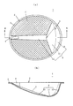
図1〜2は、本発明に係る排水カゴの実施例1を説明する図である。排水カゴ1は、全体として椀状に形成されるカゴ部2と、カゴ部2の周縁部に形成されるフランジ部3と、フランジ部3につながるように形成される取手部4と、を備えている。
Example 1
FIGS. 1-2 is a figure explaining Example 1 of the drainage basket which concerns on this invention. The
図1(a)、(b)に示すように、カゴ部2は、排水孔形成部7と排水孔非形成部8とを有している。排水孔形成部7は、平面視でカゴ部2の全体の半分以上の面積を占め、傾斜面として形成され、網目状素材を利用して網状に形成されている。排水孔形成部7は、図示はしないが、網状ではなく、例えばパンチングメタル等の多孔状素材を利用し、多数の排水孔が形成されている構成としてもよい。
As shown in FIGS. 1A and 1B, the
排水孔非形成部8は、カゴ部2の底に位置するゴミ溜まり部11と、排水ガイド部12と、ゴミ捨てガイド部13とを有しており、排水孔形成部7より面積が小さい。
The drain hole non-forming
排水ガイド部12は、排水孔形成部7の領域において、フランジ部3おける取手部4が位置する部分(取手部の下方)から、取手部4から遠い側(取手部4に対向する側)に向け、ゴミ溜まり部11まで、平面視で略直線状で下方に延びるように形成されている。
In the region of the drain
排水ガイド部12は、カゴ部2における排水孔形成部7の表面から下方に向けて凹んだ断面が凹形状に形成されている。要するに、排水ガイド部12は、排水孔形成部7の表面から凹んで延びる溝のように形成されている。
The
排水ガイド部12の取手部4側の上端は、フランジ部3に連続的に接続するように、その上端に近づく部分において序々に凹形状の深さが浅くなるように形成されている。また、排水ガイド部12の取手部4側と反対側の下端は、ゴミ溜まり部11に連続的に接続するように、その下端に近づく部分において序々に凹形状の深さが浅くなるように形成されている(図1(b)参照)。
The upper end of the
ゴミ溜まり部11は、排水ガイド部12の下端に連続的に接続され扇状に広がるとともに下方に向けて傾斜してから、徐々に上方に向けて緩やかに傾斜し、急傾斜のゴミ捨てガイド部13に連続的に接続されるように形成されている。
The
ゴミ捨てガイド部13は、取手部4から遠い側(取手部4に対向する側)に位置し、上記のとおり、ゴミ溜まり部11に連続的に接続するように形成されている。そして、ゴミ捨てガイド部13は、排水孔形成部7よりも傾斜が急で面積が小さく、排水孔は形成されていない。
The dust
なお、図1(a)において符号Sで示す曲線は、排水ガイド部12、ゴミ溜まり部11及びゴミ捨てガイド部13のおよその領域を把握する都合上、互いの境界あたりを示すために、便宜上記載したが、実際は、排水ガイド部12、ゴミ溜まり部11及びゴミ捨てガイド部13は、互いに連続的に接続されているので、この曲線Sのように明確に区分されるものではない。
In addition, the curve shown by the code | symbol S in Fig.1 (a) is shown for convenience, in order to show the approximate area | region of the
取手部4は、排水ガイド部12上において、カゴ部2の内面からカゴ部2の中心に張り出し、その上面は、フランジ部3の上面と面一となるように形成されている。このような取手部4を使用者が指で掴めば、排水カゴ1を持ち上げたり、傾けたりすることができる。
On the
(作用)
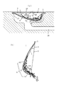
以上の構成から成る実施例1の排水カゴ1の作用を説明する。図2(a)は、排水カゴ1を、例えばキッチンのシンクの排水口17に装着し、厨芥19を捕集する状態を示す。排水蓋18を通して排水が矢印に示すように排水カゴ1内に流入すると、排水は、網状の排水孔形成部7の網目を通過し配水管20から排水される。
(Function)
The operation of the
排水中の厨芥19は、排水カゴ1の排水孔形成部7に引っ掛かって捕捉される。排水孔形成部7は傾斜面になっているので、捕捉された厨芥19は、排水カゴ1の下方に移動して、ゴミ溜まり部11に集まりやすい。
The
また、排水ガイド部12は、排孔非形成水部8の一部として形成されているので、厨芥19は排水で浮いて排水ガイド部12の上面に付着するようなことなく、排水とともに流下し(図2(a)の白抜き矢印F参照)、ゴミ溜まり部11に集まりやすい。
Moreover, since the
排水カゴ1内に捕集した厨芥19を捨てる場合には、使用者は取手部4を把持して排水カゴ1を排水口17から取り出す。そして、図2(b)に示すように、取手部4が上方で排水孔非形成部8が下方に位置する姿勢となるように、排水カゴ1全体を下方に向けて傾ける。
When throwing away the
すると、排水カゴ1のゴミ溜まり部11に捕集された厨芥19は、排水孔非形成部8の一部として形成されているゴミ捨てガイド部13上を滑るように案内されて移動し、排出される(図2(b)の白抜き矢印参照)。
Then, the
このように、排水孔非形成部8の一部として形成されているゴミ捨てガイド部13上を案内して厨芥19を排出することができるので、従来の排水カゴのような、排水孔の形成された面上に沿って厨芥を排出する場合に比較して、厨芥19がカゴ部2の内面に引っ掛かることなく、排水ガイド部12上を滑らすようにして移動させることができるので、ゴミ捨てが容易となり、また、厨芥19が排水孔形成部7の網目に詰まって残るようなことが減少し、清掃が容易となる。
In this way, since the
(実施例2)
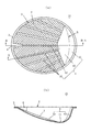
図3〜4は、本発明に係る排水カゴの実施例2を説明する図である。この実施例2は、実施例1とほぼ同じ構成であるので、相違する構成を中心に、以下説明する。なお、実施例2において、実施例1と同じ構成については同じ符号を付す。
(Example 2)
3-4 is a figure explaining Example 2 of the drainage basket which concerns on this invention. Since the second embodiment has almost the same configuration as that of the first embodiment, the following description will be focused on the different configuration. In the second embodiment, the same components as those in the first embodiment are denoted by the same reference numerals.
実施例2の排水カゴ31は、実施例1の排水カゴ1と同様に、全体として椀状に形成されるカゴ部2と、カゴ部2の周縁部に形成されるフランジ部3と、フランジ部3につながるように形成される取手部4と、を備えている。取手部4の上面は、フランジ部3の上面と面一につながるように形成されている。
The
実施例2の排水カゴ31においても、カゴ部2は、実施例1と同様に網状の排水孔形成部7と排水孔非形成部8とを有している。排水孔非形成部8は、排水ガイド部12、ゴミ溜まり部11、ゴミ捨てガイド部13及び後記する補助排水ガイド部32を、備えている。
Also in the
即ち、この実施例2の排水カゴ31は、実施例1の排水カゴ1と異なり、排水孔形成部7の領域において、排水ガイド部12の両側に、それぞれゴミ溜まり部11の下端縁から、該下端縁に対向する側のフランジ部3に向かって、平面視で放射状に略直線状で上方に傾斜して延びるように、複数の補助排水ガイド部32が形成されている(図3(a)参照)。
That is, the
この補助排水ガイド部32は、排水ガイド部12と異なり、凹形状には形成されておらず、カゴ部2の椀状の部分における排水孔形成部7を構成する部位と同一曲面内に形成されている。要するに、補助排水ガイド部32は、カゴ部2の椀状の傾斜した排水孔形成部7の領域において、排水孔形成部7と同一曲面内で、排水ガイド部12の両側に排水孔非形成部8の一部として帯状に形成されている。
Unlike the
なお、図3(a)に示す曲線Sは、実施例1の図1(a)の曲線Sと同様に、ゴミ溜まり部11とゴミ捨てガイド部13のおよその領域を把握する都合上、互いの境界あたりを示すために、便宜上記載したが、ゴミ溜まり部11とゴミ捨てガイド部13は互いに連続的に接続されているので、この曲線Sのように明確に区分されるものではない
Note that the curve S shown in FIG. 3A is similar to the curve S of FIG. 1A of the first embodiment for the sake of understanding the approximate areas of the
(作用)
以上の構成から成る実施例2の排水カゴ31の作用を説明する。実施例2の排水カゴ31の作用は、基本的には、実施例1の排水カゴ1の作用とほぼ同じである。しかし、実施例2の排水カゴ31は、排水孔形成部7の領域において、排水ガイド部12の両側に、放射状に略直線状に延びる複数の補助排水ガイド部32が設けられているので、実施例1の排水カゴ1の作用に加えて、次のような作用が生じる。
(Function)
The operation of the
即ち、矢印に示すように排水カゴ31内に流入した排水は、排水孔形成部7の網目から排水されるが、実施例1と同様に、排水の一部は、排水ガイド部12の上面を下方へ流下し、その際、排水ガイド部12の上面又はその近傍に付着した厨芥19を水で浮かすようにして下方に流す。
That is, as shown by the arrow, the wastewater that has flowed into the
加えて、実施例2の排水カゴ31では、図4(a)の白抜き矢印に示すように、排水カゴ31内に流入した排水の一部は、補助排水ガイド部32の上面に沿い下方へ流下する。その際、補助排水ガイド部32の上面又はその近傍に付着した厨芥19を水で浮かすようにして下方に流すので、厨芥19を排水カゴ31のゴミ溜まり部11上に集積して溜めやすくなる。
In addition, in the
また、排水カゴ31内に捕集した厨芥19を捨てる際に、実施例1の場合と同様に、取手部4を把持して、図4(b)に示すように、取手部4が上方で排水ガイド部12が下方に位置するような姿勢になるように、排水カゴ31全体を下方に向けて傾ける。
Further, when throwing away the
すると、実施例1の場合と同様に、排水カゴ31のゴミ溜まり部11に捕集された厨芥19は、排水孔非形成部8の一部として形成されているゴミ捨てガイド部13上を案内されて滑るように移動し、排出される(図4(b)の白抜き矢印参照)。
Then, as in the case of the first embodiment, the
なお、排水ガイド部12及び補助排水ガイド部32の下部辺りに溜まっている厨芥19は、排水ガイド部12及び補助排水ガイド部32上を案内されて滑るように下方に移動し、上記のように、ゴミ溜まり部11から排出される。
In addition, the
そのため、従来の排水カゴのように、排水孔の形成された面上に沿って厨芥を排出する場合に比較して、厨芥19が、カゴ部2の内面に引っ掛かることなく、排水ガイド部12、補助排水ガイド部32及びゴミ捨てガイド部13上を滑るようにして下方に移動し、ゴミ捨てが容易となり、また、排水孔形成部7の網目に詰まって残るようなことが減少し、清掃が容易となる。
Therefore, compared with the case of discharging the dredging along the surface where the drainage hole is formed as in the conventional drainage basket, the
以上、本発明に係る排水カゴを実施するための形態を実施例に基づいて説明したが、本発明はこのような実施例に限定されるものではなく、特許請求の範囲に記載された技術的事項の範囲内でいろいろな実施例があることは言うまでもない。 As mentioned above, although the form for implementing the drainage basket which concerns on this invention was demonstrated based on the Example, this invention is not limited to such an Example, The technical described in the claim It goes without saying that there are various embodiments within the scope of the matter.
本発明に係る排水カゴは上記のような構成であるから、キッチンのシンクの排水口に装着する排水カゴにかぎらず、必要に応じて、浴室、洗面シンク等の排水口に装着する排水カゴにも適用可能である。 Since the drainage basket according to the present invention is configured as described above, it is not limited to the drainage basket attached to the drainage outlet of the kitchen sink, and if necessary, the drainage basket attached to the drainage outlet of the bathroom, the sink or the like. Is also applicable.
1 排水カゴ
2 カゴ部
3 フランジ部
4 取手部
7 排水孔形成部
8 排水孔非形成部
11 ゴミ溜まり部
12 排水ガイド部
13 ゴミ捨てガイド部
17 排水口
18 排水蓋
19 厨芥
20 配水管
31 排水カゴ
32 補助排水ガイド部
DESCRIPTION OF
Claims (4)
Priority Applications (1)
| Application Number | Priority Date | Filing Date | Title |
|---|---|---|---|
| JP2012184783A JP2014043671A (en) | 2012-08-24 | 2012-08-24 | Drain basket |
Applications Claiming Priority (1)
| Application Number | Priority Date | Filing Date | Title |
|---|---|---|---|
| JP2012184783A JP2014043671A (en) | 2012-08-24 | 2012-08-24 | Drain basket |
Publications (1)
| Publication Number | Publication Date |
|---|---|
| JP2014043671A true JP2014043671A (en) | 2014-03-13 |
Family
ID=50395135
Family Applications (1)
| Application Number | Title | Priority Date | Filing Date |
|---|---|---|---|
| JP2012184783A Pending JP2014043671A (en) | 2012-08-24 | 2012-08-24 | Drain basket |
Country Status (1)
| Country | Link |
|---|---|
| JP (1) | JP2014043671A (en) |
Cited By (1)
| Publication number | Priority date | Publication date | Assignee | Title |
|---|---|---|---|---|
| JP2016160729A (en) * | 2015-03-05 | 2016-09-05 | Toto株式会社 | Net basket |
-
2012
- 2012-08-24 JP JP2012184783A patent/JP2014043671A/en active Pending
Cited By (1)
| Publication number | Priority date | Publication date | Assignee | Title |
|---|---|---|---|---|
| JP2016160729A (en) * | 2015-03-05 | 2016-09-05 | Toto株式会社 | Net basket |
Similar Documents
| Publication | Publication Date | Title |
|---|---|---|
| KR101194813B1 (en) | Refuse and oil collection bag | |
| EP1992746A2 (en) | Waste trap/plug assembly for sinks | |
| JP2011021412A (en) | Draining perforated plate | |
| JP5712478B2 (en) | Drainage basket | |
| KR20130040980A (en) | Drainage unit of sink ball for kitchen having improved disposal efficiency of food sludge | |
| JP2010255345A (en) | Drain perforated plate | |
| JP2014043669A (en) | Drain basket | |
| JP2009007784A (en) | Hair catcher | |
| JP2010275717A (en) | Drain grating | |
| JP2014190015A (en) | Hair catcher | |
| JP4894666B2 (en) | Hair catcher | |
| JP2016033312A (en) | Kitchen sink | |
| JP2001355264A (en) | Drain catch basin | |
| JP2010121424A (en) | Hair catcher | |
| JP2011153504A (en) | Hair catcher | |
| JP5573000B2 (en) | Draining eye plate | |
| JP2019019509A (en) | Hair catcher | |
| JP2007205164A (en) | Drainage port of bathroom | |
| CN112656199A (en) | Intelligent cooking machine with water receiving device | |
| JP2010126986A (en) | Strainer, and drain part structure having the same | |
| JP2009051646A (en) | Garbage receiving device | |
| JP4635268B2 (en) | Eye plate | |
| JP3214802U (en) | Grease interceptor catcher | |
| JP2016160729A (en) | Net basket | |
| JP2007120021A (en) | Drain trap |