JP2014017981A - Electronic control unit - Google Patents
Electronic control unit Download PDFInfo
- Publication number
- JP2014017981A JP2014017981A JP2012154088A JP2012154088A JP2014017981A JP 2014017981 A JP2014017981 A JP 2014017981A JP 2012154088 A JP2012154088 A JP 2012154088A JP 2012154088 A JP2012154088 A JP 2012154088A JP 2014017981 A JP2014017981 A JP 2014017981A
- Authority
- JP
- Japan
- Prior art keywords
- engine
- signal
- control device
- motor
- electronic control
- Prior art date
- Legal status (The legal status is an assumption and is not a legal conclusion. Google has not performed a legal analysis and makes no representation as to the accuracy of the status listed.)
- Pending
Links
Images


Classifications
-
- Y—GENERAL TAGGING OF NEW TECHNOLOGICAL DEVELOPMENTS; GENERAL TAGGING OF CROSS-SECTIONAL TECHNOLOGIES SPANNING OVER SEVERAL SECTIONS OF THE IPC; TECHNICAL SUBJECTS COVERED BY FORMER USPC CROSS-REFERENCE ART COLLECTIONS [XRACs] AND DIGESTS
- Y02—TECHNOLOGIES OR APPLICATIONS FOR MITIGATION OR ADAPTATION AGAINST CLIMATE CHANGE
- Y02T—CLIMATE CHANGE MITIGATION TECHNOLOGIES RELATED TO TRANSPORTATION
- Y02T10/00—Road transport of goods or passengers
- Y02T10/60—Other road transportation technologies with climate change mitigation effect
- Y02T10/72—Electric energy management in electromobility
Landscapes
- Electric Propulsion And Braking For Vehicles (AREA)
Abstract
【課題】既存のエンジン搭載車両に搭載されている電子制御装置のソフトウェアを改変することなく、且つ既存の車両統合制御システムに悪影響を及ぼすことなく、電気自動車への改造を実現可能な電子制御装置を提供する。
【解決手段】電子制御装置は、モータの回転センサから入力されるモータ回転信号をエンジン回転信号に変換してエンジン制御装置に出力する信号変換手段と、前記エンジン制御装置から入力されるエンジン制御信号の一部或いは全部に基づいて、エンジンの動作を模擬すると共に前記エンジンの状態を疑似的に表すエンジン状態信号を前記エンジン制御装置に出力するエンジン模擬手段とを備える。
【選択図】図1An electronic control device that can be modified into an electric vehicle without modifying software of the electronic control device mounted on an existing engine-equipped vehicle and without adversely affecting an existing vehicle integrated control system. I will provide a.
An electronic control device converts a motor rotation signal input from a motor rotation sensor into an engine rotation signal and outputs the engine rotation signal to the engine control device, and an engine control signal input from the engine control device. Engine simulation means for simulating the operation of the engine based on a part or all of the engine and outputting an engine state signal representing the state of the engine in a pseudo manner to the engine control device.
[Selection] Figure 1
Description
本発明は、電子制御装置に関する。 The present invention relates to an electronic control device.
一般的に、自動車はガソリンや軽油等の化石燃料によりエンジンを駆動して走行するが、排気ガスによる大気汚染等の問題から、近年では自動車の電動化に関する研究開発が盛んに行われている。研究開発用途で電気自動車を早期に試作する手法として、下記特許文献1及び2に記載されているように、既存のエンジン搭載車両をベースに電気自動車に改造する手法が挙げられる。この手法により、既存のエンジン搭載車両のエンジンを電動モータに置き換えて製作された電気自動車は、コンバージョンEVと呼ばれている。
In general, automobiles run by driving an engine with fossil fuels such as gasoline and light oil. Recently, research and development related to electrification of automobiles has been actively conducted due to problems such as air pollution caused by exhaust gas. As a technique for early trial production of an electric vehicle for research and development, there is a technique of remodeling an electric vehicle based on an existing engine-equipped vehicle, as described in
ところで、既存のエンジン搭載車両は、エンジンを構成する機械部品の他、エンジン制御装置を含む多数の電子制御装置がCAN等の車載ネットワークで接続された車両統合制御システムを備えているため、コンバージョンEVを製作するにあたって、単純にエンジン部品とエンジン制御装置を取り外した場合に、故障診断機能等のサービス機能が失われたり、他の電子制御装置の動作に悪影響を及ぼす可能性がある。 By the way, since an existing engine-equipped vehicle includes a vehicle integrated control system in which a number of electronic control devices including an engine control device are connected by an in-vehicle network such as CAN in addition to mechanical parts constituting the engine, a conversion EV If the engine parts and the engine control device are simply removed, the service functions such as the failure diagnosis function may be lost or the operation of other electronic control devices may be adversely affected.
この問題の対策として、エンジン部品とエンジン制御装置の取り外しに対応して、他の電子制御装置のソフトウェアを改変することも考えられるが、各電子制御装置のソフトウェアについては、一般的にブラックボックス化されているため、内部のソフトウェアを熟知している者でなければ、ソフトウェアの改変を行うことは容易ではない。 As a countermeasure against this problem, it is conceivable to modify the software of other electronic control devices in response to the removal of the engine parts and the engine control device, but the software of each electronic control device is generally made into a black box. Therefore, it is not easy to modify the software unless it is a person familiar with the internal software.
本発明は、上述した事情に鑑みてなされたものであり、既存のエンジン搭載車両に搭載されている電子制御装置のソフトウェアを改変することなく、且つ既存の車両統合制御システムに悪影響を及ぼすことなく、電気自動車への改造を実現可能な電子制御装置を提供することを目的とする。 The present invention has been made in view of the above-described circumstances, and does not alter the software of an electronic control device mounted on an existing engine-equipped vehicle and does not adversely affect an existing vehicle integrated control system. An object of the present invention is to provide an electronic control device that can be modified into an electric vehicle.
上記課題を解決するために、本発明では、電子制御装置に係る第1の解決手段として、モータの回転センサから入力されるモータ回転信号をエンジン回転信号に変換してエンジン制御装置に出力する信号変換手段と、前記エンジン制御装置から入力されるエンジン制御信号の一部或いは全部に基づいて、エンジンの動作を模擬すると共に前記エンジンの状態を疑似的に表すエンジン状態信号を前記エンジン制御装置に出力するエンジン模擬手段とを備える、という手段を採用する。 In order to solve the above-described problems, in the present invention, as a first solving means related to the electronic control device, a signal that converts a motor rotation signal input from a rotation sensor of the motor into an engine rotation signal and outputs the engine rotation signal to the engine control device. Based on the conversion means and part or all of the engine control signal inputted from the engine control device, the engine operation signal is simulated and an engine state signal representing the engine state is output to the engine control device. The engine simulating means is provided.
また、本発明では、電子制御装置に係る第2の解決手段として、上記第1の解決手段において、前記エンジン制御装置から入力される前記エンジン制御信号の一部と、前記信号変換手段から入力されるエンジン回転数と、外部入力されるスタータスイッチのオンオフ状態を示すスタータ信号とに基づいて、前記モータの作動を許可すべきか否かを判定するモータ作動判定手段をさらに備える、という手段を採用する。 According to the present invention, as a second solving means related to the electronic control device, in the first solving means, a part of the engine control signal inputted from the engine control device and the signal converting means are inputted. And a motor operation determining means for determining whether or not to permit the operation of the motor based on the engine speed and the starter signal indicating the on / off state of the starter switch input from the outside. .
また、本発明では、電子制御装置に係る第3の解決手段として、上記第2の解決手段において、前記モータ作動判定手段は、前記エンジン回転数がエンジン始動回転数より低いと判定され、且つ前記スタータ信号から前記スタータスイッチがオン状態であると判定されるという第1条件、または、前記エンジン制御信号の内の燃料噴射信号及び点火信号からエンジン動作要求があったと判定されるという第2条件のいずれか一方の条件が成立した場合に、前記モータの作動を許可する、という手段を採用する。 In the present invention, as a third solving means relating to the electronic control device, in the second solving means, the motor operation determining means determines that the engine speed is lower than the engine starting speed, and A first condition in which it is determined from the starter signal that the starter switch is in an on state, or a second condition in which it is determined that there has been an engine operation request from the fuel injection signal and the ignition signal in the engine control signal. A means of permitting the operation of the motor when any one of the conditions is satisfied is adopted.
また、本発明では、電子制御装置に係る第4の解決手段として、上記第1〜第3のいずれか一つの解決手段において、外部入力されるアクセルペダルの踏込み量を表すアクセルペダル信号或いはスロットル開度を表すスロットル開度信号に基づいて、前記モータの回転速度の設定に必要なアクセル量を算出するアクセル量算出手段をさらに備える、という手段を採用する。 Further, in the present invention, as a fourth solving means related to the electronic control unit, in any one of the first to third solving means, an accelerator pedal signal indicating a depression amount of an accelerator pedal input externally or a throttle opening is provided. A means is further provided that further comprises an accelerator amount calculating means for calculating an accelerator amount necessary for setting the rotational speed of the motor based on a throttle opening signal representing the degree.
また、本発明では、電子制御装置に係る第5の解決手段として、上記第1〜第4のいずれか一つの解決手段において、前記信号変換手段は、予めテーブルデータとして記憶されている前記エンジン回転信号の信号波形に基づいて、前記モータ回転信号から前記エンジン回転信号を生成する、という手段を採用する。 According to the present invention, as a fifth solving means related to the electronic control device, in any one of the first to fourth solving means, the signal converting means stores the engine rotation stored in advance as table data. Based on the signal waveform of the signal, means for generating the engine rotation signal from the motor rotation signal is adopted.
本発明によれば、既存のエンジン搭載車両からエンジンを取り外してモータに置き換え、エンジン制御装置を残したとしても、あたかもエンジンが存在しているかのようにエンジン制御装置を動作させることができるので、既存のエンジン搭載車両に搭載されている電子制御装置(エンジン制御装置を含む)のソフトウェアを改変することなく、且つ既存の車両統合制御システムに悪影響を及ぼすことなく、電気自動車への改造を実現できる。 According to the present invention, even if the engine is removed from an existing engine-equipped vehicle and replaced with a motor, and the engine control device is left, the engine control device can be operated as if the engine exists. A modification to an electric vehicle can be realized without modifying software of an electronic control device (including an engine control device) installed in an existing engine-equipped vehicle and without adversely affecting an existing vehicle integrated control system. .
以下、図面を参照しながら、本発明の一実施形態について説明する。
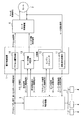
図1は、本実施形態に係る電子制御装置1の機能ブロック図である。この電子制御装置1は、既存のエンジン搭載車両からエンジンを取り外して動力源をモータ2に置き換えた車両(つまりコンバージョンEV)に搭載されている。このコンバージョンEVでは、エンジンを取り外しても既存のエンジン制御装置3は残しており、エンジン制御装置3を含む多数の車両制御用の電子制御装置4がCAN等の車載ネットワーク5で接続された車両統合制御システムも既存のまま残してある。
Hereinafter, an embodiment of the present invention will be described with reference to the drawings.
FIG. 1 is a functional block diagram of an
既存のエンジン制御装置3は、アクセルペダルの踏込み量を表すアクセルペダル信号(或いは機械式スロットルの場合にはスロットル開度を表すスロットル開度信号でも良い)と、エンジンの状態を表すエンジン状態信号(実際には、エンジンの所定位置に設置された各種センサの出力信号)とを入力し、これらの入力信号に基づいて生成したエンジン制御信号(実際にはエンジンに設けられた各種アクチュエータを制御するための信号)を出力するものである。
The existing
ここで、エンジンの状態を表すエンジン状態信号とは、例えば空燃比、吸気量、油温、冷却水温及び排気温などを表すセンサ信号や、クランク角度を表すクランク角信号及び上死点のタイミングを表すTDC信号等のエンジン回転信号などである。また、エンジン制御信号とは、例えば吸気バルブや電動スロットル、インジェクタ、点火プラグ等を制御するための信号などである。以下では、エンジン制御信号の内、特に、インジェクタを制御するための信号を燃料噴射信号、点火プラグを制御するための信号を点火信号と呼び、他の信号をアクチュエータ信号と呼ぶ。 Here, the engine state signal indicating the state of the engine includes, for example, a sensor signal indicating an air-fuel ratio, an intake air amount, an oil temperature, a coolant temperature, an exhaust gas temperature, a crank angle signal indicating a crank angle, and top dead center timing. An engine rotation signal such as a TDC signal to be represented. The engine control signal is, for example, a signal for controlling an intake valve, an electric throttle, an injector, a spark plug, and the like. Hereinafter, among the engine control signals, in particular, a signal for controlling the injector is called a fuel injection signal, a signal for controlling the spark plug is called an ignition signal, and the other signals are called actuator signals.
つまり、エンジンを取り外した後、エンジン制御装置3をあたかもエンジンが存在しているかのように動作させるには、上述したエンジン状態信号を疑似的に生成してエンジン制御装置3に入力する必要がある。本実施形態に係る電子制御装置1は、モータ2に設けられたエンコーダ等の回転センサ(図示省略)から入力されるモータ回転信号(モータ2の回転角を表す信号)をエンジン回転信号に変換してエンジン制御装置3に出力する機能と、エンジン制御装置3から入力されるアクチュエータ信号に基づいて、取り外したエンジンの動作を模擬すると共にエンジンの状態を疑似的に表すセンサ信号を生成してエンジン制御装置3に出力する機能を有している。
That is, after the engine is removed, in order to operate the
また、本実施形態のコンバージョンEVには、モータ2を制御するモータ制御装置6が新たに搭載されている。このモータ制御装置6は、電子制御装置1から出力されるアクセル量信号(モータ2の回転速度の設定に必要なアクセル量を表す信号)とモータ作動判定信号(モータ2の作動を許可すべきか否かの判定結果を表す信号)とを入力し、モータ作動判定信号がモータ2の作動許可を示している場合に、アクセル量信号が示すアクセル量に応じた回転速度でモータ2を回転させるためのモータ制御信号を生成してモータ2に出力する。
In addition, the conversion EV of the present embodiment is newly equipped with a
なお、このモータ制御装置6は、モータ2に設けられた回転センサから入力されるモータ回転信号に基づいて、モータ2の回転速度を算出し、この算出した回転速度がアクセル量に応じた回転速度(言い換えれば、目標回転速度)と一致するようにフィードバック制御を行う。
The
以下、本実施形態に係る電子制御装置1の機能について詳細に説明する。
電子制御装置1は、図1に示すように、回転信号変換部11(信号変換手段)と、エンジンシミュレータ12(エンジン模擬手段)と、モータ作動判定部13(モータ作動判定手段)と、アクセル量算出部14(アクセル量算出手段)とを備えている。
Hereinafter, functions of the
As shown in FIG. 1, the
回転信号変換部11は、モータ2の回転センサから入力されるモータ回転信号をエンジン回転信号(例えばクランク角信号及びTDC信号)に変換してエンジン制御装置3に出力する。具体的には、この回転信号変換部11は、図2に示すフローチャートに従ってエンジン回転信号(クランク角信号及びTDC信号)を生成する。なお、以下の説明においては、モータ2の1回転当たり360個のパルスが発生するモータ回転信号(図3(a)参照)を想定する。
The
図2に示すように、回転信号変換部11は、まず、モータ回転信号の立上がりを検出すると、立上がりの回数をカウントすることでパルス数をカウントし(ステップS1)、1パルス当たりの角度(ここでは、1パルス当たり1deg)にパルス数を乗算することで、モータ2の回転角度(以下、モータ角度と称す)を算出する(ステップS2)。回転信号変換部11は、上記ステップS2で算出したモータ角度が、後述のテーブル最終値(720deg)に相当する場合、モータ角度を0degにリセットすると共に、パルス数も0にリセットする(ステップS3)。
As shown in FIG. 2, when the rotation
そして、回転信号変換部11は、図3(b)に示すように、予めテーブルデータとして記憶しているクランク角信号の信号波形を参照して、モータ角度に対応するクランク角信号の電圧値を読み出し(ステップS4)、その読み出した電圧値を有する電圧信号をクランク角信号としてエンジン制御装置3に出力する(ステップS5)。
Then, as shown in FIG. 3B, the rotation
さらに、回転信号変換部11は、図3(c)に示すように、予めテーブルデータとして記憶しているTDC信号の信号波形を参照して、モータ角度に対応するTDC信号の電圧値を読み出し(ステップS6)、その読み出した電圧値を有する電圧信号をTDC信号としてエンジン制御装置3に出力する(ステップS7)。
Further, as shown in FIG. 3C, the rotation
回転信号変換部11は、モータ回転信号の立上がりを検出する度に、上記ステップS1からステップS7までの一連の処理を実行することにより、モータ2の回転センサから入力されるモータ回転信号をエンジン回転信号(クランク角信号及びTDC信号)に変換してエンジン制御装置3に出力する。また、この回転信号変換部11は、エンジン回転信号からエンジン回転数を算出し、その算出結果をモータ作動判定部13に出力する。
The
エンジンシミュレータ12は、エンジン制御装置3から入力されるエンジン制御信号の一部(例えば吸気バルブや電動スロットル等を制御するためのアクチュエータ信号)に基づいて、取り外したエンジンの動作を模擬すると共に、エンジンの状態を疑似的に表すエンジン状態信号(例えば空燃比、吸気量、油温、冷却水温及び排気温などを表すセンサ信号)を生成してエンジン制御装置3に出力する。
The
このようなエンジンシミュレータ12は、HILS(Hardware In the Loop Simulator)等の汎用的なプラントモデルシミュレータを利用して実現することができる。なお、このエンジンシミュレータ12は、物理式よりもさらに簡易化したモデルや、実負荷、実センサを用いるようなシミュレータで実現しても良い。また、エンジン制御装置3から入力されるエンジン制御信号の一部だけでなく、燃料噴射信号や点火信号を含む全部を使用してエンジン動作を模擬するエンジンシミュレータ12としても良い。
Such an
モータ作動判定部13は、エンジン制御装置3から入力されるエンジン制御信号の一部(例えば燃料噴射信号及び点火信号)と、回転信号変換部11から入力されるエンジン回転数と、外部入力されるスタータスイッチのオンオフ状態を示すスタータ信号とに基づいて、モータ2の作動を許可すべきか否かを判定し、その判定結果を示すモータ作動判定信号をモータ制御装置6に出力する。
The motor
具体的には、このモータ作動判定部13は、エンジン回転数がエンジン始動回転数より低いと判定され、且つスタータ信号からスタータスイッチがオン状態であると判定されるという第1条件、または、エンジン制御信号の内の燃料噴射信号及び点火信号からエンジン動作要求があったと判定されるという第2条件のいずれか一方の条件が成立した場合に、モータ2の作動を許可する。
Specifically, the motor
このように、エンジン回転数がエンジン始動回転数より低く、且つスタータスイッチがオン状態の場合は、エンジンシミュレータ12によりエンジン始動動作を模擬するために、モータ2の作動を許可している。また、エンジン制御装置3によってエンジン動作要求があった場合にモータ2を作動させ、エンジン停止要求があった場合にモータ2を停止させるように、エンジン制御信号の内の燃料噴射信号及び点火信号を監視している。
As described above, when the engine speed is lower than the engine start speed and the starter switch is in the ON state, the operation of the
なお、一般的に、燃料噴射信号及び点火信号は、オンレベルとオフレベルを有する矩形パルス状の信号であるので、両信号のオンレベルの状態を一定時間保持しておき、1つ以上の気筒の点火信号がオン、且つ1つ以上の気筒の燃料噴射信号がオンの場合にエンジン動作要求があったと判定すれば良い。 In general, since the fuel injection signal and the ignition signal are rectangular pulse signals having an on level and an off level, the on-level state of both signals is held for a certain period of time, and one or more cylinders It may be determined that there has been a request for engine operation when the ignition signal is on and the fuel injection signal for one or more cylinders is on.
アクセル量算出部14は、外部入力されるアクセルペダルの踏込み量を表すアクセルペダル信号(或いはスロットル開度を表すスロットル開度信号でも良い)に基づいて、モータ2の回転速度の設定に必要なアクセル量を算出し、その算出結果を示すアクセル量信号をモータ制御装置6に出力する。
The accelerator
具体的には、このアクセル量算出部14は、アクセルペダルの踏込み量とモータ2の回転速度の設定に必要なアクセル量との対応関係を表すテーブルデータを参照して、アクセルペダル信号が示すアクセルペダルの踏込み量に対応するアクセル量を取得する。このテーブルデータの設定によって、アクセルペダルの踏込み量が0の場合でも、一定のアクセル量を出力することで、モータ2によるクリープ状態を生み出すことができる。なお、エンジン制御装置3側でアイドル速度制御の異常を検出する場合には、エンジンシミュレータ12で算出した吸入空気量を使用してアクセル量をより正確に算出しても良い。
Specifically, the accelerator
以上のような機能を有する電子制御装置1を用いることにより、既存のエンジン搭載車両からエンジンを取り外してモータ2に置き換え、エンジン制御装置3を残したとしても、あたかもエンジンが存在しているかのようにエンジン制御装置3を動作させることができるので、既存のエンジン搭載車両に搭載されているエンジン制御装置3を含む電子制御装置4のソフトウェアを改変することなく、且つ既存の車両統合制御システムに悪影響を及ぼすことなく、電気自動車への改造を実現できる。
By using the
なお、本発明は上記実施形態に限定されず、以下のような変形例が挙げられる。
(1)上記実施形態では、電子制御装置1がモータ作動判定部13とアクセル量算出部14を備えている場合を例示したが、これらモータ作動判定部13とアクセル量算出部14は、必ずしも電子制御装置1に設ける必要はなく、例えばモータ制御装置6に設けても良い機能である。電子制御装置1には、少なくとも回転信号変換部11とエンジンシミュレータ12が設けられていれば、エンジンを取り外した後に、あたかもエンジンが存在しているかのようにエンジン制御装置3を動作させるという目的を達成することができる。
In addition, this invention is not limited to the said embodiment, The following modifications are mentioned.
(1) In the above embodiment, the case where the
(2)上記実施形態では、電子制御装置1とモータ制御装置6が別の装置として車両に搭載されている場合を例示したが、モータ制御装置6の機能を電子制御装置1に実装して、エンジンを取り外した後に、あたかもエンジンが存在しているかのようにエンジン制御装置3を動作させる機能(シミュレータとしての機能)と、モータ2を制御する機能の両方を電子制御装置1に持たせても良い。
(2) In the above embodiment, the case where the
1…電子制御装置、2…モータ、3…エンジン制御装置、6…モータ制御装置、11…回転信号変換部(信号変換手段)、12…エンジンシミュレータ(エンジン模擬手段)、13…モータ作動判定部(モータ作動判定手段)、14…アクセル量算出部(アクセル量算出手段)
DESCRIPTION OF
Claims (5)
前記エンジン制御装置から入力されるエンジン制御信号の一部或いは全部に基づいて、エンジンの動作を模擬すると共に前記エンジンの状態を疑似的に表すエンジン状態信号を前記エンジン制御装置に出力するエンジン模擬手段と、
を備えることを特徴とする電子制御装置。 A signal conversion means for converting a motor rotation signal input from a rotation sensor of the motor into an engine rotation signal and outputting the engine rotation signal to the engine control device;
Engine simulation means for simulating engine operation and outputting an engine state signal representing the engine state to the engine control device based on part or all of the engine control signal input from the engine control device When,
An electronic control device comprising:
Priority Applications (1)
| Application Number | Priority Date | Filing Date | Title |
|---|---|---|---|
| JP2012154088A JP2014017981A (en) | 2012-07-09 | 2012-07-09 | Electronic control unit |
Applications Claiming Priority (1)
| Application Number | Priority Date | Filing Date | Title |
|---|---|---|---|
| JP2012154088A JP2014017981A (en) | 2012-07-09 | 2012-07-09 | Electronic control unit |
Publications (1)
| Publication Number | Publication Date |
|---|---|
| JP2014017981A true JP2014017981A (en) | 2014-01-30 |
Family
ID=50112182
Family Applications (1)
| Application Number | Title | Priority Date | Filing Date |
|---|---|---|---|
| JP2012154088A Pending JP2014017981A (en) | 2012-07-09 | 2012-07-09 | Electronic control unit |
Country Status (1)
| Country | Link |
|---|---|
| JP (1) | JP2014017981A (en) |
Cited By (2)
| Publication number | Priority date | Publication date | Assignee | Title |
|---|---|---|---|---|
| JP2022023222A (en) * | 2017-01-25 | 2022-02-07 | エスイーエー オートモーティブ ピーティーワイ リミテッド | Management system for commercial electric vehicle |
| WO2024143095A1 (en) * | 2022-12-26 | 2024-07-04 | Freet株式会社 | Conversion vehicle, conversion kit, vehicle control device, and electronic control device |
-
2012
- 2012-07-09 JP JP2012154088A patent/JP2014017981A/en active Pending
Cited By (2)
| Publication number | Priority date | Publication date | Assignee | Title |
|---|---|---|---|---|
| JP2022023222A (en) * | 2017-01-25 | 2022-02-07 | エスイーエー オートモーティブ ピーティーワイ リミテッド | Management system for commercial electric vehicle |
| WO2024143095A1 (en) * | 2022-12-26 | 2024-07-04 | Freet株式会社 | Conversion vehicle, conversion kit, vehicle control device, and electronic control device |
Similar Documents
| Publication | Publication Date | Title |
|---|---|---|
| Klein et al. | Engine in the loop: Closed loop test bench control with real-time simulation | |
| Taglialatela et al. | Determination of combustion parameters using engine crankshaft speed | |
| US9151238B2 (en) | Fault diagnosis method, fault diagnosis system, and fault diagnosis device for engine | |
| JP2019100300A (en) | Controller and control method of internal combustion engine | |
| KR20200094201A (en) | Test bench and test method | |
| CN104111650A (en) | Dual-fuel engine controller simulation test system | |
| Isermann et al. | Design of computer controlled combustion engines | |
| Saracino et al. | Cylinder pressure-based closed loop combustion control: A valid support to fulfill current and future requirements of diesel powertrain systems | |
| CN113176739A (en) | Vehicle control device, vehicle control method, and non-transitory computer readable medium storing vehicle control program | |
| Dorscheidt et al. | Hardware-in-the-loop based virtual emission calibration for a gasoline engine | |
| WO2005028839A1 (en) | Method and system for adaptation of transient engine performance | |
| EP2924272A1 (en) | Control device of internal combustion engine | |
| Malikopoulos et al. | Optimal engine calibration for individual driving styles | |
| JP2014017981A (en) | Electronic control unit | |
| WO2006059682A1 (en) | Transient engine performance adaptation method and system | |
| KR101205247B1 (en) | Fuel Consumption Measuring System For Commercial Vehicle on HILS System | |
| Wan et al. | Engine modelling architecture study for hybrid electric vehicle diagnosis application | |
| JP2009046988A (en) | Control device for internal combustion engine | |
| JP2012013637A (en) | Adaptation method and adaptation device for engine control parameter | |
| Winward et al. | Innovations in experimental techniques for the development of fuel path control in diesel engines | |
| Chen et al. | Development of engine model using modulization method for EMS verification through MIL and HIL | |
| CN115144668A (en) | Fault detection method, signal simulator and fault detection system | |
| CN103975153A (en) | Conrol device for internal combustion engine | |
| JP2009198305A (en) | Experiment method for engine control component | |
| JP2008008236A (en) | Simulation method and device of four-cycle multi-cylinder gas engine |