JP2014017167A - Fixing structure of fuse holder and fuse cover - Google Patents
Fixing structure of fuse holder and fuse cover Download PDFInfo
- Publication number
- JP2014017167A JP2014017167A JP2012154913A JP2012154913A JP2014017167A JP 2014017167 A JP2014017167 A JP 2014017167A JP 2012154913 A JP2012154913 A JP 2012154913A JP 2012154913 A JP2012154913 A JP 2012154913A JP 2014017167 A JP2014017167 A JP 2014017167A
- Authority
- JP
- Japan
- Prior art keywords
- fuse
- fuse cover
- cover
- holder
- return
- Prior art date
- Legal status (The legal status is an assumption and is not a legal conclusion. Google has not performed a legal analysis and makes no representation as to the accuracy of the status listed.)
- Granted
Links
Images



Classifications
-
- H—ELECTRICITY
- H01—ELECTRIC ELEMENTS
- H01R—ELECTRICALLY-CONDUCTIVE CONNECTIONS; STRUCTURAL ASSOCIATIONS OF A PLURALITY OF MUTUALLY-INSULATED ELECTRICAL CONNECTING ELEMENTS; COUPLING DEVICES; CURRENT COLLECTORS
- H01R13/00—Details of coupling devices of the kinds covered by groups H01R12/70 or H01R24/00 - H01R33/00
- H01R13/62—Means for facilitating engagement or disengagement of coupling parts or for holding them in engagement
- H01R13/627—Snap or like fastening
- H01R13/6271—Latching means integral with the housing
- H01R13/6272—Latching means integral with the housing comprising a single latching arm
-
- H—ELECTRICITY
- H01—ELECTRIC ELEMENTS
- H01H—ELECTRIC SWITCHES; RELAYS; SELECTORS; EMERGENCY PROTECTIVE DEVICES
- H01H85/00—Protective devices in which the current flows through a part of fusible material and this current is interrupted by displacement of the fusible material when this current becomes excessive
- H01H85/02—Details
- H01H85/20—Bases for supporting the fuse; Separate parts thereof
- H01H85/2045—Mounting means or insulating parts of the base, e.g. covers, casings
-
- H—ELECTRICITY
- H01—ELECTRIC ELEMENTS
- H01R—ELECTRICALLY-CONDUCTIVE CONNECTIONS; STRUCTURAL ASSOCIATIONS OF A PLURALITY OF MUTUALLY-INSULATED ELECTRICAL CONNECTING ELEMENTS; COUPLING DEVICES; CURRENT COLLECTORS
- H01R13/00—Details of coupling devices of the kinds covered by groups H01R12/70 or H01R24/00 - H01R33/00
- H01R13/44—Means for preventing access to live contacts
- H01R13/447—Shutter or cover plate
-
- H—ELECTRICITY
- H01—ELECTRIC ELEMENTS
- H01R—ELECTRICALLY-CONDUCTIVE CONNECTIONS; STRUCTURAL ASSOCIATIONS OF A PLURALITY OF MUTUALLY-INSULATED ELECTRICAL CONNECTING ELEMENTS; COUPLING DEVICES; CURRENT COLLECTORS
- H01R33/00—Coupling devices specially adapted for supporting apparatus and having one part acting as a holder providing support and electrical connection via a counterpart which is structurally associated with the apparatus, e.g. lamp holders; Separate parts thereof
- H01R33/945—Holders with built-in electrical component
- H01R33/95—Holders with built-in electrical component with fuse; with thermal switch
-
- H—ELECTRICITY
- H01—ELECTRIC ELEMENTS
- H01H—ELECTRIC SWITCHES; RELAYS; SELECTORS; EMERGENCY PROTECTIVE DEVICES
- H01H85/00—Protective devices in which the current flows through a part of fusible material and this current is interrupted by displacement of the fusible material when this current becomes excessive
- H01H85/54—Protective devices wherein the fuse is carried, held, or retained by an intermediate or auxiliary part removable from the base, or used as sectionalisers
- H01H85/547—Protective devices wherein the fuse is carried, held, or retained by an intermediate or auxiliary part removable from the base, or used as sectionalisers with sliding fuse carrier
Landscapes
- Fuses (AREA)
Abstract
【課題】ヒューズホルダとヒューズカバーを組み付けるための固定構造の省スペース化を図る。
【解決手段】バスバモジュールに接続されるヒューズを保持するヒューズホルダ2と、ヒューズを絶縁するヒューズカバー4とを組み付けるための固定構造1であって、ヒューズホルダは、ヒューズカバーとの組み付け方向に立設された突起部26を備え、ヒューズカバーは、突起部を係合させる係合部42を備えており、係合部は、組み付け方向に沿ってヒューズカバーを貫通させて形成された貫通孔であり、貫通孔は、組み付け方向に対してヒューズカバー側の開口をヒューズホルダ側へ凹ませて形成された段差部44を有し、突起部は、貫通孔に挿通されて段差部と係合される返し部28を有し、返し部は、段差部と係合された状態において、組み付け方向に対してヒューズカバー側の端部28tが貫通孔のヒューズカバー側の開口周縁48に位置付けられる構成とする。
【選択図】 図1To save space of a fixing structure for assembling a fuse holder and a fuse cover.
A fixing structure for assembling a fuse holder (2) for holding a fuse connected to a bus bar module and a fuse cover (4) for insulating the fuse, wherein the fuse holder stands in an assembling direction with the fuse cover. The fuse cover is provided with an engaging portion 42 for engaging the protruding portion, and the engaging portion is a through hole formed by penetrating the fuse cover along the assembly direction. The through hole has a stepped portion 44 formed by denting the opening on the fuse cover side toward the fuse holder side with respect to the assembly direction, and the protruding portion is inserted into the through hole and engaged with the stepped portion. When the return portion is engaged with the stepped portion, the end portion 28t on the fuse cover side with respect to the assembling direction is the opening circumference of the through hole on the fuse cover side. A configuration that is positioned 48.
[Selection] Figure 1
Description
本発明は、バスバモジュールに使用されるヒューズを保持するヒューズホルダとヒューズカバーとを組み付けるための固定構造に関する。 The present invention relates to a fixing structure for assembling a fuse holder and a fuse cover for holding a fuse used in a bus bar module.
従来から、電気部品の接続用回路の一つとして、バスバモジュールが広く用いられている。バスバモジュールは、導体平板を打ち抜き加工や折り曲げ加工等してなる複数のバスバを絶縁基板上に配索して構成されている。使用にあたっては、ヒューズが接続され、バスバモジュールに対して定格外の電流が流れることを防止し、安全が図られている。この場合、ヒューズは、所定の保持部材(以下、ヒューズホルダという。)に保持され、かかるヒューズホルダは、カバー部材(同、ヒューズカバーという。)が組み付けられて絶縁されている。その際、ヒューズホルダとヒューズカバーは相互に固定され、容易には外れないように組み付けられる。特許文献1には、このような固定構造の一例が開示されている。
Conventionally, a bus bar module has been widely used as one of circuits for connecting electrical components. The bus bar module is configured by arranging a plurality of bus bars formed by punching or bending a conductive flat plate on an insulating substrate. In use, a fuse is connected to prevent a non-rated current from flowing to the bus bar module, thereby ensuring safety. In this case, the fuse is held by a predetermined holding member (hereinafter referred to as a fuse holder), and the fuse holder is insulated by assembling a cover member (hereinafter referred to as a fuse cover). At that time, the fuse holder and the fuse cover are fixed to each other and assembled so as not to be easily removed.
特許文献1に開示された固定構造においては、係止突起と弾性係止アームを相互に係止させている。この場合、相互に組み付けられる2つのボックス構成部材の一方に係止突起、他方に弾性係止アームをそれぞれ設け、これらを固定させる際には弾性係止アームを固定方向(ボックス構成部材の組み付け方向)へ移動させる。これにより、弾性係止アームの先端に突設された先端係止部が係止突起に突き当たり、弾性係止アームが弾性撓み変形して係止突起を乗り越える。そして、先端係止部が係止突起を完全に乗り越える位置まで移動が進むと、弾性係止アームが撓み復帰変形して先端係止部が係止突起に係止される構造となっている。
In the fixing structure disclosed in
ただし、このような固定構造では、ロック保持力は弾性係止アームの弾性復帰力のみに依存し、固定位置の弾性係止アームに強いロック解除力が作用して弾性係止アームが弾性撓み変形した場合、先端係止部と係止突起との係止が解かれる。そこで、係止突起及び弾性係止アームに加えて、弾性係止アームの弾性撓み変形を抑制するためのリブ(アーム規制リブ)を設けた構造が開示されている。かかるアーム規制リブは、係止突起に係止される弾性係止アームの背面側に配置されており、弾性係止アームの固定方向への移動時には先端係止部と干渉することはない。その一方で、固定位置の弾性係止アームに対してロック解除力が作用した場合には、かかる弾性係止アームと干渉し、該弾性係止アームが大きく弾性撓み方向に変位できないように構成されている。このようにアーム規制リブを設けることで、より解除し難い固定構造の実現を図っている。 However, in such a fixing structure, the lock holding force depends only on the elastic return force of the elastic locking arm, and the elastic locking arm is elastically deformed by a strong unlocking force acting on the elastic locking arm at the fixed position. In this case, the locking between the tip locking portion and the locking projection is released. Thus, a structure is disclosed in which, in addition to the locking protrusion and the elastic locking arm, a rib (arm regulating rib) for suppressing the elastic bending deformation of the elastic locking arm is disclosed. The arm restricting rib is disposed on the back side of the elastic locking arm locked by the locking projection, and does not interfere with the tip locking portion when the elastic locking arm moves in the fixing direction. On the other hand, when an unlocking force is applied to the elastic locking arm at the fixed position, the elastic locking arm interferes with the elastic locking arm, so that the elastic locking arm cannot be displaced greatly in the elastic bending direction. ing. By providing the arm regulating rib in this manner, a fixing structure that is more difficult to release is realized.
しかしながら、かかる固定構造では、リブを設ける必要があるため、その配設スペースを他の部品との関係(例えば、配設位置等)を考慮しつつ確保しなければならない。また、リブを設ける分だけ、使用樹脂量等の増大を招くこととなる。したがって、ヒューズホルダとヒューズカバーの小型軽量化を図る上では課題が残る。 However, since it is necessary to provide ribs in such a fixing structure, the arrangement space must be secured in consideration of the relationship with other parts (for example, the arrangement position). In addition, the amount of resin used increases as much as the ribs are provided. Therefore, a problem remains in reducing the size and weight of the fuse holder and the fuse cover.
本発明はこれを踏まえてなされたものであり、その解決しようとする課題は、ヒューズホルダとヒューズカバーを組み付けるための固定構造の省スペース化を図ることにある。 The present invention has been made on the basis of this, and a problem to be solved is to save space of a fixing structure for assembling a fuse holder and a fuse cover.
上記課題を解決するため、本発明は、バスバモジュールに接続されるヒューズを保持するヒューズホルダと、ヒューズを絶縁するヒューズカバーとを組み付けるための固定構造であって、ヒューズホルダは、ヒューズカバーとの組み付け方向に立設された突起部を備え、ヒューズカバーは、突起部を係合させる係合部を備えており、係合部は、組み付け方向に沿ってヒューズカバーを貫通させて形成された貫通孔であり、貫通孔は、組み付け方向に対してヒューズカバー側の開口を前記ヒューズホルダ側へ凹ませて形成された段差部を有し、突起部は、貫通孔に挿通されて段差部と係合される返し部を有し、返し部は、段差部と係合された状態において、組み付け方向に対してヒューズカバー側の端部が貫通孔のヒューズカバー側の開口周縁に位置付けられることを特徴とする。 In order to solve the above-described problems, the present invention provides a fixing structure for assembling a fuse holder that holds a fuse connected to a bus bar module and a fuse cover that insulates the fuse. The fuse cover has an engaging portion that engages the protruding portion, and the engaging portion penetrates the fuse cover along the assembling direction. The through hole has a stepped portion formed by recessing the opening on the fuse cover side toward the fuse holder side with respect to the assembly direction, and the protruding portion is inserted into the through hole and engaged with the stepped portion. The end portion on the fuse cover side with respect to the assembling direction is an opening peripheral edge on the fuse cover side of the through hole in a state where the return portion is engaged with the stepped portion. Characterized in that it is positioned.
これによれば、ヒューズホルダの突起部(具体的には、返し部)をヒューズカバーの係合部(具体的には、段差部)と係合させることで、ヒューズホルダとヒューズカバーを相互に組み付けることができる。併せて、返し部の端部を係合部の開口周縁と干渉させることができるため、突起部と係合部との係合を解除させることなく、ヒューズホルダとヒューズカバーが相互に組み付けられた状態を維持することが可能となる。 According to this, by engaging the protrusion (specifically, the return portion) of the fuse holder with the engaging portion (specifically, the step portion) of the fuse cover, the fuse holder and the fuse cover are mutually connected. Can be assembled. In addition, since the end of the return portion can interfere with the opening periphery of the engaging portion, the fuse holder and the fuse cover are assembled to each other without releasing the engagement between the protruding portion and the engaging portion. It becomes possible to maintain the state.
この場合において、返し部は、組み付け方向に対する返しの長さを段差部の組み付け方向に対する段差高さと略同一に設定すればよい。これにより、返し部の全体を係合部と干渉可能な状態に位置付けることができる。 In this case, the return part should just set the return length with respect to the assembly direction substantially the same as the step height with respect to the assembly direction of the step part. Thereby, the whole return part can be positioned in the state which can interfere with an engaging part.
本発明によれば、ヒューズホルダとヒューズカバーを組み付けるための固定構造の省スペース化を図ることができる。 According to the present invention, it is possible to save the space of the fixing structure for assembling the fuse holder and the fuse cover.
以下、本発明のヒューズホルダとヒューズカバーとの固定構造(以下、単に固定構造という。)について、添付図面を参照して説明する。かかる固定構造は、バスバモジュールに接続されるヒューズを保持するヒューズホルダと、前記ヒューズを絶縁するヒューズカバーとを組み付けるためのものである。バスバモジュールは、自動車等の車両に搭載される電源装置と負荷(電動モータ等)との接続用の回路として構成される場合を一例として想定するが、その他の電気部品における接続用の回路として構成することも可能であり、これを特に排除するものではない。なお、バスバモジュールは、導体平板を打ち抜き加工や折り曲げ加工等してなる複数のバスバを絶縁基板上に配索して構成すればよく、その形状及び端子の種類や数は特に限定されない。 Hereinafter, a fixing structure (hereinafter simply referred to as a fixing structure) between a fuse holder and a fuse cover of the present invention will be described with reference to the accompanying drawings. Such a fixing structure is for assembling a fuse holder for holding a fuse connected to the bus bar module and a fuse cover for insulating the fuse. The bus bar module is assumed to be configured as a circuit for connecting a power supply device mounted on a vehicle such as an automobile and a load (such as an electric motor) as an example, but configured as a circuit for connection in other electrical components. It is also possible to do this, and this is not specifically excluded. The bus bar module may be configured by arranging a plurality of bus bars formed by punching or bending a conductive flat plate on an insulating substrate, and the shape and type and number of terminals are not particularly limited.
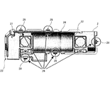
図1〜図4には、本発明の一実施形態に係る固定構造1の構成を示す。図1は、かかる固定構造1により相互に組み付けられたヒューズホルダ2とヒューズカバー4の全体構成を示す図、図2は、ヒューズホルダ2の構成を示す平面図、図3は、図1における円内部分の固定構造1を、相互に組み付けられたヒューズホルダ2とヒューズカバー4の側面方向から拡大して示す図、図4は、図3の矢印A3部分における縦断面を矢印方向から示す図である。なお、以下の説明においては、ヒューズホルダ2とヒューズカバー4の組み付け方向(一例として、図3及び図4における上下方向)に対してヒューズカバー4側(一例として、同各図における上側)を蓋側、ヒューズホルダ2側(同、下側)を底側という。
1 to 4 show a configuration of a
ヒューズホルダ2は、ヒューズを保持するための樹脂製の筺体であり、該ヒューズが収容される収容部22を有する底部21と、底部21の周縁から蓋側へ延出するように設けられた枠部23とを備えている。図2に示す構成においては、底部21の周縁から略垂直上向きに枠部23が全周に亘って立設されており、かかる枠部23内の収容部22にヒューズユニット24が収容された状態となっている。ヒューズユニット24は、ヒューズ、該ヒューズを収容部22に固定するための固定具(固定用金属片やねじ等)、及びバスバモジュールとの接続用の端子などを含んで構成されている。なお、収容部22及びヒューズユニット24は、かかるヒューズユニット24を収容部22に収容することが可能であれば、大きさや形状等の構成は任意に設定することが可能である。
The
これに対し、ヒューズカバー4は、ヒューズ(ヒューズユニット24)を絶縁するためにヒューズホルダ2に対して組み付けられる樹脂製のカバー部材(被覆体)として構成されており、ヒューズホルダ2の底部21を覆う蓋部41と、蓋部41の周縁から底側(一例として、略垂直下向き)へ延出するように全周に亘って設けられて枠部23の外側へ重なる壁部43とを備えている。この場合、ヒューズカバー4は、ヒューズユニット24が収容部22に収容されたヒューズホルダ2に対して垂直方向の上方から組み付けられ、組み付け後はヒューズホルダ2と一体をなして取り回すことが可能な構成となっている。これにより、ヒューズユニット24をバスバモジュールへ容易に接続させることを可能としている。また、ヒューズホルダ2とヒューズカバー4が組み付けられた状態においては、その内部にヒューズユニット24の全体を収容可能な空間を生じさせることができる。なお、本実施形態においては、ヒューズホルダ2とヒューズカバー4の組み付け方向を垂直方向としているが、かかる組み付け方向を水平方向とし、ヒューズカバー4をヒューズホルダ2に対して水平方向の一方側から組み付ける固定構造とすることも想定可能である。
On the other hand, the
本実施形態に係る固定構造1として、ヒューズホルダ2は、ヒューズカバー4との組み付け方向に立設された突起部(以下、ヒューズカバーロックという。)26を備えている。また、ヒューズカバー4は、ヒューズカバーロック26を係合させるための係合部42を備えている。この場合、ヒューズカバーロック26及び係合部42の少なくとも一方は、弾性を有する構成となっている。例えば、ヒューズカバーロック26を弾性材(一例として、樹脂材)で成形し、係合部42に対して弾性変形可能な構成とすればよい。その際、ヒューズホルダ2の全体、あるいは枠部23をヒューズカバーロック26とともに同一の弾性樹脂材で成形することも可能である。これにより、ヒューズカバーロック26が係合部42に対して弾性変形して該係合部42と係合され、ヒューズホルダ2とヒューズカバー4が相互に係止された状態で組み付けられる。ヒューズカバーロック26及び係合部42は、複数かつ同数がヒューズホルダ2及びヒューズカバー4に対してそれぞれ備えられていればよく、その数は特に限定されない。図1及び図2には、5つのヒューズカバーロック26及び係合部42を備えたヒューズホルダ2及びヒューズカバー4の構成を一例として示す。この場合、ヒューズカバーロック26は、ヒューズホルダ2の収容部22を取り囲むようにヒューズホルダ2の周縁部(具体的には、枠部23)へ分散して配されており、係合部42は、これらのヒューズカバーロック26に対応して位置付けられるようにヒューズカバー4の周縁部へ分散して配されている。これにより、ヒューズホルダ2及びヒューズカバー4をこれらの周縁の複数個所(一例として、5箇所)で相互に係止させ、安定して組み付けることができる。
As the fixing
係合部42は、組み付け方向に沿ってヒューズカバー4を貫通させて形成された貫通孔となっている(図3及び図4参照)。すなわち、係合部42は、組み付け方向に対し、蓋側と底側にそれぞれ開口を有する貫通孔として形成される。かかる貫通孔は、蓋側の開口を底側へ凹ませて形成された段差部44を有している。つまり、係合部42は、蓋部41と壁部43との連続部分を矩形に切り欠いた状態(蓋側の開口の一部を底側へ凹ませた状態)で、ヒューズカバー4を組み付け方向へ貫通した構成となっている。これにより、貫通孔の孔壁部45は、段差部44において外部へ露出された状態となっている。また、係合部42には、段差部44の段差面44sから底側へ突出してヒューズカバーロック26をガイドするための導入部46が設けられている。導入部46は、内側から外側(図4においては、左側から右側)へ徐々に傾斜する傾斜面46sを有し、底側に向かうに従って先細りとなるように構成されている。
The engaging
これに対し、ヒューズカバーロック26は、ヒューズホルダ2の底部21から枠部23に沿って板状に立設されている。この場合、ヒューズカバーロック26は、係合部42である貫通孔に挿通されて段差部44(より具体的には、その段差面44s)と係合される返し部28を有している。返し部28は、ヒューズカバーロック26の蓋側の端部近傍に外側(図4においては、右側)へ向けて突設されている。また、返し部28は、外側から内側(図4においては、右側から左側)へ徐々に傾斜する傾斜面28sを有し、蓋側に向かうに従って先細りとなるように構成されている。すなわち、返し部28は、導入部46とは組み付け方向に対して逆向きの先細り状をなした構成となっている。これにより、ヒューズカバーロック26を係合部42である貫通孔に挿通させる際、傾斜面28sを導入部46の傾斜面46sに当接させることで、返し部28を傾斜面46sに沿ってスムーズに移動させることができ、ヒューズカバーロック26(端的には、返し部28)を係合部42へ容易に導くことができる。その際、返し部28の傾斜面28sは、突出部46の傾斜面46sに沿って傾斜するように組み付け方向に対する傾斜角度を設定することが好ましい。なお、返し部28は、段差部44と係合可能となるように、ヒューズカバーロック26の組み付け方向の蓋側端部近傍から突設させればよい。例えば、返し部28は、外側への突出幅(図4に示す距離W)に亘って段差部44と係合可能、換言すれば、返し面28bの全体が段差面44sと係合可能となるように構成すればよい。なお、段差面44sの幅(図4における左右方向の距離)は、導入部46の基端部分の肉厚に相当する。
On the other hand, the
そして、返し部28は、ヒューズカバーロック26を段差部44と係合させた状態において、組み付け方向の蓋側端部28tが係合部42である貫通孔の蓋側の開口周縁48に位置付けられている。この場合、返し部28は、組み付け方向に対する返しの長さ(図4に示す距離L)が段差部44の組み付け方向に対する段差高さ(同図に示す距離H)と略同一となるように設定されている。なお、返し部28の返しの長さLは、蓋側端部28tから返し面28bまでの距離に相当し、段差部44の段差高さHは、開口周縁48から段差面44sまでの距離に相当する。ここで、図4においては、返し部28の返しの長さLと段差部44の段差高さHを説明するためにその差を強調して示しているが、これらは略同一寸法となるように設定すればよい。すなわち、返し部28の返しの長さLは、蓋部41と壁部43との連続部分におけるヒューズカバー4の組み付け方向に対する肉厚と略同寸に相当する。これにより、組み付け方向に対するヒューズカバーロック26の高さとヒューズカバー4の高さ、具体的には蓋側端部28tの高さと蓋部41の高さを略同一とすることができる。つまり、蓋側端部28tがヒューズカバー4の蓋部41(開口周縁48の近傍部)と略面一となるように、返し部28を係合部42に対して位置付けることができる。また、返し部28の全体を係合部42の孔壁部45と干渉可能な状態に位置付けることができる。
In the state where the
ここで、ヒューズホルダ2とヒューズカバーを組み付けるにあたっては、以下のような手順の一例により、ヒューズカバーロック26と係合部42(より具体的には、返し部28と段差部44)とを係合させればよい。
Here, when the
この場合、まず、収容部22にヒューズユニット24が収容された状態のヒューズホルダ2を静置し、その組み付け方向の一方(一例として、垂直方向の上方)にヒューズカバー4を蓋部41が底部21と正対するように位置付ける。この状態から、係合部42の位置をヒューズカバーロック26の位置と合わせつつ、ヒューズカバー4を底側(一例として、垂直方向の下方)へ向けて移動させ、導入部46の傾斜面46sをヒューズカバーロック26の返し部28の傾斜面28sと当接させる。そして、ヒューズカバー4に対して底側へ押圧力を加え、傾斜面46sから傾斜面28sを介してかかる押圧力を返し部28に作用させ、ヒューズカバーロック26を内側(一例として、図4における左側)へ弾性撓み変形させる。
In this case, first, the
このように押圧力を作用させたまま、ヒューズカバー4を底側へ移動させることで、弾性撓み変形させたヒューズカバーロック26の返し部28を、傾斜面46sに沿って傾斜面28sを摺動させながら係合部42(貫通孔)へと挿通する。そして、傾斜面28sが傾斜面46sを通過した状態となるまで、さらにヒューズカバー4を底側へ移動させる。この状態となるまでヒューズカバー4を移動させると、傾斜面28sを介して傾斜面46sから返し部28に作用されていた押圧力が作用されなくなり、ヒューズカバーロック26が外側へ弾性撓み復帰変形される。
By moving the
これにより、ヒューズカバーロック26が係合部42と係合され、より具体的には、返し部28の返し面28bが段差部44の段差面44sと係合される。すなわち、ヒューズホルダ2とヒューズカバー4を相互に係止された状態で組み付けることができる。
Thereby, the
このようにヒューズホルダ2とヒューズカバー4が相互に組み付けられた状態において、ヒューズホルダ2とヒューズカバー4を組み付け方向に対して互いに離間させるような力(以下、ロック解除力という。)が作用された場合、例えば、ヒューズカバー4を蓋側(一例として、垂直方向の上方)へ移動させるようなロック解除力が作用された場合、返し部28の返し面28bと段差部44の段差面44sが干渉し、ヒューズカバーロック26を内側へ弾性撓み変形させる力が付加される。
In this state where the
しかしながら、本実施形態においては、上述したように、返し部28の蓋側端部28tが係合部42の開口周縁48に位置付けられている。すなわち、ヒューズカバーロック26は、係合部42である貫通孔の中で、返し部28が段差部44と開口周縁48及び孔壁部45との間(図4に示す間隔Aの隙間)に挟み込まれた状態となっている。このため、ヒューズカバーロック26が係合部42と係合された状態から内側へ弾性撓み変形したとしても、かかるヒューズカバーロック26を係合部42の開口周縁48及び孔壁部45と干渉させることができる。これにより、ヒューズカバーロック26がさらに内側へ弾性撓み変形することを抑制することができる。したがって、返し部28の返し面28bと段差部44の段差面44sとの係合が解除されることがなく、ヒューズホルダ2とヒューズカバー4が相互に組み付けられた状態を維持することができる。なお、この場合、ヒューズカバーロック26を係合部42の開口周縁48と干渉させることができるため、係合部42は孔壁部45を省略した構成とすることも可能である。
However, in the present embodiment, as described above, the lid-
このように、本実施形態に係る固定構造1によれば、ヒューズカバーロック26の弾性撓み変形を係合部42(開口周縁48及び孔壁部45)のみで抑制することができ、例えば、かかる弾性撓み変形を抑制するためのリブ部材等をヒューズカバー4に対して別途設ける必要がない。したがって、リブ部材等の配設スペース(例えば、図4に示す楕円内のスペースS)を確保する必要がなく、固定構造1の省スペース化を図ることができる。また、かかるリブ部材等を配設することによる使用樹脂量等の増大を招くこともない。すなわち、固定構造1によれば、ヒューズホルダ2とヒューズカバー4が相互に組み付けられた状態を維持することができるとともに、これらヒューズホルダ2及びヒューズカバー4の小型軽量化を図ることも可能となる。
As described above, according to the fixing
1 固定構造
2 ヒューズホルダ
4 ヒューズカバー
26 突起部(ヒューズカバーロック)
28 返し部
28t 返し部蓋側端部
42 係合部
44 段差部
48 係合部蓋側開口周縁
1 Fixing
28
Claims (2)
前記ヒューズホルダは、前記ヒューズカバーとの組み付け方向に立設された突起部を備え、
前記ヒューズカバーは、前記突起部を係合させる係合部を備えており、
前記係合部は、前記組み付け方向に沿って前記ヒューズカバーを貫通させて形成された貫通孔であり、前記貫通孔は、前記組み付け方向に対して前記ヒューズカバー側の開口を前記ヒューズホルダ側へ凹ませて形成された段差部を有し、
前記突起部は、前記貫通孔に挿通されて前記段差部と係合される返し部を有し、前記返し部は、前記段差部と係合された状態において、前記組み付け方向に対して前記ヒューズカバー側の端部が前記貫通孔の前記ヒューズカバー側の開口周縁に位置付けられることを特徴とする固定構造。 A fixing structure for assembling a fuse holder for holding a fuse connected to the bus bar module and a fuse cover for insulating the fuse,
The fuse holder includes a protrusion erected in the assembly direction with the fuse cover,
The fuse cover includes an engaging portion for engaging the protruding portion,
The engaging portion is a through hole formed by penetrating the fuse cover along the assembly direction, and the through hole has an opening on the fuse cover side toward the fuse holder side with respect to the assembly direction. It has a step part formed by recessing,
The protrusion has a return portion that is inserted into the through hole and engaged with the stepped portion, and the return portion is engaged with the stepped portion and the fuse in the assembly direction. An end portion on the cover side is positioned at an opening peripheral edge of the through hole on the fuse cover side.
Priority Applications (5)
| Application Number | Priority Date | Filing Date | Title |
|---|---|---|---|
| JP2012154913A JP6021481B2 (en) | 2012-07-10 | 2012-07-10 | Fixing structure between fuse holder and fuse cover |
| EP13817407.3A EP2874175B1 (en) | 2012-07-10 | 2013-06-17 | Fuse holder and fuse cover with fixing structure |
| US14/412,634 US9954310B2 (en) | 2012-07-10 | 2013-06-17 | Fixing structure for fuse holder and fuse cover |
| CN201380037219.2A CN104428864A (en) | 2012-07-10 | 2013-06-17 | Fixing structure for fuse holder and fuse cover |
| PCT/JP2013/066596 WO2014010374A1 (en) | 2012-07-10 | 2013-06-17 | Fixing structure for fuse holder and fuse cover |
Applications Claiming Priority (1)
| Application Number | Priority Date | Filing Date | Title |
|---|---|---|---|
| JP2012154913A JP6021481B2 (en) | 2012-07-10 | 2012-07-10 | Fixing structure between fuse holder and fuse cover |
Publications (2)
| Publication Number | Publication Date |
|---|---|
| JP2014017167A true JP2014017167A (en) | 2014-01-30 |
| JP6021481B2 JP6021481B2 (en) | 2016-11-09 |
Family
ID=49915842
Family Applications (1)
| Application Number | Title | Priority Date | Filing Date |
|---|---|---|---|
| JP2012154913A Active JP6021481B2 (en) | 2012-07-10 | 2012-07-10 | Fixing structure between fuse holder and fuse cover |
Country Status (5)
| Country | Link |
|---|---|
| US (1) | US9954310B2 (en) |
| EP (1) | EP2874175B1 (en) |
| JP (1) | JP6021481B2 (en) |
| CN (1) | CN104428864A (en) |
| WO (1) | WO2014010374A1 (en) |
Families Citing this family (5)
| Publication number | Priority date | Publication date | Assignee | Title |
|---|---|---|---|---|
| JP6335960B2 (en) * | 2016-03-18 | 2018-05-30 | 矢崎総業株式会社 | Branch box |
| EP3769331B1 (en) * | 2018-03-21 | 2025-05-07 | Volvo Truck Corporation | A power distribution unit, such as a fuse box for a vehicle |
| JP7158900B2 (en) * | 2018-06-07 | 2022-10-24 | 矢崎総業株式会社 | Lock structure, electrical connection box and wire harness |
| JP6886958B2 (en) * | 2018-11-09 | 2021-06-16 | 矢崎総業株式会社 | Lock mechanism and bus module |
| USD1117106S1 (en) * | 2023-01-17 | 2026-03-10 | Brady Worldwide, Inc. | Circuit breaker lockout assembly |
Citations (4)
| Publication number | Priority date | Publication date | Assignee | Title |
|---|---|---|---|---|
| JPH02122515U (en) * | 1989-03-16 | 1990-10-08 | ||
| JPH04135121U (en) * | 1991-06-05 | 1992-12-16 | 矢崎総業株式会社 | Lock release structure |
| JP2009037778A (en) * | 2007-07-31 | 2009-02-19 | Yazaki Corp | Power circuit breaker |
| JP2010110031A (en) * | 2008-10-28 | 2010-05-13 | Yazaki Corp | Relay box |
Family Cites Families (20)
| Publication number | Priority date | Publication date | Assignee | Title |
|---|---|---|---|---|
| US3840152A (en) * | 1973-06-18 | 1974-10-08 | None Such Enterprises Inc | Sealable and resealable container |
| US4371743A (en) * | 1981-03-27 | 1983-02-01 | General Motors Corporation | Hinged pull-down fuse block assembly |
| US4752243A (en) * | 1987-06-02 | 1988-06-21 | Noma Inc. | Fuse plug |
| JPH0419938Y2 (en) * | 1987-12-17 | 1992-05-07 | ||
| JP3278734B2 (en) * | 1994-06-07 | 2002-04-30 | 日本航空電子工業株式会社 | Waterproof case for connector |
| JPH09171765A (en) * | 1995-12-20 | 1997-06-30 | Yazaki Corp | Fuse box |
| US5691878A (en) * | 1996-02-02 | 1997-11-25 | Motorola, Inc. | Snap-lockable housing for fluorescent lamp ballasts |
| US6059609A (en) | 1997-02-04 | 2000-05-09 | Lear Automotive Dearborn, Inc. | Moveable fuse-holder |
| JP3290387B2 (en) | 1997-09-04 | 2002-06-10 | 矢崎総業株式会社 | Electrical junction box |
| JP3405249B2 (en) * | 1999-02-01 | 2003-05-12 | 住友電装株式会社 | Electrical junction box |
| JP2001244660A (en) | 2000-03-01 | 2001-09-07 | Sumitomo Wiring Syst Ltd | Electrical junction box |
| JP2001333519A (en) | 2000-05-23 | 2001-11-30 | Sumitomo Wiring Syst Ltd | Circuit body and junction box containing the circuit body |
| JP3977609B2 (en) * | 2001-04-27 | 2007-09-19 | 矢崎総業株式会社 | Electrical junction box |
| JP4145747B2 (en) * | 2003-07-23 | 2008-09-03 | 住友電装株式会社 | Electrical junction box |
| JP2005183285A (en) | 2003-12-22 | 2005-07-07 | Omron Corp | Switchgear |
| DE102005044058A1 (en) | 2005-09-15 | 2007-04-05 | Hirschmann Car Communication Gmbh | Housing, in particular plastic housing, consisting of identical parts |
| JP2007165765A (en) * | 2005-12-16 | 2007-06-28 | Yazaki Corp | Box lock structure |
| JP2010021055A (en) | 2008-07-11 | 2010-01-28 | Yazaki Corp | Fusible link unit |
| JP2010054803A (en) * | 2008-08-28 | 2010-03-11 | Sharp Corp | Optical box, optical scanner, and image forming apparatus |
| CN102280329B (en) * | 2010-06-12 | 2015-01-14 | 西门子公司 | Fuse isolation plates and device of fuse |
-
2012
- 2012-07-10 JP JP2012154913A patent/JP6021481B2/en active Active
-
2013
- 2013-06-17 US US14/412,634 patent/US9954310B2/en active Active
- 2013-06-17 CN CN201380037219.2A patent/CN104428864A/en active Pending
- 2013-06-17 WO PCT/JP2013/066596 patent/WO2014010374A1/en not_active Ceased
- 2013-06-17 EP EP13817407.3A patent/EP2874175B1/en active Active
Patent Citations (4)
| Publication number | Priority date | Publication date | Assignee | Title |
|---|---|---|---|---|
| JPH02122515U (en) * | 1989-03-16 | 1990-10-08 | ||
| JPH04135121U (en) * | 1991-06-05 | 1992-12-16 | 矢崎総業株式会社 | Lock release structure |
| JP2009037778A (en) * | 2007-07-31 | 2009-02-19 | Yazaki Corp | Power circuit breaker |
| JP2010110031A (en) * | 2008-10-28 | 2010-05-13 | Yazaki Corp | Relay box |
Also Published As
| Publication number | Publication date |
|---|---|
| US20150155655A1 (en) | 2015-06-04 |
| US9954310B2 (en) | 2018-04-24 |
| CN104428864A (en) | 2015-03-18 |
| WO2014010374A1 (en) | 2014-01-16 |
| EP2874175A4 (en) | 2016-03-23 |
| EP2874175A1 (en) | 2015-05-20 |
| JP6021481B2 (en) | 2016-11-09 |
| EP2874175B1 (en) | 2019-09-04 |
Similar Documents
| Publication | Publication Date | Title |
|---|---|---|
| JP5668555B2 (en) | Battery module | |
| JP6062530B2 (en) | Electronic component assembly structure and electrical junction box | |
| JP6160898B2 (en) | Power storage device | |
| JP5147492B2 (en) | Electrical junction box storage box | |
| JPWO2017204065A1 (en) | Capacitor | |
| JP5547546B2 (en) | Assembly structure of electrical junction box | |
| CN104662757A (en) | Electrical connection box | |
| US9509079B2 (en) | Assembling structure of electronic component, electrical junction box, and electronic component | |
| JP6021481B2 (en) | Fixing structure between fuse holder and fuse cover | |
| JP5959719B2 (en) | Electronic component assembly structure and electrical junction box | |
| JP7346844B2 (en) | electronic module | |
| JP6238161B2 (en) | Connection structure between battery assembly and terminal with conductive path | |
| JP2014116119A (en) | Earth terminal fixing structure | |
| CN109219991B (en) | base unit | |
| US20180090879A1 (en) | Electronic component retaining structure, electric connection box, and wire harness | |
| JP5724744B2 (en) | Electrical connection member | |
| JP2017134959A (en) | Protector and busbar module | |
| JP6215580B2 (en) | Electrical junction box | |
| JP2021027617A (en) | Electronic module | |
| JP5737049B2 (en) | Electrical connection member | |
| JP2017084927A (en) | Coil assembly and electric connection box | |
| JP2016131121A (en) | Fixed object, fusible link and fixing structure | |
| JP6643889B2 (en) | Fusible link unit | |
| JP6628042B2 (en) | Board unit | |
| EP2763258B1 (en) | Terminal platform |
Legal Events
| Date | Code | Title | Description |
|---|---|---|---|
| A621 | Written request for application examination |
Free format text: JAPANESE INTERMEDIATE CODE: A621 Effective date: 20150619 |
|
| A131 | Notification of reasons for refusal |
Free format text: JAPANESE INTERMEDIATE CODE: A131 Effective date: 20160412 |
|
| A521 | Request for written amendment filed |
Free format text: JAPANESE INTERMEDIATE CODE: A523 Effective date: 20160602 |
|
| TRDD | Decision of grant or rejection written | ||
| A01 | Written decision to grant a patent or to grant a registration (utility model) |
Free format text: JAPANESE INTERMEDIATE CODE: A01 Effective date: 20160906 |
|
| A61 | First payment of annual fees (during grant procedure) |
Free format text: JAPANESE INTERMEDIATE CODE: A61 Effective date: 20161004 |
|
| R150 | Certificate of patent or registration of utility model |
Ref document number: 6021481 Country of ref document: JP Free format text: JAPANESE INTERMEDIATE CODE: R150 |
|
| R250 | Receipt of annual fees |
Free format text: JAPANESE INTERMEDIATE CODE: R250 |
|
| R250 | Receipt of annual fees |
Free format text: JAPANESE INTERMEDIATE CODE: R250 |
|
| R250 | Receipt of annual fees |
Free format text: JAPANESE INTERMEDIATE CODE: R250 |
|
| R250 | Receipt of annual fees |
Free format text: JAPANESE INTERMEDIATE CODE: R250 |
|
| S531 | Written request for registration of change of domicile |
Free format text: JAPANESE INTERMEDIATE CODE: R313531 |
|
| R350 | Written notification of registration of transfer |
Free format text: JAPANESE INTERMEDIATE CODE: R350 |
|
| R250 | Receipt of annual fees |
Free format text: JAPANESE INTERMEDIATE CODE: R250 |
|
| R250 | Receipt of annual fees |
Free format text: JAPANESE INTERMEDIATE CODE: R250 |
|
| R250 | Receipt of annual fees |
Free format text: JAPANESE INTERMEDIATE CODE: R250 |