JP2014010124A - Measurement device - Google Patents
Measurement device Download PDFInfo
- Publication number
- JP2014010124A JP2014010124A JP2012148947A JP2012148947A JP2014010124A JP 2014010124 A JP2014010124 A JP 2014010124A JP 2012148947 A JP2012148947 A JP 2012148947A JP 2012148947 A JP2012148947 A JP 2012148947A JP 2014010124 A JP2014010124 A JP 2014010124A
- Authority
- JP
- Japan
- Prior art keywords
- display
- display device
- unit
- measurement
- main body
- Prior art date
- Legal status (The legal status is an assumption and is not a legal conclusion. Google has not performed a legal analysis and makes no representation as to the accuracy of the status listed.)
- Granted
Links
Images


Abstract
Description
テストリードを用いて測定目的(電圧、電流、抵抗、静電容量など)の測定を行うLCRメータ、抵抗計、デジタルマルチメータなどの測定装置に関するものである。 The present invention relates to a measuring apparatus such as an LCR meter, an ohmmeter, or a digital multimeter that performs measurement purposes (voltage, current, resistance, capacitance, etc.) using a test lead.
従来、LCRメータ、抵抗計、デジタルマルチメータ(Digital Multi Meter:DMM)などの測定装置は、測定目的(電圧、電流、抵抗、静電容量など)を測定するために被測定物(被測定電気素子、被測定回路、被測定電気機器など)に接触させられるテストリードが固定的に又は着脱可能に接続されている。 Conventionally, measuring devices such as an LCR meter, a resistance meter, and a digital multimeter (Digital Multi Meter: DMM) are used to measure a measurement object (voltage, current, resistance, capacitance, etc.). A test lead to be brought into contact with an element, a circuit to be measured, an electric device to be measured, etc.) is fixedly or detachably connected.
図18は、従来の測定装置1の一例として絶縁抵抗計の一例を示す(特許文献1など)。この測定装置1は、装置本体100と、一対のテストリード200(200a、200b)と、を有する。装置本体100は、操作部101、表示部102、測定部(図示せず)などを有する。この測定装置1では、操作部101には、測定スイッチ111、電源スイッチとファンクションスイッチとの機能を備えたロータリースイッチ112などが設けられている。各テストリード200a、200bは、それぞれ被測定物に接触させられる接触子201a、201b、接触子201a、201bを保持する筐体であるホルダー202a、202b、テストリード200a、200bを装置本体100に連結するケーブル203a、203bなどを有する。ケーブル203a、203bは、接触子201a、201bを装置本体100の測定部に接続するリード線204a、204bを内包する。
FIG. 18 shows an example of an insulation resistance meter as an example of a conventional measuring apparatus 1 (
図18に示すような測定装置1では、テストリード200a、200bを被測定物に接触させて測定スイッチ111を押すと測定が開始され、測定値が装置本体100の表示部102に表示される。例えば、測定者は、テストリード200a、200bを被測定物に接触させながら、装置本体100の表示部102に表示された測定値を確認する。自動ホールド機能付きの測定装置1の場合は、測定値が安定すると測定値がホールドされる。或いは、測定スイッチを離したり、別途設けられたホールドスイッチを押したりすることで測定値がホールドされるものもある。このように測定値がホールドされる場合は、常にテストリード200a、200bを被測定物に接触させていなくても良いが、測定値の確認のために装置本体100の表示部102を目視する必要がある。
In the
一方、図19は、従来の測定装置1の他の例として、一方のテストリード200aのホルダー202aに装置本体の機能が組み込まれたテスタの一例を示す(特許文献2)。この測定装置1は、一方のテストリード200aを構成する装置本体100と、装置本体100の基端部100bにケーブル203によって連結された他方のテストリード200bと、を有する。装置本体100の先端部100aには、一方のテストリード200aを構成する接触子201aが設けられている。この場合、一方のテストリード200aのホルダー202aは、装置本体100の筐体をも構成する。そして、この装置本体100は、操作部101、表示部102、測定部(図示せず)などを有する。この測定装置1では、操作部101には、電源スイッチとファンクションスイッチとの機能を備えたスライドスイッチ115、測定値をホールドするなどの特定の機能を動作させるための特定機能入力キー116などが設けられている。又、他方のテストリード200bは、接触子201b、ホルダー202bなどを有する。
On the other hand, FIG. 19 shows an example of a tester in which the function of the apparatus main body is incorporated in the
図19に示すような測定装置1では、一方のテストリード200aを構成する装置本体100に表示部102が設けられており、被測定物に目線を置きながら、測定値を確認することができる。
In the
しかしながら、上記従来の技術には、次のような改善すべき課題がある。 However, the conventional technique has the following problems to be improved.
図18に示すような測定装置1では、被測定物と装置本体100の表示部102との間での目線の移動が多く、時間がかかるため、例えば多数の被測定物を連続して測定する場合などには作業性が低下することがある。又、例えばホールド機能を使用しない場合など、テストリード200を被測定物に接触させながら装置本体100の表示部102を見る必要があるときには、テストリード200を被測定物から離してしまったり望まない箇所(絶縁部など)に接触させてしまったりして、被測定物へのテストリード200の接触が不十分になり、測定結果の信頼性が低下することがある。そのため、例えば、被測定物へテストリード200を接触させ、その後装置本体の表示部の測定値を確認し、測定値が異常な場合は被測定物とテストリード200の接触を確認し、その後再度装置本体100の表示部の測定値を確認するといった動作を繰り返す必要が生じることがある。
In the
一方、図19に示すような測定装置1では、被測定物のテストリード200aを接触させている箇所から大きく視線を外す必要なく、表示部102の測定値を確認することができる。しかし、この測定装置1では、表示部102の向きが変えられない。そのため、例えば表示部102が設けられた側のテストリード200aを測定者から比較的離れた箇所に腕を伸ばして接触させる必要がある場合など、使用環境によっては表示部102の測定値を確認し難いことがある。又、この測定装置1では、表示部102をテストリード200aに対して付けたり外したりすることができない。そのため、図18に示すような測定装置1に使用される既存のテストリード200の使用者が、必要に応じて利便性を向上するといった用途には用いることができない。
On the other hand, in the
従って、本発明の目的は、様々な使用環境において測定者が装置本体の表示部を見ることなく容易に測定結果を確認することを可能とする測定装置を提供することである。 Accordingly, an object of the present invention is to provide a measuring apparatus that allows a measurer to easily check a measurement result without looking at the display unit of the apparatus main body in various use environments.
上記目的は本発明に係る測定装置にて達成される。要約すれば、本発明は、測定部と、第1の無線通信部と、を備えた装置本体と;被測定物に接触させられる接触子と、前記接触子を保持するホルダーと、を備え、ケーブルを介して前記装置本体に接続されるテストリードと;表示部と、第2の無線通信部と、を備えた表示装置と;前記ホルダーに着脱可能に固定される固定部と、前記固定部に取り付けられ前記ホルダーから離間した位置で前記表示装置の向きが変更可能なように前記表示装置を支持する支持部と、を備えた取付装置と;を有し、前記装置本体は、前記テストリードを介して入力された信号に基づいて前記測定部によって求められた測定結果に係る情報を、前記第1の無線通信部を介して送信し、前記表示装置は、前記第1の無線通信部から送信された情報を前記第2の無線通信部を介して受信し、前記表示部に前記測定結果を表示することを特徴とする測定装置である。 The above object is achieved by the measuring apparatus according to the present invention. In summary, the present invention includes an apparatus main body including a measurement unit and a first wireless communication unit; a contactor that is brought into contact with an object to be measured; and a holder that holds the contactor. A test lead connected to the apparatus main body via a cable; a display device including a display unit and a second wireless communication unit; a fixing unit detachably fixed to the holder; and the fixing unit And a support device that supports the display device so that the orientation of the display device can be changed at a position spaced from the holder, and the device main body includes the test leads. Information related to the measurement result obtained by the measurement unit based on the signal input via the first wireless communication unit is transmitted via the first wireless communication unit, and the display device receives the information from the first wireless communication unit. The transmitted information is transferred to the second radio Received via the signal unit, a measuring device and displaying the measurement result on the display unit.
本発明の一実施態様によると、前記固定部は、前記ホルダーを把持するクリップである。又、本発明の一実施態様によると、前記支持部は、前記表示部の表示面を略全方位に配向させることができる。そして、一実施態様では、前記支持部は、ロッド部と、可動ジョイント部とを有する多関節アームである。前記可動ジョイント部は、略球形のボール部と、前記ボール部を摺動可能に収容し保持するボール保持部と、で構成されるものであってよい。又、他の実施態様では、前記支持部は、フレキシブルチューブである。又、好ましい一実施態様によると、前記支持部は、前記固定部との連結部及び前記表示装置との連結部のうち少なくとも一方が可動である。 According to an embodiment of the present invention, the fixing portion is a clip that holds the holder. According to an embodiment of the present invention, the support portion can orient the display surface of the display portion in almost all directions. In one embodiment, the support portion is a multi-joint arm having a rod portion and a movable joint portion. The movable joint portion may include a substantially spherical ball portion and a ball holding portion that slidably accommodates and holds the ball portion. In another embodiment, the support portion is a flexible tube. According to a preferred embodiment, at least one of the connecting portion with the fixed portion and the connecting portion with the display device is movable.
本発明の一実施態様によると、前記表示装置は、前記表示装置の向きに係る情報を検知する検知手段と、前記検知手段の検知結果に基づいて前記表示部における表示内容の向きを指示する指示手段と、を有する。そして、一実施態様では、前記検知手段は、重力方向を検知することのできる加速度センサであり、前記指示手段は、正規の向きに見た場合の前記表示内容の上側が、重力方向を前記表示部の表示面に射影した方向の上側、又は該射影した方向と直交する方向よりも該射影した方向の上側に近い方向を向くように、前記表示部における前記表示内容の向きを変える。又、他の実施態様では、前記検知手段は、重力方向を検知することのできる加速度センサであり、前記表示部は、対向する略平行な2辺を有し、前記指示手段は、正規の向きに見た場合の前記表示内容の上側が、前記2辺のうち、前記表示部の表示面に沿って前記表示部の外側に向けて略垂直に伸ばした直線の方向が、重力方向を前記表示部の表示面に射影した方向の上側に近い方向を向いている辺を向くように、前記表示部における前記表示内容の向きを変える。 According to an embodiment of the present invention, the display device includes a detection unit that detects information related to the orientation of the display device, and an instruction that instructs a direction of display content on the display unit based on a detection result of the detection unit. Means. In one embodiment, the detection means is an acceleration sensor capable of detecting the direction of gravity, and the indication means displays the gravity direction on the upper side of the display content when viewed in a normal direction. The direction of the display content in the display unit is changed so as to face the upper side of the projected direction on the display surface of the unit or the direction closer to the upper side of the projected direction than the direction orthogonal to the projected direction. In another embodiment, the detecting means is an acceleration sensor capable of detecting the direction of gravity, the display unit has two substantially parallel sides facing each other, and the indicating means has a normal orientation. The upper side of the display content when viewed in the above is the direction of the straight line of the two sides extending substantially perpendicularly toward the outside of the display unit along the display surface of the display unit, indicating the direction of gravity. The direction of the display content on the display unit is changed so as to face a side facing the upper side of the direction projected onto the display surface of the unit.
本発明の一実施態様によると、前記表示装置は、前記表示部の表示面とは反対側を照明するライトを有する。 According to an embodiment of the present invention, the display device includes a light that illuminates a side opposite to the display surface of the display unit.
又、本発明の一実施態様によると、前記表示装置は、前記表示部の表示面とは反対側を撮影するカメラを有する。そして、一実施態様では、前記表示装置は、前記カメラにより撮影された画像を前記表示部に即時的に表示する。又、他の実施態様では、前記表示装置は、前記測定結果と、前記カメラにより撮影された画像と、を前記表示部に表示する。又、他の実施態様では、前記表示装置は、前記カメラにより撮影された画像を拡大して前記表示部に表示する。又、他の実施態様では、前記装置本体及び/又は前記表示装置は、前記カメラにより撮影された特定の画像に係る情報を、特定の前記測定結果に係る情報と関係付けて記憶する記憶部を有する。 In addition, according to an embodiment of the present invention, the display device includes a camera that photographs an opposite side of the display surface of the display unit. In one embodiment, the display device immediately displays an image captured by the camera on the display unit. In another embodiment, the display device displays the measurement result and an image photographed by the camera on the display unit. In another embodiment, the display device enlarges and displays an image captured by the camera on the display unit. In another embodiment, the device main body and / or the display device includes a storage unit that stores information related to a specific image captured by the camera in association with information related to the specific measurement result. Have.
本発明によれば、様々な使用環境において測定者が装置本体の表示部を見ることなく容易に測定結果を確認することが可能となる。 According to the present invention, it becomes possible for a measurer to easily check a measurement result without looking at the display unit of the apparatus main body in various use environments.
以下、本発明に係る測定装置を図面に則して更に詳しく説明する。 Hereinafter, the measuring apparatus according to the present invention will be described in more detail with reference to the drawings.
実施例1
1.全体構成
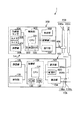
図1は、本発明の一実施例に係る測定装置1の全体構成を示す模式的な外観図である。又、図2は、本実施例の測定装置1の要部の概略機能ブロック図である。本実施例では、測定装置1は、デジタル式の絶縁抵抗計とされる。
Example 1
1. Overall Configuration FIG. 1 is a schematic external view showing the overall configuration of a measuring
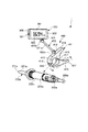
測定装置1は、装置本体100と、一対のテストリード200(200a、200b)と、表示装置300と、取付装置400と、を有する。本実施例の測定装置1は、一対のテストリード200(200a、200b)を用いて装置本体100で求められた測定結果を、一方のテストリード200aに取付装置400によって着脱可能に装着された表示装置300において表示することができる。表示装置300は、取付装置400によって、その表示部302の表示面321をほぼ全方位に向きを変えることが可能とされている。又、表示装置300は、無線通信によって装置本体100との間での情報のやり取りを行う。以下、更に詳しく説明する。
The measuring
2.装置本体
装置本体100は、操作部101、本体表示部102、制御部103、測定部104、第1の無線通信部105、測定端子106などを有する。
2. Device Main Body The device
操作部101には、測定を開始するための測定スイッチ111、電源スイッチと測定目的や測定レンジを切り替えるためのファンクションスイッチとの機能を備えたロータリースイッチ112、コンパレータ機能を用いる際の基準値を選択するためのコンパレータボタン113、本体表示部102のバックライトを点灯させるための点灯ボタン114などが設けられている。ロータリースイッチ112は、その切り換えステージとして、抵抗測定・導通チェック用レンジ〔Ω〕、〔OFF〕レンジ、交流電圧測定用の〔ACV〕レンジ及び定格測定電圧設定レンジを備えている。本実施例では、定格測定電圧設定レンジは、125V、250V、500V、1000Vが選択可能であり、この切り換えに応じて、測定部104の測定電圧発生部から125V、250V、500V、1000Vのいずれかの電圧が測定対象に印加される。操作部101は、各スイッチに割り当てられた機能に応じた信号を制御部103に入力する。
In the
本体表示部102は、装置本体100の筐体である本体ケース107の一側面に設けられている。本実施例では、本体表示部102は、ディジタルディスプレイである液晶ディスプレイで構成される。本実施例では、この液晶ディスプレイとされる本体表示部102は、液晶パネルと、液晶パネルを照明するバックライトとを有する。本体表示部102は、指定された測定目的に応じて、制御部103から入力された信号に従って、測定結果に係る情報を表示する。
The main
制御部103は、装置本体100の各部の動作を統括的に制御する。制御部103には、装置本体100に設けられた操作部101、本体表示部102、測定部104、第1の無線通信部105などが接続されている。制御部102は、演算制御手段としてのCPU131、記憶手段としての電子的なメモリとされるROM132、RAM133などを有して構成される。CPU131は、ROM132に格納され、必要に応じてRAM133に読み出されたプログラムに従って、又必要に応じてRAM133に読み込まれて一時的に保存されたデータなどを用いて、装置本体100の各部を制御する。制御部103は、測定部104のA/D変換部からの電圧データ及び電流データに基づいて、例えば被測定物の電気抵抗の測定値を算出する。そして、制御部103は、測定結果に係る情報として、例えば被測定物の電気抵抗の測定値を本体表示部102で表示させるための信号を、本体表示部102に出力する。又、制御部103は、測定結果に係る情報として、例えば被測定物の電気抵抗の測定値の情報(測定値データ)Dmを、第1の無線通信部105から送信させる。このように、装置本体100は、テストリード200を介して入力された信号に基づいて測定部104によって求められた測定結果に係る情報を、第1の無線通信部105を介して送信する。又、制御部103は、操作部101に表示装置300を操作するためのスイッチ(図示せず)が設けられ、装置本体100で表示装置300を操作できるようになっている場合には、操作部101の操作に応じて第1の無線通信部105から表示装置300の各種の制御信号を送信させることができる。
The
測定部104は、被測定物(被測定電気素子、被測定回路、被測定電気機器など)についての所定の測定目的(パラメータ、物理量)を測定する。測定部104は、被測定物の測定箇所に対して所定の定格測定電圧を印加する測定電圧発生部と、定格測定電圧印加時に測定対象に流れる電流を検出する電流検出部と、定格測定電圧の印加時に測定電圧発生部が印加する電圧と電流検出部にて検出された電流とをそれぞれ所定のサンプリング間隔(例えば、2回/秒)でディジタルデータに変換するA/D変換部と、を備えている。
The measuring
第1の無線通信部105は、制御部103の制御に従い、測定結果に係る情報として、例えば被測定物の電気抵抗の測定値の情報(測定値データ)Dmを送信する。又、上述のように、装置本体100で表示装置300を操作できるようになっている場合には、第1の無線通信部105は、表示装置300の各種の制御信号を送信することができる。そして、第1の無線通信部105から送信された信号は、後述する表示装置300の第2の無線通信部305によって受信される。本実施例では、本体ケース107内に、第1の無線通信部105のアンテナが収容されている。尚、第1、第2の無線通信部105、305は、例えば特定小電力無線の規格に準じて無線通信可能なように構成することができる。その他、ブルートゥース規格、IrDA規格などの利用可能な任意の無線通信規格に準じて無線通信可能なように構成することができる。
Under the control of the
装置本体100には、一対の測定端子106(106a、106b)が設けられている。一方の測定端子はライン側測定端子106aであり、一対のテストリード200(200a、200b)のうち一方のテストリードであるライン側テストリード200aが着脱可能に接続される。他方の測定端子はアース側測定端子106bであり、一対のテストリード200(200a、200b)のうち他方のテストリードであるアース側テストリード200bが着脱可能に接続される。一対のテストリード200(200a、200b)は、一対の測定端子106a、106bを介して測定部104に接続される。
The apparatus
3.テストリード
各テストリード200a、200bは、それぞれ被測定物(その所望の測定箇所或いは接地電位)に接触させられる接触子201a、201b、接触子201a、201bを保持する筐体であるホルダー202a、202b、テストリード200a、200bを装置本体100に連結するケーブル203a、203bなどを有する。ケーブル203a、203bは、接触子201a、201bを装置本体100の測定部104に接続するリード線204a、204bを内包する。ケーブル203a、203bの端部には、リード線204a、204bを測定端子106a、106bに接続可能とするプラグ(図示せず)が形成されており、これを装置本体100に設けられた対応するソケット(図示せず)に着脱可能に取り付けることで、テストリード200a、200bはケーブル203a、203bを介して装置本体100に接続される。
3. Test Leads Each
本実施例では、ホルダー202a、202bは、絶縁材料としての合成樹脂で略円筒形状に成形され、測定者が手で握るのに適した寸法形状とされている。即ち、ホルダー202a、202bは、測定者が測定行う際に握る握り部を構成する。このホルダー202a、202bの長手軸線方向の一方の端部である先端部221a、221bに設けられた穴から該長手軸線方向に沿って露出するようにして、接触子201a、201bがホルダー202a、202bによって保持されている。又、このホルダー202a、202bの長手軸線方向の他方の端部である基端部222a、222bにケーブル203a、203bが連設されている。
In the present embodiment, the
尚、テストリード200としては、種々のタイプのものを用いることができる。例えば、アース側テストリード200bとしては、本実施例のような棒状のピン型テストリードの他、周知のはさみ状のワニ口型テストリードなどを用いてもよい。又、ライン側テストリード200aとして、装置本体100の操作部101の測定スイッチ111と同様の機能を果たす測定スイッチが設けられたものなどを用いてもよい。又、テストリード200は、装置本体100に固定的に接続されていてもよい。
Various types of test leads 200 can be used. For example, as the ground-
4.表示装置
表示装置300は、表示装置操作部301、表示部302、表示装置制御部303、加速度センサ304、第2の無線通信部305などを有する。
4). Display Device The
ここで、図1に示すように、本実施例では、表示装置300の筐体である表示装置ケース306は、正面、背面(裏面)、左右側面、上下側面を有する略平行六面体形状を有する。図1に示す状態における紙面手前側の側面を正面、その反対側の側面を背面、左側の側面を左側面、右側の側面を右側面、上側の側面を上側面、下側の側面を下側面ともいう。正面(又は背面)に対して、左右側面、上下側面はそれぞれ略直交する。表示装置ケース306の正面361のほぼ全面が、後述する表示部302の表示面321とされている。この表示装置ケース306の正面361は一方向に長い略矩形形状であり、その長手方向の一方の端部側の側面である左側面に、表示装置操作部301が設けられている。又、正面と背面との間の距離である奥行は、他の面間(左右側面間、上下側面間)の距離より短く、表示装置ケース306は薄型とされている。
Here, as shown in FIG. 1, in this embodiment, the
表示装置操作部301には、電源スイッチ、必要に応じて表示装置制御部303に各種設定に係る信号を入力する設定スイッチなどが設けられる。表示装置操作部301は、各スイッチに割り当てられた機能に応じた信号を表示装置制御部303に入力する。上述のように、本実施例では、操作部301は、表示装置ケース306の左側面(図1中左側の側面)に設けられている。尚、表示装置300の表示部302上にタッチパネルが設けられ、表示部302における表示とタッチパネルとで操作部301が構成されていてもよい。
The display
表示部302は、表示装置ケース306の一側面である正面361に設けられている。本実施例では、表示部302は、ディジタルディスプレイである液晶ディスプレイで構成される。本実施例では、この液晶ディスプレイとされる表示部302は、液晶パネルと、液晶パネルを照明するバックライトとを有する。上述のように、本実施例では、表示装置ケース306の正面361のほぼ全面が、表示部302の表示面321とされている。表示部302は、指定された測定目的に応じて、表示装置制御部303から入力された信号に従って、測定結果に係る情報を表示する。詳しくは後述するように、表示装置制御部302は、第1、第2の無線通信部105、305を介して装置本体100から送られてきた測定結果に係る情報を表示する。このように、表示装置300は、第1の無線通信部105から送信された情報を第2の無線通信部305を介して受信し、表示部302に測定結果を表示する。尚、本実施例では、表示部302は、カラー液晶ディスプレイとされるが、例えば、予め設定された複数の表示要素を選択的に点灯又は消灯させるモノクロ液晶パネルやカウントLED表示パネルなどであってもよい。本発明は、表示装置300の表示部302の表示方式を何ら限定するものではない。
The
表示装置制御部303は、表示装置300の各部の動作を統括的に制御する。表示装置制御部303には、表示装置300に設けられた表示装置操作部301、表示部302、加速度センサ304、第2の無線通信部305などが接続されている。表示装置制御部102は、演算制御手段としてのCPU331、記憶手段としての電子的なメモリとされるROM332、RAM333などを有して構成される。CPU331は、ROM332に格納され、必要に応じてRAM333に読み出されたプログラムに従って、又必要に応じてRAM333に読み込まれて一時的に保存されたデータなどを用いて、表示装置300の各部を制御する。表示装置制御部303には、第2の無線通信部305が受信した、測定結果に係る情報として、例えば被測定物の電気抵抗の測定値の情報(測定値データ)Dmが入力される。そして、表示装置制御部303は、測定結果に係る情報として、例えば被測定物の電気抵抗の測定値を表示部302で表示させるための信号を表示部302に出力する。又、上述のように、装置本体100で表示装置300を操作できるようになっている場合には、表示装置制御部303には、第2の無線通信部305が受信した、表示装置300の各種の制御信号が入力され、表示装置制御部303はこの制御信号に応じて表示装置300の各部を制御することができる。
The display
表示装置300は、表示装置300の向きに係る情報を検知する検知手段として、重力方向を検知することのできる加速度センサ304を有する。加速度センサ304としては、例えば、静電容量検出方式、ピエゾ抵抗方式、熱検知方式などが知られている、1軸、2軸又は3軸のMEMS(Micro Electro Mechanical System)加速度センサを用いることができる。例えば、アナログ・デバイセズ株式会社製の静電容量検出方式の3軸加速度センサを好適に用いることができる。加速度センサ304は、1個である必要はなく、複数個を単独で、或いは組み合わせて使用することもできる。本実施例では、加速度センサ304は、上記静電容量検出方式の3軸加速度センサとされ、表示装置ケース306の内部に設置された基板(図示せず)に一体に取り付けられている。加速度センサ304の作用については後述して更に詳しく説明する。
The
第2の無線通信部305は、第1の無線通信部105から送信された、測定結果に係る情報として、例えば被測定物の電気抵抗の測定値の情報(測定値データ)Dmを受信する。又、上述のように、装置本体100で表示装置300を操作できるようになっている場合には、第2の無線通信部105は、第1の無線通信部105から送信された、表示装置300の各種の制御信号を受信することができる。第2の無線通信部305は、受信した信号を表示装置制御部303に入力する。本実施例では、表示装置ケース306内に、第2の無線通信部305のアンテナが収容されている。
The second
5.取付装置
取付装置400は、一対のテストリード200(200a、200b)のうちいずれに取り付けてもよいが、通常、ライン側テストリード200aに取り付けることが、表示装置300の表示部302の視認性などの点から好ましい。本実施例では、ライン側テストリード200aに取り付けるものとして説明する。
5. Attachment Device The
図3は、取付装置400をテストリード200aに取り付ける過程を示す模式的な外観図である。又、図4、図5は、それぞれテストリード200aに取り付けられた状態の取付装置400を、テストリード200aの基端部222a側、先端部221a側から見た様子を示す側面図である。又、図6は、図4中の左側から見た取付装置400の側面図である。
FIG. 3 is a schematic external view showing a process of attaching the
取付装置400は、テストリード200aのホルダー202aに着脱可能に固定される固定部401と、固定部401に取り付けられホルダー202aから離間した位置で表示装置300の向きが変更可能なように表示装置300を支持する支持部402と、を有する。
The
本実施例では、固定部401は、テストリード200aのホルダー202aを把持するクリップ(クランプ)とされる。更に説明すると、固定部401は、揺動軸411を中心として互いに揺動可能に連結された第1の揺動部412と第2の揺動部413と、を有する。これら第1、第2の揺動部412、413は、揺動軸411と略直交する方向の一端部である先端部に、互いに当接可能な当接面414、415が設けられ、同方向の他端部である基端部に、操作者によって互いに近づく方向に移動させられる摘み部416、417が設けられている。又、固定部401には、当接面414、415が当接する方向に移動するように第1、第2の揺動部412、413を付勢する付勢手段として、トーションばね418が設けられている。本実施例では、当接面414、415と揺動軸411との間の、第1、第2の揺動部412、413間には、ホルダー202aの長手軸線方向に沿う側面を把持する把持部419が形成されている。特に、本実施例では、揺動軸411と略直交する断面が略半円形の内周面が第1、第2の揺動部412、413に形成されている。この略半円形の断面は、当接面414、415が当接した状態で略円形となる。又、摘み部416、417を操作して当接面414、415を離間させると、ホルダー202aがその長手軸線方向と略直交する方向に移動して当接面414、415の間を通過できるようになっている。これにより、ホルダー202aの先端部221aと基端部222aとの間の中間部223aの適当な位置の側面を、把持部419によって適当な圧力で圧迫して、固定部401をテストリード200aに着脱可能に固定することができる。
In this embodiment, the fixing
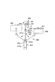
本実施例では、支持部402は、ロッド部421(421a、421b)と、可動ジョイント部422(422a、422b、422c)とを有する多関節アームとされる。更に説明すると、図5に良く示されるように、固定部401側から表示装置300に向けて、第1の可動ジョイント部422a、第1のアーム部421a、第2の可動ジョイント部422b、第2のアーム部421b、第3の可動ジョイント部422cが設けられている。図7により詳細に示すように、本実施例では、第1、第2、第3の可動ジョイント部422a、422b、422cはそれぞれ、略球形のボール部423と、このボール部423を摺動可能に収容し保持するボール保持部424と、で構成される。
In the present embodiment, the
特に、本実施例では、第1の可動ジョイント部422aを構成するボール保持部424は、固定部401の第1の揺動部412の一側面412aに固定(一体成型)されている。又、第1のアーム部421aの長手軸線方向において固定部401側の端部に第1の可動ジョイント部422aを構成するボール部423が固定(一体成型)され、表示装置300側の端部に第2の可動ジョイント部422bを構成するボール保持部424が固定(一体成型)されている。同様に、第2のアーム部421bの長手軸線方向において固定部401側の端部に第2の可動ジョイント部422bを構成するボール部423が固定(一体成型)され、表示装置300側の端部に第3の可動ジョイント部422cを構成するボール保持部424が固定(一体成型)されている。そして、第3の可動ジョイント部422cを構成するボール部423は、表示装置ケース306の背面362に固定(一体成型)されている。本実施例では、第1、第2のアーム部421a、421b、第1、第2、第3の可動ジョイント部422a、422b、422c、固定部401の少なくとも第1、第2の揺動部412、413、表示装置300の少なくとも表示装置ケース306は、合成樹脂で形成されている。
In particular, in this embodiment, the
図7に示すように、各可動ジョイント部422において、ボール保持部424は、アーム部421(又は固定部401)との連結部とは反対側に開口部424aが形成された、略球形の内周面424d及び外周面424eを有する形状とされている。ボール部423をボール保持部424の開口部424aからボール保持部424の内周面424d側に押し込むことで、ボール部423とボール保持部424とは弾発的に係合(スナップフィット)する。ボール部423は、ボール保持部424に収容された状態でボール保持部424に対して相対移動(摺動)することができる。ボール保持部424の内周面424dの形状は、自然状態(弾性変形されていない状態)でボール部423の外周面423aの寸法よりも小さくされているため、ボール部423の外周面423aとボール保持部424の内周面424dとが摩擦係合して、互いの相対位置を所望の位置で保持することができる。この摩擦係合による保持力は、取付装置400によって支持された表示装置300を所定の位置で保持できる程度に強く、当該可動ジョイント部422が動くことで操作者が比較的容易に表示装置300の位置や向きを変更できる程度に弱く設定されている。
As shown in FIG. 7, in each movable
又、ボール保持部424には、上記開口部424a側からアーム部421(又は固定部401)との連結部側に向けて、対向する位置に切り込み424b、424cが形成されている。この切り込み424b、424cは、その内側をアーム部421(又は表示装置300との連結部)が通過又は摺動できるような寸法に形成されている。そのため、ボール部423に隣接するアーム部421(又は表示装置300との連結部)の軸線方向A1は、ボール保持部424に隣接するアーム部421(又は固定部401との連結部)の軸線方向A2に対して略直角方向まで偏向させることができる。又、例えば上記軸線方向A1、A2を同一直線上とした状態で、ボール部423とボール保持部424とは、上記軸線方向A1、A2の周りを回転することができる。そのため、各可動ジョイント部422について、上記軸線方向A1上の各位置は、ボール保持部424の略中央を通り上記軸線方向A2と略直交する平面よりも当該各位置側において、略半球状に自由に移動させることができる。
Further, the
従って、上述のような各可動ジョイント部422の可動範囲に応じた支持部402全体としての可動範囲内で、自由に表示装置300を移動させることができる。これにより、表示装置300を、例えば図4、図5に示すようにテストリード200aのホルダー202aの長手軸線方向と略直交する平面上を測定者に近い位置から遠い位置に向けて又はその反対に向けて移動させたり、例えば図6に示すようにテストリード200の長手軸線方向に沿って測定者に近い位置から遠い位置に向けて又はその反対に向けて移動させたりすることができる。又、本実施例では、各可動ジョイント部422の可動範囲が上述のような可動範囲とされていることで、支持部402は、表示装置300の表示部302の表示面321を略全方位に配向させることができる。更に、本実施例では、各可動ジョイント部422の可動範囲が上述のような可動範囲とされていることで、第3の可動ジョイント部422c(第2のアーム部421と表示装置300との連結部)が配置された各位置において、表示装置300は、横向き、縦向き、及びその間の向きに自由に回転させることができる。
Therefore, the
尚、各アーム部421の長さや可動ジョイント部422の数は、所望の可動範囲に応じて適宜選択することができる。例えば、図8に示すように、支持部402は、固定部401に固定された第1の可動ジョイント部422aを構成するボール保持部424と、第1の可動ジョイント部422aを構成するボール部423と第2の可動ジョイント部422bを構成するボール保持部424とを両端部に備えた1つのアーム部421と、表示装置ケース306の背面362に固定された第2の可動ジョイント部422bを構成するボール部423と、を有する構成としてもよい。又、固定部401と支持部402との連結部及び/又は支持部402と表示装置300との連結部に可動ジョイント部422を設けずに、そこを固定することもできる。但し、表示装置300の向きの自由度を向上する観点から、支持部402は、固定部401との連結部及び表示装置300との連結部のうち少なくとも一方が可動であることが好ましい。該少なくとも一方の連結部は、例えば本実施例における上記可動ジョイント部422で構成することができる。又、本実施例では、第2のアーム部421bが第1のアーム部421aよりも短くされているが、同じ長さであってもよいし、第1のアーム部421aの方が短くされていてもよい。
In addition, the length of each
又、本実施例では、支持部402は多関節アームとしたが、これに限定されるものではなく、表示装置300を所望の可動範囲で移動させてその向きや位置を変更できればよい。例えば、図9に示すように、支持部402としてランプの支持部材などとして周知のフレキシブルチューブ(フレキシブルアーム)を用いてもよい。この場合も、支持部402は、固定部401との連結部及び表示装置300との連結部のうち少なくとも一方が可動であることが好ましい。但し、フレキシブルチューブは一般に本実施例の多関節アームよりも自由に屈曲(湾曲)させて表示装置300の向きや位置を変更できるので、上記各連結部がいずれも固定されている場合でも、表示装置300の向きの自由度は比較的高い。
In this embodiment, the
又、本実施例では、固定部401はクリップとしたが、これに限定されるものではなく、表示装置300を所望の位置に保持できるように支持部402をテストリード200aに固定できればよい。例えば、図10に示すように、テストリード200aのホルダー202aに弾発的に係合(スナップフィット)する、一部切り欠き環状の合成樹脂による成型品などとされていてもよい。
In this embodiment, the fixing
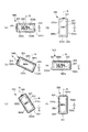
6.表示の回転
本実施例では、上述のように、表示装置300の向きを変えることができ、表示装置300の表示部302は、その一辺が重力方向の上側を向いたり、下側を向いたり、或いはその間の方向を向いたりする。しかし、表示装置300の表示部302における表示内容322自体は、重力方向に対して所定の向き、或いは該所定の向きに近い向きになっていることが、視認性の観点から好ましい。
6). In this embodiment, as described above, the direction of the
そこで、本実施例では、表示装置300は、前述のように、表示装置300の向きに係る情報を検知する検知手段としての加速度センサ304を有する。又、表示装置300は、加速度センサ304の検知結果に基づいて表示部302における表示内容322の向きを指示する指示手段を有する。本実施例では、表示装置制御部303が指示手段としての機能を有する。
Therefore, in the present embodiment, the
前述のように、本実施例では、加速度センサ304は、静電容量検出方式の3軸加速度センサとされ、表示装置ケース306の内部に設置された基板に一体に取り付けられている。本実施例では、表示装置ケース306の短手方向(上下側面と直交する方向)をX軸、長手方向(左右側面と直交する方向)をY軸、表示装置ケース306の正面361(表示面321)と直交する方向をZ軸とする。加速度センサ304は、X軸、Y軸、Z軸の重力方向に対する角度に対応した信号を出力し、表示装置制御部303に入力する。表示装置制御部303では、重力方向とX軸、Y軸、Z軸とのなす角度を算出し、その結果から表示装置300の向き(姿勢)を判断することができる。
As described above, in the present embodiment, the
ここで、図11を参照して、表示部302の長手方向の対向する2辺を長辺302a、302bとし、この長辺302a、302bと直交する短手方向の対向する2辺を短辺302c、302dとする。又、重力方向を表示部302の表示面321に射影した方向(以下「重力射影方向」ともいう。)を図中矢印Gで示す。又、表示面321に沿って長辺302a、302b、短辺302c、302dから表示部302の外側に向けて略垂直に伸ばした直線の方向をそれぞれ法線方向(図中破線N)とよぶ。
Here, referring to FIG. 11, two opposite sides in the longitudinal direction of
このとき、表示装置制御部303は、加速度センサ304の検知結果から、例えば図11(a)、(e)に示すように長辺302a、302bの法線方向Nのいずれかが重力射影方向Gの上側又は上側に近い方向を向いている状態(横向き)であるのか、例えば図11(d)、(f)に示すように短辺302a、302bの法線方向Nが重力射影方向の上側又は上側に近い方向を向いている状態(縦向き)であるのかを判断することができる。そして、表示装置制御部303は、加速度センサ304の検知結果に基づいて、表示部302における表示内容322の向きを変更するように、表示部302に制御信号を出力する。
At this time, from the detection result of the
尚、本実施例では、加速度センサ304の検知結果に基づいて、重力加速度が検出できればよいので、表示装置制御部303は、表示装置300に対して瞬間的にある方向にかかる運動加速度は無視するようになっている。
In this embodiment, it is only necessary that the gravitational acceleration can be detected based on the detection result of the
例えば、表示装置制御部303は、正規の向きに見た場合の表示内容322の上側が、重力射影方向Gの上側を向くように表示部302における表示内容322の向きを変えることができる。この場合、例えば図11(a)に示すように重力射影方向Gの上側に位置する長辺302aを向いていた表示内容322の上側が、図11(b)に示すように、表示部302の向きが変わるにつれて常に重力射影方向Gの上側を向くように向きが変更される。このとき、表示装置制御部303は、表示内容322が表示部302内に収まるように、適宜その大きさを変更することができる。
For example, the display
又、例えば、表示装置制御部303は、正規の向きに見た場合の表示内容322の上側が、重力射影方向Gと直交する方向よりも重力射影方向Gの上側に近い方向を向くように、表示部302における表示内容322の向きを変えることができる。例えば、正規の向きに見た場合の表示内容322の上側が、表示部302の基準となる対向する2辺(例えば長辺302a、302b)と、この2辺と直交する対向する他の2辺とのうち、その法線方向Nがより重力射影方向Gの上側に近い方向を向いている辺を向くように、表示部302における表示内容322の向きを変えることができる。この場合、例えば図11(a)に示すように重力射影方向Gの上側に位置する長辺302aを向いていた表示内容322の上側は、表示部302の向きが変わってもすぐには方向が変更されず、例えば図11(c)に示すように一方の短辺302cの法線方向Nがより重力射影方向Gの上側に近い向き(即ち、重力射影方向Gに対し45度以下)になった際に、その短辺302c側を向くように向きが変更される。
Further, for example, the display
又、例えば、表示装置制御部303は、正規の向きに見た場合の表示内容322の上側が、基準となる対向する2辺(例えば長辺302a、302b)のうち、その法線方向Nがより重力射影方向Gの上側に近い方向を向いている辺を向くように、表示部302おける表示内容322の向きを変えることができる(図11(a)、(e))。この場合、図11(d)、(f)に示す状態から図11(a)に示す状態に近づくように表示部302が回転すると、表示内容322は図11(a)に示す向きとなり、逆に図11(e)に示す状態に近づくように表示部302が回転すると、表示内容322は図11(e)に示す向きとなる。図11(d)、(f)の状態における表示内容322の向きは、図11(a)、(e)のいずれに示す向きとしてもよい。
Further, for example, the display
尚、表示内容の正規の向きとは、表示内容をそれが示す本来の情報を認識できるように、社会通念上の本来の上側が上側になり、下側が下側になるように表示した場合の向きである。この場合の上下は、厳密な垂直方向のみを意味するものではない。表示内容が文字情報であれば、社会通念上、その構成する文字の上側が上側になり、下側が下側になるように表示した場合の向きである。但し、表示内容は文字情報に限定されるものではなく、測定結果を示すものであれば、指針式メータなどの任意の形態であってよい。又、測定結果と共に、当該測定機能に対応する各種設定情報なども表示するのであれば、通常、その表示も同じ向きに表示されるようにする。 In addition, the normal orientation of the display content is the case where the original upper side in social convention is the upper side and the lower side is the lower side so that the original information indicated by the display content can be recognized. The direction. The upper and lower in this case does not mean only a strict vertical direction. If the display content is character information, it is the direction when the characters are displayed such that the upper side is the upper side and the lower side is the lower side for social wisdom. However, the display content is not limited to character information, and may be any form such as a pointer-type meter as long as it indicates a measurement result. If various setting information corresponding to the measurement function is displayed together with the measurement result, the display is usually displayed in the same direction.
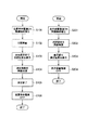
7.動作
図12は、測定を行う際の測定装置1の動作の概略手順の一例を示す。装置本体100において、電源がONとされ、所望の測定目的・測定レンジにセットされ、又後述するように表示装置300の電源がONとされている場合には表示装置300との無線接続が確立される(S101)。その後、測定スイッチ111が押されることで、測定が開始される(S102)。そして、制御部103は、測定結果に係る情報を本体表示部102に出力して、本体表示部102に測定結果を表示させる(S103)。それと共に、制御部103は、測定結果に係る情報を第1の無線通信部105から送信させる(S104)。その後、測定スイッチ111が離されることで、測定が終了(測定値がホールド)される(S105)。その後、装置本体100の電源がOFFとされる(S106)。
7). Operation FIG. 12 shows an example of a schematic procedure of the operation of the
一方、表示装置300において、電源がONとされ、上述のように装置本体100の電源がONとされている場合には、装置本体100との無線接続が確立される(S201)。このとき、測定者は、表示装置300の向きや位置を、表示部302の視認性やテストリード200aの操作性などに鑑みて適宜変更することができる。その後、表示装置制御部303に第2の無線通信部305が受信した測定結果に係る情報が入力される(S202)。そして、表示装置制御部303は、測定結果に係る情報を表示部302に出力して、表示部302に測定結果を表示させる(S203)。このとき、表示装置制御回路303は、加速度センサ304からの信号に応じて、表示内容322の向きや大きさを適宜変更して表示部302に表示させることができる。その後、表示装置300の電源がOFFとされる(S204)。
On the other hand, in the
8.作用効果
以上のように、本実施例によれば、装置本体100の本体表示部102を見なくても、表示装置300の表示部302を見ることで測定値が確認できる。そのため、より確実に被測定物にテストリード200を接触させながら、測定を行うことができる。そのため、測定結果の信頼性と作業性の向上を図ることができる。又、装置本体100の本体表示部102と測定箇所とでの視線の往復が低減され、測定時間の短縮を図ることができる。又、表示装置300は、取付装置400によって既存のテストリード200にも取り付け可能であり、表示装置300を様々なテストリード200に流用することができる。又、使用する環境により、表示装置300の表示部302を測定者の見やすい位置に動かしたり向きを変えたりする(例えば反転させる)ことが可能であり、作業性の向上を図ることができる。
8). As described above, according to the present embodiment, the measured value can be confirmed by looking at the
実施例2
次に、本発明に係る測定装置の他の実施例について説明する。本実施例の測定装置の基本的な構成及び動作は、実施例1のものと同じである。従って、実施例1のものと同一又はそれに相当する機能、構成を有する要素には同一符号を付して、詳しい説明は省略する。
Example 2
Next, another embodiment of the measuring apparatus according to the present invention will be described. The basic configuration and operation of the measuring apparatus of the present embodiment are the same as those of the first embodiment. Accordingly, elements having the same functions or configurations as those of the first embodiment are denoted by the same reference numerals, and detailed description thereof is omitted.
図13は、本実施例における表示装置300が取付装置400によって支持されている様子を図5と同様の方向から見た側面図である。又、図14は、本実施例の測定装置1の要部の概略機能ブロック図である。
FIG. 13 is a side view of the state in which the
本実施例では、表示装置300は、表示部302の表示面321とは反対側を照明するライト307を有する。ライト307は、表示装置ケース306の背面362に設けられており、表示面321と略直交する方向において表示面321が向いている方向とは反対方向の所定範囲を照明する。ライト307は、好ましくは、取付装置400によってテストリード200aに取り付けられた表示装置300の位置からテストリード200aの接触子201aの位置を十分の明るさで照明できるように構成されている。
In the present embodiment, the
ライト307の光源としては、例えば、LED、白熱灯などを用いることができる。小型で十分に高輝度のものが入手できることからLEDが好ましい。照射光に指向性を持たせるために、ライト307は、光源に加えて遮光手段やレンズなどの光学部品を有していてもよい。 As the light source of the light 307, for example, an LED or an incandescent lamp can be used. LEDs are preferred because they are small and have sufficiently high brightness. In order to give directivity to the irradiation light, the light 307 may include an optical component such as a light shielding unit or a lens in addition to the light source.
本実施例では、表示装置300の操作部301には、ライト307の点灯又は消灯を切り替えるスイッチが設けられている。又、装置本体100の操作部101に同様の機能を有するスイッチを設け、装置本体100側から操作できるようにしてもよい。
In the present embodiment, the
表示装置300は、その向きや位置を変更できるので、表示部302の視認性と共に、ライト307による照明方向をも鑑みてその向きや位置を変更することで、暗い測定箇所を適切にライト307によって照明することができる。
Since the
又、本実施例では、表示装置300は、表示部302の表示面321とは反対側を撮影するカメラ308を有する。カメラ308は、表示装置ケース306の背面362に設けられており、表示面321と略直交する方向において表示面321が向いている方向とは反対方向の所定範囲を撮影する。カメラ308は、好ましくは、取付装置400によってテストリード200aに取り付けられた表示装置300の位置からテストリード200aの接触子201aの位置を十分の視野で撮影できるように構成されている。
In the present embodiment, the
カメラ308としては、レンズ、撮像素子としてのCCDやCMOS、撮像素子によって得られた信号から画像情報を生成する画像処理回路などを備えた、利用可能な任意の構成のデジタルカメラを使用することができる。カメラ308は、焦点合わせを特に必要としないように十分な被写界深度を有するように構成することができるが、焦点合わせが可能なように構成してもよい。
As the
本実施例では、表示装置300は、カメラ308により撮影された画像を表示部302にライブビュー表示することができる。即ち、表示装置制御部303は、カメラ308によって撮影された画像を、即時的に表示部302においてビデオ表示させる。ここで、即時的に表示するとは、当業者には容易に理解さるように、カメラ308の画像処理回路における信号処理時間や表示部302に表示させるための信号処理時間分の遅延がある場合も含む意味である。
In this embodiment, the
又、本実施例では、表示装置300は、カメラ308により撮影された画像を拡大して表示部302に表示できるようになっている。ここで、拡大して表示するとは、テストリード200aに取り付けられた表示装置300によってテストリード200aの接触子201aの近傍を撮影した場合に、一般的な使用方法に従ってテストリード200aを持っている測定者がその接触子201aの近傍を肉眼で見た場合よりも大きく視認できればよい。測定者が適宜拡大率を変更できるように、カメラ308にズームイン、ズームアウト機能を持たせてもよい。カメラ308は、対象を光学的に拡大して撮影できるようになっていてもよいし、対象を撮影した画像を信号処理することで拡大するようになっていてもよい。
In the present embodiment, the
そして、本実施例では、表示装置300は、図15に示すように、装置本体100から送信された測定結果Mと、カメラ308により撮影された画像Iとを、表示部302において同時に表示することができる。
In this embodiment, the
又、好ましくは、装置本体100及び/又は表示装置300に、カメラ308により撮影された特定の画像に係る情報を、特定の測定結果に係る情報と関係付けて記憶する記憶部500を設けることができる(図14)。この記憶部500としては、フラッシュメモリのような不揮発性メモリ、ハードディスクなどの磁気記録媒体などを好適に用いることができる。又、この記憶部500は、装置本体100や表示装置300に対して着脱自在(リムーバブル)な記憶媒体であることが、その後の画像情報や測定結果情報の利用のしやすさから好ましい。但し、これに限定されるものではなく、装置本体100や表示装置300に、別途外部機器(パーソナルコンピュータ)などとの間での通信を可能とするインターフェース部(図示せず)を設けて、このインターフェース部を介して記憶部500の情報を外部機器から読み取ることができるようにしてもよい。
Preferably, the device
本実施例では、表示装置300の操作部301には、カメラ308による撮影の開始又は停止を指示するスイッチ、必要に応じてカメラ308の焦点合わせスイッチ、ズームイン・ズームアウトスイッチが設けられている。又、装置本体100の操作部101に同様の機能を有するスイッチを設け、装置本体100側から操作できるようにしてもよい。
In this embodiment, the
図16は、表示装置300のカメラ308を用いて測定を行う際の表示装置300の動作の概略手順の一例を示す。表示装置300において、電源がONとされ、前述のように装置本体100の電源がONとされている場合には装置本体100との無線接続が確立される(S301)。その後、例えば表示装置300の操作部301に設けられたカメラ308の撮影開始スイッチが押されることで、カメラ308による撮影が開始され、表示部302におけるライブビュー表示が開始される(S302)。そして、表示装置制御部303に第2の無線通信部305が受信した測定結果に係る情報が入力される(S303)。表示装置制御部303は、測定結果に係る情報を表示部302に出力して、表示部302においてライブビュー表示と共に測定結果を表示させる(S304)。このとき、表示装置制御回路303は、加速度センサ304からの信号に応じて、表示内容322(測定結果とライブビュー表示)の向きや大きさを適宜変更して表示部302に表示させることができる。その後、表示装置300の電源がOFFとされる(S305)。
FIG. 16 shows an example of a schematic procedure of the operation of the
又、図17は、表示装置300のカメラ308を用いて測定結果と画像とを同時保存する際の表示装置300の動作の概略手順の一例を示す。図17中の手順S401〜S404は、図16中の手順S301〜304と同じである。その後、表示装置制御回路303は、装置本体100において測定スイッチ111が離されることで測定値がホールドされたり、或いは測定値が安定することで自動的に測定値がホールドされたりしたか否かを判断する(S405)。測定値がホールドされたか否かは、装置本体100から第1、第2の無線通信部105、305を介してその旨を示す情報が入力されることで、表示装置制御部303が判断できるようになっている。そして、測定値がホールドされていない場合は、測定値の表示の更新が繰り返される。一方、表示装置制御部303は、測定値がホールドされたと判断した場合は、その測定値と関係付けて、そのときにカメラ308によって撮影された画像を、静止画像情報として記憶部500に記憶させる(S406)。その後、表示装置300の電源がOFFとされる(S407)。ここで、表示装置300の記憶部500と共に又はこれに代えて装置本体100の記憶部500に測定値と画像とを関係付けて記憶させるように構成されている場合には、表示装置制御部303は、上記静止画像情報を第2の無線通信部305から送信させる。そして、装置本体100の第1の無線通信部105でこの情報を受信して、制御部103が装置本体100の記憶部500に、上記静止画像情報をホールドされた測定値と関係付けて記憶させることができる。
FIG. 17 shows an example of a schematic procedure of the operation of the
尚、測定値と関係付けて記憶する画像情報は静止画像情報に限定されるものではなく、例えばホールドされた測定値が得られた時点を含む所定期間(その時点の前又は後の所定期間でもよい)の動画(ビデオ)情報を記憶してもよい。 Note that the image information stored in association with the measurement value is not limited to still image information. For example, a predetermined period including a time point at which a held measurement value is obtained (even a predetermined period before or after that time point). (Good) video (video) information may be stored.
以上のように、本実施例によれば、暗い環境でも、ライト307を点灯させることで、より確実にテストリード200を被測定物に接触させることが可能になり、測定結果の信頼性と作業性の向上を図ることができる。又、カメラ308でテストリード200の被測定物への接触箇所を映し出すことで、測定箇所の画像と測定値との同時保存が可能であり、測定後でも測定箇所に対する測定値を簡単に確認することができる。又、カメラ308によってテストリード200の被測定物への接触箇所を拡大して映すことで、例えば小さい電気部品などの被測定物へのテストリード200の接触をより確実にして、測定結果の信頼性と作業性の向上を図ることができる。
As described above, according to the present embodiment, the
尚、本実施例では、表示装置300は、ライト307とカメラ308との両方を有している。これにより、ライト307で照明しつつカメラ308で撮影することで、暗い環境における作用性と測定結果の信頼性は飛躍的に向上する。但し、ライト307とカメラ308は、これらのいずれか一方のみを有していてもよい。この場合、ライト307、カメラ308のそれぞれに対応した上記同様の効果を得ることができる。
In the present embodiment, the
その他
尚、上述の実施例では、測定器は絶縁抵抗計であるものとして説明したが、本発明はこれに限定されるものではない。例えば、測定器はLCRメータ、デジタルマルチメータ、テスタなどであってもよく、測定目的は電流、電圧、静電容量などであってもよい。又、装置本体はアナログ式のテスタや絶縁抵抗計であってもよく、測定結果をA/D変換したデータを表示装置に送信することで上述の実施例と同様の効果が得られる。
Others In the above-described embodiments, the measuring instrument is described as an insulation resistance meter, but the present invention is not limited to this. For example, the measuring device may be an LCR meter, a digital multimeter, a tester, or the like, and the measurement purpose may be current, voltage, capacitance, or the like. The apparatus main body may be an analog tester or an insulation resistance meter, and the same effect as in the above-described embodiment can be obtained by transmitting data obtained by A / D conversion of the measurement result to the display device.
又、上述の実施例では、測定結果は測定値であるものとして説明したが、例えばコンパレータ機能を有する測定装置の場合、測定結果は測定値と基準値との比較による判定結果(測定値が上限値を超える値であるか否か、下限値未満であるか否か、下限値以上且つ上限値以下であるか否かなど)であってもよい。 In the above-described embodiments, the measurement result is described as a measurement value. However, for example, in the case of a measurement apparatus having a comparator function, the measurement result is a determination result by comparing the measurement value with a reference value (the measurement value is the upper limit). It may be a value exceeding a value, whether it is less than a lower limit value, whether it is a lower limit value or more and an upper limit value or less).
1 測定装置
100 装置本体
105 第1の無線通信部
200 テストリード
202 ホルダー
300 表示装置
302 表示部
305 第2の無線通信部
400 取付装置
401 固定部
402 支持部
DESCRIPTION OF
Claims (16)
被測定物に接触させられる接触子と、前記接触子を保持するホルダーと、を備え、ケーブルを介して前記装置本体に接続されるテストリードと、
表示部と、第2の無線通信部と、を備えた表示装置と、
前記ホルダーに着脱可能に固定される固定部と、前記固定部に取り付けられ前記ホルダーから離間した位置で前記表示装置の向きが変更可能なように前記表示装置を支持する支持部と、を備えた取付装置と、
を有し、
前記装置本体は、前記テストリードを介して入力された信号に基づいて前記測定部によって求められた測定結果に係る情報を、前記第1の無線通信部を介して送信し、
前記表示装置は、前記第1の無線通信部から送信された情報を前記第2の無線通信部を介して受信し、前記表示部に前記測定結果を表示することを特徴とする測定装置。 An apparatus main body comprising a measurement unit and a first wireless communication unit;
A contact that is brought into contact with an object to be measured; a holder that holds the contact; and a test lead that is connected to the apparatus main body via a cable;
A display device comprising: a display unit; and a second wireless communication unit;
A fixing portion that is detachably fixed to the holder; and a support portion that supports the display device so that the orientation of the display device can be changed at a position that is attached to the fixing portion and spaced from the holder. A mounting device;
Have
The apparatus main body transmits information on a measurement result obtained by the measurement unit based on a signal input via the test lead, via the first wireless communication unit,
The display device receives information transmitted from the first wireless communication unit via the second wireless communication unit, and displays the measurement result on the display unit.
Priority Applications (1)
| Application Number | Priority Date | Filing Date | Title |
|---|---|---|---|
| JP2012148947A JP6029357B2 (en) | 2012-07-02 | 2012-07-02 | measuring device |
Applications Claiming Priority (1)
| Application Number | Priority Date | Filing Date | Title |
|---|---|---|---|
| JP2012148947A JP6029357B2 (en) | 2012-07-02 | 2012-07-02 | measuring device |
Publications (2)
| Publication Number | Publication Date |
|---|---|
| JP2014010124A true JP2014010124A (en) | 2014-01-20 |
| JP6029357B2 JP6029357B2 (en) | 2016-11-24 |
Family
ID=50106934
Family Applications (1)
| Application Number | Title | Priority Date | Filing Date |
|---|---|---|---|
| JP2012148947A Expired - Fee Related JP6029357B2 (en) | 2012-07-02 | 2012-07-02 | measuring device |
Country Status (1)
| Country | Link |
|---|---|
| JP (1) | JP6029357B2 (en) |
Cited By (2)
| Publication number | Priority date | Publication date | Assignee | Title |
|---|---|---|---|---|
| JP2018087792A (en) * | 2016-11-30 | 2018-06-07 | 日置電機株式会社 | Portable terminal and processing program |
| WO2019241280A1 (en) * | 2018-06-11 | 2019-12-19 | Tektronix, Inc. | Test-and-measurement probe having a touchscreen |
Citations (8)
| Publication number | Priority date | Publication date | Assignee | Title |
|---|---|---|---|---|
| JPS6297962U (en) * | 1985-12-10 | 1987-06-22 | ||
| JPH11183523A (en) * | 1997-12-25 | 1999-07-09 | Matsushita Electric Ind Co Ltd | Oscilloscope with remote display |
| US20030137310A1 (en) * | 2002-01-22 | 2003-07-24 | Thomas Holzel | Remote viewing screen for test instrument |
| JP2004020361A (en) * | 2002-06-17 | 2004-01-22 | Hioki Ee Corp | Portable tester with light and its operating method |
| US20040239308A1 (en) * | 2003-05-30 | 2004-12-02 | David Fazzina | Multimeter having off-device display device and selection device |
| WO2010108089A2 (en) * | 2009-03-19 | 2010-09-23 | Perceptron, Inc. | Display device for measurement tool |
| JP2013213693A (en) * | 2012-03-30 | 2013-10-17 | Hioki Ee Corp | Measurement device |
| JP2013212184A (en) * | 2012-03-30 | 2013-10-17 | Toshiba Corp | Ultrasonic diagnosis device |
-
2012
- 2012-07-02 JP JP2012148947A patent/JP6029357B2/en not_active Expired - Fee Related
Patent Citations (9)
| Publication number | Priority date | Publication date | Assignee | Title |
|---|---|---|---|---|
| JPS6297962U (en) * | 1985-12-10 | 1987-06-22 | ||
| JPH11183523A (en) * | 1997-12-25 | 1999-07-09 | Matsushita Electric Ind Co Ltd | Oscilloscope with remote display |
| US20030137310A1 (en) * | 2002-01-22 | 2003-07-24 | Thomas Holzel | Remote viewing screen for test instrument |
| JP2004020361A (en) * | 2002-06-17 | 2004-01-22 | Hioki Ee Corp | Portable tester with light and its operating method |
| US20040239308A1 (en) * | 2003-05-30 | 2004-12-02 | David Fazzina | Multimeter having off-device display device and selection device |
| US20070035317A1 (en) * | 2003-05-30 | 2007-02-15 | David Fazzina | Multimeter having off-device display device and selection device |
| WO2010108089A2 (en) * | 2009-03-19 | 2010-09-23 | Perceptron, Inc. | Display device for measurement tool |
| JP2013213693A (en) * | 2012-03-30 | 2013-10-17 | Hioki Ee Corp | Measurement device |
| JP2013212184A (en) * | 2012-03-30 | 2013-10-17 | Toshiba Corp | Ultrasonic diagnosis device |
Cited By (5)
| Publication number | Priority date | Publication date | Assignee | Title |
|---|---|---|---|---|
| JP2018087792A (en) * | 2016-11-30 | 2018-06-07 | 日置電機株式会社 | Portable terminal and processing program |
| WO2019241280A1 (en) * | 2018-06-11 | 2019-12-19 | Tektronix, Inc. | Test-and-measurement probe having a touchscreen |
| CN112534275A (en) * | 2018-06-11 | 2021-03-19 | 特克特朗尼克公司 | Test and measurement probe with touch screen |
| JP2021527215A (en) * | 2018-06-11 | 2021-10-11 | テクトロニクス・インコーポレイテッドTektronix,Inc. | Test measurement probe with touch screen |
| US11719721B2 (en) | 2018-06-11 | 2023-08-08 | Tektronix, Inc. | Test and measurement probe having a touchscreen |
Also Published As
| Publication number | Publication date |
|---|---|
| JP6029357B2 (en) | 2016-11-24 |
Similar Documents
| Publication | Publication Date | Title |
|---|---|---|
| CN107534734B (en) | Humidity measurement device with thermal imaging capability and related methods | |
| JP6649503B2 (en) | Wireless positioning pen with pressure-sensitive tip | |
| JP2012235997A (en) | Endoscope | |
| WO2010108089A2 (en) | Display device for measurement tool | |
| JP2013088287A (en) | Micrometer | |
| US20030137310A1 (en) | Remote viewing screen for test instrument | |
| JP7402597B2 (en) | Test measurement probe with touch screen | |
| JP6029357B2 (en) | measuring device | |
| CN109154494A (en) | Probe and Probe clip with Anti-bumping protection | |
| JP6136090B2 (en) | Electronic device and display device | |
| US10451450B2 (en) | External device for measuring instrument | |
| JP2009282493A (en) | Microscope device with illumination means | |
| CN106331437B (en) | Image pickup apparatus | |
| JP2017142857A (en) | Input device | |
| JP2015224947A (en) | Optical coordinate measurement device | |
| US11789038B2 (en) | Probe, measuring system and method for applying a probe | |
| JP6717393B2 (en) | Electronics | |
| JP2010133798A (en) | Digital multimeter | |
| GB2049205A (en) | Electric potential detector | |
| JP6940746B2 (en) | Detector and surface roughness measuring machine | |
| KR101011828B1 (en) | Mobile terminal having gravity sensor and display method using the same | |
| JP2007309815A (en) | Lens meter | |
| KR102092656B1 (en) | Probe apparatus and optical microscopy comprising the same | |
| JPH11183523A (en) | Oscilloscope with remote display | |
| KR102296457B1 (en) | Electronic measuring instrument |
Legal Events
| Date | Code | Title | Description |
|---|---|---|---|
| A621 | Written request for application examination |
Free format text: JAPANESE INTERMEDIATE CODE: A621 Effective date: 20150527 |
|
| A977 | Report on retrieval |
Free format text: JAPANESE INTERMEDIATE CODE: A971007 Effective date: 20160427 |
|
| A131 | Notification of reasons for refusal |
Free format text: JAPANESE INTERMEDIATE CODE: A131 Effective date: 20160510 |
|
| A521 | Request for written amendment filed |
Free format text: JAPANESE INTERMEDIATE CODE: A523 Effective date: 20160621 |
|
| TRDD | Decision of grant or rejection written | ||
| A01 | Written decision to grant a patent or to grant a registration (utility model) |
Free format text: JAPANESE INTERMEDIATE CODE: A01 Effective date: 20161011 |
|
| A61 | First payment of annual fees (during grant procedure) |
Free format text: JAPANESE INTERMEDIATE CODE: A61 Effective date: 20161018 |
|
| R150 | Certificate of patent or registration of utility model |
Ref document number: 6029357 Country of ref document: JP Free format text: JAPANESE INTERMEDIATE CODE: R150 |
|
| R250 | Receipt of annual fees |
Free format text: JAPANESE INTERMEDIATE CODE: R250 |
|
| LAPS | Cancellation because of no payment of annual fees |