JP2014009019A - Packaging material and packaging body - Google Patents
Packaging material and packaging body Download PDFInfo
- Publication number
- JP2014009019A JP2014009019A JP2012147855A JP2012147855A JP2014009019A JP 2014009019 A JP2014009019 A JP 2014009019A JP 2012147855 A JP2012147855 A JP 2012147855A JP 2012147855 A JP2012147855 A JP 2012147855A JP 2014009019 A JP2014009019 A JP 2014009019A
- Authority
- JP
- Japan
- Prior art keywords
- corner
- protection member
- container body
- packed
- fitted
- Prior art date
- Legal status (The legal status is an assumption and is not a legal conclusion. Google has not performed a legal analysis and makes no representation as to the accuracy of the status listed.)
- Granted
Links
Images


Classifications
-
- B—PERFORMING OPERATIONS; TRANSPORTING
- B65—CONVEYING; PACKING; STORING; HANDLING THIN OR FILAMENTARY MATERIAL
- B65D—CONTAINERS FOR STORAGE OR TRANSPORT OF ARTICLES OR MATERIALS, e.g. BAGS, BARRELS, BOTTLES, BOXES, CANS, CARTONS, CRATES, DRUMS, JARS, TANKS, HOPPERS, FORWARDING CONTAINERS; ACCESSORIES, CLOSURES, OR FITTINGS THEREFOR; PACKAGING ELEMENTS; PACKAGES
- B65D85/00—Containers, packaging elements or packages, specially adapted for particular articles or materials
- B65D85/30—Containers, packaging elements or packages, specially adapted for particular articles or materials for articles particularly sensitive to damage by shock or pressure
- B65D85/48—Containers, packaging elements or packages, specially adapted for particular articles or materials for articles particularly sensitive to damage by shock or pressure for glass sheets
-
- B—PERFORMING OPERATIONS; TRANSPORTING
- B65—CONVEYING; PACKING; STORING; HANDLING THIN OR FILAMENTARY MATERIAL
- B65D—CONTAINERS FOR STORAGE OR TRANSPORT OF ARTICLES OR MATERIALS, e.g. BAGS, BARRELS, BOTTLES, BOXES, CANS, CARTONS, CRATES, DRUMS, JARS, TANKS, HOPPERS, FORWARDING CONTAINERS; ACCESSORIES, CLOSURES, OR FITTINGS THEREFOR; PACKAGING ELEMENTS; PACKAGES
- B65D77/00—Packages formed by enclosing articles or materials in preformed containers, e.g. boxes, cartons, sacks or bags
- B65D77/22—Details
- B65D77/24—Inserts or accessories added or incorporated during filling of containers
- B65D77/26—Elements or devices for locating or protecting articles
-
- B—PERFORMING OPERATIONS; TRANSPORTING
- B65—CONVEYING; PACKING; STORING; HANDLING THIN OR FILAMENTARY MATERIAL
- B65D—CONTAINERS FOR STORAGE OR TRANSPORT OF ARTICLES OR MATERIALS, e.g. BAGS, BARRELS, BOTTLES, BOXES, CANS, CARTONS, CRATES, DRUMS, JARS, TANKS, HOPPERS, FORWARDING CONTAINERS; ACCESSORIES, CLOSURES, OR FITTINGS THEREFOR; PACKAGING ELEMENTS; PACKAGES
- B65D81/00—Containers, packaging elements, or packages, for contents presenting particular transport or storage problems, or adapted to be used for non-packaging purposes after removal of contents
- B65D81/02—Containers, packaging elements, or packages, for contents presenting particular transport or storage problems, or adapted to be used for non-packaging purposes after removal of contents specially adapted to protect contents from mechanical damage
- B65D81/05—Containers, packaging elements, or packages, for contents presenting particular transport or storage problems, or adapted to be used for non-packaging purposes after removal of contents specially adapted to protect contents from mechanical damage maintaining contents at spaced relation from package walls, or from other contents
- B65D81/051—Containers, packaging elements, or packages, for contents presenting particular transport or storage problems, or adapted to be used for non-packaging purposes after removal of contents specially adapted to protect contents from mechanical damage maintaining contents at spaced relation from package walls, or from other contents using pillow-like elements filled with cushioning material, e.g. elastic foam, fabric
Abstract
Description
本発明は、幅が少なくとも異なる複数種のパネル状の被梱包物から1種を選択して好適に梱包することができる梱包材に関する。 The present invention relates to a packaging material that can be suitably packed by selecting one type from a plurality of types of panel-shaped items to be packed having different widths.
従来から、被梱包物を梱包する梱包材として、容器本体と蓋体とが用いられている。容器本体の上部には、開口部を介して被梱包物を収納するための収納凹部が形成されており、蓋体は、この収納凹部から露呈した被梱包物を覆うようになっている。 Conventionally, a container body and a lid have been used as a packing material for packing an object to be packed. A storage recess for storing an object to be packed is formed in the upper part of the container body through the opening, and the lid covers the object to be packed exposed from the storage recess.
被梱包物として、たとえば、ガラス基板などのパネル状の被梱包物を梱包する際には、合紙を介して同じ大きさのパネルを幾重にも積み重ねて、容器本体の収納凹部に収納される。ここで、幅の異なる複数種の被梱包物のうちいずれか1種を選択して、複数枚収納凹部に収納する際には、この種類に応じた収納凹部が形成された容器本体を準備しなければならなかった。 For example, when packing a panel-shaped packaged object such as a glass substrate as a packaged object, multiple panels of the same size are stacked via a slip sheet and stored in the storage recess of the container body. . Here, when selecting any one of a plurality of types of items to be packed having different widths and storing them in a plurality of storage recesses, a container body having storage recesses corresponding to these types is prepared. I had to.
このような点を鑑みて、例えば、梱包時におけるパネルの側辺部に対向する位置において、収納されるパネルの大きさに応じた形状を有するスペーサー(保護部材)を用いて、該保護部材を収納凹部の内側壁面に着脱自在に嵌合させた梱包材が提案されている(たとえば、特許文献1〜3参照)。
In view of such a point, for example, at a position facing the side portion of the panel at the time of packaging, the protective member is used by using a spacer (protective member) having a shape corresponding to the size of the stored panel. A packaging material that is detachably fitted to the inner wall surface of the housing recess has been proposed (see, for example,
このように、たとえ異なる種類のパネル(被梱包物)のうちいずれか1種のパネルを選択して、複数枚積み重ねて梱包する場合であっても、この選択した種類のパネルの大きさに応じて、保護部材を選択して、容器本体の収納凹部内において嵌合させればよいので、共通した容器本体および蓋体を兼用して、これらを梱包することができる。
しかしながら、特許文献1〜3に示す梱包材は、選択された被梱包物に応じた保護部材を選択して、共通した収納本体および蓋体で被梱包物を梱包することができるが、幅の異なる複数種の被梱包物に応じた保護部材を複数種準備しなければならず、梱包材としての部品数が増加するばかりでなく、梱包時に選択されなかった保護部材を保管および管理しなければならなかった。
However, although the packing materials shown in
本発明は、このような点を鑑みてなされたものであり、その目的とするところは、幅が少なくとも異なる複数種のパネル状の被梱包物から1種を選択して梱包する場合であっても、部品数を増やすことなく梱包することができる梱包材を提供することにある。 The present invention has been made in view of such points, and the object of the present invention is to select and package one type from a plurality of types of panel-shaped items to be packed having at least different widths. However, it is providing the packing material which can be packed without increasing the number of parts.
本発明は、前記課題を解決するためになされたものであり、本発明に係る梱包材は、幅が少なくとも異なる複数種のパネル状の被梱包物から1種を選択して梱包するための梱包材であって、前記梱包材は、前記被梱包物を収納する収納凹部が形成された容器本体と、前記収納凹部に形成された開口端部を密閉するように前記容器本体を覆う蓋体と、前記容器本体または前記蓋体の少なくともいずれか一方に着脱自在に嵌合すると共に、前記選択された被梱包物の両側の側辺部を保護する側辺保護部材と、を備えており、前記各側辺保護部材には、軸部から放射状に延在するとともに、前記複数種の被梱包物に応じた長さを有した複数の側辺部保護用アーム部が形成されており、前記容器本体または蓋体には、選択された被梱包物に応じた前記側辺部保護用アーム部の先端面が、前記収納凹部の内側壁面から露出して前記側辺部を保護するように、前記側辺保護部材に嵌合する嵌合凹部が形成されていることを特徴とする。 The present invention has been made in order to solve the above-mentioned problems, and the packing material according to the present invention is a package for selecting and packing one type from a plurality of types of panel-shaped items having different widths. The packaging material includes: a container main body in which a storage concave portion for storing the article to be packed is formed; and a lid body that covers the container main body so as to seal an opening end formed in the storage concave portion. A side protection member that is detachably fitted to at least one of the container body and the lid, and that protects the side parts on both sides of the selected packaged item, and Each side protection member is formed with a plurality of side side protection arm portions extending radially from the shaft portion and having a length corresponding to the plurality of types of objects to be packed. The main body or the lid has the above-mentioned according to the selected item to be packed. A fitting recess that fits to the side protection member is formed so that a front end surface of the side protection arm portion is exposed from the inner wall surface of the storage recess and protects the side portion. Features.
本発明による梱包材を用いる際には、まず、梱包すべき被梱包物として、少なくとも幅の異なる複数種からいずれか1種を選択する。次に、選択された被梱包物に合わせて側辺部保護用アーム部を選択し、選択した側辺部保護用アーム部の先端面が収納凹部の内側壁面から露出するように、容器本体または蓋体に形成された嵌合凹部に側辺保護部材を嵌合させる。 When using the packing material according to the present invention, first, at least one of a plurality of types having different widths is selected as an article to be packed. Next, select the side portion protection arm portion according to the selected article to be packed, so that the tip end surface of the selected side portion protection arm portion is exposed from the inner wall surface of the storage recess. The side protection member is fitted into the fitting recess formed in the lid.
このようにして、幅が異なる被梱包物に合わせて側辺部保護用アーム部を選択することにより、いずれの被梱包物を梱包する場合であっても、その両側の側辺部に対向するように1つの側辺保護部材を用いてその側辺部保護用アーム部の先端面を配置することができる。この結果、梱包体に衝撃または振動が作用した場合であっても、側辺部保護用アーム部の先端面で被梱包物の側辺部を押さえ、被梱包物を保護することができる。 In this way, by selecting the side portion protection arm portion according to the objects to be packed having different widths, even if any of the objects to be packed is packed, it faces the side portions on both sides. Thus, the front end surface of the arm part for side part protection can be arrange | positioned using one side part protection member. As a result, even when an impact or vibration is applied to the package, it is possible to protect the package by pressing the side of the package with the tip surface of the side protection arm.
さらに好ましい態様としては、前記各側辺部保護用アーム部には、選択される被梱包物に応じた側辺部保護用アーム部を認識するための認識部を有する。この態様によれば、被梱包物を選択するのに合わせて、側辺保護部材の側辺部保護用アーム部の認識部を確認しながら、適切な側辺部保護用アーム部が内側壁面から露出するように、側辺保護部材を嵌合凹部に嵌合させることができる。 As a more preferable aspect, each of the side-side protection arm portions has a recognition unit for recognizing the side-side protection arm portion corresponding to the selected article to be packed. According to this aspect, while checking the recognition part of the side part protection arm part of the side part protection member as the packaged item is selected, the appropriate side part protection arm part is removed from the inner wall surface. The side protection member can be fitted into the fitting recess so as to be exposed.
また、保護部材の側辺部保護用アーム部は、軸部から放射状に延在し、複数種の被梱包物に応じた長さを有しているのであれば、その数は特に限定されるものではない。しかしながら、より好ましい態様としては、前記側辺保護部材には、前記側辺保護部材が十字状となるように、4つの各側辺部保護用アーム部が軸部から延在している。この態様によれば、4つの各側辺部保護用アーム部により側辺保護部材が十字状となるので、側辺保護部材を嵌合凹部の適切な位置に容易に嵌め込むことができる。 In addition, the number of the side protection arm portions of the protection member is particularly limited as long as it extends radially from the shaft portion and has a length corresponding to a plurality of types of objects to be packed. It is not a thing. However, as a more preferable aspect, each of the side protection members has four side protection arms extending from the shaft so that the side protection members have a cross shape. According to this aspect, since the side protection member is formed in a cross shape by the four side protection arms, the side protection member can be easily fitted at an appropriate position of the fitting recess.
また、より好ましい態様としては、前記側辺保護部材は前記容器本体に嵌合するものであり、前記側辺保護部材は、該容器本体に嵌合した状態で前記容器本体の開口端部から突出している。 In a more preferred aspect, the side protection member is fitted to the container body, and the side protection member protrudes from the opening end of the container body in a state of being fitted to the container body. ing.
この態様によれば、容器本体の開口端部の近傍まで、被梱包物を積み重ねて、収納凹部に収納した場合であっても、側辺保護部材により、最上段に積み重ねられた被梱包物が、容器本体の開口端部から飛び出すことを抑えることができる。 According to this aspect, even if the objects to be packed are stacked up to the vicinity of the open end of the container body and stored in the storage recess, the objects to be packed stacked in the uppermost stage by the side protection member are Jumping out from the open end of the container body can be suppressed.
また、前記複数種の被梱包物に、矩形状のパネルの側辺部に、フレキシブル回路を介して回路基板が接続された被梱包物を含む場合、振動または衝撃が作用した際には、フレキシブル回路は可撓性を有するためこれが屈曲し、フレキシブル回路が形成された側の側辺部を保護することは難しい。 In addition, when the packaged object includes a packaged object in which a circuit board is connected to the side part of the rectangular panel via a flexible circuit, the plurality of types of packaged objects are flexible when subjected to vibration or impact. Since the circuit has flexibility, it is bent and it is difficult to protect the side portion on the side where the flexible circuit is formed.
そこで、このような被梱包物を梱包するにより好ましい態様としては、前記収納凹部の底面の側縁部には、前記回路基板を収容するための基板収容凹部が形成されており、前記収納凹部の前記基板収容凹部が形成された側の隅部には、前記容器本体または前記蓋体の少なくともいずれか一方に着脱自在に嵌合すると共に、前記被梱包物のパネルの角部を保護する角部保護部材が設けられている。 Therefore, as a more preferable aspect of packing such an object to be packed, a substrate receiving recess for receiving the circuit board is formed on a side edge portion of the bottom surface of the storing recess, A corner portion that is detachably fitted to at least one of the container main body and the lid body and that protects a corner portion of the panel of the packaged object at a corner portion on the side where the substrate housing recess is formed. A protective member is provided.
この態様によれば、回路基板付きの被梱包物を梱包する際には、基板収容凹部に被梱包物の回路基板を逃がすように、被梱包物を収納凹部内において積み重ねる。この際に、前記収納凹部の前記基板収容凹部が形成された側の隅部には、被梱包物のパネルの角部を保護する角部保護部材が配置されているので、フレキシブル回路を介して回路基板が接続された側辺部側において、被梱包物を梱包することができる。 According to this aspect, when packing an object to be packed with a circuit board, the objects to be packed are stacked in the storage recess so as to allow the circuit board of the package to escape to the substrate receiving recess. At this time, a corner protection member for protecting a corner of the panel of the article to be packed is disposed at the corner of the storage recess where the substrate receiving recess is formed. An article to be packed can be packed on the side portion to which the circuit board is connected.
回路基板付きの被梱包物のパネルの角部を保護することができれば、角部保護部材の形状は特に限定されるものではなく、例えば、ブロック状のクッション材の一部を角部の形状に応じて陥没させた形状などを挙げることができる。 The shape of the corner protection member is not particularly limited as long as the corner of the panel of the article to be packed with the circuit board can be protected. For example, a part of the block-shaped cushion material is changed to the shape of the corner. Depending on the shape, the shape can be raised.
さらに、より好ましい態様としては、前記角部保護部材は、前記容器本体または蓋体に嵌合する嵌合部と、該嵌合部が嵌合した状態で前記収納凹部の隅部から各内側壁に沿って延在するように、前記嵌合部に連結された一対の角部保護用アーム部と、が形成された保護部材本体と、前記パネルを保護するように前記各角部保護用アーム部の表面に配置された衝撃緩衝材と、を備えている。 Furthermore, as a more preferable aspect, the corner protection member includes a fitting portion that fits into the container body or the lid, and each inner wall from the corner of the storage recess when the fitting portion is fitted. A protection member body formed with a pair of corner protection arm portions connected to the fitting portion so as to extend along the fitting portion, and each corner protection arm so as to protect the panel. An impact cushioning material disposed on the surface of the portion.
この態様によれば、容器本体または蓋体に嵌合した嵌合部から延在する一対の角部保護用アーム部の表面には、衝撃緩衝材が配置されているので、回路基板付きの被梱包物の角部から各側辺部に沿った部分を、衝撃緩衝材により保護することができる。さらに、嵌合部が嵌合した状態で、角部保護部材に衝撃が作用した際には、角部保護用アーム部に回路基板付きの被梱包物の角部が接触し、角部保護用アーム部が撓む。この結果、角部保護用アーム部により第2の被梱包物の角部の衝撃を緩衝することができる。 According to this aspect, since the shock-absorbing material is disposed on the surface of the pair of corner portion protection arm portions extending from the fitting portion fitted to the container main body or the lid body, The portions along the side portions from the corners of the package can be protected by the shock absorbing material. Further, when an impact is applied to the corner protection member with the fitting portion fitted, the corner portion of the packaged article with the circuit board comes into contact with the corner protection arm portion, and the corner portion protection member is used. The arm part bends. As a result, the impact of the corner portion of the second packaged item can be buffered by the corner portion protecting arm portion.
さらに好ましい態様としては、前記角部保護部材は前記容器本体に嵌合するものであり、前記角部保護用アーム部は、該容器本体に嵌合した状態で前記容器本体の開口端部から突出している。この態様によれば、上述した側辺保護部材と同様に、容器本体の開口端部の近傍まで、回路基板付き被梱包物を積み重ねて、収納凹部に収納した場合であっても、角部保護用アーム部により、上段に積み重ねられた被梱包物の角部が、角部保護用アーム部を乗り越えることを抑制することができる。これにより、被梱包物が、梱包材から飛び出すことを防止することができる。 As a further preferred aspect, the corner portion protection member is fitted to the container body, and the corner portion protection arm portion protrudes from the opening end portion of the container body in a state fitted to the container body. ing. According to this aspect, as in the case of the side protection member described above, the corner portion protection is performed even in the case where the objects to be packed with the circuit board are stacked up to the vicinity of the opening end portion of the container body and stored in the storage recess. The arm portion can suppress the corner portion of the article to be packed stacked in the upper stage from getting over the arm portion for protecting the corner portion. Thereby, it can prevent that a to-be-packaged item jumps out of a packing material.
前記容器本体には、前記収納凹部に収納された被梱包物の側辺部のうち、前記側辺保護部材が保護する側辺部とは異なる側辺部に沿って、該側辺部を保護するように、前記収納凹部の内側壁面に着脱自在に嵌合する側辺緩衝部材が設けられている。この態様によれば、前記側辺保護部材が保護する側辺部とは異なる側辺部を、側辺緩衝部材で保護することができる。 The container body protects the side part along a side part different from the side part protected by the side protection member among the side parts of the article to be packed stored in the storage recess. As described above, a side buffer member that is detachably fitted to the inner wall surface of the storage recess is provided. According to this aspect, the side part different from the side part protected by the side protection member can be protected by the side buffer member.
さらに好ましい態様としては、前記容器本体には、前記角部保護部材を収納する収納部が形成されていることを特徴とする前記角部保護部材を収納する収納部が形成されている。この態様によれば、回路基板なし被梱包物を収納する際には、角部保護部材は使用しないので、角部保護部材を容器本体に形成された収納部に収納することができる。そして、回路基板付きの被梱包物を収納する際には、角部保護部材を収納部から取り出して使用することができる。 As a more preferred aspect, the container main body is formed with a storage portion for storing the corner protection member, wherein a storage portion for storing the corner protection member is formed. According to this aspect, since the corner portion protection member is not used when the article to be packed without the circuit board is stored, the corner portion protection member can be stored in the storage portion formed in the container body. And when storing the to-be-packaged goods with a circuit board, a corner | angular part protection member can be taken out from a storage part and can be used.
本発明によれば、幅が少なくとも異なる複数種のパネル状の被梱包物から1種を選択して梱包する場合であっても、部品数を増やすことなく梱包することができる。 According to the present invention, even when one type is selected from a plurality of types of panel-shaped items to be packed having different widths, packing can be performed without increasing the number of components.
以下に、図1〜図12を用いて、本発明に係る梱包材のいくつかの実施形態を説明する。 Below, some embodiment of the packing material which concerns on this invention is described using FIGS.
〔第1実施形態〕
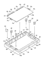
図1は、本発明の第1実施形態に係る梱包材で、第1の被梱包物を梱包する状態を示した模式的斜視図であり、図2は、第1実施形態に係る梱包材の側辺保護部材の模式的斜視図である。
[First Embodiment]
FIG. 1 is a schematic perspective view showing a state in which a first article to be packed is packed in the packaging material according to the first embodiment of the present invention, and FIG. 2 is a diagram of the packaging material according to the first embodiment. It is a typical perspective view of a side protection member.
図3は、(a)は、側部保護部材を容器本体に嵌合した状態の部分的上面図、(b)は、(a)のA−A断面図であり、図4は、(a)〜(c)は、幅の異なる第2〜第4の被梱包物を梱包した状態の部分的上面図である。図5は、図3(b)に相当する第1実施形態の変形例を示した模式的断面図である。 3A is a partial top view of a state in which the side protection member is fitted to the container body, FIG. 3B is a cross-sectional view taken along line AA of FIG. 4A, and FIG. (C) is a partial top view of a state in which second to fourth objects to be packed having different widths are packed. FIG. 5 is a schematic cross-sectional view showing a modification of the first embodiment corresponding to FIG.
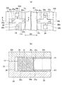
図1〜図5に示すように、梱包材1は、ガラスパネル等の複数枚の被梱包物を重ねて梱包するための梱包材である。具体的には、長辺方向の幅の異なるパネルからなる第1〜第4の被梱包物P1〜P4の4種類の被梱包物のいずれか1種を選択して、選択した1種の被梱包物を複数枚重ね合わせて、梱包するものである。なお、後述するように、第1〜第4の被梱包物(パネル)の長辺方向の幅W1〜W4は、この順に広くなっている(W1<W2<W3<W4)。
As shown in FIGS. 1 to 5, the packing
梱包材1は、蓋体10と容器本体20とを備えている。蓋体10および容器本体20の材質としては、熱可塑性樹脂の発泡成形体であることが好ましい。熱可塑性樹脂には、ポリスチレン系樹脂、ポリオレフィン系樹脂(例えばポリプロピレン系樹脂、ポリエチレン系樹脂)、ポリエステル系樹脂(例えば、ポリエチレンテレフタレート、ポリブチレンテレフタレート、ポリエチレンナフタレート、またはポリ乳酸)、またはポリカーボネート系樹脂などが挙げられ、単一の樹脂や複数の樹脂を複合したものを使用できる。被梱包物がガラスパネルや電子部品である場合には、帯電防止処理された原料が好ましく、例えば積水化成品工業(株)製のEPS(エスレン(登録商標)ビーズNSELM)、ピオセラン(登録商標)Lシリーズ(LP−30ENTR等)、Oシリーズ(OP−15ENS)、Sシリーズ(SP−40DNT)などを挙げることができる。
The packing
図1に示すように、蓋体10は、短辺方向および長辺方向の寸法が、容器本体20の寸法と一致しており、蓋体10には、その短辺方向および厚さ方向に沿って、複数のバンド溝18,18,…が形成されている。蓋体10の裏面側の外周縁11は、凸条となるように裏面から突出しており、後述する収納凹部21の開口端部(開口部)22aの外側に形成された外縁溝22bに、嵌合するようになっている。このようにして、容器本体20の収納凹部21に形成された開口端部22aを密閉するよう、蓋体10で容器本体20を覆うことができる。
As shown in FIG. 1, the
容器本体20は、底部23と、底部23の周りから立ち上がった側壁部24と、を有しており、容器本体20の中央には、底部23および側壁部24により、被梱包物を収納するための収納凹部21が形成されている。底部23の外面(底面)と、側壁部24の外側面とには、梱包時に蓋体10のバンド溝18と連続するように、バンド溝28,28,・・・が形成されている。
The
本実施形態では、梱包材1は、容器本体20に着脱自在に嵌合すると共に、第1〜第4の被梱包物P1〜P4のうち選択された被梱包物の両側の側辺部Psを保護する4つの側辺保護部材30をさらに備えている。各側辺保護部材30を構成する材料は、第1〜第4の被梱包物P1〜P4を保護することができるのであれば特に限定されるものではなく、例えば上述した蓋体10または容器本体20を構成する材料のうちいずれかの材料であってもよく、たとえば後述する衝撃緩衝材42において例示した材料であってもよい。
In the present embodiment, the packing
具体的には、側辺保護部材30には、側辺保護部材30が十字状となるように軸部31から放射状に延在するとともに、第1〜第4の梱包物P1〜P4に応じた長さL1〜L4を有した4つの第1〜第4の側辺部保護用アーム部32a〜32dが形成されている。
Specifically, the
すなわち、上述したように、第1〜第4の被梱包物(パネル)P1〜P4の幅W1〜W4は、この順に広くなっている(W1<W2<W3<W4)ことから、第1〜第4の側辺部保護用アーム部32a〜32dの長さL1〜L4は、この順に短くなっている(L1>L2>L3>L4)。
That is, as described above, the widths W1 to W4 of the first to fourth packages (panels) P1 to P4 are increased in this order (W1 <W2 <W3 <W4). The lengths L1 to L4 of the fourth side
さらに、図1および図3(a),(b)に示すように、容器本体20には、選択された被梱包物に応じた側辺部保護用アーム部(図では、第1の被梱包物P1に応じた第1の側辺部保護用アーム部32a)の先端面33aが、収納凹部21の内側壁面21fから露出して、被梱包物P1の側辺部を保護するように、側辺保護部材30に嵌合する嵌合凹部26が形成されている。
Further, as shown in FIG. 1 and FIGS. 3A and 3B, the
具体的には、嵌合凹部26は、十字状をした凹部であり、中央凹部26aから延在する各第1〜第4の側辺部保護用アーム部32a〜32dに嵌合する各アーム嵌合凹部26bは、最も長さの長い第1の側辺部保護用アーム部32aに合わせた形状となっている。これにより、第1〜第4の側辺部保護用アーム部32a〜32dのいずれかの先端面33a〜33dを収納凹部21の内側壁面21fから露出しするように、側辺保護部材30を嵌合凹部26に嵌合させることができる。
Specifically, the
さらに、第1〜第4の側辺部保護用アーム部31a〜31dの上面および下面には、選択される被梱包物に応じた側辺部保護用アーム部を認識するための認識部を有し、本実施形態の場合には文字が付されている。例えば、第1の側辺部保護用アーム部30aは、第1の被梱包物P1の側辺部Psを保護することから、その上面および下面には、「1」の文字が付されている。同様に、第2〜第4の側辺部保護用アーム部30b〜30dは、第2〜第4の被梱包物P2〜4の側辺部Psを保護することから、その上面および下面には、それぞれ「2」,「3」,「4」の文字が付されている。 In addition, the upper and lower surfaces of the first to fourth side edge protecting arm portions 31a to 31d have a recognition portion for recognizing the side edge protecting arm portion corresponding to the selected article to be packed. In the case of this embodiment, characters are added. For example, since the first side portion protection arm portion 30a protects the side portion Ps of the first article to be packed P1, the upper surface and the lower surface are marked with a character “1”. . Similarly, the second to fourth side edge protecting arms 30b to 30d protect the side edges Ps of the second to fourth packed objects P2 to P4, so , Characters “2”, “3”, and “4” are respectively attached.
なお、ここでは、認識部の一例として文字として数字が付されているが、例えば記号、色、形状などであってもよい。これらの認識部は、側辺保護部材30を成形する際に、上面および下面に凹凸により側辺保護部材30と一体的に付してもよく、成形後に記載または記載したフィルムまたはシートを上面および下面に貼着してもよい。
Here, numbers are attached as characters as an example of the recognition unit, but may be, for example, symbols, colors, shapes, and the like. When the
このようにして、梱包すべき被梱包物として、第1〜第4の被梱包物P1〜P4のうち第1の被梱包物P1を選択した場合には、図3(a),(b)に示すように、第1の被梱包物P1に応じた第1の側辺部保護用アーム部32aの先端面33aが、収納凹部21の内側壁面21fから露出するように、側辺保護部材30を嵌合凹部26に嵌合させる。
In this way, when the first packaged item P1 is selected from the first to fourth packaged items P1 to P4 as the packaged items to be packed, FIGS. 3 (a) and 3 (b). As shown in FIG. 4, the
そして、梱包すべき被梱包物として、第1〜第4の被梱包物P1〜P4のうち第2の被梱包物P2を選択した場合には、図4(a)に示すように、左右の側辺保護部材30を図3(a)の位置に対して90°反時計回りに回転させて、側辺保護部材30を嵌合凹部26に嵌合させる。これにより、第2の被梱包物P2に応じた第2の側辺部保護用アーム部32bの先端面33bを、収納凹部21の内側壁面21fから露出させることができる。
And when the 2nd to-be-packaged object P2 is selected among the 1st to 4th to-be-packaged objects P1 to P4 as the to-be-packaged objects to be packed, as shown in FIG. The
また、同様に、図4(b)に示すように、第3の被梱包物P3を選択した場合には、さらに90°反時計回りに回転させて、側辺保護部材30を嵌合凹部26に嵌合させる。これにより、第3の被梱包物P3に応じた第3の側辺部保護用アーム部32cの先端面33cを、収納凹部21の内側壁面21fから露出させることができる。さらに、図4(c)に示すように、第4の被梱包物P4を選択した場合には、さらに90°反時計回りに回転させて、側辺保護部材30を嵌合凹部26に嵌合させ、第4の被梱包物P4に応じた第4の側辺部保護用アーム部32dの先端面33dを、収納凹部21の内側壁面21fから露出させることができる。
Similarly, as shown in FIG. 4B, when the third article to be packed P3 is selected, the
このようにして、長辺方向の幅が異なる第1〜第4の被梱包物P1〜P4に合わせて側辺部保護用アーム部31a〜31dを選択することにより、いずれの被梱包物を梱包する場合であっても、その短辺方向の両側の側辺部Psに対向するように、側辺保護部材30を用いて、その側辺部保護用アーム部の先端面を配置することができる。
In this way, by packing the side portion protection arm portions 31a to 31d according to the first to fourth items to be packed P1 to P4 having different widths in the long side direction, any items to be packed can be packed. Even in this case, the side
この際に、第1〜第4の被梱包物P1〜P4のいずれかの被梱包物を選択するのに合わせて、側辺保護部材30の各側辺部保護用アーム部31a〜31dに付された数字を確認しながら、適切な側辺部保護用アーム部の先端面が内側壁面から露出するように、側辺保護部材30を嵌合凹部26に嵌合させることができる。
At this time, it is attached to each of the side portion protection arm portions 31a to 31d of the side
この結果、梱包体に衝撃または振動が作用した場合であっても、側辺部保護用アーム部の先端面で選択された被梱包物の側辺部を押さえ、選択された被梱包物を保護することができる。 As a result, even if an impact or vibration is applied to the package, the side of the selected package is pressed by the tip of the side protection arm to protect the selected package. can do.
ここで、図5に示す変形例の如く、側辺保護部材30を、容器本体20の開口端部22aから突出するようにすれば、容器本体20の開口端部22aの近傍まで、例えば第1の被梱包物P1を積み重ねて、収納凹部21に収納した場合であっても、側辺保護部材30により、最上段に積み重ねられた第1の被梱包物P1(図5の一点鎖線参照)が、側辺保護部材30を乗り越えることを抑制することができる。これにより、第1の被梱包物P1が、梱包材1から飛び出すことを防止することができる。
Here, as in the modification shown in FIG. 5, if the
〔第2実施形態〕
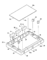
図6は、第2実施形態に係る梱包材の容器本体で、回路基板付き被梱包物を収納する状態を示した模式的斜視図である。図7は、(a)は、第2実施形態に係る梱包材の角部保護部材の模式的斜視図であり、(b)はその変形例を示した模式的斜視図である。
[Second Embodiment]
FIG. 6 is a schematic perspective view illustrating a state in which a packaged body with a circuit board is stored in the container body of the packaging material according to the second embodiment. FIG. 7A is a schematic perspective view of a corner protecting member of a packaging material according to the second embodiment, and FIG. 7B is a schematic perspective view showing a modification thereof.
図8は、図7(a)に示す角部保護部材を容器本体に嵌合した状態の部分的上面図である。図9は、(a)は、図8のB−B線矢視断面図であり、(b)は、図8のC−C線矢視断面図、(c)は、(a)に相当する第2実施形態の変形例を示した模式的断面図である。 FIG. 8 is a partial top view showing a state in which the corner portion protection member shown in FIG. 9A is a cross-sectional view taken along line B-B in FIG. 8, FIG. 9B is a cross-sectional view taken along line C-C in FIG. 8, and FIG. 9C corresponds to FIG. It is typical sectional drawing which showed the modification of 2nd Embodiment to do.
第2実施形態に係る梱包材が第1実施形態のものと相違する点は、回路基板付きの被梱包物を梱包するために角部保護部材さらに設けた点である。したがって、第1実施形態と同じ構成には、同じ符号を付して、詳細な説明を省略する。 The point that the packaging material according to the second embodiment is different from that of the first embodiment is that a corner portion protection member is further provided in order to package an article to be packed with a circuit board. Accordingly, the same components as those in the first embodiment are denoted by the same reference numerals, and detailed description thereof is omitted.
第2実施形態に係る梱包材は、図6に示すように、矩形状のパネルPaの3つの側辺部Psに、フレキシブル回路(フィルム回路)Pfを介して回路基板Pbが接続された第1の被梱包物(回路基板付き被梱包物)PAと、上述した、パネルからなる被梱包物(回路基板なし被梱包物)PNの2種類の被梱包物のいずれか1種を選択して、選択した1種の被梱包物を複数枚重ね合わせて、梱包するものである。さらに、回路基板付き被梱包物PAおよび回路基板なし被梱包物PNの各々は、上述したようにパネルの幅が異なった4種類のものがある。 As shown in FIG. 6, the packaging material according to the second embodiment is a first in which a circuit board Pb is connected to three side portions Ps of a rectangular panel Pa via a flexible circuit (film circuit) Pf. Select one of the two types of packaged items (packaged product with circuit board) PA and the above-mentioned packaged product (packaged product without circuit board) PN, A plurality of selected one type of objects to be packed are overlapped and packed. Further, each of the article to be packed PA with a circuit board and the article to be packed PN without a circuit board has four types having different panel widths as described above.
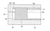
本実施形態に係る容器本体20の収納凹部21の底面21aの側縁部21bには、側縁部21bに沿って底面21aに配置された回路基板付き被梱包物PAの回路基板Pbを収容するための基板収容凹部21cが形成されている。これにより、回路基板付き被梱包物PAを複数枚積み重ねた際に、上下方向に扇状に膨らむ回路基板Pb,Pb…を、開口端部22aからはみ出さないように基板収容凹部21c内に逃がすことができる。
In the
さらに、収納凹部21の基板収容凹部21cが形成された側の隅部21d,21dには、隅部凹部21e,21eが形成されている。これにより、後述する角部保護部材40を、容器本体20の隅部凹部21eに着脱自在に嵌合することができる。
Further, corner recesses 21e and 21e are formed at the
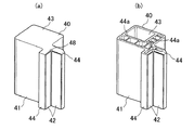
角部保護部材40,40は、回路基板付き被梱包物PAを梱包する際に、回路基板Pbが接続された側のパネルPaの一対の角部Pcを保護する部材である。具体的には、各角部保護部材40は、角部保護部材本体41および衝撃緩衝材42とからなる(図7(a),図8参照)。
The
角部保護部材本体41には、容器本体20の隅部凹部21eに嵌合する嵌合部43と、嵌合部43が嵌合した状態で収納凹部21の隅部21dから各内側壁面21fに沿って延在するように、嵌合部43に一体的に成形された一対の角部保護用アーム部44,44と、が形成されている。さらに、回路基板付き被梱包物PAの角部Pcから角部保護用アーム部44に作用する衝撃力により、角部保護用アーム部44,44同士の基端部に応力集中しないように、角部保護用アーム部44,44同士の基端部は、R形状の曲面48で連続している。さらに、衝撃緩衝材42は、パネルPaの角部Pcを保護するように各角部保護用アーム部44,44の表面に配置されている。
The corner protection member
ここで、図7(a)に示すように、嵌合部43および一対の角部保護用アーム部44,44は、中実構造であってもよいが、例えば、図7(b)に示すように、嵌合部43および一対の角部保護用アーム部44,44は、上下に開口が形成された中空構造であってもよく、さらには、内壁同士を接続するように形成された複数の補強リブ44a,44a,…を設けてもよい。
Here, as shown in FIG. 7A, the
また、角部保護部材本体41は、容器本体20および蓋体10よりも硬質の材料からなる。たとえば、角部保護部材本体41を構成する材料の縦弾性率は、容器本体20および蓋体10を構成する材料の縦弾性率よりも高いものが選定されている。容器本体20および蓋体10が上述した発泡樹脂材の場合、角部保護部材本体41は非発泡樹脂材が選定され、角部保護部材本体41の材料としては、ポリスチレン系樹脂、ポリオレフィン系樹脂、アクリル系樹脂、ポリカーボネートなどを挙げることができる。
Further, the corner protection member
このように、角部保護部材本体41は、容器本体20および蓋体10に比べて硬質となっており、回路基板付き被梱包物PAが梱包された梱包体に衝撃または振動が作用した際に、荷重が集中し易い収納凹部21の隅部には、角部保護部材40が配置されているので、容器本体20の破損または欠損を抑制することができる。
As described above, the corner protection member
さらに、衝撃緩衝材42は、回路基板付き被梱包物PAの角部Pcからの衝撃を吸収するシート材であり、角部保護部材本体41よりも軟質の、天然ゴム、イソプレンゴム、ブタジエンゴム、ウレタンゴム、スチレンブタジェンゴム、ニトリルゴム、ブチルゴム、エチレンプロピレンゴム、フッ素ゴム、アクリルゴムなどの材料、さらにはこれらを発泡させたもの、複数積層させたものであってもよい。
Further, the
このような梱包材1を用いて、回路基板付き被梱包物PAを梱包する際には、図8および図9(a)に示すように、容器本体20の隅部凹部21eに、角部保護部材40,40を嵌合させる。次に、基板収容凹部21cに回路基板付き被梱包物PAの回路基板Pbを逃がすように、回路基板付き被梱包物PAを収納凹部21内において合紙を挟んで積み重ねる。
When packing the article to be packed PA with a circuit board using such a
被梱包物PAを収納した容器本体20を蓋体10で覆い、容器本体20の開口端部22aを密閉するよう、蓋体10の裏面側の外周縁11を、容器本体20の外縁溝22bに嵌合させる。この嵌合状態で、バンド溝18,28に沿って3本のPPバンドなどの樹脂製バンド(図示せず)で、蓋体10および容器本体20を縛ることにより、梱包体とされる。
The
この際に、図9(a),図9(b)に示すように、収納凹部21の基板収容凹部21cが形成された側の一対の隅部21d,21dには、回路基板付き被梱包物PAのパネルPaの角部Pcを保護する一対の角部保護部材40,40が配置されている。これにより、振動または衝撃時には、フレキシブル回路Pfを介して回路基板Pbが接続された側辺部Ps側の角部Pcを、角部保護部材40により押さえて、第1の被梱包物P1の他の側辺部を、収納凹部21の内壁面によって押さえることができる。
At this time, as shown in FIGS. 9A and 9B, a pair of
特に、角部保護部材40の嵌合部43から延在する一対の角部保護用アーム部44,44の表面には、衝撃緩衝材42が貼着されているので、回路基板付き被梱包物PAの角部Pcから各側辺部Psに沿った部分を、衝撃緩衝材42により保護することができるとともに、梱包および開梱時において、角部保護部材40により回路基板付き被梱包物PAの角部Pcが接触することによる容器本体20の破損を防止することができる。
In particular, since the shock-absorbing
さらに、嵌合部43が嵌合した状態で、角部保護部材40に衝撃が作用した際には、角部保護用アーム部44に回路基板付き被梱包物PAの角部Pcが接触し、角部保護用アーム部44が撓む。この結果、角部保護用アーム部44により回路基板付き被梱包物PAの角部Pcの衝撃を緩衝することができる。
Furthermore, when an impact is applied to the
ここで、図9(c)に示す変形例の如く、角部保護部材40の角部保護用アーム部44を、容器本体20の開口端部22aから突出してもよい。このようにすれば、容器本体20の開口端部22aの近傍まで、回路基板付き被梱包物PAを積み重ねて、収納凹部21に収納した場合であっても、角部保護用アーム部44により、最上段に積み重ねられた回路基板付き被梱包物PA(図9(c)の一点鎖線参照)の角部Pcが、角部保護用アーム部44を乗り越えることを抑制することができる。これにより、回路基板付き被梱包物PAが、梱包材1から飛び出すことを防止することができる。
Here, as in the modification shown in FIG. 9C, the corner portion
さらに、回路基板なし被梱包物を梱包する際には、一対の角部保護部材40,40を容器本体20から取り外した状態で、容器本体20の収納凹部21内に、回路基板なし被梱包物を積み重ねて収納すればよい。回路基板なし被梱包物の大きさは、回路基板付き被梱包物PAのパネルよりも短辺方向が長く、開口端部22aの大きさに略等しいので、収納された第2の被梱包物PNは、収納凹部21の内側壁面21fで保護されることになる。回路基板付き被梱包物PAおよび回路基板なし被梱包物の長辺方向の幅が異なるものを選択した場合には、第1実施形態に示したように、側辺保護部材30の向きを適切な向きに向けて、側辺保護部材30を嵌合凹部26に嵌合させて、側辺部保護用アーム部で、選択された被梱包物の側辺部を保護すればよい。
Further, when packing an object to be packed without a circuit board, the object without a circuit board is placed in the
このようにして、パネルの長辺方向の幅が異なる被梱包物ばかりでなく、さらには、パネルの側辺部Psにフレキシブル回路Pfを介して回路基板Pbが接続された回路基板付き被梱包物PAおよびパネルのみからなる回路基板なし被梱包物のいずれの種類の被梱包物を選択した場合であっても、共通の容器本体20および蓋体10を兼用して、これらを梱包することができる。
In this way, not only a packaged object having a different width in the long side direction of the panel, but also a packaged object with a circuit board in which the circuit board Pb is connected to the side part Ps of the panel via the flexible circuit Pf. Even if any type of packaged object without a circuit board consisting of only PA and a panel is selected, these can be packaged using the
〔第3実施形態〕
図10は、本発明の第3実施形態に係る梱包材を説明するための模式的斜視図であり、(a)は、蓋体裏面側の模式的斜視図、(b)は、容器本体の模式的斜視図である。
[Third Embodiment]
FIG. 10 is a schematic perspective view for explaining the packing material according to the third embodiment of the present invention, (a) is a schematic perspective view of the back side of the lid, and (b) is a view of the container body. It is a typical perspective view.
第3実施形態に係る梱包材が第2実施形態のものと相違する点は、一対の角部保護部材および側辺保護部材を蓋体に嵌合させた点である。したがって、第1実施形態と同じ構成には、同じ符号を付して、詳細な説明を省略する。 The difference between the packaging material according to the third embodiment and that of the second embodiment is that a pair of corner portion protection members and side protection members are fitted to the lid. Accordingly, the same components as those in the first embodiment are denoted by the same reference numerals, and detailed description thereof is omitted.
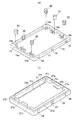
図10(a)に示すように、本実施形態では、蓋体10の短辺方向に沿った縁部には、側辺保護部材30が嵌合するように、嵌合凹部14aが形成されている。また、蓋体10の裏面側の隅部13には、角部保護部材40の嵌合部43が着脱自在に嵌合するように、嵌合凹部14bが形成されている。
As shown in FIG. 10A, in this embodiment, a
容器本体20には、蓋体10を容器本体20に被着したときに、蓋体10の嵌合凹部14aに嵌合した状態の各側辺保護部材30の側辺部保護用アーム部31の先端面32が、収納凹部21の内側壁面21fから露出するように、側部凹部27aが形成されている。
When the
同様に、蓋体10を容器本体20に被着したときに、蓋体10の嵌合凹部14に嵌合した状態の角部保護部材40を収納するとともに、一対の角部保護用アーム部44,44のそれぞれが、収納凹部21の隅部21dから各内側壁面21fに沿って延在するように、容器本体20の隅部21d,21dには隅部凹部27bが形成されている。
Similarly, when the
このように構成することにより、共通の蓋体10および容器本体20を兼用して、パネルの長辺方向の幅が異なる被梱包物ばかりでなく、回路基板付き被梱包物およびパネルのみからなる回路基板なし被梱包物をも梱包することができるとともに、側辺保護部材30および角部保護部材40が蓋体10に嵌合しているので、梱包体に衝撃または振動が作用したとしても、最上段の被梱包物Pが容器本体20の開口端部22aを乗り越えることを抑制することができる。
By constituting in this way, the circuit which consists only of the to-be-packaged object with a circuit board and a panel using not only the to-be-packaged object from which the width | variety of the long side direction of a panel differs using the
〔第4実施形態〕
図11は、本発明の第4実施形態に係る梱包材で回路基板付きの被梱包物を梱包する状態を説明するための模式的斜視図である。図12は、回路基板なし被梱包物を図11に示す容器本体に収納する状態を示した模式的斜視図である。
[Fourth Embodiment]
FIG. 11: is a typical perspective view for demonstrating the state which packs the to-be-packaged object with a circuit board with the packing material which concerns on 4th Embodiment of this invention. 12 is a schematic perspective view showing a state in which an object to be packed without a circuit board is stored in the container body shown in FIG.
第4実施形態に係る梱包材が第2実施形態のものと相違する点は、容器本体の収納凹部の内側壁面に嵌合する側辺緩衝部材を設けた点である。したがって、第2実施形態と同じ構成は、同じ符号を付して、詳細な説明を一部省略する。 The difference between the packaging material according to the fourth embodiment and that of the second embodiment is that a side buffer member that fits into the inner wall surface of the storage recess of the container body is provided. Accordingly, the same components as those of the second embodiment are denoted by the same reference numerals, and detailed description thereof is partially omitted.
図11および図12に示すように、容器本体20の収納凹部21の内側壁面21fには、開口端部22aから底面21aに向かって、複数の嵌合溝29が形成されている。この嵌合溝29は、側辺緩衝部材50と容器本体20とを嵌合するための溝である。
As shown in FIGS. 11 and 12, a plurality of
図12に示すように、側辺緩衝部材50は、図12に示す大きさの回路基板なし被梱包物PNの1つ側辺部Psを押さえることができる程度の肉厚となっており、隣接する2つの嵌合溝29,29に着脱自在に嵌合するように、一対の嵌合凸条51が形成されている。側辺緩衝部材50は、上述した蓋体10または容器本体20を構成する材料と同じ材料であってもよく、衝撃緩衝材42を構成する材料と同じであってもよい。
As shown in FIG. 12, the
第2実施形態に示したのと同様に(図6参照)、収納凹部21の隅部21dに形成された隅部凹部21eに、各角部保護部材40を嵌合させた状態で、回路基板付き被梱包物PAを収納凹部21内において積み重ねて、これらを梱包することができる。
In the same manner as shown in the second embodiment (see FIG. 6), in a state where each
さらに、第2実施形態の第2の被梱包物よりも短辺方向の幅が短い回路基板なし被梱包物PNを梱包する際には、図12に示すように、収納凹部21の内側壁面21fの嵌合溝29に、側辺緩衝部材50の嵌合凸条51を嵌合させることにより、回路基板なし被梱包物PNの大きさに応じた収納空間が形成される。この結果、側辺緩衝部材50が、収納凹部21に収納された第2の被梱包物PNの側辺部Psに沿って配置されることになるので、側辺部Psを側辺緩衝部材50で保護することができる。
Furthermore, when packing the circuit board-less packaged object PN having a shorter width in the short side direction than the second packaged object of the second embodiment, as shown in FIG. By fitting the
以上、本発明の実施の形態を用いて詳述してきたが、具体的な構成はこの実施形態及び実施例に限定されるものではなく、本発明の要旨を逸脱しない範囲における設計変更があっても、それらは本発明に含まれるものである。 As mentioned above, although it explained in full detail using embodiment of this invention, a concrete structure is not limited to this embodiment and an Example, There exists a design change in the range which does not deviate from the summary of this invention. They are also included in the present invention.
本実施形態では、角部保護部材は、容器本体または蓋体のいずれか一方に嵌合するようになっていたが、角部保護部材を着脱自在に嵌合することができるのであれば、角部保護部材は、容器本体および蓋体の双方に嵌合するようになっていてもよい。 In this embodiment, the corner protection member is adapted to be fitted to either the container body or the lid, but if the corner protection member can be detachably fitted, The part protection member may be fitted to both the container body and the lid.
さらに、容器本体の隅部凹部とは異なる位置(例えば容器本体の上面)に、角部保護部材を収納する収納部が形成されていてもよい。これにより、回路基板付き被梱包物を収納する際には角部保護部材は使用しないので収納部に収納することができる。また、回路基板付き被梱包物を収納する際には、角部保護部材を収納部から取り出して使用することができる。このようにいずれの被梱包物の梱包にかかわらず、角部保護部材を容器本体とともに一体的に搬送することができる。 Further, a storage portion for storing the corner protection member may be formed at a position different from the corner recess of the container body (for example, the upper surface of the container body). Thereby, when storing the packaged article with a circuit board, since a corner | angular part protection member is not used, it can be stored in a storage part. Moreover, when accommodating the to-be-packaged goods with a circuit board, a corner | angular part protection member can be taken out from a storage part and can be used. In this way, the corner portion protection member can be integrally transported together with the container body regardless of the packaging of any items to be packed.
1:梱包材、10:蓋体、11:外周縁、13:隅部、14a,14b:嵌合凹部、18:バンド溝、20:容器本体、21:収納凹部、21a:底面、21b:側縁部、21c:基板収容凹部、21d:隅部、21e:隅部凹部、21f:内側壁面、22a:開口端部、22b:外縁溝、23:底部、24:側壁部、27a:側部凹部、27b:隅部凹部、26:嵌合凹部、26a:中央凹部、26b:アーム嵌合凹部、28:バンド溝、30:側辺保護部材、31:軸部、32a〜32d:第1〜第4の側辺部保護用アーム部、33a〜33d:先端面、29:嵌合溝、40:角部保護部材、41:角部保護部材本体、42:衝撃緩衝材、43:嵌合部、44:角部保護用アーム部、44a:補強リブ、48:曲面、50:側辺緩衝部材、51嵌合凸条、P1〜P4:第1〜第4の被梱包物、PA:回路基板付き被梱包物,PN:回路基板なし被梱包物、Pa:パネル、Pb:回路基板、Pc:角部、Pf:フレキシブル回路、Ps:側辺部 1: packing material, 10: lid, 11: outer periphery, 13: corner, 14a, 14b: fitting recess, 18: band groove, 20: container body, 21: storage recess, 21a: bottom surface, 21b: side Edge, 21c: Substrate housing recess, 21d: Corner, 21e: Corner recess, 21f: Inner wall surface, 22a: Open end, 22b: Outer edge groove, 23: Bottom, 24: Side wall, 27a: Side recess 27b: corner recess, 26: fitting recess, 26a: central recess, 26b: arm fitting recess, 28: band groove, 30: side protection member, 31: shaft portion, 32a to 32d: first to first 4 side side protection arm portions, 33a to 33d: tip surface, 29: fitting groove, 40: corner portion protection member, 41: corner portion protection member main body, 42: shock absorbing material, 43: fitting portion, 44: Arm portion for corner protection, 44a: Reinforcing rib, 48: Curved surface, 50: Side buffer member 51 fitting ridges, P1 to P4: first to fourth packaged objects, PA: packaged object with circuit board, PN: packaged object without circuit board, Pa: panel, Pb: circuit board, Pc: square Part, Pf: flexible circuit, Ps: side part
Claims (10)
前記梱包材は、前記被梱包物を収納する収納凹部が形成された容器本体と、前記収納凹部に形成された開口端部を密閉するように前記容器本体を覆う蓋体と、前記容器本体または前記蓋体の少なくともいずれか一方に着脱自在に嵌合すると共に、前記選択された被梱包物の両側の側辺部を保護する側辺保護部材と、を備えており、
前記各側辺保護部材には、軸部から放射状に延在するとともに、前記複数種の被梱包物に応じた長さを有した複数の側辺部保護用アーム部が形成されており、
前記容器本体または蓋体には、選択された被梱包物に応じた前記側辺部保護用アーム部の先端面が、前記収納凹部の内側壁面から露出して前記側辺部を保護するように、前記側辺保護部材に嵌合する嵌合凹部が形成されていることを特徴とする梱包材。 It is a packing material for selecting and packing one type from a plurality of types of panel-shaped packed items having different widths,
The packaging material includes a container main body in which a storage concave portion that stores the packaged object is formed, a lid that covers the container main body so as to seal an opening end formed in the storage concave portion, and the container main body or A side protection member that detachably fits to at least one of the lids and protects the side parts on both sides of the selected packaged item, and
Each side protection member has a plurality of side protection arms that extend radially from the shaft and have a length corresponding to the plurality of types of items to be packed.
The container body or the lid is configured such that a front end surface of the side side protection arm portion corresponding to the selected article to be packed is exposed from the inner wall surface of the storage recess to protect the side side portion. The packing material characterized by the above-mentioned. The fitting recessed part fitted to the said side protection member is formed.
前記収納凹部の底面の側縁部には、前記回路基板を収容するための基板収容凹部が形成されており、
前記収納凹部の前記基板収容凹部が形成された側の隅部には、前記容器本体または前記蓋体の少なくともいずれか一方に着脱自在に嵌合すると共に、前記被梱包物のパネルの角部を保護する角部保護部材が設けられていることを特徴とする請求項1〜4のいずれかに記載の梱包材。 The plurality of types of objects to be packaged include a packaged object in which a circuit board is connected to a side portion of a rectangular panel via a flexible circuit,
On the side edge portion of the bottom surface of the storage recess, a substrate storage recess for storing the circuit board is formed,
The corner of the housing recess on the side where the substrate housing recess is formed is detachably fitted to at least one of the container body and the lid, and the corner of the panel of the packaged object is The packaging material according to any one of claims 1 to 4, wherein a corner protection member for protection is provided.
前記パネルを保護するように前記各角部保護用アーム部の表面に配置された衝撃緩衝材と、を備えていることを特徴とする請求項5に記載の梱包材。 The corner protection member extends along each inner wall from a fitting portion that fits into the container body or the lid, and a corner portion of the storage recess when the fitting portion is fitted. A pair of corner protection arm portions connected to the fitting portion, and a protection member main body formed,
The packing material according to claim 5, further comprising an impact cushioning material disposed on a surface of each of the corner protection arm portions so as to protect the panel.
Priority Applications (4)
| Application Number | Priority Date | Filing Date | Title |
|---|---|---|---|
| JP2012147855A JP5917316B2 (en) | 2012-06-29 | 2012-06-29 | Packing material and package |
| TW102122995A TWI492890B (en) | 2012-06-29 | 2013-06-27 | Packaging materials and packaging |
| KR1020130074423A KR101461011B1 (en) | 2012-06-29 | 2013-06-27 | Packaging material and package |
| CN201310269174.3A CN103523336B (en) | 2012-06-29 | 2013-06-28 | Packing timber and packaging body |
Applications Claiming Priority (1)
| Application Number | Priority Date | Filing Date | Title |
|---|---|---|---|
| JP2012147855A JP5917316B2 (en) | 2012-06-29 | 2012-06-29 | Packing material and package |
Publications (2)
| Publication Number | Publication Date |
|---|---|
| JP2014009019A true JP2014009019A (en) | 2014-01-20 |
| JP5917316B2 JP5917316B2 (en) | 2016-05-11 |
Family
ID=49925779
Family Applications (1)
| Application Number | Title | Priority Date | Filing Date |
|---|---|---|---|
| JP2012147855A Active JP5917316B2 (en) | 2012-06-29 | 2012-06-29 | Packing material and package |
Country Status (4)
| Country | Link |
|---|---|
| JP (1) | JP5917316B2 (en) |
| KR (1) | KR101461011B1 (en) |
| CN (1) | CN103523336B (en) |
| TW (1) | TWI492890B (en) |
Families Citing this family (10)
| Publication number | Priority date | Publication date | Assignee | Title |
|---|---|---|---|---|
| CN103818657B (en) | 2014-01-27 | 2016-02-03 | 深圳市华星光电技术有限公司 | Liquid-crystalline glasses panel packing |
| CN104192444B (en) * | 2014-09-02 | 2016-06-08 | 深圳市华星光电技术有限公司 | Liquid crystal panel tr |
| CN105173333B (en) * | 2015-09-25 | 2017-04-05 | 武汉华星光电技术有限公司 | Glass substrate packing box |
| CN105217125B (en) * | 2015-11-05 | 2017-11-10 | 京东方科技集团股份有限公司 | A kind of packing case and its packing method |
| CN105600154B (en) * | 2016-02-15 | 2018-11-23 | 苏州合普橡塑有限公司 | Liquid-crystalline glasses screen packing box |
| CN105752456B (en) * | 2016-03-25 | 2018-06-05 | 京东方科技集团股份有限公司 | Packing case and packing method |
| CN105691914B (en) * | 2016-04-08 | 2018-01-30 | 深圳市华星光电技术有限公司 | Liquid crystal panel-packaging box |
| WO2018211667A1 (en) * | 2017-05-18 | 2018-11-22 | 堺ディスプレイプロダクト株式会社 | Container |
| CN111032534A (en) * | 2017-09-08 | 2020-04-17 | 堺显示器制品株式会社 | Container and protective member |
| CN112978087B (en) * | 2021-02-22 | 2022-07-12 | 惠州市华星光电技术有限公司 | Display panel package combination |
Citations (6)
| Publication number | Priority date | Publication date | Assignee | Title |
|---|---|---|---|---|
| US3049260A (en) * | 1960-07-13 | 1962-08-14 | Alton H Stone | Cushioning material |
| JPS6140366U (en) * | 1984-08-18 | 1986-03-14 | 旭化成株式会社 | Cushioning material for packaging |
| JP2005145461A (en) * | 2003-11-11 | 2005-06-09 | Sharp Corp | Storage tray |
| JP2005212815A (en) * | 2004-01-28 | 2005-08-11 | Orion Denki Kk | Packaging material and packed-up electric appliance |
| JP2008100740A (en) * | 2006-10-20 | 2008-05-01 | Matsushita Electric Ind Co Ltd | Enclosed stand buffering member |
| US20080128310A1 (en) * | 2006-12-01 | 2008-06-05 | Innolux Display Corp. | Packing case with buffers for holding multi-size substrates of display device |
Family Cites Families (12)
| Publication number | Priority date | Publication date | Assignee | Title |
|---|---|---|---|---|
| CH666460A5 (en) * | 1987-09-30 | 1988-07-29 | Hanspeter Zoller C O Ramel & Z | Versatile rigid foam packaging unit - has lid with edge grooves to hold on with clips and inspection holes and sides with shapes to lock contents in position |
| JP2533359Y2 (en) * | 1990-03-23 | 1997-04-23 | 東陶機器株式会社 | Wall panel for toilet booth |
| JPH1018441A (en) * | 1996-07-08 | 1998-01-20 | Nippon Light Metal Co Ltd | Connecting structure of panel |
| JP4601932B2 (en) * | 2003-09-16 | 2010-12-22 | 大日本印刷株式会社 | PCB storage case |
| DE202005011897U1 (en) * | 2005-07-26 | 2005-10-06 | Hasenkamp Internationale Transporte Gmbh | Transport box for picture frames and the like comprises a distance piece corresponding to the distance between the picture frame top element or a piece of cushioning material on this element and the box lid |
| JP4628220B2 (en) * | 2005-08-23 | 2011-02-09 | 積水化成品工業株式会社 | Plate container |
| JP4933840B2 (en) | 2006-05-29 | 2012-05-16 | 株式会社ジェイエスピー | Glass substrate transport box and glass substrate transport package |
| KR100812766B1 (en) | 2006-09-26 | 2008-03-12 | 김봉희 | A box for keeping glass substrate |
| CN200974674Y (en) * | 2006-10-25 | 2007-11-14 | 常宏保丽龙有限公司 | Packing box |
| TWM326523U (en) * | 2007-08-08 | 2008-02-01 | Ynidyi Entpr Co Ltd | Packaging box for LCD panel with enhanced buffering function |
| JP5227827B2 (en) * | 2009-02-16 | 2013-07-03 | 積水化成品工業株式会社 | Glass substrate container |
| CN202046598U (en) * | 2011-05-13 | 2011-11-23 | 京东方科技集团股份有限公司 | Multi-size compatible safety deposit box |
-
2012
- 2012-06-29 JP JP2012147855A patent/JP5917316B2/en active Active
-
2013
- 2013-06-27 TW TW102122995A patent/TWI492890B/en active
- 2013-06-27 KR KR1020130074423A patent/KR101461011B1/en active IP Right Grant
- 2013-06-28 CN CN201310269174.3A patent/CN103523336B/en active Active
Patent Citations (6)
| Publication number | Priority date | Publication date | Assignee | Title |
|---|---|---|---|---|
| US3049260A (en) * | 1960-07-13 | 1962-08-14 | Alton H Stone | Cushioning material |
| JPS6140366U (en) * | 1984-08-18 | 1986-03-14 | 旭化成株式会社 | Cushioning material for packaging |
| JP2005145461A (en) * | 2003-11-11 | 2005-06-09 | Sharp Corp | Storage tray |
| JP2005212815A (en) * | 2004-01-28 | 2005-08-11 | Orion Denki Kk | Packaging material and packed-up electric appliance |
| JP2008100740A (en) * | 2006-10-20 | 2008-05-01 | Matsushita Electric Ind Co Ltd | Enclosed stand buffering member |
| US20080128310A1 (en) * | 2006-12-01 | 2008-06-05 | Innolux Display Corp. | Packing case with buffers for holding multi-size substrates of display device |
Also Published As
| Publication number | Publication date |
|---|---|
| TW201408555A (en) | 2014-03-01 |
| JP5917316B2 (en) | 2016-05-11 |
| KR101461011B1 (en) | 2014-11-13 |
| CN103523336B (en) | 2016-01-27 |
| CN103523336A (en) | 2014-01-22 |
| KR20140002524A (en) | 2014-01-08 |
| TWI492890B (en) | 2015-07-21 |
Similar Documents
| Publication | Publication Date | Title |
|---|---|---|
| JP5917316B2 (en) | Packing material and package | |
| JP2014009020A (en) | Packaging material and packaging body | |
| US6840381B2 (en) | Packaging for fragile items | |
| JP2003063569A (en) | Packaging cushioning material and container equipped with the same | |
| JP6357218B2 (en) | Packing material and package | |
| JP3210846U (en) | Panel transport container | |
| KR101252519B1 (en) | Packing box | |
| JP3201500U (en) | Packing material and package | |
| WO2018199026A1 (en) | Packaging tray | |
| JP6587966B2 (en) | Packing material | |
| JP2002193341A (en) | Tray for casing thin product | |
| JP6673136B2 (en) | Packaging materials | |
| JP2792404B2 (en) | How to assemble the package | |
| KR101574610B1 (en) | cover for packing boxes | |
| KR101252522B1 (en) | Packing box | |
| JP4841258B2 (en) | Packing box having cushioning material for packing box and cushioning material for packing box | |
| JP5542455B2 (en) | Packing equipment | |
| CN115724045A (en) | Server packing box | |
| JP5629806B2 (en) | Packing material | |
| KR100442327B1 (en) | Packing structure for wall suspending fan | |
| JP3180302U (en) | Packing material | |
| JP2016155568A (en) | Packing member and packaging using the same | |
| JP2007131345A (en) | Packaging shock absorbing material | |
| KR20070064815A (en) | Pulp mold for packing an electronic appliance |
Legal Events
| Date | Code | Title | Description |
|---|---|---|---|
| A621 | Written request for application examination |
Free format text: JAPANESE INTERMEDIATE CODE: A621 Effective date: 20141110 |
|
| A977 | Report on retrieval |
Free format text: JAPANESE INTERMEDIATE CODE: A971007 Effective date: 20150728 |
|
| A131 | Notification of reasons for refusal |
Free format text: JAPANESE INTERMEDIATE CODE: A131 Effective date: 20150825 |
|
| A521 | Written amendment |
Free format text: JAPANESE INTERMEDIATE CODE: A523 Effective date: 20151008 |
|
| TRDD | Decision of grant or rejection written | ||
| A01 | Written decision to grant a patent or to grant a registration (utility model) |
Free format text: JAPANESE INTERMEDIATE CODE: A01 Effective date: 20160315 |
|
| A61 | First payment of annual fees (during grant procedure) |
Free format text: JAPANESE INTERMEDIATE CODE: A61 Effective date: 20160406 |
|
| R150 | Certificate of patent or registration of utility model |
Ref document number: 5917316 Country of ref document: JP Free format text: JAPANESE INTERMEDIATE CODE: R150 |