JP2014005156A - Ammonia purification system - Google Patents

Ammonia purification system Download PDF

Info

Publication number
JP2014005156A
JP2014005156A JP2012139879A JP2012139879A JP2014005156A JP 2014005156 A JP2014005156 A JP 2014005156A JP 2012139879 A JP2012139879 A JP 2012139879A JP 2012139879 A JP2012139879 A JP 2012139879A JP 2014005156 A JP2014005156 A JP 2014005156A
Authority
JP
Japan
Prior art keywords
ammonia
adsorption
adsorbent
adsorption tower
pipe
Prior art date
Legal status (The legal status is an assumption and is not a legal conclusion. Google has not performed a legal analysis and makes no representation as to the accuracy of the status listed.)
Pending
Application number
JP2012139879A
Other languages
Japanese (ja)
Inventor
Shinichi Tai
慎一 田井
Shigeru Morimoto
茂 森本
Shuji Tsuno
修司 津野
Current Assignee (The listed assignees may be inaccurate. Google has not performed a legal analysis and makes no representation or warranty as to the accuracy of the list.)
Sumitomo Seika Chemicals Co Ltd
Original Assignee
Sumitomo Seika Chemicals Co Ltd
Priority date (The priority date is an assumption and is not a legal conclusion. Google has not performed a legal analysis and makes no representation as to the accuracy of the date listed.)
Filing date
Publication date
Application filed by Sumitomo Seika Chemicals Co Ltd filed Critical Sumitomo Seika Chemicals Co Ltd
Priority to JP2012139879A priority Critical patent/JP2014005156A/en
Priority to KR1020137014966A priority patent/KR20140025317A/en
Priority to CN201280004087.9A priority patent/CN103635427A/en
Priority to PCT/JP2012/082960 priority patent/WO2013190731A1/en
Priority to TW101150685A priority patent/TW201400415A/en
Publication of JP2014005156A publication Critical patent/JP2014005156A/en
Pending legal-status Critical Current

Links

Images

Classifications

    • CCHEMISTRY; METALLURGY
    • C01INORGANIC CHEMISTRY
    • C01CAMMONIA; CYANOGEN; COMPOUNDS THEREOF
    • C01C1/00Ammonia; Compounds thereof
    • C01C1/02Preparation, purification or separation of ammonia
    • BPERFORMING OPERATIONS; TRANSPORTING
    • B01PHYSICAL OR CHEMICAL PROCESSES OR APPARATUS IN GENERAL
    • B01DSEPARATION
    • B01D53/00Separation of gases or vapours; Recovering vapours of volatile solvents from gases; Chemical or biological purification of waste gases, e.g. engine exhaust gases, smoke, fumes, flue gases, aerosols
    • B01D53/02Separation of gases or vapours; Recovering vapours of volatile solvents from gases; Chemical or biological purification of waste gases, e.g. engine exhaust gases, smoke, fumes, flue gases, aerosols by adsorption, e.g. preparative gas chromatography
    • B01D53/04Separation of gases or vapours; Recovering vapours of volatile solvents from gases; Chemical or biological purification of waste gases, e.g. engine exhaust gases, smoke, fumes, flue gases, aerosols by adsorption, e.g. preparative gas chromatography with stationary adsorbents
    • BPERFORMING OPERATIONS; TRANSPORTING
    • B01PHYSICAL OR CHEMICAL PROCESSES OR APPARATUS IN GENERAL
    • B01JCHEMICAL OR PHYSICAL PROCESSES, e.g. CATALYSIS OR COLLOID CHEMISTRY; THEIR RELEVANT APPARATUS
    • B01J20/00Solid sorbent compositions or filter aid compositions; Sorbents for chromatography; Processes for preparing, regenerating or reactivating thereof
    • B01J20/02Solid sorbent compositions or filter aid compositions; Sorbents for chromatography; Processes for preparing, regenerating or reactivating thereof comprising inorganic material
    • B01J20/06Solid sorbent compositions or filter aid compositions; Sorbents for chromatography; Processes for preparing, regenerating or reactivating thereof comprising inorganic material comprising oxides or hydroxides of metals not provided for in group B01J20/04
    • B01J20/08Solid sorbent compositions or filter aid compositions; Sorbents for chromatography; Processes for preparing, regenerating or reactivating thereof comprising inorganic material comprising oxides or hydroxides of metals not provided for in group B01J20/04 comprising aluminium oxide or hydroxide; comprising bauxite
    • BPERFORMING OPERATIONS; TRANSPORTING
    • B01PHYSICAL OR CHEMICAL PROCESSES OR APPARATUS IN GENERAL
    • B01JCHEMICAL OR PHYSICAL PROCESSES, e.g. CATALYSIS OR COLLOID CHEMISTRY; THEIR RELEVANT APPARATUS
    • B01J20/00Solid sorbent compositions or filter aid compositions; Sorbents for chromatography; Processes for preparing, regenerating or reactivating thereof
    • B01J20/02Solid sorbent compositions or filter aid compositions; Sorbents for chromatography; Processes for preparing, regenerating or reactivating thereof comprising inorganic material
    • B01J20/10Solid sorbent compositions or filter aid compositions; Sorbents for chromatography; Processes for preparing, regenerating or reactivating thereof comprising inorganic material comprising silica or silicate
    • B01J20/103Solid sorbent compositions or filter aid compositions; Sorbents for chromatography; Processes for preparing, regenerating or reactivating thereof comprising inorganic material comprising silica or silicate comprising silica
    • BPERFORMING OPERATIONS; TRANSPORTING
    • B01PHYSICAL OR CHEMICAL PROCESSES OR APPARATUS IN GENERAL
    • B01JCHEMICAL OR PHYSICAL PROCESSES, e.g. CATALYSIS OR COLLOID CHEMISTRY; THEIR RELEVANT APPARATUS
    • B01J20/00Solid sorbent compositions or filter aid compositions; Sorbents for chromatography; Processes for preparing, regenerating or reactivating thereof
    • B01J20/02Solid sorbent compositions or filter aid compositions; Sorbents for chromatography; Processes for preparing, regenerating or reactivating thereof comprising inorganic material
    • B01J20/10Solid sorbent compositions or filter aid compositions; Sorbents for chromatography; Processes for preparing, regenerating or reactivating thereof comprising inorganic material comprising silica or silicate
    • B01J20/16Alumino-silicates
    • B01J20/18Synthetic zeolitic molecular sieves
    • B01J20/186Chemical treatments in view of modifying the properties of the sieve, e.g. increasing the stability or the activity, also decreasing the activity
    • BPERFORMING OPERATIONS; TRANSPORTING
    • B01PHYSICAL OR CHEMICAL PROCESSES OR APPARATUS IN GENERAL
    • B01JCHEMICAL OR PHYSICAL PROCESSES, e.g. CATALYSIS OR COLLOID CHEMISTRY; THEIR RELEVANT APPARATUS
    • B01J20/00Solid sorbent compositions or filter aid compositions; Sorbents for chromatography; Processes for preparing, regenerating or reactivating thereof
    • B01J20/02Solid sorbent compositions or filter aid compositions; Sorbents for chromatography; Processes for preparing, regenerating or reactivating thereof comprising inorganic material
    • B01J20/20Solid sorbent compositions or filter aid compositions; Sorbents for chromatography; Processes for preparing, regenerating or reactivating thereof comprising inorganic material comprising free carbon; comprising carbon obtained by carbonising processes
    • BPERFORMING OPERATIONS; TRANSPORTING
    • B01PHYSICAL OR CHEMICAL PROCESSES OR APPARATUS IN GENERAL
    • B01JCHEMICAL OR PHYSICAL PROCESSES, e.g. CATALYSIS OR COLLOID CHEMISTRY; THEIR RELEVANT APPARATUS
    • B01J20/00Solid sorbent compositions or filter aid compositions; Sorbents for chromatography; Processes for preparing, regenerating or reactivating thereof
    • B01J20/28Solid sorbent compositions or filter aid compositions; Sorbents for chromatography; Processes for preparing, regenerating or reactivating thereof characterised by their form or physical properties
    • B01J20/28014Solid sorbent compositions or filter aid compositions; Sorbents for chromatography; Processes for preparing, regenerating or reactivating thereof characterised by their form or physical properties characterised by their form
    • B01J20/28052Several layers of identical or different sorbents stacked in a housing, e.g. in a column
    • BPERFORMING OPERATIONS; TRANSPORTING
    • B01PHYSICAL OR CHEMICAL PROCESSES OR APPARATUS IN GENERAL
    • B01JCHEMICAL OR PHYSICAL PROCESSES, e.g. CATALYSIS OR COLLOID CHEMISTRY; THEIR RELEVANT APPARATUS
    • B01J20/00Solid sorbent compositions or filter aid compositions; Sorbents for chromatography; Processes for preparing, regenerating or reactivating thereof
    • B01J20/281Sorbents specially adapted for preparative, analytical or investigative chromatography
    • B01J20/282Porous sorbents
    • B01J20/283Porous sorbents based on silica
    • BPERFORMING OPERATIONS; TRANSPORTING
    • B01PHYSICAL OR CHEMICAL PROCESSES OR APPARATUS IN GENERAL
    • B01JCHEMICAL OR PHYSICAL PROCESSES, e.g. CATALYSIS OR COLLOID CHEMISTRY; THEIR RELEVANT APPARATUS
    • B01J20/00Solid sorbent compositions or filter aid compositions; Sorbents for chromatography; Processes for preparing, regenerating or reactivating thereof
    • B01J20/30Processes for preparing, regenerating, or reactivating
    • B01J20/34Regenerating or reactivating
    • B01J20/3408Regenerating or reactivating of aluminosilicate molecular sieves
    • BPERFORMING OPERATIONS; TRANSPORTING
    • B01PHYSICAL OR CHEMICAL PROCESSES OR APPARATUS IN GENERAL
    • B01JCHEMICAL OR PHYSICAL PROCESSES, e.g. CATALYSIS OR COLLOID CHEMISTRY; THEIR RELEVANT APPARATUS
    • B01J20/00Solid sorbent compositions or filter aid compositions; Sorbents for chromatography; Processes for preparing, regenerating or reactivating thereof
    • B01J20/30Processes for preparing, regenerating, or reactivating
    • B01J20/34Regenerating or reactivating
    • B01J20/3416Regenerating or reactivating of sorbents or filter aids comprising free carbon, e.g. activated carbon
    • BPERFORMING OPERATIONS; TRANSPORTING
    • B01PHYSICAL OR CHEMICAL PROCESSES OR APPARATUS IN GENERAL
    • B01JCHEMICAL OR PHYSICAL PROCESSES, e.g. CATALYSIS OR COLLOID CHEMISTRY; THEIR RELEVANT APPARATUS
    • B01J20/00Solid sorbent compositions or filter aid compositions; Sorbents for chromatography; Processes for preparing, regenerating or reactivating thereof
    • B01J20/30Processes for preparing, regenerating, or reactivating
    • B01J20/34Regenerating or reactivating
    • B01J20/3433Regenerating or reactivating of sorbents or filter aids other than those covered by B01J20/3408 - B01J20/3425
    • BPERFORMING OPERATIONS; TRANSPORTING
    • B01PHYSICAL OR CHEMICAL PROCESSES OR APPARATUS IN GENERAL
    • B01JCHEMICAL OR PHYSICAL PROCESSES, e.g. CATALYSIS OR COLLOID CHEMISTRY; THEIR RELEVANT APPARATUS
    • B01J20/00Solid sorbent compositions or filter aid compositions; Sorbents for chromatography; Processes for preparing, regenerating or reactivating thereof
    • B01J20/30Processes for preparing, regenerating, or reactivating
    • B01J20/34Regenerating or reactivating
    • B01J20/3483Regenerating or reactivating by thermal treatment not covered by groups B01J20/3441 - B01J20/3475, e.g. by heating or cooling
    • CCHEMISTRY; METALLURGY
    • C01INORGANIC CHEMISTRY
    • C01CAMMONIA; CYANOGEN; COMPOUNDS THEREOF
    • C01C1/00Ammonia; Compounds thereof
    • C01C1/02Preparation, purification or separation of ammonia
    • C01C1/024Purification
    • BPERFORMING OPERATIONS; TRANSPORTING
    • B01PHYSICAL OR CHEMICAL PROCESSES OR APPARATUS IN GENERAL
    • B01DSEPARATION
    • B01D2259/00Type of treatment
    • B01D2259/40Further details for adsorption processes and devices
    • B01D2259/403Further details for adsorption processes and devices using three beds
    • BPERFORMING OPERATIONS; TRANSPORTING
    • B01PHYSICAL OR CHEMICAL PROCESSES OR APPARATUS IN GENERAL
    • B01DSEPARATION
    • B01D2259/00Type of treatment
    • B01D2259/40Further details for adsorption processes and devices
    • B01D2259/414Further details for adsorption processes and devices using different types of adsorbents
    • B01D2259/4141Further details for adsorption processes and devices using different types of adsorbents within a single bed
    • B01D2259/4145Further details for adsorption processes and devices using different types of adsorbents within a single bed arranged in series
    • B01D2259/4146Contiguous multilayered adsorbents
    • BPERFORMING OPERATIONS; TRANSPORTING
    • B01PHYSICAL OR CHEMICAL PROCESSES OR APPARATUS IN GENERAL
    • B01DSEPARATION
    • B01D53/00Separation of gases or vapours; Recovering vapours of volatile solvents from gases; Chemical or biological purification of waste gases, e.g. engine exhaust gases, smoke, fumes, flue gases, aerosols
    • B01D53/002Separation of gases or vapours; Recovering vapours of volatile solvents from gases; Chemical or biological purification of waste gases, e.g. engine exhaust gases, smoke, fumes, flue gases, aerosols by condensation
    • BPERFORMING OPERATIONS; TRANSPORTING
    • B01PHYSICAL OR CHEMICAL PROCESSES OR APPARATUS IN GENERAL
    • B01JCHEMICAL OR PHYSICAL PROCESSES, e.g. CATALYSIS OR COLLOID CHEMISTRY; THEIR RELEVANT APPARATUS
    • B01J2220/00Aspects relating to sorbent materials
    • B01J2220/50Aspects relating to the use of sorbent or filter aid materials
    • B01J2220/60Use in several different columns
    • B01J2220/603Use in several different columns serially disposed columns
    • BPERFORMING OPERATIONS; TRANSPORTING
    • B01PHYSICAL OR CHEMICAL PROCESSES OR APPARATUS IN GENERAL
    • B01JCHEMICAL OR PHYSICAL PROCESSES, e.g. CATALYSIS OR COLLOID CHEMISTRY; THEIR RELEVANT APPARATUS
    • B01J2220/00Aspects relating to sorbent materials
    • B01J2220/50Aspects relating to the use of sorbent or filter aid materials
    • B01J2220/60Use in several different columns
    • B01J2220/606Use in several different columns parallel disposed columns

Abstract

PROBLEM TO BE SOLVED: To provide an ammonia purification system that can purify ammonia efficiently with low energy consumption in a simplified method.SOLUTION: In an ammonia purification system 100, a first adsorption tower 31 and a second adsorption tower 32 adsorb and remove impurities contained in crude ammonia delivered from a raw material storage tank 1. The first adsorption tower 31 and the second adsorption tower 32 have structures in which tower top adsorption layers 311, 321, first intermediate adsorption layers 312, 322, second intermediate adsorption layers 313, 323 and tower bottom adsorption layers 314, 324 are stacked in an ammonia flow direction, respectively. A condenser 4 separates and removes highly volatile impurities as gas phase components by condensing and separating ammonia delivered from the first adsorption tower 31 and the second adsorption tower 32 into gas phase components and liquid phase components.

Description

本発明は、粗アンモニアを精製するアンモニア精製システムに関する。   The present invention relates to an ammonia purification system for purifying crude ammonia.

半導体製造工程および液晶製造工程においては、窒化物皮膜の作製などに用いる処理剤として、高純度のアンモニアが利用されている。このような高純度のアンモニアは、粗アンモニアを精製して不純物を除去することにより得られる。   In a semiconductor manufacturing process and a liquid crystal manufacturing process, high-purity ammonia is used as a processing agent used for producing a nitride film. Such high-purity ammonia can be obtained by purifying crude ammonia to remove impurities.

粗アンモニア中には、水素、窒素、酸素、アルゴン、一酸化炭素、二酸化炭素などの低沸点ガス、炭化水素などの有機化合物、水分などが不純物として含まれており、一般的に入手可能な粗アンモニアの純度は98〜99重量%程度である。   Crude ammonia contains hydrogen, nitrogen, oxygen, argon, carbon monoxide, carbon dioxide and other low-boiling gases, hydrocarbons and other organic compounds, moisture, etc. as impurities. The purity of ammonia is about 98 to 99% by weight.

粗アンモニア中に含まれる炭化水素などの有機化合物としては、一般的には炭素数1〜4のものが主であるが、アンモニアの合成原料として用いる水素ガスの製造時に、クラッキングガス中の油分の分離が不十分であったり、あるいは、製造時にポンプ類からのポンプ油による油汚染を受けたりと、沸点の高い分子量の大きな炭化水素類が混入することもある。また、アンモニア中に水分が多く含まれると、このアンモニアを用いて製造される半導体などの機能を大きく低下させる場合があり、アンモニア中の水分は極力減らす必要がある。   Generally, organic compounds such as hydrocarbons contained in crude ammonia are mainly those having 1 to 4 carbon atoms, but when producing hydrogen gas used as a raw material for ammonia synthesis, the oil content in the cracking gas When separation is insufficient, or when the oil is contaminated with pump oil from pumps during production, hydrocarbons having a high boiling point and a large molecular weight may be mixed. In addition, if ammonia contains a large amount of moisture, the function of a semiconductor or the like manufactured using this ammonia may be greatly reduced, and the moisture in ammonia needs to be reduced as much as possible.

半導体製造工程および液晶製造工程におけるアンモニアが用いられる工程の種類によって、アンモニア中の不純物の影響の仕方は異なるが、アンモニアの純度としては、99.9999重量%以上(各不純物濃度100ppb以下)、より好ましくは99.99999重量%程度であることが求められる。近年窒化ガリウムのような発光体製造用には水分濃度が30ppb未満であることが求められている。   Depending on the type of process in which ammonia is used in the semiconductor manufacturing process and the liquid crystal manufacturing process, the effect of impurities in ammonia varies, but the purity of ammonia is 99.9999% by weight or more (each impurity concentration is 100 ppb or less). Preferably, it is required to be about 99.99999% by weight. In recent years, a moisture concentration of less than 30 ppb has been demanded for the production of a light emitter such as gallium nitride.

粗アンモニア中に含まれる不純物を除去する方法としては、シリカゲル、合成ゼオライト、活性炭などの吸着剤を用いて不純物を吸着除去する方法、不純物を蒸留除去する方法などが知られている。また、吸着と蒸留とを組み合わせる方法も知られている。   Known methods for removing impurities contained in crude ammonia include a method for removing impurities by adsorption using an adsorbent such as silica gel, synthetic zeolite, and activated carbon, and a method for removing impurities by distillation. A method of combining adsorption and distillation is also known.

たとえば、特許文献1には、液体状の粗アンモニアから揮発性の低い不純物を除去する第1蒸留塔と、第1蒸留塔から導出された気体状のアンモニアに含まれる不純物(主に水分)を吸着剤により吸着除去する吸着塔と、吸着塔から導出された気体状のアンモニアから揮発性の高い不純物を除去する第2蒸留塔とを備えるアンモニア精製システムが開示されている。   For example, Patent Document 1 discloses a first distillation column that removes low-volatile impurities from liquid crude ammonia, and impurities (mainly moisture) contained in gaseous ammonia derived from the first distillation column. An ammonia purification system is disclosed that includes an adsorption tower that adsorbs and removes with an adsorbent, and a second distillation tower that removes highly volatile impurities from gaseous ammonia derived from the adsorption tower.

また、特許文献2には、水分の吸着塔、炭化水素の吸着塔および蒸留塔を組合わせて高純度のアンモニアを得るアンモニアの精製方法が開示されている。また、特許文献3には、蒸留塔で沸点の低い不純物を除去した後、吸着塔で気体状のアンモニアから水分を除去し、触媒部で酸素を分離除去することで高純度のアンモニアを得るアンモニアの精製方法が開示されている。   Patent Document 2 discloses a method for purifying ammonia that obtains high-purity ammonia by combining a moisture adsorption tower, a hydrocarbon adsorption tower, and a distillation tower. In Patent Document 3, after removing impurities having a low boiling point in a distillation column, ammonia is removed from gaseous ammonia in an adsorption column, and oxygen is separated and removed in a catalyst part to obtain high purity ammonia. A purification method is disclosed.

特開2006−206410号公報JP 2006-206410 A 特表2008−505830号公報Special table 2008-505830 gazette 特開2005−162546号公報JP 2005-162546 A

特許文献1〜3に開示されるアンモニアを精製する技術では、粗アンモニアに含まれる不純物を、吸着塔で吸着除去したり、触媒部における触媒反応で除去したりし、さらに、蒸留塔で蒸留除去してアンモニアを精製している。このような特許文献1〜3に開示されるアンモニアの精製方法では、蒸留塔から導出された精製後の気体状のアンモニアは、凝縮されて液体状のアンモニアとして回収される。すなわち、特許文献1〜3に開示されるアンモニアの精製方法では、粗アンモニアに含まれる不純物を吸着・蒸留除去し、さらに凝縮して精製された液体状のアンモニアを得るので、アンモニアを精製する方法として簡単化されたものであるとは言えず、アンモニアを精製するのに多くのエネルギが必要となってしまう。   In the technology for purifying ammonia disclosed in Patent Documents 1 to 3, impurities contained in the crude ammonia are removed by adsorption with an adsorption tower or by a catalytic reaction in the catalyst section, and further distilled off with a distillation tower. And the ammonia is purified. In the ammonia purification methods disclosed in Patent Documents 1 to 3, the purified gaseous ammonia derived from the distillation tower is condensed and recovered as liquid ammonia. That is, in the method for purifying ammonia disclosed in Patent Documents 1 to 3, the liquid ammonia purified by adsorption and distillation removal of impurities contained in the crude ammonia and further condensed to obtain purified ammonia is obtained. However, it cannot be said that it has been simplified, and a lot of energy is required to purify ammonia.

したがって本発明の目的は、簡単化された方法でアンモニアを精製することができるとともに、エネルギの消費を抑制してアンモニアを効率的に精製することができるアンモニア精製システムを提供することである。   Accordingly, an object of the present invention is to provide an ammonia purification system capable of purifying ammonia by a simplified method and efficiently purifying ammonia while suppressing energy consumption.

本発明は、不純物が含有される粗アンモニアを精製するアンモニア精製システムにおいて、
粗アンモニアを貯留し、その貯留された粗アンモニアを導出する貯留手段と、
前記貯留手段から導出された粗アンモニアに含有される不純物を、活性炭、親水性ゼオライト、疎水性ゼオライト、シリカゲル、および活性アルミナから選ばれた吸着剤によって吸着除去して精製し、精製されたアンモニアを導出する吸着手段であって、
第1吸着剤を含む第1吸着剤層と、
前記第1吸着剤と種類が異なる第2吸着剤を含む複数の第2吸着剤層と、
前記第2吸着剤と種類が異なる第3吸着剤を含む第3吸着剤層とが、粗アンモニアの流れ方向に積層された吸着部を、1または複数有する吸着手段と、
前記吸着手段から導出された、精製されたアンモニアを分縮して気相成分と液相成分とに分離することで、揮発性の高い不純物を気相成分として分離除去し、液相成分として精製された液体状のアンモニアを得る分縮手段と、を備えることを特徴とするアンモニア精製システムである。
The present invention provides an ammonia purification system for purifying crude ammonia containing impurities.
Storage means for storing crude ammonia and deriving the stored crude ammonia;
Impurities contained in the crude ammonia derived from the storage means are purified by adsorbing and removing with an adsorbent selected from activated carbon, hydrophilic zeolite, hydrophobic zeolite, silica gel and activated alumina. A suction means for deriving,
A first adsorbent layer comprising a first adsorbent;
A plurality of second adsorbent layers including a second adsorbent of a type different from the first adsorbent;
A third adsorbent layer containing a third adsorbent of a type different from the second adsorbent, and an adsorbing means having one or a plurality of adsorbing portions laminated in the flow direction of the crude ammonia;
By separating the purified ammonia derived from the adsorption means into a gas phase component and a liquid phase component, the highly volatile impurities are separated and removed as a gas phase component and purified as a liquid phase component. And a partial pressure reduction means for obtaining the liquid ammonia.

また本発明のアンモニア精製システムは、前記貯留手段から導出された液体状の粗アンモニアの一部を気化し、気体状のアンモニアを導出する気化手段をさらに備え、
前記吸着手段は、前記気化手段から導出された気体状のアンモニアに含有される不純物を、前記吸着部によって吸着除去することを特徴とする。
The ammonia purification system of the present invention further comprises a vaporization means for vaporizing a part of the liquid crude ammonia derived from the storage means, and for deriving gaseous ammonia.
The adsorption means adsorbs and removes impurities contained in gaseous ammonia derived from the vaporization means by the adsorption unit.

また本発明のアンモニア精製システムにおいて、前記第1吸着剤は、水に対して高い吸着能を有する吸着剤であり、
前記第2吸着剤は、炭素数5未満の有機化合物に対して高い吸着能を有する吸着剤であり、
前記第3吸着剤は、炭素数5以上の有機化合物および水に対して高い吸着能を有する吸着剤であることを特徴とする。
In the ammonia purification system of the present invention, the first adsorbent is an adsorbent having a high adsorbability for water,
The second adsorbent is an adsorbent having a high adsorbing ability for an organic compound having less than 5 carbon atoms,
The third adsorbent is an adsorbent having high adsorbability for an organic compound having 5 or more carbon atoms and water.

また本発明のアンモニア精製システムにおいて、前記吸着部は、粗アンモニアの流れ方向上流側から下流側に向けて、前記第1吸着剤層、前記複数の第2吸着剤層、および前記第3吸着剤層がこの順番に積層されていることを特徴とする。   Further, in the ammonia purification system of the present invention, the adsorbing portion is arranged such that the first adsorbent layer, the plurality of second adsorbent layers, and the third adsorbent are arranged from the upstream side to the downstream side in the flow direction of the crude ammonia. The layers are laminated in this order.

また本発明のアンモニア精製システムにおいて、前記吸着手段は、前記吸着部を複数有し、
複数の吸着部は、直列または並列に接続されていることを特徴とする。
Moreover, in the ammonia purification system of the present invention, the adsorption means has a plurality of the adsorption parts,
The plurality of suction portions are connected in series or in parallel.

本発明によれば、アンモニア精製システムは、不純物が含まれる粗アンモニアを精製するシステムであって、貯留手段と、吸着手段と、分縮手段とを備える。貯留手段は、粗アンモニアを貯留し、その貯留された粗アンモニアを導出する。吸着手段は、貯留手段から導出された粗アンモニアに含有される不純物を吸着除去して精製する手段であり、第1吸着剤層、複数の第2吸着剤層、および第3吸着剤層が、粗アンモニアの流れ方向に積層された吸着部を有する。吸着手段の吸着部において、第1吸着剤層は第1吸着剤を含む層であり、第2吸着剤層は第2吸着剤を含む層であり、第3吸着剤層は第3吸着剤を含む層である。ここで、第1吸着剤、第2吸着剤、および第3吸着剤は、それぞれ、活性炭、親水性ゼオライト、疎水性ゼオライト、シリカゲル、および活性アルミナから選ばれた吸着剤である。   According to the present invention, the ammonia purification system is a system for purifying crude ammonia containing impurities, and includes a storage means, an adsorption means, and a partial reduction means. The storage means stores the crude ammonia and derives the stored crude ammonia. The adsorbing means is means for adsorbing and purifying impurities contained in the crude ammonia derived from the storage means, and the first adsorbent layer, the plurality of second adsorbent layers, and the third adsorbent layer are: It has an adsorbing part laminated in the flow direction of crude ammonia. In the adsorption part of the adsorption means, the first adsorbent layer is a layer containing the first adsorbent, the second adsorbent layer is a layer containing the second adsorbent, and the third adsorbent layer is the third adsorbent. It is a layer that contains. Here, the first adsorbent, the second adsorbent, and the third adsorbent are adsorbents selected from activated carbon, hydrophilic zeolite, hydrophobic zeolite, silica gel, and activated alumina, respectively.

このような、少なくとも第1吸着剤層、複数の第2吸着剤層、および第3吸着剤層が積層された吸着部を有する吸着手段から導出されたアンモニアは、分縮手段に供給される。分縮手段は、吸着手段から導出されたアンモニアを分縮して気相成分と液相成分とに分離することで、揮発性の高い不純物を気相成分として分離除去し、液相成分として精製された液体状のアンモニアを得る。   The ammonia derived from the adsorbing means having the adsorbing portion in which at least the first adsorbent layer, the plurality of second adsorbent layers, and the third adsorbent layer are stacked is supplied to the partial reduction means. The fractionation means separates and removes highly volatile impurities as gas phase components by separating ammonia separated from the adsorption means into gas phase components and liquid phase components, and purifies them as liquid phase components. Liquid ammonia is obtained.

本発明のアンモニア精製システムでは、活性炭、親水性ゼオライト、疎水性ゼオライト、およびシリカゲルから選ばれた吸着剤である、第1吸着剤、第2吸着および第3吸着剤を含む吸着剤層が積層された吸着部によって、粗アンモニアに含有される不純物を吸着除去するので、粗アンモニアに含有される不純物(主に水および有機化合物)を効率よく吸着除去することができる。そして、分縮手段は、吸着手段から導出されたアンモニアを分縮して気相成分と液相成分とに分離するので、水素、窒素、酸素、アルゴン、一酸化炭素、二酸化炭素などの、揮発性の高い不純物を、気相成分として分離除去し、液相成分として精製された液体状のアンモニアを得ることができる。そのため、本発明のアンモニア精製システムでは、従来技術のように還流を伴う蒸留を行うことなく、簡単化された方法でアンモニアを精製することができるとともに、エネルギの消費を抑制してアンモニアを効率的に精製することができる。   In the ammonia purification system of the present invention, an adsorbent layer including a first adsorbent, a second adsorbent, and a third adsorbent, which is an adsorbent selected from activated carbon, hydrophilic zeolite, hydrophobic zeolite, and silica gel is laminated. Since the adsorbing part adsorbs and removes impurities contained in the crude ammonia, impurities (mainly water and organic compounds) contained in the crude ammonia can be efficiently adsorbed and removed. Then, the partial reduction means reduces the ammonia derived from the adsorption means and separates it into a gas phase component and a liquid phase component, so that the volatilization of hydrogen, nitrogen, oxygen, argon, carbon monoxide, carbon dioxide, etc. High-impurity impurities can be separated and removed as a gas phase component, and liquid ammonia purified as a liquid phase component can be obtained. Therefore, in the ammonia purification system of the present invention, ammonia can be purified by a simplified method without performing distillation with reflux as in the prior art, and energy consumption is suppressed and ammonia is efficiently used. Can be purified.

また本発明によれば、アンモニア精製システムは、気化手段をさらに備える。この気化手段は、貯留手段から導出された液体状の粗アンモニアの一部を気化し、気体状のアンモニアを導出する。そして、吸着手段は、気化手段から導出された気体状のアンモニアに含有される不純物を、第1吸着剤層、複数の第2吸着剤層、および第3吸着剤層が積層された吸着部によって吸着除去する。気化手段は、貯留手段から導出された液体状の粗アンモニアの一部を気化し、気体状のアンモニアを導出するように構成されているので、粗アンモニア中に含有される揮発性の低い不純物(たとえば、水分、炭素数6以上の炭化水素など)が液相に残り、揮発性の低い不純物が低減された気体状のアンモニアを導出することができる。   According to the invention, the ammonia purification system further includes vaporization means. This vaporization means vaporizes a part of the liquid crude ammonia derived from the storage means, and derives gaseous ammonia. Then, the adsorbing means causes impurities contained in gaseous ammonia derived from the vaporizing means to be absorbed by an adsorbing portion in which the first adsorbent layer, the plurality of second adsorbent layers, and the third adsorbent layer are stacked. Remove by adsorption. The vaporization means is configured to vaporize a part of the liquid crude ammonia derived from the storage means and derive gaseous ammonia. Therefore, the low volatility impurities contained in the crude ammonia ( For example, moisture, hydrocarbons having 6 or more carbon atoms, etc.) remain in the liquid phase, and gaseous ammonia in which impurities with low volatility are reduced can be derived.

また本発明によれば、吸着手段の吸着部における、第1吸着剤層に含まれる第1吸着剤が、水に対して高い吸着能を有する吸着剤であり、第2吸着剤層に含まれる第2吸着剤が、炭素数5未満の有機化合物に対して高い吸着能を有する吸着剤であり、第3吸着剤層に含まれる第3吸着剤が、炭素数5以上の有機化合物および水に対して高い吸着能を有する吸着剤である。このように、水、炭素数5未満の有機化合物、炭素数5以上の有機化合物に対する吸着能がそれぞれ異なる吸着剤層が積層された吸着部によって、粗アンモニアに含有される不純物を吸着除去するので、粗アンモニアに含有される不純物(主に水および有機化合物)を効率よく吸着除去することができる。   According to the invention, the first adsorbent contained in the first adsorbent layer in the adsorbing part of the adsorbing means is an adsorbent having a high adsorbability for water and is contained in the second adsorbent layer. The second adsorbent is an adsorbent having high adsorbability for organic compounds having less than 5 carbon atoms, and the third adsorbent contained in the third adsorbent layer is an organic compound having 5 or more carbon atoms and water On the other hand, it is an adsorbent having a high adsorption capacity. Thus, the impurities contained in the crude ammonia are adsorbed and removed by the adsorbing layer in which adsorbent layers having different adsorbing capacities for water, organic compounds having less than 5 carbon atoms, and organic compounds having 5 or more carbon atoms are stacked. Impurities (mainly water and organic compounds) contained in the crude ammonia can be efficiently adsorbed and removed.

また本発明によれば、吸着手段の吸着部は、粗アンモニアの流れ方向上流側から下流側に向けて、第1吸着剤層、第2吸着剤層、および第3吸着剤層がこの順番に積層されている。吸着手段に供給された粗アンモニアは、吸着部において、第1吸着剤層、第2吸着剤層、第3吸着剤層の順番に流れる。第1吸着剤層には、水に対して高い吸着能を有する第1吸着剤が含まれているので、吸着部を流れる粗アンモニアは、まず第1吸着剤層において水の大部分が吸着除去されることになる。これによって、第1吸着剤層に対してアンモニアの流れ方向下流側に配置される第2吸着剤層および第3吸着剤層における、有機化合物に対する吸着能力が充分に発揮され、吸着部による粗アンモニアからの不純物の吸着除去性を向上することができる。   According to the present invention, the adsorbing portion of the adsorbing means includes the first adsorbent layer, the second adsorbent layer, and the third adsorbent layer in this order from the upstream side to the downstream side in the flow direction of the crude ammonia. Are stacked. The crude ammonia supplied to the adsorption means flows in the order of the first adsorbent layer, the second adsorbent layer, and the third adsorbent layer in the adsorption section. Since the first adsorbent layer contains the first adsorbent that has a high adsorbability for water, the crude ammonia flowing through the adsorbing portion is first adsorbed and removed by the majority of water in the first adsorbent layer. Will be. As a result, the second adsorbent layer and the third adsorbent layer disposed downstream of the first adsorbent layer in the flow direction of ammonia sufficiently exhibit the ability to adsorb organic compounds. It is possible to improve the adsorption / removability of impurities from the substrate.

また本発明によれば、吸着手段は、第1吸着剤層、第2吸着剤層、および第3吸着剤層が積層された吸着部を、複数有する。複数の吸着部は、直列または並列に接続されている。吸着手段が直列に接続される複数の吸着部を有する場合には、粗アンモニアに含まれる不純物に対する吸着除去能力を向上することができる。また、吸着手段が並列に接続される複数の吸着部を有する場合には、貯留手段から導出された粗アンモニアを、並列に接続される複数の吸着部に対してそれぞれ区別した状態で導入することができるので、1つの吸着部で吸着除去している間に、使用済みの他の吸着部で再度吸着除去動作が可能なように、使用済みの他の吸着部を再生処理することができる。   According to the invention, the adsorbing means has a plurality of adsorbing portions in which the first adsorbent layer, the second adsorbent layer, and the third adsorbent layer are stacked. The plurality of suction portions are connected in series or in parallel. When the adsorbing means has a plurality of adsorbing portions connected in series, it is possible to improve the adsorbing and removing ability for impurities contained in the crude ammonia. In addition, when the adsorption means has a plurality of adsorption parts connected in parallel, the crude ammonia derived from the storage means should be introduced separately from each other for the plurality of adsorption parts connected in parallel. Therefore, during the adsorption removal by one adsorption unit, the other adsorption unit used can be regenerated so that the adsorption removal operation can be performed again by the other adsorption unit.

本発明の第1実施形態に係るアンモニア精製システム100の構成を示す図である。It is a figure which shows the structure of the ammonia purification system 100 which concerns on 1st Embodiment of this invention. 本発明の第2実施形態に係るアンモニア精製システム150の構成を示す図である。It is a figure which shows the structure of the ammonia purification system 150 which concerns on 2nd Embodiment of this invention. 本発明の第3実施形態に係るアンモニア精製システム200の構成を示す図である。It is a figure which shows the structure of the ammonia purification system 200 which concerns on 3rd Embodiment of this invention. 本発明の第4実施形態に係るアンモニア精製システム300の構成を示す図である。It is a figure which shows the structure of the ammonia purification system 300 which concerns on 4th Embodiment of this invention. 本発明の第5実施形態に係るアンモニア精製システム400の構成を示す図である。It is a figure which shows the structure of the ammonia purification system 400 which concerns on 5th Embodiment of this invention.

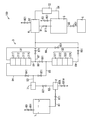
図1は、本発明の第1実施形態に係るアンモニア精製システム100の構成を示す図である。本実施形態のアンモニア精製システム100は、不純物が含まれる液体状の粗アンモニアを精製するシステムである。アンモニア精製システム100は、貯留手段である原料貯留タンク1、気化手段である気化器2、吸着手段である吸着ユニット3、分縮手段であるコンデンサ4、および回収タンク5を含んで構成される。   FIG. 1 is a diagram showing a configuration of an ammonia purification system 100 according to the first embodiment of the present invention. The ammonia purification system 100 of this embodiment is a system for purifying liquid crude ammonia containing impurities. The ammonia purification system 100 includes a raw material storage tank 1 that is a storage means, a vaporizer 2 that is a vaporization means, an adsorption unit 3 that is an adsorption means, a condenser 4 that is a partial reduction means, and a recovery tank 5.

原料貯留タンク1は、粗アンモニアを貯留するものである。本実施形態において、原料貯留タンク1に貯留される粗アンモニアは、純度99重量%以上、好ましくは純度99.0〜99.9重量%である。   The raw material storage tank 1 stores crude ammonia. In the present embodiment, the crude ammonia stored in the raw material storage tank 1 has a purity of 99% by weight or more, preferably a purity of 99.0 to 99.9% by weight.

原料貯留タンク1は、耐圧性および耐腐食性を有する保温容器であれば特に制限されるものではない。この原料貯留タンク1は、粗アンモニアを液体状のアンモニアとして貯留し、所定の温度および圧力になるように制御されている。原料貯留タンク1は、円柱状の内部空間を有し、その内部空間に液体状の粗アンモニアを貯留した状態で、原料貯留タンク1の上部には気相が形成され、下部には液相が形成されている。   The raw material storage tank 1 is not particularly limited as long as it is a heat insulating container having pressure resistance and corrosion resistance. The raw material storage tank 1 stores crude ammonia as liquid ammonia and is controlled so as to have a predetermined temperature and pressure. The raw material storage tank 1 has a cylindrical internal space, and in the state where liquid crude ammonia is stored in the internal space, a gas phase is formed in the upper part of the raw material storage tank 1, and a liquid phase is formed in the lower part. Is formed.

原料貯留タンク1には、原料貯留タンク1と外部とを連通し、気相に分配された揮発性の高い不純物(たとえば、水素、窒素、酸素、アルゴン、一酸化炭素、二酸化炭素など)を外部に排出するための流路となる排気配管80が接続されている。この排気配管80には、排気配管80における流路を開放または閉鎖する排気バルブ801が設けられている。本実施形態のアンモニア精製システム100は、排気バルブ801を開放させることで、原料貯留タンク1内に貯留される粗アンモニアから揮発性の高い不純物を排出除去する排出動作が実施できるように構成されている。具体的には、液体状の粗アンモニアを原料貯留タンク1に0.5〜3日間貯留した後、排気バルブ801を10〜300分間開放させる。これによって、原料貯留タンク1に形成された気相に分配された粗アンモニア中の揮発性の高い不純物を、排気配管80を介して排出することができる。   The raw material storage tank 1 communicates with the raw material storage tank 1 and the outside, and highly volatile impurities distributed in the gas phase (for example, hydrogen, nitrogen, oxygen, argon, carbon monoxide, carbon dioxide, etc.) are externally supplied. An exhaust pipe 80 serving as a flow path for discharging is connected. The exhaust pipe 80 is provided with an exhaust valve 801 that opens or closes the flow path in the exhaust pipe 80. The ammonia purification system 100 according to the present embodiment is configured such that a discharge operation for discharging and removing highly volatile impurities from the crude ammonia stored in the raw material storage tank 1 can be performed by opening the exhaust valve 801. Yes. Specifically, after liquid crude ammonia is stored in the raw material storage tank 1 for 0.5 to 3 days, the exhaust valve 801 is opened for 10 to 300 minutes. Thereby, highly volatile impurities in the crude ammonia distributed in the gas phase formed in the raw material storage tank 1 can be discharged through the exhaust pipe 80.

原料貯留タンク1に貯留される粗アンモニアは、気化器2に導出される。原料貯留タンク1から気化器2に粗アンモニアが導出される際には、原料貯留タンク1に形成される液相から液体状の粗アンモニアとして導出される。原料の粗アンモニアは、製品ロットごとに不純物濃度のばらつきが大きい場合がある。このように、不純物濃度のばらつきが大きい粗アンモニアを原料貯留タンク1の気相から導出するようにした場合、気相における成分組成のばらつきが大きく、最終的に精製されるアンモニアの純度に大きなばらつきが発生してしまうおそれがある。本実施形態のアンモニア精製システム100は、原料貯留タンク1の液相から液体状の粗アンモニアが導出されるように構成されているので、原料に不純物濃度のばらつきが大きい粗アンモニアが用いられた場合においても、最終的に精製されるアンモニアの純度に大きなばらつきが発生するのを防止することができる。   Crude ammonia stored in the raw material storage tank 1 is led to the vaporizer 2. When crude ammonia is derived from the raw material storage tank 1 to the vaporizer 2, it is derived as liquid crude ammonia from the liquid phase formed in the raw material storage tank 1. Crude ammonia as a raw material may have a large variation in impurity concentration between product lots. As described above, when crude ammonia having a large impurity concentration variation is derived from the gas phase of the raw material storage tank 1, the component composition in the gas phase varies greatly and the purity of the finally purified ammonia varies greatly. May occur. Since the ammonia purification system 100 of the present embodiment is configured such that liquid crude ammonia is derived from the liquid phase of the raw material storage tank 1, when crude ammonia having a large variation in impurity concentration is used as the raw material, In this case, it is possible to prevent a large variation in the purity of the finally purified ammonia.

原料貯留タンク1と気化器2との間には第1配管81が接続されており、原料貯留タンク1から導出された液体状の粗アンモニアは、第1配管81を流れて気化器2に供給される。第1配管81には、第1配管81における流路を開放または閉鎖する第1バルブ811が設けられている。液体状の粗アンモニアの気化器2への供給時には、第1バルブ811が開放されて、原料貯留タンク1から気化器2に向けて第1配管81内を液体状の粗アンモニアが流れる。   A first pipe 81 is connected between the raw material storage tank 1 and the vaporizer 2, and liquid crude ammonia derived from the raw material storage tank 1 flows through the first pipe 81 and is supplied to the vaporizer 2. Is done. The first pipe 81 is provided with a first valve 811 that opens or closes the flow path in the first pipe 81. When supplying the liquid crude ammonia to the vaporizer 2, the first valve 811 is opened, and the liquid crude ammonia flows in the first pipe 81 from the raw material storage tank 1 toward the vaporizer 2.

気化器2は、原料貯留タンク1から導出された液体状の粗アンモニアの一部を気化する。すなわち、気化器2は、液体状の粗アンモニアを加熱して所定の気化率で気化して気相成分と液相成分とに分離し、気体状のアンモニアを導出する。気化器2は、液体状の粗アンモニアの一部を気化するので、粗アンモニア中に含有される揮発性の低い不純物(たとえば、水分、炭素数6以上の炭化水素など)が液相に残り、揮発性の低い不純物が低減された気体状のアンモニアを導出することができる。   The vaporizer 2 vaporizes a part of the liquid crude ammonia derived from the raw material storage tank 1. That is, the vaporizer 2 heats liquid crude ammonia, vaporizes it at a predetermined vaporization rate, separates it into a gas phase component and a liquid phase component, and derives gaseous ammonia. Since the vaporizer 2 vaporizes a part of the liquid crude ammonia, low-volatile impurities (for example, moisture, hydrocarbons having 6 or more carbon atoms) contained in the crude ammonia remain in the liquid phase, Gaseous ammonia in which impurities with low volatility are reduced can be derived.

本実施形態では、気化器2は、原料貯留タンク1から導出された液体状の粗アンモニアを、90〜95体積%の気化率で気化して気相成分と液相成分とに分離する。この場合には、原料貯留タンク1から導出された液体状の粗アンモニアの90〜95体積%が気相成分となり、5〜10体積%が液相成分となる。   In the present embodiment, the vaporizer 2 vaporizes the liquid crude ammonia derived from the raw material storage tank 1 at a vaporization rate of 90 to 95% by volume and separates it into a gas phase component and a liquid phase component. In this case, 90 to 95% by volume of the liquid crude ammonia derived from the raw material storage tank 1 becomes a gas phase component, and 5 to 10% by volume becomes a liquid phase component.

気化器2には、第2バルブ821が設けられた第2配管82と、排出バルブ801Aが設けられた排出配管80Aとが接続されている。なお、第2配管82は、気化器2から導出された気体状のアンモニアが吸着ユニット3に向けて流れる配管であり、流量調整器71に接続されている。気化器2において、液相成分としてアンモニアから分離除去された揮発性の低い不純物は、排出バルブ801Aが開放された状態で、排出配管80Aを流れてシステム外部に排出される。また、気化器2において、気相成分として得られた気体状のアンモニアは、第2バルブ821が開放された状態で、第2配管82を流れて流量調整器71に供給される。   The vaporizer 2 is connected to a second pipe 82 provided with a second valve 821 and a discharge pipe 80A provided with a discharge valve 801A. The second pipe 82 is a pipe through which gaseous ammonia derived from the vaporizer 2 flows toward the adsorption unit 3, and is connected to the flow rate regulator 71. In the vaporizer 2, the low-volatile impurities separated and removed from the ammonia as a liquid phase component flow through the discharge pipe 80A and are discharged to the outside of the system with the discharge valve 801A being opened. In the vaporizer 2, gaseous ammonia obtained as a gas phase component flows through the second pipe 82 and is supplied to the flow rate regulator 71 with the second valve 821 opened.

流量調整器71には、第3配管83が接続されており、この第3配管83は、流量調整器71に接続されている側とは反対側の端部が分岐されている。第3配管83における前記端部の、分岐された一方は、後述する第1吸着塔31の塔頂部に接続される第4配管84に接続され、分岐された他方は、後述する第2吸着塔32の塔頂部に接続される第5配管85に接続されている。   A third pipe 83 is connected to the flow regulator 71, and the end of the third pipe 83 opposite to the side connected to the flow regulator 71 is branched. One of the ends of the third pipe 83 branched is connected to a fourth pipe 84 connected to the tower top of the first adsorption tower 31 described later, and the other branched branch is a second adsorption tower described later. It is connected to the 5th piping 85 connected to 32 tower tops.

第4配管84には、第4配管84における流路を開放または閉鎖する第4バルブ841が設けられている。また、第5配管85には、第5配管85における流路を開放または閉鎖する第5バルブ851が設けられている。流量調整器71によって流量が調整された気体状のアンモニアは、第4バルブ841が開放され、かつ第5バルブ851が閉鎖された状態で、第3配管83および第4配管84を流れ、第1吸着塔31に供給される。また、流量調整器71によって流量が調整された気体状のアンモニアは、第5バルブ851が開放され、かつ第4バルブ841が閉鎖された状態で、第3配管83および第5配管85を流れ、第2吸着塔32に供給される。すなわち、第1吸着塔31と第2吸着塔32とは、第4配管84および第5配管85を介して並列接続されている。   The fourth pipe 84 is provided with a fourth valve 841 that opens or closes the flow path in the fourth pipe 84. The fifth pipe 85 is provided with a fifth valve 851 that opens or closes the flow path in the fifth pipe 85. The gaseous ammonia whose flow rate is adjusted by the flow rate regulator 71 flows through the third pipe 83 and the fourth pipe 84 in a state where the fourth valve 841 is opened and the fifth valve 851 is closed. It is supplied to the adsorption tower 31. The gaseous ammonia whose flow rate has been adjusted by the flow rate regulator 71 flows through the third pipe 83 and the fifth pipe 85 with the fifth valve 851 opened and the fourth valve 841 closed. It is supplied to the second adsorption tower 32. That is, the first adsorption tower 31 and the second adsorption tower 32 are connected in parallel via the fourth pipe 84 and the fifth pipe 85.

吸着ユニット3は、気化器2から導出された気体状のアンモニアに含まれる不純物を吸着除去して精製する。吸着ユニット3は、吸着部である第1吸着塔31および第2吸着塔32を含んで構成される。   The adsorption unit 3 adsorbs and removes impurities contained in gaseous ammonia derived from the vaporizer 2 for purification. The adsorption unit 3 includes a first adsorption tower 31 and a second adsorption tower 32 which are adsorption units.

第1吸着塔31は、塔頂部から塔底部に向かって(アンモニアの流れ方向上流側から下流側に向かって)順番に、塔頂吸着層311、第1中間吸着層312、第2中間吸着層313、および塔底吸着層314が積層された積層構造を有する。   The first adsorption tower 31 is, in order from the tower top to the tower bottom (from the upstream side to the downstream side in the ammonia flow direction), the tower top adsorption layer 311, the first intermediate adsorption layer 312, and the second intermediate adsorption layer. 313 and a tower bottom adsorbing layer 314 are stacked.

塔頂吸着層311は、第1吸着剤を含む層であり、第1吸着剤層としての機能を有する。第1吸着剤は、水に対して高い吸着能を有する多孔質吸着剤である。このような第1吸着剤としては、たとえば、活性炭、MS−13X(細孔径9Åの多孔質合成ゼオライト)、活性アルミナなどが挙げられる。本実施形態では、第1吸着剤として、活性炭が用いられる。   The tower top adsorption layer 311 is a layer containing a first adsorbent and has a function as a first adsorbent layer. The first adsorbent is a porous adsorbent having a high adsorbability for water. Examples of such a first adsorbent include activated carbon, MS-13X (porous synthetic zeolite having a pore size of 9 mm), activated alumina, and the like. In the present embodiment, activated carbon is used as the first adsorbent.

第1中間吸着層312は、第2吸着剤を含む層であり、第2吸着剤層としての機能を有する。第2吸着剤は、炭素数5未満の有機化合物(炭化水素、アルコール、エーテルなど)に対して高い吸着能を有する多孔質吸着剤である。このような第2吸着剤としては、たとえば、MS−3A(細孔径3Åの多孔質合成ゼオライト)、MS−4A(細孔径4Åの多孔質合成ゼオライト)、MS−5A(細孔径5Åの多孔質合成ゼオライト)、MS−13X(細孔径9Åの多孔質合成ゼオライト)などの親水性ゼオライト、ハイシリカ型(シリカ/アルミナ比が高い)ゼオライトなどの疎水性ゼオライト、シリカゲルなどが挙げられる。また、第2中間吸着層313は、第1中間吸着層312と同様に、第2吸着剤を含む層であり、第2吸着剤層としての機能を有する。ただし、第1中間吸着層312と第2中間吸着層313とは、第2吸着剤を含む層であることで同じであるけれども、互いに種類が異なる吸着剤を用いる。   The first intermediate adsorption layer 312 is a layer containing a second adsorbent and has a function as a second adsorbent layer. The second adsorbent is a porous adsorbent having a high adsorbability for organic compounds having less than 5 carbon atoms (hydrocarbon, alcohol, ether, etc.). Examples of such second adsorbent include MS-3A (porous synthetic zeolite having a pore diameter of 3 mm), MS-4A (porous synthetic zeolite having a pore diameter of 4 mm), and MS-5A (porous having a pore diameter of 5 mm). Synthetic zeolite), hydrophilic zeolite such as MS-13X (porous synthetic zeolite having a pore size of 9 mm), hydrophobic zeolite such as high silica type (high silica / alumina ratio) zeolite, silica gel and the like. Similarly to the first intermediate adsorption layer 312, the second intermediate adsorption layer 313 is a layer containing a second adsorbent and has a function as a second adsorbent layer. However, although the first intermediate adsorption layer 312 and the second intermediate adsorption layer 313 are the same because they are layers containing the second adsorbent, different types of adsorbents are used.

塔底吸着層314は、第3吸着剤を含む層であり、第3吸着剤層としての機能を有する。第3吸着剤は、炭素数5以上の有機化合物(炭化水素など)および水に対して高い吸着能を有する多孔質吸着剤である。このような第3吸着剤としては、活性炭、MS−13Xなどが挙げられる。   The tower bottom adsorption layer 314 is a layer containing a third adsorbent and has a function as a third adsorbent layer. The third adsorbent is a porous adsorbent having high adsorbability for organic compounds having 5 or more carbon atoms (such as hydrocarbons) and water. Examples of such a third adsorbent include activated carbon and MS-13X.

第1吸着塔31における積層構造について、具体例を挙げて説明する。第1の具体例では、塔頂吸着層311は、第1吸着剤として活性炭(GG、クラレケミカル株式会社製)を含む層であり、第1中間吸着層312は、第2吸着剤として親水性ゼオライト(MS−3A、東ソー株式会社製)を含む層であり、第2中間吸着層313は、第2吸着剤としてシリカゲル(シルビードN、水澤化学工業株式会社製)を含む層であり、塔底吸着層314は、第3吸着剤として活性炭(GG、クラレケミカル株式会社製)を含む層である。   The laminated structure in the first adsorption tower 31 will be described with a specific example. In the first specific example, the tower top adsorption layer 311 is a layer containing activated carbon (GG, manufactured by Kuraray Chemical Co., Ltd.) as the first adsorbent, and the first intermediate adsorption layer 312 is hydrophilic as the second adsorbent. It is a layer containing zeolite (MS-3A, manufactured by Tosoh Corporation), and the second intermediate adsorption layer 313 is a layer containing silica gel (Sylbeed N, manufactured by Mizusawa Chemical Co., Ltd.) as the second adsorbent, The adsorption layer 314 is a layer containing activated carbon (GG, manufactured by Kuraray Chemical Co., Ltd.) as a third adsorbent.

第2の具体例では、塔頂吸着層311は、第1吸着剤として活性炭(GG、クラレケミカル株式会社製)を含む層であり、第1中間吸着層312は、第2吸着剤として親水性ゼオライト(MS−3A、東ソー株式会社製)を含む層であり、第2中間吸着層313は、第2吸着剤としてシリカゲル(シルビードN、水澤化学工業株式会社製)を含む層であり、塔底吸着層314は、第3吸着剤としてMS−13X(SA−600A、東ソー株式会社製)を含む層である。   In the second specific example, the tower top adsorption layer 311 is a layer containing activated carbon (GG, manufactured by Kuraray Chemical Co., Ltd.) as the first adsorbent, and the first intermediate adsorption layer 312 is hydrophilic as the second adsorbent. It is a layer containing zeolite (MS-3A, manufactured by Tosoh Corporation), and the second intermediate adsorption layer 313 is a layer containing silica gel (Sylbeed N, manufactured by Mizusawa Chemical Co., Ltd.) as the second adsorbent, The adsorption layer 314 is a layer containing MS-13X (SA-600A, manufactured by Tosoh Corporation) as a third adsorbent.

第3の具体例では、塔頂吸着層311は、第1吸着剤として活性炭(GG、クラレケミカル株式会社製)を含む層であり、第1中間吸着層312は、第2吸着剤として親水性ゼオライト(MS−4A、東ソー株式会社製)を含む層であり、第2中間吸着層313は、第2吸着剤として疎水性ゼオライト(HSZ−300、シリカ/アルミナ比=10、東ソー株式会社製)を含む層であり、塔底吸着層314は、第3吸着剤としてMS−13X(SA−600A、東ソー株式会社製)を含む層である。   In the third specific example, the tower top adsorption layer 311 is a layer containing activated carbon (GG, manufactured by Kuraray Chemical Co., Ltd.) as the first adsorbent, and the first intermediate adsorption layer 312 is hydrophilic as the second adsorbent. It is a layer containing zeolite (MS-4A, manufactured by Tosoh Corporation), and the second intermediate adsorption layer 313 is a hydrophobic zeolite (HSZ-300, silica / alumina ratio = 10, manufactured by Tosoh Corporation) as the second adsorbent. The tower bottom adsorption layer 314 is a layer containing MS-13X (SA-600A, manufactured by Tosoh Corporation) as the third adsorbent.

第4の具体例では、塔頂吸着層311は、第1吸着剤として活性炭(GG、クラレケミカル株式会社製)を含む層であり、第1中間吸着層312は、第2吸着剤として親水性ゼオライト(MS−4A、東ソー株式会社製)を含む層であり、第2中間吸着層313は、第2吸着剤として疎水性ゼオライト(HSZ−300、シリカ/アルミナ比=10、東ソー株式会社製)を含む層であり、塔底吸着層314は、第3吸着剤としてMS−13X(SA−600A、東ソー株式会社製)と活性炭(GG、クラレケミカル株式会社製)との積層体を含む層である。   In the fourth specific example, the tower top adsorption layer 311 is a layer containing activated carbon (GG, manufactured by Kuraray Chemical Co., Ltd.) as the first adsorbent, and the first intermediate adsorption layer 312 is hydrophilic as the second adsorbent. It is a layer containing zeolite (MS-4A, manufactured by Tosoh Corporation), and the second intermediate adsorption layer 313 is a hydrophobic zeolite (HSZ-300, silica / alumina ratio = 10, manufactured by Tosoh Corporation) as the second adsorbent. The tower bottom adsorption layer 314 is a layer containing a laminate of MS-13X (SA-600A, manufactured by Tosoh Corporation) and activated carbon (GG, manufactured by Kuraray Chemical Co., Ltd.) as a third adsorbent. is there.

第2吸着塔32は、塔頂部から塔底部に向かって(アンモニアの流れ方向上流側から下流側に向かって)順番に、塔頂吸着層321、第1中間吸着層322、第2中間吸着層323、および塔底吸着層324が積層された積層構造を有する。   The second adsorption tower 32 has a tower top adsorption layer 321, a first intermediate adsorption layer 322, and a second intermediate adsorption layer in order from the tower top to the tower bottom (from the upstream to the downstream in the ammonia flow direction). 323 and a tower bottom adsorption layer 324 are laminated.

塔頂吸着層321は、前述した第1吸着塔31の塔頂吸着層311と同様に構成された、第1吸着剤を含む層であり、第1吸着剤層としての機能を有する。第1中間吸着層322は、前述した第1吸着塔31の第1中間吸着層312と同様に構成された、第2吸着剤を含む層であり、第2吸着剤層としての機能を有する。第2中間吸着層323は、前述した第1吸着塔31の第2中間吸着層313と同様に構成された、第2吸着剤を含む層であり、第2吸着剤層としての機能を有する。塔底吸着層324は、前述した第1吸着塔31の塔底吸着層314と同様に構成された、第3吸着剤を含む層であり、第3吸着剤層としての機能を有する。   The tower top adsorption layer 321 is a layer including the first adsorbent, which is configured in the same manner as the tower top adsorption layer 311 of the first adsorption tower 31 described above, and has a function as a first adsorbent layer. The 1st intermediate adsorption layer 322 is a layer containing the 2nd adsorbent comprised similarly to the 1st intermediate adsorption layer 312 of the 1st adsorption tower 31 mentioned above, and has a function as the 2nd adsorbent layer. The second intermediate adsorption layer 323 is a layer including the second adsorbent, which is configured in the same manner as the second intermediate adsorption layer 313 of the first adsorption tower 31 described above, and has a function as a second adsorbent layer. The tower bottom adsorption layer 324 is a layer including a third adsorbent, which is configured in the same manner as the tower bottom adsorption layer 314 of the first adsorption tower 31 described above, and has a function as a third adsorbent layer.

第1吸着塔31および第2吸着塔32で使用される、第1吸着剤、第2吸着剤および第3吸着剤は、加熱、減圧、加熱および減圧のいずれかの処理によって、吸着した不純物(水分および炭化水素などの有機化合物)を脱離させて再生することができる。たとえば、加熱処理によって吸着剤に吸着した不純物を脱離させる場合には、200〜350℃の温度下で加熱するようにすればよい。   The first adsorbent, the second adsorbent, and the third adsorbent used in the first adsorption tower 31 and the second adsorption tower 32 are adsorbed impurities (processed by heating, depressurization, heating, and depressurization). Organic compounds such as moisture and hydrocarbons) can be desorbed and regenerated. For example, when desorbing impurities adsorbed on the adsorbent by heat treatment, heating may be performed at a temperature of 200 to 350 ° C.

また、本実施形態のアンモニア精製システム100において、第1吸着塔31および第2吸着塔32は、温度が0〜60℃に制御され、圧力が0.1〜1.0MPaに制御される。第1吸着塔31および第2吸着塔32の温度が0℃未満の場合には、不純物の吸着除去時に発生する吸着熱を除去する冷却が必要となってエネルギ効率が低下するおそれがある。第1吸着塔31および第2吸着塔32の温度が60℃を超える場合には、吸着剤による不純物の吸着能が低下するおそれがある。また、第1吸着塔31および第2吸着塔32の圧力が0.1MPa未満の場合には、吸着剤による不純物の吸着能が低下するおそれがあり、圧力が1.0MPaを超える場合には、一定圧力に維持するために多くのエネルギが必要となり、エネルギ効率が低下するおそれがある。   Moreover, in the ammonia purification system 100 of this embodiment, the temperature of the first adsorption tower 31 and the second adsorption tower 32 is controlled to 0 to 60 ° C., and the pressure is controlled to 0.1 to 1.0 MPa. If the temperature of the first adsorption tower 31 and the second adsorption tower 32 is less than 0 ° C., cooling to remove the heat of adsorption generated during the adsorption removal of impurities may be required, which may reduce the energy efficiency. When the temperature of the 1st adsorption tower 31 and the 2nd adsorption tower 32 exceeds 60 degreeC, there exists a possibility that the adsorption capacity of the impurity by adsorbent may fall. Moreover, when the pressure of the 1st adsorption tower 31 and the 2nd adsorption tower 32 is less than 0.1 Mpa, there exists a possibility that the adsorption capability of the impurity by adsorption agent may fall, and when a pressure exceeds 1.0 Mpa, A large amount of energy is required to maintain a constant pressure, which may reduce energy efficiency.

また、第1吸着塔31および第2吸着塔32における線速度(リニアベロシティ)は、0.1〜10.0m/秒であることが好ましい。線速度が0.1m/秒未満の場合には、不純物の吸着除去に長時間を要するので好ましくなく、線速度が10.0m/秒を超える場合には、不純物の吸着除去時に発生する吸着熱の除去が充分に行われずに、吸着剤による不純物の吸着能が低下するおそれがある。なお、前記線速度は、第1吸着塔31または第2吸着塔32に気体状のアンモニアを単位時間あたりに供給する量を、NTPでのガス体積に換算し、各吸着塔31,32の空塔断面積で除算して求めた値である。   Moreover, it is preferable that the linear velocity (linear velocity) in the 1st adsorption tower 31 and the 2nd adsorption tower 32 is 0.1-10.0 m / sec. When the linear velocity is less than 0.1 m / sec, it is not preferable because it takes a long time to remove impurities, and when the linear velocity exceeds 10.0 m / sec, the heat of adsorption generated during the adsorption removal of impurities. In this case, the adsorption capacity of the impurities by the adsorbent may be lowered. The linear velocity is calculated by converting the amount of gaseous ammonia supplied to the first adsorption tower 31 or the second adsorption tower 32 per unit time into the gas volume of NTP and emptying the adsorption towers 31 and 32. It is the value obtained by dividing by the tower cross section.

また、本実施形態のアンモニア精製システム100では、第1吸着塔31および第2吸着塔32から導出されたアンモニアに含まれる不純物の濃度を分析することが好ましい。アンモニアに含まれる不純物の濃度を分析する装置としては、ガスクロマトグラフ分析装置(GC−PDD:パルス放電型検出器)を挙げることができる。このガスクロマトグラフ分析装置の具体例としては、たとえば、ジーエルサイエンス株式会社製のGC−4000を挙げることができる。ガスクロマトグラフ分析装置による分析結果に基づいて、後述のコンデンサ4における分縮条件(凝縮率の設定など)を設定するようにしてもよい。   In the ammonia purification system 100 of the present embodiment, it is preferable to analyze the concentration of impurities contained in the ammonia derived from the first adsorption tower 31 and the second adsorption tower 32. As a device for analyzing the concentration of impurities contained in ammonia, a gas chromatograph analyzer (GC-PDD: pulse discharge detector) can be exemplified. Specific examples of the gas chromatograph analyzer include GC-4000 manufactured by GL Sciences, Inc. Based on the analysis result by the gas chromatograph analyzer, a partial reduction condition (such as setting of the condensation rate) in the capacitor 4 described later may be set.

第1吸着塔31の塔底部には、第6配管86が接続されており、この第6配管86は、第1吸着塔31に接続されている側とは反対側の端部が分岐されている。第6配管86における前記端部の、分岐された一方は、後述するコンデンサ4に接続される第7配管87に接続され、分岐された他方は、第2吸着塔32の塔頂部に接続される第8配管88に接続されている。   A sixth pipe 86 is connected to the bottom of the first adsorption tower 31, and the sixth pipe 86 is branched at the end opposite to the side connected to the first adsorption tower 31. Yes. One of the ends of the sixth pipe 86 branched is connected to a seventh pipe 87 connected to the capacitor 4 described later, and the other branched is connected to the top of the second adsorption tower 32. It is connected to the eighth pipe 88.

第7配管87には、第7配管87における流路を開放または閉鎖する第7バルブ871が設けられている。また、第8配管88には、第8配管88における流路を開放または閉鎖する第8バルブ881が設けられている。第1吸着塔31によって不純物が吸着除去された気体状のアンモニアは、第7バルブ871が開放され、かつ第8バルブ881が閉鎖された状態で、第6配管86および第7配管87を流れ、コンデンサ4に供給される。また、第1吸着塔31によって不純物が吸着除去された気体状のアンモニアは、第8バルブ881が開放され、かつ第7バルブ871が閉鎖された状態で、第6配管86および第8配管88を流れ、第2吸着塔32に供給される。すなわち、第1吸着塔31と第2吸着塔32とは、第6配管86および第8配管88を介して直列接続されている。   The seventh pipe 87 is provided with a seventh valve 871 that opens or closes the flow path in the seventh pipe 87. The eighth pipe 88 is provided with an eighth valve 881 that opens or closes the flow path in the eighth pipe 88. The gaseous ammonia from which impurities have been adsorbed and removed by the first adsorption tower 31 flows through the sixth pipe 86 and the seventh pipe 87 with the seventh valve 871 opened and the eighth valve 881 closed. It is supplied to the capacitor 4. The gaseous ammonia from which impurities have been adsorbed and removed by the first adsorption tower 31 passes through the sixth pipe 86 and the eighth pipe 88 with the eighth valve 881 opened and the seventh valve 871 closed. The flow is supplied to the second adsorption tower 32. That is, the first adsorption tower 31 and the second adsorption tower 32 are connected in series via the sixth pipe 86 and the eighth pipe 88.

また、第2吸着塔32の塔底部には、第9配管89が接続されており、この第9配管89の、第2吸着塔32に接続されている側とは反対側の端部は、コンデンサ4に接続されている。第9配管89には、第9配管89における流路を開放または閉鎖する第9バルブ891が設けられている。この第9配管89には、第9バルブ891に対してアンモニアの流れ方向下流側に、第9配管89から分岐する第10配管90が接続されている。この第10配管90には、第10配管90における流路を開放または閉鎖する第10バルブ901が設けられている。さらに、この第10配管90の、第9配管89に接続されている側とは反対側の端部は、第1吸着塔31の塔頂部に接続されている。   Further, a ninth pipe 89 is connected to the bottom of the second adsorption tower 32, and the end of the ninth pipe 89 opposite to the side connected to the second adsorption tower 32 is The capacitor 4 is connected. The ninth pipe 89 is provided with a ninth valve 891 that opens or closes the flow path in the ninth pipe 89. A tenth pipe 90 branched from the ninth pipe 89 is connected to the ninth pipe 89 downstream of the ninth valve 891 in the ammonia flow direction. The tenth pipe 90 is provided with a tenth valve 901 that opens or closes the flow path in the tenth pipe 90. Further, the end of the tenth pipe 90 opposite to the side connected to the ninth pipe 89 is connected to the top of the first adsorption tower 31.

第2吸着塔32によって不純物が吸着除去された気体状のアンモニアは、第9バルブ891が開放され、かつ第10バルブ901が閉鎖された状態で、第9配管89を流れ、コンデンサ4に供給される。また、第2吸着塔32によって不純物が吸着除去された気体状のアンモニアは、第9バルブ891が開放され、かつ第10バルブ901が開放された状態で、第9配管89および第10配管90を流れ、第1吸着塔31に供給される。   The gaseous ammonia from which impurities have been adsorbed and removed by the second adsorption tower 32 flows through the ninth pipe 89 and is supplied to the capacitor 4 with the ninth valve 891 opened and the tenth valve 901 closed. The The gaseous ammonia from which impurities have been adsorbed and removed by the second adsorption tower 32 passes through the ninth pipe 89 and the tenth pipe 90 with the ninth valve 891 opened and the tenth valve 901 opened. The flow is supplied to the first adsorption tower 31.

以上のように構成された吸着ユニット3では、第1吸着塔31と第2吸着塔32との接続を、4つのパターンで変更可能である。   In the adsorption unit 3 configured as described above, the connection between the first adsorption tower 31 and the second adsorption tower 32 can be changed in four patterns.

第1の接続パターンでは、第4バルブ841および第7バルブ871を開放させ、第5バルブ851、第8バルブ881、第9バルブ891、および第10バルブ901を閉鎖させる。この第1の接続パターンでは、気化器2から導出され、流量調整器71によって流量が調整された気体状のアンモニアは、第4配管84を流れて第1吸着塔31に供給される。そして、第1吸着塔31から導出された精製後の気体状のアンモニアは、第6配管86および第7配管87を流れてコンデンサ4に供給される。このような第1の接続パターンでは、気化器2から導出された気体状のアンモニアを、第1吸着塔31のみで精製する。第1吸着塔31で吸着除去している間に、使用済みの第2吸着塔32で再度吸着除去動作が可能なように、使用済みの第2吸着塔32を再生処理することができる。   In the first connection pattern, the fourth valve 841 and the seventh valve 871 are opened, and the fifth valve 851, the eighth valve 881, the ninth valve 891, and the tenth valve 901 are closed. In the first connection pattern, gaseous ammonia that is derived from the vaporizer 2 and whose flow rate is adjusted by the flow rate regulator 71 flows through the fourth pipe 84 and is supplied to the first adsorption tower 31. Then, the purified gaseous ammonia derived from the first adsorption tower 31 flows through the sixth pipe 86 and the seventh pipe 87 and is supplied to the capacitor 4. In such a first connection pattern, gaseous ammonia derived from the vaporizer 2 is purified only by the first adsorption tower 31. During the adsorption removal by the first adsorption tower 31, the used second adsorption tower 32 can be regenerated so that the adsorption removal operation can be performed again by the used second adsorption tower 32.

第2の接続パターンでは、第5バルブ851および第9バルブ891を開放させ、第4バルブ841、第7バルブ871、第8バルブ881、および第10バルブ901を閉鎖させる。この第2の接続パターンでは、気化器2から導出され、流量調整器71によって流量が調整された気体状のアンモニアは、第5配管85を流れて第2吸着塔32に供給される。そして、第2吸着塔32から導出された精製後の気体状のアンモニアは、第9配管89を流れてコンデンサ4に供給される。このような第2の接続パターンでは、気化器2から導出された気体状のアンモニアを、第2吸着塔32のみで精製する。第2吸着塔32で吸着除去している間に、使用済みの第1吸着塔31で再度吸着除去動作が可能なように、使用済みの第1吸着塔31を再生処理することができる。   In the second connection pattern, the fifth valve 851 and the ninth valve 891 are opened, and the fourth valve 841, the seventh valve 871, the eighth valve 881, and the tenth valve 901 are closed. In this second connection pattern, gaseous ammonia derived from the vaporizer 2 and whose flow rate is adjusted by the flow rate regulator 71 flows through the fifth pipe 85 and is supplied to the second adsorption tower 32. The purified gaseous ammonia derived from the second adsorption tower 32 flows through the ninth pipe 89 and is supplied to the capacitor 4. In such a second connection pattern, gaseous ammonia derived from the vaporizer 2 is purified only by the second adsorption tower 32. During the adsorption removal by the second adsorption tower 32, the used first adsorption tower 31 can be regenerated so that the adsorption removal operation can be performed again by the used first adsorption tower 31.

第3の接続パターンでは、第4バルブ841、第8バルブ881、および第9バルブ891を開放させ、第5バルブ851、第7バルブ871、および第10バルブ901を閉鎖させる。この第3の接続パターンでは、気化器2から導出され、流量調整器71によって流量が調整された気体状のアンモニアは、第4配管84を流れて第1吸着塔31に供給される。第1吸着塔31から導出された精製後の気体状のアンモニアは、第6配管86および第8配管88を流れて第2吸着塔3に供給される。そして、第2吸着塔32から導出された精製後の気体状のアンモニアは、第9配管89を流れてコンデンサ4に供給される。このような第3の接続パターンでは、気化器2から導出された気体状のアンモニアを、第1吸着塔31および第2吸着塔32で精製する。気化器2から導出された気体状のアンモニアに含まれる不純物を、直列接続された第1吸着塔31および第2吸着塔32で吸着除去することができるので、不純物に対する吸着除去能力を向上することができる。   In the third connection pattern, the fourth valve 841, the eighth valve 881, and the ninth valve 891 are opened, and the fifth valve 851, the seventh valve 871, and the tenth valve 901 are closed. In the third connection pattern, gaseous ammonia that is derived from the vaporizer 2 and whose flow rate is adjusted by the flow rate regulator 71 flows through the fourth pipe 84 and is supplied to the first adsorption tower 31. The purified gaseous ammonia derived from the first adsorption tower 31 flows through the sixth pipe 86 and the eighth pipe 88 and is supplied to the second adsorption tower 3. The purified gaseous ammonia derived from the second adsorption tower 32 flows through the ninth pipe 89 and is supplied to the capacitor 4. In such a third connection pattern, gaseous ammonia derived from the vaporizer 2 is purified by the first adsorption tower 31 and the second adsorption tower 32. Impurities contained in gaseous ammonia derived from the vaporizer 2 can be adsorbed and removed by the first adsorbing tower 31 and the second adsorbing tower 32 connected in series, so that the ability to adsorb and remove impurities can be improved. Can do.

第4の接続パターンでは、第4バルブ841、第8バルブ881、第9バルブ891、および第10バルブ901を開放させ、第5バルブ851および第7バルブ871を閉鎖させる。この第4の接続パターンでは、気化器2から導出され、流量調整器71によって流量が調整された気体状のアンモニアは、第4配管84を流れて第1吸着塔31に供給される。第1吸着塔31から導出された精製後の気体状のアンモニアは、第6配管86および第8配管88を流れて第2吸着塔32に供給される。第2吸着塔32から導出された精製後の気体状のアンモニアは、第9配管89および第10配管90を流れて第1吸着塔31に再度供給され、第1吸着塔31および第2吸着塔32による吸着除去動作が繰り返される。そして、開放されていた第10バルブ901を閉鎖させた時点で、第2吸着塔32から導出された気体状のアンモニアが、第9配管89を流れてコンデンサ4に供給される。このような第4の接続パターンでは、気化器2から導出された気体状のアンモニアを、第1吸着塔31および第2吸着塔32で繰り返し精製することができる。   In the fourth connection pattern, the fourth valve 841, the eighth valve 881, the ninth valve 891, and the tenth valve 901 are opened, and the fifth valve 851 and the seventh valve 871 are closed. In the fourth connection pattern, gaseous ammonia that is derived from the vaporizer 2 and whose flow rate is adjusted by the flow rate regulator 71 flows through the fourth pipe 84 and is supplied to the first adsorption tower 31. The purified gaseous ammonia derived from the first adsorption tower 31 flows through the sixth pipe 86 and the eighth pipe 88 and is supplied to the second adsorption tower 32. The purified gaseous ammonia derived from the second adsorption tower 32 flows through the ninth pipe 89 and the tenth pipe 90 and is supplied again to the first adsorption tower 31, and the first adsorption tower 31 and the second adsorption tower are supplied. The adsorption removal operation by 32 is repeated. When the opened tenth valve 901 is closed, gaseous ammonia derived from the second adsorption tower 32 flows through the ninth pipe 89 and is supplied to the condenser 4. In such a fourth connection pattern, gaseous ammonia derived from the vaporizer 2 can be repeatedly purified by the first adsorption tower 31 and the second adsorption tower 32.

第1吸着塔31または第2吸着塔32から導出された気体状のアンモニアは、コンデンサ4に供給される。コンデンサ4は、第1吸着塔31または第2吸着塔32から導出された気体状のアンモニアを分縮して気相成分と液相成分とに分離することで、アンモニア中に含有される水素、窒素、酸素、アルゴン、一酸化炭素、二酸化炭素などの、揮発性の高い不純物を気相成分として分離除去し、液相成分として精製された液体状のアンモニアを得る。   Gaseous ammonia derived from the first adsorption tower 31 or the second adsorption tower 32 is supplied to the condenser 4. Capacitor 4 degenerates gaseous ammonia derived from first adsorption tower 31 or second adsorption tower 32 and separates it into a gas phase component and a liquid phase component, whereby hydrogen contained in ammonia, Highly volatile impurities such as nitrogen, oxygen, argon, carbon monoxide and carbon dioxide are separated and removed as a gas phase component to obtain liquid ammonia purified as a liquid phase component.

コンデンサ4としては、多管式コンデンサ、プレート式熱交換器などが挙げられるが、本実施形態では、コンデンサ4として多管式コンデンサを用いる。コンデンサ4は、第1吸着塔31または第2吸着塔32から導出された気体状のアンモニアの70〜99体積%を凝縮して気相成分と液相成分とに分離する。この場合には、第1吸着塔31または第2吸着塔32から導出された気体状のアンモニアの一部である1〜30体積%が気相成分となるように凝縮して、気相成分と液相成分とに分離することになる。これによって、吸着除去後の気体状のアンモニアに含まれる揮発性の高い不純物を気相成分として分離除去し、液相成分として精製された液体状のアンモニアを収率よく得ることができる。   Examples of the condenser 4 include a multitubular condenser and a plate heat exchanger. In this embodiment, a multitubular condenser is used as the condenser 4. The condenser 4 condenses 70 to 99% by volume of gaseous ammonia derived from the first adsorption tower 31 or the second adsorption tower 32 and separates it into a gas phase component and a liquid phase component. In this case, 1 to 30% by volume, which is a part of gaseous ammonia derived from the first adsorption tower 31 or the second adsorption tower 32, is condensed so as to become a gas phase component, It separates into a liquid phase component. Thus, highly volatile impurities contained in the gaseous ammonia after adsorption removal can be separated and removed as a gas phase component, and liquid ammonia purified as a liquid phase component can be obtained with high yield.

また、コンデンサ4における凝縮条件としては、第1吸着塔31または第2吸着塔32から導出された気体状のアンモニアの一部が液体となるような条件であれば限定されるものではなく、温度、圧力および時間を適宜設定すればよい。本実施形態では、コンデンサ4は、第1吸着塔31または第2吸着塔32から導出された気体状のアンモニアを、−77〜40℃の温度下で凝縮して気相成分と液相成分とに分離するように構成されるのが好ましい。これによって、第1吸着塔31または第2吸着塔32から導出された気体状のアンモニアを効率よく凝縮して精製された液体状のアンモニアを得ることができるとともに、その液体状のアンモニアの純度を高めることができる。コンデンサ4における気体状のアンモニアに対する凝縮時の温度が、−77℃未満である場合には、冷却するのに多くのエネルギを要するので好ましくなく、40℃を超える場合には、アンモニアの一部が凝縮されて得られる液体状のアンモニアに含まれてくる不純物濃度が高くなってくるので好ましくない。   Further, the condensation condition in the condenser 4 is not limited as long as a part of the gaseous ammonia led out from the first adsorption tower 31 or the second adsorption tower 32 becomes a liquid. The pressure and time may be set as appropriate. In the present embodiment, the capacitor 4 condenses gaseous ammonia derived from the first adsorption tower 31 or the second adsorption tower 32 at a temperature of −77 to 40 ° C. It is preferable that it is comprised so that it may isolate | separate. As a result, it is possible to obtain a purified liquid ammonia by efficiently condensing gaseous ammonia derived from the first adsorption tower 31 or the second adsorption tower 32, and to reduce the purity of the liquid ammonia. Can be increased. When the temperature at the time of condensation with respect to gaseous ammonia in the condenser 4 is less than −77 ° C., it is not preferable because it requires a lot of energy for cooling. Since the concentration of impurities contained in the liquid ammonia obtained by condensation increases, it is not preferable.

また、コンデンサ4は、第1吸着塔31または第2吸着塔32から導出された気体状のアンモニアを、0.007〜2.0MPaの圧力下で凝縮して気相成分と液相成分とに分離するように構成されるのが好ましい。コンデンサ4における気体状のアンモニアに対する凝縮時の圧力が、0.007MPa未満である場合には、アンモニアを凝縮させる温度が低くなるので、冷却するのに多くのエネルギが必要となって好ましくなく、2.0MPaを超える場合には、アンモニアを凝縮させる温度が高くなるので、アンモニアの一部が凝縮されて得られる液体状のアンモニアに含まれてくる不純物濃度が高くなって好ましくない。   The capacitor 4 also condenses gaseous ammonia derived from the first adsorption tower 31 or the second adsorption tower 32 under a pressure of 0.007 to 2.0 MPa into a gas phase component and a liquid phase component. It is preferably configured to separate. When the pressure at the time of condensation with respect to gaseous ammonia in the condenser 4 is less than 0.007 MPa, the temperature for condensing ammonia is lowered, so that a lot of energy is required for cooling, which is not preferable. If it exceeds 0.0 MPa, the temperature at which ammonia is condensed becomes high, which is not preferable because the concentration of impurities contained in liquid ammonia obtained by condensing a part of ammonia is high.

本実施形態のアンモニア精製システム100において、コンデンサ4は、第1吸着塔31または第2吸着塔32から導出された気体状のアンモニアの一部を凝縮して気相成分と液相成分とに分離するので、揮発性の高い不純物を気相成分として分離除去し、液相成分として精製された液体状のアンモニアを得ることができる。そのため、従来技術のように蒸留手段を設けなくても、簡単化されたシステムでアンモニアを精製することができる。   In the ammonia purification system 100 of the present embodiment, the condenser 4 condenses part of the gaseous ammonia derived from the first adsorption tower 31 or the second adsorption tower 32 and separates it into a gas phase component and a liquid phase component. Therefore, highly volatile impurities can be separated and removed as a gas phase component, and liquid ammonia purified as a liquid phase component can be obtained. Therefore, ammonia can be purified with a simplified system without providing distillation means as in the prior art.

粗アンモニア中に含有される不純物を精密蒸留により分離除去する場合、還流を掛けながらの蒸留であるので、蒸留塔で液体状のアンモニアを加熱蒸発させて気体状のアンモニアとし、一方、蒸留塔の塔頂部のコンデンサで精留塔からの気体状のアンモニアを凝縮させて液体状のアンモニアとする操作を繰り返すことになる。そのため、精留操作においては大きなエネルギをその操作に投入することになる。   When the impurities contained in the crude ammonia are separated and removed by precision distillation, since distillation is performed while refluxing, liquid ammonia is heated and evaporated in a distillation column to form gaseous ammonia. The operation of condensing gaseous ammonia from the rectifying column with the condenser at the top of the column to form liquid ammonia is repeated. Therefore, large energy is input to the rectification operation.

これに対して、コンデンサ4における分縮によりアンモニア中に含有される不純物を分離除去する場合には、気体状のアンモニアを1回凝縮させるだけであるので、それに必要なエネルギが少なくて済む。このように、精留によるアンモニアの精製方法と比較して、コンデンサ4における分縮による精製方法は、短時間に高純度のアンモニアが得られるばかりではなく、エネルギ的にも大きなメリットがあることがわかる。   On the other hand, when the impurities contained in the ammonia are separated and removed by the partial condensation in the condenser 4, the gaseous ammonia is only condensed once, so that less energy is required. Thus, compared with the purification method of ammonia by rectification, the purification method by partial condensation in the condenser 4 not only provides high-purity ammonia in a short time but also has a great energy advantage. Recognize.

コンデンサ4における分縮により液相成分として得られた液体状のアンモニアは、速やかにコンデンサ4から導出し、コンデンサ4の内部には未凝縮の気相成分のみが存在するように、コンデンサ4の運転を行うのが、高純度アンモニアを得るために必要である。   The liquid ammonia obtained as a liquid phase component by the partial condensation in the capacitor 4 is quickly derived from the capacitor 4, and the operation of the capacitor 4 is performed so that only the uncondensed gas phase component exists in the capacitor 4. Is necessary to obtain high-purity ammonia.

コンデンサ4には、第11バルブ911が設置された第11配管91と、第12バルブ921が設置された第12配管92とが接続されている。なお、第11配管91は、コンデンサ4と回収タンク5との間に接続される。   The capacitor 4 is connected to an eleventh pipe 91 provided with an eleventh valve 911 and a twelfth pipe 92 provided with a twelfth valve 921. The eleventh pipe 91 is connected between the capacitor 4 and the recovery tank 5.

コンデンサ4において、気相成分としてアンモニアから分離除去された揮発性の高い不純物は、第12バルブ921が開放された状態で、第12配管92を通って系外に排出される。また、コンデンサ4において、液相成分として得られた液体状のアンモニアは、第11バルブ911が開放された状態で、第11配管91を通って回収タンク5に供給される。   In the capacitor 4, highly volatile impurities separated and removed from ammonia as a gas phase component are discharged out of the system through the twelfth pipe 92 with the twelfth valve 921 opened. In the capacitor 4, the liquid ammonia obtained as the liquid phase component is supplied to the recovery tank 5 through the eleventh pipe 91 with the eleventh valve 911 being opened.

回収タンク5は、コンデンサ4で液相成分として得られた液体状のアンモニアを貯留する。回収タンク5には、回収タンク5と外部とを連通し、気相成分を外部に排出するための流路となる第13配管93が接続されている。この第13配管93には、第13配管93における流路を開放または閉鎖する第13バルブ931が設けられている。本実施形態のアンモニア精製システム100は、第11バルブ911を閉鎖させた状態で、第13バルブ931を開放させることで、回収タンク5内に貯留される液体状のアンモニアから揮発性の高い不純物を排出除去する排出動作が実施できるように構成されている。この回収タンク5における排出動作を実施することによって、回収タンク5に貯留される液体状のアンモニアの純度をより高めることができる。   The recovery tank 5 stores liquid ammonia obtained as a liquid phase component by the condenser 4. Connected to the recovery tank 5 is a thirteenth pipe 93 communicating with the recovery tank 5 and the outside and serving as a flow path for discharging the gas phase component to the outside. The thirteenth pipe 93 is provided with a thirteenth valve 931 that opens or closes the flow path in the thirteenth pipe 93. In the ammonia purification system 100 of the present embodiment, by opening the thirteenth valve 931 while the eleventh valve 911 is closed, highly volatile impurities are removed from the liquid ammonia stored in the recovery tank 5. A discharge operation for discharging and removing can be performed. By performing the discharge operation in the recovery tank 5, the purity of the liquid ammonia stored in the recovery tank 5 can be further increased.

また、回収タンク5は、アンモニアを液体状態で貯留できるように、温度および圧力が一定条件で制御される。回収タンク5およびコンデンサ4には、第14配管94を介して冷却液送液装置72が接続されている。第14配管94には、冷却液送液装置72から送られる冷却液が流れ、この冷却液の冷却能力によって回収タンク5およびコンデンサ4が所定の温度に維持される。   Moreover, the temperature and pressure of the recovery tank 5 are controlled under constant conditions so that ammonia can be stored in a liquid state. A cooling liquid feeder 72 is connected to the recovery tank 5 and the condenser 4 via a fourteenth pipe 94. The fourteenth pipe 94 flows with the coolant sent from the coolant feeding device 72, and the recovery tank 5 and the condenser 4 are maintained at a predetermined temperature by the cooling capacity of the coolant.

回収タンク5には、第15バルブ951が設けられた第15配管95を介して充填装置6が接続されている。回収タンク5に貯留された液体状のアンモニアは、第15バルブ951が開放されることで、第15配管95を流れて充填装置6に供給される。このようにして充填装置6に供給されたアンモニアは、充填装置6によって製品充填容器などに充填される。   A filling device 6 is connected to the recovery tank 5 via a fifteenth pipe 95 provided with a fifteenth valve 951. The liquid ammonia stored in the recovery tank 5 flows through the fifteenth pipe 95 and is supplied to the filling device 6 when the fifteenth valve 951 is opened. The ammonia thus supplied to the filling device 6 is filled into a product filling container or the like by the filling device 6.

以上のように構成された本実施形態のアンモニア精製システム100では、水、炭素数5未満の有機化合物、炭素数5以上の有機化合物に対する吸着能がそれぞれ異なる吸着剤層が積層された、第1吸着塔31および第2吸着塔32によって、粗アンモニアに含有される不純物を吸着除去するので、粗アンモニアに含有される不純物(主に水および有機化合物)を効率よく吸着除去することができる。そして、コンデンサ4は、第1吸着塔31または第2吸着塔32から導出されたアンモニアを分縮して気相成分と液相成分とに分離するので、水素、窒素、酸素、アルゴン、一酸化炭素、二酸化炭素などの、揮発性の高い不純物を、気相成分として分離除去し、液相成分として精製された液体状のアンモニアを得ることができる。そのため、本実施形態のアンモニア精製システム100では、従来技術のように還流を伴う蒸留を行うことなく、簡単化された方法でアンモニアを精製することができるとともに、エネルギの消費を抑制してアンモニアを効率的に精製することができる。   In the ammonia purification system 100 of the present embodiment configured as described above, the adsorbent layers having different adsorbing capabilities for water, an organic compound having less than 5 carbon atoms, and an organic compound having 5 or more carbon atoms are stacked. Since the adsorption tower 31 and the second adsorption tower 32 adsorb and remove impurities contained in the crude ammonia, impurities (mainly water and organic compounds) contained in the crude ammonia can be efficiently adsorbed and removed. And since the capacitor | condenser 4 carries out partial condensation of the ammonia derived | led-out from the 1st adsorption tower 31 or the 2nd adsorption tower 32, and isolate | separates into a gaseous-phase component and a liquid phase component, hydrogen, nitrogen, oxygen, argon, monoxide Highly volatile impurities such as carbon and carbon dioxide can be separated and removed as a gas phase component to obtain liquid ammonia purified as a liquid phase component. Therefore, in the ammonia purification system 100 of the present embodiment, ammonia can be purified by a simplified method without performing distillation with reflux as in the prior art, and energy consumption is suppressed and ammonia is reduced. It can be purified efficiently.

また、吸着ユニット3の第1吸着塔31および第2吸着塔32は、粗アンモニアの流れ方向上流側から下流側に向けて、第1吸着剤を含む塔頂吸着層311,321、第2吸着剤を含む第1中間吸着層312,322、第2吸着剤を含む第2中間吸着層313,323、および第3吸着剤を含む塔底吸着層314,324が、この順番に積層されている。塔頂吸着層311,321には、水に対して高い吸着能を有する第1吸着剤が含まれているので、第1吸着塔31および第2吸着塔32を流れる粗アンモニアは、まず塔頂吸着層311,321において水の大部分が吸着除去されることになる。これによって、塔頂吸着層311,321に対してアンモニアの流れ方向下流側に配置される第1中間吸着層312,322、第2中間吸着層313,323、および塔底吸着層314,324における、有機化合物に対する吸着能力が充分に発揮され、第1吸着塔31および第2吸着塔32による粗アンモニアからの不純物の吸着除去性を向上することができる。   Further, the first adsorption tower 31 and the second adsorption tower 32 of the adsorption unit 3 are arranged such that the tower top adsorption layers 311 and 321 containing the first adsorbent, the second adsorption, from the upstream side to the downstream side in the flow direction of the crude ammonia. The first intermediate adsorption layers 312, 322 containing the adsorbent, the second intermediate adsorption layers 313, 323 containing the second adsorbent, and the tower bottom adsorption layers 314, 324 containing the third adsorbent are laminated in this order. . Since the tower top adsorbing layers 311 and 321 contain the first adsorbent having high adsorbing ability for water, the crude ammonia flowing through the first adsorbing tower 31 and the second adsorbing tower 32 is first put into the tower top. Most of water is adsorbed and removed in the adsorption layers 311 and 321. As a result, in the first intermediate adsorption layers 312, 322, the second intermediate adsorption layers 313, 323, and the tower bottom adsorption layers 314, 324 disposed downstream of the tower top adsorption layers 311, 321 in the ammonia flow direction. Adsorption ability with respect to the organic compound is sufficiently exhibited, and the adsorption / removability of impurities from the crude ammonia by the first adsorption tower 31 and the second adsorption tower 32 can be improved.

本実施形態では、前述したように、第1吸着塔31および第2吸着塔32は、水、炭素数5未満の有機化合物、炭素数5以上の有機化合物に対する吸着能がそれぞれ異なる吸着剤層が積層された積層構造を有している。このように構成される第1吸着塔31および第2吸着塔32と同様の、アンモニアに含有される不純物に対する吸着除去能を発揮する吸着塔の構成として、第1吸着剤を含む塔頂吸着層と、該塔頂吸着層よりも粗アンモニアの流れ方向下流側に配置される、第2吸着剤および第3吸着剤が混合された混合層とを有する吸着塔が考えられる。   In the present embodiment, as described above, the first adsorption tower 31 and the second adsorption tower 32 include adsorbent layers having different adsorption capacities for water, an organic compound having less than 5 carbon atoms, and an organic compound having 5 or more carbon atoms. It has a laminated structure. Similar to the first adsorption tower 31 and the second adsorption tower 32 configured as described above, a tower-top adsorption layer containing a first adsorbent is used as the construction of the adsorption tower that exhibits the ability to adsorb and remove impurities contained in ammonia. And an adsorbing tower having a mixed layer in which the second adsorbent and the third adsorbent are mixed, which is disposed downstream of the tower top adsorbing layer in the flow direction of the crude ammonia.

このような、塔頂吸着層と混合層とを有する吸着塔では、混合層を構成する第2吸着剤および第3吸着剤は、層内において均一に分散された状態で充填されていれば、吸着剤ごとに積層充填する必要はない。   In such an adsorption tower having a tower top adsorption layer and a mixed layer, if the second adsorbent and the third adsorbent constituting the mixed layer are packed in a state of being uniformly dispersed in the layer, There is no need to stack and fill each adsorbent.

また、第1吸着塔31および第2吸着塔32と同様の、アンモニアに含有される不純物に対する吸着除去能を発揮する構成として、第1吸着剤、第2吸着剤、および第3吸着剤が、それぞれ個別に充填された複数の吸着塔を直列接続させる構成も考えられる。この方法でも、不純物の吸着除去性については全く影響がない。複数の吸着塔を直列接続させる構成において、該複数の吸着塔を水平方向に直列配列すれば、設置面積が広くなるという問題点が生じるが、鉛直方向に直列配列すれば設置面積が広くなる問題点は生じない。複数の吸着塔を直列接続させるときには、吸着塔の大きさ、塔数の増加、接続配管の長さなどの設備費用を考慮して吸着塔の構成方式を選択すればよい。   Moreover, as the structure which exhibits the adsorption removal ability with respect to the impurity contained in ammonia similarly to the 1st adsorption tower 31 and the 2nd adsorption tower 32, a 1st adsorbent, a 2nd adsorbent, and a 3rd adsorbent, A configuration in which a plurality of adsorption towers individually packed is connected in series is also conceivable. Even this method has no effect on the adsorption and removal of impurities. In a configuration in which a plurality of adsorption towers are connected in series, if the plurality of adsorption towers are arranged in series in the horizontal direction, there is a problem that the installation area is widened. No points will occur. When a plurality of adsorption towers are connected in series, the construction method of the adsorption towers may be selected in consideration of equipment costs such as the size of the adsorption towers, an increase in the number of towers, and the length of the connecting pipes.

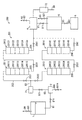
図2は、本発明の第2実施形態に係るアンモニア精製システム150の構成を示す図である。本実施形態のアンモニア精製システム150は、前述のアンモニア精製システム100に類似し、対応する部分については同一の参照符号を付して説明を省略する。アンモニア精製システム150は、吸着ユニット151の構成が、前述の吸着ユニット3の構成と異なること以外は、アンモニア精製システム100と同様である。   FIG. 2 is a diagram showing a configuration of an ammonia purification system 150 according to the second embodiment of the present invention. The ammonia purification system 150 of the present embodiment is similar to the ammonia purification system 100 described above, and corresponding portions are denoted by the same reference numerals and description thereof is omitted. The ammonia purification system 150 is the same as the ammonia purification system 100 except that the configuration of the adsorption unit 151 is different from the configuration of the adsorption unit 3 described above.

吸着ユニット151は、気化器2から導出された気体状のアンモニアに含まれる不純物を吸着除去して精製する。本実施形態では、吸着ユニット151は、第1吸着塔1511、第2吸着塔1512、および第3吸着塔1513を含んで構成される。   The adsorption unit 151 performs purification by adsorbing and removing impurities contained in gaseous ammonia led out from the vaporizer 2. In the present embodiment, the adsorption unit 151 includes a first adsorption tower 1511, a second adsorption tower 1512, and a third adsorption tower 1513.

第1吸着塔1511、第2吸着塔1512および第3吸着塔1513は、前述の第1吸着塔31と同様に構成される。具体的には、第1吸着塔1511は、塔頂部から塔底部に向かって(アンモニアの流れ方向上流側から下流側に向かって)順番に、塔頂吸着層15111、第1中間吸着層15112、第2中間吸着層15113、および塔底吸着層15114が積層された積層構造を有する。   The first adsorption tower 1511, the second adsorption tower 1512, and the third adsorption tower 1513 are configured in the same manner as the first adsorption tower 31 described above. Specifically, the first adsorption tower 1511 has a tower top adsorption layer 15111, a first intermediate adsorption layer 15112, in order from the tower top to the tower bottom (from the upstream to the downstream in the ammonia flow direction). A second intermediate adsorption layer 15113 and a tower bottom adsorption layer 15114 are laminated.

塔頂吸着層15111は、第1吸着剤を含む層であり、第1吸着剤層としての機能を有する。第1吸着剤は、水に対して高い吸着能を有する多孔質吸着剤である。このような第1吸着剤としては、たとえば、活性炭などが挙げられる。   The tower top adsorption layer 15111 is a layer containing a first adsorbent and has a function as a first adsorbent layer. The first adsorbent is a porous adsorbent having a high adsorbability for water. Examples of the first adsorbent include activated carbon.

第1中間吸着層15112は、第2吸着剤を含む層であり、第2吸着剤層としての機能を有する。第2吸着剤は、炭素数5未満の有機化合物(炭化水素、アルコール、エーテルなど)に対して高い吸着能を有する多孔質吸着剤である。このような第2吸着剤としては、たとえば、MS−3A(細孔径3Åの多孔質合成ゼオライト)、MS−4A(細孔径4Åの多孔質合成ゼオライト)、MS−5A(細孔径5Åの多孔質合成ゼオライト)、MS−13X(細孔径9Åの多孔質合成ゼオライト)などの親水性ゼオライト、ハイシリカ型(シリカ/アルミナ比が高い)ゼオライトなどの疎水性ゼオライト、シリカゲルなどが挙げられる。また、第2中間吸着層15113は、第1中間吸着層15112と同様に、第2吸着剤を含む層であり、第2吸着剤層としての機能を有する。ただし、第1中間吸着層15112と第2中間吸着層15113とは、第2吸着剤を含む層であることで同じであるけれども、互いに種類が異なる吸着剤を用いる。   The first intermediate adsorption layer 15112 is a layer containing a second adsorbent and has a function as a second adsorbent layer. The second adsorbent is a porous adsorbent having a high adsorbability for organic compounds having less than 5 carbon atoms (hydrocarbon, alcohol, ether, etc.). Examples of such second adsorbent include MS-3A (porous synthetic zeolite having a pore diameter of 3 mm), MS-4A (porous synthetic zeolite having a pore diameter of 4 mm), and MS-5A (porous having a pore diameter of 5 mm). Synthetic zeolite), hydrophilic zeolite such as MS-13X (porous synthetic zeolite having a pore size of 9 mm), hydrophobic zeolite such as high silica type (high silica / alumina ratio) zeolite, silica gel and the like. Similarly to the first intermediate adsorption layer 15112, the second intermediate adsorption layer 15113 is a layer containing a second adsorbent and has a function as a second adsorbent layer. However, although the first intermediate adsorption layer 15112 and the second intermediate adsorption layer 15113 are the same because they are layers containing the second adsorbent, different types of adsorbents are used.

塔底吸着層15114は、第3吸着剤を含む層であり、第3吸着剤層としての機能を有する。第3吸着剤は、炭素数5以上の有機化合物(炭化水素など)および水に対して高い吸着能を有する多孔質吸着剤である。このような第3吸着剤としては、活性炭、MS−13Xなどが挙げられる。   The tower bottom adsorption layer 15114 is a layer containing a third adsorbent and has a function as a third adsorbent layer. The third adsorbent is a porous adsorbent having high adsorbability for organic compounds having 5 or more carbon atoms (such as hydrocarbons) and water. Examples of such a third adsorbent include activated carbon and MS-13X.

第2吸着塔1512は、塔頂部から塔底部に向かって(アンモニアの流れ方向上流側から下流側に向かって)順番に、塔頂吸着層15121、第1中間吸着層15122、第2中間吸着層15123、および塔底吸着層15124が積層された積層構造を有する。   The second adsorption tower 1512 has a tower top adsorption layer 15121, a first intermediate adsorption layer 15122, and a second intermediate adsorption layer in order from the tower top to the tower bottom (from the upstream to the downstream in the ammonia flow direction). 15123 and a tower bottom adsorbing layer 15124 are stacked.

塔頂吸着層15121は、前述した第1吸着塔31の塔頂吸着層311と同様に構成された、第1吸着剤を含む層であり、第1吸着剤層としての機能を有する。第1中間吸着層15122は、前述した第1吸着塔31の第1中間吸着層312と同様に構成された、第2吸着剤を含む層であり、第2吸着剤層としての機能を有する。第2中間吸着層15123は、前述した第1吸着塔31の第2中間吸着層313と同様に構成された、第2吸着剤を含む層であり、第2吸着剤層としての機能を有する。塔底吸着層15124は、前述した第1吸着塔31の塔底吸着層314と同様に構成された、第3吸着剤を含む層であり、第3吸着剤層としての機能を有する。   The tower top adsorption layer 15121 is a layer containing the first adsorbent, which is configured in the same manner as the tower top adsorption layer 311 of the first adsorption tower 31 described above, and has a function as a first adsorbent layer. The first intermediate adsorption layer 15122 is a layer including the second adsorbent, which is configured in the same manner as the first intermediate adsorption layer 312 of the first adsorption tower 31 described above, and has a function as a second adsorbent layer. The second intermediate adsorption layer 15123 is a layer including the second adsorbent, which is configured in the same manner as the second intermediate adsorption layer 313 of the first adsorption tower 31 described above, and has a function as a second adsorbent layer. The tower bottom adsorption layer 15124 is a layer containing a third adsorbent, which is configured in the same manner as the tower bottom adsorption layer 314 of the first adsorption tower 31 described above, and has a function as a third adsorbent layer.

本実施形態では、気化器2から導出された気体状のアンモニアが流れる第3配管83には、第3配管83から分岐する第15A配管152、第15B配管153および第15C配管154が接続される。   In the present embodiment, the 15A piping 152, the 15B piping 153, and the 15C piping 154 branched from the third piping 83 are connected to the third piping 83 through which gaseous ammonia derived from the vaporizer 2 flows. .

第15A配管152は、第3配管83から分岐して第1吸着塔1511の塔頂部に接続される。この第15A配管152には、第15A配管152における流路を開放または閉鎖する第15Aバルブ1521が設けられている。第15B配管153は、第3配管83から分岐して第2吸着塔1512の塔頂部に接続される。この第15B配管153には、第15B配管153における流路を開放または閉鎖する第15Bバルブ1531が設けられている。第15C配管154は、第3配管83から分岐して第3吸着塔1513の塔頂部に接続される。この第15C配管154には、第15C配管154における流路を開放または閉鎖する第15Cバルブ1541が設けられている。   The 15A pipe 152 branches from the third pipe 83 and is connected to the top of the first adsorption tower 1511. The 15A pipe 152 is provided with a 15A valve 1521 that opens or closes the flow path in the 15A pipe 152. The 15B pipe 153 branches from the third pipe 83 and is connected to the tower top of the second adsorption tower 1512. The 15B pipe 153 is provided with a 15B valve 1531 that opens or closes the flow path in the 15B pipe 153. The 15th C pipe 154 branches from the third pipe 83 and is connected to the top of the third adsorption tower 1513. The 15th C pipe 154 is provided with a 15th C valve 1541 that opens or closes the flow path in the 15th C pipe 154.

また、第1吸着塔1511の塔底部には、第1吸着塔1511から導出された気体状のアンモニアが流れる第15D配管155が接続される。この第15D配管155には、第15D配管155における流路を開放または閉鎖する第15Dバルブ1551が設けられている。第2吸着塔1512の塔底部には、第2吸着塔1512から導出された気体状のアンモニアが流れる第15E配管156が接続される。この第15E配管156には、第15E配管156における流路を開放または閉鎖する第15Eバルブ1561が設けられている。第3吸着塔1513の塔底部には、第3吸着塔1513から導出された気体状のアンモニアが流れる第15F配管157が接続される。この第15F配管157には、第15F配管157における流路を開放または閉鎖する第15Fバルブ1571が設けられている。   A 15D pipe 155 through which gaseous ammonia derived from the first adsorption tower 1511 flows is connected to the bottom of the first adsorption tower 1511. The 15D pipe 155 is provided with a 15D valve 1551 that opens or closes the flow path in the 15D pipe 155. A 15E pipe 156 through which gaseous ammonia derived from the second adsorption tower 1512 flows is connected to the bottom of the second adsorption tower 1512. The 15E pipe 156 is provided with a 15E valve 1561 that opens or closes the flow path in the 15E pipe 156. A 15th F pipe 157 through which gaseous ammonia derived from the third adsorption tower 1513 flows is connected to the bottom of the third adsorption tower 1513. The 15th F pipe 157 is provided with a 15th F valve 1571 for opening or closing the flow path in the 15th F pipe 157.

また、第15D配管155には、第15D配管155から分岐する第15G配管158が接続される。この第15G配管158は、第15D配管155から分岐して第15B配管153に接続され、第1吸着塔1511から導出された気体状のアンモニアを、第2吸着塔1512に導入するための流路となる。第15G配管158には、第15G配管158における流路を開放または閉鎖する第15Gバルブ1581が設けられている。この第15G配管158には、第15G配管158から分岐する第15H配管159が接続される。この第25H配管159は、第15G配管158から分岐して第15C配管154に接続され、第1吸着塔1511から導出された気体状のアンモニアを、第3吸着塔1513に導入するための流路となる。第15H配管159には、第15H配管159における流路を開放または閉鎖する第15Hバルブ1591が設けられている。   In addition, a 15th G pipe 158 branched from the 15D pipe 155 is connected to the 15D pipe 155. The 15G pipe 158 is branched from the 15D pipe 155 and connected to the 15B pipe 153, and a flow path for introducing gaseous ammonia led out from the first adsorption tower 1511 into the second adsorption tower 1512. It becomes. The 15G pipe 158 is provided with a 15G valve 1581 that opens or closes the flow path in the 15G pipe 158. A 15th H pipe 159 branched from the 15th G pipe 158 is connected to the 15th G pipe 158. The 25th H pipe 159 is branched from the 15th G pipe 158 and connected to the 15th C pipe 154, and a flow path for introducing gaseous ammonia derived from the first adsorption tower 1511 to the third adsorption tower 1513. It becomes. The 15th H pipe 159 is provided with a 15th H valve 1591 that opens or closes the flow path in the 15th H pipe 159.

また、第15E配管156には、第15E配管156から分岐する第15I配管160および第15J配管161が接続される。第15I配管160は、第15E配管156から分岐して第15A配管152に接続され、第2吸着塔1512から導出された気体状のアンモニアを、第1吸着塔1511に導入するための流路となる。第15I配管160には、第15I配管160における流路を開放または閉鎖する第15Iバルブ1601が設けられている。第15J配管161は、第15E配管156から分岐して第15C配管154に接続され、第2吸着塔1512から導出された気体状のアンモニアを、第3吸着塔1513に導入するための流路となる。第15J配管161には、第15J配管161における流路を開放または閉鎖する第15Jバルブ1611が設けられている。   In addition, a 15I pipe 160 and a 15J pipe 161 branched from the 15E pipe 156 are connected to the 15E pipe 156. The 15I pipe 160 branches from the 15E pipe 156 and is connected to the 15A pipe 152, and a flow path for introducing gaseous ammonia led out from the second adsorption tower 1512 into the first adsorption tower 1511. Become. The 15I pipe 160 is provided with a 15I valve 1601 that opens or closes the flow path in the 15I pipe 160. The 15J pipe 161 is branched from the 15E pipe 156 and connected to the 15C pipe 154, and a flow path for introducing gaseous ammonia led out from the second adsorption tower 1512 into the third adsorption tower 1513, Become. The 15J pipe 161 is provided with a 15J valve 1611 that opens or closes the flow path in the 15J pipe 161.

また、第15F配管157には、第15F配管157から分岐する第15K配管162が接続される。この第15K配管162は、第15F配管157から分岐して第15A配管152に接続され、第3吸着塔1513から導出された気体状のアンモニアを、第1吸着塔1511に導入するための流路となる。第15K配管162には、第15K配管162における流路を開放または閉鎖する第15Kバルブ1621が設けられている。この第15K配管162には、第15K配管162から分岐する第15L配管163が接続される。この第15L配管163は、第15K配管162から分岐して第15B配管153に接続され、第3吸着塔1513から導出された気体状のアンモニアを、第2吸着塔1512に導入するための流路となる。第15L配管163には、第15L配管163における流路を開放または閉鎖する第15Lバルブ1631が設けられている。   Further, the 15th F pipe 157 is connected to a 15K pipe 162 branched from the 15th F pipe 157. This 15K pipe 162 is branched from the 15th F pipe 157 and connected to the 15A pipe 152, and a flow path for introducing gaseous ammonia derived from the third adsorption tower 1513 into the first adsorption tower 1511. It becomes. The 15th K pipe 162 is provided with a 15th K valve 1621 that opens or closes the flow path in the 15th K pipe 162. A 15th L pipe 163 branched from the 15th K pipe 162 is connected to the 15th K pipe 162. This 15L pipe 163 is branched from the 15K pipe 162 and connected to the 15B pipe 153, and a flow path for introducing gaseous ammonia derived from the third adsorption tower 1513 into the second adsorption tower 1512. It becomes. The 15th L pipe 163 is provided with a 15th L valve 1631 that opens or closes the flow path in the 15th L pipe 163.

また、第15D配管155、第15E配管156および第15F配管157において、気体状のアンモニアの流れ方向下流側端部には、第15M配管164が接続される。この第15M配管164には、第1吸着塔1511、第2吸着塔1512および第3吸着塔1513のいずれか1つの吸着塔から導出された気体状のアンモニアが供給される。そして、第15M配管164には、第15M配管164から分岐してコンデンサ4に接続される第15N配管165が設けられる。   Further, in the 15D pipe 155, the 15E pipe 156 and the 15F pipe 157, the 15M pipe 164 is connected to the downstream end portion in the flow direction of gaseous ammonia. The 15M pipe 164 is supplied with gaseous ammonia derived from any one of the first adsorption tower 1511, the second adsorption tower 1512 and the third adsorption tower 1513. The 15th M pipe 164 is provided with a 15th N pipe 165 branched from the 15th M pipe 164 and connected to the capacitor 4.

以上のように構成されるアンモニア精製システム150では、第1吸着塔1511、第2吸着塔1512および第3吸着塔1513の接続について、以下の6つの接続パターンがある。   In the ammonia purification system 150 configured as described above, there are the following six connection patterns for connecting the first adsorption tower 1511, the second adsorption tower 1512, and the third adsorption tower 1513.

第1の接続パターンは、気化器2から導出された気体状のアンモニアを、第1吸着塔1511、第2吸着塔1512の順に通過させる接続パターンである。第1の接続パターンでは、第15Aバルブ1521、第15Eバルブ1561および第15Gバルブ1581を開放させ、第15Bバルブ1531、第15Cバルブ1541、第15Dバルブ1551、第15Fバルブ1571、第15Hバルブ1591、第15Iバルブ1601、第15Jバルブ1611、第15Kバルブ1621および第15Lバルブ1631を閉鎖させる。   The first connection pattern is a connection pattern that allows gaseous ammonia derived from the vaporizer 2 to pass through the first adsorption tower 1511 and the second adsorption tower 1512 in this order. In the first connection pattern, the 15A valve 1521, the 15E valve 1561 and the 15G valve 1581 are opened, the 15B valve 1531, the 15C valve 1541, the 15D valve 1551, the 15F valve 1571, the 15H valve 1591, The 15I valve 1601, the 15J valve 1611, the 15K valve 1621 and the 15L valve 1631 are closed.

これによって、気化器2から導出された気体状のアンモニアは、第15A配管152を流れて第1吸着塔1511に導入され、第1吸着塔1511から導出された気体状のアンモニアは、第15D配管155および第15G配管158を流過して第2吸着塔1512に導入され、第2吸着塔1512から導出された気体状のアンモニアは、第15E配管156を流過して第15M配管164に供給され、この第15M配管164からコンデンサ4に気体状のアンモニアが導入される。   As a result, gaseous ammonia derived from the vaporizer 2 flows through the 15A piping 152 and is introduced into the first adsorption tower 1511, and gaseous ammonia derived from the first adsorption tower 1511 is converted into the 15D piping. 155 and the 15G pipe 158 are passed through the second adsorption tower 1512 and gaseous ammonia derived from the second adsorption tower 1512 flows through the 15E pipe 156 and is supplied to the 15M pipe 164. Then, gaseous ammonia is introduced into the condenser 4 from the 15th M pipe 164.

このような第1の接続パターンでは、気体状のアンモニアに含まれる不純物を、第1吸着塔1511および第2吸着塔1512で吸着除去することができるので、不純物に対する吸着除去能力を向上することができる。なお、第1の接続パターンでは、第3吸着塔1513における吸着除去動作は実行されないので、この第3吸着塔1513を再生処理することができる。   In such a first connection pattern, impurities contained in gaseous ammonia can be adsorbed and removed by the first adsorption tower 1511 and the second adsorption tower 1512, so that the ability to adsorb and remove impurities can be improved. it can. In the first connection pattern, since the adsorption removal operation in the third adsorption tower 1513 is not executed, the third adsorption tower 1513 can be regenerated.

第2の接続パターンは、気化器2から導出された気体状のアンモニアを、第1吸着塔1511、第3吸着塔1513の順に通過させる接続パターンである。第2の接続パターンでは、第15Aバルブ1521、第15Fバルブ1571および第15Hバルブ1591を開放させ、第15Bバルブ1531、第15Cバルブ1541、第15Dバルブ1551、第15Eバルブ1561、第15Gバルブ1581、第15Iバルブ1601、第15Jバルブ1611、第15Kバルブ1621および第15Lバルブ1631を閉鎖させる。   The second connection pattern is a connection pattern that allows gaseous ammonia derived from the vaporizer 2 to pass through the first adsorption tower 1511 and the third adsorption tower 1513 in this order. In the second connection pattern, the 15A valve 1521, the 15F valve 1571 and the 15H valve 1591 are opened, the 15B valve 1531, the 15C valve 1541, the 15D valve 1551, the 15E valve 1561, the 15G valve 1581, The 15I valve 1601, the 15J valve 1611, the 15K valve 1621 and the 15L valve 1631 are closed.

これによって、気化器2から導出された気体状のアンモニアは、第15A配管152を流れて第1吸着塔1511に導入され、第1吸着塔1511から導出された気体状のアンモニアは、第15D配管155、第15G配管158および第15H配管159を流れて第3吸着塔1513に導入され、第3吸着塔1513から導出された気体状のアンモニアは、第15F配管157を流過して第15M配管164に供給され、この第15M配管164からコンデンサ4に気体状のアンモニアが導入される。   As a result, gaseous ammonia derived from the vaporizer 2 flows through the 15A piping 152 and is introduced into the first adsorption tower 1511, and gaseous ammonia derived from the first adsorption tower 1511 is converted into the 15D piping. 155, the 15G pipe 158 and the 15H pipe 159, are introduced into the third adsorption tower 1513, and the gaseous ammonia led out from the third adsorption tower 1513 flows through the 15th F pipe 157 and the 15M pipe. 164 is supplied, and gaseous ammonia is introduced into the condenser 4 from the 15th M pipe 164.

このような第2の接続パターンでは、気体状のアンモニアに含まれる不純物を、第1吸着塔1511および第3吸着塔1513で吸着除去することができるので、不純物に対する吸着除去能力を向上することができる。なお、第2の接続パターンでは、第2吸着塔1512における吸着除去動作は実行されないので、この第2吸着塔1512を再生処理することができる。   In such a second connection pattern, impurities contained in gaseous ammonia can be adsorbed and removed by the first adsorption tower 1511 and the third adsorption tower 1513, so that the ability to adsorb and remove impurities can be improved. it can. In the second connection pattern, since the adsorption removal operation in the second adsorption tower 1512 is not executed, the second adsorption tower 1512 can be regenerated.

第3の接続パターンは、気化器2から導出された気体状のアンモニアを、第2吸着塔1512、第1吸着塔1511の順に通過させる接続パターンである。第3の接続パターンでは、第15Bバルブ1531、第15Dバルブ1551および第15Iバルブ1601を開放させ、第15Aバルブ1521、第15Cバルブ1541、第15Eバルブ1561、第15Fバルブ1571、第15Gバルブ1581、第15Hバルブ1591、第15Jバルブ1611、第15Kバルブ1621および第15Lバルブ1631を閉鎖させる。   The third connection pattern is a connection pattern that allows gaseous ammonia derived from the vaporizer 2 to pass through the second adsorption tower 1512 and the first adsorption tower 1511 in this order. In the third connection pattern, the 15B valve 1531, the 15D valve 1551, and the 15I valve 1601 are opened, the 15A valve 1521, the 15C valve 1541, the 15E valve 1561, the 15F valve 1571, the 15G valve 1581, The 15th H valve 1591, the 15th J valve 1611, the 15th K valve 1621 and the 15th L valve 1631 are closed.

これによって、気化器2から導出された気体状のアンモニアは、第15B配管153を流れて第2吸着塔1512に導入され、第2吸着塔1512から導出された気体状のアンモニアは、第15E配管156および第15I配管160を流れて第1吸着塔1511に導入され、第1吸着塔1511から導出された気体状のアンモニアは、第15D配管155を流れて第15M配管164に供給され、この第15M配管164からコンデンサ4に気体状のアンモニアが導入される。   Thereby, the gaseous ammonia derived from the vaporizer 2 flows through the 15B pipe 153 and is introduced into the second adsorption tower 1512, and the gaseous ammonia derived from the second adsorption tower 1512 is converted into the 15E pipe. 156 and the 15I piping 160 are introduced into the first adsorption tower 1511 and the gaseous ammonia led out from the first adsorption tower 1511 flows through the 15D piping 155 and is supplied to the 15M piping 164. Gaseous ammonia is introduced into the condenser 4 from the 15M pipe 164.

このような第3の接続パターンでは、気体状のアンモニアに含まれる不純物を、第1吸着塔1511および第2吸着塔1512で吸着除去することができるので、不純物に対する吸着除去能力を向上することができる。なお、第3の接続パターンでは、第3吸着塔1513における吸着除去動作は実行されないので、この第3吸着塔1513を再生処理することができる。   In such a third connection pattern, impurities contained in gaseous ammonia can be adsorbed and removed by the first adsorption tower 1511 and the second adsorption tower 1512, so that the ability to adsorb and remove impurities can be improved. it can. In the third connection pattern, since the adsorption removal operation in the third adsorption tower 1513 is not executed, the third adsorption tower 1513 can be regenerated.

第4の接続パターンは、気化器2から導出された気体状のアンモニアを、第2吸着塔1512、第3吸着塔1513の順に通過させる接続パターンである。第4の接続パターンでは、第15Bバルブ1531、第15Fバルブ1571および第15Jバルブ1611を開放させ、第15Aバルブ1521、第15Cバルブ1541、第15Dバルブ1551、第15Eバルブ1561、第15Gバルブ1581、第15Hバルブ1591、第15Iバルブ1601、第15Kバルブ1621および第15Lバルブ1631を閉鎖させる。   The fourth connection pattern is a connection pattern that allows gaseous ammonia derived from the vaporizer 2 to pass through the second adsorption tower 1512 and the third adsorption tower 1513 in this order. In the fourth connection pattern, the 15B valve 1531, the 15F valve 1571, and the 15J valve 1611 are opened, the 15A valve 1521, the 15C valve 1541, the 15D valve 1551, the 15E valve 1561, the 15G valve 1581, The 15H valve 1591, the 15I valve 1601, the 15K valve 1621 and the 15L valve 1631 are closed.

これによって、気化器2から導出された気体状のアンモニアは、第15B配管153を流れて第2吸着塔1512に導入され、第2吸着塔1512から導出された気体状のアンモニアは、第15E配管156および第15J配管161を流過して第3吸着塔1513に導入され、第3吸着塔1513から導出された気体状のアンモニアは、第15F配管157を流れて第15M配管164に供給され、この第15M配管164からコンデンサ4に気体状のアンモニアが導入される。   Thereby, the gaseous ammonia derived from the vaporizer 2 flows through the 15B pipe 153 and is introduced into the second adsorption tower 1512, and the gaseous ammonia derived from the second adsorption tower 1512 is converted into the 15E pipe. 156 and the 15J pipe 161 are passed through and introduced into the third adsorption tower 1513, and the gaseous ammonia led out from the third adsorption tower 1513 flows through the 15th F pipe 157 and is supplied to the 15M pipe 164. Gaseous ammonia is introduced into the condenser 4 from the 15th M pipe 164.

このような第4の接続パターンでは、気体状のアンモニアに含まれる不純物を、第2吸着塔1512および第3吸着塔1513で吸着除去することができるので、不純物に対する吸着除去能力を向上することができる。なお、第4の接続パターンでは、第1吸着塔1511における吸着除去動作は実行されないので、この第1吸着塔1511を再生処理することができる。   In such a fourth connection pattern, impurities contained in gaseous ammonia can be adsorbed and removed by the second adsorption tower 1512 and the third adsorption tower 1513, so that the ability to adsorb and remove impurities can be improved. it can. In the fourth connection pattern, since the adsorption removal operation in the first adsorption tower 1511 is not executed, the first adsorption tower 1511 can be regenerated.

第5の接続パターンは、気化器2から導出された気体状のアンモニアを、第3吸着塔1513、第1吸着塔1511の順に通過させる接続パターンである。第5の接続パターンでは、第15Cバルブ1541、第15Dバルブ1551および第15Kバルブ1621を開放させ、第15Aバルブ1521、第15Bバルブ1531、第15Eバルブ1561、第15Fバルブ1571、第15Gバルブ1581、第15Hバルブ1591、第15Iバルブ1601、第15Jバルブ1611および第15Lバルブ1631を閉鎖させる。   The fifth connection pattern is a connection pattern that allows gaseous ammonia derived from the vaporizer 2 to pass through the third adsorption tower 1513 and the first adsorption tower 1511 in this order. In the fifth connection pattern, the 15C valve 1541, the 15D valve 1551, and the 15K valve 1621 are opened, the 15A valve 1521, the 15B valve 1531, the 15E valve 1561, the 15F valve 1571, the 15G valve 1581, The 15th H valve 1591, the 15th I valve 1601, the 15th J valve 1611 and the 15th L valve 1631 are closed.

これによって、気化器2から導出された気体状のアンモニアは、第15C配管154を流れて第3吸着塔1513に導入され、第3吸着塔1513から導出された気体状のアンモニアは、第15F配管157および第15K配管162を流れて第1吸着塔1511に導入され、第1吸着塔1511から導出された気体状のアンモニアは、第15D配管155を流過して第15M配管164に供給され、この第15M配管164からコンデンサ4に気体状のアンモニアが導入される。   Thereby, the gaseous ammonia derived from the vaporizer 2 flows through the 15C pipe 154 and is introduced into the third adsorption tower 1513, and the gaseous ammonia derived from the third adsorption tower 1513 is converted into the 15th F pipe. 157 and the 15K pipe 162 are introduced into the first adsorption tower 1511 and gaseous ammonia derived from the first adsorption tower 1511 flows through the 15D pipe 155 and is supplied to the 15M pipe 164. Gaseous ammonia is introduced into the condenser 4 from the 15th M pipe 164.

このような第5の接続パターンでは、気体状のアンモニアに含まれる不純物を、第1吸着塔1511および第3吸着塔1513で吸着除去することができるので、不純物に対する吸着除去能力を向上することができる。なお、第5の接続パターンでは、第2吸着塔1512における吸着除去動作は実行されないので、この第2吸着塔1512を再生処理することができる。   In such a fifth connection pattern, impurities contained in gaseous ammonia can be adsorbed and removed by the first adsorption tower 1511 and the third adsorption tower 1513, so that the ability to adsorb and remove impurities can be improved. it can. In the fifth connection pattern, since the adsorption removal operation in the second adsorption tower 1512 is not executed, the second adsorption tower 1512 can be regenerated.

第6の接続パターンは、気化器2から導出された気体状のアンモニアを、第3吸着塔1513、第2吸着塔1512の順に通過させる接続パターンである。第6の接続パターンでは、第15Cバルブ1541、第15Eバルブ1561および第15Lバルブ1631を開放させ、第15Aバルブ1521、第15Bバルブ1531、第15Dバルブ1551、第15Fバルブ1571、第15Gバルブ1581、第15Hバルブ1591、第15Iバルブ1601、第15Jバルブ1611および第15Kバルブ1621を閉鎖させる。   The sixth connection pattern is a connection pattern that allows gaseous ammonia derived from the vaporizer 2 to pass through the third adsorption tower 1513 and the second adsorption tower 1512 in this order. In the sixth connection pattern, the 15C valve 1541, the 15E valve 1561 and the 15L valve 1631 are opened, and the 15A valve 1521, the 15B valve 1531, the 15D valve 1551, the 15F valve 1571, the 15G valve 1581, The 15th H valve 1591, the 15th I valve 1601, the 15th J valve 1611 and the 15th K valve 1621 are closed.

これによって、気化器2から導出された気体状のアンモニアは、第15C配管154を流れて第3吸着塔1513に導入され、第3吸着塔1513から導出された気体状のアンモニアは、第15F配管157、第15K配管162および第15L配管163を流れて第2吸着塔1512に導入され、第2吸着塔1512から導出された気体状のアンモニアは、第15E配管156を流過して第15M配管164に供給され、この第15M配管164からコンデンサ4に気体状のアンモニアが導入される。   Thereby, the gaseous ammonia derived from the vaporizer 2 flows through the 15C pipe 154 and is introduced into the third adsorption tower 1513, and the gaseous ammonia derived from the third adsorption tower 1513 is converted into the 15th F pipe. 157, the 15K pipe 162 and the 15L pipe 163 flow into the second adsorption tower 1512 and the gaseous ammonia led out from the second adsorption tower 1512 flows through the 15E pipe 156 and the 15M pipe. 164 is supplied, and gaseous ammonia is introduced into the condenser 4 from the 15th M pipe 164.

このような第6の接続パターンでは、気体状のアンモニアに含まれる不純物を、第2吸着塔1512および第3吸着塔1513で吸着除去することができるので、不純物に対する吸着除去能力を向上することができる。なお、第6の接続パターンでは、第1吸着塔1511における吸着除去動作は実行されないので、この第1吸着塔1511を再生処理することができる。   In such a sixth connection pattern, impurities contained in gaseous ammonia can be adsorbed and removed by the second adsorption tower 1512 and the third adsorption tower 1513, so that the ability to adsorb and remove impurities can be improved. it can. Note that, in the sixth connection pattern, the adsorption removal operation in the first adsorption tower 1511 is not executed, so that the first adsorption tower 1511 can be regenerated.

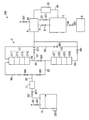
図3は、本発明の第3実施形態に係るアンモニア精製システム200の構成を示す図である。本実施形態のアンモニア精製システム200は、前述のアンモニア精製システム100に類似し、対応する部分については同一の参照符号を付して説明を省略する。アンモニア精製システム200は、吸着ユニット201の構成が、前述の吸着ユニット3の構成と異なること以外は、アンモニア精製システム100と同様である。   FIG. 3 is a diagram showing a configuration of an ammonia purification system 200 according to the third embodiment of the present invention. The ammonia purification system 200 of the present embodiment is similar to the ammonia purification system 100 described above, and corresponding portions are denoted by the same reference numerals and description thereof is omitted. The ammonia purification system 200 is the same as the ammonia purification system 100 except that the configuration of the adsorption unit 201 is different from the configuration of the adsorption unit 3 described above.

吸着ユニット201は、気化器2から導出された気体状のアンモニアに含まれる不純物を吸着除去して精製する。本実施形態では、吸着ユニット201は、第1吸着塔2011、第2吸着塔2012、第3吸着塔2013および第4吸着塔2014を含んで構成される。   The adsorption unit 201 adsorbs and removes impurities contained in gaseous ammonia derived from the vaporizer 2 for purification. In the present embodiment, the adsorption unit 201 includes a first adsorption tower 2011, a second adsorption tower 2012, a third adsorption tower 2013, and a fourth adsorption tower 2014.

第1吸着塔2011および第3吸着塔2013は、第20配管202に並列に接続されている。第20配管202には、第20配管202における流路を開放または閉鎖する第21バルブ2021および第22バルブ2022が設けられている。第20配管202において、第21バルブ2021は、第1吸着塔2011の上流側(すなわち、第1吸着塔2011の塔頂部側)に配置され、第22バルブ2022は、第3吸着塔2013の上流側(すなわち、第3吸着塔2013の塔頂部側)に配置される。気化器2から導出された気体状のアンモニアの第1吸着塔2011への供給時には、第21バルブ2021が開放され、第22バルブ2022が閉鎖されて、気化器2から第1吸着塔2011に向けて第20配管202内を気体状のアンモニアが流れる。また、気化器2から導出された気体状のアンモニアの第3吸着塔2013への供給時には、第22バルブ2022が開放され、第21バルブ2021が閉鎖されて、気化器2から第3吸着塔2013に向けて第20配管202内を気体状のアンモニアが流れる。   The first adsorption tower 2011 and the third adsorption tower 2013 are connected to the 20th pipe 202 in parallel. The twentieth pipe 202 is provided with a twenty-first valve 2021 and a twenty-second valve 2022 that open or close the flow path in the twentieth pipe 202. In the twentieth piping 202, the 21st valve 2021 is disposed on the upstream side of the first adsorption tower 2011 (that is, the tower top side of the first adsorption tower 2011), and the 22nd valve 2022 is located upstream of the third adsorption tower 2013. It arrange | positions at the side (namely, tower top side of the 3rd adsorption tower 2013). When supplying gaseous ammonia derived from the vaporizer 2 to the first adsorption tower 2011, the 21st valve 2021 is opened, the 22nd valve 2022 is closed, and the vaporizer 2 is directed to the first adsorption tower 2011. Then, gaseous ammonia flows in the 20th pipe 202. In addition, when supplying gaseous ammonia derived from the vaporizer 2 to the third adsorption tower 2013, the 22nd valve 2022 is opened, the 21st valve 2021 is closed, and the third adsorption tower 2013 from the vaporizer 2 is closed. Gaseous ammonia flows in the 20th pipe 202 toward.

このように、吸着ユニット201が、並列接続される第1吸着塔2011および第3吸着塔2013を有することによって、気化器2から導出された気体状のアンモニアを、並列接続される第1吸着塔2011および第3吸着塔2013に対して、それぞれ区別した状態で導入することができるので、たとえば、第1吸着塔2011で吸着除去している間に、使用済みの第3吸着塔2013で再度吸着除去動作が可能なように、使用済みの第3吸着塔2013を再生処理することができる。   As described above, the adsorption unit 201 includes the first adsorption tower 2011 and the third adsorption tower 2013 connected in parallel, so that the gaseous ammonia derived from the vaporizer 2 can be connected in parallel to the first adsorption tower. 2011 and the third adsorption tower 2013 can be introduced in a state of being distinguished from each other, for example, while the first adsorption tower 2011 is adsorbing and removing, the used third adsorption tower 2013 is again adsorbed. The used third adsorption tower 2013 can be regenerated so that the removal operation can be performed.

第2吸着塔2012は、第21配管203を介して第1吸着塔2011と直列に接続されている。すなわち、第21配管203において、一端部は第1吸着塔2011の塔底部に接続され、他端部は第2吸着塔2012の塔頂部に接続されている。これによって、気化器2から導出されて、第1吸着塔2011に導入された気体状のアンモニアは、第23バルブ2031が開放された状態で、第21配管203を流れて第2吸着塔2012に導入される。このように、吸着ユニット201が、直列接続される第1吸着塔2011および第2吸着塔2012を有することによって、気化器2から導出された気体状のアンモニアに含まれる不純物を、第1吸着塔2011および第2吸着塔2012で吸着除去することができるので、不純物に対する吸着除去能力を向上することができる。   The second adsorption tower 2012 is connected in series with the first adsorption tower 2011 via the 21st pipe 203. That is, in the 21st pipe 203, one end is connected to the tower bottom of the first adsorption tower 2011 and the other end is connected to the tower top of the second adsorption tower 2012. Thereby, gaseous ammonia led out from the vaporizer 2 and introduced into the first adsorption tower 2011 flows into the second adsorption tower 2012 through the 21st pipe 203 with the 23rd valve 2031 opened. be introduced. As described above, the adsorption unit 201 includes the first adsorption tower 2011 and the second adsorption tower 2012 connected in series, so that impurities contained in the gaseous ammonia derived from the vaporizer 2 can be removed from the first adsorption tower. Since it can be adsorbed and removed by 2011 and the second adsorption tower 2012, the ability to adsorb and remove impurities can be improved.

第2吸着塔2012から導出された気体状のアンモニアは、第24バルブ2041が開放された状態で、第22配管204を流れて、コンデンサ4に供給される。   Gaseous ammonia derived from the second adsorption tower 2012 flows through the 22nd pipe 204 and is supplied to the capacitor 4 with the 24th valve 2041 opened.

第4吸着塔2014は、第23配管205を介して第3吸着塔2013と直列に接続されている。すなわち、第23配管205において、一端部は第3吸着塔2013の塔底部に接続され、他端部は第4吸着塔2014の塔頂部に接続されている。これによって、気化器2から導出されて、第3吸着塔2013に導入された気体状のアンモニアは、第25バルブ2051が開放された状態で、第23配管205を流れて第4吸着塔2014に導入される。このように、吸着ユニット201が、直列接続される第3吸着塔2013および第4吸着塔2014を有することによって、気化器2から導出された気体状のアンモニアに含まれる不純物を、第3吸着塔2013および第4吸着塔2014で吸着除去することができるので、不純物に対する吸着除去能力を向上することができる。   The fourth adsorption tower 2014 is connected in series with the third adsorption tower 2013 via the 23rd pipe 205. That is, in the 23rd pipe 205, one end is connected to the tower bottom of the third adsorption tower 2013 and the other end is connected to the tower top of the fourth adsorption tower 2014. As a result, the gaseous ammonia led out from the vaporizer 2 and introduced into the third adsorption tower 2013 flows through the 23rd pipe 205 with the 25th valve 2051 opened to the fourth adsorption tower 2014. be introduced. Thus, the adsorption unit 201 has the third adsorption tower 2013 and the fourth adsorption tower 2014 connected in series, so that impurities contained in the gaseous ammonia derived from the vaporizer 2 can be removed from the third adsorption tower. Since it can be adsorbed and removed by 2013 and the fourth adsorption tower 2014, the ability to adsorb and remove impurities can be improved.

第4吸着塔2014から導出された気体状のアンモニアは、第26バルブ2061が開放された状態で、第24配管206を流れて、コンデンサ4に供給される。   The gaseous ammonia led out from the fourth adsorption tower 2014 flows through the 24th pipe 206 with the 26th valve 2061 being opened, and is supplied to the capacitor 4.

アンモニア精製システム200の吸着ユニット201における第1吸着塔2011は、塔頂部から塔底部に向かって(アンモニアの流れ方向上流側から下流側に向かって)順番に、塔頂吸着層20111、第1中間吸着層20112、第2中間吸着層20113、第3中間吸着層20114、および塔底吸着層20115が積層された積層構造を有する。   The first adsorption tower 2011 in the adsorption unit 201 of the ammonia purification system 200 is arranged in order from the tower top to the tower bottom (from the upstream to the downstream in the ammonia flow direction). The adsorbing layer 20112, the second intermediate adsorbing layer 20113, the third intermediate adsorbing layer 20114, and the tower bottom adsorbing layer 20115 are stacked.

塔頂吸着層20111は、前述した吸着ユニット3における第1吸着塔31の塔頂吸着層311と同様に構成された、第1吸着剤を含む層であり、第1吸着剤層としての機能を有する。第1中間吸着層20112は、前述した第1吸着塔31の第1中間吸着層312と同様に構成された、第2吸着剤を含む層であり、第2吸着剤層としての機能を有する。第2中間吸着層20113は、前述した第1吸着塔31の第2中間吸着層313と同様に構成された、第2吸着剤を含む層であり、第2吸着剤層としての機能を有する。第3中間吸着層20114は、前述した第1吸着塔31の第1中間吸着層312および第2中間吸着層313と同様に構成された、第2吸着剤を含む層であり、第2吸着剤層としての機能を有する。ただし、第1中間吸着層20112と、第2中間吸着層20113と、第3中間吸着層20114とは、第2吸着剤を含む層であることで同じであるけれども、互いに種類が異なる吸着剤を用いる。塔底吸着層20115は、前述した第1吸着塔31の塔底吸着層314と同様に構成された、第3吸着剤を含む層であり、第3吸着剤層としての機能を有する。   The tower top adsorption layer 20111 is a layer containing the first adsorbent, which is configured in the same manner as the tower top adsorption layer 311 of the first adsorption tower 31 in the adsorption unit 3 described above, and has a function as the first adsorbent layer. Have. The 1st intermediate adsorption layer 20112 is a layer containing the 2nd adsorbent comprised similarly to the 1st intermediate adsorption layer 312 of the 1st adsorption tower 31 mentioned above, and has a function as a 2nd adsorbent layer. The second intermediate adsorption layer 20113 is a layer including the second adsorbent, which is configured in the same manner as the second intermediate adsorption layer 313 of the first adsorption tower 31 described above, and has a function as a second adsorbent layer. The third intermediate adsorption layer 20104 is a layer including the second adsorbent, which is configured in the same manner as the first intermediate adsorption layer 312 and the second intermediate adsorption layer 313 of the first adsorption tower 31 described above. It functions as a layer. However, the first intermediate adsorption layer 20112, the second intermediate adsorption layer 20113, and the third intermediate adsorption layer 20114 are the same because they are layers containing the second adsorbent, but different types of adsorbents are used. Use. The tower bottom adsorption layer 20115 is a layer containing the third adsorbent, which is configured in the same manner as the tower bottom adsorption layer 314 of the first adsorption tower 31 described above, and has a function as a third adsorbent layer.

第1吸着塔2011における積層構造について、具体例を挙げて説明する。第1の具体例では、塔頂吸着層20111は、第1吸着剤として活性炭(GG、クラレケミカル株式会社製)を含む層であり、第1中間吸着層20112は、第2吸着剤としてシリカゲル(シルビードN、水澤化学工業株式会社製)を含む層であり、第2中間吸着層20113は、第2吸着剤として親水性ゼオライト(MS−3A、東ソー株式会社製)を含む層であり、第3中間吸着層20114は、第2吸着剤として疎水性ゼオライト(HSZ−300、シリカ/アルミナ比=10、東ソー株式会社製)を含む層であり、塔底吸着層20115は、第3吸着剤として活性炭(GG、クラレケミカル株式会社製)を含む層である。   The laminated structure in the first adsorption tower 2011 will be described with a specific example. In the first specific example, the tower top adsorption layer 20111 is a layer containing activated carbon (GG, manufactured by Kuraray Chemical Co., Ltd.) as the first adsorbent, and the first intermediate adsorption layer 20112 is silica gel ( The second intermediate adsorption layer 20113 is a layer containing hydrophilic zeolite (MS-3A, manufactured by Tosoh Corporation) as the second adsorbent, and the third intermediate adsorption layer 20113. The intermediate adsorption layer 20114 is a layer containing hydrophobic zeolite (HSZ-300, silica / alumina ratio = 10, manufactured by Tosoh Corporation) as the second adsorbent, and the tower bottom adsorption layer 20115 is activated carbon as the third adsorbent. It is a layer containing (GG, manufactured by Kuraray Chemical Co., Ltd.).

第2の具体例では、塔頂吸着層20111は、第1吸着剤として活性炭(GG、クラレケミカル株式会社製)を含む層であり、第1中間吸着層20112は、第2吸着剤として親水性ゼオライト(MS−3A、東ソー株式会社製)を含む層であり、第2中間吸着層20113は、第2吸着剤としてシリカゲル(シルビードN、水澤化学工業株式会社製)を含む層であり、第3中間吸着層20114は、第2吸着剤として疎水性ゼオライト(HiSiv、ユニオン昭和株式会社製)を含む層であり、塔底吸着層20115は、第3吸着剤としてMS−13X(東ソー株式会社製)を含む層である。   In the second specific example, the tower top adsorption layer 20111 is a layer containing activated carbon (GG, manufactured by Kuraray Chemical Co., Ltd.) as the first adsorbent, and the first intermediate adsorption layer 20112 is hydrophilic as the second adsorbent. It is a layer containing zeolite (MS-3A, manufactured by Tosoh Corporation), and the second intermediate adsorption layer 20113 is a layer containing silica gel (Sylbeed N, manufactured by Mizusawa Chemical Co., Ltd.) as the second adsorbent. The intermediate adsorption layer 20114 is a layer containing hydrophobic zeolite (HiSiv, manufactured by Union Showa Co., Ltd.) as the second adsorbent, and the tower bottom adsorption layer 20115 is MS-13X (produced by Tosoh Corporation) as the third adsorbent. It is a layer containing.

以上のように構成された本実施形態のアンモニア精製システム200では、水、炭素数5未満の有機化合物、炭素数5以上の有機化合物に対する吸着能がそれぞれ異なる吸着剤層が積層された、第1吸着塔2011、第2吸着塔2012、第3吸着塔2013、および第4吸着塔2014によって、粗アンモニアに含有される不純物を吸着除去するので、粗アンモニアに含有される不純物(主に水および有機化合物)を効率よく吸着除去することができる。そして、コンデンサ4は、第2吸着塔2012または第4吸着塔2014から導出されたアンモニアを分縮して気相成分と液相成分とに分離するので、水素、窒素、酸素、アルゴン、一酸化炭素、二酸化炭素などの、揮発性の高い不純物を、気相成分として分離除去し、液相成分として精製された液体状のアンモニアを得ることができる。そのため、本実施形態のアンモニア精製システム200では、従来技術のように還流を伴う蒸留を行うことなく、簡単化された方法でアンモニアを精製することができるとともに、エネルギの消費を抑制してアンモニアを効率的に精製することができる。   In the ammonia purification system 200 of the present embodiment configured as described above, the adsorbent layers having different adsorption capacities for water, organic compounds having less than 5 carbon atoms, and organic compounds having 5 or more carbon atoms are stacked. Since the adsorption tower 2011, the second adsorption tower 2012, the third adsorption tower 2013, and the fourth adsorption tower 2014 adsorb and remove impurities contained in the crude ammonia, impurities contained in the crude ammonia (mainly water and organic Compound) can be efficiently adsorbed and removed. And since the capacitor | condenser 4 fractionates and isolate | separates the ammonia derived | led-out from the 2nd adsorption tower 2012 or the 4th adsorption tower 2014 into a gaseous-phase component and a liquid phase component, it is hydrogen, nitrogen, oxygen, argon, monoxide Highly volatile impurities such as carbon and carbon dioxide can be separated and removed as a gas phase component to obtain liquid ammonia purified as a liquid phase component. Therefore, in the ammonia purification system 200 of the present embodiment, ammonia can be purified by a simplified method without performing distillation with reflux as in the prior art, and energy consumption is suppressed and ammonia is reduced. It can be purified efficiently.

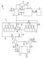
図4は、本発明の第4実施形態に係るアンモニア精製システム300の構成を示す図である。本実施形態のアンモニア精製システム300は、前述のアンモニア精製システム100に類似し、対応する部分については同一の参照符号を付して説明を省略する。アンモニア精製システム300は、原料貯留タンク1Aの構成が、前述の原料貯留タンク1の構成と異なること以外は、アンモニア精製システム100と同様である。   FIG. 4 is a diagram showing a configuration of an ammonia purification system 300 according to the fourth embodiment of the present invention. The ammonia purification system 300 of the present embodiment is similar to the ammonia purification system 100 described above, and corresponding portions are denoted by the same reference numerals and description thereof is omitted. The ammonia purification system 300 is the same as the ammonia purification system 100 except that the configuration of the raw material storage tank 1A is different from the configuration of the raw material storage tank 1 described above.

アンモニア精製システム300に備えられる原料貯留タンク1Aは、粗アンモニアを液体状のアンモニアとして貯留し、所定の温度および圧力になるように制御されている。原料貯留タンク1Aは、円柱状の内部空間を有し、その内部空間に液体状の粗アンモニアを貯留した状態で、原料貯留タンク1Aの上部には気相が形成され、下部には液相が形成されている。   The raw material storage tank 1A provided in the ammonia purification system 300 stores crude ammonia as liquid ammonia and is controlled so as to have a predetermined temperature and pressure. The raw material storage tank 1A has a cylindrical internal space, and in the state where liquid crude ammonia is stored in the internal space, a gas phase is formed in the upper part of the raw material storage tank 1A, and a liquid phase is formed in the lower part. Is formed.

本実施形態では、原料貯留タンク1Aは、貯留された粗アンモニアを、吸着ユニット3に向けて導出する。なお、アンモニア精製システム300には、前述の気化器2は備えられていない。原料貯留タンク1Aから吸着ユニット3に粗アンモニアが導出される際には、揮発性の低い不純物(たとえば、水分、炭素数6を超える炭化水素など)の多くが液相に残されて、原料貯留タンク1Aに形成される気相から気体状の粗アンモニアとして導出される。原料貯留タンク1Aには、原料貯留タンク1A内に貯留される液体状の粗アンモニアの一部を気化させ、気相におけるアンモニア濃度を上昇させるために、液体状の粗アンモニアを加熱する加熱装置302が設けられている。   In the present embodiment, the raw material storage tank 1 </ b> A derives the stored crude ammonia toward the adsorption unit 3. The ammonia purification system 300 is not provided with the above-described vaporizer 2. When crude ammonia is derived from the raw material storage tank 1A to the adsorption unit 3, most of low-volatile impurities (for example, moisture, hydrocarbons having more than 6 carbon atoms, etc.) are left in the liquid phase, and raw material storage is performed. It is derived as gaseous crude ammonia from the gas phase formed in the tank 1A. In the raw material storage tank 1A, a heating device 302 that heats the liquid crude ammonia in order to vaporize part of the liquid crude ammonia stored in the raw material storage tank 1A and increase the ammonia concentration in the gas phase. Is provided.

原料貯留タンク1Aの上部(気相が形成された部分)には、気体状アンモニア導出配管301が接続されている。気体状アンモニア導出配管301の、原料貯留タンク1Aと接続される側とは反対側の端部は、流量調整器71に接続されている。また、気体状アンモニア導出配管301には、気体状アンモニア導出配管301における流路を開放または閉鎖する開閉バルブ3011が設けられている。   A gaseous ammonia outlet pipe 301 is connected to the upper part of the raw material storage tank 1A (the part where the gas phase is formed). The end of the gaseous ammonia outlet pipe 301 opposite to the side connected to the raw material storage tank 1 </ b> A is connected to the flow rate regulator 71. The gaseous ammonia outlet pipe 301 is provided with an opening / closing valve 3011 that opens or closes the flow path in the gaseous ammonia outlet pipe 301.

原料貯留タンク1Aに貯留された粗アンモニアは、開閉バルブ3011が開放された状態で、原料貯留タンク1Aに形成される気相から気体状の粗アンモニアとして導出される。このようにして原料貯留タンク1Aから導出された気体状の粗アンモニアは、気体状アンモニア導出配管301を流れて、流量調整器71に供給される。そして、気体状の粗アンモニアは、流量調整器71によって流量が調整されて、第1吸着塔31および第2吸着塔32を有する吸着ユニット3に供給されることになる。吸着ユニット3に供給された気体状の粗アンモニアは、第1吸着塔31および第2吸着塔32によって不純物が吸着除去されて精製される。さらに、第1吸着塔31および第2吸着塔32において精製された気体状のアンモニアは、コンデンサ4において分縮されて揮発性の高い不純物が分離除去される。   The crude ammonia stored in the raw material storage tank 1A is derived as gaseous crude ammonia from the gas phase formed in the raw material storage tank 1A with the opening / closing valve 3011 being opened. The gaseous crude ammonia derived from the raw material storage tank 1 </ b> A in this way flows through the gaseous ammonia outlet piping 301 and is supplied to the flow rate regulator 71. The gaseous crude ammonia is supplied to the adsorption unit 3 having the first adsorption tower 31 and the second adsorption tower 32 with the flow rate adjusted by the flow regulator 71. The gaseous crude ammonia supplied to the adsorption unit 3 is purified by removing impurities by the first adsorption tower 31 and the second adsorption tower 32. Further, gaseous ammonia purified in the first adsorption tower 31 and the second adsorption tower 32 is fractionated in the condenser 4 to separate and remove highly volatile impurities.

以上のように構成された本実施形態のアンモニア精製システム300では、水、炭素数5未満の有機化合物、炭素数5以上の有機化合物に対する吸着能がそれぞれ異なる吸着剤層が積層された、第1吸着塔31および第2吸着塔32によって、気体状の粗アンモニアに含有される不純物を吸着除去するので、粗アンモニアに含有される不純物(主に水および有機化合物)を効率よく吸着除去することができる。そして、コンデンサ4は、第1吸着塔31または第2吸着塔32から導出されたアンモニアを分縮して気相成分と液相成分とに分離するので、水素、窒素、酸素、アルゴン、一酸化炭素、二酸化炭素などの、揮発性の高い不純物を、気相成分として分離除去し、液相成分として精製された液体状のアンモニアを得ることができる。そのため、本実施形態のアンモニア精製システム300では、従来技術のように還流を伴う蒸留を行うことなく、簡単化された方法でアンモニアを精製することができるとともに、エネルギの消費を抑制してアンモニアを効率的に精製することができる。   In the ammonia purification system 300 of the present embodiment configured as described above, the adsorbent layers having different adsorption capacities for water, organic compounds having less than 5 carbon atoms, and organic compounds having 5 or more carbon atoms are stacked. Since the adsorption tower 31 and the second adsorption tower 32 adsorb and remove impurities contained in the crude gaseous ammonia, it is possible to efficiently remove the impurities (mainly water and organic compounds) contained in the crude ammonia. it can. And since the capacitor | condenser 4 carries out partial condensation of the ammonia derived | led-out from the 1st adsorption tower 31 or the 2nd adsorption tower 32, and isolate | separates into a gaseous-phase component and a liquid phase component, hydrogen, nitrogen, oxygen, argon, monoxide Highly volatile impurities such as carbon and carbon dioxide can be separated and removed as a gas phase component to obtain liquid ammonia purified as a liquid phase component. Therefore, in the ammonia purification system 300 of the present embodiment, ammonia can be purified by a simplified method without performing distillation with reflux as in the prior art, and energy consumption is suppressed and ammonia is reduced. It can be purified efficiently.

図5は、本発明の第5実施形態に係るアンモニア精製システム400の構成を示す図である。本実施形態のアンモニア精製システム400は、前述のアンモニア精製システム100に類似し、対応する部分については同一の参照符号を付して説明を省略する。アンモニア精製システム400は、原料貯留タンク1Bの構成が、前述の原料貯留タンク1の構成と異なること以外は、アンモニア精製システム100と同様である。   FIG. 5 is a diagram showing a configuration of an ammonia purification system 400 according to the fifth embodiment of the present invention. The ammonia purification system 400 of the present embodiment is similar to the ammonia purification system 100 described above, and corresponding portions are denoted by the same reference numerals and description thereof is omitted. The ammonia purification system 400 is the same as the ammonia purification system 100 except that the configuration of the raw material storage tank 1B is different from the configuration of the raw material storage tank 1 described above.

アンモニア精製システム400に備えられる原料貯留タンク1Bは、粗アンモニアを液体状のアンモニアとして貯留し、所定の温度および圧力になるように制御されている。原料貯留タンク1Bは、円柱状の内部空間を有し、その内部空間に液体状の粗アンモニアを貯留した状態で、原料貯留タンク1Bの上部には気相が形成され、下部には液相が形成されている。また、原料貯留タンク1Bには、原料貯留タンク1B内に貯留される液体状の粗アンモニアの一部を気化させ、気相におけるアンモニア濃度を上昇させるために、液体状の粗アンモニアを加熱する加熱装置403が設けられている。   The raw material storage tank 1B provided in the ammonia purification system 400 stores crude ammonia as liquid ammonia and is controlled so as to have a predetermined temperature and pressure. The raw material storage tank 1B has a cylindrical internal space, and in the state where liquid crude ammonia is stored in the internal space, a gas phase is formed in the upper part of the raw material storage tank 1B, and a liquid phase is formed in the lower part. Is formed. The raw material storage tank 1B is heated to heat the liquid crude ammonia in order to vaporize part of the liquid crude ammonia stored in the raw material storage tank 1B and increase the ammonia concentration in the gas phase. A device 403 is provided.

本実施形態では、原料貯留タンク1Bは、貯留された粗アンモニアを、気相および液相のいずれの相からも導出可能に構成されている。   In the present embodiment, the raw material storage tank 1B is configured to be able to derive the stored crude ammonia from either the gas phase or the liquid phase.

原料貯留タンク1B内における液体状の粗アンモニアの充填量(貯留量)によって、原料貯留タンク1Bに形成される気相の不純物(特に揮発性の高い不純物)濃度が異なる。原料貯留タンク1B内における液体状の粗アンモニアの充填量が多いほど、原料貯留タンク1Bに形成される気相において、揮発性の高い不純物濃度が高くなる。また、原料貯留タンク1B内における液体状の粗アンモニアの充填量が少ないほど、原料貯留タンク1Bに形成される液相において、揮発性の低い不純物(たとえば、水、炭素数が大きい有機化合物)の濃度が高くなる。すなわち、原料貯留タンク1Bに形成される液相から液体状の粗アンモニアを導出する場合、原料貯留タンク1B内における液体状の粗アンモニアの充填量が減少するにつれて、揮発性の低い不純物濃度が高い粗アンモニアが原料貯留タンク1Bの液相から導出されることになる。   The concentration of gas phase impurities (particularly highly volatile impurities) formed in the raw material storage tank 1B varies depending on the amount of liquid crude ammonia charged (reserved amount) in the raw material storage tank 1B. The higher the filling amount of liquid crude ammonia in the raw material storage tank 1B, the higher the volatile impurity concentration in the gas phase formed in the raw material storage tank 1B. Further, the smaller the filling amount of the liquid crude ammonia in the raw material storage tank 1B, the lower the volatility of impurities (for example, water, organic compounds having a large number of carbon atoms) in the liquid phase formed in the raw material storage tank 1B. The concentration becomes high. That is, when liquid crude ammonia is derived from the liquid phase formed in the raw material storage tank 1B, the concentration of impurities with low volatility increases as the amount of liquid crude ammonia in the raw material storage tank 1B decreases. Crude ammonia is derived from the liquid phase of the raw material storage tank 1B.

したがって、本実施形態のアンモニア精製システム400は、原料貯留タンク1B内における液体状の粗アンモニアの充填量に応じて、粗アンモニアの導出状態(気相および液相のいずれの相から粗アンモニアを導出させるかの導出動作の制御)を切替えるように構成されている。アンモニア精製システム400は、原料貯留タンク1B内における、内部空間の容積に対する液相の容積の比である容積比を算出し、該容積比が予め定める閾値以上である場合に、原料貯留タンク1Bに形成される液相から液体状の粗アンモニアを導出するように構成され、前記閾値未満である場合に、原料貯留タンク1Bに形成される気相から気体状の粗アンモニアを導出するように構成されている。   Therefore, the ammonia purification system 400 of the present embodiment derives crude ammonia from either the gas phase or the liquid phase according to the amount of liquid crude ammonia charged in the raw material storage tank 1B. The control of the derivation operation to be performed) is switched. The ammonia purification system 400 calculates a volume ratio that is a ratio of the volume of the liquid phase to the volume of the internal space in the raw material storage tank 1B, and when the volume ratio is equal to or greater than a predetermined threshold, It is configured to derive liquid crude ammonia from the liquid phase to be formed, and is configured to derive gaseous crude ammonia from the gas phase formed in the raw material storage tank 1B when it is less than the threshold. ing.

具体的には、アンモニア精製システム400では、原料貯留タンク1B内に貯留される液体状の粗アンモニアの、内部空間における液面高さが検出される。内部空間の大きさの寸法が予めわかっていれば、液面高さを用いて前記容積比を算出することができる。特に、底面に平行な断面が一定の内部空間では、内部空間の高さに対する液面高さの比が、前記容積比と同じになるので、容積比の算出が容易となる。   Specifically, in the ammonia purification system 400, the liquid level height in the internal space of the liquid crude ammonia stored in the raw material storage tank 1B is detected. If the dimension of the size of the internal space is known in advance, the volume ratio can be calculated using the liquid level height. In particular, in an internal space having a constant cross-section parallel to the bottom surface, the ratio of the liquid level to the height of the internal space is the same as the volume ratio, so the volume ratio can be easily calculated.

本実施形態では、原料貯留タンク1Bに形成される内部空間は、円柱状であるので、円形の底面に平行な断面が一定の内部空間である。したがって、内部空間の高さに対する液面高さの比が、前記容積比と同じになる。そこで、アンモニア精製システム400は、原料貯留タンク1Bの内部空間の高さの値と、液面高さの値を用いて、内部空間の高さに対する液面高さの比((液面高さ/内部空間の高さ)、以下「高さ比」という)を、前記容積比に相当する値として算出する。   In this embodiment, since the internal space formed in the raw material storage tank 1B is a columnar shape, the cross section parallel to the circular bottom surface is a constant internal space. Therefore, the ratio of the liquid level to the height of the internal space is the same as the volume ratio. Therefore, the ammonia purification system 400 uses the value of the height of the internal space of the raw material storage tank 1B and the value of the liquid level, and the ratio of the liquid level to the height of the internal space ((the liquid level height / Height of the internal space), hereinafter referred to as “height ratio”) is calculated as a value corresponding to the volume ratio.

さらに、アンモニア精製システム400では、前記高さ比が予め定める閾値(本実施形態では、閾値=1/2)以上である場合に、原料貯留タンク1Bに形成される液相から液体状の粗アンモニアを導出するように、原料貯留タンク1Bの粗アンモニアの導出動作が制御される。また、アンモニア精製システム400では、前記高さ比が予め定める閾値未満である場合に、原料貯留タンク1Bに形成される気相から気体状の粗アンモニアを導出するように、原料貯留タンク1Bの粗アンモニアの導出動作が制御される。   Furthermore, in the ammonia purification system 400, when the height ratio is equal to or higher than a predetermined threshold value (threshold value = 1/2 in the present embodiment), liquid crude ammonia is formed from the liquid phase formed in the raw material storage tank 1B. So as to derive the crude ammonia in the raw material storage tank 1B. Further, in the ammonia purification system 400, when the height ratio is less than a predetermined threshold value, the raw material storage tank 1B is rough so that gaseous crude ammonia is derived from the gas phase formed in the raw material storage tank 1B. The ammonia deriving operation is controlled.

換言すると、本実施形態のアンモニア精製システム400は、原料貯留タンク1B内において、原料貯留タンク1Bの高さの1/2(前記閾値に相当)以上の高さ位置まで、液体状の粗アンモニアが充填されていることが検出された場合には、原料貯留タンク1Bに形成される液相から液体状の粗アンモニアが導出されるように構成されている。また、アンモニア精製システム400は、原料貯留タンク1B内において、原料貯留タンク1Bの高さの1/2(前記閾値に相当)未満の高さ位置まで、液体状の粗アンモニアが充填されていることが検出された場合には、原料貯留タンク1Bに形成される気相から気体状の粗アンモニアが導出されるように構成されている。   In other words, the ammonia refining system 400 of the present embodiment is configured so that the liquid crude ammonia is in the raw material storage tank 1B up to a height position equal to or higher than ½ of the height of the raw material storage tank 1B (corresponding to the threshold value). When it is detected that the fuel is filled, liquid crude ammonia is derived from the liquid phase formed in the raw material storage tank 1B. In addition, the ammonia purification system 400 is filled with liquid crude ammonia up to a height position less than ½ of the height of the raw material storage tank 1B (corresponding to the threshold value) in the raw material storage tank 1B. Is detected, gaseous gaseous ammonia is derived from the gas phase formed in the raw material storage tank 1B.

このように、原料貯留タンク1B内における液体状の粗アンモニアの充填量に応じて、粗アンモニアの導出状態を切替えるように構成することによって、不純物濃度のばらつきが少ない状態で、粗アンモニアを原料貯留タンク1Bから導出することができる。これによって、最終的に精製されるアンモニアの純度に大きなばらつきが発生するのを防止することができる。   In this way, the crude ammonia can be stored in the raw material storage state with little variation in impurity concentration by switching the derivation state of the crude ammonia in accordance with the amount of liquid crude ammonia charged in the raw material storage tank 1B. It can be derived from the tank 1B. As a result, it is possible to prevent large variations in the purity of the finally purified ammonia.

原料貯留タンク1Bの下部(液相が形成された部分)には、液体状アンモニア導出配管401が接続されている。液体状アンモニア導出配管401の、原料貯留タンク1Bと接続される側とは反対側の端部は、気化器2に接続されている。また、液体状アンモニア導出配管401には、液体状アンモニア導出配管401における流路を開放または閉鎖する開閉バルブ4011が設けられている。原料貯留タンク1Bに貯留された粗アンモニアは、開閉バルブ4011が開放された状態で、原料貯留タンク1Bに形成される液相から液体状の粗アンモニアとして導出される。このようにして原料貯留タンク1Bから導出された液体状の粗アンモニアは、液体状アンモニア導出配管401を流れて、気化器2に供給される。原料貯留タンク1Bから導出された液体状の粗アンモニアは、気化器2によって気化されて、気体状のアンモニアとして流量調整器71に供給される。このようにして気化器2によって気化された気体状のアンモニアは、流量調整器71によって流量が調整されて、第1吸着塔31および第2吸着塔32を有する吸着ユニット3に供給されることになる。   A liquid ammonia outlet pipe 401 is connected to the lower part (part where the liquid phase is formed) of the raw material storage tank 1B. The end of the liquid ammonia outlet pipe 401 opposite to the side connected to the raw material storage tank 1 </ b> B is connected to the vaporizer 2. The liquid ammonia outlet pipe 401 is provided with an opening / closing valve 4011 that opens or closes the flow path in the liquid ammonia outlet pipe 401. The crude ammonia stored in the raw material storage tank 1B is derived as liquid crude ammonia from the liquid phase formed in the raw material storage tank 1B with the open / close valve 4011 being opened. The liquid crude ammonia derived from the raw material storage tank 1B in this way flows through the liquid ammonia outlet piping 401 and is supplied to the vaporizer 2. The liquid crude ammonia derived from the raw material storage tank 1B is vaporized by the vaporizer 2 and supplied to the flow regulator 71 as gaseous ammonia. In this way, the gaseous ammonia vaporized by the vaporizer 2 is supplied to the adsorption unit 3 having the first adsorption tower 31 and the second adsorption tower 32 after the flow rate is adjusted by the flow rate regulator 71. Become.

また、原料貯留タンク1Bの上部(気相が形成された部分)には、気体状アンモニア導出配管402が接続されている。気体状アンモニア導出配管402の、原料貯留タンク1Bと接続される側とは反対側の端部は、流量調整器71に接続されている。また、気体状アンモニア導出配管402には、気体状アンモニア導出配管402における流路を開放または閉鎖する開閉バルブ4021が設けられている。   In addition, a gaseous ammonia outlet pipe 402 is connected to the upper part of the raw material storage tank 1B (the part where the gas phase is formed). The end of the gaseous ammonia outlet pipe 402 opposite to the side connected to the raw material storage tank 1 </ b> B is connected to the flow rate regulator 71. The gaseous ammonia lead-out pipe 402 is provided with an open / close valve 4021 that opens or closes the flow path in the gaseous ammonia lead-out pipe 402.

原料貯留タンク1Bに貯留された粗アンモニアは、開閉バルブ4021が開放された状態で、原料貯留タンク1Bに形成される気相から気体状の粗アンモニアとして導出される。このようにして原料貯留タンク1Bから導出された気体状の粗アンモニアは、気体状アンモニア導出配管402を流れて、流量調整器71に供給される。そして、気体状の粗アンモニアは、流量調整器71によって流量が調整されて、第1吸着塔31および第2吸着塔32を有する吸着ユニット3に供給されることになる。   The crude ammonia stored in the raw material storage tank 1B is derived as gaseous crude ammonia from the gas phase formed in the raw material storage tank 1B with the open / close valve 4021 being opened. The gaseous crude ammonia derived from the raw material storage tank 1B in this way flows through the gaseous ammonia outlet piping 402 and is supplied to the flow rate regulator 71. The gaseous crude ammonia is supplied to the adsorption unit 3 having the first adsorption tower 31 and the second adsorption tower 32 with the flow rate adjusted by the flow regulator 71.

本実施形態のアンモニア精製システム400において、吸着ユニット3に供給された気体状のアンモニアは、第1吸着塔31および第2吸着塔32によって不純物が吸着除去されて精製される。さらに、第1吸着塔31および第2吸着塔32において精製された気体状のアンモニアは、コンデンサ4において分縮されて揮発性の高い不純物が分離除去される。   In the ammonia purification system 400 of the present embodiment, gaseous ammonia supplied to the adsorption unit 3 is purified by removing impurities by the first adsorption tower 31 and the second adsorption tower 32. Further, gaseous ammonia purified in the first adsorption tower 31 and the second adsorption tower 32 is fractionated in the condenser 4 to separate and remove highly volatile impurities.

以上のように構成された本実施形態のアンモニア精製システム400では、水、炭素数5未満の有機化合物、炭素数5以上の有機化合物に対する吸着能がそれぞれ異なる吸着剤層が積層された、第1吸着塔31および第2吸着塔32によって、気体状の粗アンモニアに含有される不純物を吸着除去するので、粗アンモニアに含有される不純物(主に水および有機化合物)を効率よく吸着除去することができる。そして、コンデンサ4は、第1吸着塔31または第2吸着塔32から導出されたアンモニアを分縮して気相成分と液相成分とに分離するので、水素、窒素、酸素、アルゴン、一酸化炭素、二酸化炭素などの、揮発性の高い不純物を、気相成分として分離除去し、液相成分として精製された液体状のアンモニアを得ることができる。そのため、本実施形態のアンモニア精製システム400では、従来技術のように還流を伴う蒸留を行うことなく、簡単化された方法でアンモニアを精製することができるとともに、エネルギの消費を抑制してアンモニアを効率的に精製することができる。   In the ammonia purification system 400 of the present embodiment configured as described above, the adsorbent layers having different adsorption capacities for water, organic compounds having less than 5 carbon atoms, and organic compounds having 5 or more carbon atoms are stacked. Since the adsorption tower 31 and the second adsorption tower 32 adsorb and remove impurities contained in the crude gaseous ammonia, it is possible to efficiently remove the impurities (mainly water and organic compounds) contained in the crude ammonia. it can. And since the capacitor | condenser 4 carries out partial condensation of the ammonia derived | led-out from the 1st adsorption tower 31 or the 2nd adsorption tower 32, and isolate | separates into a gaseous-phase component and a liquid phase component, hydrogen, nitrogen, oxygen, argon, monoxide Highly volatile impurities such as carbon and carbon dioxide can be separated and removed as a gas phase component to obtain liquid ammonia purified as a liquid phase component. Therefore, in the ammonia purification system 400 of the present embodiment, ammonia can be purified by a simplified method without performing distillation with reflux as in the prior art, and energy consumption is suppressed and ammonia is reduced. It can be purified efficiently.

1,1A,1B 原料貯留タンク
2 気化器
3,151,201 吸着ユニット
4 コンデンサ
5 回収タンク
6 充填装置
31,1511,2011 第1吸着塔
32,1512,2012 第2吸着塔
100,150,200,300,400 アンモニア精製システム
1513,2013 第3吸着塔
2014 第4吸着塔
311,321,15111,15121,15131,20111,20121,20131,20141 塔頂吸着層
312,322,15112,15122,15132,20112,20122,20132,20142 第1中間吸着層
313,323,15113,15123,15133,20113,20123,20133,20143 第2中間吸着層
314,324,15114,15124,15134,20115,20125,20135,20145 塔底吸着層
20114,20124,20134,20144 第3中間吸着層
1, 1A, 1B Raw material storage tank 2 Vaporizer 3, 151, 201 Adsorption unit 4 Capacitor 5 Recovery tank 6 Filling device 31, 1511, 2011 First adsorption tower 32, 1512, 2012 Second adsorption tower 100, 150, 200, 300,400 Ammonia purification system 1513, 2013 3rd adsorption tower 2014 4th adsorption tower 311, 321, 15111, 15121, 15131, 20111, 20121, 20131, 201141 Tower top adsorbing layer 312, 322, 15112, 15122, 15132, 20112 , 20122, 20132, 20142 1st intermediate adsorption layer 313,323,15113,15123,15133,2013,20123,20133,20143 2nd intermediate adsorption layer 314,324,15114,15124,1 5134, 2011, 20125, 20135, 20145 Column bottom adsorption layer 20134, 20124, 20134, 20144 Third intermediate adsorption layer

Claims (5)

不純物が含有される粗アンモニアを精製するアンモニア精製システムにおいて、
粗アンモニアを貯留し、その貯留された粗アンモニアを導出する貯留手段と、
前記貯留手段から導出された粗アンモニアに含有される不純物を、活性炭、親水性ゼオライト、疎水性ゼオライト、シリカゲル、および活性アルミナから選ばれた吸着剤によって吸着除去して精製し、精製されたアンモニアを導出する吸着手段であって、
第1吸着剤を含む第1吸着剤層と、
前記第1吸着剤と種類が異なる第2吸着剤を含む複数の第2吸着剤層と、
前記第2吸着剤と種類が異なる第3吸着剤を含む第3吸着剤層とが、粗アンモニアの流れ方向に積層された吸着部を、1または複数有する吸着手段と、
前記吸着手段から導出された、精製されたアンモニアを分縮して気相成分と液相成分とに分離することで、揮発性の高い不純物を気相成分として分離除去し、液相成分として精製された液体状のアンモニアを得る分縮手段と、を備えることを特徴とするアンモニア精製システム。
In an ammonia purification system for purifying crude ammonia containing impurities,
Storage means for storing crude ammonia and deriving the stored crude ammonia;
Impurities contained in the crude ammonia derived from the storage means are purified by adsorbing and removing with an adsorbent selected from activated carbon, hydrophilic zeolite, hydrophobic zeolite, silica gel and activated alumina. A suction means for deriving,
A first adsorbent layer comprising a first adsorbent;
A plurality of second adsorbent layers including a second adsorbent of a type different from the first adsorbent;
A third adsorbent layer containing a third adsorbent of a type different from the second adsorbent, and an adsorbing means having one or a plurality of adsorbing portions laminated in the flow direction of the crude ammonia;
By separating the purified ammonia derived from the adsorption means into a gas phase component and a liquid phase component, the highly volatile impurities are separated and removed as a gas phase component and purified as a liquid phase component. An ammonia refining system comprising: a contraction means for obtaining the liquid ammonia.
前記貯留手段から導出された液体状の粗アンモニアの一部を気化し、気体状のアンモニアを導出する気化手段をさらに備え、
前記吸着手段は、前記気化手段から導出された気体状のアンモニアに含有される不純物を、前記吸着部によって吸着除去することを特徴とする請求項1に記載のアンモニア精製システム。
Vaporization means for evaporating a part of the liquid crude ammonia derived from the storage means and deriving gaseous ammonia;
The ammonia purification system according to claim 1, wherein the adsorption unit adsorbs and removes impurities contained in gaseous ammonia derived from the vaporization unit by the adsorption unit.
前記第1吸着剤は、水に対して高い吸着能を有する吸着剤であり、
前記第2吸着剤は、炭素数5未満の有機化合物に対して高い吸着能を有する吸着剤であり、
前記第3吸着剤は、炭素数5以上の有機化合物および水に対して高い吸着能を有する吸着剤であることを特徴とする請求項1または2に記載のアンモニア精製システム。
The first adsorbent is an adsorbent having a high adsorbability for water,
The second adsorbent is an adsorbent having a high adsorbing ability for an organic compound having less than 5 carbon atoms,
3. The ammonia purification system according to claim 1, wherein the third adsorbent is an adsorbent having high adsorbability for an organic compound having 5 or more carbon atoms and water.
前記吸着部は、粗アンモニアの流れ方向上流側から下流側に向けて、前記第1吸着剤層、前記複数の第2吸着剤層、および前記第3吸着剤層がこの順番に積層されていることを特徴とする請求項1〜3のいずれか1つに記載のアンモニア精製システム。   In the adsorbing portion, the first adsorbent layer, the plurality of second adsorbent layers, and the third adsorbent layer are laminated in this order from the upstream side to the downstream side in the flow direction of the crude ammonia. The ammonia purification system according to any one of claims 1 to 3. 前記吸着手段は、前記吸着部を複数有し、
複数の吸着部は、直列または並列に接続されていることを特徴とする請求項1〜4のいずれか1つに記載のアンモニア精製システム。
The adsorption means has a plurality of the adsorption portions,
The ammonia purification system according to any one of claims 1 to 4, wherein the plurality of adsorption units are connected in series or in parallel.
JP2012139879A 2012-06-21 2012-06-21 Ammonia purification system Pending JP2014005156A (en)

Priority Applications (5)

Application Number Priority Date Filing Date Title
JP2012139879A JP2014005156A (en) 2012-06-21 2012-06-21 Ammonia purification system
KR1020137014966A KR20140025317A (en) 2012-06-21 2012-12-19 Ammonia purification system
CN201280004087.9A CN103635427A (en) 2012-06-21 2012-12-19 Ammonia purification system
PCT/JP2012/082960 WO2013190731A1 (en) 2012-06-21 2012-12-19 Ammonia purification system
TW101150685A TW201400415A (en) 2012-06-21 2012-12-27 Ammonia purification system

Applications Claiming Priority (1)

Application Number Priority Date Filing Date Title
JP2012139879A JP2014005156A (en) 2012-06-21 2012-06-21 Ammonia purification system

Publications (1)

Publication Number Publication Date
JP2014005156A true JP2014005156A (en) 2014-01-16

Family

ID=49768347

Family Applications (1)

Application Number Title Priority Date Filing Date
JP2012139879A Pending JP2014005156A (en) 2012-06-21 2012-06-21 Ammonia purification system

Country Status (5)

Country Link
JP (1) JP2014005156A (en)
KR (1) KR20140025317A (en)
CN (1) CN103635427A (en)
TW (1) TW201400415A (en)
WO (1) WO2013190731A1 (en)

Cited By (1)

* Cited by examiner, † Cited by third party
Publication number Priority date Publication date Assignee Title
CN106673013A (en) * 2016-11-17 2017-05-17 天津大学 Technology for retrefining defective liquefied ammonia during oil refining waste water production and system thereof

Families Citing this family (3)

* Cited by examiner, † Cited by third party
Publication number Priority date Publication date Assignee Title
CN109790020A (en) * 2016-09-26 2019-05-21 住友精化株式会社 The refining methd and hydrogen of hydrogen or helium or the refining plant of helium
CN106310870A (en) * 2016-11-15 2017-01-11 苏州金宏气体股份有限公司 Device for gradually adsorbing and purifying ammonia gas and method for utilizing device to purify ammonia gas
IT202100018806A1 (en) * 2021-07-15 2023-01-15 Erica S R L LIQUID ADSORPTION PROCESS

Family Cites Families (7)

* Cited by examiner, † Cited by third party
Publication number Priority date Publication date Assignee Title
DD159259A3 (en) * 1979-10-16 1983-03-02 Wolfgang Renker PROCESS FOR THE PRODUCTION OF HIGH-PURITY AMMONIA
US4881953A (en) * 1988-09-15 1989-11-21 Union Carbide Corporation Prevention of membrane degradation
US6065306A (en) * 1998-05-19 2000-05-23 The Boc Group, Inc. Method and apparatus for purifying ammonia
JP2000275971A (en) * 1999-03-25 2000-10-06 Toshiba Corp Image recorder and organic solvent filter
JP4605705B2 (en) * 2005-01-31 2011-01-05 日本エア・リキード株式会社 Ammonia purification system and purification method
US7906665B2 (en) * 2007-10-30 2011-03-15 Iowa State University Research Foundation, Inc. Solid catalyst system for biodiesel production
JP5636261B2 (en) * 2010-11-02 2014-12-03 住友精化株式会社 Ammonia purification system

Cited By (1)

* Cited by examiner, † Cited by third party
Publication number Priority date Publication date Assignee Title
CN106673013A (en) * 2016-11-17 2017-05-17 天津大学 Technology for retrefining defective liquefied ammonia during oil refining waste water production and system thereof

Also Published As

Publication number Publication date
TW201400415A (en) 2014-01-01
CN103635427A (en) 2014-03-12
WO2013190731A1 (en) 2013-12-27
KR20140025317A (en) 2014-03-04

Similar Documents

Publication Publication Date Title
WO2013190732A1 (en) Ammonia purification system
JP4605705B2 (en) Ammonia purification system and purification method
JP5738900B2 (en) Ammonia purification system and ammonia purification method
JP6181312B2 (en) Isopropyl alcohol purification method
JP5822299B2 (en) Propane purification method and purification system
WO2013190731A1 (en) Ammonia purification system
KR20120047756A (en) System for purifying ammonia
JP2012214325A (en) Ammonia purifying system and method for purifying ammonia
JP2016531130A (en) Isopropyl alcohol purification method
JP2016528280A (en) Isopropyl alcohol purification method
JP5815968B2 (en) Ammonia purification system and ammonia purification method
KR100881763B1 (en) The Refining method of Ammonia and apparatus thereof
JP2012153545A (en) Ammonia purification system and ammonia purification method
WO2016121622A1 (en) Process for producing propane, and propane production device
WO2012132559A1 (en) Method for purifying ammonia and ammonia purification system
JP2016188154A (en) Method for purifying ammonia