JP2013544131A - Catheter apparatus having a multi-electrode array for renal neuromodulation and related systems and methods - Google Patents
Catheter apparatus having a multi-electrode array for renal neuromodulation and related systems and methods Download PDFInfo
- Publication number
- JP2013544131A JP2013544131A JP2013536750A JP2013536750A JP2013544131A JP 2013544131 A JP2013544131 A JP 2013544131A JP 2013536750 A JP2013536750 A JP 2013536750A JP 2013536750 A JP2013536750 A JP 2013536750A JP 2013544131 A JP2013544131 A JP 2013544131A
- Authority
- JP
- Japan
- Prior art keywords
- treatment
- support structure
- region
- helical
- energy delivery
- Prior art date
- Legal status (The legal status is an assumption and is not a legal conclusion. Google has not performed a legal analysis and makes no representation as to the accuracy of the status listed.)
- Pending
Links
- JFKJCNJZKBIFGO-UHFFFAOYSA-N C=CC1N=CC1 Chemical compound C=CC1N=CC1 JFKJCNJZKBIFGO-UHFFFAOYSA-N 0.000 description 1
Images


Classifications
-
- A—HUMAN NECESSITIES
- A61—MEDICAL OR VETERINARY SCIENCE; HYGIENE
- A61B—DIAGNOSIS; SURGERY; IDENTIFICATION
- A61B18/00—Surgical instruments, devices or methods for transferring non-mechanical forms of energy to or from the body
- A61B18/04—Surgical instruments, devices or methods for transferring non-mechanical forms of energy to or from the body by heating
- A61B18/12—Surgical instruments, devices or methods for transferring non-mechanical forms of energy to or from the body by heating by passing a current through the tissue to be heated, e.g. high-frequency current
- A61B18/14—Probes or electrodes therefor
- A61B18/1492—Probes or electrodes therefor having a flexible, catheter-like structure, e.g. for heart ablation
-
- A—HUMAN NECESSITIES
- A61—MEDICAL OR VETERINARY SCIENCE; HYGIENE
- A61B—DIAGNOSIS; SURGERY; IDENTIFICATION
- A61B18/00—Surgical instruments, devices or methods for transferring non-mechanical forms of energy to or from the body
- A61B18/04—Surgical instruments, devices or methods for transferring non-mechanical forms of energy to or from the body by heating
- A61B18/12—Surgical instruments, devices or methods for transferring non-mechanical forms of energy to or from the body by heating by passing a current through the tissue to be heated, e.g. high-frequency current
- A61B18/14—Probes or electrodes therefor
-
- A—HUMAN NECESSITIES
- A61—MEDICAL OR VETERINARY SCIENCE; HYGIENE
- A61L—METHODS OR APPARATUS FOR STERILISING MATERIALS OR OBJECTS IN GENERAL; DISINFECTION, STERILISATION OR DEODORISATION OF AIR; CHEMICAL ASPECTS OF BANDAGES, DRESSINGS, ABSORBENT PADS OR SURGICAL ARTICLES; MATERIALS FOR BANDAGES, DRESSINGS, ABSORBENT PADS OR SURGICAL ARTICLES
- A61L29/00—Materials for catheters, medical tubing, cannulae, or endoscopes or for coating catheters
- A61L29/04—Macromolecular materials
-
- A—HUMAN NECESSITIES
- A61—MEDICAL OR VETERINARY SCIENCE; HYGIENE
- A61M—DEVICES FOR INTRODUCING MEDIA INTO, OR ONTO, THE BODY; DEVICES FOR TRANSDUCING BODY MEDIA OR FOR TAKING MEDIA FROM THE BODY; DEVICES FOR PRODUCING OR ENDING SLEEP OR STUPOR
- A61M25/00—Catheters; Hollow probes
- A61M25/0067—Catheters; Hollow probes characterised by the distal end, e.g. tips
- A61M25/0074—Dynamic characteristics of the catheter tip, e.g. openable, closable, expandable or deformable
-
- A—HUMAN NECESSITIES
- A61—MEDICAL OR VETERINARY SCIENCE; HYGIENE
- A61M—DEVICES FOR INTRODUCING MEDIA INTO, OR ONTO, THE BODY; DEVICES FOR TRANSDUCING BODY MEDIA OR FOR TAKING MEDIA FROM THE BODY; DEVICES FOR PRODUCING OR ENDING SLEEP OR STUPOR
- A61M25/00—Catheters; Hollow probes
- A61M25/01—Introducing, guiding, advancing, emplacing or holding catheters
- A61M25/0105—Steering means as part of the catheter or advancing means; Markers for positioning
- A61M25/0133—Tip steering devices
- A61M25/0138—Tip steering devices having flexible regions as a result of weakened outer material, e.g. slots, slits, cuts, joints or coils
-
- A—HUMAN NECESSITIES
- A61—MEDICAL OR VETERINARY SCIENCE; HYGIENE
- A61M—DEVICES FOR INTRODUCING MEDIA INTO, OR ONTO, THE BODY; DEVICES FOR TRANSDUCING BODY MEDIA OR FOR TAKING MEDIA FROM THE BODY; DEVICES FOR PRODUCING OR ENDING SLEEP OR STUPOR
- A61M25/00—Catheters; Hollow probes
- A61M25/01—Introducing, guiding, advancing, emplacing or holding catheters
- A61M25/0105—Steering means as part of the catheter or advancing means; Markers for positioning
- A61M25/0133—Tip steering devices
- A61M25/0147—Tip steering devices with movable mechanical means, e.g. pull wires
-
- A—HUMAN NECESSITIES
- A61—MEDICAL OR VETERINARY SCIENCE; HYGIENE
- A61B—DIAGNOSIS; SURGERY; IDENTIFICATION
- A61B18/00—Surgical instruments, devices or methods for transferring non-mechanical forms of energy to or from the body
- A61B2018/00005—Cooling or heating of the probe or tissue immediately surrounding the probe
- A61B2018/00011—Cooling or heating of the probe or tissue immediately surrounding the probe with fluids
- A61B2018/00023—Cooling or heating of the probe or tissue immediately surrounding the probe with fluids closed, i.e. without wound contact by the fluid
-
- A—HUMAN NECESSITIES
- A61—MEDICAL OR VETERINARY SCIENCE; HYGIENE
- A61B—DIAGNOSIS; SURGERY; IDENTIFICATION
- A61B18/00—Surgical instruments, devices or methods for transferring non-mechanical forms of energy to or from the body
- A61B2018/00315—Surgical instruments, devices or methods for transferring non-mechanical forms of energy to or from the body for treatment of particular body parts
- A61B2018/00345—Vascular system
- A61B2018/00404—Blood vessels other than those in or around the heart
-
- A—HUMAN NECESSITIES
- A61—MEDICAL OR VETERINARY SCIENCE; HYGIENE
- A61B—DIAGNOSIS; SURGERY; IDENTIFICATION
- A61B18/00—Surgical instruments, devices or methods for transferring non-mechanical forms of energy to or from the body
- A61B2018/00315—Surgical instruments, devices or methods for transferring non-mechanical forms of energy to or from the body for treatment of particular body parts
- A61B2018/00434—Neural system
-
- A—HUMAN NECESSITIES
- A61—MEDICAL OR VETERINARY SCIENCE; HYGIENE
- A61B—DIAGNOSIS; SURGERY; IDENTIFICATION
- A61B18/00—Surgical instruments, devices or methods for transferring non-mechanical forms of energy to or from the body
- A61B2018/00315—Surgical instruments, devices or methods for transferring non-mechanical forms of energy to or from the body for treatment of particular body parts
- A61B2018/00505—Urinary tract
- A61B2018/00511—Kidney
-
- A—HUMAN NECESSITIES
- A61—MEDICAL OR VETERINARY SCIENCE; HYGIENE
- A61B—DIAGNOSIS; SURGERY; IDENTIFICATION
- A61B18/00—Surgical instruments, devices or methods for transferring non-mechanical forms of energy to or from the body
- A61B2018/00571—Surgical instruments, devices or methods for transferring non-mechanical forms of energy to or from the body for achieving a particular surgical effect
- A61B2018/00577—Ablation
-
- A—HUMAN NECESSITIES
- A61—MEDICAL OR VETERINARY SCIENCE; HYGIENE
- A61B—DIAGNOSIS; SURGERY; IDENTIFICATION
- A61B18/00—Surgical instruments, devices or methods for transferring non-mechanical forms of energy to or from the body
- A61B2018/00571—Surgical instruments, devices or methods for transferring non-mechanical forms of energy to or from the body for achieving a particular surgical effect
- A61B2018/00595—Cauterization
-
- A—HUMAN NECESSITIES
- A61—MEDICAL OR VETERINARY SCIENCE; HYGIENE
- A61B—DIAGNOSIS; SURGERY; IDENTIFICATION
- A61B18/00—Surgical instruments, devices or methods for transferring non-mechanical forms of energy to or from the body
- A61B18/04—Surgical instruments, devices or methods for transferring non-mechanical forms of energy to or from the body by heating
- A61B18/12—Surgical instruments, devices or methods for transferring non-mechanical forms of energy to or from the body by heating by passing a current through the tissue to be heated, e.g. high-frequency current
- A61B18/14—Probes or electrodes therefor
- A61B2018/1405—Electrodes having a specific shape
- A61B2018/1435—Spiral
-
- A—HUMAN NECESSITIES
- A61—MEDICAL OR VETERINARY SCIENCE; HYGIENE
- A61B—DIAGNOSIS; SURGERY; IDENTIFICATION
- A61B18/00—Surgical instruments, devices or methods for transferring non-mechanical forms of energy to or from the body
- A61B18/04—Surgical instruments, devices or methods for transferring non-mechanical forms of energy to or from the body by heating
- A61B18/12—Surgical instruments, devices or methods for transferring non-mechanical forms of energy to or from the body by heating by passing a current through the tissue to be heated, e.g. high-frequency current
- A61B18/14—Probes or electrodes therefor
- A61B2018/1467—Probes or electrodes therefor using more than two electrodes on a single probe
-
- A—HUMAN NECESSITIES
- A61—MEDICAL OR VETERINARY SCIENCE; HYGIENE
- A61M—DEVICES FOR INTRODUCING MEDIA INTO, OR ONTO, THE BODY; DEVICES FOR TRANSDUCING BODY MEDIA OR FOR TAKING MEDIA FROM THE BODY; DEVICES FOR PRODUCING OR ENDING SLEEP OR STUPOR
- A61M25/00—Catheters; Hollow probes
- A61M25/0021—Catheters; Hollow probes characterised by the form of the tubing
- A61M25/0041—Catheters; Hollow probes characterised by the form of the tubing pre-formed, e.g. specially adapted to fit with the anatomy of body channels
-
- A—HUMAN NECESSITIES
- A61—MEDICAL OR VETERINARY SCIENCE; HYGIENE
- A61M—DEVICES FOR INTRODUCING MEDIA INTO, OR ONTO, THE BODY; DEVICES FOR TRANSDUCING BODY MEDIA OR FOR TAKING MEDIA FROM THE BODY; DEVICES FOR PRODUCING OR ENDING SLEEP OR STUPOR
- A61M25/00—Catheters; Hollow probes
- A61M25/01—Introducing, guiding, advancing, emplacing or holding catheters
- A61M25/0105—Steering means as part of the catheter or advancing means; Markers for positioning
- A61M25/0133—Tip steering devices
Abstract
血管内アクセスにより腎ニューロモジュレーションを実現するためのカテーテル装置、システム、および方法が、本明細書において開示される。例えば本発明のテクノロジーの一態様は、腎臓血管に送達されるように構成されたマルチ電極アレイを有する処置デバイスを対象とする。該アレイは、送達または低プロファイル状態(例えば、概ね直線形状)と配備状態(例えば、放射状に展開された概ね螺旋形状)の間で選択的に変換可能である。マルチ電極アレイは、該アレイが配備(例えば、螺旋)状態にある時に、電極またはエネルギー送達要素が腎臓血管の内壁に接触するようなサイズまたは形状になっている。電極またはエネルギー送達要素は、熱および/または電気エネルギーを直接的および/または間接的に適用して、腎機能に寄与する神経線維、または神経線維に供給もしくは灌流する血管構造を加熱する、または別の方法では電気的にモジュレートするように構成されている。
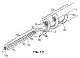
【選択図】図6DDisclosed herein are catheter devices, systems, and methods for achieving renal neuromodulation with intravascular access. For example, one aspect of the technology of the present invention is directed to a treatment device having a multi-electrode array configured to be delivered to a renal vessel. The array can be selectively converted between a delivery or low profile state (eg, a generally linear shape) and a deployed state (eg, a generally helical shape deployed radially). The multi-electrode array is sized or shaped such that the electrode or energy delivery element contacts the inner wall of the kidney vessel when the array is in a deployed (eg, spiral) state. The electrode or energy delivery element applies heat and / or electrical energy directly and / or indirectly to heat nerve fibers that contribute to renal function, or vascular structures that supply or perfuse nerve fibers, or otherwise This method is configured to be electrically modulated.
[Selection] Figure 6D
Description
関連出願の相互参照
本願は、以下の係属出願の利益を主張するものである:
(a)2010年10月25日出願の米国特許仮出願第61/406,531号;
(b)2010年10月26日出願の米国特許仮出願第61/406,960号;
(c)2011年1月28日出願の米国特許仮出願第61/572,290号;
(d)2011年8月25日出願の米国特許仮出願第61/528,001号;
(e)2011年8月26日出願の米国特許仮出願第61/528,086号;
(f)2011年8月26日出願の米国特許仮出願第61/528,091号;
(g)2011年8月26日出願の米国特許仮出願第61/528,108号;
(h)2011年8月29日出願の米国特許仮出願第61/528,684号;
(i)2011年10月12日出願の米国特許仮出願第61/546,512号。
This application claims the benefit of the following pending applications:
(A) US Provisional Application No. 61 / 406,531 filed Oct. 25, 2010;
(B) US Provisional Patent Application No. 61 / 406,960, filed October 26, 2010;
(C) US Provisional Application No. 61 / 572,290 filed Jan. 28, 2011;
(D) US Provisional Application No. 61 / 528,001, filed August 25, 2011;
(E) US Provisional Patent Application No. 61 / 528,086, filed August 26, 2011;
(F) US Provisional Patent Application No. 61 / 528,091, filed August 26, 2011;
(G) US Provisional Patent Application No. 61 / 528,108, filed August 26, 2011;
(H) US Provisional Patent Application No. 61 / 528,684, filed August 29, 2011;
(I) US Provisional Application No. 61 / 546,512, filed October 12, 2011.
前述の出願の全ては、全体が参照により本明細書に組み入れられている。更に、参照により組み入れられた出願内に開示されている実施形態の構成要素および特徴は、本願に開示および主張された様々な構成要素と組み合わせてもよい。 All of the aforementioned applications are incorporated herein by reference in their entirety. Furthermore, the components and features of the embodiments disclosed in the application incorporated by reference may be combined with the various components disclosed and claimed herein.
技術分野
本発明のテクノロジーは、一般に腎ニューロモジュレーション、ならびに関連のシステムおよび方法に関する。特に複数の実施形態は、血管内腎ニューロモジュレーションならびに関連のシステムおよび方法のためのマルチ電極無線周波数(RF)アブレーションカテーテル装置を対象とする。
TECHNICAL FIELD The technology of the present invention relates generally to renal neuromodulation, and related systems and methods. In particular, embodiments are directed to multi-electrode radio frequency (RF) ablation catheter devices for endovascular renal neuromodulation and related systems and methods.
背景
交感神経系(SNS)は、典型的にはストレス反応に関連する、主として不随意の身体制御システムである。SNSの線維は、ヒト身体のほぼ全ての臓器系の組織を神経支配しており、瞳孔径、消化管運動性、および尿排出量などの特性に影響を及ぼすことができる。そのような調節は、ホメオスタシスを維持すること、または環境因子への急速な応答のために身体を準備することにおいて、適応効用を有し得る。しかしSNSの慢性的な活性化は、多くの疾患状態の進行を左右し得る一般的な不適応反応である。特に腎SNSの過剰な活性化は、実験的に、そしてヒトにおいて、高血圧、容量過負荷の状態(心不全など)、および進行腎疾患の複雑な病理生理学への潜在的寄与因子として同定された。例えば放射性トレーサの希釈により、本態性高血圧患者における腎臓ノルエピネフリン(NE)のスピルオーバー速度が上昇することが実証された。
Background The sympathetic nervous system (SNS) is a primarily involuntary body control system, typically associated with stress responses. SNS fibers innervate almost all organ systems in the human body and can affect properties such as pupil diameter, gastrointestinal motility, and urine output. Such modulation can have an adaptive utility in maintaining homeostasis or preparing the body for a rapid response to environmental factors. However, chronic activation of SNS is a common maladaptive response that can influence the progression of many disease states. In particular, excessive activation of renal SNS has been identified experimentally and in humans as a potential contributor to hypertension, volume overload conditions (such as heart failure), and the complex pathophysiology of advanced renal disease. For example, dilution of radioactive tracer has been demonstrated to increase the spillover rate of renal norepinephrine (NE) in patients with essential hypertension.
心腎交感神経活動亢進は、心不全患者においては特に顕著になり得る。例えば心臓および腎臓から血漿へのNEオーバーフローの増悪が、これらの患者に見出されることが多い。SNS活性化の亢進は、一般に慢性および終末期腎疾患の両方を特徴づける。終末期腎疾患の患者において、メジアンを超えるNE血漿レベルが、心臓血管疾患および複数の死亡原因の予測因子になることが実証された。これは、糖尿病性または造影剤腎症に罹った患者にもあてはまる。腎疾患から発生する知覚求心性シグナルが、中枢交感神経流出の増加を開始および保持する主要な寄与因子であるとする証拠が示唆された。 Cardiorenal sympathetic hyperactivity can be particularly prominent in patients with heart failure. For example, exacerbations of NE overflow from the heart and kidney to the plasma are often found in these patients. Increased SNS activation is generally characterized by both chronic and end-stage renal disease. In patients with end-stage renal disease, NE plasma levels above the median have been demonstrated to be predictors of cardiovascular disease and multiple causes of death. This is also true for patients with diabetic or contrast nephropathy. Evidence suggests that sensory afferent signals emanating from kidney disease are the major contributors to initiating and maintaining increased central sympathetic outflow.
腎臓を神経支配する交感神経は、血管、傍糸球体装置および腎尿細管内で終結する。腎交感神経の刺激は、レニン放出の増加、ナトリウム(Na+)再吸収の増加、および腎臓の血流減少を誘発する可能性がある。腎機能のこれらの神経調節構成要素は、交感神経緊張の亢進を特徴とする疾患状態において相当に刺激され、高血圧患者における血圧上昇に寄与する可能性が高い。腎臓交感神経の遠心性刺激の結果としての腎臓の血流および糸球体ろ過速度の低減は、心腎症候群(即ち、慢性心不全の進行合併症としての腎機能不全)における腎機能喪失の礎石になっている可能性がある。遠心性腎交感神経刺激の結果を妨害する薬理学的方策としては、中枢で作用する交感神経抑制薬、β−ブロッカー(レニン放出減少を意図する)、アンギオテンシン変換酵素阻害剤および受容体ブロッカー(アンギオテンシンIIの作用およびレニン放出を誘導するアルドステロン活性化の遮断を意図する)、ならびに利尿薬(腎交感神経を介したナトリウムおよび水分貯留への対抗を意図する)が挙げられる。しかしこれらの薬理学的方策は、限定的有効性、コンプライアンスの問題、副作用などをはじめとする顕著な限定を有する。したがって、別の処置方策が、公衆衛生的に強く求められている。 Sympathetic nerves that innervate the kidney terminate in blood vessels, paraglomerular devices, and renal tubules. Renal sympathetic stimulation can induce increased renin release, increased sodium (Na + ) reabsorption, and decreased renal blood flow. These neuromodulatory components of renal function are significantly stimulated in disease states characterized by increased sympathetic tone and are likely to contribute to increased blood pressure in hypertensive patients. Reduction in renal blood flow and glomerular filtration rate as a result of efferent stimulation of renal sympathetic nerves is the cornerstone of loss of renal function in cardiorenal syndrome (ie, renal dysfunction as an advanced complication of chronic heart failure) There is a possibility. Pharmacological measures that interfere with the effects of efferent renal sympathetic nerve stimulation include: centrally acting sympathetic inhibitors, β-blockers (intended to reduce renin release), angiotensin converting enzyme inhibitors and receptor blockers (angiotensin) II is intended to block aldosterone activation which induces the action of II and renin release), and diuretics (which are intended to counter sodium and water retention via renal sympathetic nerves). However, these pharmacological strategies have significant limitations, including limited efficacy, compliance issues, side effects and the like. Therefore, another treatment strategy is strongly demanded in public health.
本開示の多くの態様は、以下の図面を参照することでより良好に理解することができる。図面における構成要素は、必ずしも一定の縮尺ではない。その代わりに、本開示の原理を明確に示すことに重点を置いている。 Many aspects of the disclosure can be better understood with reference to the following drawings. The components in the drawings are not necessarily to scale. Instead, the emphasis is on clearly illustrating the principles of the present disclosure.
詳細な説明
本発明のテクノロジーは、経皮経管血管内アクセスにより電気的および/または熱的に誘導された腎ニューロモジュレーションを実現する(即ち、腎臓を神経支配する神経線維を不活性もしくは不活発にする、または別法では完全もしくは部分的に機能低下させる)ための装置、システムおよび方法を対象とする。特に本発明のテクノロジーの実施形態は、送達または低プロファイル状態(例えば、概ね直線形状)と配備状態(例えば、放射状に展開した概ね螺旋形状)の間で可動性のマルチ電極アレイを有するカテーテル処置デバイスを組み入れる装置、システム、および方法に関する。アレイにより運搬される電極またはエネルギー送達要素は、経皮経管経路(例えば、大腿動脈穿刺、腸骨動脈および大動脈、橈骨動脈、または別の適切な血管内進路)に沿ってカテーテルを介して進めた後、エネルギー(例えば、電気エネルギー、無線周波数(RF)電気エネルギー、パルス型電気エネルギー、熱エネルギー)を腎動脈に送達するように構成されている。マルチ電極アレイは、該アレイが腎動脈内で配備(例えば、螺旋)状態にある時に、電極またはエネルギー送達要素が腎動脈の内壁に接触するようなサイズまたは形状になっている。加えて、配備されたアレイの螺旋形状により、血液が螺旋を流れることができ、それがエネルギー送達要素の活性化の間に腎動脈閉塞予防の一助となることが予測される。更にアレイ内およびアレイ周辺の血流は、関連の電極および/または取り囲む組織を冷却することができる。幾つかの実施形態において、エネルギー送達要素を冷却すると、冷却せずに達し得るよりも低温で、より高レベルの電力を送達することができる。この特色は、処置の間に過熱するリスクを低下させながら、治療時により深い、そして/もしくはより広い病変を作製すること、内膜表面温度を低下させること、および/または活性化時間をより長くすることの一助になると予測される。
DETAILED DESCRIPTION The technology of the present invention provides renal and neuromodulation induced electrically and / or thermally by percutaneous transluminal intravascular access (ie, inactive or inactive nerve fibers that innervate the kidney). Or otherwise fully or partially degraded). In particular, embodiments of the technology of the present invention provide a catheter treatment device having a multi-electrode array that is movable between a delivery or low profile state (eg, a generally linear shape) and a deployed state (eg, a generally helical shape deployed radially). Relates to an apparatus, a system and a method of incorporating the above. The electrode or energy delivery element carried by the array is advanced through the catheter along a percutaneous transluminal route (eg, femoral artery puncture, iliac and aorta, radial artery, or another suitable intravascular route). Thereafter, energy (eg, electrical energy, radio frequency (RF) electrical energy, pulsed electrical energy, thermal energy) is configured to be delivered to the renal artery. The multi-electrode array is sized or shaped such that the electrode or energy delivery element contacts the inner wall of the renal artery when the array is in a deployed (eg, spiral) state within the renal artery. In addition, the helical shape of the deployed array is expected to allow blood to flow through the helix, which helps prevent renal artery occlusion during activation of the energy delivery element. Furthermore, blood flow within and around the array can cool the associated electrodes and / or surrounding tissue. In some embodiments, cooling the energy delivery element can deliver higher levels of power at lower temperatures than can be achieved without cooling. This feature can create deeper and / or wider lesions during treatment, lower intimal surface temperature, and / or longer activation time while reducing the risk of overheating during treatment. Is expected to help.
該テクノロジーの複数の実施形態の具体的な詳細を、図1〜32Bを参照しながら以下に記載する。実施形態の多くは、マルチ電極アレイを用いた腎神経の血管内モジュレーションのためのデバイス、システム、および方法に関して以下に記載しているが、本明細書に記載されたそれらのものに加えて、他の適用および他の実施形態も、該テクノロジーの範囲内である。加えて、該テクノロジーの複数の他の実施形態は、本明細書に記載されたものとは異なる構成、構成要素、または手順を有する可能性がある。それゆえ当業者は、該テクノロジーが、追加的要素を含む他の実施形態を有し得ること、または該テクノロジーが、図1〜32Bを参照して以下に図示および記載された特色の複数を含まない他の実施形態を有し得ることを、相応に理解するであろう。 Specific details of embodiments of the technology are described below with reference to FIGS. Many of the embodiments are described below with respect to devices, systems, and methods for intravascular modulation of renal nerves using multi-electrode arrays, but in addition to those described herein, Other applications and other embodiments are also within the scope of the technology. In addition, other embodiments of the technology may have different configurations, components, or procedures than those described herein. Therefore, those skilled in the art will appreciate that the technology may have other embodiments that include additional elements, or that the technology includes a plurality of features illustrated and described below with reference to FIGS. It will be appreciated accordingly that other embodiments may be present.
本明細書において用いられる用語「遠位の」および「近位の」は、処置する医師または医師の制御デバイス(例えば、ハンドルアセンブリ)に関する位置または方向を定義する。「遠位の」または「遠位方向へ」は、医師または医師の制御デバイスから離れた位置またはそこから離れる方向である。「近位の」および「近位方向へ」は、医師または医師の制御デバイス付近の位置またはそこに向かう方向である。 The terms “distal” and “proximal” as used herein define a position or orientation with respect to the treating physician or physician control device (eg, handle assembly). “Distal” or “distal” is a location away from or away from the physician or physician control device. “Proximal” and “proximal direction” are positions near or toward the physician or physician's control device.
I.腎ニューロモジュレーション
腎ニューロモジュレーションは、腎臓を神経支配する神経の部分的もしくは完全な失活または他の効果的破壊である。特に腎ニューロモジュレーションは、腎臓を神経支配する神経線維(即ち、遠心性および/または求心性神経線維)に沿って神経伝達を阻害、低減、および/または遮断することを含む。そのような失活は、長期間(例えば、永久、または数ヶ月、数年もしくは数十年の期間)または短期間(例えば、数分間、数時間、数日、または数週間の期間)となる可能性がある。腎ニューロモジュレーションは、全体的な交感神経活性の上昇を特徴とする複数の臨床状態、特に高血圧、心不全、急性心筋梗塞、メタボリックシンドローム、インスリン抵抗性、糖尿病、左心室肥大、慢性および終末期腎疾患、心不全における不適切な体液貯留、心腎症候群、ならびに突然死などの中枢交感神経の過度の刺激に関連する状態を有効に処置すると予測される。求心性神経シグナルの低下は、交感神経緊張/活動の全身的低下に寄与し、腎ニューロモジュレーションは、全身交感神経の過活動または活動亢進に関連する複数の状態を処置するのに有用となることが予測される。腎ニューロモジュレーションは、交感神経系により神経支配される様々な臓器および身体構造に潜在的に利益を与える可能性がある。例えば中枢交感神経活動の低下は、メタボリックシンドロームおよびII型糖尿病の患者を苦しめるインスリン抵抗性を低下させる可能性がある。加えて骨粗しょう症は、交感神経系によって活性化される可能性があり、腎ニューロモジュレーションを伴う交感神経活動のダウンレギュレーションから利益を受ける可能性がある。関連する患者の解剖学および生理学のより詳細な説明を、以下のIX節に示す。
I. Renal neuromodulation Renal neuromodulation is the partial or complete inactivation or other effective destruction of the nerves that innervate the kidney. In particular, renal neuromodulation involves inhibiting, reducing, and / or blocking neurotransmission along nerve fibers that innervate the kidney (ie, efferent and / or afferent nerve fibers). Such deactivation can be long-term (eg, permanent, or months, years, or decades) or short-term (eg, minutes, hours, days, or weeks). there is a possibility. Renal neuromodulation is a multi-clinical condition characterized by increased global sympathetic activity, particularly hypertension, heart failure, acute myocardial infarction, metabolic syndrome, insulin resistance, diabetes, left ventricular hypertrophy, chronic and end-stage renal disease It is expected to effectively treat conditions associated with excessive central sympathetic nerve stimulation, such as inappropriate fluid retention in heart failure, cardiorenal syndrome, and sudden death. Decreased afferent nerve signals contribute to systemic decline in sympathetic tone / activity, and renal neuromodulation may be useful in treating multiple conditions associated with systemic sympathetic overactivity or hyperactivity Is predicted. Renal neuromodulation can potentially benefit various organs and body structures innervated by the sympathetic nervous system. For example, reduced central sympathetic nerve activity may reduce insulin resistance, which afflicts patients with metabolic syndrome and type II diabetes. In addition, osteoporosis can be activated by the sympathetic nervous system and can benefit from down-regulation of sympathetic nerve activity with renal neuromodulation. A more detailed description of the relevant patient anatomy and physiology is given in section IX below.
様々な技術を用いて、腎臓を神経支配するような神経経路を部分的または完全に失活させることができる。エネルギー送達要素(1つまたは複数)によるエネルギー(例えば、電気エネルギー、熱エネルギー)の目的に応じた組織への適用により、腎動脈の外膜内、またはそれに隣接して密接に存在する腎動脈の局在的領域および腎神経叢RPの隣接領域に対して1つ以上の所望の熱的加熱効果を誘導することができる。 Various techniques can be used to partially or completely deactivate nerve pathways that innervate the kidney. Application of energy (eg, electrical energy, thermal energy) to the tissue according to the purpose by the energy delivery element (s) allows the renal arteries that are in close proximity to or adjacent to the adventitia of the renal arteries. One or more desired thermal heating effects can be induced on the localized region and adjacent regions of the renal plexus RP.
熱的加熱効果は、熱アブレーションおよびノンアブレーティブな熱変化または損傷(例えば、持続的加熱および/または抵抗加熱)の両方を含むことができる。所望の熱的加熱効果は、標的神経線維の温度を所望の閾値を超えて上昇させてノンアブレーティブな熱変化を実現すること、またはより高温を超えて上昇させてアブレーティブな熱変化を実現することを含んでいてもよい。例えば標的温度は、ノンアブレーティブな熱変化の場合には体温(例えば、およそ37℃)を超え約45℃未満であってもよく、または標的温度は、アブレーティブな熱変化の場合には約45℃以上であってもよい。 Thermal heating effects can include both thermal ablation and non-ablative thermal changes or damage (eg, continuous heating and / or resistance heating). The desired thermal heating effect can be achieved by raising the temperature of the target nerve fiber above the desired threshold to achieve a non-ablative thermal change, or above a higher temperature to achieve an ablative thermal change May include. For example, the target temperature may be greater than body temperature (eg, approximately 37 ° C.) in the case of non-ablative heat changes and less than about 45 ° C., or the target temperature is about It may be 45 ° C or higher.
より具体的には、体温である約37℃を超え約45℃の温度未満の熱エネルギー(熱)への暴露により、標的神経線維の、または標的線維を灌流する血管構造の適度な加熱を介した熱変化を誘導してもよい。血管構造が損傷している場合、標的神経線維が灌流を受けず、その結果、神経組織が壊死する。例えばこれにより、線維または構造内のノンアブレーティブな熱変化を誘導してもよい。約45℃を超える温度または約60℃を超える温度の熱への暴露により、線維または構造の実質的な加熱を介した熱変化を誘導してもよい。例えばそのようなより高い温度で、標的神経線維または血管構造を熱的にアブレートしてもよい。一部の患者において、標的神経線維または血管構造を熱的にアブレートする温度に達することが望ましい場合があるが、それは約90℃未満、または約85℃未満、または約80℃未満、および/または約75℃未満である。熱的ニューロモジュレーションを誘導するのに用いられる熱暴露のタイプにかかわらず、腎交感神経活性(「RSNA」)の低下が、予測される。 More specifically, exposure to thermal energy (heat) greater than about 37 ° C. and less than about 45 ° C., through moderate heating of target nerve fibers or vascular structures that perfuse target fibers. May induce induced thermal changes. When the vasculature is damaged, the target nerve fibers are not perfused, resulting in necrosis of the neural tissue. For example, this may induce non-ablative thermal changes in the fiber or structure. Exposure to heat at a temperature greater than about 45 ° C. or greater than about 60 ° C. may induce a thermal change through substantial heating of the fiber or structure. For example, at such higher temperatures, target nerve fibers or vascular structures may be thermally ablated. In some patients, it may be desirable to reach temperatures that thermally ablate target nerve fibers or vasculature, which is less than about 90 ° C, or less than about 85 ° C, or less than about 80 ° C, and / or Below about 75 ° C. Regardless of the type of heat exposure used to induce thermal neuromodulation, a decrease in renal sympathetic nerve activity (“RSNA”) is expected.
II.マルチ電極アレイを有するカテーテル装置の選択的実施形態
図1に、本発明のテクノロジーの実施形態により構成された腎ニューロモジュレーションシステム10(「システム10」)を示す。システム10は、エネルギー源またはエネルギー発生装置に動作可能に結合された血管内処置デバイス12を含む。図1に示された実施形態において、処置デバイス12(例えば、カテーテル)は、基端部分18を有する細長いシャフト16と、基端部分18より近位領域にあるハンドル34と、基端部分18に関して遠位方向へ伸長する先端部分20とを含む。処置デバイス12は、シャフト16の先端部分20に治療アセンブリまたは処置区分21を更に含む。以下に更に詳細に説明する通り、治療アセンブリ21は、更に、低プロファイル構成の腎臓血管(例えば、腎動脈)に送達されるように構成された2つ以上の電極のアレイまたはエネルギー送達要素24を含むことができる。治療アセンブリ21は、腎臓血管内の標的処置部位への送達時に、エネルギーを処置部位に送達して、治療効果のある電気的および/または熱的に誘導された腎ニューロモジュレーションを提供するために、展開状態(例えば、概ね螺旋または渦巻構成)に配備されるように構成されている。あるいは、配備状態でエネルギーが処置部位に送達されることが前提であれば、配備状態は、非螺旋形であってもよい。幾つかの実施形態において、治療アセンブリ21は、例えばハンドル34により運搬されるノブ、ピン、またはレバーなどのアクチュエータ36を介して、遠隔動作により配備状態または配列に配置または変換されてもよい。しかし他の実施形態において、治療アセンブリ21は、他の適切なメカニズムまたは技術を用いて送達状態と配備状態との間で変換されてもよい。
II. Selective Embodiment of Catheter Device Having a Multi-electrode Array FIG. 1 shows a renal neuromodulation system 10 (“system 10”) constructed in accordance with an embodiment of the technology of the present invention. System 10 includes an
治療アセンブリ21の基端は、細長いシャフト16の先端部分20により運搬されるか、またはそれに付着されている。治療アセンブリ21の先端は、例えば非侵襲的な丸いチップまたはキャップを有する、処置デバイス12で終結していてもよい。あるいは治療アセンブリ21の先端は、システム10または処置デバイス12の別の要素と係合するように構成されていてもよい。例えば治療アセンブリ21の先端は、オーバーザワイヤ(「OTW」)または迅速交換(「RX」)技術を用いた処置デバイスの送達のためのガイドワイヤ(図示しない)を係合するための通路を画定してもよい。そのような配列に関する更なる詳細は、図9A〜17Eを参照しながら以下に記載する。
The proximal end of the
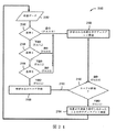
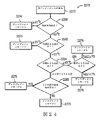
エネルギー源またはエネルギー発生装置26(例えば、RFエネルギー発生装置)は、エネルギー送達要素24を介して、標的処置部位への送達のために選択された形態および規模のエネルギーを発生させるように構成されている。エネルギー発生装置26は、ケーブル28を介して処置デバイス12に電気的に結合させることができる。少なくとも1つの供給ワイヤ(図示しない)が、細長いシャフト16に沿って、または細長いシャフト16の管腔内を、エネルギー送達要素24まで通り、処置エネルギーをエネルギー送達要素24に伝達する。幾つかの実施形態において、各エネルギー送達要素24は、それ自体の供給ワイヤを含む。しかし他の実施形態において、2つ以上のエネルギー送達要素24が、同じ供給ワイヤに電気的に結合されていてもよい。足ペダル32などの制御メカニズムを、エネルギー発生装置26に連結(例えば、空気圧式に連結または電気的に連結)させて、オペレータに、非限定的に電力送達をはじめとする発生装置の様々な操作特性を開始、終了および場合により調整させてもよい。システム10は、滅菌区域に配置させてエネルギー送達要素24に動作可能に結合させることができる遠隔制御デバイス(図示しない)を含んでいてもよい。遠隔制御デバイスは、電極を選択的に接続/切断させるように構成されている。別の実施形態において、遠隔制御デバイスは、ハンドルアセンブリ34内に構築されていてもよい。エネルギー発生装置26は、自動制御アルゴリズム30を介して、そして/または医師の制御の下で、処置エネルギーを送達するように構成されていてもよい。加えてエネルギー発生装置26は、1つ以上の評価またはフィードバックアルゴリズム31を含んで、治療前、治療時、および/または治療後に医師にフィードバックを提供してもよい。適切な制御アルゴリズムおよび評価/フィードバックアルゴリズムに関する更なる詳細は、図20〜27を参照しながら以下に記載する。
An energy source or energy generator 26 (eg, an RF energy generator) is configured to generate energy of a selected form and scale for delivery to a target treatment site via an
幾つかの実施形態において、システム10は、エネルギー送達要素24を介して単極電場の送達を提供するように構成されていてもよい。そのような実施形態において、中性または分散電極38が、エネルギー発生装置26に電気的に結合されていてもよく、そして患者の体外に付着されていてもよい(図2に示す)。加えて、1つ以上の温度(例えば、熱電対、サーミスタなど)、インピーダンス、圧力、光学的、流動、化学的または他のセンサなどの1つ以上のセンサ(図示しない)が、エネルギー送達要素24の付近またはその内部に配置されてもよく、そして1つ以上の供給ワイヤ(図示しない)に連結されていてもよい。例えば、合計2本の供給ワイヤが含まれていてもよく、その両方のワイヤが、センサからのシグナルを伝達し、一方のワイヤが二重の目的で作用することができ、エネルギーをエネルギー送達要素24に伝送してもよい。あるいは異なる数の供給ワイヤを用いて、エネルギーをエネルギー送達要素24に伝達してもよい。
In some embodiments, the system 10 may be configured to provide unipolar electric field delivery via the
エネルギー発生装置26は、マイクロプロセッサなどの処理回路網およびディスプレイを含み得るデバイスまたはモニターの一部であってもよい。処理回路網は、制御アルゴリズム30に関係する記憶命令を実行するように構成されていてもよい。モニターは、処置デバイス12と(例えば、ケーブル28を介して)連通して、エネルギー送達要素24への電力を制御するよう、そして/またはエネルギー送達要素24もしくは任意の関連するセンサからシグナルを得るように構成されていてもよい。モニターは、聴覚、視覚もしく他の表示などの電力レベルもしくはセンサデータの表示を提供するように構成されていてもよく、または情報を別のデバイスに情報を連絡するように構成されていてもよい。例えばエネルギー発生装置26は、処置情報を表示するカテーテルラブスクリーンまたはシステムに動作可能に結合されるように構成されていてもよい。
The
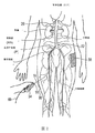
図2(図30の追加的参照を含む)に、システム10の実施形態を用いて腎神経をモジュレートすることを示す。処置デバイス12は、血管内進路Pを通した腎神経叢RPへのアクセス、例えば各腎動脈RA内の標的処置部位までの大腿動脈(図示)、上腕動脈、橈骨動脈および腋窩動脈内の経皮アクセス部位を提供する。図示された通り、シャフト16の基端部分18の区分は患者の体外に暴露されている。医師は、血管内進路Pの外側からシャフト16の基端部分18を操作することにより、一部蛇行した血管内進路P内でシャフトを進行させ、シャフト16の先端部分20を遠隔操作してもよい。画像誘導、例えばコンピュータ断層撮影法(CT)、蛍光透視法、血管内超音波法(IVUS)、光コヒーレンストモグラフィー(OCT)、もしくは別の適切な誘導モダリティ、またはそれらの組み合わせを用いて、医師の操作を援助してもよい。更に幾つかの実施形態において、画像誘導構成要素(例えば、IVUS、OCT)が、処置デバイス12自体に組み入れられていてもよい。治療アセンブリ21が、腎動脈RA内に適切に配置された後、それをハンドル34または他の適切な手段を用いて、エネルギー送達要素24が腎動脈RAの内壁と安定して接触するようになるまで放射状に展開させるか、または他の方法で配備させることができる。その後、エネルギー送達要素24からのエネルギーの目的に応じた適用を組織に施して、腎動脈RAの外膜の内部、またはそれに隣接して、またはそれに接近して存在する、腎動脈の局在的領域および腎神経叢RPの隣接領域に対する1つ以上の所望のニューロモジュレーション効果を誘導する。エネルギーの目的に応じた適用により、腎神経叢RPの全てまたは少なくとも一部に沿ってニューロモジュレーションを実現してもよい。
FIG. 2 (including the additional reference of FIG. 30) illustrates modulating the renal nerve using an embodiment of the system 10. The
ニューロモジュレーション効果は、一般に、少なくとも一部は電力、時間、エネルギー送達要素24と血管壁との接触、および血管内の血流の関数である。ニューロモジュレーション効果は、除神経、熱アブレーション、およびノンアブレーティブな熱変化または損傷(例えば、持続的加熱および/または抵抗加熱)を含んでいてもよい。所望の熱的加熱効果は、標的神経線維の温度を所望の閾値を超えて上昇させてノンアブレーティブな熱変化を実現すること、またはより高温を超えて上昇させてアブレーティブな熱変化を実現することを含んでいてもよい。例えば標的温度は、ノンアブレーティブな熱変化の場合には体温(例えば、およそ37℃)を超え約45℃未満であってもよく、または標的温度は、アブレーティブな熱変化の場合には約45℃以上であってもよい。所望の非熱的ニューロモジュレーション効果は、神経において伝達される電気シグナルを変化させることを含んでいてもよい。
The neuromodulation effect is generally at least in part a function of power, time, contact between the
幾つかの実施形態において、治療アセンブリ21のエネルギー送達要素24は、支持構造22の近位にあっても、それに隣接しても、またはそれにより運搬されてもよい(例えば、支持構造に接着されても、縫い込まれても、巻き付けられても、そして/または圧着されてもよい)。支持構造22の基端は、好ましくは継手(図示しない)を介して細長いシャフト16の先端20に連結されている。継手は、細長いシャフト16の一体となった構成要素であってもよく(即ち、別個の部品でなくてもよく)、または継手は、支持構造22を細長いシャフト16に締結するための、細長いシャフト16の外表面の周りをくるむ環(例えば、放射線不透過性バンド)などの別個の部品であってもよい。しかし別の実施形態において、支持構造22は、別の配列および/または異なる特色を利用して、細長いシャフト16と関連していてもよい。
In some embodiments, the
更に別の実施形態において、エネルギー送達要素24は、支持構造22自体の選択された部分、またはその全体を形成または画定していてもよい。即ち、以下に更に詳細に記載される通り、支持構造22は、エネルギーを送達することが可能であってもよい。その上、幾つかの実施形態において、治療アセンブリ21は、1つのエネルギー送達要素と共に機能してもよいが、治療アセンブリ21が、好ましくは支持構造22に関連する、またはそれを画定するエネルギー送達要素24を複数含んでいることは理解されよう。複数のエネルギー送達要素24が提供される場合、エネルギー送達要素24は、同時、選択的、もしくは連続のいずれかで、電力を独立して送達してもよく(即ち、単極方式で利用してもよく)、そして/または該要素の任意の所望の組み合わせの間に電力を送達してもよい(即ち、双極方式で用いてもよい)。更に医師は、場合により、様々な形状またはパターンを有する腎動脈内で高度にカスタマイズされた病変(複数可)を形成させるために、どのエネルギー送達要素(複数可)24が電力送達に用いられるかを選択してもよい。
In yet another embodiment, the
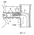
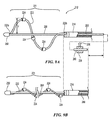
図3Aに、腎動脈RA内で送達状態(例えば、低プロファイルまたは折り畳み構成)にあるシャフト16の先端部分20および治療アセンブリ21の一実施形態を示す断面図であり、図3Bおよび3Cは、腎動脈内で配備状態(例えば、展開または螺旋構成)にある治療アセンブリ21を示す。最初に図3Aを参照すると、治療アセンブリ21の折り畳みまたは送達配列が、アセンブリの長手方向軸A−Aの周りの低プロファイルを画定していることで、治療アセンブリ21の横断寸法は、動脈壁55と治療デバイス12の間に空間距離を画定するのに十分小さい。送達状態により、処置デバイス12の挿入および/または除去、そして所望なら腎動脈RA内での治療アセンブリ21の再配置が容易になる。
FIG. 3A is a cross-sectional view illustrating one embodiment of the
折り畳み構成では、例えば支持構造22の幾何学的配置により、ガイドカテーテル90を通した、腎動脈RA内処置部位までの治療アセンブリ21の移動が容易になる。その上、折り畳み構成では、治療アセンブリ21は、腎動脈RA内に適合するようなサイズおよび形状であり、腎動脈の内径52よりも小さい径および腎動脈の長さ54よりも短い(治療アセンブリ21の基端から治療アセンブリ21の先端までの)長さを有する。更に、以下により詳細に記載される通り、支持構造22の幾何学的配置は、腎動脈の内径52よりも小さい中心軸の周りの最小横断寸法、および好ましくは腎動脈の長さ54よりも小さい、中心軸方向の最大長を画定(送達状態)するようにも配列されている(送達状態)。一実施形態において、例えば治療アセンブリ21の最小径は、細長いシャフト16の内径とほぼ等しい。
In the folded configuration, for example, the geometry of the
シャフト16の先端部分20は、実質的な様式で屈曲して、ガイドカテーテル、ガイドワイヤ、またはシースにより確定される通路に従うことにより各左/右腎動脈内に進入してもよい。例えば先端20の屈曲が、経皮挿入部位から腎動脈RAまでの所望の通路に沿ってシャフト16を案内する先端付近にプリフォームされた屈曲部を有する、腎臓ガイドカテーテルなどのガイドカテーテル90により付与されてもよい。別の実施形態において、処置デバイス12は、腎動脈RA内に挿入されて経皮アクセス部位まで伸長するガイドワイヤ(例えば、図2のガイドワイヤ66)と係合して、それを追跡することにより、腎動脈RA内の処置部位に案内されてもよい。操作において、ガイドワイヤは、好ましくは最初に腎動脈RA内に送達され、その後、ガイドワイヤの管腔を含む細長いシャフト16が、ガイドワイヤを通して腎動脈RA内に通される。幾つかのガイドワイヤ手順において、管状送達シース1291(図16Aおよび16Bを参照して以下により詳細に記載される)は、ガイドワイヤ(即ち、ガイドワイヤを通した送達シースの滑動により画定される管腔)を通して腎動脈RA内に通される。送達シース1291(図16A)が、腎動脈RA内に配置されると、ガイドワイヤが除去されて、送達シース1291を通して腎動脈RA内に送達され得る処置カテーテル(例えば、処置デバイス12)に交換されてもよい。更に、幾つかの実施形態において、先端部分20は、例えば動作可能な要素36または別の制御要素により、ハンドルアセンブリ34(図1および2)を介して腎動脈RA内に指向または操縦させることができる。特に細長いシャフト16の屈曲は、参照により全体が本明細書に組み入れられた、Wu他への米国特許出願第12/545,648号、”Apparatus, Systems, and Methods for achieving Intravascular, Thermally−Induced Renal Neuromodulation”に示された通り遂行してもよい。代替または追加として、処置デバイス12およびその先端部分20は、ガイドカテーテルの基端からの操作により調整または再形成され得る先端付近のプリフォームされた、または操縦可能な屈曲部分を含む操縦可能なガイドカテーテル(図示しない)を通して挿入されることにより屈曲されてもよい。
The
細長いシャフト16をはじめとする処置デバイス12および治療アセンブリ21のエネルギー送達要素24の任意の区分の最大外寸法(例えば、径)は、デバイス12を通過するガイドカテーテル90の内径により画定することができる。1つの特別な実施形態において、例えば、内径およそ0.091インチ(2.31mm)を有する8フレンチガイドカテーテルが、腎動脈に接近するガイドカテーテルとして用いられてもよい。エネルギー送達要素24とガイドカテーテルの間の合理的な間隙許容値(clearance tolerance)を可能にすれば、治療アセンブリ21の最大外寸法が、一般におよそ0.085インチ(2.16mm)以下になる。エネルギー送達要素24を運搬する実質的に螺旋形の支持構造を有する治療アセンブリでは、展開または螺旋形の構成が、好ましくは、およそ0.085インチ(2.16mm)以下の最大幅を画定する。しかし、より小さい5フレンチガイドカテーテルを使用するには、処置デバイス12に沿ったより小さな外形の使用が必要となる可能性がある。例えば、5フレンチガイドカテーテル内を走る螺旋形支持構造22を有する治療アセンブリ21は、約0.053インチ(1.35mm)以下の外寸法または最大幅を有する。更に別の実施形態において、エネルギー送達要素とガイドカテーテルの間に十分な間隙が存在することが前提であれば、実質的に0.053インチ(1.35mm)未満の最大幅を有する治療アセンブリ21を有することが望ましくなり得る。その上、幾つかの実施形態において、ガイドカテーテルおよび治療アセンブリ21が、約1.5:1の口径比を画定する配列を有することが望ましくなり得る。別の実施例において、6フレンチガイドカテーテル内を送達される螺旋構造およびエネルギー送達要素24は、0.070インチ(1.78mm)以下の外寸法を有する。更なる実施例において、他の適切なガイドカテーテルが用いられてもよく、処置デバイス12の外寸法および/または配列は、それに応じて変動させることができる。
The maximum outer dimension (eg, diameter) of any section of the
腎動脈RA内のシャフト16の先端部分20に治療アセンブリ21を配置させた後、治療アセンブリ21は、送達状態から配備状態または配備配列に変換される。その変換は、特別な実施形態およびその様々な配備様式に関して本明細書に記載された通り、デバイスの構成要素の配列を用いて開始されてもよい。以下により詳細に記載された通り、そして本発明のテクノロジーの1つ以上の実施形態によれば、治療アセンブリは、例えば治療アセンブリの支持構造と内部または外部で係合された引張のしくは張力ワイヤ、ガイドワイヤ、シャフトまたは探査針などの制御部材により配備されて、アセンブリに変形または成形力を加え、それを配備状態に変換してもよい。あるいは治療アセンブリ21は、放射状の抑制を解くとアセンブリが配備されるように、アセンブリ自己展開または配備していてもよい。更に、治療アセンブリ21を送達状態から配備状態へ変換するのに用いられるモダリティにより、ほとんどの実施形態において、治療アセンブリ21を再度、配備状態から送達状態に戻るように変換してもよい。
After placing the
各腎動脈RA内での支持構造22およびエネルギー送達要素24の更なる操作により、各腎動脈RAの内壁に沿った組織へのエネルギー送達要素24の並置を確立する。例えば図3Bおよび3Cに示す通り、治療アセンブリ21は、エネルギー送達要素24が腎動脈壁55と接触するように、腎動脈RA内で展開される。幾つかの実施形態において、先端部分20の操作により、エネルギー送達要素24と腎動脈壁との接触も容易になる。本明細書に記載された支持構造(例えば、支持構造22)の実施形態は、腎動脈の内壁55とエネルギー送達要素24の間の接触力が、確実に最大値を超えないと予測される。加えて、本明細書に記載された支持構造22または他の適切な支持構造は、好ましくは一定した病巣形成を可能にし得る、動脈壁55に対する一定した接触力を提供する。
Further manipulation of
心合わせは、エネルギー送達要素24と腎動脈壁55との幾何学的態様の心合わせを含んでいてもよい。例えばエネルギー送達要素24が丸い端部を有する円筒形を有する実施形態において、心合わせは、個々のエネルギー送達要素24の長手方向の表面と動脈壁55との心合わせを含んでいてもよい。別の実施例において、実施形態は、構築された形状または不活性な表面を有するエネルギー送達要素24を含んでいてもよく、心合わせは、その構築された形状または不活性な表面が動脈壁55と接触しないようにエネルギー送達要素24を心合わせすることを含んでいてもよい。
The alignment may include a geometric alignment of the
配備状態にある図3Bおよび3Cにおいて最良に見られる通り、治療アセンブリ21は、螺旋形通路に沿って腎動脈壁55と接触する、実質的に螺旋形の支持構造22を画定する。この配列の一利点は、血管の周囲に圧力を加えずに、螺旋構造からの圧力を放射方向に広範に加えることができることである。つまり螺旋形の治療アセンブリ21は、動脈壁が任意の方向に移動した時に、エネルギー送達要素24と動脈壁55との安定した接触を提供すると予測される。更に、螺旋形通路に沿って血管壁55に加えられた圧力が、血管の周囲を緊張または拡張させて血管組織への損傷を引き起こす可能性は低い。展開された螺旋構造の更に別の特色は、それが放射方向に広範囲で血管壁と接触することができ、血管内の管腔を十分に開いた状態に保ち、治療の間に螺旋内の血流を可能にすることである。
As best seen in FIGS. 3B and 3C in the deployed state,
配備状態にある図3Bに最良に見られる通り、支持構造22は、主な腎動脈(即ち、分岐部に近い腎動脈の区分)の腎動脈長54とほぼ等しいか、またはそれ未満である治療アセンブリ21の最大軸長を画定する。この長さは、患者により変動し得るため、配備された螺旋形の支持構造22が、異なる患者に適し得る異なるサイズに組み立て得ることが想定される(例えば、図4Aに示す通り長さLおよび/または径Dが変動する)。配備状態にある図3Bおよび3Cを参照すると、螺旋形の治療アセンブリ21は、エネルギー送達要素24と動脈RAの内壁55の間に周辺に沿って不連続な接触を提供する。即ち、螺旋形通路は、血管の長手方向軸の周りに血管の内壁に沿って、部分的な円弧(即ち、<360°)、完全な円弧(即ち、360°)または完全な円弧を超えるもの(即ち、>360°)を含んでいてもよい。しかし幾つかの実施形態において、円弧は、実質的に、動脈の中心軸に対して垂直な一平面内に存在せず、代わりに好ましくは、動脈の中心軸と鈍角を画定する。
As best seen in FIG. 3B in the deployed state, the
A.螺旋構造
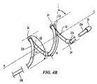
図4Aは、該テクノロジーの実施形態による処置デバイス(例えば、処置デバイス12)と共に使用される治療または処置アセンブリ21の平面図であり、図4Bは、図4Aの治療アセンブリ21の等角図である。図4Aおよび4Bに示されたエネルギー送達要素24は、単に例示を目的としており、処置アセンブリ21が異なる数および/または配列のエネルギー送達要素24を含み得ることは理解されよう。
A. FIG. 4A is a plan view of a treatment or
図4Aおよび4Bに示される通り、螺旋は、少なくとも一部として、全体的な径D、長さL、螺旋角度α(螺旋に対してタンジェントな線とその軸の間の角度)、ピッチHP(軸に対して平行に測定された、1つの完全な螺旋回転分の長手方向距離)、および回転の数(螺旋が軸の周りの360度回転を完了する回数)により特徴づけることができる。 As shown in FIGS. 4A and 4B, the helix, at least in part, has an overall diameter D, length L, helix angle α (angle between a tangent line to the helix and its axis), pitch HP ( It can be characterized by the longitudinal distance of one complete helical rotation measured parallel to the axis) and the number of rotations (number of times the helix completes a 360 degree rotation around the axis).
特に螺旋の配備または展開形態は、例えば血管壁または他の構造により制限されない、自由空間内の伸長軸に沿った軸長Lにより特徴づけることができる。螺旋形支持構造22は、送達状態から放射状に展開するため、径Dは増加し、長さLは減少する。即ち、螺旋構造が、配備した時に、先端22aは、基端22bに向かって軸上を移動する(またはその逆)。したがって配備された長さLは、展開されていない長さまたは送達長よりも小さい。特定の実施形態において、支持構造22の先端部分22aまたは基端部分22bの一方のみが、細長いシャフト16またはその伸長部にしっかりと結合されている。他の実施形態において、支持構造22は、先端部分22aおよび基端部分22bを互いにねじることにより、配備または展開構成に変換されてもよい。
In particular, the helical deployment or deployment configuration can be characterized by an axial length L along the extension axis in free space, not limited by, for example, vessel walls or other structures. As the
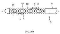
図4Bを参照すると、配備された螺旋形の支持構造22は、場合により、比較的直線の螺旋部分の遠位方向へある遠位伸長部26aを含み、非侵襲的な(例えば、丸い)チップ50で終結していてもよい。チップ50を含む遠位伸長部26aは、螺旋構造が展開して、そして/または送達シースを引っ込めて、血管を損傷するリスクが低下してもよく、それが展開して、血管内の螺旋構造の心合わせが容易にしてもよい。幾つかの実施形態において、遠位伸長部26aは、概ね直線(しかし可撓性)であり、約40mm未満(例えば、2mm〜10mmの間)の長さを有する。チップ50は、接着剤、溶接、圧着、オーバーモールド成形、および/またははんだにより該構造要素の先端に固定されたポリマーまたは金属で製造することができる。別の実施形態において、チップ50は、該構造要素と同じ材料から製造されて、機械加工または融解によりチップ50に組み立てられてもよい。別の実施形態において、遠位伸長部26aは、異なる構成および/または特色を有していてもよい。例えば幾つかの実施形態において、チップ50は、エネルギー送達要素または放射線不透過性マーカを含んでいてもよい。更に遠位伸長部26aは、全ての実施形態に含まれていなくてもよい、任意の特色である。
Referring to FIG. 4B, the deployed
螺旋構造は、場合により、支持構造22の螺旋形の領域に比べ、比較的直線である近位伸長部26bを有していてもよい。例えば近位伸長部26bは、支持構造22の伸長部であってもよく、0mm〜40mmの間(例えば、約2〜約10mmの間)の長さを有していてもよい。あるいは近位伸長部26bは、別個の材料(例えば、ポリマー線維)で構成されていて、支持構造22の残り部分よりも可撓性であってもよい。近位伸長部26bは、支持構造22の螺旋領域と細長いシャフト16の先端の間に可撓性連結を提供するように構成されている(図1)。この特色は、細長いシャフト16から螺旋構造22の螺旋領域まで移動する力を減少させることにより、配備された螺旋形支持構造22と血管壁との心合わせが容易になると予測される。これは、例えば細長いシャフトが血管壁の側面方向に偏向している場合、または細長いシャフトが血管壁に関して移動していて螺旋構造を配置された状態である場合には、有用となり得る。
The helical structure may optionally have a proximal extension 26b that is relatively straight compared to the helical region of the
再度、図4Aおよび4Bを一緒に参照すると(そして図3Aおよび3Bを参照すると)、配備された螺旋形の支持構造22の寸法は、その物理的特徴およびその構成(例えば、展開または非展開)により影響を受け、その一方で腎動脈の幾何学を考慮して選択してもよい。例えば配備された螺旋構造の軸長Lは、患者の腎動脈(例えば、図3Aおよび3Bの腎動脈RAの長さ54)よりも長くならないように選択されてもよい。例えば腎動脈のアクセス部位と口の間の距離(例えば、典型的には約40cm〜約55cmとなる大腿アクセス部位から腎動脈までの距離)は、一般に、腎動脈の長さに沿った大動脈および最も遠位の処置部位からの腎動脈の長さ(典型的には約7cm未満)よりも大きい。したがって、細長いシャフト16(図1)が少なくとも40cmであり、螺旋構造が展開していない長さLでは約7cmよりも小さいと予想される。約4cm以下の展開していない構成の長さは、患者の大部分における使用に適していて、長い接触領域を提供する場合があり、展開構成の場合および幾つかの実施形態において、複数のエネルギー送達要素の配置のための長い領域を提供する場合があるが、展開していない構成のより短い長さ(例えば、約2cm未満)が、短い腎動脈を有する患者において用いられる場合がある。螺旋構造22は、典型的な腎動脈径で作用するように設計されてもよい。例えば、腎動脈RAの径52(図3A)は、約2mm〜約10mmの間で変動してもよい。特別な実施形態において、螺旋構造22上のエネルギー送達要素24の配置が、腎動脈RAに関して腎神経叢RPの推定位置に関して選択されてもよい。
Again referring to FIGS. 4A and 4B (and with reference to FIGS. 3A and 3B), the dimensions of the deployed
別の特別な実施形態において、治療アセンブリ21の区分または支持構造は、制限されていない構成(即ち、図4Aおよび4Bに示された通り体外)に全て配備させる場合には、約15mm未満(例えば、約12mm、10mm、8mm、または6mm)の径D;約40mm以下(例えば、約25mm未満、約20mm未満、約15mm未満)の長さL;約20°〜75°の間(例えば、約35°〜55°の間)の螺旋角度α;0.25〜6の間(例えば、0.75〜2の間、0.75〜1.25の間)の回転範囲;および約5mm〜20mmの間(例えば、約7mm〜13mmの間)のピッチHPを有する螺旋形状を含む。別の実施例において、治療アセンブリ21は、中心軸の周りの径がおよそ10mmである送達状態から、エネルギー送達要素24が動脈壁と接触している送達状態まで放射状に展開するように構成されていてもよい。前述の径/角度は、該テクノロジーの特別な実施形態に関連しており、該テクノロジーの別の実施形態により構成された治療アセンブリが異なる配列および/または形態を有し得ることは理解されよう。
In another particular embodiment, the section or support structure of the
幾つかの実施形態において、配備された螺旋形の支持構造22は、概ね円筒形であってもよい(即ち、螺旋の径は、長さの大部分に沿って概ね一定している可能性がある)。しかし、構造22は、円錐螺旋形状、先細の構造要素、時計回りまたは反時計回りの経路、一定した、または変動するピッチなどの変動を有し得ることも企図される。
In some embodiments, the deployed
一実施形態において、支持構造22は、固体構造要素、例えばワイヤ、管、巻き付けたまたは編み込んだケーブルなどを含むことができる。支持構造22は、生体適合性金属、および/またはポリマー、例えばポリエチレンテレフタラート(PET)、ポリアミド、ポリイミド、ポリエチレンブロックアミドコポリマー、ポリプロピレン、またはポリエーテルエーテルケトン(PEEK)ポリマーから形成されていてもよい。幾つかの実施形態において、支持構造22は、非導電性、導電性(例えば、ステンレス鋼、ニチノール、銀、プラチナ、ニッケル−コバルト−クロム−モリブデン合金)、または導電性材料と非導電性材料との組み合わせであってもよい。1つの特別な実施形態において、例えば支持構造22は、スプリングテンパーのステンレス鋼またはニチノールなどの予備成形材料で形成されていてもよい。更に特別な実施形態において、構造22は、処置アセンブリ21が腎動脈において適切に配置および/または配備されているかを医師に決定させるよう、少なくとも一部が、蛍光画像を撮影することが可能な放射線不透過性材料から形成されていてもよい。放射線不透過性材料は、例えば、硫酸バリウム、三酸化ビスマス、次炭酸ビスマス、粉末タングステン、粉末タンタル、または金とプラチナなど特定の金属の様々な配合剤を含んでいてもよく、これらの材料は、構造要素22に直接組み込まれていてもよく、または螺旋構造22上に部分的もしくは完全なコーティングを形成していてもよい。
In one embodiment, the
一般に螺旋構造22は、挿入および展開されて腎動脈壁55の内表面に接触すると(図3Aおよび3B)、腎動脈壁55に所望の外側への放射力を加えるよう設計されていてもよい(図3Aおよび3B)。放射力を選択して、螺旋構造22が患者の体内で動脈壁55に対して展開すると、腎動脈RAを緊張または拡張させることによる損傷を回避してもよい。腎動脈RAが損傷するのを回避しながら、なおも適当な安定化力を提供し得る放射力は、典型的な血圧により動脈壁に加えられる放射力を計算することにより決定してもよい。例えば適切な放射力は、約300mN/mm以下(例えば、200mN/mm未満)であってもよい。加えられる放射力に影響を及ぼし得る要因としては、支持構造22の幾何学的配置および剛性が挙げられる。1つの特別な実施形態において、支持構造22は、約0.003〜0.009インチ(0.08〜0.23mm)の径である。支持構造22の組成に応じて、構造要素の径は、展開の際に腎動脈に対する所望の快適性および/または放射力を容易にするように選択されてもよい。例えば、より剛性の材料(例えば、金属)から形成された支持構造22は、高可撓性ポリマーから形成された支持構造22に関して薄いことで、類似の可撓性および放射力プロファイルを実現してもよい。螺旋形支持構造22の外部圧力は、関連の圧力変換器によりインビボで評価されてもよい。
Generally, the
加えて、加熱処理およびアニーリングをはじめとする特定の二次的プロセスにより、繊維材料を硬化または軟化させて、強度および剛性に影響を及ぼしてもよい。特にニチノールなどの形状記憶合金では、これらの二次プロセスを変動させて、同じ出発原料に異なる最終的特性を与えてもよい。例えば、弾性範囲または軟性を増加させて、改善された可撓性を付与してもよい。形状記憶合金の二次的プロセスは、変態温度、即ち構造が所望の放射強さおよび剛性を示す温度に影響を及ぼす。形状記憶ニチノールなどの形状記憶特性を用いる実施形態において、この変態温度は、正常な体温(例えば、37℃前後)または約37℃〜45℃の範囲内に設定されてもよい。超弾性ニチノールを含む別の実施形態において、変態温度は、十分に体温未満、例えば0℃未満であってもよい。あるいは螺旋構造は、所望の螺旋形状に熱工作されたニチノールなどの弾性または超弾性材料から形成されていてもよい。あるいは螺旋構造22は、1種以上のポリマーおよび金属などの複数の材料から形成されていてもよい。
In addition, the fiber material may be cured or softened by certain secondary processes, including heat treatment and annealing, affecting strength and stiffness. Especially for shape memory alloys such as Nitinol, these secondary processes may be varied to give different final properties to the same starting material. For example, the elastic range or softness may be increased to provide improved flexibility. The secondary process of shape memory alloys affects the transformation temperature, the temperature at which the structure exhibits the desired radiant strength and stiffness. In embodiments using shape memory properties such as shape memory nitinol, this transformation temperature may be set at normal body temperature (eg, around 37 ° C.) or in the range of about 37 ° C. to 45 ° C. In another embodiment comprising superelastic nitinol, the transformation temperature may be well below body temperature, for example below 0 ° C. Alternatively, the helical structure may be formed from an elastic or superelastic material such as Nitinol that has been heat worked into the desired helical shape. Alternatively, the
再度、図3Bおよび3Cを一緒に参照すると、処置アセンブリ21の支持構造22が、患者に挿入されていない時には、送達状態にある径よりも大きな最大径まで配備し得ることが理解されなければならない。更に、螺旋形の構造22は、最大径が腎動脈RAの管腔径52よりも大きくなるようなサイズになっていてもよい。しかし、螺旋形の構造22は、患者に挿入されて配備状態に変換されると、放射状に展開して腎動脈の管腔に架かり、最大円周区分では、およそ腎動脈RAの径52であるか、またはそれよりもわずかに小さい(例えば、エネルギー送達要素24が間隙の一部を満たす実施例において)。わずかな量の血管拡張を、過度に損傷されずに引き起こすことができ、構造22は、最大円周区分が腎動脈RAの径52よりもわずかに大きくなるよう、または1つ以上のエネルギー送達要素24が腎動脈RAの壁55にわずかに押し込まれるように、展開させることができる。わずかで非損傷的な動脈壁55の拡張を引き起こす螺旋形のアセンブリまたはアレイは、有利には、エネルギー送達要素24と動脈壁55の間に安定した接触力を提供することができ、そして/または呼吸運動および血流の脈動により動脈が移動する場合でも、エネルギー送達要素24を適所に保持することができる。腎動脈RAのこの径52が、患者により変動するため、処置アセンブリ21は、送達径と最大径の間の径範囲を仮定することができてもよい。
Referring again to FIGS. 3B and 3C, it should be understood that the
先に提供された通り、螺旋構成の配備された治療アセンブリ21の1つの特色は、螺旋構造に関連するエネルギー送達要素24が、血管壁と安定して接触するよう配置されて、一定した病変を確実に形成させ得ることである。更に、複数のエネルギー送達要素24は、適切な間隔をあけて螺旋構造に沿って配置されて、標的血管内に所望の病変構成を実現してもよい。先に記載された螺旋構成を有する治療アセンブリ21の複数の実施形態の別の特色は、該アセンブリが展開されて、比較的広範囲の異なる管径内で、そして/または様々な蛇行性で適合し得ることである。
As previously provided, one feature of the helically deployed deployed
B.エネルギー送達要素のサイズおよび構成
本明細書に提供された実施形態が、1つ以上のエネルギー送達要素24と併せて用いられ得ることが理解されなければならない。以下により詳細に記載される通り、エネルギー送達要素24を運搬する配備された螺旋形の構造は、任意の再配置を行わずに腎動脈への治療エネルギー送達を提供するように構成されている。エネルギー送達要素24の例示的実施形態を、図5A〜5Dに示す。螺旋構造22に関連するエネルギー送達要素24は、別々の要素であってもよく、または螺旋構造22の一体となった部分であってもよい。一部の患者において、エネルギー送達要素(複数可)24を使用して、腎動脈の円周の周りに間隔をあけて配置された単一病変または複数の巣状病変を生成することが望ましい場合がある。所望の長手方向および/または円周寸法を有する単一巣状病変、1つ以上の完全に円形の病変、共通の長手方向位置で円周上に間隔をあけて配置された複数の病変、螺旋形の病変、断続的な螺旋病変、概ね線状の病変、および/または共通の円周位置で長手方向に間隔をあけて配置された複数の離れた巣状病変が、代替または追加的に生成されてもよい。更なる実施形態において、エネルギー送達要素24を用いて、様々な他の幾何学的形状またはパターンを有する病変を生成してもよい。
B. Energy Delivery Element Size and Configuration It should be understood that the embodiments provided herein may be used in conjunction with one or more
エネルギー送達要素24のサイズ、形状、および数に応じて、形成された病変が、腎動脈の円周の周りに間隔をあけて配置されてもよく、その同じ形成病変が、腎動脈の長手方向軸に沿って離れて配置されてもよい。特別な実施形態において、各形成病変が血管円周の少なくとも10%を覆って、腎神経叢に影響を及ぼす確率を高めることが望ましい。更に腎臓の除神経を実現するために、血管の基端または先端から見える形成病変のパターンが、腎動脈の円周の周りの少なくともほぼ全体に延在することが望ましいと判断される。言い換えると、各形成病変が、実際の円周の病変または事実上円周の病変のいずれかを生成するパターンで、円周の円弧、および血管の端部から見える病変それぞれを覆うか、隣接する病変もしくは他の病変と接する、または重なる。実際の円周病変を画定する形成病変は、腎動脈の長手方向軸に対して垂直な単一平面内に存在する。そのパターンの病変を1つを超えてそのように形成させることができるが、事実上円周の病変は、単一の垂直平面内に全てが存在し得ない複数の病変により画定される。事実上円周の病変を含む形成病変の少なくとも1つは、他の病変から離れて軸上に配置される。非限定的実施例において、各病変が血管円周の少なくとも1/6に沿って延在する円弧に架かり、得られた病変のパターンが血管の端部から見ると血管円周を完全に含むように、事実上円周の病変が、腎動脈に沿った単一螺旋パターンに生成された6つの病変を含むことができる。しかし他の実施例において、事実上円周の病変は、異なる数の病変を含むことができる。各病変が外膜内および外膜を超えて透過するのに十分深く、それにより腎神経叢に影響を及ぼすことも望ましい。しかし過度に深い(例えば、>5mm)病変は、非標的組織および標的構造(例えば、腎静脈)を妨害するリスクが生じ、そのため制御された深さでのエネルギー処置も望ましい。
Depending on the size, shape, and number of
図4Aおよび4Bに示される通り、エネルギー送達要素24は、螺旋構造22上に所望の配列で分布されてもよい。例えばエネルギー送達要素24の間の軸方向距離は、腎動脈壁55上の個々のエネルギー送達要素24により形成された病変の縁部が重複する、または重複しないように、選択されてもよい。軸方向距離xxまたはyyの一方または両方が、約2mm〜約1cmであってもよい。特別な実施形態において、軸方向距離xxまたはyyが、約2mm〜約5mmであってもよい。別の実施形態において、エネルギー送達要素24は、約30mm離れて配置されていてもよい。更に別の実施形態において、エネルギー送達要素24は、約11mm離れて配置されている。更に別の実施形態において、エネルギー送達要素24は、約17.5mm離れて配置されている。更に、軸方向距離xxは、軸方向距離yyより小さくても、それとほぼ等しくても、またはそれを超えていてもよい。
As shown in FIGS. 4A and 4B, the
エネルギー送達要素24の間隔は、螺旋距離zz、即ち、螺旋構造22の経路に沿ったエネルギー送達要素の間の距離を特徴としてもよい。螺旋距離zzは、エネルギー送達要素24により生成される病変のサイズに基づいて選択されてもよく、そのため病変が重複しても、または重複しなくてもよい。幾つかの実施形態において、エネルギー送達要素24は、長手方向軸および円周上で互いに偏向して配置されている。例えば図4Cは、螺旋構造22の端面図であり、配備された螺旋構造22の円周の、エネルギー送達要素24の互いの角度の偏向または分離を示す。特にエネルギー送達要素24cは、角度150によるエネルギー送達要素24aからの偏向、および角度152によるエネルギー送達要素24bからの偏向である。エネルギーがエネルギー送達要素24a、24b、および24cを介して腎動脈に加えられる時に病変が円周上で重複していても、または重複していなくてもよいように、偏向の角度が選択されてもよい。
The spacing of the
図4Dは、円周上および/または長手方向に重複しているが、螺旋通路に沿って重複していない形成病変340を有する血管の側面図である。より具体的には病変340は、エネルギー送達要素24により形成されて、血管の一端から見て(例えば、図4Cを参照)円周上の重複部341および/または長手方向の重複部342を有することができるが、螺旋長重複を生成せず、代わりに螺旋長の間隙343を形成してもよい。例えばエネルギー送達要素24は、RFエネルギーの電場を血管壁に加えるために電極の形態をとってもよく、そして径が約5mmの病変を生成し、電極が約6〜約7mmの螺旋距離により離れて配置されるように構成されてもよい。エネルギー送達要素24の数および配置に応じて、任意の適切な回転数を有する螺旋病変パターンが、形成されてもよい。そのため、処置デバイス12は、単一エネルギー適用を利用して、複雑な病変パターンを形成してもよい。図4A〜4Cに示された実施形態が例示であり、本質的に概略の可能性があり、互いに厳密に相関していない可能性があり、該テクノロジーの特定の態様を明白にする目的のためだけに示されていることに留意しなければならない。そのため、エネルギー送達要素24の数および配置は、図4A〜4Cのそれぞれにおいて異なっており、特に再配置せずに処置アセンブリ21の1回の配備のみにエネルギーを加えた場合、例示された実施形態により形成された病変は、先に記載された事実上円周上の病変を実現するのに、十分に重複したパターンを生成していなくてもよい。
FIG. 4D is a side view of a blood vessel having a forming
再度、図3Bを参照すると、個々のエネルギー送達要素24は、エネルギー発生装置26に連結されており(図1)、腎動脈の内壁と接触するようなサイズおよび構成である。示された実施形態において、エネルギー送達要素24は、単極または単一極モードで動作されてもよい。この配列において、加えられたRF電場の戻り通路が、例えば不関電極または中性電極とも呼ばれる外部分散電極(図1および2の要素38として示す)により、確立される。RF電場エネルギーの単極適用が、電極に隣接する組織をオーム加熱または抵抗加熱する働きがある。RF電場の適用は、組織を熱で損傷する。処置の目的は、標的神経線維内にニューロモジュレーション(例えば、壊死、熱変化またはアブレーション)を熱的に誘導することである。この熱的損傷は、血管壁内に病変を形成する。あるいはRF電場が、組織を熱で損傷しない振動またはパルス強度により送達され、標的神経内のニューロモジュレーションが、神経シグナルの電気的加工により遂行される。
Referring again to FIG. 3B, the individual
エネルギー送達要素24の活性表面積は、組織と緊密に接触して配置され得る要素24のエネルギー伝達面積として定義される。エネルギー送達要素と血管壁との間に過度に大きな接触面積があれば、組織とエネルギー送達要素の間の境界、またはその周囲が過度に高い温度を生じる可能性があり、それによりこの境界に過度の熱発生が起こり得る。この過度の熱は、円周方向に過度に大きな病変を生じる可能性がある。これにより、血管壁に不適切な熱負荷がもたらされる可能性もある。幾つかの例において、過度の接触は、小さく浅い病変をもたらす可能性もある。エネルギー送達要素と血管壁とが過度に小さい接触であれば、血管壁が表面的に加熱される可能性があり、それにより過度に小さく(例えば血管の円周の<10%)、および/または過度に浅い病変を生じる可能性がある。
The active surface area of the
エネルギー送達要素24と内部血管壁(例えば、腎動脈壁55)の間の接触の活性表面積(ASA)は、血管壁のいたるところでの熱エネルギー場発生の効率および制御に大きく関係し、腎神経叢内の標的神経線維に熱的に影響を及ぼす。エネルギー送達要素のASAは、所望のサイズおよび深さの病変を生成するのに重要であるが、エネルギー送達要素24および電極46のASAと総表面積(TSA)との比も、重要である。TSAに対するASAの比は、2つの方法で病変形成に影響を及ぼす:(1)電場を介した抵抗加熱の度合い、および(2)注入または輸注された生理食塩水などの血流または他の対流冷却要素の影響。例えばRF電場は、電場に暴露される組織の抵抗加熱を介して病変形成を引き起こす。TSAに対するASAの比が高いほど(即ち、電極と組織の接触が大きいほど)、抵抗加熱が大きくなり、例えば形成される病変が大きくなる。以下により詳細に議論される通り、電極の非接触部分を通る血流(TSA−ASA)が、電極の伝導および対流冷却を提供し、それにより血管壁と電極との境界から過剰な熱エネルギーを取り去る。TSAに対するASAの比が過度に高い(例えば、50%を超える)、組織の抵抗加熱が過度に進行して、過剰の熱エネルギーが十分に取り去られず、その結果、過剰の熱が発生し、狭窄傷害、血栓形成および不適当な病変サイズをもたらす可能性が上昇する。TSAに対するASAの比が過度に低いと(例えば、10%)、組織の抵抗加熱が過度に低くなり、その結果、表層が加熱されて、より小さく浅い病変になる。代表的な実施形態において、組織に接触するエネルギー送達要素24のASAは、
![]()
![]()
エネルギー送達要素24のための様々なサイズ制限が、臨床的理由から、ガイドカテーテルの最大の所望寸法により、そして腎動脈の管腔自体のサイズおよび解剖学的構造により課されてもよい。図13および25に示されたような幾つかの実施形態において、エネルギー送達要素24の最大外径(または非円形断面では断面寸法)は、ハンドルアセンブリ34の遠位にある細長いシャフト16の長さに沿って遭遇する最大径であってもよい。これまで議論された通り、臨床的理由から、エネルギー送達要素24の最大外径(または断面寸法)は、細長いシャフト16が血管内進路14を通過することになるガイドカテーテルの最大内径により制限される。8フレンチガイドカテーテル(およそ0.091インチ(2.31mm)の内径を有する)が、臨床的見通しから、腎動脈へのアクセスに用いられる最大の所望のカテーテルであり、エネルギー送達要素24とガイドカテーテルとの合理的な間隙許容値を可能にすると仮定すれば、電極46の最大径は、約0.085インチ(2.16mm)に制限される。8フレンチガイドカテーテルの代わりに6フレンチガイドカテーテルが用いられる場合には、エネルギー送達要素24の最大径は、約0.070インチ(1.78mm)、例えば約0.050インチ(1.27mm)に制限される。5フレンチガイドカテーテルが用いられる場合には、エネルギー送達要素24の最大径は、約0.053インチ(1.35mm)に制限される。
Various size limitations for the
これらの制限および前述の電力送達の考慮に基づけば、エネルギー送達要素24は、約0.049〜約0.051インチ(1.24mm〜1.30mm)の外径を有していてもよい。エネルギー送達要素24は、約0.020インチ(0.51mm)の最小外径を有していて、十分な冷却および病変サイズを提供してもよい。幾つかの実施形態において、エネルギー送達要素24は、約1mm〜約3mmの長さを有していてもよい。エネルギー送達要素24が抵抗加熱要素である幾つかの実施形態において、エネルギー送達要素24は、約0.049〜0.051インチ(1.24mm〜1.30mm)の最大外径および約10mm〜30mmの長さを有する。例えば、エネルギー送達要素24の一実施形態は、支持構造(例えば、管状構造)の周りに配設された電極4〜6個のマルチ電極アレイを提供する。例えば、エネルギー送達要素24が、金電極、あるいはプラチナ、プラチナ−イリジウム、または別の適切な材料であってもよい。1つの特別な実施形態において、電極は、ID約0.030インチ×OD0.0325インチ×長さ0.060インチ(0.76mm×0.83mm×1.52mm)であってもよい。更に別の特別な実施形態において、電極は、ID約0.029インチ×OD0.033インチ×長さ0.060インチ(0.72mm×0.83mm×1.52mm)であってもよい。更に別の特別な実施形態において、電極は、ID約0.038インチ×OD0.042インチ×長さ0.060インチ(0.97mm×1.07mm×1.52mm)であってもよい。その上、電極は、ポリマーのジャケット付き電極それぞれの供給ワイヤーアレイで支持構造から適宜、電気的に絶縁されていることで、支持構造22の周りのコンパクトなジャケット付き電極アレイアセンブリを提供してもよい。
Based on these limitations and the aforementioned power delivery considerations, the
別の実施形態において、処置デバイス12の外径は、1つ以上のエネルギー送達要素24により画定されてもよく、更に図8Aに示される制御ワイヤ168などの要素により画定されてもよい。例えば特別な実施形態は、8フレンチガイドカテーテルと共に使用してもよく、0.049〜約0.053インチ(1.24mm〜1.35mm)の径を有するエネルギー送達要素24(複数可)と、0.005〜約0.015インチ(0.13mm〜0.38mm)の径を有する制御ワイヤとを含んでいてもよい。しかし別の実施形態において、エネルギー送達要素24および/または制御ワイヤの配列および/または寸法は、多様であってもよい。
In another embodiment, the outer diameter of the
特定の実施形態において、螺旋構造22は、導電性材料で形成されてもよい。例えば螺旋構造22は、ニチノールワイヤ、ケーブル、または管で製造されていてもよい。図5Eに示された通り、ワイヤリード19が、螺旋構造22をエネルギー発生装置26に連結していてもよい。螺旋構造22は、腎動脈壁との接触領域を形成し、エネルギー送達要素24として働く。この構成において、螺旋構造22は、連続螺旋病変を生成することが可能である。エネルギー送達要素24となるように構成された螺旋構造22は、場合により、螺旋構造22上、その内部および/または付近に配置されたセンサ33を含んでいてもよく、供給ワイヤ35に電気的に連結されていてもよい。
In certain embodiments, the
別の実施形態において、導電性螺旋構造22は、少なくとも一部が絶縁されている。即ち、導電性螺旋構造は、電気絶縁性材料で部分的に覆われ、螺旋構造22の覆われていない部分が、1つ上の導電性エネルギー送達要素24として働く。エネルギー送達要素24は、任意のサイズ、形状、または数であってもよく、本明細書に提供された通り互いに関して配置されてもよい。
In another embodiment, the conductive
エネルギー送達要素24は、熱エネルギーを送達するように、即ち、加熱して熱エネルギーを組織に伝達するように構成されていてもよい。例えば、電流がエネルギー送達要素を通過すると熱が生じるように、エネルギー送達要素は、電気抵抗ワイヤから製造されたサーモミスタまたはコイルなどの電気抵抗要素であってもよい。例えば電気抵抗ワイヤは、例えば48〜30AWGなどの径を有するニッケル−クロムなどの合金であってもよい。該抵抗ワイヤは、例えばポリイミドエナメルを用いて、電気的に絶縁されてもよい。
The
特定の実施形態において、エネルギー送達要素24は、処置の間に腎動脈に関して角度方向に再配置されてもよい。例えば再度、図1および2を参照すると、この角度方向の再配置は、治療アセンブリ21を押圧して、ハンドルアセンブリ34を介して処置デバイス12の細長いシャフト16を回転させることにより実現されてもよい。エネルギー送達要素24の角度方向または円周方向の再配置に加えて、エネルギー送達要素24は、場合により、腎動脈の長さ方向または長手方向の寸法に沿って再配置されてもよい。この長手方向の再配置は、例えばハンドルアセンブリ34を介して処置デバイス12の細長いシャフト16を移動させることにより実現されてもよく、エネルギー送達要素24の角度方向の再配置の前、後、またはそれと同時に実行してもよい。図3Bを参照すると、エネルギー送達要素24を長手方向および角度方向の両方で再配置させて、腎神経叢RPを処置するための第二の処置部位で、エネルギー送達要素24を腎動脈RAの内壁55と接触するように配置させる。操作において、その後、エネルギーがエネルギー送達要素24を介して送達されて、この第二の処置部位で第二の巣状病変を形成してもよい。複数のエネルギー送達要素24が螺旋構造に関連する実施形態では、最初の処置で2つ以上の病巣を生成してもよく、再配置で追加の病巣を生成させてもよい。
In certain embodiments, the
特定の実施形態において、螺旋形の支持構造22の再配置により生成された病変は、それぞれ腎動脈RAの角度方向および長さ方向の寸法に関して最初の病変(複数可)から角度方向および長手方向に偏向している。エネルギー送達要素(複数可)24の任意の再配置の後の、最初のエネルギー負荷および続いての全てのエネルギー負荷により腎動脈RAに沿って生成された複合病変パターンが、不連続病変を効果的にもたらすことができる(即ちそれは、複数の長手方向および角度方向に間隔をあけて配置された処置部位から形成される)。
In certain embodiments, the lesion created by the repositioning of the
別の実施形態において、エネルギー送達要素24は、導電性ワイヤの形態であってもよい。図5Dに示された通り、例えば、導電性ワイヤ500を螺旋構造22に巻き付けて、コイル電極24’を形成してもよい。コイル電極24’は、エネルギーを送達するために大きな表面積を提供してもよい。例えばコイル電極24’は、一回のエネルギー負荷で概ね連続した螺旋病変を形成してもよい。コイル電極24’を、所望の病変に応じて、螺旋構造22に任意の手法で巻き付けてもよい。例えばコイル電極24’は、螺旋の長さに沿って連続した通路を形成してもよく、またはコイル構造が、非導電性区分により分けられた1つ以上の短い分離電極を形成していてもよい。別の実施形態において、コイル電極24’の部分を螺旋構造上に配置させて、螺旋構造が展開すると血管壁と接触するようにしてもよく、螺旋構造が展開して病変が不連続になる場合には、コイル電極24’の他の部分を血管から離して配置させてもよい。更にそのような配列において、腎動脈に接触しないコイル電極24’の領域が、以下により詳細に記載される通り、エネルギー送達要素24’の冷却に寄与してもよい。エネルギー送達要素24’を形成する導電性部分の配置および数が、所望の病変パターンに従って選択されてもよい。
In another embodiment, the
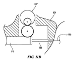
図5Aおよび5Bに示された実施形態において、エネルギー送達要素24は、好ましくは丸まった端部および管腔を有する金属電極を含む。ニチノール製の螺旋支持構造22が、好ましくは電気的に絶縁されており(例えば、PETで)、電極24は、絶縁部の上に搭載されている。供給ワイヤ25が、電極をエネルギー源(図示しない)に連結し、エネルギー(例えば、RF電流)を電極24に送達する。丸まった端部が、血管壁への機械的刺激を低減し、エネルギーが送達された時に、四角または鋭利な端部を有する電極に比較してより一定した電流密度を提供する。あるいはエネルギー送達要素24は、図5Dを参照して先に記載されたコイル電極24’など、記載された他の形態を含んでいてもよい。別の実施形態において、螺旋構造22を形成する構造要素510は、例えば図5Cに見られる通り、エネルギー送達要素24’そのものであってもよい。
In the embodiment shown in FIGS. 5A and 5B, the
III.腎除神経システムの選択的実施形態
本明細書に提供された代表的実施形態は、互いに組み合わせられ得る特色および他の開示された実施形態の特色を含む。これらの実施形態の簡明な説明を提供しようと試みたため、本明細書に記載されたものは、実際の実行の全ての特色ではない。任意の工作または設計計画など、任意のそのような実際の実行を開発することにおいて、数多くの実行に特定した決定を行って、システム関連およびビジネス関連の制限への遵守など開発者に特有の目的を実現して、あらゆる実行に向けて多様であってもよい。
III. Selective Embodiments of Renal Denervation System Exemplary embodiments provided herein include features that can be combined with each other and features of other disclosed embodiments. In an effort to provide a concise description of these embodiments, what is described herein is not all the features of an actual implementation. In developing any such actual execution, such as any work or design plan, make a number of execution-specific decisions, such as complying with system-related and business-related restrictions And may be diverse for any execution.
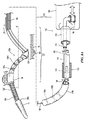
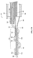
図6Aは、該テクノロジーの実施形態により構成された異なる機械的および機能的領域を有する細長いシャフト116を含む処置デバイス112の実施形態を示す。例えば処置デバイス112の細長いシャフト116は、処置のため、特に腎除神経のために、腎動脈部位への送達および配備のために治療または処置アセンブリ121を有する遠位領域を含む。細長いシャフト116の基端に配設されているのは、細長いシャフト116および治療アセンブリ121の操作のためのハンドルアセンブリ134である。より具体的にはハンドルアセンブリ134は、アクチュエータ136(略図で示す)と共に構成されて、送達状態と配備状態の間で治療アセンブリ121を制御または変換するための制御部材(例えば、図6Eまたは8Aでは制御ワイヤ168)の遠隔操作を提供する。適切なハンドルアセンブリに関する更なる詳細は、例えば、全体が参照により本明細書に組み入れられた、Clarkらへの米国特許出願第12/759,641号、「Handle Assemblies for Intravascular Treatment Devices and Associated System sand Methods」に見出すことができる。
FIG. 6A shows an embodiment of a
処置デバイス112は、治療アセンブリ121が実質的に線状(例えば、直線)となる送達(例えば、低プロファイル)状態の処置部位に治療アセンブリ121を送達して、処置アセンブリ121の支持構造122により運搬されるエネルギー送達要素(図示しない)が、支持部材122に沿って実質的に軸上に心合わせされるように構成されている。ハンドルアセンブリ134は、腎動脈内の処置部位に配置されると、送達状態から配備状態に治療アセンブリ121を変換する制御部材の動作のために、操作される。例えば一実施形態において、制御部材は、管状支持構造122の内部管腔内に配設された制御ワイヤ168(図8A)を含む。制御ワイヤ168の一方の端部は、支持構造122の先端またはその付近に付着されていてもよく、制御ワイヤ168の反対側の端部は、ハンドルアセンブリ134内で終結している。先に述べられた通り、ハンドルアセンブリ134は、制御ワイヤ168を操作して、送達状態と配備状態の間で治療アセンブリ121を変換するように構成されている。制御ワイヤ168の張力が、支持構造122上で作用する、近位方向および軸方向の力を提供する。制御ワイヤ168内の張力の影響下で、患者の腎動脈壁の放射状の制限の影響下にある患者の操作において、支持構造122は、螺旋の幾何学配置に配備してエネルギー送達要素を腎動脈壁と安定して接触させるように変形する。
The
配備の際に所望の変形を提供するために、支持構造122は、支持構造122の周囲に選択的に形成または配設された複数のスロット、カット、スルーホール、および/または開口部を有する管状部材であってもよい。管状支持構造122は、先に記載された支持構造22の特色とほぼ類似した複数の特色を有していてもよい。例えば支持構造122は、PET、ポリアミド、ポリイミド、ポリエチレンブロックアミドコポリマー、ポリプロピレン、またはPEEKポリマーをはじめとする生体適合性金属および/またはポリマーから形成されていてもよく、スロットが、好ましくは所望の構成の管状構造にレーザカットされていてもよい。特別な実施形態において、支持構造122は、非導電性、導電性(例えば、ステンレス鋼、ニチノール、銀、プラチナ−ニッケル−コバルト−クロム−モリブデン合金)、または導電性材料と非導電性材料との組み合わせであってもよい。1つの特別な実施形態において、支持構造122は、スプリングテンパーのステンレス鋼またはニチノールなどの予備成形材料で形成されていてもよい。その上、幾つかの実施形態において、支持構造122は、支持構造122が腎動脈において適切に配置および/または配備されているかを医師に決定させるよう、少なくとも一部が、蛍光画像を撮影することが可能な放射線不透過性材料から形成されていてもよい。放射線不透過性材料は、硫酸バリウム、三酸化ビスマス、次炭酸ビスマス、粉末タングステン、粉末タンタル、または金、プラチナおよびプラチナ−イリジウムをはじめとする特定の金属の様々な配合剤を含んでいてもよく、これらの材料は、支持構造122に直接組み込まれていてもよく、または支持構造122の部分的もしくは完全なコーティングを形成していてもよい。
In order to provide the desired deformation during deployment, the
支持構造122の周りに形成または配設されたスロット、カット、スルーホール、および/または開口部の位置、配向および/または構成は、該構造の変形を画定する。その上、スロット、カット、スルーホール、および/または開口部は、該構造に沿った様々な変形領域を画定するように、管状構造122に沿って変動してもよい。例えば、図6Aに示された実施形態において、管状構造122は、遠位の歪み領域122aと、遠位の歪み領域122aより近位の中間配向領域122bと、配向領域122bより近位の移行領域または可撓性領域122cとを含む。以下により詳細に記載される通り、歪み領域122aは、配備の際に実質的に螺旋の幾何学構造を有するように構成されている。配向領域122bは、細長いシャフト116の長手方向軸Bから離れて、腎動脈壁に向かって、歪み領域122aを配置させる、または傾かせるように構成されている。細長いシャフト112が、経皮アクセス部位から各腎動脈内の標的処置部位までの一部蛇行した血管内進路を進むため、移行領域122cは、処置デバイス112に可撓性を提供するように構成されている(図2を参照して記載された)。処置デバイス112の異なる領域の様々な機械的および機能的態様に関する更なる詳細を、以下に記載する。
The location, orientation, and / or configuration of slots, cuts, through holes, and / or openings formed or disposed around the
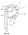
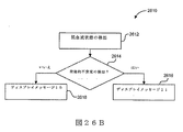
図6Bは、該テクノロジーの一実施形態により構成されたスロットパターンの平面図である。図6Aおよび6Bを一緒に参照すると、例えば歪み領域122aは、螺旋方式で支持構造122に沿って配列された複数の実質的に等しい長さの横断スロット128により画定されてもよい。配向領域122bは、少なくとも2つのスロットの長さが異なる複数の軸上に間隔をあけて配置された横断スロット130により画定されてもよい。更に図6Aに最良に見られる通り、配向領域122bは、歪み領域122aよりも小さい軸長を有することができる。移行領域122cは、配向領域122bよりも近位に位置し、歪み領域122aおよび配向領域122bのそれぞれよりも大きな軸長を有する。例示的な実施形態において、移行領域122cは、支持構造122に沿って様々なピッチを有する連続の螺旋形カットまたはスリット132を含むことができる。例えば一実施形態において、螺旋形カット132のピッチは、細長いシャフト116に沿って近位方向に増加することができる。処置デバイス112の領域の様々な機械的および機能的態様に関する更なる詳細を、以下に記載する。
FIG. 6B is a plan view of a slot pattern constructed in accordance with one embodiment of the technology. With reference to FIGS. 6A and 6B together, for example, the
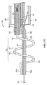
図6Cは、本発明のテクノロジーの実施形態により患者の体外の送達状態(例えば、低プロファイルまたは折り畳み構成)にある支持構造122を含む処置デバイス112の斜視図であり、図6Dは、配備状態(例えば、展開構成)にある支持構造122の斜視図である。理解を容易にするために、図6Cおよび6Dにおける支持構造122は、支持構造122の周りに配設されたエネルギー送達要素を含まずに示されている。
6C is a perspective view of a
図6Cおよび6Dを一緒に参照すると、支持構造122は、長手方向軸B−Bを画定する中央管腔を有する管状部材を含む。先に記載された通り、支持構造122は、近位にある概ね可撓性の移行領域122cと、中間の配向領域122bと、遠位の歪み領域122aとを含む。支持構造122は、少なくとも1つの近位方向の軸成分を有し、好ましくは先端126aまたはその付近に加えられた力を適用して、遠位歪み領域122aおよび中間配向領域122bを変換することにより、送達状態(図6C)と配備状態(6D)とで選択的に変換可能である。一実施形態において、例えば少なくとも部分的に近位方向に向けられた、先端126aまたはその付近に加わる軸方向の力が、支持構造122の遠位歪み領域122aを歪ませて、それが図6Dに示されるような螺旋形の支持構造を形成して(例えば、腎動脈内)、1つ以上のエネルギー送達要素(図示しない)を腎動脈の内壁と接触させる。
Referring to FIGS. 6C and 6D together, the
偏向領域
先に述べられた通り、所望の歪みおよび配備構成を有する支持構造122を提供するために、歪み領域122aは、複数のスロット128a、128b、128c・・・128nを含む。更に複数のスロット128a〜128nは、長手方向軸B−Bの周りに選択的に形成、間隔をあけて配置、および/または配向されることで、遠位歪み領域122aは、予測可能な手法で歪んで、腎動脈内で配備状態の螺旋形幾何学的配置を形成する。遠位領域122aの歪みを放射状に制限し得る腎動脈または他の管腔の外側で、遠位領域122aが、例えば図6Eに示された実質的に円形の幾何学的配置など、完全に展開した構成の非螺旋形幾何学的配置を画定してもよい。そこに示された通り、制御ワイヤ168は、支持構造122の中央管腔内に配設され、先端126aまたはその付近に固着されている。制御ワイヤ168が、近位方向に張力の下に配置されている時に、偏向領域122a(放射方向の任意の制限が存在しない)の少なくとも一部は、図6Cの実質的に直線形状から歪んで図6Eの実質的な円形を形成している。より具体的に図6C〜6Eを一緒に参照すると、偏向領域122aの一部が歪んでいるため、歪みスロット128a〜nが変形して閉じているか、またはほぼ閉じており(図6Eに略図として示す)、各スロット128内の中央領域を囲む支持構造122の縁部の間に接触を提供している。スロットの構成に関する更なる詳細を、以下に記載する。
Deflection Region As previously described, to provide a
偏向領域122aは、曲率中心Zの周りで歪んで、支持部材122の第一の表面122dに関する第一の曲率半径rと、第二の表面122eに関する第二の曲率半径Rとを画定するように配列されている。第二の曲率半径Rは、第一の曲率半径rよりも大きく、その差は、外表面で測定された支持部材122の幅または径dである。例えば腎動脈の内壁の放射状の制限下では、歪み領域122aは、変形して、放射状制限なしに画定された実質的に円形の代わりに、実質的に螺旋形の配備形状を画定する(図6Dに示す)。つまり実質的に螺旋形の配備形状の割合は、歪み領域122aが変形された管腔(例えば、腎動脈の管腔)の内径に応じて多様であってもよい(図6Eに示す)。
The
スロット128a〜128n(図6C)の配列および構成は、歪むことが可能な先端領域122aの幾何学的配置を更に画定する。例えば図6Fは、該テクノロジーの一実施形態によるスロット128のスロットパターンを略図として示し、支持部材122の歪み領域122aの周りのスロットの間隔をあけた配置および配向を示す。4つのみのスロット128a〜dを図6Fに示すが、歪み領域122aが、任意の数の所望のスロット128を有し得ることは、理解されよう。図6Eおよび6Fを一緒に参照すると、スロット128の中心は、累進軸(progressive axis)C−Cに沿って配設、および間隔をあけて配置される。累進軸C−Cは、支持構造122(図6A)の長手方向軸B−Bに対して累進角度θを画定して、未制限の配備状態にある曲率中心Z(図6E)の周りにγの間隔で角度を画定する。スロット128a〜128dの中心は、距離xで実質的に等間隔の配置として示される。しかし、あるいはスロットの中心間隔が、累進軸C−Cに沿って多様であってもよい(×1、×2など)。各スロット128は、長手方向軸B−Bの周りの最大弧長Lと、長手方向軸B−Bの方向の最大スロット幅Wとを画定する。
The arrangement and configuration of the
歪みの下での領域122aのスロット128の総数を、特定の長さに存在するスロット幅Wで掛け合わせると、歪み領域122aの偏向部分の第一の曲率半径rが画定される(未制限の配備状態で設置された場合)。例えば1つの特定の実施形態において、各スロットのma(slot ma)は、約0.0005〜0.010インチ(0.01〜0.25mm)の範囲内の幅Wおよび約0.0005〜0.010インチ(0.01〜0.25mm)のスロット弧長を有していて、約3.5〜6mm(径7〜12mm)の範囲内の非制限的歪み状態にある第一の曲率半径rを画定する。支持部材122の偏向領域122aを通して軸方向の力を最大負荷時の第一の曲率半径rを最小にすると、偏向領域122aの可撓性が規定される。したがって、第一の曲率半径rが小さいほど可撓性が大きくなり、第一の曲率半径rが大きいほど剛性が大きくなる。つまり支持部材122の偏向領域122aの可撓性および/または剛性は、先端領域122aのスロットの数および/または幅を選択することにより規定することができる。例えば一実施形態において、歪み領域122aは、およそ2〜100のスロットを含むことができ、それぞれが0.0005〜0.010インチ(0.01〜0.25mm)の範囲内のスロット幅Wおよび0.0005〜0.010インチ(0.01〜0.25mm)のスロット弧長Lを有して、約3.5〜6mm(径7〜12mm)の範囲の非制限的歪み状態での第一曲率半径rを画定することができる。
Multiplying the total number of
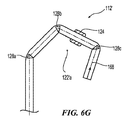
偏向領域122aの第一の曲率半径rは、スロット128の数に直接関係するため、スロット128の数を非常に少なくすることで、歪み領域122aの区分の非連続的な曲率半径を提供して、その区分を実質的に多角形にしてもよい。図6Gは、例えば該テクノロジーの別の実施形態により構成された処置デバイス112’の略平面図である。処置デバイス112’の歪み領域122’aが、先端の張力負荷の下にある場合の(即ち、制御ワイヤ168から)実質的に多角形の幾何学的配置を画定するように、歪み領域122’aが、少ない、または少数の偏向スロット128を含んでいてもよい(例えば、3つのスロット128a〜cが図示される)。別の実施形態において、異なる数のスロット128を用いて、処置デバイス112’の所望の幾何学的配置を選択的に形成してもよい。
Since the first radius of curvature r of the
再度、図6Bおよび6Cを参照し、そしてこれまでの記載の通り、歪み領域112aは、各スロット128が支持構造122の長手方向軸B−Bに対して実質的に横断して伸長し、スロット128が実質的に類似の弧長である、複数の歪みスロット128により画定される。その上、図6Fを参照すると、歪み領域122aのスロット128が、軸方向の支持構造122に沿って概ね渦巻方式で進行するように、歪み領域122aのスロット128の中心は、長手方向軸BBから傾いた、一般に累進軸C−Cに沿って離れて配置される(図6Cで最良に見られる)。配備状態におかれている時に(例えば、腎動脈内)、好ましくは螺旋の幾何学的配置を形成するような予測可能な手法で、歪み領域122aが歪む、または変形するように、歪み領域122aの複数のスロット128が、長手方向軸B−Bの周りに選択的に形成、間隔をあけて配置、および/または配向される。
Referring again to FIGS. 6B and 6C, and as previously described, the strained regions 112a extend so that each
例えば再度、図6Bを参照すると、歪み領域122aは、該テクノロジーの一実施形態により配列された歪みスロット128のパターンを含み、支持部材122の周りのスロットの間隔をあけた配置、または配向を示す。歪みスロット128の中心は、累進軸C−Cに沿って配設され、そして間隔をあけて配置される。累進軸C−Cは、支持構造122の長手方向軸B−Bに対して累進角度θ1を画定する(図6A)。累進角度θ1は、配備状態にある時の支持構造122により画定される螺旋形の幾何学的配置のピッチ角度を画定し、より特別には直接それに対応する。累進角度θ1は、例えば、約零度(0°)〜約6度(6°)の範囲内、例えば1/2度(0.5°)、2度(2°)などであってもよい。歪みスロット128の中心は、実質的に等間隔での配置として示されている。しかし他の実施形態において、スロット128の間で間隔をあけて配置された中心は、累進軸C−Cに沿って多様であってもよい。歪み領域122aを画定するスロット128の総数は、約2〜100のスロット(例えば、約80のスロット)であってもよい。1つの特別の実施形態において、偏向領域122aの合計軸長は、約1インチ(2.54cm)である。しかし他の実施形態において、偏向領域122aは、異なる数のスロット128を有することができ、そして/またはスロットは、互いに関して異なる寸法もしくは配列を有することができる。
For example, referring again to FIG. 6B, the
一実施形態において、偏向スロット128のそれぞれは、シャフト116の中心の長手方向軸B−Bの周りに、それに対してほぼ垂直に伸長する実質的に長方形の中央領域129aを含む。中央領域129aの細長い側壁は、それらの間のスロット幅W(例えば、約0.0015インチ(0.038mm))を画定して、領域122aの歪みの間にスロット128が変形すると閉鎖され得る最大の間隙を画定する。各スロット128は、中央領域129aと連通または隣接する側方領域129bを更に含む。一実施形態において、側方領域129bは、実質的に円形であり、径(例えば、0.0060インチ(0.15mm))を有していて、スロット128の端部の応力緩和のための領域を画定する。実質的に円形の側方領域129bの中心の間の間隔が、構造122の長手方向軸の周りに弧長L(例えば、0.040インチ(1.02mm))を画定する。幾つかの実施形態において、これらの側方領域129bは、支持構造122、122’、122’’の長手方向軸B−Bに関して非垂直角上に楕円形のカットとして形成されてもよい。
In one embodiment, each of the
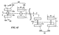
偏向スロットの交互構成が、可能である。例えば、より具体的には偏向スロットを形成して、支持部材122の偏向領域122a内に所望の可撓性および偏向を提供してもよい。例えば図6Hおよび6Iに、該テクノロジーの別の実施形態により構成された偏向スロット128’を有する偏向領域122a’’を示す。この実施形態において、偏向スロット128’は、累進軸C−Cに対して実質的に横切って伸長し、累進軸C−Cの周りを実質的に対称である。例えばスロット128’は、概ね「I形」であってもよく、累進軸C−Cに対して垂直に伸長された中央領域129aを含み、2つの拡大された側方領域129bが中心のスロット領域129aの周りに配設されている。更に、側方領域129bのそれぞれの境界線を形成する支持構造122’’の壁は、好ましくは支持構造122’’の長手方向軸B−Bに実質的に平行に伸長する実質的に長方形の幾何学的配置を画定し、長方形の開口部の角が半形をなす(radiused)。スロット128’の中領域129aは、側方領域129bと連通して形成された実質的に円形の切り抜き領域129cを含むことができる。あるいは幾つかの実施形態において、スロット128’の中央領域129cは、概ね長方形であってもよく、円形の切り抜きを含んでいなくてもよい。
Alternate configurations of deflection slots are possible. For example, more specifically, a deflection slot may be formed to provide the desired flexibility and deflection within the
図6Iに最良に見られる通り、遠位スロット128’は、例えば約0.05インチ(1.27mm)未満、例えば約0.04インチ(1.02mm)の弧長L’の、支持構造122’’の長手方向軸B−Bの周りに伸長する。側方領域129bは、例えば約0.03インチ(0.76mm)である偏向スロット128’の最大幅W’を画定する。中央領域129aの円形部分129cは、側方領域と隣接または連通しており、例えば約0.01インチ(0.25mm)の径を有する中央の円形切り抜き129cを含む。中央領域129aは、支持構造の長手方向に例えば約0.02インチ(0.51mm)の最小幅を画定する。1つの特別な実施形態において、遠位領域のスロット128’の合計数は、30スロット未満(例えば、25スロット)であり、スロットの間隔はm約0.03〜0.04インチ(0.76〜1.02mm)であり、スロットは、遠位の偏向領域122’’内で等間隔で離れている。しかし別の実施形態において、遠位領域は、異なる数のスロットを有していてもよく、そして/またはスロットが、異なる配置(例えば、異なる寸法、スロット間の異なる、または等しくない間隔)を有していてもよい。
As best seen in FIG. 6I, the
交互のスロット、カット、および/または開口部の構成は、所望の可撓性、応力緩和または他の性能特色を提供することができる。例えば図6Jは、支持構造122の偏向領域122aまたは配向領域122b(以下により詳細に記載)のいずれかにおいて、用いられ得る交互のスロット配列128’’である。例示的スロット128’’は、支持構造の長手方向軸B−Bの周りに、それに対して実質的に垂直に伸長する中央領域129’aを含む。中央領域129’aの反対側の側方壁は、概ね弓形であり、それぞれが曲率半径(例えば、約0.06インチ(1.52mm))、およびその間の最大ギャップWWW(例えば、約0.005インチ(0.13mm))を画定して、支持構造122の偏向の間に部分的または完全に閉じられ得る最大スロットギャップを画定する。更に、支持構造の長手方向軸B−Bの周りに配設されるのは、中央領域129’aと連通または隣接する側方領域129’bである。側方領域129’bは、実質的に円形であり、それぞれが径(例えば、0.005インチ(0.13mm))を有して応力緩和のための領域を画定する。曲がった側方領域129’’bの中心の間の間隔が、支持構造122の長手方向軸B−Bの周りに長さLLL(例えば、0.04インチ(1.02mm))を画定する。これらの側方領域129’bは、シャフトの長手方向軸に関して非垂直角上に、例えば楕円形のカットを形成してもよい。
Alternate slot, cut, and / or opening configurations can provide the desired flexibility, stress relief, or other performance features. For example, FIG. 6J is an
細長いシャフトの歪み領域122aおよび/または配向領域122b内のスロットの構成は、支持構造122の可撓性に影響を及ぼす可能性がある。例えば図6Kおよび6Lに示される通り、スロット128、128’、128’’の中央領域129aの円形の切り抜き129cを含むと(または含まなければ)、スロットの二等分軸の周りに配設されたスロットの側壁の間の接点の数が変動し得る。例えば図6Kは、歪みまたは屈曲構成の先端領域122a’’の部分を示す。中央の円形切り抜き129cは、中央領域129aの側壁の間に2つの接触点を提供し、その一方の接点は、側方領域129bと中心の円形切り抜き129cの間にある。これとは対照的に、図6Lを参照すると、中央の円形切り抜き129cを含まなければ、先端領域122’’の歪み部分に沿った時に中央領域129cの壁の間に単一の接点602が提供される。
The configuration of the slots in the
支持部材122、122’、122’’の組み立てを容易にするために、配備状態にある時に支持部材122、122’、122’’が所望の螺旋形の幾何学的配置を形成する能力を付与せずに、先に記載された偏向スロット128、128’、128’’が、長手方向軸B−Bまたは累進軸C−Cのいずれかに垂直または概ね垂直に形成させることができる。
To facilitate assembly of the
更に、図6Eに関して先に記載された通り、支持構造122が送達状態から配備状態に変換すると、スロット128、128’’、128’’’が変形して、中央領域129a、129’’aを画定する壁(例えば、図6B、6I、および6Jに示される)が、互いに近づいて、対応する間隙幅W、WW、WWWを、完全に閉じるまで狭めると、1つ以上の向き合う接点の対が、互いに接触する(図6Eに略図として示され、図6Kおよび6Lを参照して先に記載された)。
Further, as described above with respect to FIG. 6E, when the
配向領域
再度、図6A〜6Dを参照すると、先に議論された通り、歪み領域122aより近位に配設されているのは、複数の配向スロット130により画定された配向領域122bである。支持構造122の長手方向軸B−Bに関して螺旋軸の配向を制御することが望ましい可能性がある。例えば支持構造122を組み入れた治療アセンブリにおいて、治療アセンブリを長手方向軸B−Bから離れた選択された方向に向けることで、歪み領域122aの少なくとも一部が、支持構造122の基端126bおよび/または細長いシャフト116の先端から側方に偏向することが望ましい場合がある。例えば図6Dに最良に見られる通り、配向領域122bは、長手方向軸B−Bに関して傾いていて(例えば、約45度(45°)〜約90度(90°))、腎動脈に沿って軸方向に向けられた螺旋軸を有する腎動脈壁に隣接する歪み領域122aの螺旋形の幾何学的配置を配向する、配向軸B−Bを提供するように形成、間隔をあけて配置、および/または配向される配向スロットまたは開口部130を含むことができる。
Orientation Region Referring again to FIGS. 6A-6D, as previously discussed, disposed proximal to the
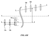
配向スロット130は、様々な異なる配列/構成を有することができる。図6Bを参照すると(そして図6Mを参照すると)、例えば、配向スロット130の中心が、累進軸C−Cから放射状に傾いている(例えば、支持構造122の長手方向軸B−Bの周りに約90°)配向軸D−Dに沿って配設され、間隔をあけて配置されている。配向軸D−Dは、長手方向軸B−Bに概ね平行に延在してもよく、あるいは長手方向軸B−Bに関して選択された角度で片寄っていてもよい(図6Nを参照して以下により詳細に記載される)。例示的実施形態において、配向スロット130の中心は、実質的に定間隔の配置として示されている。しかし他の実施形態において、個々のスロット130の間隔は、配向軸D−Dに沿って多様であってもよい。各スロット130は、長手方向軸B−Bの周りの最大弧長LLおよび長手方向軸B−Bの方向の最大スロット幅WWを画定する。
The
図6Bを参照すると、一実施形態において、配向スロット130は、長手方向軸B−Bの周りに様々な弧長LLのスロット群を含むことができる。例えば配向スロット130は、第一の弧長を有する第一の群の配向スロット130aと、第一の群の配向スロット130aの第一の弧長よりも短い第二の弧長を有する第二の群の配向スロット130bと、群130bの第二の弧長よりも短い第三の弧長を有する第三の群の配向スロット130cと、を含むことができる。例えば1つの特別な実施形態において、第一の群の配向スロット130aは、約0.038インチ(0.97mm)の弧長を有し、第二の群の配向スロット130bは、約0.034インチ(0.86mm)の弧長を有し、第三の群の配向スロット130cは、約0.03インチ(0.76mm)の弧長を有する。しかし別の実施形態において、配向スロット130は、互いに異なるサイズおよび/または配列を有していてもよい。例えば幾つかの実施形態において、配向スロットの1つ以上の群130は、異なるスロット幅(加えて、または代わりに、様々な弧長)を有していてもよい。
Referring to FIG. 6B, in one embodiment, the
一実施形態において、配向領域122bを画定するスロット130の総数は、20スロット未満であり(例えば、約5〜15スロット、約6〜12スロット)、配向領域122b全体に均等間隔で配置される。更に1つの特別な実施形態において、配向領域122bの総軸長は、約0.2〜0.25インチ(5.08〜6.35mm)である。別の実施形態において、配向領域122bは、異なる数のスロットおよび/または異なる配列および/または寸法を有していてもよい。
In one embodiment, the total number of
別の構成の配向スロットが、可能である。例えば再度、図6Iに示されたパターンを参照すると、配向スロット130’は、実質的に細長くてもよく、好ましくは長手方向軸B−Bの周りの最大弧長LL’および長手方向軸B−Bの方向の最大スロット幅WWを画定する。1つの特別な実施形態において、例えば各配向スロット130’は、約0.0005〜0.010インチ(0.01mm〜0.03mm)の範囲内の幅W’および約0.0005〜0.010インチ(0.01mm〜0.03mm)のスロット弧長LL’を有しているため、約7〜12mmの範囲内の非制限てき歪み状態での第一曲率半径rを画定する。しかし別の実施形態において、配向スロット130’は、別の寸法および/または配列を有していてもよい。
Alternative configurations of orientation slots are possible. For example, referring again to the pattern shown in FIG. 6I, the
例示的実施形態において、配向スロット130’は、配向軸D−Dに対して概ね垂直に延在し、配向軸D−Dを中心にして実質的に対称である。配向スロット130’は、概ね「I形状」であり、配向軸D−Dに対して垂直に延在する中央領域131aを有し、2つの拡大した側方領域131bが応力緩和のために中央スロット領域131aの周りに配設されている。この実施形態において、側方領域131bのそれぞれの周囲の長さを形成する支持構造122’’の壁が、例えば、支持構造122’’の長手方向軸B−Bに実質的に平行に延在する実質的に長方形の幾何学的配置を画定することができ、長方形の開口部の角は、半径をなしている(図示しない)。更に、個々の配向スロット130’の中央領域131aは、概ね長方形であってもよく、または別の適切な形状を有していてもよい。
In the exemplary embodiment, orientation slot 130 'extends generally perpendicular to orientation axis DD and is substantially symmetric about orientation axis DD. Orientation slot 130 'is generally "I-shaped" and has a
図61に示された配向スロット130’のそれぞれは、支持構造122の長手方向軸B−Bに実質的に垂直にその周りに延在する実質的に長方形の中央領域131aを含むことができる。中央領域131aの細長い側方壁が、その間に間隙を画定(例えば、約0.0015インチ(0.038mm))、構造122が歪んでいる間、スロットの最大の閉鎖間隙を定義する。各スロット130’は、長手方向軸B−Bの周りに配設されていて、中央領域131aと連通または隣接する側方領域131bも含むことができる。側方領域131bは、好ましくは支持構造122’’の長手方向軸B−Bに実質的に平行に延在する、実質的に長方形の幾何学的配置を画定して、長方形の開口部の角は半径をなして、応力緩和のための領域を画定している。実質的に長方形の側方領域131bの中心の間隔は、支持構造122’’の長手方向軸B−Bの周りに弧長L(例えば、約0.04インチ(1.02mm))を画定する。あるいは側方領域131bは、支持構造122、122’、122’’の長手方向軸B−Bに関して非垂直角の楕円形のカットとして形成されていてもよい。
Each of the
幾つかの実施形態において、配合領域内のスロット130’の総数は、概ね10スロット未満、例えば5スロットであり、スロット間隔は、例えば約0.03〜0.04インチ(0.76mm〜1.02mm)であってもよく、スロット130’は、等間隔で配置されていてもよい。更に幾つかの実施形態において、配向軸D−Dは、長手方向軸B−Bに概ね平行であってもよく、支持構造122’’の長手方向軸B−Bの周りに、例えば約0.01インチ(0.25mm)の最小弧長で約50°〜90°未満の範囲の角度で、累進軸C−Cから放射状に傾いていてもよい。
In some embodiments, the total number of
更に別の実施形態において、配向スロット130は、長手方向軸B−Bに関して実質的に傾いた配向軸に沿って配設されていてもよい。例えば図6Nは、該テクノロジーの別の実施形態により構成されたスロットパターンの平面図である。この実施形態において、配向スロット130は、例えば、約0度(0°)〜約45度(45°)の範囲内の角度θ2により長手方向軸B−Bに関して傾き得る配向軸D2−D2上に配設されている。角度のある配向軸D2−D2は、支持構造122の配備の際に先細の螺旋形幾何学的配置を有する配向領域122bを提供する。例えば図6Oは、患者の腎動脈内で配備状態にある、図6Nのスロットパターンを含む支持構造を有する処置デバイスの一部の略図である。
In yet another embodiment, the
可撓性/移行領域
再度、図6Aを参照すると、配向領域122bより近位に配設されているのは、可撓性または移行領域122cである。先に記載された通り、可撓性領域122cは、例えば長さ全体に可変的ピッチを有する移行性の螺旋形または渦巻状のスリットまたはカット132を含むことができる。可撓性領域122cの長さに沿って渦巻状のカット132の可変性ピッチが、支持構造122に、細長いシャフト116の長さに沿った可変的可撓性を提供する。例えば一実施形態において、移行性のカット132は、配向領域122bより近位で開始する例えば約170mmの軸長に延在する。しかし別の実施形態において、移行性のカット132は、異なる長さを有していてもよい。
Flexibility / Transition Region Referring again to FIG. 6A, it is the flexibility or
図6Cおよび6Dに示される通り、幾つかの実施形態において、移行性のカット132のピッチは、移行性のカットの長さ全体で多様であり、複数の異なる移行領域(図6Cでは4つの移行領域132a、132b、132c、および132dが示される)を画定してもよい。より具体的には一実施形態において、カット132は、例えば0.02インチ(0.51mm)の間隔で管状支持構造122の周りに5つの回転を形成することにより第一のピッチを有する第一の移行部分132aと、0.040インチ(1.02mm)の間隔の5つの回転により画定された第二のピッチを有する第二の移行部分132bまでの移行と、を画定する。カット132は引き続き、例えば0.06インチ(1.52mm)の間隔の10の回転により画定される第三のピッチを有する第三の移行部分132aと、0.08インチ(2.03mm)の間隔で20の回転により画定された第四のピッチまでの移行と、を画定する。先の例において、移行領域122cの先端から基端まで順番に各連続した移行部分132を考慮すると、スリットピッチの間隔が増加し、管状支持構造122の可撓性が低下することが、理解されなければならない。
As shown in FIGS. 6C and 6D, in some embodiments, the pitch of the
移行性のカット132は、その長さ全体で、例えば約0.0005インチ(0.01mm)の、概ね一定した幅を有していてもよく、または移行性のカット132の幅は、長さ全体で多様であってもよい。移行性のカット132は、各端部に、移行性のカットと隣接または連通した実質的に円形の空隙を含むこともできる。しかし別の実施形態において、移行性のカット132は、異なる配列および/または異なる寸法を有することができる。例えば、移行性のカット132は、ピッチの段階的増加を有するというよりむしろ、移行領域122cの先端から基端まで連続して増加するピッチを有していてもよい。
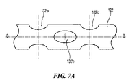
The
別のスロット、カットおよび/または開口部の構成により、移行性のカット132の代わりに可撓性領域122cの所望の可撓性、応力緩和または他の性能特性を提供することができる。例えば幾つかの実施形態において、開口部または穴は、細長いシャフト116内に選択的に形成されて、所望の可撓性を提供してもよい。可撓性領域122cの個々の開口部または穴は、例えば支持構造122の中心の長手方向軸B−Bに平行に延在する軸に沿って配設された中心を有することができる。例えば図7Aおよび7Bは、それぞれが管状支持構造122を通って延在するスルーホールまたは開口部132’a、132’b、132’cを有する可撓性領域122cの別の配列を有する支持構造122を示す。例えば開口部132’は、支持構造122の長手方向軸B−Bの周りに互いに軸上に間隔をあけて角度をつけて軸上に交互に配設させることができる。例示的実施形態において、例えば開口部132’bは、軸上に隣接する開口部132’aおよび132’cに関して90°に角度をつけて配設されている。しかし別の実施形態において、開口部132’は、異なる配列を有していてもよい。
Alternative slot, cut and / or opening configurations may provide the desired flexibility, stress relief or other performance characteristics of the
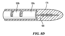
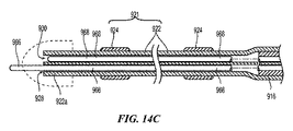
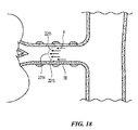
図8Aは、管腔内の標的処置部位で治療または処置アセンブリ121の送達および配備のため、そして特に腎動脈内で腎除神経を実施するために、支持構造122を有する先端領域120を有する細長いシャフト116を有するカテーテルを含む処置デバイス100の一部区分の分解斜視図である。細長いシャフト116の基端に配置されているのは、細長いシャフト116および治療アセンブリ121の操作のための、略図で示されたハンドルアセンブリ134である。より具体的にはハンドルアセンブリ134は、送達状態と配備状態の間で治療アセンブリ121を制御または変換するための制御部材168(例えば、制御ワイヤ)の遠隔操作を提供するように構成されている(図8Aに示す)。
FIG. 8A is an elongate having a
システム100は、治療アセンブリ121を送達状態にある処置部位に送達されるように構成されており(図示しない)、治療アセンブリ121は実質的に線状(例えば、直線)であるため、エネルギー送達要素124は、支持部材122に沿って実質的に軸上に心合わせされている。エネルギー供給ワイヤ25は、支持部材122の外表面に沿って配設されていてもよく、処置エネルギーを各エネルギー送達要素124に供給するために、エネルギー送達要素124のそれぞれに結合されていてもよい。腎動脈内の処置部位に配置されると、送達状態から配備状態に治療アセンブリ121を変換する制御部材168の動作が、示される。例示的実施形態において、制御部材168は、管状支持構造122内に配設されている。制御ワイヤ168の一方の端部は、支持構造122の先端126aまたはその付近に付着されていてもよい(例えば、チップ部材174で終結している)。制御部材168の反対側の端部は、ハンドルアセンブリ134内で終結していてもよく、送達状態と配備状態の間で治療アセンブリ121を変換するアクチュエータに、動作可能に結合されている。
Since the
制御ワイヤ168の張力が、支持構造122の先端126aに近位方向および/または軸方向の力を提供することができる。例えば、制御部材168における張力の影響下で、支持構造122の遠位領域122bは、歪む。遠位の歪み領域122aは、好ましくは複数のスロット128を含む(2つのみを128’aおよび128’bとして示す)。先に記載された通り、スロット128’aおよび128’bは、累進軸に沿って配設されている。支持構造の遠位領域122aにおいて形成されたスロット128’aおよび128’bは、先端領域122aの歪みを傾かせて、1つ以上の屈曲部分を形成しており、それぞれが好ましくは歪みスロット128の数、個々のスロット幅、スロット構成、および/またはスロット配列により画定された、曲率半径を有する。先端領域122aが連続して歪んでいるため、それは放射状に延在して、1つ以上の間隔のあいたエネルギー要素124を腎動脈の内壁55と接触して配置する。支持構造122は、制御ワイヤ168の張力および血管壁55の放射状制限を受けると、実質的に螺旋形を形成して、エネルギー送達要素124を互いに軸上に間隔をあけて配置し、放射状に傾くように構成されている。その上、支持構造122の歪み領域122aは、張力負荷の下で、腎動脈内の螺旋形の幾何学構造を形成するように構成されているため、処置アセンブリ121は、腎動脈壁55を放射状に過剰負荷することは予測されない。むしろ、支持構造122が変形して、張力負荷を連続的に増加させながら螺旋を形成する。
The tension of the
先に議論された通り、歪みスロット128、128’、128’’が配設された軸(例えば、累進軸C−C)の累進角度は、得られた配備配列の螺旋角度を画定する。一実施形態において、治療アセンブリ121を完全に配備する張力の量は、典型的には治療アセンブリ121の先端126aに負荷される約1.5lbf(重量ポンド)未満(0.68kgF)、例えば約1lbf(0.45kgF)〜約1.5lbf(0.68kgF)である。図8Aの螺旋形の配備状態において、スロット128’は、螺旋の外表面に配設されたエネルギー送達要素24のための供給ワイヤ25と共に内表面に沿って配設されて、アセンブリの「とげ」を形成する。供給ワイヤ25は、処置デバイス112の長さに沿って適宜構成されたエネルギー発生装置(図示しない)まで伸長することができる。
As discussed above, the progressive angle of the axis (eg, progressive axis CC) in which the
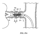
治療アセンブリ121の支持構造122は、治療アセンブリを腎動脈壁に隣接して配置させるために、アセンブリの配向領域122bを画定する基端部分を含む。図8Aに示す通り、支持構造122の近位領域は、複数の配向スロット130’を含む。操作において、張力の下で制御ワイヤ168を配置するハンドルアセンブリ134の動作時に、配向領域122bは、腎動脈内で放射状に外方向に歪んで、治療アセンブリ121を動脈壁55に接触して配置する。より具体的には、スロット130’は、張力の下で変形して、支持構造122の長手方向軸B−Bから放射状に外側に配向領域122bを歪ませる。完全に配備された状態において、支持構造122の先端の治療アセンブリ121の得られた螺旋形の幾何学的配置は、好ましくは支持構造122の基端の長手方向軸B−Bから傾いているため、支持構造122の螺旋軸H−Hと長手方向軸B−Bとは、非同軸上にある。軸H−H、B−Bは、互いに平行であってもよく、あるいは互いに傾いていてもよい。
The
支持構造122の基端は、分離した部材に結合してデバイス112の細長いシャフト116を形成することができる。あるいは支持構造122および細長いシャフト116は、先端126aから近位にハンドルアセンブリ134内まで延在する1つの単位部材であってもよい。一実施形態において、管状の支持構造122は、金属製の形状記憶材料(例えば、ニチノール)で形成されている。更に一実施形態において、支持構造122は、5インチ(12.7mm)未満、より具体的には約2インチ(5.08cm)の軸長;0.020インチ(0.57mm)、より具体的には約0.016インチ(0.41mm)〜約0.018インチ(0.46mm)の範囲内の外径;0.005インチ(0.13mm)未満、より特別には約0.003インチ(0.08mm)の管状壁圧を有することができる。複数の実施形態において、細長いシャフト116は、例えば約0.020(0.57mm)〜約0.060インチ(1.52mm)、の外径を有するステンレス鋼金属の管から形成することができる。近位の支持構造122を細長いシャフト116に結合させる際に、ジョイント119が、それらの間に提供されていて、処置部位に誘導する際に細長いシャフト116から支持構造122への所望のトルク移動を提供してもよい。より具体的には、支持構造122および細長いシャフト116の各端部は、それぞれ、ジョイントアセンブリ120に示された通り管状部材の端部を互いに連動させる嵌合ノッチ(mating notch)を含んでいてもよい。幾つかの実施形態において、ジョイント119の周りに配設されるのは、接合点の周りに圧着させてジョイント119に追加の指示を提供する、ステンレス鋼スリーブである。
The proximal end of the
先に記載された通り、制御部材168は、支持構造122の先端126aまたはその付近からハンドルアセンブリ134までのカテーテルデバイス112の軸長を伸長する制御ロッドまたはワイヤであってもよい。制御ワイヤ168は、超高分子量(UHMW)繊維、例えば商標SPECTRAという高強度のジェルスパンファイバーソリッドまたは他の十分に強いポリエチレンファイバーで構成されていてもよい。あるいは、その適用法と適合性があり、処置デバイス112の長さ全体で治療アセンブリ121の先端への張力を移行させ得ることが前提であれば、ニチノール、商標KEVLARというパラアラミド合成ファイバーソリッド、または他のモノもしくはマルチフィラメントタイプを用いることができる。
As previously described, the
治療アセンブリ121の先端に所望の張力を提供するために、制御ワイヤ168は、支持構造122の先端126aまたはその付近に固着されていてもよい。例えば図8B〜8Dは、制御ワイヤ168のための様々な固着構成を示す。より具体的には図8Bに示される通り、支持構造の先端126aは、制御ワイヤ168を結んで固着する軸上開口部に隣接するスロットを含む。図8Cに示された別の固着配列において、制御ワイヤ168は、先端126aの軸上開口部を通して伸長する。制御ワイヤ168は、コイル174材料内にくるまれていて、支持構造122の近位から先端部分にスライドさせることにより制御ワイヤ168を停止させる。図8Dは、本開示の実施形態により構成された別のチップ174を示す。この配列において、制御ワイヤ168は、3重に結ばれていて、チップの中に形成されているポリマー材料をコーティングした制御ワイヤ168の表面の拡大を提供する。
The
再度、図8Aを参照すると、制御ワイヤ168は、細長いシャフト116を通ってハンドルアセンブリ134まで伸長する。治療アセンブリを配備状態と送達状態の間で変換する時に、制御ワイヤ168を引っ張る、そして緩めるハンドルアセンブリ134の操作において、移動する制御ワイヤ168と比較的静止した細長いシャフトの内部の間に、摩擦が生じる。制御ワイヤ168の組み立ての一実施形態は、制御ワイヤ168と細長いシャフト116の内部の間の摩擦接触を最小限にするように構成される。例えば、図8Aに示される通り、スリーブ170を配設し、制御ワイヤ168に結合させて、比較的低摩擦の外表面を提供することができる。スリーブ170は、好ましくは細長いシャフト116の軸長よりも短い軸長を有し、より好ましくは細長いシャフト116内の制御ワイヤ168の実質的に基端の部分を覆う。制御ワイヤ168を引っ張る、そして緩めるハンドルアセンブリ134の操作の間に、管状スリーブ170が、制御ワイヤ168と共に移動するように構成されていて、細長いシャフト116の内部に対するベアリング表面として作用し、それにより制御ワイヤ168と細長いシャフト116の間の摩擦を軽減する。
Referring again to FIG. 8A, the
複数の実施形態において、制御部材は、エネルギー送達要素を運搬する処置アセンブリの支持構造の外側になるように構成されていてもよい。例えば処置アセンブリの支持構造は、代わりに、制御部材の外側に巻き付けられていても、またはその周りをくるまれていてもよい。そのような配列において、制御部材は、支持構造の一部に係合して、支持構造および処置アセンブリを送達状態と配備状態の間で転換する力を加える。 In embodiments, the control member may be configured to be outside the support structure of the treatment assembly that carries the energy delivery element. For example, the support structure of the treatment assembly may instead be wrapped around or wrapped around the control member. In such an arrangement, the control member engages a portion of the support structure and applies a force that switches the support structure and treatment assembly between a delivery state and a deployed state.
例えば図9Aおよび9Bは、本発明のテクノロジーの更なる実施形態により構成された処置デバイス212の先端部分を示す。より具体的には図9Aおよび9Bは、支持構造222の周りに配設された複数のエネルギー送達要素224で制御部材268の周りを螺旋形にくるまれた管状支持構造222を有する処置アセンブリ221を示す。支持構造222は、先に記載された支持構造22および122と概ね類似した複数の特色を含むことができる。
For example, FIGS. 9A and 9B show a distal portion of a
例示的実施形態において、支持構造222の先端領域または部分222aは、端部の部品(例えば、円錐または銃弾形チップ250)、あるいは環、シャフト、またはキャップで終結する。チップ250は、丸まった先端部分を含み、処置デバイス212の腎動脈への非侵襲的挿入を容易にすることができる。支持構造222の近位領域または部分222bは、処置デバイス212の細長いシャフト216に結合および付着されている。細長いシャフト216は、制御部材268の通過のための中心通路を画定する。制御部材268は、細長いシャフト216から伸長して、チップ250で支持構造222の遠位領域222aに付着されている。その上、制御部材268は、細長いシャフト216の中をハンドルアセンブリ234内のアクチュエータ236まで滑動可能に通過する。
In the exemplary embodiment, the tip region or
この実施形態において、制御部材268は、細長いシャフト216を遠位および近位方向へ移動し、それに応じて支持構造222の遠位領域222aを移動させるように構成されている。遠位領域222aの遠位および近位方向への移動は、それぞれ支持構造222の螺旋の軸長を延長および短縮して、送達状態(図9B)と配備状態(図9A)の間で処置アセンブリ221を変換することで、エネルギー送達要素224が放射距離Yを移動して、腎動脈壁に係合する(図示しない)。
In this embodiment, the
別の実施形態において、処置アセンブリは、管状支持構造の先端領域で制御部材に付着されていなくてもよい。例えば図9Cは、螺旋形の支持構造222の周りに配設された複数のエネルギー送達要素224を含む螺旋形支持構造222を有する処置デバイス212’および処置アセンブリ221’の別の実施形態を示す。支持構造222の先端領域222aは、端部部品250で終結している制御部材268を滑動可能に収納するサイズおよび形状の通路を含む環状要素274に結合されている。この実施形態において、制御部材268は、細長いシャフト216から伸長する制御ワイヤを含み、細長いシャフト216および環状要素274を通って遠位および近位方向へ移動する。停止部材275は、環状要素274よりも近位で制御ワイヤ268に結合させることができる。
In another embodiment, the treatment assembly may not be attached to the control member at the distal region of the tubular support structure. For example, FIG. 9C illustrates another embodiment of a
制御ワイヤ268は、螺旋形支持構造222を短縮または延長するために引く、または押すと、螺旋形支持構造222の展開および/または収縮を容易にする。例えば制御ワイヤ268を引くと(即ち、張力の増加)螺旋構造222の展開が誘発されてもよく、制御ワイヤ268を押すと(即ち、圧縮力の増加)螺旋形支持構造222を圧縮構成まで延長してもよい。幾つかの実施形態において、螺旋構造222は、弾性または超弾性を有するため、力を抜くと、螺旋構造222が弾性により緩めた状態に戻る。力が端部部品250または停止部材275により加えられて、処置アセンブリ221’を送達状態と配備状態の間で変換してもよい。例えば制御ワイヤ268が遠位方向へ押されて、停止部材275が環状要素274と係合してそれを遠位方向へ移動させて、支持構造222を延長して径を減少させ、それを送達状態で配置させる。あるいは制御ワイヤ268が、近位方向へ引かれて、端部部品250に環状要素274と係合させ、近位方向へ移動させることで、螺旋形支持構造222を短縮してその径を増加させ、それによりそれを配備状態で配置させてもよい。
The
螺旋形支持構造222が、プリフォームされた螺旋形の形状記憶を有する場合には、環状要素274が停止部材275または端部部品250と係合していなければ、螺旋形支持構造222が、弾性によりプリフォームされた形状まで展開する。このようにして螺旋形支持構造222は、比較的一定した力で、腎動脈の内壁に接触するように展開してもよい。更に幾つかの実施形態において、プリフォームされた螺旋形構造222により腎動脈内で発揮された力が、ハンドルアセンブリ234でオペレータの制御にあまり依存していなくてもよい(図9A)。
If the
図9Dおよび9Eは、処置デバイス212’’の別の実施形態を示す。この実施形態において、制御部材268’は、ガイドワイヤ266のための内部通路を画定する中空管を含み、腎動脈への血管内進路を通した処置アセンブリ221の挿入を容易にする。したがって処置デバイス212’’は、本明細書に記載されたOTWまたはRT送達のために構成されている。制御部材268’は、制御部材を通して延在し、例えば約0.003インチ(0.08mm)未満(例えば、約0.001インチ(0.02mm))の壁厚を有するポリイミド管、および約0.015インチ(0.38mm)未満(例えば、約0.014インチ(0.36mm))未満の径を有する管腔で構成された内部管腔を画定する。デバイス212’’は、ガイドワイヤ266を係合し、それに沿って追跡することに加えて、図9Aおよび9Bに関して図示および記載された処置デバイス221のものと類似の手法で、送達状態と配備状態の間で処置アセンブリ212の構成を変換する。
Figures 9D and 9E show another embodiment of a
図10Aおよび10Bは、OTW構成を有し、管状制御部材368を含んで、処置デバイスの実質的に全長に延在するガイドワイヤ管腔を画定する、処置デバイス310の別の実施形態の側面図である。制御部材368は、ガイドワイヤ366を滑動可能に収容することで、処置デバイス310がオーバーザワイヤ技術を利用してガイドワイヤ366を追跡し得るように構成されている。制御部材368は、細長いシャフト316内に滑動可能に配設されている。一実施形態において、制御部材368は、熱または接着剤での結合方法を利用して、細長いシャフト316の内表面に付着された薄壁のスリーブ(図示しない)内の細長いシャフト316に関して滑動させることができる。薄壁のスリーブは、非限定的にポリイミドなどのポリマー材料から形成されていてもよい。しかし別の実施形態において、処置デバイス310が、スリーブを含んでいなくてもよい。
10A and 10B are side views of another embodiment of a
処置デバイス310は、細長いシャフト316の先端部分と制御部材368の先端部分との間を伸長する処置アセンブリ312も含む。処置アセンブリ312は、脈管構造内の標的位置に配備可能であり、エネルギー発生装置326からのエネルギーを血管壁に送達する複数の(例えば、6つの)エネルギー送達要素324(例えば、電極)を含む。幾つかの実施形態において、エネルギー送達要素または電極324は、支持構造322の長さに沿って等しい間隔で配置されていてもよい。しかし別の実施形態において、エネルギー送達要素324の数および/または配列が、多様であってもよい。支持構造322の軸長は、例えば約17mm〜20mmの間であってもよい。しかし別の実施形態において、支持構造322は、該構造が所望の電極間隔パターンで複数の電極を十分に支持する限りは、異なる長さを有していてもよい。
The
エネルギー送達要素324は、支持構造322に沿って間隔をあけて配置された、一連の分離した帯状電極であってもよい。帯状または環状電極は、例えば円板または平板電極に比較して、アブレーションに低電力が必要となるため、幾つかの実施形態において用いられてもよい。しかし他の実施形態において、円板または平板電極も、使用に適している。更に別の実施形態において、渦巻またはコイルの形状を有する電極が、用いられてもよい。一実施形態において、個々のエネルギー送達要素324は、およそ1〜5mmの範囲内の長さを有していてもよく、エネルギー送達要素324のそれぞれの間隔は、およそ1〜10mmの範囲内であってもよい。しかし他の実施形態において、エネルギー送達要素324は、異なる寸法および/または配列を有していてもよい。
The
エネルギー送達要素324は、任意の適切な金属材料(例えば、金、プラチナ、プラチナとイリジウムとの合金など)から形成されていてもよい。例えば一実施形態において、エネルギー送達要素324は、純金99.95%で、約0.025インチ(0.64mm)〜0.030インチ(0.76mm)の範囲内の内径、および0.030インチ(0.76mm)〜0.035インチ(0.89mm)の範囲内の外径を有していてもよい。より小さなまたは大きな寸法、即ち、径および長さの電極も、本明細書における使用に適している。
The
各エネルギー送達要素または電極324は、細長いシャフト316の管腔を通して伸長する伝導体またはワイヤ(図示しない)により発生装置326に電気的に連結されている。各電極324は、エネルギー供給ワイヤの先端に溶接または他の方法で電気的に結合されていてもよく、各ワイヤは、細長いシャフト316の長さ全体で該シャフトを通って伸長することで、その基端が発生装置326に結合することができる。
Each energy delivery element or
支持構造322は、少なくともアセンブリ312の長さを伸長する形状記憶の構成要素を含んでいてもよい。形状記憶支持構造322を用いて、図10Aに示された送達状態(即ち、実質的に直線形態)から、図10Bに示された配備状態(即ち、事前設定された渦巻または螺旋形態)まで処置アセンブリ312を配備または変換する。より具体的には、支持構造322の形状記憶構成要素は、配備状態にプリフォームまたは予備成形された形状記憶材料から構築されていてもよい。特定の形状記憶材料は、特定の熱条件に供されると、事前画定または事前決定された形状に戻す能力を有する。形状記憶材料、例えばニッケル−チタン(ニチノール)または形状記憶ポリマーもしくは電場応答高分子が、比較的適温である場合、それから形成された物品は、一般に、ここの実施形態では37℃の正常な体温を超える、比較的高い変態温度に暴露されて、その後、変態前に保持した事前画定または事前決定された形状に戻るまで、それらが保持する新しい形状に極めて容易に変形することができる。幾つかの実施形態において、支持構造322は、そのような形状記憶材料から形成され、変形された低プロファイルの直線状態で体内に挿入され、形状記憶支持構造322がインビボで変態温度に暴露されると、「記憶されていた」事前設定形状に戻ってもよい。つまり形状記憶支持構造322は、少なくとも2段階のサイズまたは形状、つまり図10Aに示された通り処置部位に送達されるための十分に低プロファイルの概ね直線または引き伸ばされたコイル構成と、図10Bの破線で示された、エネルギー送達要素324を血管壁55と接触して配置する渦巻または螺旋構成と、を有する。配達状態を得るために、状態記憶支持構造を操作者又はテンション機構によって使って機械的に歪を取ってもよい。図10Aを参照すると、一実施形態において、形状記憶支持構造322の送達径D1は、標的血管、例えば腎動脈への送達に適合するために約1〜2mmであってもよい。
処置アセンブリ312は、エネルギー送達要素324から形状記憶支持構造322を電気的に絶縁するよう機能する絶縁性構成要素(図示しない)を含んでいてもよい。例えば絶縁性構成要素は、電気絶縁性材料、例えばポリエチレンブロックアミドコポリマーから形成された管腔を画定する環状シースを含むことができる。実施形態において、絶縁性構成要素は、およそ0.027インチ(0.69mm)の外径、およびおよそ0.023インチ(0.59mm)の内径を有していてもよい。絶縁性構成要素は、形状記憶支持構造322および収納ワイヤを収納して、追加の保護を提供するように構成されており、電極324は、絶縁性構成要素に付着されているか、またはその周りに配設されている。絶縁性構成要素の先端は、接着剤、スリーブ、または他の機械的方法などの任意の適切な方法により、ガイドワイヤシャフト368の先端に付着されていてもよい。図10Aに示された一実施形態において、絶縁性構成要素の先端は、好ましくはシアノアクリラート接着剤によりガイドワイヤシャフト368の先端に付着されており、ポリマースリーブは、先端を取り囲んでまとめ、処置アセンブリ312の先細の先端チップ350を形成している。しかし他の実施形態において、絶縁性構成要素は、処置アセンブリ312に関して異なる配列を有していてもよい。
形状記憶支持構造322および絶縁性構成要素の両方が、好ましくは長さ処置アセンブリ312の長さに沿って延在し、近位からシャフト316の先端に、少なくとも1または2センチメートル延在するため、形状記憶支持構造322の基端は、エネルギー送達要素324から十分に除去されて、任意の熱作用が回避される。
Both the shape
処置アセンブリ312の形状記憶支持構造322が、配備構成であると仮定すると、絶縁性構成要素の先端は、内部管状シャフト368の先端に結合されているため、絶縁性構成要素の先端が、近位方向に後退することで、処置アセンブリ312が血管壁と接触しながら放射状に展開する。制御部材368も、処置アセンブリ312の配備を可能にするために、細長いシャフト316内をわずかに近位に後退させる。
Assuming that the shape
処置または治療デバイスのこれまで記載された実施形態のそれぞれにおいて、制御部材は、支持構造の先端またはその付近に力を加えて送達状態と配備状態の間で治療アセンブリの構成を変化させる、ワイヤ、管状シャフトまたは他の内部部材として構成される。しかし他の実施形態において、動作の力を治療アセンブリの基端またはその付近に加えて、アセンブリの構成を変換してもよい。 In each of the previously described embodiments of the treatment or therapy device, the control member applies a force to or near the tip of the support structure to change the configuration of the therapy assembly between the delivered state and the deployed state; Configured as a tubular shaft or other internal member. However, in other embodiments, a force of motion may be applied at or near the proximal end of the treatment assembly to change the configuration of the assembly.
例えば図11Aおよび11Bは、処置アセンブリの基端に変形力を加えるように構成された処置デバイス612の実施形態を示す。処置デバイス612は、ハンドルアセンブリ634に結合された基端と、処置アセンブリ621に結合された先端とを有する管状の細長いシャフト616を含む。例示された処置アセンブリ621は、複数のエネルギー送達要素624を運搬する管状支持構造622を含む。エネルギー供給ワイヤ(明確にするために省略)が、支持構造622に沿って内側または外側から伸長して、処置エネルギーをエネルギー送達要素624に提供する。支持構造622の基端622bは、管状の細長いシャフト616の先端内に配設され、そこに付着されている。支持構造622は、好ましくは、処置アセンブリ621を超えて遠位から、そしてハンドルアセンブリ634を超えて近位から伸長し得るガイドワイヤ666の通過のために内部管腔を有する管状制御部材668の周りをくるまれた螺旋形状を画定する。したがって処置デバイス612は、オーバーザワイヤ送達のために構成されている。支持構造の先端622aは、管状制御部材668の遠位領域に結合されている。制御部材668は、近位から細長いシャフト616内へ伸長して、ハンドルアセンブリ634の内表面に付着される。したがって支持構造622の先端622aは、ハンドルアセンブリ634から一定距離を維持していてもよい。
For example, FIGS. 11A and 11B illustrate an embodiment of a
細長いシャフト616は、近位からハンドルアセンブリ634に伸長して、アクチュエータ636に結合される。一実施形態において、アクチュエータ636は、細長いシャフト616の線状の交換または直接長手方向の移動を提供する。アクチュエータ636は、スライダーイングルーブ(slider−in−groove)アセンブリとして略図で示されている。操作において、アクチュエータ636の近位移動は、軸上のシャフト616をハンドルアセンブリ634に関して近位に、つまり内部部材668に移動させる。細長いシャフト616の先端は、支持構造622の付着された基端622bに張力を加える。支持構造622の先端622aは、制御部材668に付着されているため、支持構造622の基端622aの近位移動は、該構造を伸長して、処置アセンブリ612を低プロファイル送達状態で配置させる(図11A)。アクチュエータ636の遠位移動によって、支持構造622が軸上に圧縮されて、処置アセンブリ612を配備状態で配置させる(図11Bに最良に見られる)。
An
ハンドルアセンブリ634の別の構成は、細長いシャフト616の所望の軸上移動を提供することができる。例えば図11Cは、細長いシャフト616を軸上に移動させる蝶番タイプのアクチュエータ636’を提供するハンドルアセンブリ634の別の配列を示す。アクチュエータ636’は、細長いシャフト616への蝶番連結を含むことができる。したがって蝶番連結の周りのアクチュエータ636’の角回転(angular rotation)は、細長いシャフト616を線状に移動させる。アクチュエータ636’の角回転の量は、細長いシャフト616と蝶番点の間の距離により制御することができる。図11Dは、細長いシャフト616を線状に移動させるギアタイプのアクチュエータ636’’を含むハンドルアセンブリ634の別の代替的構成を示す。例えば一実施形態において、アクチュエータ636’’は、小さなギアに連結されたノブまたはサムローラを含む。細長いシャフト616は、小さなギアに係合されたより大きなギアに連結していているため、小さなギアが回転すると、その一方で大きなギアを回転させて、細長いシャフト616を移動させてもよい。ギアサイズの差により、小さなローラの回転が細長いシャフト616の大きな移動を作り出すことができる。
Another configuration of the
処置デバイスのこれまで記載された実施形態において、該デバイスの処置アセンブリは、構成に応じて支持構造の基端または先端のいずれかを押す、または引くことにより、送達状態と配備状態の間で変化した。処置デバイスが、支持構造の基端または先端のいずれかで、またはその付近で選択的に力を加えることで、例えば支持構造の周りの制限に応じて、医師が関連の移動の端部を選択してもよいことを、理解しなければならない。 In the previously described embodiments of the treatment device, the treatment assembly of the device changes between a delivery state and a deployed state by pushing or pulling either the proximal or distal end of the support structure, depending on the configuration. did. The treatment device selectively applies force at or near the proximal or distal end of the support structure, allowing the physician to select the end of the associated movement, for example, depending on restrictions around the support structure You must understand what you can do.
複数の別の構成において、処置アセンブリは、制御部材(例えば、挿入部材、探査針、予備成形部材など)を管状支持構造の遠位処置区分または部分に挿入する、または後退させることにより、送達状態と配備状態の間で可動性にすることができる。例えば図12Aおよび12Bは、該テクノロジーの追加の実施形態により構成された処置デバイス700の一部の側面斜視図である。より具体的には図12Aは、患者の体外の送達状態(例えば、低プロファイルまたは折り畳み構成)にある処置デバイス700を示し、図12Bは、配備状態(例えば、展開構成)にある処置デバイス700を示す。図12Aおよび12Bを一緒に参照すると、処置デバイス700は、先端部分702を有する細長いシャフト701と、先端部分702の処置区分704とを含む。処置デバイス700は、処置区分704により運搬される複数のエネルギー送達要素706も含む。処置デバイス700は、処置デバイス700に結合されていて、処置区分704に関して滑動可能に可動性である制御部材708(破線で概略的に示す)を更に含む。以下により詳細に記載する通り、処置区分704または制御部材708は、プリフォームの螺旋形状を含み、処置区分704および制御部材708の他方は、実質的に直線形状を含む。処置区分704および制御部材708は、互いに関して可動性であり、低プロファイル送達状態(図12A)とプリフォームの螺旋形状を有する展開状態(図12B)の間で処置デバイス700を変化させる。例示の目的で、制御部材708は、図12Aおよび12Bの両方において示される。以下により詳細に記載される通り、様々な実施形態において、制御部材708は、処置区分704に挿入するか、またはそこから引き出されて、送達状態と配備状態の間で処置デバイス700を変化させてもよい。
In a plurality of alternative configurations, the treatment assembly is delivered by inserting or retracting a control member (eg, insertion member, probe needle, preformed member, etc.) into a distal treatment section or portion of the tubular support structure. And can be mobile between deployed states. For example, FIGS. 12A and 12B are side perspective views of a portion of a
例えば、以下に記載された一実施形態において、制御部材708は、探査針、硬化マンドレル、引き伸ばし部材、または処置上のガイドワイヤを含むことができ、処置デバイス700の長さの少なくとも一部に沿って伸長し、送達の間に処置デバイス700の予備成形された螺旋処置区分704を直線化するように構成させることができる。より具体的には、制御部材708は、制御部材708が処置区分704に関してそれぞれ引っ張る、または押すと、処置区分704の展開および/または収縮を容易にする。別の実施形態において、予備成形された制御部材(例えば、探査針または予備成形部材)は、処置デバイス700の比較的可撓性の先端部分702に螺旋形状を提供することができる。
For example, in one embodiment described below, the
図13A〜15Bは、図12Aおよび12Bに関して先に記載された処置デバイス700と概ね類似した特色を含む処置デバイスの様々な実施形態を対象とする。例えば図13Aおよび13Bは、中央管腔729を画定する比較的可撓性の管状支持構造722により運搬される複数のエネルギー送達要素724を有する処置区分またはアセンブリ721を含む処置デバイス712の断面図である。管状支持構造722は、管腔729を通って伸長するガイドワイヤ766(図13A)の通過のための軸上開口部を有する先端722aを含む。管状支持構造722は、管状の細長いシャフト716の先端に結合または付着された基端722bを有する。細長いシャフト716は、ガイドワイヤ766を収納するための中央管腔を画定する。したがって本発明の構成は、ガイドワイヤ766が最初に挿入されるアクセス部位から処置部位(例えば、腎動脈内)までのオーバーザワイヤ送達を提供し、処置デバイス712は、ガイドワイヤ766に設置される。可撓性管状支持構造722を通して実質的に直線の線状ガイドワイヤ766を挿入することで、腎動脈内の処置部位への送達のために、管状支持構造722を法線方向に直線形状を保持して、処置アセンブリ721を低プロファイルの送達状態に配置する。ガイドワイヤ766は、長さに沿って一定の剛性であってもよく、または例えば近位から遠位の方向へ、高い可撓性を提供するように、長さに沿って可変的な剛性もしくは可撓性を有していてもよい。
13A-15B are directed to various embodiments of treatment devices that include features generally similar to the
処置デバイス712が、ガイドワイヤ766上を腎動脈内の所望の位置まで送達されると、ガイドワイヤ766が、処置デバイス712から完全に後退させて、細長い制御部材768(図13B)が、デバイス712の基端から挿入されて、細長いシャフト716を通して遠位方向へ管状支持構造722の中央管腔729まで進行させる。制御部材768の遠位領域は、処置アセンブリ721の配備状態を画定するよう制限されていない場合には、事前設定された配備形状(例えば、螺旋形状)を有することができる。制御部材768は、事前設定またはプリフォームされた螺旋形状を有する超弾性ニチノール材料から製造されていてもよい。あるいは制御部材は、形状記憶材料から製造させることができる。
When the
制御部材768は、例えばハンドル734で、デバイスの基端での挿入のために直線化されるのに十分に弾性である。制御部材768は、細長いシャフト716に直接挿入されてもよい。あるいは制御部材768は、最初、より剛直な挿入管769(図13B)の内側に収納され、制御ワイヤ768を直線化して、カテーテルデバイス712への制御部材768の挿入を容易にしてもよい。この実施形態において、処置アセンブリ721は、細長いシャフト716の基端に挿入することができ、腎動脈内の処置部位に配置されると、挿入管769を後退させて、制御部材768を配備させることができる。図13Bに示された通り、制御部材768は、管状支持構造722に力を加え、それによりそれを展開された螺旋構成に変形させて、処置アセンブリ721を配備させ、エネルギー送達要素724を腎動脈壁に接触させて配置させる。
The
具体的な実施形態において、複数の電気送達要素724が、可撓性で幾分か膨張性の管722(例えば、PEBAX(登録商標)5533Dなどのポリエチレンブロックアミドコポリマー、または低ジュロメータ材料で製造された管)に搭載されたマルチ電極724として構成される。別の実施形態において、管状支持構造722は、他のポリマー、例えば所望の可撓性を提供するPET、ポリアミド、ポリイミド、PEBAX、ポリプロピレン、またはPEEKポリマーから構築されていてもよい。一実施形態において、管状支持構造722は、約0.03インチ(0.76mm)の内径および約0.04インチ(1.02mm)の外径および約4cmの長さを有する。電極724は、円筒状電極であってもよく、一実施形態において、約0.042インチ(1.07mm)の内径、約0.046インチ(1.17mm)の外径、および約1mmの長さを有することができる。電極724は、3〜5mm離れて配置されていて、接着剤を用いて管状支持構造722に結合されていてもよい。電極の導電性電力供給ワイヤ725が、管状支持構造722に沿って近位からその外側に伸長することができる。
In a specific embodiment, the plurality of
複数の実施形態において、電極724を有する可撓性支持構造722の基端722bは、管状の細長いシャフト716の先端に配置され、適所に結合されている。例えば細長いシャフト716は、ポリアミド管を含むことができる。一実施形態において、シャフト716は、約0.025インチ(0.64mm)の内径および約0.03インチ(0.76mm)の外径と、約100cmの長さを有する。別の実施形態において、細長いシャフトは、0.026インチ(0.66mm)の内径および0.028インチ(0.71mm)の外径、ならびに/または他の適切な寸法を有する。外部管状ジャケット717が、シャフト716を取り囲んでいてもよく、管状支持構造722の基端722aに隣接または重複することができる。
In embodiments, the proximal end 722b of the flexible support structure 722 with the
処置アセンブリ721を配備するための制御部材768は、例えば制御部材768の先端領域に、螺旋構成に予備成形されたニチノールワイヤを含むことができる。一実施形態において、制御部材768は、約0.015インチ(0.38mm)の径を有し、0.008インチ(0.20mm)の径を有するチップまで遠位方向に先細になっている。予備成形された制御部材768の複数の異なる径は、異なる径の腎動脈を収納するように製造することができ、それぞれが約4.0mm〜約8.0mmの範囲内の径を有することができる。制御部材768は、体温をわずかに超える形状記憶変態温度(例えば、オーステナイトの終了温度Af=42℃)を有することができる。制御部材768は、Af未満の温度ではより柔軟であり、それゆえ螺旋領域は、比較的容易に手で直線化することができる。したがってその後、制御部材768は、「剛直な挿入管769」を必要とせずにカテーテルの基端に直接挿入することができる。制御部材768の先端領域が、マルチ電極824により取り囲まれた管状支持構造722内に配置されると、Afを超える形状記憶制御部材768の温度上昇により、螺旋構成を帯び、管状支持構造722を変形させて、電極724を動脈壁に押し付けて、組織のアブレーションを起こさせることができる。そのアブレーションが完了し、エネルギー源26を切断すると、周囲の血流により電極724および制御部材768がAf未満に冷却されて、制御部材768をカテーテルからの除去のためにより柔軟になる可能性がある。当業者は、様々な方法を用いて、制御部材768の形状を変換させるまで加熱し得ることを、理解するであろう。
A
図13Bに示された実施形態において、制御部材768は、場合による挿入管769内に配設される。挿入管769は、編込みポリイミド、PEEK、および/またはステンレス鋼をはじめとする様々な材料から製造することができ、挿入管769が細長いシャフト716を通して容易に滑動し得る寸法を有することができる。予備成形された制御部材768は、挿入管769の軸長よりも大きな総送達軸長を有するため、ガイドワイヤ766は、カテーテルデバイス712の基端から進行および後退させることができる。
In the embodiment shown in FIG. 13B, the
治療アセンブリの送達および配備のために可撓性の管状支持構造722および挿入管769を使用する先に記載された実施形態において、カテーテルの細長いシャフト内にはガイドワイヤ766および制御部材768を収容するのに1つの管腔しか存在しないため、ガイドワイヤは、予備成形された制御部材768の挿入前に、管状支持構造722から完全に除去される。しかし処置デバイスの更なる実施形態は、複数の管腔を有する細長いシャフトを含み、制御部材、ガイドワイヤ、供給ワイヤ、および/または注射可能な流体(例えば、造影剤、薬品、または生理食塩水)を保持するための複数の通路を提供する。したがってそのような処置デバイスは、カテーテルからガイドワイヤを完全に除去する必要がなく、挿入可能な部材を含む処置アセンブリのオーバーザワイヤ送達および配備を提供する。
In the previously described embodiment using a flexible tubular support structure 722 and insertion tube 769 for delivery and deployment of the treatment assembly, a
例えば図14Aおよび14Bは、本発明のテクノロジーの別の実施形態により構成された処置デバイス812の分解長手方向断面図である。図14Aに示された通り、処置デバイス812は、中央管腔829を画定する比較的可撓性の管状支持構造822により運搬される複数のエネルギー送達要素824を有する処置アセンブリ821を含む。管状支持構造822は、中央管腔829を通って伸長するガイドワイヤ866の通過のために軸上開口部823を有する先端822aを含む。管状支持構造822は、細長い管状シャフト816の先端に結合または付着された基端822bを有する。細長いシャフト816は、ガイドワイヤ866を収納するための第一の内部管腔813を画定することができる。ガイドワイヤ866は、例えばハンドル834に配置された従来のハブ/ルアフィッティングから近位に出る。したがって示された構成は、アクセス部位から処置部位までのOTW送達を提供する。可撓性の管状支持構造822を通して実質的に直線のガイドワイヤ866を挿入すると、管状支持構造822が直線化して、処置アセンブリ821を、腎動脈内の処置部位に送達するための低プロファイル送達状態で配置される。
For example, FIGS. 14A and 14B are exploded longitudinal cross-sectional views of a
管状シャフト816は、処置アセンブリ821の配備のための制御部材868を収納するための第二の内部管腔814を更に含む。管状シャフト816は、形状挿入部材、供給ワイヤ、および/または注射可能な流体(例えば、造影剤、薬品、または生理食塩水)を保持するための複数の管腔を有していてもよい。図14Aおよび14Bは、一体となった環状シャフト816内に形成された2つの管腔813、814を示す。あるいは第一および第二の管腔813および814は、外側の管状シャフト816内に配設された別個の管状シャフトにより画定させることができる。管状シャフト816の第二の内部管腔814内では、制御部材868が、実質的に線状の構成で保持させることができる。処置デバイス812が、腎動脈内の所望の位置に配置されると、ガイドワイヤ866を、管状支持構造822から第一の管腔813内に後退させることができ、制御部材868を遠位方向へ、管状支持構造822の中央管腔829内に進行させることができる。制御部材868およびガイドワイヤ866のそれぞれは、それらが存在する独立した管腔を有するため、ガイドワイヤ866は、制御部材868に支持構造822を充填させて処置アセンブリ821を配備させるのに、処置アセンブリ821の管状支持構造822を出すために、近位方向に十分な距離を後退させることだけが必要となる。例えば複数の実施形態において、ガイドワイヤ866は、処置アセンブリ821の配備のために10〜20cm(例えば、約15cm)後退して、管状支持構造822を離れることができる。
制御部材868は、処置アセンブリ821の配備状態を画定するのに非制限である時に、螺旋形状を画定する事前設定された配備形態を有することができる。制御部材868は、事前設定された螺旋形状を有する超弾性ニチノール材料から製造されていてもよい。弾性制御部材868は、支持構造822内に配置されると、処置アセンブリ821を配備させてエネルギー送達要素824を腎動脈壁に接触させて配置させるために、管状支持構造822に力を加えてそれを展開された螺旋構成(図14Bに示す)に変形させることができる。
The
マルチ管腔の細長いシャフトを有するデバイスの別の実施形態において、管状支持構造は、少なくとも2つ以上の独立した管腔または通路を含むことができる。例えば図14Cおよび14Dは、複数のエネルギー送達要素924を有する処置アセンブリ921を含む処置デバイス912を示す。管状支持構造922は、少なくとも2つの内部管腔を画定する。第一の管腔928は、その先端に軸上開口部を含むことができ、第一の管腔928からの挿入および後退のために約0.015インチ(0.38mm)未満の径を有するガイドワイヤ966を受け入れるように適合させることができる。したがって支持構造922は、先に議論された通り、OTWアプローチを用いて腎動脈内に送達させることができる。別の実施形態において、管状支持構造922の先端922aは、丸まった先端チップで終結していて、腎動脈内への処置デバイスの非侵襲的挿入を容易にしてもよい。第二の管腔930は、配備状態にある螺旋形状を画定する事前設定された先端領域を有する配備部材968を保持するように適合される。
In another embodiment of a device having a multi-lumen elongate shaft, the tubular support structure can include at least two or more independent lumens or passages. For example, FIGS. 14C and 14D show a treatment device 912 that includes a treatment assembly 921 having a plurality of
治療アセンブリ921は、腎動脈へ送達させるためにガイドワイヤ966を支持構造922の第一の管腔928に挿入することにより、低プロファイル送達状態(例えば、図14Cに示す)で配置させることができる。実質的に線状のガイドワイヤ966が、可撓性の配備部材968内で事前設定された螺旋形状よりも勝り、治療アセンブリ921を配備状態に保持することができる。ガイドワイヤ966は、長さに沿って一定の剛性であってもよく、あるいは例えば近位から遠位の方向に、剛性の増加を提供するように、長さに沿って可変的剛性もしくは可撓性を有していてもよい。処置アセンブリ921が、腎動脈内の標的処置部位に配置されると、ガイドワイヤ966を支持構造922の第一の管腔928から後退させて、それを細長いシャフト916内(例えば、細長いシャフト916内に形成された複数の管腔のうちの1つの内部)に概ね配置させることにより、治療アセンブリ921を配備させることができる。支持構造922から除去されたガイドワイヤ966により、配備部材968は、管状支持構造922に変形力を加えて、それを螺旋形状に変形させて、治療アセンブリ921を配備させることができる(例えば、図14Dに示される)。したがってガイドワイヤ966は、治療アセンブリを送達状態と配備状態の間で変化させる制御部材を提供する。場合により、第一の管腔928を用いて、液体、例えば生理食塩水を遠位方向へ送達して、エネルギー送達の間にエネルギー送達要素924を冷却してもよい。
The treatment assembly 921 can be deployed in a low profile delivery state (eg, as shown in FIG. 14C) by inserting a guidewire 966 into the
別の実施形態において、配備部材968は、処置アセンブリ921およびガイドワイヤ966の送達および配備状態を制御するために後退可能であってもよく、または他の直線化探査針は、配備の間に第一の管腔928内に残留することができる。そのような配列において、ガイドワイヤ966は、送達のための低プロファイル構成で処置アセンブリ921を配置するのに十分剛性であるが、配備部材968にアセンブリ921への力を加えさせて支持構造922および処置アセンブリ921を配備構成で配置させることができるよう十分に可撓性でもある。
In another embodiment, the deployment member 968 may be retractable to control the delivery and deployment status of the treatment assembly 921 and guidewire 966, or other linearized probing needle may be retracted during deployment. Can remain in one
図15Aおよび15Bは、ガイドワイヤ1066を処置の間に細長いシャフト1016内に少なくとも一部が挿入された状態にすることができる、処置デバイスの1012の更に別の実施形態を示す。図15Aに示される通り、処置デバイス1012は、管状支持構造1022および細長いシャフト1016のそれぞれの中に1つの管腔を含む。処置デバイス1012は、単一の中央管腔1029を画定する管状支持構造1022に搭載された複数のエネルギー送達要素1024を有する処置アセンブリ1021を含む。支持構造1022は、電気絶縁体、例えばPETなどのポリマーの熱収縮管で覆われていてもよい。管状支持構造1022は、軸上開口部1023を有する先端1022aを含んでいて、ガイドワイヤ1066に先端1022aを超えて突出させてもよい。幾つかの実施形態において、先端1022aは、丸まった先端部分で終結してもよい(例えば、破線で示した通り)。管状支持構造1022は、細長いシャフト1016の先端に結合した基端1022bを有することができる。支持構造1022の中央管腔1029は、ガイドワイヤ1066を収容し、OTW送達を可能にする細長いシャフト1016を通して延在することができる。操作において、管状支持構造1022を通して実質的に直線のガイドワイヤ1066を挿入すると、管状支持構造1022が直線化して、腎動脈内の処置部位への配置のための低プロファイル送達状態(例えば、図15Aに示す通り)で処置アセンブリ1021が配置される。
FIGS. 15A and 15B illustrate yet another embodiment of a
管状支持部材1022は、弾性または超弾性材料、例えばニチノールの編込みまたはコイル状のフィラメントをはじめとするニチノール管またはポリマー複合体管で製造されていてもよい。複数の実施形態において、支持構造1022は、約0.015インチ(0.38mm)、例えば約0.010インチ(0.25mm)以下の内径、および0.005インチ(0.13mm)未満、例えば約0.003インチ(0.76mm)の壁厚を有することができる。管状支持構造1022は、形状記憶材料、例えばプリフォームの螺旋形配備形状を有するニチノールで製造されていてもよい。プリフォームの形状を用いる代わりに、管状支持構造1022は、管状支持構造1022を螺旋形の配備構成に偏向させる予備成形された内部部材(例えば、内部管)または外部フレーム構造(図示しない)を含んでいてもよい。
中央管腔1029内に配設されたガイドワイヤ1066を用いて、ガイドワイヤ1066が、管状支持構造1022に直線方向の力を加えて、図15Aに示された低プロファイルまたは折り畳まれた送達構成を画定する。ガイドワイヤ1066は、長さに沿って一定の剛性であってもよく、あるいは可変性の増加(例えば、近位から遠位の方向で)を提供するために長さに沿って可変的な剛性もしくは可撓性を有していてもよい。処置アセンブリ1021を配備するために、ガイドワイヤ1066は、近位で細長いシャフト1016内に後退させて、ガイドワイヤ1066を支持構造1022から除去することができる。図15Bに示す通り、直線状の力を加えなければ、支持構造1022は、螺旋構成で配備することができる。したがってガイドワイヤ1066は、送達状態と配備状態の間で処置アセンブリ1021の構成を変化させる制御部材として作用する。
Using a
これまで記載された処置またはカテーテルデバイスの実施形態は、該アセンブリを低プロファイルの送達状態で配置する処置アセンブリおよび制御部材の配列を含むが、カテーテルデバイスが、処置アセンブリを配設および後退させて、送達構成と配備構成の間で変化させ得るように外部シースを更に含んでいてもよい。例えば図16Aおよび16Bに示される通り、処置デバイス1212は、処置アセンブリ1221および細長いシャフト1216の周りにシースを形成する送達シース1291と連動して用いることができる。記載された通り、特定の実施形態においては、特定のサイズのガイドカテーテル1290を用いて、大腿動脈を通した処置デバイス1221の挿入を容易にすることが有利となる場合がある。送達シース1291は、ガイドカテーテル1290と一体として用いられ、腎動脈へのアクセスを増進して、含まれる展開可能な螺旋構造1222を送達してもよい。あるいは送達シース1291は、先に記載された通り、ガイドワイヤと連動して用いられてもよい(図示しない)。ガイドカテーテル1290と連動して用いられる場合、細長いシャフト1216の実用長は、約40cm〜約125cmであってもよい。例えば55cm長のガイドカテーテルが用いられる場合、この実用長は、約70cm〜約80cmであってもよい。90cm長のガイドカテーテル1290が用いられる場合、この実用長は、約105cm〜約115cmであってもよい。ガイドカテーテル1290が用いられる代表的な実施形態において、この実用長は、約40cm〜約50cmであってもよい。更に別の実施形態において、様々な他の異なる寸法および/または配列が、用いられてもよい。
Embodiments of the treatment or catheter device described thus far include an array of treatment assemblies and control members that position the assembly in a low profile delivery state, wherein the catheter device deploys and retracts the treatment assembly, An outer sheath may further be included so that it can be varied between the delivery configuration and the deployed configuration. For example, as shown in FIGS. 16A and 16B, the
示された実施形態において、処置アセンブリ1221は、送達シース1291により低プロファイルの送達構成を保持し得る螺旋構造1222を含む。送達シース1291を除去することにより、螺旋形支持構造1222を配備させて、エネルギー送達要素1224を腎動脈壁に接触して配置させることができる。支持構造1222の配備は、受動的(例えば、構造が事前設定された配備形状を有する)または能動的(例えば、配備が予備成形された探査針または張力ワイヤにより容易にされる)であってもよい。展開のタイプにかかわらず、螺旋形支持構造1222は、処置デバイス1212の除去または再配置の前に螺旋構造を圧迫する制御部材(例えば、制御ワイヤ)に結合させてもよい。特別な実施形態において、エネルギー送達要素1224の配置および数に応じて、螺旋形支持構造1222は、腎動脈内で漸進的に再配列して、エネルギー送達のための複数の位置を提供してもよい。図16Bは、送達シース1291を後退させて、螺旋構造22を腎動脈内で配備構成に弾性的に展開させた、図16Aの螺旋構造1222のカテーテルの実施形態を示す。図16Aにおいて、シース1291および処置アセンブリ1221は、明確さのために過大に描かれていることに、留意しなければならない。
In the illustrated embodiment, the
1つの特別な実施形態において、該デバイスは、腎動脈内の処置部位に誘導されるため、シースを用いて、処置アセンブリの構成要素をまとめることができる。図9Aおよび9Bを参照すると、処置アセンブリ221は、周囲に配設された複数の電極224を含むニチノール材料の背骨または支持構造222を含むことができる。ニチノール支持構造222は、編込みポリアミド内部部材268の周りを螺旋形にくるませることができる。図9Bの処置アセンブリ221の送達状態において、支持構造222は、長さ全体で内部部材268に隣接して存在してもよい。処置アセンブリ221が、送達の間に屈曲または湾曲された時に、支持構造222と内部部材268の間の実質的な分離を最小にするために、シースは、処置アセンブリ221の上に配設することができる。シースは、図10A〜11Bを参照して先に記載された処置アセンブリおよび本明細書に記載された他の適切な処置アセンブリと共に用いられてもよい。
In one particular embodiment, the device is guided to a treatment site within the renal artery so that a sheath can be used to bundle the components of the treatment assembly. Referring to FIGS. 9A and 9B, the
処置アセンブリが可動性の管状支持構造の管腔内に配設された形状を形成する挿入部材を有する場合であっても、シースが、送達構成の処置アセンブリを支持するのに用いられてもよい。例えば図13Aおよび13Bに関連して、シース(図示しない)を、支持構造722上に配設することができる。ガイドワイヤ766の後退、および支持構造722の管腔内への制御部材768の挿入の際に、シースは、処置アセンブリ721を最も完全な横断寸法に配備するのを防ぐ。アセンブリ721を所望の螺旋形構成に完全に配備させるために、シースを後退することができる。代替または追加として、管状支持構造722は、探査針または成形部材を使用せずに処置部位に誘導可能に挿入させるのに十分、好ましい剛性であるが、シースが引き抜かれると、挿入された制御部材768の形状を帯びるのに十分、可撓性になる。更に、代替または追加として、挿入可能な制御部材768は、制御部材の挿入時に処置アセンブリの早すぎる配備を最小限にする、または排除するために覆うことができる。したがってシースが除去されると、挿入部材768は、完全な配備構成に展開することができる。
Even when the treatment assembly has an insertion member that forms a shape disposed within the lumen of the movable tubular support structure, the sheath may be used to support the treatment assembly in the delivery configuration. . For example, with reference to FIGS. 13A and 13B, a sheath (not shown) can be disposed on the support structure 722. Upon retraction of the
図13Aおよび13Bに関連する更なる実施形態において、探査針768は、デバイス712の先端処置アセンブリ721に配置され、該デバイスは、処置部位(例えば、腎動脈内)にある。この実施形態において、例えば探査針768は、挿入管769による挿入の間に、低プロファイル構成で覆われている。挿入管769は、挿入後にプリフォームの探査針768から除去されて、先に記載された手法で探査針768に螺旋形状をとらせる。この実施形態において、探査針768は、該デバイス712に構造および所望のレベルの剛性を提供して、送達の間に該デバイスの誘導および配置を助け、その後、配備時にそれに所望の螺旋配列を与えることができる。
In a further embodiment related to FIGS. 13A and 13B, the
先に記載された処置カテーテルデバイスのオーバーザワイヤ実施形態の幾つかにおいて、ガイドワイヤは、少なくとも処置アセンブリの先端からハンドルアセンブリより近位の位置までカテーテルの細長いシャフト内を伸長することが記載されている。ガイドワイヤからカテーテルを離脱させるためには、アクセス部位から近位方向にガイドワイヤの全長を後退させる必要がある。したがってガイドワイヤの軸長は、カテーテルの細長いシャフトおよび先端の処置アセンブリよりも大きくてもよい。より短いガイドワイヤの作動および操作を提供するため、そして特にガイドワイヤからカテーテルを離脱させる後退距離を最小にするために、迅速交換構成を提供する処置カテーテルデバイスを有することが望ましい可能性がある。図17A〜17Eに関連して以下に記載される迅速交換の例は、ガイドワイヤおよびOTW送達技術を用いる本明細書に記載された処置デバイスのいずれかと共に用いてもよい。 In some of the previously described over-the-wire embodiments of the treatment catheter device, it is described that the guide wire extends within the elongated shaft of the catheter at least from the tip of the treatment assembly to a position proximal to the handle assembly. . In order to remove the catheter from the guide wire, it is necessary to retract the entire length of the guide wire proximally from the access site. Thus, the guidewire axial length may be greater than the catheter's elongate shaft and tip treatment assembly. It may be desirable to have a treatment catheter device that provides a quick exchange configuration in order to provide shorter guidewire actuation and manipulation, and in particular to minimize the retraction distance that detaches the catheter from the guidewire. The example rapid exchange described below in connection with FIGS. 17A-17E may be used with any of the treatment devices described herein using guidewire and OTW delivery techniques.
例えば図17Aは、該テクノロジーの実施形態による迅速交換構成で処置デバイス1410の先端部分の一部区分の分解側面図である。処置デバイス1410は、ガイドワイヤ1466全体の通過のために内部管腔を画定する管状制御部材1468の周りに螺旋形に配設された処置アセンブリ1421を含む。管状制御部材1468は、少なくとも一部がガイドカテーテル1490内に配設されて示された処置デバイス1410の細長いシャフト1416内で近位方向に伸長する。ガイドワイヤ1466が細長いシャフト1416に少なくとも一部平行または外側に伸長する、迅速交換構成を提供するために、管状制御部材1468は、ガイドワイヤ1466の出口のために、処置アセンブリ1421より近位にありハンドルアセンブリ(図示しない)より遠位にある開口部1470を含む。細長いシャフト1416は、好ましくはガイドワイヤ1466の出口およびガイドカテーテル1490への通過のための開口部1472も含む。ガイドワイヤ1466は、細長いシャフト1416を通ってハンドルアセンブリ(図示しない)まで近位方向に伸長する必要はないため、全体的な長さを短縮することができる。
For example, FIG. 17A is an exploded side view of a portion of a distal portion of a treatment device 1410 in a rapid exchange configuration according to an embodiment of the technology. The treatment device 1410 includes a
図17Bおよび17Cは、該テクノロジーの別の実施形態による迅速交換構成の処置デバイス1600の別の実施形態を示す。より具体的には図17Bは、送達状態にある処置デバイス1600の先端部分の一部区分の分解側面図であり、図17Cは、配備状態にある処置デバイス1600の分解側面図である。図17Bおよび17Cを一緒に参照すると、処置デバイス1600は、支持構造1622の周りに配設された複数のエネルギー送達要素1624を含む管状支持構造1622を有する処置アセンブリ1621を含む。支持構造1622は、処置デバイス1600の細長いシャフト1616の少なくとも一部の内部を近位方向に伸長する。エネルギー供給ワイヤ1625は、好ましくは管状支持構造1622内を伸長して、外部発生源(図示しない)からエネルギー送達要素1624のそれぞれまでエネルギーを提供する。管状支持構造1622は、渦巻形または螺旋形の手法で管状部材1680の周りを遠位方向へ伸長し、管状部材1680の外表面に沿って終結し、好ましくは管状部材1680の遠位領域1680aに結合されている。
FIGS. 17B and 17C show another embodiment of a
管状部材1680は、支持構造1622の先端領域を制御するために用いられ得る支持構造1622により画定された螺旋内に配設された内部部材を有する処置アセンブリ1621を提供して、処置アセンブリ1621の支持構造1622を送達構成と配備構成の間で変化させる。処置デバイス1600は、シャフト1616の先端に関してそれぞれ遠位および近位方向に管状支持構造1622の先端1622aを移動させるために、内部部材1680を遠位方向へ押し、そして近位方向へ引くために、管状部材1680の近位領域に結合された制御部材1668を更に含む。支持構造1622の先端1622aの遠位移動は、螺旋形支持構造1622の軸長を延長させて、処置アセンブリ1621を送達構成で配置させる(図17B参照)。同様に支持構造1622の先端1622aの近位移動は、螺旋形の支持構造1622の軸長を短縮して、処置アセンブリ1621を図17Cに示された配備構成で配置する。一実施形態において、制御部材1668は、プッシュ/プルロッドとして構成されていてもよい。例えばプッシュ/プルロッドが、細長いシャフト1616内を軸上に伸長することができ、幾つかの実施形態において、細長いシャフト1616内の独立した管腔内では、処置アセンブリ1621のための電源ワイヤ1625を運搬する管腔から離れている。
Tubular member 1680 provides
管状内部部材1680は、ガイドワイヤ1666の通路のために内部管腔を画定する。したがって管状内部部材1680は、ガイドワイヤ1666の通過のための先端領域1680aに軸上開口部を含む。管状内部部材1680の基端領域1680bは、ガイドワイヤ1666の近位通過および出口のために構成されている。基端領域1680bは、ガイドワイヤ1666の出口のために、例えば傾斜した細長い開口部1682で終結していてもよい。幾つかの実施形態において、内部部材1680の基端領域1680bは、プッシュ/プル部材1668の先端に固定されてもよく、それによりプッシュ/プル部材1668が、ガイドワイヤの出口1682と細長いシャフト1668の間の軸上距離を制御することができる。更に幾つかの実施形態において、プッシュ/プル部材1668の先端は、内部管状部材1680に結合するために、先細または角度のある端部を含み、プッシュ/プル部材1668の断面積を増加させてもよい。内部部材1680およびプッシュ/プル部材1668の配列は、細長いシャフト1616の外部のガイドワイヤ出口開口部を保持しているため、その配列は、迅速な交換構成を提供する。
Tubular inner member 1680 defines an inner lumen for the passage of
特にガイドワイヤ出口開口部1682は、ガイドワイヤ1666が細長いシャフト1616と平行に外部に伸長し得ることが前提である。つまりガイドワイヤ1666の操作は、例えばハンドルアセンブリを通して、細長いシャフト1616の全長内およびそれを超えて近位方向へ伸長することを必要としない。したがって幾つかの実施形態において、ガイドワイヤの長さ1666は、短い長さ、例えば約180cmを有していてもよい。その上、ガイドワイヤ1666は、ガイドワイヤ1666から処置アセンブリ1621を離脱させるのに望ましくなり得る程度に、ガイドワイヤ出口開口部1682からガイドワイヤ1666の先端を近位方向へ後退させるのに十分な量、後退させることだけを必要とする。
In particular, the guide
一実施形態において、細長いシャフト1616は、処置アセンブリ1621の配備構成にある内部管状部材1680の近位領域に係合するように構成される。より具体的には、配備構成の管状部材1680の基端1680bの外部部分と嵌合を形成するように、細長いシャフト1616の先端領域が形成されている。図17Cに示される通り、プッシュ/プル部材1668は、処置アセンブリ1621を配備するために完全に後退される。プッシュ/プル部材1668の後退は、基端1680bを細長いシャフト1616の先端に隣接して配置させる。細長いシャフト1616の先端は、好ましくは先細部分を含んでいることで、エネルギー供給ワイヤ1625の内部管腔および管状支持構造1622の線形部分が、プッシュ/プル部材1668を収納する内部管腔を超えて遠位方向へ伸長する。細長いシャフト1616の先端の先細部分(例えば、削られた、または傾斜になったノッチ)は、細長いシャフト1616に隣接して配置されている時に、内部管状部材の基端1680bを収容するようなサイズおよび形状である。
In one embodiment, the
一実施形態において、処置アセンブリ1621は、例えば約8mm〜約50mm、例えば約15mm〜約50mmの範囲内の最大送達長を有していてもよい。配備構成において、処置アセンブリ1621は、例えば約45mmの、最大軸長を有していてもよい。管状部材1680は、約2〜50cmの範囲内の軸長を有していてもよく、開口部1682は、例えば約2〜8mmの軸長を有していてもよい。プッシュ/プル部ロッド1668は、例えば1mm〜約30mmの距離で、細長いシャフト1616の先端と内部管状部材1680の開口部1682との軸上距離を変化させるように構成されていてもよい。細長いシャフト1616およびガイドワイヤ1666は、取り囲むガイドカテーテル1690内を互いに平行に伸長してもよい。カテーテルデバイス1612は、開口部1682がガイドカテーテル1690の内部または外部に位置するように構成させることができる。
In one embodiment, the
処置デバイス1710の別の実施形態を、図17Dに示す。この実施形態において、処置アセンブリ1721は、支持構造1722の周りに配設されたエネルギー送達要素1724のために、細長いシャフト内を近位方向へ伸長してエネルギー供給ワイヤを運搬する基端部分を有する管状支持構造1722を含む。管状支持構造1722の基端部分に平行に伸長するのは、プッシュ/プルロッドを含む制御部材1768である。同じく好ましくはプッシュ/プル制御部材1768に平行に伸長するのは、ガイドワイヤ1766の通過のために内部管腔を画定する管状部材1780である。支持構造1722の先端領域1722aのそれぞれおよびプッシュ/プルロッド部材1768は、好ましくは管状部材1780に付着されていることで、プッシュ/プル部材1768の軸上移動が、ガイドワイヤ1766に沿って支持構造1722の先端および管状部材1780を移動させる。管状支持構造1722は、好ましくは管状部材1780の周りを螺旋形にくるまれていることで、管状部材1780は、支持部材1722により画定された螺旋形の内部になる。先端領域1722aの遠位および近位への移動は、それぞれ螺旋形管状支持構造1722の軸長を伸長および後退して、処置アセンブリ1721を送達および配備構成に配置させる。管状部材1780に沿って処置アセンブリ1721の近位およびハンドルアセンブリの遠位に、迅速交換構成を提供する開口部1782がある。
Another embodiment of a treatment device 1710 is shown in FIG. 17D. In this embodiment, treatment assembly 1721 has a proximal portion that extends proximally within the elongate shaft to carry an energy delivery wire for
管状支持構造のプッシュ/プル部材1768および先端1722aは、管状部材1780に付着されているため、管状支持構造1722は、ガイドワイヤが通過する管状部材1780およびその軸上開口部の周りを回転することができない。したがって、部材1780のガイドワイヤ管腔の周りを回転する先端1722aを提供するために、管状支持部材1722aのプッシュ/プル部材1768および先端1722aは、例えば図17Eに見られる通り、結合しているが管状部材1780から分離可能である。より具体的には、管状部材1780は、好ましくは管状支持構造1722およびプッシュ/プル部材1768に関して着脱可能または独立して回転可能である。したがって、処置アセンブリ1721の回転可能な先端領域は、ガイドワイヤ1766の周りを回転可能である。その上、処置アセンブリ1721の先端領域は、管状部材1780の周りを回転可能であるため、近位のガイドワイヤの出口1782が、処置アセンブリ1721に関して固定された状態を保つことができ、そのため迅速な交換構成は、処置アセンブリの回転を妨害しない。
Because the push /
図17Eに示された実施形態において、管状支持構造1722の先端およびプッシュ/プル部材1768が付着されているスリーブ1785が、提供されている。スリーブ1785は、部材1780を滑動可能に収容するための内部通路を更に画定する。スリーブ1785は、軸上を滑動して管状部材1780の周りを回転する処置アセンブリのチップアセンブリを提供する。その構成は、支持構造1722が血管内で処置アセンブリを操作しながら管状部材1780の周りを「くるむこと」および所望の形状/構成を緩めることをせずに、好ましくは概ね螺旋形状を保ちながら、管状部材1780に関して該アセンブリの支持構造1722およびプッシュ/プル部材1768の回転を更に提供する。
In the embodiment shown in FIG. 17E, a
IV.エネルギー送達要素を介した組織へのエネルギーの負荷
再度、図1を参照すると、エネルギー発生装置26は、エネルギー送達要素24に連続的またはパルスでのRF電場を供給してもよい。RFエネルギーの連続的送達が望ましいが、パルスでのRFエネルギーの負荷により、比較的高いエネルギーレベル(例えば、高い電力)、長いまたは短い総持続期間、および/またはより良好な制御的血管内腎ニューロモジュレーション治療の適用を可能にしてもよい。パルスエネルギーにより、小さな電極の使用を可能にしてもよい。
IV. Loading Energy to Tissue via the Energy Delivery Element Referring again to FIG. 1, the
本明細書に記載された実施形態の多くは、RFエネルギーの送達のために構成された電気システムに関するが、所望の処置が、他の手段、例えばコヒーレント光もしくは非コヒーレント光;直接熱変性(例えば、加熱もしくは冷却された液体、または抵抗加熱要素、または低温アプリケータを用いる);マイクロ波;超音波(高密度焦点式超音波法など);ダイオードレーザ;放射線;組織加熱液;および/または極低温冷却材により遂行し得ることが、企図される。 Many of the embodiments described herein relate to electrical systems configured for the delivery of RF energy, but the desired treatment is other means such as coherent or non-coherent light; direct thermal denaturation (eg, , Heated or cooled liquid, or resistance heating element, or cryogenic applicator); microwave; ultrasound (such as high density focused ultrasound); diode laser; radiation; tissue heating fluid; and / or pole It is contemplated that it can be accomplished with a cryogenic coolant.
先に議論された通り、エネルギー送達は、エネルギー送達要素24、支持構造22、および/または先端部分20に隣接する領域の内部または表面に組み入れられ得る温度センサ(例えば、熱電対、サーミスタなど)、インピーダンスセンサ、圧力センサ、光学センサ、流量センサ、化学センサなどのセンサの1つ以上で集積されたデータを介して、モニタリングおよび管理してもよい。センサが、処置部位で組織に接触しているか、そして/または血流に面しているかを特定する手法で、センサをエネルギー送達要素(複数可)24に組み入れてもよい。血流と接する側から血管壁と接触する側までの電極を挟んだ温度勾配が、最大で約15℃となり得るため、組織および血流に関してセンサは位置を特定する能力が、非常に重要である。他の感知されたデータ(例えば、流量、圧力、インピーダンスなど)における重要な電極を挟んだ温度勾配も、予測される。
As discussed above, energy delivery is performed by temperature sensors (eg, thermocouples, thermistors, etc.) that may be incorporated into or within the
センサ(複数可)は、例えば、電力およびエネルギーの送達の間に処置部位で血管壁と接触する1つ以上のエネルギー送達要素24の側面に組み入れられていてもよく、またはエネルギー送達の間に血流に面する1つ以上のエネルギー送達要素24の逆側に組み入れられてもよく、そして/またはエネルギー送達要素24の特定の領域(例えば、遠位、近位、四分円)内に組み入れられてもよい。幾つかの実施形態において、複数のセンサが、電極またはエネルギー送達要素アレイに沿って、そして/または血流に関して複数の位置に提供されてもよい。例えば複数の円周上および/または長手方向に間隔をあけて配置されたセンサが、提供されてもよい。一実施形態において、第一のセンサが、処置の間に血管壁と接触してもよく、第二のセンサが、血流に面していてもよい。
The sensor (s) may be incorporated, for example, on the side of one or more
追加または代替として、様々なマイクロセンサを用いて、エネルギー送達要素24、血管壁および/またはエネルギー送達要素24を通る血流に対応するデータを獲得してもよい。例えばマイクロ熱電対および/またはインピーダンスセンサのアレイを与えて、エネルギー送達要素24または他の処置デバイスの部分に沿ってデータを獲得してもよい。センサのデータは、適宜、エネルギーの送達の前、それと同時、もしくはその後、またはエネルギーのパルスの間に、獲得またはモニタリングしてもよい。モニタリングデータは、良好な制御的治療へのフィードバックループで、例えば処置を継続するか、または停止するかを決定するために用いられてもよく、それは、多量もしくは少量の電力の制御送達、または長期もしくは短期の持続的治療を容易にしてもよい。
Additionally or alternatively, various microsensors may be used to acquire data corresponding to the blood flow through the
V.エネルギー送達要素を取り囲む血流
非標的組織は、熱エネルギーを超えて運搬される導電性および/または対流性ヒートシンクとして作用する各腎動脈内の血流により保護されてもよい。例えば図1および18を一緒に参照すると、血流は、細長いシャフト16、螺旋形の治療アセンブリ21、およびそれが運搬するエネルギー送達要素24により遮断されていないため、各自動脈内の本来の血液循環が、非標的組織およびエネルギー送達要素から過剰な熱エネルギーを除去するよう働く。血流による過剰な熱エネルギーの除去は、より高電力の処置を可能にし、熱エネルギーが電極および非標的組織から運搬されると、より多くの電力が標的組織に送達され得る。こうして、血管内送達された熱エネルギーは、血管壁の付近に位置する標的神経線維を加熱して、標的神経線維をモジュレートするが、各腎動脈内の血流が、血管壁の非標的組織の過剰な、または不適当な熱損傷を予防する。
V. Blood Flow Surrounding the Energy Delivery Element Non-target tissue may be protected by blood flow within each renal artery that acts as a conductive and / or convective heat sink that is carried over thermal energy. For example, referring to FIGS. 1 and 18 together, blood flow is not interrupted by the
エネルギー送達要素24を通る更なる本来の血流を誘導することにより、冷却の強化を提供することも望ましい可能性がある。例えば、腎動脈またはエネルギー送達要素24そのものへの灌流を増加させる技術および/またはテクノロジーが、医師により実行されてもよい。これらの技術は、大動脈などの上流の血管内、または腎動脈の一部の中に部分的閉塞要素(例えば、バルーン)を配置させて、エネルギー送達要素を通る流れを改善することを含む。
It may also be desirable to provide enhanced cooling by inducing further native blood flow through the
例えば図18は、腎動脈内の仮想的血流を示す。血流(F)は、層流であり、例えば流速の勾配を示していることで、動脈の中心に最も近い領域、例えば領域2214では、血流Fが腎動脈壁55に最も近い領域、例えば領域2215よりも速くなり得ると考えられる。したがって、エネルギー送達要素24の位置に最も近い血流Fは、比較的緩やかである。エネルギー送達要素24の冷却は、血流を介しているため、腎動脈内の血流Fを再指向してエネルギー送達要素24の周りの血流が比較的急速になることにより、冷却の改善が実現され得る。
For example, FIG. 18 shows a virtual blood flow in the renal artery. The blood flow (F) is a laminar flow. For example, in the region closest to the center of the artery, for example, the
図19Aは、流体再指向要素2220が腎動脈の中心に配置されている実施形態を示す。したがって、急速な血流を含む矢印2216により表される血流は、エネルギー送達要素24に向かって再指向される。流体再指向要素は、メッシュ構造3422により運搬されるエネルギー送達要素24に向かう血流に遭遇するように配置される、ポリマーなどの任意の生体適合性材料であってもよい。
FIG. 19A shows an embodiment in which a
図19Aおよび19Bを一緒に参照すると、流体再指向要素2220は、細長いシャフト16の軸A−Aに概ね沿って、細長いシャフト16の先端領域20から伸長してもよい。ガイドワイヤ(図示しない)が用いられる実施形態では、流体再指向要素2220は、ガイドワイヤを収納するようなサイズおよび形状の内部部材の一体となった通路(図示しない)を含んでいてもよい。加えて、幾つかの実施形態において、流体再指向要素2220の軸長は、展開構成のメッシュ構造2220の軸長の少なくとも25%、少なくとも50%、または少なくとも75%であってもよい。任意の例において、再指向された血流を最大にするために、流体再指向要素2220は、少なくともメッシュ構造3422内の十分遠くまで伸長してもよく、それによりエネルギー送達要素24を通り、軸A−Aに直交する架空の軸が、流体再指向要素2220と交差する。流体再指向要素2220の径2228は、展開可能であってもよく、そのため非展開状態では、メッシュ構造3422の挿入、再配置、および除去と概ね適合性であり、展開状態では、腎動脈壁により近い領域、例えば領域2215に向かって血流を再指向するように構成されている。図19Bに示された通り、折り畳み構成ではメッシュ構造3422は、流体再指向要素2220の形状に従ってもよい。径2228は、細長いシャフト16の径よりもわずかに大きくても、ほぼ同じであっても、または小さくてもよい。一実施形態において、径2228は、約2.18mm未満であってもよい。
Referring to FIGS. 19A and 19B together, the
追加または代替として、血流をヒートシンクとして受動的に用いるために、能動的冷却を提供して、過剰な熱エネルギーを除去し、非標的組織を予防してもよい。例えば熱流体注入剤を、開回路システム内の血管に注入、輸注、またはその他の方法で送達してもよい。能動冷却に用いられる熱流体注入剤は、例えば、(室温または冷却された)生理食塩水または幾つかの他の生体適合性流体を含んでいてもよい。熱流体注入剤(複数可)は、例えば1種以上の輸注管腔および/またはポートを介して処置デバイス12に導入されてもよい。血流に導入される場合、熱流体注入剤(複数可)は、例えばエネルギー送達要素24から上流の位置、または保護が求められ組織に関連する他の位置で、ガイドカテーテルに導入されてもよい。処置部位に隣接する熱流体注入剤(開回路システムおよび/または閉回路システムを介して)の送達により、例えば増加された/高度の電力処置の適用を可能にしてもよく、エネルギー送達の間に血管でのより低温の保持を可能にしてもよく、より深いもしくはより大きな病変の生成を容易にしてもよく、処置時間の短縮を容易にしてもよく、より小さな電極サイズの使用を可能にしてもよく、またはそれらの組み合わせを可能にしてもよい。
Additionally or alternatively, in order to passively use blood flow as a heat sink, active cooling may be provided to remove excess thermal energy and prevent non-target tissue. For example, a hot fluid infusate may be injected, infused, or otherwise delivered to a blood vessel in an open circuit system. The thermal fluid infusate used for active cooling may include, for example, saline (room temperature or cooled) or some other biocompatible fluid. The thermal fluid infusate (s) may be introduced into the
したがって該テクノロジーの実施形態により構成された処置デバイスは、エネルギー送達の間に、細長いシャフト16を通してエネルギー送達要素24に向かって患者の体外にある生理食塩水または幾つかの他の生体適合性熱流体注入剤を患者の血流内に注入または輸注するために、注入剤の供給源およびポンプ機器(手作業での注入または電動ポンプ)と流体連通した管腔などの開回路冷却システムの特色を含んでいてもよい。加えて、細長いシャフト16の先端領域20は、生理食塩水を処置部位に直接注入または輸注するための1つ以上のポートを含んでいてもよい。
Accordingly, a treatment device configured in accordance with embodiments of the technology may include saline or some other biocompatible thermal fluid that is external to the patient's body through the
VI.システムの使用
A.処置デバイスの血管内送達、偏向および配置
先に述べられた通り、本明細書に記載された処置デバイスの実施形態の任意の1つは、OTWまたはRX技術を用いて送達されてもよい。この手法で送達される場合、細長いシャフト16は、通路、またはガイドワイヤの管腔を収納する通路を含む。あるいは本明細書に記載された処置デバイス12の任意の1つは、従来のガイドカテーテルまたは予め湾曲された腎臓ガイドカテーテル(例えば、図3Aおよび3Bに示された通り)を用いて配備されてもよい。ガイドカテーテルを用いる場合、大腿動脈は、従来の技術を用いて、大腿三角の基部で暴露されてカニューレを挿入される。1つの例示的アプローチにおいて、ガイドワイヤが、アクセス部位に挿入され、イメージガイダンスを利用して大腿動脈を通り、腸骨動脈および大動脈、ならびに左または右のいずれかの腎動脈に通す。ガイドカテーテルを、ガイドワイヤによってアクセスする腎動脈内へ通してもよい。その後、ガイドワイヤを除去する。あるいは腎動脈にアクセスするための専用の形状および構成になっている腎臓ガイドカテーテルを用いて、ガイドカワイヤの使用を回避してもよい。更に別法として、血管造影によるガイダンスを利用し、ガイドカテーテルを必要とせずに、処置デバイスが、大腿動脈から腎動脈まで通されてもよい。
VI. Use of system Intravascular delivery, deflection and placement of treatment devices As noted above, any one of the treatment device embodiments described herein may be delivered using OTW or RX technology. When delivered in this manner, the
ガイドカテーテルが用いられる場合、少なくとも3種の送達アプローチが、実行されてもよい。1つのアプローチにおいて、前述の送達技術の1つ以上を用いて、腎動脈の入口のすぐ遠位に、腎動脈内でガイドカテーテルを配置させてもよい。その後、処置デバイスは、ガイドカテーテルを介して腎動脈内へ通される。処置デバイスが腎動脈内で適切に配置されたら、ガイドカテーテルが、腎動脈から腹部大動脈内へ後退される。このアプローチにおいて、ガイドカテーテルは、処置デバイスの通路を収納するサイズおよび構成でなければならない。例えば6フレンチガイドカテーテルが、用いられてもよい。 If a guide catheter is used, at least three delivery approaches may be performed. In one approach, a guide catheter may be placed within the renal artery, just distal to the renal artery entrance, using one or more of the delivery techniques described above. Thereafter, the treatment device is passed through the guide catheter and into the renal artery. Once the treatment device is properly positioned within the renal artery, the guide catheter is retracted from the renal artery into the abdominal aorta. In this approach, the guide catheter must be sized and configured to accommodate the passage of the treatment device. For example, a 6 French guide catheter may be used.
第二のアプローチにおいて、第一のガイドカテーテルが、腎動脈の入口に配置される(ガイドワイヤを用いる、または用いない)。第二のガイドカテーテル(送達シースとも呼ばれる)が、第一のガイドカテーテル(ガイドワイヤの補助を利用して、または利用せずに)を介して腎動脈内へ通される。その後、処置デバイスは、第二のガイドカテーテルを介して腎動脈内へ通される。処置デバイスが、腎動脈内で適切に配置されたら、第二のガイドカテーテルを後退させて、第一のガイドカテーテルを腎動脈の入口に残留させる。このアプローチにおいて、第一および第二のガイドカテーテルは、第一のガイドカテーテル内での第二のガイドカテーテルの通路を収納するサイズおよび構成でなければならない(即ち、第一のガイドカテーテルの内径が、第二のガイドカテーテルの外径よりも大きくなければならない)。例えば8フレンチガイドカテーテルが、第一のガイドカテーテルに用いられてもよく、5フレンチガイドカテーテルが、第二のガイドカテーテルに用いられてもよい。 In the second approach, a first guide catheter is placed at the entrance of the renal artery (with or without a guidewire). A second guide catheter (also called a delivery sheath) is passed through the first guide catheter (with or without the aid of a guide wire) into the renal artery. Thereafter, the treatment device is passed through the second guide catheter into the renal artery. Once the treatment device is properly positioned within the renal artery, the second guide catheter is retracted, leaving the first guide catheter at the entrance of the renal artery. In this approach, the first and second guide catheters must be sized and configured to accommodate the passage of the second guide catheter within the first guide catheter (ie, the inner diameter of the first guide catheter is Must be larger than the outer diameter of the second guide catheter). For example, an 8 French guide catheter may be used for the first guide catheter, and a 5 French guide catheter may be used for the second guide catheter.
第三のアプローチにおいて、腎臓ガイドカテーテルが、腎動脈の入口のすぐ近位の腹部大動脈内に配置される。本明細書に記載された処置デバイス12が、ガイドカテーテルを通り、アクセスした腎動脈内に通される。ハンドルアセンブリ34を通して細長いシャフト16へ加えられた力に応答して、細長いシャフトが、ガイドカテーテルを通して非侵襲的通路を生成する。
In the third approach, a renal guide catheter is placed in the abdominal aorta just proximal to the renal artery entrance. The
B.負荷されたエネルギーの制御
1.概論
再度、図1を参照すると、システム10を用いて施された処置は、エネルギー送達要素または電極24を通して所定量の時間(例えば、120秒)、腎動脈の内壁へエネルギーを送達することになる。複数の処置(例えば、4〜6)が、左および右の両方の腎動脈に施されて、所望の被覆を実現してもよい。処置の技術的目的は、例えば、所望の深さまで(例えば、少なくとも約3mm)神経を損傷する温度(例えば、約65℃)へ組織を加熱することであってもよい。手順の臨床的目的は、典型的には十分な数の腎神経(交感腎神経叢の遠心性または求心性神経のいずれか)をニューロモジュレートして(例えば病変)、交感神経緊張の低減を引き起こすことである。処置の技術的目的に適っていれば(例えば、組織が約3mmの深さまで、約65℃に加熱される)、腎神経組織の病変を形成する確率は上昇する。技術的に成功した処置の数が多いほど、腎神経の十分な割合をモジュレートする確率が上昇し、つまり臨床的成功の確率が上昇する。
B. Control of the loaded energy Overview Referring again to FIG. 1, a procedure performed using the system 10 will deliver energy through the energy delivery element or
処置全体で、処置が成功し得ない確率を示す状態が多数存在してもよい。特定の実施形態において、これらの状態の表示に基づいて、システム10の操作が、停止または変更されてもよい。例えば特定の表示により、エネルギー送達を停止してもよく、ディスプレイ33など適切なメッセージが、表示されてもよい。メッセージおよび/または処置プロトコルの停止もしくは改良を示すことなり得る要因としては、非限定的に、予め決定または計算され得る許容または予測された閾値および/または範囲以外のインピーダンス、血流、および/または温度の測定値または変動の表示が挙げられる。患者の状態のタイプ(例えば、異常な患者状態)、許容または予測された閾値を超えて降下したパラメータのタイプおよび/もしくは値、医師に示唆された作用の表示、またはエネルギー送達が停止されたことの表示などの情報を示すことができる。しかし、予測されなかった、または異常な測定値が観察されなかった場合には、エネルギーが特定の期間、プログラムされたプロファイルにより標的部位で送達され続けて、完全な処置をもたらしてもよい。完全な処置の後、エネルギー送達が停止されて、処置の完了を示すメッセージが、表示されてもよい。 There may be many states throughout the treatment that indicate the probability that the treatment cannot be successful. In certain embodiments, the operation of the system 10 may be stopped or changed based on these status indications. For example, energy delivery may be stopped by a specific display and an appropriate message such as display 33 may be displayed. Factors that may indicate the suspension or improvement of the message and / or treatment protocol include, but are not limited to, impedance, blood flow, and / or other than acceptable or predicted thresholds and / or ranges that can be predetermined or calculated. Examples include temperature measurements or display of fluctuations. The type of patient condition (eg, abnormal patient condition), the type and / or value of a parameter that fell below an acceptable or predicted threshold, an indication of the action suggested to the physician, or energy delivery was stopped Information such as the display of can be shown. However, if unexpected or abnormal measurements are not observed, energy may continue to be delivered at the target site with a programmed profile for a specified period of time, resulting in complete treatment. After complete treatment, energy delivery may be stopped and a message indicating the completion of the treatment may be displayed.
しかし、異常な患者状態の表示を開始せずに処置を完了することができ、技術的に成功した処置の確率を変化させる(例えば、減少させる)事象または事象の組み合わせが、起こり得る。例えば、エネルギーを送達している電極が、移動して、または不注意に電極と腎動脈壁とを不十分に接触させて配置させて、それにより不十分な病変の深さまたは温度になる可能性がある。それゆえ、処置が、異常な患者状態を示さずに完了された場合であっても、処置の技術的成功を評価することが困難となり得る。同様に、異常な患者状態の表示が、システム10により報告され得る程度まで、異常な患者状態(例えば、予測された範囲を超えて降下した温度および/またはインピーダンス値)の原因を理解することは困難となり得る。 However, an event or combination of events can occur that can complete the procedure without initiating an indication of an abnormal patient condition and change (eg, reduce) the probability of a technically successful procedure. For example, an electrode delivering energy can move or inadvertently place the electrode and the renal artery wall in poor contact, thereby resulting in insufficient lesion depth or temperature There is sex. Therefore, it can be difficult to assess the technical success of a treatment, even if the treatment is completed without exhibiting an abnormal patient condition. Similarly, to the extent that an indication of an abnormal patient condition can be reported by the system 10, understanding the cause of the abnormal patient condition (eg, temperature and / or impedance value dropped beyond the expected range) Can be difficult.
先に記載された通り、システム10のプロセッサに基づく構成要素、例えば発生装置26を用いて提供される1つ以上の構成要素で施行される1つ以上の評価/フィードバックアルゴリズム31が、提供されてもよい。そのような実行において、1つ以上の評価/フィードバックアルゴリズム31は、所与の処置を評価する際に用いられ得る、および/または特定のタイプの異常な患者状態の有意性を学習する際に用いられ得る有意義なフィードバック、ならびにそのような状況の発生を減少させる方法を、ユーザに提供することができてもよい。例えば、特定のパラメータ(例えば、インピーダンスまたは温度値)が、処置が予測通り進行しなかったこと、および(幾つかの例において)、技術的に成功しない処置をもたらし得ることの原因となる、またはそれを示す場合には、システム10は、医師に警告するフィードバックを提供することができる(例えば、ディスプレイ33を介して)。医師への警告は、不成功に終わった処置の簡単な注意から、処置の特定のパラメータ(例えば、処置の間のインピーダンス値(複数可)、患者の体内のエネルギー送達要素24の配置など)を次の処置において改良するという推奨までの範囲であってもよい。システム10は、したがって完了した処置サイクルから学習し、そのような学習に基づいて次の処置パラメータを改良して有効性を改善することができる。1つ以上の評価/フィードバックアルゴリズム31が判断し得る測定の非網羅的例としては、特定時間にわたる温度変動(複数可)、最高温度、最高平均温度、最低温度、所定のもしくは計算された温度に関する所定のもしくは計算された時間の温度、特定の時間の平均温度、最大血流、最小血流、所定のもしくは計算された血流に関する所定のもしくは計算された時間の血流、時間に関する平均血流、最大インピーダンス、最小インピーダンス、所定のもしくは計算されたインピーダンスに関する所定のもしくは計算された時間のインピーダンス、特定時間のインピーダンスの変動、または特定時間での温度変動に関するインピーダンス変動が挙げられる。測定には、所定の時間、時間範囲、計算された時間、および/または測定された事象が起こった時間、もしくはそれに関係する時間をかけてもよい。前述の列挙が、単に異なる測定の多数の例を提供するにすぎず、他の適切な測定が用いられ得ることは、理解されよう。
As described above, one or more evaluation / feedback algorithms 31 are provided that are implemented on one or more components provided using a processor-based component of system 10, eg,
2.負荷されたエネルギーの制御
標的組織に治療を送達するために本明細書に開示された処置を用いて、エネルギーが標的神経構造へ制御的手法で送達されることが有益となり得る。エネルギーの制御送達は、血管壁への不適切なエネルギー送達または熱作用を低減しながら、熱処置のゾーンを腎筋膜内まで伸長することができよう。エネルギーの制御送達により、より一定していて予測可能で十分な全体的処置を得てもよい。したがって発生装置26は、所望ならエネルギー送達デバイスへの電力およびエネルギーの送達を制御するために、アルゴリズム30(図1参照)を施行する指導により記憶構成要素を含むプロセッサを含む。図3に示された代表的実施形態であるアルゴリズム30は、発生装置26に結合されたプロセッサにより施行される従来のコンピュータプログラムとして実行されてもよい。段階的指導書を用いる医師は、アルゴリズム30を手作業で実行してもよい。
2. Controlling the Loaded Energy Using the procedures disclosed herein to deliver therapy to the target tissue, it can be beneficial to deliver energy in a controlled manner to the target neural structure. Controlled delivery of energy could extend the thermal treatment zone into the renal fascia while reducing inadequate energy delivery or thermal effects to the vessel wall. Controlled delivery of energy may result in a more consistent, predictable and sufficient overall treatment. Thus,
アルゴリズムによりモニタリングされた操作パラメータは、例えば、温度、時間、インピーダンス、電力、血流、流速、容積による流速、血圧、心拍数などを含んでいてもよい。別個の温度値を用いて、電力またはエネルギーの送達の変動を引き起こしてもよい。例えば、アルゴリズムが電力およびエネルギー送達を減少または停止して、標的または非標的組織への不適切な熱作用を予防し得る場合には、高値の温度(例えば、85℃)は、組織乾燥を示す可能性がある。追加または代替として、時間を利用して、非標的組織への不適切な熱変化を予防してもよい。各処置で、設定時間(例えば、2分間)をチェックして、不明確な電力送達を予防する。 The operational parameters monitored by the algorithm may include, for example, temperature, time, impedance, power, blood flow, flow rate, volumetric flow rate, blood pressure, heart rate, and the like. Separate temperature values may be used to cause variations in power or energy delivery. For example, if the algorithm can reduce or stop power and energy delivery to prevent inappropriate thermal effects on target or non-target tissues, a high temperature (eg, 85 ° C.) indicates tissue dryness. there is a possibility. Additionally or alternatively, time may be utilized to prevent inappropriate thermal changes to non-target tissues. At each treatment, a set time (eg, 2 minutes) is checked to prevent unclear power delivery.
インピーダンスを利用して、組織変化を測定してもよい。インピーダンスは、処置部位の電気的性質を示す。熱的に誘導される実施形態において、電場が処置部位に負荷される場合、組織細胞が電流への抵抗性を低下させると、インピーダンスが低下する。過剰なエネルギーが負荷されると、組織の乾燥または凝塊が電極付近で生じる可能性があり、細胞が水分貯留を喪失し、および/または電極表面積が減少すると(例えば、凝塊の蓄積により)、インピーダンスが上昇する。つまり、組織インピーダンスの上昇は、標的または非標的組織への不適切な熱変化の表示または予測となり得る。他の実施形態において、インピーダンス値を用いて、エネルギー送達要素(複数可)24と組織との接触を評価してもよい。マルチ電極構成では(例えば、エネルギー送達要素(複数可)24が2つ以上の電極を含む場合)、各電極のインピーダンス値の間の比較的小さな差が、組織との良好な接触を示す可能性がある。単一電極構成の場合、安定した値は、良好な接触を示す可能性がある。したがって、1つ以上の電極からのインピーダンス情報が、下流のモニターに提供されてもよく、その一方で組織へのエネルギー送達要素(複数可)24の接触量に関連する医師への表示を提供してもよい。 Tissue changes may be measured using impedance. Impedance indicates the electrical properties of the treatment site. In thermally induced embodiments, when an electric field is applied to the treatment site, impedance decreases when tissue cells reduce resistance to current. When excessive energy is loaded, tissue desiccation or agglomeration can occur near the electrode, when cells lose water retention and / or the electrode surface area decreases (eg, due to clot accumulation). Impedance rises. That is, an increase in tissue impedance can be an indication or prediction of inappropriate thermal changes to target or non-target tissue. In other embodiments, impedance values may be used to evaluate contact between the energy delivery element (s) 24 and the tissue. In a multi-electrode configuration (eg, where the energy delivery element (s) 24 includes more than one electrode), a relatively small difference between the impedance values of each electrode may indicate good contact with tissue. There is. For a single electrode configuration, a stable value may indicate good contact. Thus, impedance information from one or more electrodes may be provided to a downstream monitor while providing an indication to the physician related to the amount of contact of the energy delivery element (s) 24 to the tissue. May be.
追加または代替として、電力は、治療の送達の制御をモニタリングする効果的パラメータである。電力は、電圧および電流の関数である。アルゴリズム30により、所望の電力に達するよう電圧および/または電流を適合させてもよい。
Additionally or alternatively, power is an effective parameter that monitors the control of treatment delivery. Power is a function of voltage and current. The
前述のパラメータ(例えば、変動速度)の類似物を用いて、電力またはエネルギー送達の変動を誘発してもよい。例えば、温度の急速な上昇が検出された場合には、温度の変動速度をモニタリングして、電力量を減少させることができる。同様に、インピーダンスの急速な上昇が検出された場合には、インピーダンスの変動速度をモニタリングして、電力量を減少させることができる。 Analogs of the aforementioned parameters (eg, rate of variation) may be used to induce variations in power or energy delivery. For example, if a rapid rise in temperature is detected, the rate of temperature fluctuation can be monitored to reduce the amount of power. Similarly, if a rapid rise in impedance is detected, the rate of change in impedance can be monitored to reduce the amount of power.
図20に見られる通り、医師が処置を開始する時に(例えば、図1に示された足ペダル32により)、制御アルゴリズム30は、第一の期間t1(例えば、15秒間)に電力量を第一の電力レベルP1(例えば、5ワット)に徐々に調整するための発生装置26への指導を含む。第一の期間における電力の上昇は、概ね直線状である。その結果、発生装置26は、概ね一定したP1/t1速度で電力量を上昇させる。あるいは電力は、様々な上昇速度で、非直線状(例えば、指数関数的または放物線状)であってもよい。P1およびt1に達すると、所定の期間t2−t1(例えば、3秒間)の新しい時間t2まで、アルゴリズムはP1を保持してもよい。t2に電力が、所定の期間t3−t2に所定の増分(例えば、1ワット)でP2まで上昇する。所定の期間に約1ワットの所定の増分でのこの電力勾配は、最大電力Pmaxに達するまで、または幾つかの他の条件が満たされるまで、継続してもよい。一実施形態において、Pmaxは、8ワットである。別の実施形態において、Pmaxは、10ワットである。場合により、電力は、最大電力Pmaxで所望の期間、または所望の総処置時間(例えば、最大約120秒)、保持されてもよい。
As seen in Figure 20, when the physician to begin treatment (e.g., a foot pedal 32 shown in FIG. 1), the
図20において、アルゴリズム30は、例として電力制御アルゴリズムを含む。しかし、アルゴリズム30が、あるいは温度制御アルゴリズムを含んでいてもよいことを理解すべきである。例えば、所望の温度(または複数の温度)が所定の期間(例えば、複数の期間)に得られるまで、電力を徐々に上昇させてもよい。別の実施形態において、電力制御アルゴリズムと温度制御アルゴリズムの組み合わせが、提供されてもよい。
In FIG. 20, the
議論される通り、アルゴリズム30は、特定の操作パラメータ(例えば、温度、時間、インピーダンス、電力、流速、容積による流速、血圧、心拍数など)をモニタリングすることを含む。操作パラメータは、連続して、または定期的にモニタリングされてもよい。アルゴリズム30は、所定のパラメータプロファイルに対してモニタリングされたパラメータをチェックして、パラメータが個々に、または組み合わせて、所定のパラメータプロファイルにより設定された範囲内に含まれるかどうかを決定する。モニタリングされたパラメータが、所定のパラメータプロファイルにより設定された範囲内に含まれるなら、処置を命令された電力量で継続してもよい。モニタリングされたパラメータが、所定のパラメータプロファイルにより設定された範囲外に含まれるなら、アルゴリズム30により、それに応じて命令された電力量を調整する。例えば、標的温度(例えば、65℃)に達したら、総処置時間(例えば、120秒)が終了するまで、電力送達が一定に保持される。第一の温度閾値(例えば、70℃)に達するか、またはそれを超えたら、標的温度に達するまで、電力が所定の増分(例えば、0.5ワット、1.0ワットなど)で低下される。第二の電力閾値(例えば、85℃)に達するか、またはそれを超えて、それにより不適切な状態が示されたら、電力送達が停止されてもよい。該システムが、様々な聴覚および視覚的アラームを具備していて、特定の条件のオペレータに警告を与えてもよい。
As discussed, the
下記は、アルゴリズム30が命令された電力量を調整および/または停止/停止し得る場合の非網羅的列挙である。
The following is a non-exhaustive list of cases where the
(1)測定温度が、最大温度閾値(例えば、約70〜約85℃)を超える。 (1) The measured temperature exceeds a maximum temperature threshold (for example, about 70 to about 85 ° C.).
(2)測定温度から得られた平均温度が、平均温度閾値(例えば、約65℃)を超える。 (2) The average temperature obtained from the measured temperature exceeds the average temperature threshold (for example, about 65 ° C.).
(3)測定温度の変動速度が、変動速度の範囲を超える。 (3) The fluctuation speed of the measured temperature exceeds the fluctuation speed range.
(4)ある期間の変動上昇が、最小温度変動の閾値未満であり、発生装置26が、ゼロでない出力を有する。エネルギー送達要素(1つまたは複数)(24)と動脈壁との接触が小さいと、そのような状態を引き起こす可能性がある。
(4) The fluctuation rise for a period is below the threshold for the minimum temperature fluctuation and the
(5)測定されたインピーダンスが、インピーダンス閾値(例えば、20オーム未満または500オームを超える)を超える、またはその閾値以外に含まれる。 (5) The measured impedance exceeds or is included outside the impedance threshold (eg, less than 20 ohms or greater than 500 ohms).
(6)測定されたインピーダンスが、相対的閾値を超える(例えば、開始時の値またはベースライン値から低下し、その後このベースライン値を超えて上昇する)。 (6) The measured impedance exceeds a relative threshold (eg, decreases from the starting value or baseline value and then increases beyond this baseline value).
(7)測定電力が、電力閾値を超える(例えば、8ワットを超える、または10ワットを超える)。 (7) The measured power exceeds a power threshold (eg, greater than 8 watts or greater than 10 watts).
(8)測定された電力送達期間が、時間の閾値を超える(例えば、120秒を超える)。 (8) The measured power delivery period exceeds the time threshold (eg, exceeds 120 seconds).
有利には、本発明のテクノロジーによる腎ニューロモジュレーション処置の間に送達された最大電力の規模は、例えば心組織アブレーションを実現する電気生理学的処置で用いられる電力レベル(例えば、約15ワットを超える電力レベル、約30ワットを超える電力レベルなど)に比べ相対的に低くなってもよい(例えば約15ワット未満、約10ワット未満、約8ワット未満等)。相対的に低い電力レベルを用いれば、そのような腎ニューロモジュレーションを実現し得るため、エネルギー送達要素および/または非標的組織を電力送達の間に所望の温度、またはそれ未満(例えば、約50℃もしくはそれ未満、または例えば約45℃もしくはそれ未満)に保持するのに必要となる血管内注入剤注射の流速および/または総容積は、例えば電気生理学的処置で用いられる、より高レベルの電力(例えば、約15ワットを超える電力レベル)で必要となるものよりも相対的に低くなってもよい。能動冷却が利用される実施形態において、血管内注入剤の輸注の流速および/または総容積が相対的に減少すると、有利にはより高レベルの電力、つまりそれに応じて用いられるより高い輸注速度および/または容量が禁忌となる高リスク患者群(例えば、心臓疾患、心不全、腎不全および/または糖尿病の患者)での血管内注入剤の使用が容易になる可能性がある。 Advantageously, the magnitude of the maximum power delivered during a renal neuromodulation procedure according to the technology of the present invention is the power level used in an electrophysiological procedure that achieves, for example, cardiac tissue ablation (eg, greater than about 15 watts of power). (Eg, less than about 15 watts, less than about 10 watts, less than about 8 watts, etc.). With relatively low power levels, such renal neuromodulation can be achieved, so that the energy delivery element and / or non-target tissue can be brought to a desired temperature or less during power delivery (eg, about 50 ° C. Alternatively, the flow rate and / or total volume of the intravascular injection required to be maintained at or below, eg, about 45 ° C. or below, is the higher level of power (eg, used in electrophysiological procedures). For example, it may be relatively lower than required at power levels above about 15 watts). In embodiments where active cooling is utilized, a relatively reduced infusion flow rate and / or total volume of intravascular infusate advantageously results in higher levels of power, i.e., higher infusion rates used accordingly. Intravascular injection may be facilitated in high-risk patient groups (eg, patients with heart disease, heart failure, renal failure and / or diabetes) whose volume is contraindicated.
C.処置の技術的評価
図21は、本発明のテクノロジーの実施形態により構成された処置アルゴリズム2180のブロック図である。アルゴリズム2180は、処置における事象を評価し、処置の技術的成功の確率を決定し、それに応じてメッセージを表示し、システム10(または別の適切な処置システム)のオペレータにフィードバックを提供するように構成される。処置は、技術的成功が最適に達しないことを所定の確率で有すると決定されたら、処置が予測通り進行していないことを示すメッセージが、表示されてもよい。別の実行では、スケール1〜5での成功の確率など、処置を複数の範囲の成功の確率に分類することができる。同様に特定の実行において、アルゴリズム2180は、処置が成功の確率が高い分類、成功の確率が非常に低い分類、またはその間のどこかに属するかを評価することができる。
C. Technical Evaluation of Treatment FIG. 21 is a block diagram of a
処置を特徴づけて、処置を評価する際のアルゴリズム2180により用いられ得る変数としては、非限定的に、時間(即ち、処置期間)、電力、温度変動、最高温度、平均温度、血流、温度もしくはインピーダンスの標準偏差、インピーダンスの変動、またはこれらもしくは他の変数の組み合わせが挙げられる。例えば、変数の一部または全てが、処置データ2182としてアルゴリズム2180に提供されてもよい。アルゴリズム2180の一般化された記載において、処置データ2180は、基準2184の異なる分類または度合いの連鎖または連続に基づいて評価されてもよい。基準2184の1つから見た処置データ2182の好適な評価により、処置が許容される、または成功であったことを示すメッセージの表示(ブロック2186)がもたらされてもよい。処置データ2182の不成功が基準2184から見て許容されることが見出されれば、次の評価基準2184への処置データの降下をもたらしてもよい。
Variables that can be used by
示された実施形態において、処置データの不成功が基準2184の全てから見て許容されることが見出されれば、記載された解析およびスコアリングステップ2188など、追加の評価の実施に至ってもよい。解析およびスコアリングステップ(例えば、スコア2190)の出力が、評価されてもよい(ブロック2192)。この評価2192に基づけば、処置が、許容されるとみなされれば、対応するスクリーンが表示され(ブロック2186)、または許容されないとみなされれば、スクリーン2194は、処置が予測通り進行しなかったことを示す表示になってもよい。更なる実施形態において、アルゴリズム2180は、処置が予測通り進行しなかったことの表示に応答する自動作用(例えば、エネルギー供給源に負荷される電力レベルの自動的減少)を含むことができる。
In the illustrated embodiment, if unsuccessful treatment data is found to be acceptable from all of the
図21は、処置評価アルゴリズムの一般化または簡便化された実行を示し、図22は、処置評価アルゴリズム2200の一実施形態のより詳細な実施例を示す。処置評価アルゴリズム2200は、処置の過程で得られたデータおよび/または測定値を用いて、処置の完了に続いてコンピュータ処理されてもよく(ブロック2202)、それは120秒長(記載された通り)または幾つかの他の適切な期間であってもよい。
FIG. 21 illustrates a generalized or simplified implementation of a treatment evaluation algorithm, and FIG. 22 illustrates a more detailed example of one embodiment of a
示された実施形態において、電極が血管壁と一定して接触していない場合に、おそらく理想的に達しない処置が最も高い確率で起こる可能性が高いと考えられる。したがってフローチャートの決定ブロック2204、2206、2208、および2210は、異なる基準に関連しており、完了した処置の過程での観察または測定データ2202に基づいて所定の範囲以外の基準を1つ以上有する(即ち、より高い成功確率を有さない)と思われるそれらの処置を選別する。示された実施形態において、決定ブロック2204、2206、2208、および2210で選別されなかったそれらの処置は、線形判別解析(LDA)2212に進み、処置を更に評価する。別の実施形態において、他の適切な解析が、記載されたLDAの代わりに実施されてもよい。各ステップに割り付けられた値(即ち、各基準による評価)およびLDAに用いられた係数2214は、複数の処置から回収されたデータおよび/または動物試験から入手された経験から得ることができる。
In the embodiment shown, if the electrode is not in constant contact with the vessel wall, a procedure that is probably not ideal is likely to occur with the highest probability. Accordingly, the decision blocks 2204, 2206, 2208, and 2210 of the flowchart are associated with different criteria and have one or more criteria outside the predetermined range based on observation or
記載された実施形態において、第一の決定ブロック2204は、最初の15秒間における平均温度の変動が14℃を超えているかをチェックすることにより、エネルギー送達への初期温度応答を評価する。1つの実行において、平均温度は、短時間(例えば、3秒)での平均を指し、本質的には、脈動性の血流により生じた大きな変動を高頻度でフィルタリングする。理解される通り、処置電極における温度上昇は、組織から電極までの熱伝導の結果である。電極が血管壁と不十分に接触していなければ、エネルギーは、その周りの血流に送達され、電極の温度がそれほど多く上昇しない。これに留意して、最初の15秒間の平均温度変動が、例えば14℃を超える場合、この最初の温度応答は、少なくとも処置の開始時は、十分な電極接触、接触力、および/または血流速度を示す可能性があり、処置が予測通り進行しなかったという表示が、処置の残りで見られなければ、処置が最適に達していなかった、または技術的に不成功であった、という確率は高くない。つまり、決定ブロック2204で肯定する回答であれば、「処置の完了」のメッセージ2220の表示をもたらす。しかし、最初の15秒間の平均温度変動が、例えば14℃以下であれば、この最初の温度応答は、電極が血管壁との十分な接触を有し得ないことを示す可能性がある。つまり決定ブロック2204で否定する回答であれば、更なる評価のために基準2206に進む。
In the described embodiment, the
決定ブロック2206で、最高平均温度が、例えば56℃を超えるかどうかをチェックすることにより、最高温度が評価される。期間にかかわらず、閾値レベル(例えば、56℃)を超える温度上昇は、技術的成功を可能にするのに十分となり得る。つまり閾値を超える温度は、決定ブロック2204での初期の温度上昇が十分な接触を示さなかったという事実があるとしても、病変形成の成功を示すのに十分となり得る。例えば電極は、最初は十分な接触を有さないかもしれないが、その後、少なくとも血管壁を加熱して電極内の温度センサが56℃を超えた読み取りとなるのに十分な時間、接触が行われた可能性がある。決定ブロック2206での肯定的結果は、「処置の完了」のメッセージ2220の表示をもたらす。しかし、決定ブロック2206での否定的結果は、最大平均温度が十分に上昇しなかったことを示す。それゆえアルゴリズム2200は、更なる評価のために決定ブロック2208に進む。
At
決定ブロック2208では、平均温度は、電力が最大量を持続する期間に評価される(即ち、上昇期間は平均計算から排除した)。一実施形態において、この評価は、平均実時価温度が45秒〜120秒の期間に53℃を超えるかどうかを決定することからなる。この手法において、この基準により、温度が特定期間に閾値を超えたかどうかを決定するためにチェックする。決定ブロック2208が、肯定的決定を生じれば、最初の温度応答および最大平均温度が技術的成功を示すのに不十分であった(即ち、決定ブロック2204および2206が不成功であった)という事実があったとしても、少なくとも75秒間の平均温度は、十分な時間の十分な接触を示す。例えば、電極からの熱を引き出す高速の血流が存在するため、十分な病変が生成されて、それでもなお電極において測定された最大平均温度が、56℃以下であったということが考えられる。それゆえ、決定ブロック2208での肯定的結果は、「処置の完了」のメッセージ2220の表示をもたらす。しかし決定ブロック2208の否定的結果は、持続的電力段階における平均実時間温度が十分でなかったことを示しており、アルゴリズム2200は、処置の更なる評価のために決定ブロック2210に進む。
At
決定ブロック2210では、インピーダンスの変動は、所定の期間(例えば、45秒間〜114秒間)でのインピーダンス変動のパーセント率が、初期インピーダンスの所定の値(例えば、14%)よりも大きいかどうかをチェックすることにより評価される。初期インピーダンスは、処置の開始後短時間で(例えば、6秒目に)インピーダンスとして決定され、この期間の前にインピーダンス測定における誤読の可能性(例えば、造影剤の注入)を排除する。理解される通り、インピーダンスが上昇し始めた時点で、組織が乾燥するのに十分加熱されるまで組織温度が上昇すると、無線周波数(RF)電流に対する組織のインピーダンスが低下する。それゆえ、組織インピーダンスの低下は、組織温度の上昇を示す可能性がある。持続的電力段階での実時間インピーダンスのパーセント変動率は、以下の通り計算することができる:

LDA2212では、各事象の重要性を評定すると共に、事象の組み合わせが評価される。例えば記載された実施形態において、決定ブロック2204、2206、2208、2210で評価された基準は、LDA2212に含まれる。加えて、この実行において、3つの追加的基準:(1)平均温度の標準偏差(呼吸により生じる滑動の度合いの表示を提供し得る);(2)実時間温度の標準偏差(可変性の血流および/または接触力および/または間欠的接触の表示を提供し得る);および(3)処置の終了時の平均インピーダンスの変動調整(インピーダンスの変動を更に特徴づけて、組織の温度変動の表示を提供し得る)、が含まれてもよい。この解析により、技術的成功の減少(例えば、決定ブロック2222でLDAスコアが0未満)に対する有意な影響を有する変数の組み合わせが決定されれば、「予期しなかった処置」のメッセージ2224が、表示される。そうでなければ「処置完了」のメッセージ2220が、表示される。
The
先に記載された様々なパラメータが、単にアルゴリズム2200の一実施形態による代表的な実施例であり、これらのパラメータの1つ以上が、他の実施形態において変動し得ることは理解されよう。更に、処置の特別な部分に関して先に記載された具体的値は、例えば異なるデバイス構成、電極構成、処置プロトコルなどに基づいて、他の実施形態において改良/変更されてもよい。
It will be appreciated that the various parameters described above are merely representative examples according to one embodiment of
先に記載された通り、アルゴリズム2200は、処置を評価して、処置が完了したこと、あるいは処置が予測通り進行しなかったことを示すメッセージを表示するように構成されている。処置の評価を記載するメッセージに基づいて、その後、医師(または自動化技術を用いたシステム)は、更なる処置が必要となり得るか、そして/または1つ以上のパラメータを次の処置において改良すべきかを決定することができる。先に記載された実施例において、例えばアルゴリズム2200により、電極と血管壁とのわずかな接触に一般に関連する多数の状況を評価して、処置が最適に達していなかったかどうかの決定を補ってもよい。例えば、電極が患者の呼吸および動脈の移動に応じて後ろおよび前に滑動し、動脈が移動した場合、患者が移動して電極が偏位した場合、カテーテルが不適切に移動した場合、電極と血管壁の間に十分な接触もしくは接触力を加えるのに必要なほどカテーテルが偏向しない場合、ならびに/または電極が不安定な位置に配置されている場合に、わずかな接触が生じる可能性がある。更に先に記載された通り、特別なパラメータまたはパラメータ組が、最適に達しない処置に寄与し得る、またはそれをもたらし得る場合、システム10(図1)は、次の処置の間に1つ以上の処置パラメータを改良するよう医師に警告するフィードバックを提供することができる。処置のそのような評価およびフィードバックは、配置技術を改善してより良好な接触を得るための医師の学習を助けて、技術的に不成功となった処置の頻度を低下させると予測される。
As described above, the
D.高温条件に関係するフィードバック
前述の事柄は、処置の技術的成功の一般的評価を記載しているが、システム10(図1)のオペレータに有用となり得るフィードバックの別の形態は、特定のタイプの患者または処置条件に関係するフィードバックである。例えばシステム10は、高温条件に関係するメッセージを発生することができる。特にエネルギーが送達されている処置の間、組織温度が特定のレベルを超えて上昇する場合がある。電極内またはその付近に配置された温度センサ(例えば、熱電対、サーミスタなど)は、電極内の温度の表示、およびある程度は組織温度の表示を提供する。エネルギーは組織に送達されるため、電極は直接加熱しない。代わりに組織が加熱されて、熱が電極、および電極内の温度センサに伝導する。1つの実行において、システム10は、実時間温度が所定の最高温度(例えば、85℃)を超えて上昇している場合に、エネルギー送達を停止してもよい。そのような場合には、システムは、高温条件を示すメッセージを発生してもよい。しかし状況に応じて、医師による異なる行動が、適切となる可能性がある。
D. Feedback Related to High Temperature Conditions Although the foregoing has described a general assessment of the technical success of the procedure, another form of feedback that may be useful to the operator of system 10 (FIG. 1) is a specific type of feedback. Feedback related to the patient or treatment condition. For example, the system 10 can generate messages related to high temperature conditions. Tissue temperature may rise above a certain level, particularly during a procedure in which energy is being delivered. A temperature sensor (eg, thermocouple, thermistor, etc.) located in or near the electrode provides an indication of the temperature within the electrode and, to some extent, the tissue temperature. Because energy is delivered to the tissue, the electrodes do not heat directly. Instead, the tissue is heated and heat is conducted to the electrode and the temperature sensor within the electrode. In one implementation, the system 10 may stop energy delivery when the real time temperature is rising above a predetermined maximum temperature (eg, 85 ° C.). In such a case, the system may generate a message indicating a high temperature condition. However, depending on the situation, different actions by the doctor may be appropriate.
組織が過度に高温になると、確立された温度閾値を超える可能性がある。高い組織温度の示唆は、動脈の急性収縮または動脈壁の突出が起こり得ることである。これは、高温の発生が記録されてメッセージが発生された後、即座に、または短時間(例えば、約50秒〜約100秒)のうちに起こる可能性がある。そのような発生において、医師は、別の処置を開始する前に、処置部位を画像化して収縮または突出を注視するよう指導されてもよい。 If the tissue becomes too hot, the established temperature threshold may be exceeded. An indication of high tissue temperature is that acute arterial contractions or arterial wall protrusions can occur. This can occur immediately or in a short time (eg, about 50 seconds to about 100 seconds) after a high temperature occurrence is recorded and a message is generated. In such an occurrence, the physician may be instructed to image the treatment site and watch for contractions or protrusions before initiating another procedure.
例えば図23は、本発明のテクノロジーの実施形態により高温条件が検出された場合に、オペレータにフィードバックを提供するためのアルゴリズム2250を示すブロック図である。1つの実行において、アルゴリズム2250は、高温条件に応答して施行(ブロック2252)、処置から得たデータを評価して高温条件が突発的不安定を含んだ状況に関与するか、またはそうでないかを決定する(ブロック2254)。突発的不安定は、例えば、患者またはカテーテルが突然移動し、それによりにより電極が血管壁内により強く押される(即ち、接触力が上昇する)ことにより引き起こされ得るが、別の位置への移動により遂行される可能性もある。突発的不安定が、決定ブロック2254で検出されない場合には、第一のメッセージ、例えば高温が検出されたという表示、および処置部位を画像化して部位が損傷されたかどうかを決定するための指導が、表示されてもよい(ブロック2256)。突発的不安定が、決定ブロック2254で検出される場合には、高温の発生を表示すること、および医師に処置部位の画像化を指導することに加えて、電極が本来の部位から移動され得る可能性を示し得るという別のメッセージを表示してもよい(ブロック2258)。そのようなフィードバックにより、過去の画像と比較して、本来の部位または電極の移動先の部位での再度の処置を回避するよう、医師に促してもよい。
For example, FIG. 23 is a block diagram illustrating an
E.高インピーダンスに関係するフィードバック
高温の場合と同様に、特定の状況ではシステム10(図1)は、高インピーダンスの発生に関係するメッセージを発生してもよい。理解される通り、身体を通して処置電極から分散性リターン電極まで通るRF電流へのインピーダンスは、処置電極と接触している組織の特徴の表示を提供することができる。例えば、腎動脈の血流内に配置された電極は、血管壁と接触する電極よりも低いインピーダンスになる可能性がある。しかし、組織が過度に高温になると、それは乾燥する可能性があり、インピーダンスが上昇する可能性がある。処置の間に、組織は徐々に加熱されると、インピーダンスが低下すると予測される。インピーダンスの有意な上昇は、組織乾燥または電極移動などの不適当な状況の結果である可能性がある。特定の実行において、システム10は、実時間インピーダンスの上昇が、開始時のインピーダンスからの所定の最大インピーダンス変動よりも高い場合に、エネルギー送達を停止するように構成されていてもよい。
E. Feedback Related to High Impedance Similar to the high temperature case, in certain situations, system 10 (FIG. 1) may generate a message related to the occurrence of high impedance. As will be appreciated, the impedance to the RF current passing through the body from the treatment electrode to the dispersive return electrode can provide an indication of the characteristics of the tissue in contact with the treatment electrode. For example, an electrode placed in the blood flow of a renal artery can have a lower impedance than an electrode in contact with the vessel wall. However, if the tissue becomes too hot, it can dry out and the impedance can increase. During the procedure, the tissue is expected to decrease in impedance as it is gradually heated. A significant increase in impedance may be the result of an inappropriate situation such as tissue drying or electrode transfer. In certain implementations, the system 10 may be configured to stop energy delivery when the increase in real-time impedance is higher than a predetermined maximum impedance variation from the starting impedance.
例えば図24は、本発明のテクノロジーの実施形態により高インピーダンス状態の発生時にオペレータにフィードバックを提供するためのアルゴリズム2270を示すブロック図である。記載された実施形態において、アルゴリズム2270は、処置から得たデータを評価して、高インピーダンス事象の検出(ブロック2272)が、(a)組織温度が高く乾燥の可能性があった、(b)電極が移動した、または(c)血管壁との電極接触が弱いまたは全くない、という状況に関与する可能性があったかどうかを決定する。アルゴリズム170は、データを評価して、これらの3種の状況のいずれかが起こったかどうかを決定し、3つのメッセージ2274、2276または2278のうちの1つを表示する。
For example, FIG. 24 is a block diagram illustrating an
アルゴリズム2270の一実施形態によれば、高インピーダンスの検出時に(ブロック2272)、処置時の最高平均温度が評価される(決定ブロック2280)。この温度が、特定の閾値を超えている(例えば、60℃またはそれを超えている)場合、この高インピーダンスは、高い組織温度に起因し、乾燥をもたらす可能性がある。この場合には、メッセージ2274で、医師に収縮または突出をチェックして(即ち、処置部位を画像化する)、同じ位置の再処置を回避する指導が表示されてもよい。これとは逆に、温度が閾値未満であれば(例えば、60℃未満)、アルゴリズム2270は、決定ブロック2282に進む。
According to one embodiment of
示された実施形態において、決定ブロック2282ではアルゴリズム2270により、電力が比較的低い場合、高インピーダンス事象が処置の早期(例えば、エネルギー送達の最初の20秒以内)に起こったかどうかを評価する。それが正しければ、組織温度が高くなった可能性は低く、電極が最初、接触がわずかであったかまたは全くなく、続いてより良好な接触を確立して、インピーダンスを急変させた可能性が高い。この場合には、メッセージ2276は、良好な接触を確立して、繰り返し同じ部位での処置を行うよう試みるという医師への指導を表示してもよい。しかし、その事象が処置の後期で(例えば、20秒を超えて経過して)起こる場合、アルゴリズム2270は、決定ブロック2284に進む。
In the illustrated embodiment, at
決定ブロック2284では、アルゴリズム2270は、高インピーダンスの事象が、処置の間に起こった場合を評価する。例えばその事象が、所定の期間(例えば、45秒)の後に起こった場合、電力が高レベルに達していれば、アルゴリズムは決定ブロック2286に進む。しかし電力が上昇してそれが最高でない時(例えば、20秒〜45秒の間)にその事象が起こっていれば、アルゴリズムは、決定ブロック2288に進む。
At decision block 2284, the
決定ブロック2286では、アルゴリズム2270で、特定の時間(例えば、45秒)でのインピーダンスに比較して高いインピーダンス事象の時の、インピーダンスのパーセント変動率(%ΔZ)を計算する。これは、電力が高レベルで持続する期間である。一実施形態において、インピーダンスのパーセント変動率は:
決定ブロック2288で、アルゴリズム2270で、突発的不安定が起こるかどうかを決定してもよい。そのような不安定が存在したら、電極が移動している可能性がある。この場合には、メッセージ2278に、電極が移動した可能性があるという医師への注意を表示してもよい。先に議論された通り、医師は、警告を示して、本来の位置もしくは電極の移動後の位置での処置を回避してもよく、または更なる処置に利用できる他の部位がない、または部位の数が限られる場合には、医師は同じ位置での処置を選択してもよい。その他に、突発的不安定が起こらなければ、電極がわずかに接触している可能性が高い。この場合には、メッセージ2276には、良好な接触を生じるよう試みることを医師に指導し、同じ部位での処置が安全であることが表示されてもよい。
At
高インピーダンス条件を検出する同じ目的を、別の測定および計算を利用して実現することができる。例えばアルゴリズム2270の更なる実施形態において、温度およびインピーダンスデータを、試験的時間間隔(例えば、20秒)で採取する。短い時間間隔(例えば、1.5秒ごと)では、インピーダンスおよび温度データの標準偏差が、計算される。ある間隔での第一の標準温度は、その温度の標準偏差を初期時間間隔での温度の標準偏差で割ったものとして計算される。インピーダンス測定の標準偏差が、所定の値(例えば、10オーム)以上であり、第一の標準温度が、所定の閾値(例えば、3)よりも大きい場合、アルゴリズム2270は、電極の接触がわずかであることを示すメッセージ2276を表示することができる。しかし、インピーダンス測定の標準偏差が、許容範囲以外であるが、第一の標準温度が、許容範囲以内である場合、メッセージ2278は、電極の不安定があることを医師に警告する表示となろう。
The same purpose of detecting high impedance conditions can be achieved using separate measurements and calculations. For example, in a further embodiment of
アルゴリズム2270の更なる実施形態によれば、2つ以上の電極24(図1のカテーテル12の処置領域22に配置された)のインピーダンスは、それぞれ独立したインピーダンス読み取りを提供することができる。治療アセンブリ22を処置部位(例えば、腎動脈内)に送達する間、カテーテル12は最も抵抗の少ない経路に従い、多くの場合、脈管構造の湾曲部で屈曲して、腎動脈の1ヶ所の壁のみで接触するため、電極24のインピーダンス読み取りは、典型的には脈管構造の解剖学的構造により異なる。幾つかの実施形態において、治療アセンブリ22が、処置のための適所にあれば、治療アセンブリ22は、円周方向に展開して、腎動脈壁のある区分の円周表面全体に接触することができる。この展開は、マルチ電極24を腎動脈壁内で接触して配置させることができる。治療アセンブリ22が、処置構成に展開して、電極24が、腎動脈壁への接触を増加させるため、個々の電極24のインピーダンス値は、増加し、そして/または同じ値に近づく可能性がある。良好で安定した接触により、インピーダンス値の変動も、先に記載された通り減少する。エネルギー発生装置26は、個々のインピーダンス値を断続的または連続的にモニタリングすることができる。その後、それらの値を比較し、成功した処置の指標として、接触が効果的に行われた時間を決定することができる。更なる実施形態において、インピーダンスの移動平均を、インピーダンス値の変動性の所定範囲と比較し、限界は安定性の測定を左右するように設定することができる。
According to a further embodiment of
F.血管収縮に関係するフィードバック
更なる実施形態において、システム10は、血管収縮の発生に関係するメッセージを発生してもよい。特に、処置が送達されている間は、血管が最適に達しない径に接触されてもよい。血管の収縮により、血流の低下、処置部位温度の上昇、および血圧の上昇をもたらす可能性がある。血管収縮は、実時間温度データの増幅(「エンベロープ」)を採取することにより、測定することができる、現在のエンベロープを、採取された過去(例えば、200ms前)のエンベロープ試料と比較することができる。現在のエンベロープと過去の時点でのエンベロープとの差が、所定の値未満(例えば、−0.5℃、または言い換えれば、過去の時点でのエンベロープ値に比較した現在のエンベロープ値の減少が0.5℃未満)であれば、今後の時点で(例えば、5秒以内に)測定が行われる。今後の時点と現在の時点での平均温度の差が、所定の温度閾値を超える(例えば、1℃を超える)場合、アルゴリズム2500で、不適当に高レベルの収縮が存在し、エネルギー送達を停止/変更し得る、と決定してもよい。そのような場合には、システム10は、高度の収縮状態を示すメッセージを発生してもよい。しかし状況に応じて、医師により異なる行動が、適切であってもよい。
F. Feedback Related to Vasoconstriction In a further embodiment, the system 10 may generate a message related to the occurrence of a vasoconstriction. In particular, the vessel may be contacted at a non-optimal diameter while the treatment is being delivered. Vasoconstriction can result in decreased blood flow, increased treatment site temperature, and increased blood pressure. Vasoconstriction can be measured by taking an amplification (“envelope”) of real-time temperature data, comparing the current envelope with the past taken envelope sample (eg, 200 ms before). it can. The difference between the current envelope and the envelope at the past time is less than a predetermined value (for example, −0.5 ° C., or in other words, the decrease in the current envelope value compared to the envelope value at the past time is zero). If it is less than 5 ° C., the measurement will be performed at a future time (for example, within 5 seconds). If the difference between the average temperature in the future and the current time exceeds a predetermined temperature threshold (eg, greater than 1 ° C.),
例えば図25は、高度の血管収縮が本発明のテクノロジーの実施形態により検出された時にオペレータにフィードバックを提供するためのアルゴリズム2500を示すブロック図である。1つの実行において、アルゴリズム2500は、高い収縮レベルに応答して施行され(例えば、血管が特定の径またはそれ未満で収縮した)(ブロック2502)、処置から得たデータを評価し(決定ブロック2504)、高い収縮レベルが突発的不安定を含む状況に関与するか、または関与しないかを決定する。突発的不安定の表示は、電極24が移動したことを示す可能性がある。
For example, FIG. 25 is a block diagram illustrating an
突発的不安定が、決定ブロック2504で検出されない場合には、第一のメッセージ、例えば高い収縮レベルが検出されたことの表示、および医師に処置電力を低下させる指導が、表示されてもよい(ブロック2506)。更なる実施形態において、エネルギーレベルが、検出された収縮レベルに応答して自動的に変化させてもよい。突発的不安定が決定ブロック2504で検出される場合には、高い収縮レベルの発生および医師への指導を表示することに加えて、電極24が本来の部位から移動した可能性を示し得る別のメッセージが、表示されてもよい(ブロック2508)。そのようなフィードバックにより、医師に処置の変更または停止を促してもよい。
If sudden instability is not detected at
G.心臓因子に関係するフィードバック
1.異常な心拍数に関係するフィードバック
上述の他の生理学的状態と同様に、特定の状況において、システム10は、異常な心拍数の発生に関係するメッセージを発生してもよい。特に、処置が送達されている間に、心拍数が所望の条件を超える、またはそれ未満に降下させてもよい(例えば、一時的な処置上のまたは慢性的な除脈)。実時間温度およびインピーダンスを測定することにより、瞬時心拍数を決定することができる。より具体的には、実時間温度の読み取りを、例えば秒単位のバターワースフィルタを用いて0.5Hz〜2.5Hzの間で、フィルタリングすることができる。フィルタリングされたシグナルの極大値が、決定される。極大値は、検出された実時間温度シグナルのピークである。シグナルピークは、心臓周期の周期的変動に対応するため、瞬時心拍数は、ピークの間の間隔である。
G. Feedback related to cardiac factors Feedback Related to Abnormal Heart Rate Similar to the other physiological conditions described above, in certain circumstances, system 10 may generate a message related to the occurrence of an abnormal heart rate. In particular, the heart rate may be lowered above or below a desired condition (eg, temporary treatment or chronic bradycardia) while the treatment is being delivered. By measuring real time temperature and impedance, the instantaneous heart rate can be determined. More specifically, real-time temperature readings can be filtered between 0.5 Hz and 2.5 Hz using, for example, a Butterworth filter in seconds. The maximum value of the filtered signal is determined. The local maximum is the peak of the detected real-time temperature signal. Since signal peaks correspond to periodic fluctuations in the cardiac cycle, instantaneous heart rate is the interval between the peaks.
1つの実行において、心拍数が、所望の範囲を超えて降下していれば、システム10は、エネルギー送達を停止/変更してもよい。そのような場合には、システムは、有害な心拍数の状態を示すメッセージを発生してもよい。しかし状況に応じて、医師による異なる行動が、適切となる場合がある。 In one implementation, the system 10 may stop / change the energy delivery if the heart rate is falling beyond a desired range. In such cases, the system may generate a message indicating a detrimental heart rate condition. However, depending on the situation, different actions by the doctor may be appropriate.
例えば図26Aは、本発明のテクノロジーの実施形態により、異常な心拍数条件の検出時にオペレータにフィードバック/指導を提供するためのアルゴリズム2600を示すブロック図である。例えば1つの実行において、アルゴリズム2600は、異常な心拍数条件(例えば、所定の閾値を超える、またはそれ未満)に応じて施行されてもよい(ブロック2602)。決定ブロック2604では、アルゴリズム2600により、処置から得たデータを評価して、検出された異常な心拍数条件が、突発的不安定を含む状態に関与したかどうかを決定する。突発的不安定の表示は、電極が移動したことを示す可能性がある。 For example, FIG. 26A is a block diagram illustrating an algorithm 2600 for providing feedback / guidance to an operator upon detection of an abnormal heart rate condition, according to an embodiment of the technology of the present invention. For example, in one implementation, the algorithm 2600 may be enforced in response to an abnormal heart rate condition (eg, greater than or less than a predetermined threshold) (block 2602). At decision block 2604, the algorithm 2600 evaluates the data obtained from the treatment to determine if the detected abnormal heart rate condition was involved in a condition involving sudden instability. An indication of sudden instability may indicate that the electrode has moved.
突発的不安定が決定ブロック2604で検出されない場合には、第一のメッセージ、例えば異常な心拍数が検出されたことの表示、および医師への処置電力の低下の指導、が表示されてもよい(ブロック2606)。更なる実施形態において、エネルギーレベルは、検出された有害な心拍数に応答して自動的に変更されてもよい。突発的不安定が決定ブロック2604で検出された場合には、異常な心拍数の発生および医師への指導を示すことに加えて、電極が本来の部位から移動した可能性を示し得る別のメッセージが、表示されてもよい(ブロック2608)。そのようなフィードバックにより、医師に処置を変更または停止するよう促してもよい。 If sudden instability is not detected at decision block 2604, a first message may be displayed, for example, an indication that an abnormal heart rate has been detected, and guidance to the physician to reduce treatment power. (Block 2606). In further embodiments, the energy level may be changed automatically in response to the detected harmful heart rate. If a sudden instability is detected at decision block 2604, in addition to indicating an abnormal heart rate occurrence and guidance to the physician, another message that may indicate that the electrode may have moved from its original location. May be displayed (block 2608). Such feedback may prompt the physician to change or stop the procedure.
2.低血流に関係するフィードバック
システム10は、低血流条件に関係するメッセージを発生するように構成されていてもよい。例えば血流が、処置の間に特定レベル未満に降下した場合(または血管が不適切に狭窄している場合)、電極24および組織表面から除去された対流熱が、減少される。過剰に高い組織温度により、先に記載された負の結果、例えば血栓、炭化、信頼性のない病変サイズなどを導く可能性がある。発生装置26からの電力を低下させて、組織が許容されない温度に至るのを予防すると、不十分な病変深度になる可能性があり、神経が十分なアブレーション温度に加熱されない場合がある。アルゴリズムを用いて、血流または血流への熱喪失を測定することができる。一実施形態において、血流は、流量メータで測定することができ、または分離カテーテルもしくは処置カテーテル12上の、腎動脈内に配置されたドプ螺旋サで測定することができる。別の実施形態において、熱の喪失または熱崩壊は、エネルギー(例えば、RFエネルギー)を送達して血液、組織、または基質温度を上昇させることにより測定することができる。エネルギーは、切断することができ、アルゴリズムは、温度を熱崩壊のゲージとしてモニタリングすることを含むことができる。急速な熱崩壊は、十分な血流を表す可能性があり、緩徐な熱崩壊は、低血流を表す可能性がある。例えば一実施形態において、アルゴリズム2610は、開始温度に対する実時間温度の勾配が、予備設定された閾値(例えば、2.75)を超えていて、平均温度が、事前設定温度(例えば、65℃)を超えている場合に、低血流を示す可能性がある。更なる実施形態において、熱崩壊および/または血流は、RFを送達する電極または抵抗熱の温度振動を測定することにより特徴づけることができる。所与の温度または電力送達振幅/規模では、狭い振動範囲は、相対的に低い熱崩壊/血流を示す可能性がある。
2. Feedback system 10 related to low blood flow may be configured to generate messages related to low blood flow conditions. For example, if blood flow falls below a certain level during the procedure (or if the blood vessel is improperly constricted), convective heat removed from the
例えば図26Bは、本発明のテクノロジーの実施形態により低血流条件の発生時にオペレータにフィードバック/指導を提供するためのアルゴリズム2610を示すブロック図である。1つの実行において、アルゴリズム2610は、検出された低血流状態(例えば、所定の閾値未満の流量)に応答して施行される(ブロック2612)。ブロック2614で、アルゴリズム2610は、処置から得たデータを評価して、低血流状態が突発的不安定を含む状況に関与するかどうかを決定する。突発的不安定が決定ブロック2614で検出されない場合には、低血流が検出されたことの表示、および医師への処置電力を低下させる指導などの最初のメッセージを表示してもよい(ブロック2616)。突発的不安定が検出された場合には、低血流の発生および医師への指導を示すことに加えて、電極が本来の部位から移動した可能性を示し得る別のメッセージが、表示されてもよい(ブロック2618)。先に記載された通り、そのようなフィードバックにより、医師に処置を変更または停止するよう促してもよい。
For example, FIG. 26B is a block diagram illustrating an
更なる実施形態において、血流または熱崩壊値が、典型的または所定の閾値よりも低い場合、エネルギー送達アルゴリズム2610は、処置またはカテーテルの1つ以上の条件または特徴を自動的に変更して、血流を改善することができる。例えば一実施形態において、アルゴリズム2610は、連続エネルギーを提供するよりもむしろエネルギー送達要素264に提供されたエネルギーをパルス化することにより、血流に応答することができる。これにより、低速の血流が組織表面から熱をより適切に除去することができ、なおかつ十分に深い病変を生成して神経をアブレートすることができる。
In a further embodiment, if the blood flow or thermal decay value is lower than a typical or predetermined threshold, the
別の実施形態において、アルゴリズム2610は、2011年4月26日出願の国際特許出願PCT/US2011/033491号および2010年8月30日出願の米国特許出願12/874,457号により詳細に記載された通り、電極を冷却することによる低速血流への応答を含むことができる。前述の出願は、全体が参照により本明細書に組み入れられる。
In another embodiment, the
更なる実施形態において、アルゴリズム2610は、領域への血流を手作業で増加させることを要求することにより、低速血流に応答することができる。例えば非閉塞性バルーンを腹部大動脈内で膨張させ、それにより腎動脈内の圧力および流量を増加させることができる。バルーンは、処置カテーテルまたは分離カテーテル上に組み入れることができる。
In a further embodiment, the
H.フィードバックディスプレイ
図27Aおよび27Bは、本発明のテクノロジーの態様により構成された代表的発生装置のディスプレイ画面を示すスクリーンショットである。例えば図27Aは、処置の間にインピーダンストラッキングを向上させるためのディスプレイ画面2700である。ディスプレイ2700は、選択された期間(例えば、100秒)での実時間のインピーダンス測定を追跡するグラフ表示2710を含む。例えばこのグラフ表示2710は、周期的間隔で更新されて、インピーダンス測定の即時および過去の両方のトラッキングをオペレータに提供する動的ローリングディスプレイであってもよい。表示2710は、現在のインピーダンスおよびインピーダンスの標準偏差表示2722を含むインピーダンス表示2720を含むこともできる。一実施形態において、標準偏差表示2722は、この値が10より大きい場合には、急速に通過するように構成されている。そのような表示により、測定に影響を及ぼしている造影剤注入、または電極が不安定の可能性を、オペレータに警告することができる。造影剤注入の指示の情報はさらに以下に記す。
H. Feedback Display FIGS. 27A and 27B are screenshots showing a display screen of an exemplary generator constructed in accordance with aspects of the technology of the present invention. For example, FIG. 27A is a
例えば図27Bは、オペレータのための追加的情報を含む別の代表的ディスプレイ画面2730である。この実施例において、ディスプレイ画面2730は、造影剤の注入、および開始する前にシステムが造影を鮮明にするために待機していること(例えば、コントラストが鮮明になるまでのおよそ1〜2秒の間はRFが不能である)をオペレータに警告するように構成されている。別の実施形態において、ディスプレイ画面2730は、別の警告メッセージ(例えば、「電極が不安定の可能性」など)を提供してもよい。先に記載されたディスプレイ画面2710および2730に提供された追加の情報は、RFのスイッチを入れる前の接触の評価を改善し、処置の効率および有効性を改善すると予測される。
For example, FIG. 27B is another
図27Aおよび10Bを参照して先に記載された追加的情報は、本明細書に記載されたアルゴリズムまたは他の適切なアルゴリズムに基づいて作成することができる。例えば一実施形態において、アルゴリズムにより、RFのスイッチを入れる前に造影剤注入/安定性を連続的にチェックすることができる。電極が安定していて、1秒以上コントラストが存在しなければ、ベースラインインピーダンスZが、1秒間の平均インピーダンスZと等しく設定される。1つの特別な例において、実時間インピーダンスは、ワンセカンドウィンドウ(one second window)内の平均インピーダンス値の2つの標準偏差と比較される。別の特別な実施例において、実時間インピーダンスは、固定数と比較されてもよい(例えば、標準偏差が10を超えるかどうかを決定する)。更に別の実施例において、他の配列が用いられてもよい。 The additional information described above with reference to FIGS. 27A and 10B can be generated based on the algorithms described herein or other suitable algorithms. For example, in one embodiment, the algorithm can continuously check contrast agent injection / stability before switching on RF. If the electrode is stable and there is no contrast for more than 1 second, the baseline impedance Z is set equal to the average impedance Z for 1 second. In one particular example, real-time impedance is compared to two standard deviations of the average impedance value within a one second window. In another particular embodiment, the real-time impedance may be compared to a fixed number (eg, determining whether the standard deviation is greater than 10). In still other embodiments, other arrangements may be used.
実時間インピーダンスがこの範囲内であれば、メッセージは表示されない。しかし実時間インピーダンスが、この平均の2つの標準偏差以内でなければ、電極は安定していない可能性があり(即ち、ドリフト、移動など)、図27Aおよび27Bを参照して先に記載されたメッセージ(複数可)の一方または両方が、ユーザに表示されてもよい(例えば、「コントラストが鮮明になるまで待機」、「電極が不安定の可能性」)。例として、インピーダンスの標準偏差に加えて、造影剤注入の検出のために、アルゴリズムは、実時間温度測定の標準偏差を考慮に入れて、開始時の体温を下回る実時間温度の可変域を捜索するように構成されていてもよい。温度可変域カットオフの厳密な値は、変動してもよい。1つの特別な実施例において、システムは、実時間温度の降下に伴ってインピーダンスが増加すれば(例えば、標準偏差が10を超える)、システムが造影剤検出事象を知らせて、「コントラストが鮮明になるまで待機」というメッセージがオペレータに表示される。しかし他の実施例において、他のアルゴリズムおよび/または範囲を用いて、造影剤注入事象および/または電極の安定性を決定してもよい。更に幾つかの実施形態において、システムは、医師にそのようなメッセージを表示せずに、検出された条件に基づいて様々な処置パラメータを改良/調整してもよい。 If the real-time impedance is within this range, no message is displayed. However, if the real-time impedance is not within two standard deviations of this average, the electrode may not be stable (ie, drift, movement, etc.) and was previously described with reference to FIGS. 27A and 27B. One or both of the message (s) may be displayed to the user (eg, “Waiting for clear contrast”, “Possibility of electrode instability”). As an example, for detection of contrast agent injection, in addition to the standard deviation of impedance, the algorithm takes into account the standard deviation of the real-time temperature measurement and searches for a variable range of real-time temperature below the starting body temperature. It may be configured to. The exact value of the temperature variable range cutoff may vary. In one particular embodiment, if the system increases impedance with a real-time temperature drop (eg, the standard deviation is greater than 10), the system will signal a contrast agent detection event and “ The message “Waiting until” is displayed to the operator. However, in other embodiments, other algorithms and / or ranges may be used to determine contrast agent injection events and / or electrode stability. Further, in some embodiments, the system may refine / adjust various treatment parameters based on the detected condition without displaying such a message to the physician.
VII.開示された装置およびシステムの流通、輸送および販売のための事前包装されたキット
図28に示された通り、図1に示されたシステム10の1種以上の構成要素は、カスタマー/臨床オペレータに簡便に送達して、彼らに使用されるためのキット276において一緒に包装されてもよい。包装に適した構成要素としては、処置デバイス12、処置デバイス12をエネルギー発生装置26に接続するケーブル28、中性または分散電極38、および1種以上のガイドカテーテル(例えば、腎臓ガイドカテーテル)が挙げられる。ケーブル28は、処置デバイス12に統合されていて、両方の構成要素が一緒に包装されていてもよい。各構成要素は、それ自体が滅菌包装を有していてもよく(例えば、構成要素ごとに滅菌を必要とする)、または構成要素が、キット包装内に専用の滅菌コンパートメントを有していてもよい。このキットは、本明細書に開示された処置デバイス12の挿入、送達、配置、および使用の全ての方法をはじめとする、システム10および処置デバイス12を使用するための技術的製品特性および操作指導をオペレータに提供する、使用のための段階的指導書280を含んでいてもよい。
VII. Pre-Packed Kits for Distribution, Transportation and Sale of Disclosed Apparatus and System As shown in FIG. 28, one or more components of the system 10 shown in FIG. Conveniently delivered and packaged together in a
VIII.開示されたテクノロジーの追加的臨床使用
本発明の技術の特定の実施形態は、患者の腎臓を少なくとも一部、除神経して、腎血管(例えば、腎臓動脈)内からの求心性および/または遠心性神経伝達を遮断することに関するが、本明細書に記載された装置、方法、およびシステムは、他の血管内処置に用いてもよい。例えば、前述のカテーテルシステム、またはそのようなシステムの選択的態様を他の末梢血管に配置させて、エネルギーおよび/または電場を送達させ、これらの他の末梢血管に近い神経を変化させることによりニューロモジュレーションの影響を実現してもよい。大動脈から生じて、神経を多く含むまとまりと並んで標的臓器まで走る動脈血管が、多数存在する。動脈を使用してこれらの神経に接近してそれをモジュレートすることは、多数の疾患状態において明確な治療的可能性を有し得る。幾つかの実施例としては、腹腔動脈、腸管脈動脈、および下腸間膜動脈を取り囲む神経が挙げられる。
VIII. Additional Clinical Uses of Disclosed Technology Certain embodiments of the technology of the present invention can be used to denervate a patient's kidney at least in part to provide afferent and / or centrifugation from within a renal blood vessel (eg, renal artery). Although related to blocking sexual neurotransmission, the devices, methods, and systems described herein may be used for other endovascular procedures. For example, the catheter system described above, or selective aspects of such a system, can be placed in other peripheral blood vessels to deliver energy and / or electric fields and change nerves close to these other peripheral blood vessels. The effect of modulation may be realized. There are many arterial blood vessels that originate from the aorta and run to the target organ alongside a cluster containing many nerves. Accessing and modulating these nerves using arteries may have clear therapeutic potential in a number of disease states. Some examples include nerves that surround the celiac artery, vasoartery, and inferior mesenteric artery.
腹腔動脈として公知の動脈血管の付近またはそれを取り囲む交感神経は、腹腔神経節を通り、腹腔動脈の分岐に続いて、胃、小腸、腹部血管、肝臓、胆管、胆嚢、膵臓、副腎、および腎臓を神経支配することができる。これらの神経を全体として(または選択的モジュレーションにより一部)モジュレートすることは、非限定的に、糖尿病、膵炎、肥満、高血圧、肥満関連の高血圧、肝炎、肝腎症候群、胃潰瘍、胃の運動性障害、過敏性腸症候群、およびクローン病などの自己免疫障害をはじめとする状態の処置を可能にし得る。 The sympathetic nerve near or surrounding the arterial blood vessel known as the celiac artery passes through the celiac ganglion, followed by the branching of the celiac artery, followed by the stomach, small intestine, abdominal blood vessels, liver, bile duct, gallbladder, pancreas, adrenal gland, and kidney Can be innervated. Modulating these nerves as a whole (or in part by selective modulation) includes, but is not limited to, diabetes, pancreatitis, obesity, hypertension, obesity-related hypertension, hepatitis, hepatorenal syndrome, gastric ulcer, gastric motility It may allow treatment of conditions including autoimmune disorders such as disorders, irritable bowel syndrome, and Crohn's disease.
下腸間膜動脈として公知の動脈血管の付近またはそれを取り囲む交感神経は、下腸間膜神経節を通り、下腸間膜動脈の分岐に続いて、結腸、直腸、膀胱、性器、および外性器を神経支配することができる。これらの神経を全体として(または選択的モジュレーションにより一部)モジュレートすることは、非限定的に、GI運動性障害、大腸炎、尿閉、過活動膀胱、失禁、不妊症、多嚢性卵巣症候群、早漏、勃起不全、性交疼痛、および膣痙をはじめとする症状の処置を可能にし得る。 The sympathetic nerve near or surrounding the arterial blood vessel known as the inferior mesenteric artery passes through the inferior mesenteric ganglion, followed by branching of the inferior mesenteric artery, followed by the colon, rectum, bladder, genitals, and the outside Can innervate the genitals. Modulating these nerves as a whole (or in part by selective modulation) includes, but is not limited to, GI motility disorders, colitis, urinary retention, overactive bladder, incontinence, infertility, polycystic ovary It may allow treatment of symptoms including syndrome, premature ejaculation, erectile dysfunction, intercourse pain, and vaginal spasticity.
行われた動脈アクセスおよび処置を、本明細書に提供したが、開示された装置、方法およびシステムを用いて、末梢静脈またはリンパ管内から処置を送達してもよい。 Although the arterial access and treatment performed is provided herein, the treatment may be delivered from within a peripheral vein or lymphatic vessel using the disclosed devices, methods and systems.
IX.関連の解剖学的および生理学的構造の追加的議論
以下の議論は、関連の患者の解剖学的および生理学的構造に関する更なる詳細を提供する。この節は、関連の解剖学的および生理学的構造に関する過去の議論を補足および発展させて、開示されたテクノロジーに関する追加的背景および腎除神経に関連する治療利益を提供するためのものである。例えば先に言及された通り、腎臓脈管構造の複数の特性は、血管内アクセスを介して腎ニューロモジュレーションを実現する処置デバイスおよび関連の方法の設計を知らせて、そのようなデバイスの具体的設計の要件を課してもよい。具体的設計の要件は、腎動脈にアクセスすること、そのようなデバイスのエネルギー送達要素と腎動脈の管腔もしくは壁との安定した接触を容易にすること、および/または腎神経をニューロモジュレーション装置で効果的にモジュレーションすること、を含んでいてもよい。
IX. Additional Discussion of Related Anatomical and Physiological Structures The following discussion provides further details regarding related patient anatomical and physiological structures. This section supplements and develops previous discussions on relevant anatomical and physiological structures to provide additional background on the disclosed technology and therapeutic benefits related to renal denervation. For example, as previously mentioned, multiple characteristics of the renal vasculature inform the design of treatment devices and related methods that achieve renal neuromodulation via intravascular access, and the specific design of such devices You may impose requirements. Specific design requirements include accessing the renal artery, facilitating stable contact between the energy delivery element of such a device and the lumen or wall of the renal artery, and / or a neuromodulation device for the renal nerve Effective modulation may be included.
A.交感神経系
交感神経系(SNS)は、腸神経系および副交感神経系に沿って自律神経系の支流である。それは常に、基礎レベルで活性であり(交感神経緊張と呼ばれる)、ストレス時により活性になる。神経系の他の部分と同様に、交感神経系は、一連の相互に連絡した神経細胞を通して動作する。交感神経細胞は、多くは中枢神経系(CNS)内に存在するが、末梢神経系(PNS)の一部とみなされることが多い。脊髄(CNSの一部)の交感神経細胞は、一連の交感神経節を介して末梢の交感神経細胞と連通する。その神経節内では、脊髄の交感神経細胞が、シナプスにより末梢の交感神経細胞と接合する。それゆえ、脊髄の交感神経細胞は、シナプス前(または神経節前)神経細胞と呼ばれ、末梢神経の交感神経細胞は、シナプス後(または神経節後)神経細胞と呼ばれる。
A. Sympathetic nervous system The sympathetic nervous system (SNS) is a tributary of the autonomic nervous system along the enteric and parasympathetic nervous systems. It is always active at the basal level (called sympathetic tone) and becomes more active during stress. Like other parts of the nervous system, the sympathetic nervous system operates through a series of interconnected neurons. Sympathetic neurons are often present in the central nervous system (CNS), but are often considered part of the peripheral nervous system (PNS). The sympathetic neurons in the spinal cord (part of the CNS) communicate with peripheral sympathetic neurons through a series of sympathetic ganglia. Within the ganglion, spinal sympathetic neurons join with peripheral sympathetic neurons at synapses. Therefore, spinal sympathetic neurons are called presynaptic (or preganglionic) neurons, and peripheral nerve sympathetic neurons are called postsynaptic (or postganglionic) neurons.
交感神経の神経節内のシナプスでは、神経節前の交感神経細胞は、神経節後神経細胞上のニコチン性アセチルコリン受容体に結合化してそれを活性化する化学メッセンジャーであるアセチルコリンを放出する。この刺激に応答して、神経節後神経細胞は、主にノルアドレナリン(ノルエピネフリン)を放出する。長期の活性化により、副腎髄質からのアドレナリン放出が誘発される可能性がある。 At synapses within the sympathetic ganglia, presympathetic sympathetic neurons release acetylcholine, a chemical messenger that binds to and activates nicotinic acetylcholine receptors on the postganglionic neurons. In response to this stimulus, postganglionic neurons release mainly noradrenaline (norepinephrine). Long-term activation can induce adrenaline release from the adrenal medulla.
ノルエピネフリンおよびエピネフリンは、放出されると、末梢組織上のアドレナリン作動性受容体と結合する。アドレナリン作動性受容体への結合は、神経細胞およびホルモンの応答を引き起こす。生理学的発現としては、瞳孔展開、心拍数増加、偶発的な嘔吐、血圧上昇が挙げられる。発汗増加も、汗腺のコリン作動性受容体の結合により認められる。 Norepinephrine and epinephrine, when released, bind to adrenergic receptors on peripheral tissues. Binding to adrenergic receptors causes neuronal and hormonal responses. Physiological manifestations include pupil dilation, increased heart rate, accidental vomiting, and increased blood pressure. Increased sweating is also observed by the binding of sweat gland cholinergic receptors.
交感神経系は、生存する有機体内の多くのホメオスタシス機構のアップレギュレートおよびダウンレギュレートを担う。SNSからの線維は、ほとんど全ての臓器系の組織を神経支配して、瞳孔径、腸の運動性、および尿排出量といった多様な事柄に少なくとも幾つかの調節機能を提供する。副腎髄質内で終結する神経節前交感神経線維(に加えて全ての他の交感神経線維)は、アセチルコリンを分泌して、アドレナリン(エピネフリン)およびより少ない程度にノルアドレナリン(ノルエピネフリン)の分泌を活性化するため、この応答は身体の交感神経副腎応答としても公知である。それゆえ、主として心臓血管系で作用するこの応答は、交感神経系を通して伝送されるインパルスに直接仲介され、副腎髄質から分泌されるカテコールアミンに間接的に仲介される。 The sympathetic nervous system is responsible for up-regulating and down-regulating many homeostasis mechanisms in living organisms. Fibers from the SNS innervate almost all organ system tissues and provide at least some regulatory functions for a variety of things such as pupil diameter, intestinal motility, and urine output. Preganglionic sympathetic fibers that terminate in the adrenal medulla (and all other sympathetic fibers) secrete acetylcholine and activate adrenaline (epinephrine) and, to a lesser extent, noradrenaline (norepinephrine) secretion. This response is also known as the body's sympathetic adrenal response. Therefore, this response, acting primarily in the cardiovascular system, is mediated directly by impulses transmitted through the sympathetic nervous system and indirectly by catecholamines secreted from the adrenal medulla.
科学では、典型的にはSNSを自動調節系、即ち知覚的思考を介入させずに動作するものと見ている。交感神経系は、行動のための身体の始動を担うことから、一部の発展的理論家は、交感神経系が初期の有機体内で生存を維持するために動作したことを示唆している。この始動の一例が、寝起き前の時間であり、そこで交感神経流出が、行動の準備を自然に増加させる。 Science typically sees an SNS as operating automatically, ie without perceptual perception. Since the sympathetic nervous system is responsible for starting the body for action, some evolutionary theorists have suggested that the sympathetic nervous system worked to maintain survival in the early organism. An example of this triggering is the time before waking up, where sympathetic outflow naturally increases behavioral preparation.
1.交感神経鎖
図29に示す通り、SNSは、脳を身体と連通させる神経網を提供する。交感神経は、脊柱の内側を中間帯外側細胞柱(または側角)内の脊髄の中央に向かって源を発し、脊髄の第一胸髄に始まり第二のまたは第三腰髄に延在すると考えられている。その細胞は、脊髄の胸部および腰部領域に始まるため、SNSは、胸腰椎流出を有すると言われる。これらの神経の軸索は、前細糸/前根を通り脊髄を離れる。それらは、脊髄(感覚)神経節の付近を通過し、脊髄神経の前枝に進入する。しかし身体の神経支配とは異なり、それらは、脊柱に沿って延在する傍脊椎(脊柱付近に存在する)または椎前(大動脈分岐付近に在る)神経節のいずれかに接続する白色通枝を通じて急速に分離する。
1. Sympathetic Nerve Chain As shown in FIG. 29, the SNS provides a neural network that allows the brain to communicate with the body. The sympathetic nerve originates from the inside of the spinal column toward the middle of the spinal cord in the outer medial column (or lateral corner) of the intermediate zone, and begins at the first thoracic spinal cord and extends to the second or third lumbar spinal cord It is considered. SNS is said to have thoracolumbar outflow because its cells begin in the thorax and lumbar region of the spinal cord. These nerve axons leave the spinal cord through the prefilament / anterior root. They pass near the spinal cord (sensory) ganglia and enter the anterior branch of the spinal nerve. However, unlike the innervation of the body, they are white branches that connect to either the paraspinal spine (located near the spinal column) or the anterior vertebral (located near the aortic branch) that extend along the spinal column. To separate rapidly through.
標的臓器および腺に到達するために、軸索は、体内の長距離を移行しなければならず、これを遂行するために、多くの軸索は、シナプス伝達を通じて第二の細胞にメッセージを中継する。軸索の端部は、空間を渡って、シナプスを第二の細胞の樹状突起に連接させる。第一の細胞(シナプス前細胞)は、第二の細胞(シナプス後細胞)を活性化するシナプス間隙に渡って神経伝達物質を送る。その後、メッセージは、最終目的地に輸送される。 In order to reach the target organ and gland, axons must travel long distances in the body, and in order to accomplish this, many axons relay messages to the second cell through synaptic transmission To do. The end of the axon crosses the space and connects the synapse to the dendrites of the second cell. The first cell (presynaptic cell) sends neurotransmitters across the synaptic cleft that activates the second cell (postsynaptic cell). The message is then transported to the final destination.
SNSおよび末梢神経系の他の構成要素において、これらのシナプスは、神経節と呼ばれる部位で生成される。その線維を送る細胞は、節前細胞と呼ばれるが、その線維が神経節を離れる細胞は、節後細胞と呼ばれる。先に言及された通り、SNSの節前細胞は、脊髄の第一胸髄(T1)と第三腰髄(L3)との間に位置する。節後細胞は、神経節内に細胞体を有し、軸索を標的臓器または腺に送る。 In the SNS and other components of the peripheral nervous system, these synapses are generated at sites called ganglia. The cells that send the fibers are called pre-node cells, whereas the cells from which the fibers leave the ganglion are called post-node cells. As previously mentioned, SNS prenodal cells are located between the first thoracic spinal cord (T1) and the third lumbar spinal cord (L3) of the spinal cord. Postnodal cells have cell bodies within the ganglia and send axons to the target organ or gland.
神経節は、単に交感神経幹を含むだけでなく、頸部神経節(上、中、および下)も含み、交感神経線維を頭部および胸部臓器、ならびに腹腔および腸間膜神経節(交感神経線維を腸に送る)に送る。 Ganglia not only contain the sympathetic trunk but also the cervical ganglia (upper, middle, and lower), and sympathetic fibers are placed in the head and chest organs, and the abdominal and mesenteric ganglia (sympathetic nerves). Send fibers to the intestines).
2. 腎臓の神経支配
図30に示される通り、腎臓は、腎神経叢RPにより神経支配され、腎動脈と密接に関連する。腎神経叢RPは、腎動脈を取り囲み、腎動脈の外膜内に埋め込まれる自律神経叢である。腎神経叢RPは、腎臓の実質に到達するまで腎動脈に沿って延在する。腎神経叢RPに寄与する線維は、腹腔神経節、上腸間膜神経節、大動脈腎神経節、および大動脈神経叢から発生する。腎神経とも呼ばれる腎神経叢RPは、交感神経の構成要素を主に含む。腎臓の副交感神経性神経支配は無い(または少なくとも非常に少ない)。
2. Kidney innervation As shown in FIG. 30, the kidney is innervated by the renal plexus RP and is closely associated with the renal artery. The renal plexus RP is an autonomic plexus that surrounds the renal artery and is embedded in the adventitia of the renal artery. The renal plexus RP extends along the renal arteries until it reaches the parenchyma of the kidney. Fibers contributing to the renal plexus RP arise from the celiac ganglion, superior mesenteric ganglion, aortic renal ganglion, and aortic plexus. The renal plexus RP, also called the renal nerve, mainly contains sympathetic components. There is no (or at least very little) renal parasympathetic innervation.
節前ニューロン細胞体は、脊髄の中間帯外側細胞柱に位置する。節前軸索は、傍脊椎神経節(シナプス形成していない)を通過して、小内臓神経、最小内臓神経、第一腰内臓神経、第二腰内臓神経になり、腹腔神経節、上腸間膜神経節、および大動脈腎神経節に移行する。節後神経細胞体は、腹腔神経節、上腸間膜神経節、および大動脈腎神経節から腎神経叢RPに出て、腎臓の脈管構造に分布する。 The prenodal neuron cell body is located in the outer cell column of the spinal cord midzone. The prenodal axon passes through the paravertebral ganglion (not synaptically) and becomes the small visceral nerve, the minimal visceral nerve, the first lumbar visceral nerve, the second lumbar visceral nerve, the celiac ganglion, the upper intestine Transition to mesenteric ganglion and aortic renal ganglion. Postnodal nerve cell bodies exit the celiac ganglia, superior mesenteric ganglia, and aortic renal ganglia into the renal plexus RP and distribute in the renal vasculature.
3. 腎交感神経神経の活性
メッセージは、双方向流でSNS内を移行する。遠心性メッセージは、同時に身体の異なる部分の変化を誘発することができる。例えば、交感神経系は、心拍数を加速させ、気管支通路を広げ、大腸の運動性(運動)を低下させ、血管を収縮させ、食道のぜん動運動を亢進させ、瞳孔拡大、立毛(鳥肌)および発汗作用(発汗)を引き起こし、血圧を上昇させることができる。求心性メッセージは、体内の様々な臓器および感覚受容体から他の臓器および特に脳へシグナルを伝達する。
3. Renal sympathetic nerve activity Messages travel through the SNS in a bidirectional flow. Efferent messages can simultaneously induce changes in different parts of the body. For example, the sympathetic nervous system accelerates heart rate, widens bronchial passages, reduces colonic motility (motility), contracts blood vessels, increases peristaltic movement of the esophagus, enlarges pupils, raised hair (goose skin) and Can cause sweating (sweat) and increase blood pressure. Afferent messages transmit signals from various organs and sensory receptors in the body to other organs and especially the brain.
高血圧、心不全、および慢性腎疾患は、SNS、特に腎交感神経系の慢性活性化に起因する多くの疾患状態のほんの一部である。SNSの慢性活性化は、これらの疾患状態を進行させる不適応反応である。レニン−アンギオテンシン−アルドステロン系(RAAS)の医薬的管理は、SNSの過活動を低下させるために長年行われてきたが、幾分か非効果的なアプローチである。 Hypertension, heart failure, and chronic kidney disease are just a few of the many disease states that result from chronic activation of the SNS, particularly the renal sympathetic nervous system. Chronic activation of SNS is a maladaptive response that advances these disease states. Pharmaceutical management of the renin-angiotensin-aldosterone system (RAAS) has been performed for many years to reduce SNS overactivity, but is a somewhat ineffective approach.
上述の通り、腎交感神経系は、実験的にも、ヒトにおいても、高血圧の複合的な病態生理学、容量過負荷の状態(心不全など)、および進行性腎疾患の主な寄与因子として同定された。腎臓から血漿へのノルエピネフリンのオーバーフローを測定するために放射線トレーサ希釈方法論を使用する研究から、本態性高血圧患者において腎臓のノルエピネフリン(NE)スピルオーバー率が上昇しており、特に若年性高血圧の対象にそれがあてはまり、心臓からのNEスピルオーバーを協調的に上昇させ、典型的には初期の高血圧で見られる、高い心拍数、心拍出量、および腎血管抵抗性を特徴とする血行力学プロファイルと一致する。本態性高血圧は、通常は神経原性であり、多くは明白な交感神経系活動亢進を伴うことが、現在知られている。 As noted above, the renal sympathetic nervous system has been identified as a major contributor to the complex pathophysiology of hypertension, capacity overload conditions (such as heart failure), and progressive kidney disease, both experimentally and in humans. It was. Studies using radiation tracer dilution methodology to measure norepinephrine overflow from kidney to plasma have shown an increased renal norepinephrine (NE) spillover rate in patients with essential hypertension, particularly in subjects with juvenile hypertension. Applicable to coordinately increase NE spillover from the heart, consistent with a hemodynamic profile characterized by high heart rate, cardiac output, and renal vascular resistance typically seen in early hypertension . It is now known that essential hypertension is usually neurogenic and is often accompanied by overt sympathetic nervous system activity.
心腎の交感神経活性の活性化は、患者群の心臓および腎臓から血漿にNEオーバーフロー上昇の増悪により実証された通り、心不全においてはより明白である。全体的な交感神経活性、糸球体ろ過速度、および左心室駆出率と独立してうっ血性心不全を有する患者の総死亡率および心臓移植における、腎交感神経活性化の強度の負の予測値についての近年の実証は、この概念に沿っている。これらの所見は、腎交感神経刺激を低下させるよう設計される治療レジメンが、心不全患者の生存を改善する可能性を有するという概念を裏づけている。 Activation of cardiorenal sympathetic nerve activity is more evident in heart failure, as demonstrated by exacerbation of elevated NE overflow from the heart and kidney of the patient group to plasma. Negative predictive value of total sympathetic nerve activity, glomerular filtration rate, and the intensity of renal sympathetic nerve activation in heart transplantation in patients with congestive heart failure independent of left ventricular ejection fraction The recent demonstration of is in line with this concept. These findings support the concept that treatment regimens designed to reduce renal sympathetic stimulation have the potential to improve survival in patients with heart failure.
慢性および終末期腎疾患は両者とも、交感神経活性化の増進を特徴とする。終末期腎疾患の患者において、メジアンを超えるノルエピネフリンの血漿レベルは、全原因の死亡および心臓血管疾患からの死亡の両方で予想されることが実証された。これは、糖尿病性または造影剤腎症に罹った患者においてもあてはまる。罹患した腎臓に由来する知覚求心性シグナルは、この患者群の中枢交感神経流出増加を惹起および維持することの主な寄与因子であり、これが高血圧、左心室肥大、心室不整脈、および突然性心臓死、インスリン抵抗性、糖尿病、およびメタボリックシンドロームなどの慢性交感神経活動亢進の周知の有害結果の発生を促進することを示唆する有力な証拠が存在する。 Both chronic and end-stage renal disease are characterized by increased sympathetic activation. In patients with end-stage renal disease, plasma levels of norepinephrine beyond the median have been demonstrated to be expected in both all-cause mortality and death from cardiovascular disease. This is also true in patients with diabetic or contrast nephropathy. Sensory afferent signals from affected kidneys are the main contributors to initiating and maintaining increased central sympathetic outflow in this group of patients, including hypertension, left ventricular hypertrophy, ventricular arrhythmia, and sudden cardiac death There is strong evidence to suggest that it promotes the occurrence of well-known adverse consequences of chronic hypersympathetic activity, such as insulin resistance, diabetes, and metabolic syndrome.
(i) 腎交感神経遠心性活性
腎臓への交感神経は、血管、傍糸球体装置、および腎細管で終結する。腎交感神経の刺激は、レニン放出増加、ナトリウム(Na+)再吸収増加、および腎臓の血流減少を引き起こす。腎機能の神経調節のこれらの構成要素は、交感神経緊張の増進を特徴とする疾患状態に大きく刺激され、高血圧患者の血圧上昇に明確に寄与する。腎交感神経の遠心性刺激の結果である腎臓の血流および糸球体ろ過速度の低下は、慢性心不全の進行性合併症としての腎臓の機能不全であり、臨床経過が典型的には患者の臨床状態および処置によって変動する、心腎症候群の腎機能失調が礎石になっている可能性が高い。遠心性腎交感神経刺激の結果を阻害する薬理的方策としては、中枢で作用する交感神経薬、βブロッカー(レニン放出の低下を意図する)、アンギオテンシン変換酵素阻害剤および受容体ブロッカー(レニン放出の結果、アンギオテンシンIIおよびアルドステロン活性化の活動を遮断することを意図する)、ならびに利尿剤(腎交感神経媒介ナトリウムおよび水分貯留に対抗することを意図する)を含む。しかし、現在の薬理的方策は、限定的有効性、服薬遵守の問題、副作用などをはじめとする顕著な制限を有する。
(I) Renal sympathetic efferent activity The sympathetic nerve to the kidney terminates in blood vessels, paraglomerular devices, and renal tubules. Renal sympathetic nerve stimulation causes increased renin release, increased sodium (Na +) reabsorption, and decreased renal blood flow. These components of neuromodulation of renal function are greatly stimulated by disease states characterized by increased sympathetic tone, and clearly contribute to increased blood pressure in hypertensive patients. Reduced renal blood flow and glomerular filtration rate as a result of efferent stimulation of the renal sympathetic nerve is a renal dysfunction as a progressive complication of chronic heart failure, and the clinical course is typically clinical Cardiac-renal syndrome dysfunction, which varies with condition and treatment, is likely the cornerstone. Pharmacological strategies that inhibit the consequences of efferent renal sympathetic nerve stimulation include centrally acting sympathetic drugs, beta blockers (intended to reduce renin release), angiotensin converting enzyme inhibitors and receptor blockers (renin release Results, including angiotensin II and aldosterone activation activity, and diuretics (intended to counter renal sympathetic mediated sodium and water retention). However, current pharmacological strategies have significant limitations, including limited effectiveness, compliance issues, side effects and the like.
(ii) 腎臓の知覚求心性神経活性
腎臓は、腎臓の知覚求心性神経を介して中枢神経系の統合的構造と連通する。複数の形態の「腎臓損傷」は、知覚求心性シグナルの活性化を誘導することができる。例えば、腎虚血、一回拍出量もしくは腎臓血流の低下、またはアデノシン酵素の過多は、求心性神経伝達の活性化の誘発する可能性がある。図31Aおよび31Bに示される通り、この求心性伝達は、腎臓から脳に向かう可能性があり、または一方の腎臓から他方の腎臓へ向かう可能性がある(中枢神経系を介する)。これらの求心性シグナルは、中枢で統合され、交感神経流出の増加をもたらし得る。この交感神経活動は、腎臓に向けられ、それによりRAASを活性化し、レニン分泌、ナトリウム貯留、保持容量、および血管収縮の増加を誘導する。中枢交感神経の活動亢進は、心臓および末梢脈管構造などの交感神経により神経支配された他の臓器および身体構造にも影響を及ぼし、交感神経活性化の記載された有害作用をもたらし、その複数の態様は血圧上昇にも寄与する。
(Ii) Renal sensory afferent nerve activity The kidney communicates with the integral structure of the central nervous system through the kidney's sensory afferent nerves. Multiple forms of “kidney injury” can induce the activation of sensory afferent signals. For example, renal ischemia, stroke volume or decreased renal blood flow, or excessive adenosine enzyme can induce activation of afferent neurotransmission. As shown in FIGS. 31A and 31B, this afferent transmission can be from the kidney to the brain, or from one kidney to the other (via the central nervous system). These afferent signals are centrally integrated and can lead to increased sympathetic outflow. This sympathetic activity is directed to the kidneys, thereby activating RAAS and inducing increased renin secretion, sodium retention, retention capacity, and vasoconstriction. Central sympathetic hyperactivity also affects other organs and body structures innervated by sympathetic nerves such as the heart and peripheral vasculature, leading to the described adverse effects of sympathetic nerve activation, This mode also contributes to an increase in blood pressure.
それゆえ生理学は、(i)遠心性交感神経による組織のモジュレーションが、不適切なレニン放出、塩貯留、および腎臓血流低下を減少させること、ならびに(ii)求心性知覚神経による組織のモジュレーションが、視床下部後部およびに反対側の腎臓への直接効果を通じて高血圧、および中枢交感神経緊張の亢進に関連する他の疾患状態への全身性寄与を低減すことを示唆する。求心性腎除神経の中枢降圧作用に加え、心臓および脈管構造などの様々な他の交感神経に神経支配された臓器への中枢交感神経流出の所望の低下が、予期される。 Physiology is therefore that (i) modulation of tissue by efferent sympathetic nerves reduces inappropriate renin release, salt retention, and decreased renal blood flow, and (ii) modulation of tissue by afferent sensory nerves. It suggests reducing systemic contribution to hypertension and other disease states associated with increased central sympathetic tone through direct effects on the posterior hypothalamus and on the contralateral kidney. In addition to the central antihypertensive effect of afferent renal denervation, the desired reduction in central sympathetic outflow to various other sympathetic innervated organs such as the heart and vasculature is expected.
B. 腎除神経の更なる臨床利益
先に提供された通り、腎除神経は、高血圧、メタボリックシンドローム、インスリン抵抗性、糖尿病、左心室肥大、慢性の終末期腎疾患、心不全の不適切な体液貯留、心腎症候群、および突然死などの全体的、そして特に腎臓の交感神経活性の上昇を特徴とする複数の臨床状態の処置に有益となる可能性がある。求心性神経シグナルの減少が、交感神経緊張/活動の全身的低下に寄与するため、腎除神経は全身性の交感神経活動亢進に関連する他の状態を処置するのにも有用となる可能性がある。したがって腎除神経は、図29で認識されるものを含む、交感神経により神経支配された他の臓器および身体構造も利益を与えることができる。例えば、先に議論された通り、中枢交感神経活動の低下は、メタボリックシンドロームおよびII型糖尿病の人々を苦しめるインスリン抵抗性を低下させる可能性がある。加えて骨粗しょう症の患者は、交感神経によっても活性化され、腎除神経を伴う交感神経駆動のダウンレギュレーションからも利益を受ける可能性がある。
B. Further clinical benefits of renal denervation As previously provided, renal denervation is associated with hypertension, metabolic syndrome, insulin resistance, diabetes, left ventricular hypertrophy, chronic end-stage renal disease, inappropriate fluid retention of heart failure, It may be beneficial for the treatment of multiple clinical conditions characterized by cardiorenal syndrome and overall and particularly increased renal sympathetic nerve activity such as sudden death. Renal denervation may be useful to treat other conditions associated with systemic hypersympathetic activity, as reduced afferent signal contributes to systemic decline in sympathetic tone / activity There is. Thus, renal denervation can also benefit from other organs and body structures innervated by sympathetic nerves, including those recognized in FIG. For example, as discussed above, reduced central sympathetic nerve activity may reduce insulin resistance that afflicts people with metabolic syndrome and type II diabetes. In addition, patients with osteoporosis are also activated by sympathetic nerves and may benefit from down regulation of sympathetic nerve drive with renal denervation.
C. 腎動脈への血管内アクセスの実現
本発明のテクノロジーによれば、左および/または右腎神経叢RPのニューロモジュレーションは、左および/または右腎動脈に密接に関連しており、血管内アクセスを通して実現することができる。図32Aが示す通り、心臓の収縮により動かされる血液は、心臓の左心室から大動脈により運搬される。大動脈は、胸部を通じて下降し、左および右腎動脈に分岐する。腎動脈の下では、大動脈は、左および右腸骨動脈で二股に分かれる。左および右腸骨動脈は、それぞれ、左および右脚を通して下降し、左および右大腿動脈で合流する。
C. Realizing Intravascular Access to the Renal Artery According to the technology of the present invention, the neuromodulation of the left and / or right renal plexus RP is closely related to the left and / or right renal artery and through intravascular access Can be realized. As FIG. 32A shows, blood moved by the contraction of the heart is carried by the aorta from the left ventricle of the heart. The aorta descends through the chest and branches into the left and right renal arteries. Under the renal arteries, the aorta is bifurcated at the left and right iliac arteries. The left and right iliac arteries descend through the left and right legs, respectively, and merge at the left and right femoral arteries.
図32Bが示す通り、血液は、静脈に集まり、大腿静脈から腸骨静脈および下大静脈内に入って心臓に戻る。下大静脈は、左および右腎静脈に分岐する。腎静脈上で、下大静脈は、心臓の右心房に血液を運搬して上行する。血液は、右心房から右心室を通して肺に汲み出され、そこで酸素化される。肺から、酸素化した血液は、左心房に運搬される。酸素化された血液は、左心房から左心室により運搬されて大動脈に戻る。 As FIG. 32B shows, blood collects in the vein, enters the iliac vein and inferior vena cava from the femoral vein and returns to the heart. The inferior vena cava branches into the left and right renal veins. On the renal vein, the inferior vena cava ascends by carrying blood to the right atrium of the heart. Blood is pumped from the right atrium through the right ventricle to the lungs where it is oxygenated. From the lungs, oxygenated blood is carried to the left atrium. Oxygenated blood is transported from the left atrium by the left ventricle and returns to the aorta.
後により詳細に記載される通り、大腿動脈を、鼠径靱帯の中間点の直ぐ下方にある大腿三角の底部でアクセスして、カニューレを挿入することができる。カテーテルは、このアクセス部位を通して、大腿動脈内に経皮的に挿入され、腸骨動脈および大動脈を通過して、左および右腎動脈のいずれかに配置される。これは、それぞれの腎動脈および/または他の腎臓血管に最小限に侵襲性のアクセスを提供する血管内進路を含む。 As described in more detail later, the femoral artery can be accessed and cannulated at the bottom of the femoral triangle just below the midpoint of the inguinal ligament. The catheter is percutaneously inserted into the femoral artery through this access site, passed through the iliac artery and aorta, and placed in either the left or right renal artery. This includes intravascular pathways that provide minimally invasive access to each renal artery and / or other renal blood vessels.
手首、上腕、および肩の領域は、カテーテルを動脈系に導入するための他の位置を提供する。例えば、橈骨動脈、上腕動脈、または腋窩動脈のいずれかのカテーテル挿入は、選択的例に利用されてよい。これらのアクセスポイントを通して導入されたカテーテルは、標準の血管造影技術を用いて、左側の鎖骨下動脈を通り(または右側の鎖骨下および腕頭動脈を通り)、大動脈弓を通り、下行大動脈を下がり、腎動脈内に入れてもよい。 The wrist, upper arm, and shoulder regions provide other locations for introducing the catheter into the arterial system. For example, catheter insertion of either the radial, brachial, or axillary arteries may be utilized in alternative examples. Catheters introduced through these access points, using standard angiographic techniques, pass through the left subclavian artery (or through the right subclavian and brachiocephalic artery), through the aortic arch, and down the descending aorta It may be placed in the renal artery.
D.腎脈管構造の特性および特徴
左および/または右腎神経叢RPのニューロモジュレーションは、血管内アクセスを通して本発明のテクノロジーにより実現され得るため、腎脈管構造の特性および特徴は、そのような腎ニューロモジュレーションを実現するための装置、システムおよび方法の設計を制限し、および/または教示する。これらの特性および特徴の幾つかは、患者集団を通して、および/または時間を通して特定の患者内で、そして高血圧、慢性腎疾患、血管疾患、終末期腎疾患、インスリン抵抗性、糖尿病、メタボリックシンドロームなどの疾患状態に応じて、多様であってもよい。本明細書に説明されたこれらの特性および特徴は、手順の有効性および血管内デバイスの具体的設計に関係を有してもよい。該当する特性は、例えば、材料/メカニズム、空間的、流体力学的/血行力学的、および/または熱力学的特性を含んでいてもよい。
D. Properties and characteristics of the renal vasculature Since neuromodulation of the left and / or right renal plexus RP can be achieved by the technology of the present invention through intravascular access, the characteristics and characteristics of the renal vasculature are Limit and / or teach the design of devices, systems and methods to achieve neuromodulation. Some of these properties and characteristics are such as hypertension, chronic kidney disease, vascular disease, end-stage renal disease, insulin resistance, diabetes, metabolic syndrome, etc. throughout the patient population and / or within a particular patient over time Depending on the disease state, it may vary. These characteristics and features described herein may be related to the effectiveness of the procedure and the specific design of the intravascular device. Applicable properties may include, for example, material / mechanism, spatial, hydrodynamic / hemodynamic, and / or thermodynamic properties.
これまで議論された通り、カテーテルは、最小限に侵襲性の血管内進路を介して左または右腎動脈のいずれかに経皮的に進入されてもよい。しかし、最小限に侵襲性の腎動脈アクセスは、例えばカテーテルを用いて日常的にアクセスされる一部の他の動脈と比較して、腎動脈が多くの場合極度に蛇行しており、比較的小径のものもあり、および/または比較的短い場合があるため、困難になる可能性がある。更に腎動脈のアテローム性硬化症が、多くの患者、特に心臓血管疾患の患者に共通する。腎動脈の解剖学的構造は、患者により有意に変動する可能性があり、それが最小限に侵襲性のアクセスを更に複雑にする。有意な患者間変動は、例えば相対的蛇行性、径、長さ、および/またはアテローム斑蓄積、ならびに腎動脈が大動脈から分岐する分岐角度(take−off angle)に見られる場合がある。血管内アクセスを介して腎ニューロモジュレーションを実現する装置、システムおよび方法では、腎動脈に最小限に侵襲性にアクセスする場合に、腎動脈の解剖学的構造のこれらおよび他の態様、ならびに患者集団を通した変動が考慮されなければならない。 As previously discussed, the catheter may be percutaneously entered into either the left or right renal artery via a minimally invasive intravascular route. However, minimally invasive renal artery access is often extremely serpentine, compared to some other arteries that are routinely accessed using, for example, a catheter, Some may be small and / or may be relatively short, which can be difficult. Furthermore, atherosclerosis of the renal arteries is common to many patients, particularly those with cardiovascular disease. The anatomy of the renal arteries can vary significantly from patient to patient, which further complicates invasive access to a minimum. Significant patient-to-patient variability may be seen, for example, in relative tortuousness, diameter, length, and / or atherosclerotic plaque accumulation, and the take-off angle at which the renal artery branches from the aorta. In devices, systems and methods for achieving renal neuromodulation via intravascular access, these and other aspects of the anatomy of the renal arteries and patient populations when accessing the renal arteries with minimal invasiveness Variations through must be taken into account.
腎の解剖学的構造の詳細は、腎動脈アクセスを複雑にすることに加えて、ニューロモジュレーション装置と腎動脈の管腔表面または壁との安定した接触の確立を複雑にする。ニューロモジュレーション装置が、電極などのエネルギー送達要素を含む場合、一定した配置、およびエネルギー送達要素により血管壁に加えられる適切な接触は、予測性にとって重要である。しかし腎動脈内の狭い空間および動脈の蛇行性により、案内が妨害される。更に、患者の運動、呼吸、および/または心拍周期は、大動脈に関して腎動脈の有意な移動を引き起こす可能性があり、心拍周期が腎動脈を一過性に膨張させる可能性(即ち、動脈壁を脈動させる可能性)があるため、一定した接触の確立は、これらの因子により複雑になる。 The details of the renal anatomy, in addition to complicating renal artery access, complicate the establishment of stable contact between the neuromodulation device and the luminal surface or wall of the renal artery. If the neuromodulation device includes an energy delivery element such as an electrode, the constant placement and proper contact applied to the vessel wall by the energy delivery element is important for predictability. However, the narrow space within the renal artery and the tortuous nature of the artery impede guidance. In addition, patient motion, breathing, and / or heartbeat cycles can cause significant movement of the renal arteries with respect to the aorta, which can cause the renal arteries to transiently dilate (ie, Establishing a constant contact is complicated by these factors.
腎動脈にアクセスして、ニューロモジュレーション装置と動脈の管腔表面との安定した接触を容易にした後であっても、動脈の外膜内およびその周囲の神経は、ニューロモジュレーション装置を介して安全にモジュレートされなければならない。熱処置を腎動脈内から効果的に施すことは、そのような処置に関連する潜在的な臨床合併症があるならば、些細なことではない。例えば腎動脈の内膜および中膜は、熱損傷を非常に受け易い、以下により詳細に議論される通り、血管の管腔を外膜から分離した内膜−中膜の厚さから、標的腎神経が動脈の管腔表面から数ミリメートル離れ得ることが表される。血管壁を凍結、乾燥または他の不適切な程度に潜在的影響を及ぼす程度まで過度に冷却または加熱することなく、十分なエネルギーを標的腎神経に送達、またはそれから熱除去して、標的腎神経をモジュレートしなければならない。過度の加熱に関連する潜在的臨床合併症は、動脈内の血流を凝固させることによる血栓の形成である。この血栓が腎梗塞を引き起こし、それにより腎臓に不可逆的損傷を引き起こし得るならば、腎動脈内からの熱処置は、注意深く施さなければならない。したがって処置の間に腎動脈内に存在する複雑な流動メカニズムおよび熱力学的状態、特に処置部位の熱伝導力学に影響を及ぼし得るものは、腎動脈内の組織にエネルギー(例えば、加熱による熱エネルギー)を施すことおよび/またはその組織から熱を除去すること(例えば熱的条件を冷却する)において重要となり得る。 Even after accessing the renal artery to facilitate stable contact between the neuromodulator and the luminal surface of the artery, nerves in and around the adventitia of the artery are safe through the neuromodulator. Must be modulated into Effectively applying heat treatment from within the renal artery is not trivial if there are potential clinical complications associated with such treatment. For example, the intima and media of the renal arteries are very susceptible to thermal damage, as discussed in more detail below, from the intima-media thickness of the vessel lumen separated from the adventitia, the target kidney It is shown that the nerve can be several millimeters away from the luminal surface of the artery. Deliver enough energy to or remove heat from the target renal nerve without excessive cooling or heating to the extent that the vessel wall is frozen, dried, or otherwise adversely affected Must be modulated. A potential clinical complication associated with excessive heating is thrombus formation by coagulating blood flow in the artery. If this thrombus can cause renal infarction and thereby cause irreversible damage to the kidney, thermal treatment from within the renal artery must be carefully performed. Thus, complex flow mechanisms and thermodynamic conditions that exist within the renal artery during treatment, especially those that can affect the heat conduction dynamics at the treatment site, can affect the tissue within the renal artery (eg, thermal energy from heating). ) And / or removing heat from the tissue (eg, cooling the thermal conditions).
処置の位置は、臨床的有効性にも影響を及ぼし得るため、ニューロモジュレーション装置は、腎動脈内のエネルギー送達要素の調整可能な配置および再配置を可能にするように構成されなければならない。例えば、腎神経が、腎動脈の円周に間隔をあけて配置され得るならば、腎動脈内から全円周処置を施すことに関心を示す可能性がある。幾つかの状況において、連続の円周処置によると思われる全円形病変は、腎動脈狭窄に潜在的に関連する可能性がある。それゆえ、本明細書に記載されたメッシュ構造を介して腎動脈の長手方向の寸法に沿ってより複雑な病変を形成すること、および/またはニューロモジュレーション装置を複数の処置位置に再配列することが、望ましくなり得る。しかし、円周的アブレーションを作製する利点が、特定の実施形態もしくは特定の患者においては、腎動脈狭窄の可能性に勝る可能性、またはリスクが軽減される可能性があり、円周的アブレーションの作製が、目的となり得ることに留意しなければならない。追加として、ニューロモジュレーション装置の可変的配置および再配置が、腎動脈が特に蛇行した状況または腎動脈の主脈管から離れた近位の分岐脈管が存在する状況においては有用となることが立証される場合がある。腎動脈内でのデバイスの操作は、腎動脈上のデバイスに加えられる機械的損傷を考慮しなければならない。例えば挿入、操作、屈曲部の通過などによる、動脈内のデバイスの移動は、切除、穿孔、内膜の剥皮、または内部弾性層の破壊に寄与する可能性がある。 Because the location of treatment can also affect clinical efficacy, the neuromodulation device must be configured to allow for adjustable placement and repositioning of energy delivery elements within the renal arteries. For example, if the renal nerve can be spaced around the circumference of the renal artery, it may be of interest to perform a full circumference procedure from within the renal artery. In some situations, a full circular lesion that appears to be due to a continuous circumferential procedure may potentially be associated with renal artery stenosis. Therefore, forming more complex lesions along the longitudinal dimension of the renal artery via the mesh structure described herein and / or rearranging the neuromodulation device into multiple treatment locations Can be desirable. However, the advantages of creating circumferential ablation may be greater than the possibility of renal artery stenosis or risk may be reduced in certain embodiments or in certain patients. It should be noted that fabrication can be an objective. In addition, the variable placement and relocation of the neuromodulation device has proven useful in situations where the renal arteries are particularly tortuous or where there are proximal branch vessels away from the main vessels of the renal arteries. There is a case. Manipulation of the device within the renal artery must take into account mechanical damage to the device on the renal artery. Movement of the device within the artery, eg, by insertion, manipulation, passage of bends, etc., can contribute to ablation, perforation, intimal detachment, or destruction of the inner elastic layer.
腎動脈による血流が、合併症が最小またはまったく起こらない短時間に一時的に閉塞され得る。しかしながら、かなりの時間の閉塞は、虚血等の腎臓への損傷を予防するために回避されるものである。一斉に閉塞を回避するか、または閉塞が実施形態に利益となるならば、例えば2〜5分といった閉塞時間に制限を持たせることが利益と思われる。 Blood flow through the renal arteries can be temporarily occluded in a short period of time with minimal or no complications. However, a considerable amount of occlusion is avoided to prevent damage to the kidney, such as ischemia. If blockage is avoided all at once, or if blockage is beneficial to the embodiment, it would be beneficial to limit the blockage time, eg, 2-5 minutes.
(1)腎動脈の介在、(2)血管壁に接触した処置要素の一定かつ安定した配置、(3)血管壁を渡る処置の効果的適用、(4)複数の処置位置を可能にする、処置装置の配置および潜在的再配置、ならびに(5)血流閉塞の期間を回避または限定すること、という上記課題に基づけば、該当し得る腎臓の脈管構造の様々な独立的および依存的特性としては、例えば、(a)血管径、血管長、内膜−中膜厚、摩擦係数、および蛇行性;(b)血管壁の伸展性、剛性、弾性係数;(c)最大収縮期、拡張終期血流速度、および平均収縮期−拡張期最大血流速度、ならびに平均/最大容積血流速度;(d)血液および/もしくは血管の比熱容量、血液および/もしくは血管の熱伝導率、ならびに/または血管壁処置部位を通過する血流の熱対流性(heat convectivity)、ならびに/または放射熱伝導率;(e)呼吸、患者の移動、および/または血流の脈動性により誘発された大動脈に関係する腎動脈運動、および(f)大動脈に関係する腎動脈の分岐角度、が挙げられる。しかし、腎ニューロモジュレーションを実現するのに用いられる装置、システムおよび方法に応じて、腎動脈のそのような特性が、設計の特徴を左右し、そして/または制約する可能性がある。 (1) intervention of renal arteries, (2) constant and stable placement of treatment elements in contact with the vessel wall, (3) effective application of treatment across the vessel wall, (4) enabling multiple treatment locations, Based on the above challenges of treatment device placement and potential repositioning, and (5) avoiding or limiting the period of blood flow occlusion, various independent and dependent characteristics of the applicable renal vasculature For example, (a) blood vessel diameter, blood vessel length, intima-media thickness, friction coefficient, and meandering property; (b) vessel wall extensibility, rigidity, elastic modulus; (c) maximum systole, dilation End-stage blood flow velocity, and mean systolic-diastolic maximum blood flow velocity, and mean / maximum volume blood flow velocity; (d) blood and / or blood vessel specific heat capacity, blood and / or blood vessel thermal conductivity, and / or Or thermal convection of blood flow through the vessel wall treatment site heat conductivity), and / or radiant heat conductivity; (e) renal artery motion related to the aorta induced by respiration, patient movement, and / or pulsation of blood flow; and (f) kidney related to the aorta. Arterial branch angle. However, depending on the devices, systems, and methods used to achieve renal neuromodulation, such properties of the renal arteries can influence and / or constrain design features.
先に記載された通り、腎動脈内に配置された装置は、動脈の幾何学的構造に従わなければならない。腎動脈の管径DRAは、典型的には約2〜10mmの範囲内であり、患者集団のほとんどが、約4mm〜約8mm、平均で約6mmのDRAを有する。大動脈/腎動脈接合部の小孔とその遠位の分岐部の間の腎動脈管長LRAは、約5〜70mmの範囲内であり、患者集団のかなりの部分が、約20〜50mmの範囲内である。標的腎神経叢は、腎動脈の外膜内に埋め込まれているため、複合的な内膜−中膜厚IMT(即ち、動脈の層表面から標的神経構造を含む外膜までの放射状に外方向の距離)も注目に値し、一般に約0.5〜2.5mmの範囲内であり、平均で約1.5mmである。特定の処置深度は、標的神経線維に達するために重要であるが、腎静脈などの非標的組織および解剖学的構造を回避するために、処置は、過度に深くては(例えば、腎動脈の内壁から5mmを超えては)ならない。 As previously described, devices placed in the renal arteries must follow the arterial geometry. The renal artery tract diameter D RA is typically in the range of about 2-10 mm, and most of the patient population has a D RA of about 4 mm to about 8 mm, with an average of about 6 mm. The renal artery duct length L RA between the aorta / renal artery junction ostium and its distal bifurcation is in the range of about 5-70 mm, with a significant portion of the patient population in the range of about 20-50 mm. Is within. Since the target renal plexus is embedded in the adventitia of the renal artery, a complex intima-media thickness IMT (ie, radially outward from the arterial layer surface to the adventitia containing the target nerve structure) Is also noteworthy, generally in the range of about 0.5-2.5 mm, with an average of about 1.5 mm. The specific treatment depth is important to reach the target nerve fiber, but to avoid non-target tissues and anatomy such as renal veins, treatment should be overly deep (eg, in the renal arteries). Do not exceed 5mm from the inner wall).
該当し得る腎動脈の追加的特性は、呼吸および/または血流の脈動性により誘導される、大動脈に関する腎臓の移動度である。腎動脈の先端に位置する患者の腎臓は、呼吸運動域により頭部へ4’’にも大きく移動し得る。これは、大動脈および腎臓に連結する腎動脈に有意な移動を付与する可能性があり、それにより呼吸周囲の間に熱処置要素と血管壁との接触を維持するのに、ニューロモジュレーション装置による剛性と可撓性との特有のバランスを必要とする。更に、腎動脈と大動脈の分岐角度は、患者の間でかなり多様である可能性があり、例えば腎臓の運動により、患者内でも力学的に変動する可能性がある。分岐角度は、一般に約30°〜135°の範囲内であってもよい。 An additional characteristic of the renal artery that may be relevant is the mobility of the kidney with respect to the aorta, induced by pulsatility of respiration and / or blood flow. The patient's kidney located at the distal end of the renal artery can be moved as much as 4 ″ to the head by the respiratory motion range. This can impart significant movement to the aorta and the renal arteries that connect to the kidneys, thereby maintaining stiffness between the thermal treatment element and the vessel wall during perspiration, by the stiffness of the neuromodulation device. Requires a unique balance between flexibility and flexibility. Furthermore, the branch angle between the renal arteries and the aorta can vary considerably between patients, and can vary dynamically within the patient, for example, due to kidney movement. The branch angle may generally be in the range of about 30 ° to 135 °.
X.結論
該テクノロジーの実施形態の先に詳述された記載は、網羅的であること、または該テクノロジーを先に開示された正確な形態に限定することを意図するものではない。該テクノロジーの具体的実施形態または実施例は、例示を目的として先に記載されたが、当業者に認識される通り、様々な均等の改良が該テクノロジーの範囲内で可能である。例えば、ステップが所与の順序で示されたが、別の実施形態が、異なる順序のステップを実施してもよい。本明細書に記載された様々な実施形態を組み合わせて、更なる実施形態を提供してもよい。
X. Conclusion The above detailed description of embodiments of the technology is not intended to be exhaustive or to limit the technology to the precise form disclosed above. While specific embodiments or examples of the technology have been described above for purposes of illustration, as will be appreciated by those skilled in the art, various equivalent improvements are possible within the scope of the technology. For example, although the steps are shown in a given order, other embodiments may perform different orders of steps. Various embodiments described herein may be combined to provide further embodiments.
前述のことから、該テクノロジーの具体的実施形態が、例示を目的として本明細書に記載されたが、該テクノロジーの実施形態の記述を不必要に妨害することを避けるために、周知の構造および機能は、詳細には図示または記載されていないことは理解されよう。文脈が許すなら、単数または複数の用語が、それぞれ複数または単数の用語を含む場合もある。 From the foregoing, specific embodiments of the technology have been described herein for purposes of illustration, but in order to avoid unnecessarily disturbing the description of the technology embodiments, well-known structures and It will be understood that the functions are not shown or described in detail. Where the context allows, the singular or plural terms may include plural or singular terms, respectively.
その上、用語「または」が、2つ以上の事項の列挙に関して、他の事項から除外した1つの事項のみを意味するよう明白に限定されない限り、そのような列挙における「または」の使用は、(a)列挙における任意の単一事項、(b)列挙における事項の全て、または(c)列挙における事項の任意の組み合わせ、を含むものと解釈されなければならない。加えて、用語「含んでいる」は、全体として、少なくとも引用された特性(複数可)を含んでいて、任意のより多数の同じ特性および/または他の特性の追加的タイプが排除されないことを意味するために用いられている。具体的実施形態が、例示を目的として本明細書に記載されているが、該テクノロジーから逸脱せずに様々な改良を施し得ることも明白であろう。更に、該テクノロジーの特定の実施形態に関連する利点が、それらの実施形態に関連して記載されたが、他の実施形態が、そのような利点を示す可能性があり、全ての実施形態が、該テクノロジーの範囲内に含まれるそのような利点を必ずしもを示す必要はない。したがって本開示および関連のテクノロジーは、本明細書に明確に図示または記載されていない他の実施形態を包含することができる。 Moreover, unless the term “or” is expressly limited to an enumeration of two or more items, the use of “or” in such an enumeration is not expressly limited to mean only one item excluded from the other. It should be construed to include (a) any single item in the enumeration, (b) all of the items in the enumeration, or (c) any combination of items in the enumeration. In addition, the term “comprising” generally includes at least the cited property (s), and does not exclude any more of the same property and / or additional types of other properties. Used to mean. While specific embodiments are described herein for purposes of illustration, it will be apparent that various modifications may be made without departing from the technology. Further, although advantages associated with particular embodiments of the technology have been described in connection with those embodiments, other embodiments may exhibit such advantages, and all embodiments may It is not necessary to demonstrate such benefits that fall within the scope of the technology. Accordingly, the present disclosure and related technologies may encompass other embodiments not specifically illustrated or described herein.
本開示は、以下の条項の1つ以上により定義されてもよい。
付記項1.長手方向軸に沿って伸長する細長く可撓性の管状部材であって、
基端部分、先端部分、および中央の管腔を有し、
前記管状部材の壁内に複数のスロットを含み、長手方向軸を実質的に横断する、先端部分の偏向領域と;
前記偏向領域に隣接し、前記偏向領域と前記細長い管状部材の基端部分の先端との間にあり、前記管状部材の壁内に複数のスロットを含み、長手方向軸を実質的に横断する、配向領域と;
を含み、
前記偏向領域が長手方向軸に沿って概ね直線に延在している第一の状態と、
前記偏向領域が概ね螺旋形構造を含み、前記配向領域がL字形を有するため、前記管状部材の基端部分の先端が、螺旋の内側に向いている第二の状態と、
の間で変換可能である、管状部材と;
前記偏向領域により運搬され、少なくとも第一のエネルギー送達要素と第二のエネルギー送達要素とを含む複数のエネルギー送達要素であって、前記管状部材が第二の状態にある時には、第一および第二のエネルギー送達要素が、長手方向軸の周りを互いに軸方向および放射状に間隔をあけて配置される、複数のエネルギー送達要素と、
前記管状部材と動作可能に係合されて、前記第一の状態と第二の状態の間の可撓性管状部材の移動を制御する制御部材と、
を含む、カテーテル装置。
付記項2.第二の状態において、偏向領域が、長手方向軸に概ね平行な螺旋軸を画定し、長手方向軸の周りで螺旋構造が回転して螺旋構造の複数の回転およびら螺旋径を画定し、螺旋構造が、螺旋軸に沿って間隔をあけて配置されて螺旋長を画定する先端および基端を有する、条項1に記載のカテーテル装置。
付記項3.管状部材が第二の状態にある時に、配向領域が、螺旋軸と長手方向軸とを実質的に軸方向に心合わせするように構成され、配向領域のスロットが、長手方向軸の周りで偏向領域のスロットから放射状に傾いている、条項2に記載のカテーテル装置。
付記項4.螺旋形構造が、少なくとも2つの回転を含み、末梢血管の壁に係合するために少なくとも2つの接点を画定する、条項1に記載のカテーテル装置。
付記項5.偏向領域のスロットが、管状部材に沿って互いに概ね平行な細長い偏向スロットであり、前記偏向スロットが、管状部材の壁を完全に通って延在し、
配向領域のスロットが、管状部材に沿って互いに概ね平行な細長い配向スロットであり、前記配向スロットが、管状部材の壁を完全に通って延在する、条項1に記載のカテーテル装置。
付記項6.配向領域内の配向スロットそれぞれの中心点が、管状部材の長さに沿って延在する第一の累進軸に沿って間隔をあけて配置され;そして
偏向領域内の偏向スロットそれぞれの中心点が、管状部材の長さに沿って延在する第二の累進軸に沿って間隔をあけて配置され、第一の累進軸から長手方向軸に周りに放射状に傾いている、条項5に記載のカテーテル装置。
付記項7.第一の状態において、第一の累進軸が、長手方向軸に実質的に平行であり、第二の累進軸が、長手方向軸に平行な線に関して約0.5度(0.5°)の角度を画定する、条項6に記載のカテーテル装置。
付記項8.第一の状態において、第一の累進軸が、長手方向軸に実質的に平行であり、第二の累進軸が、長手方向軸に平行な線に関して約2度(2°)の角度を画定する、条項6に記載のカテーテル装置。
付記項9.第一の状態において、第一の累進軸が、長手方向軸に平行な線に関して約45度(45°)〜90度(90°)の間の角度を画定する、条項6に記載のカテーテル装置。
付記項10.偏向および配向領域の少なくとも一方における複数のスロットが、約300°の角度で長手方向軸の周りに円周上に延在する少なくとも1つの開口部を含む、条項1に記載のカテーテル装置。
付記項11.少なくとも1つの開口部が、約0.04インチ(1.02mm)の弧長を画定する、条項10に記載のカテーテル装置。
付記項12.少なくとも1つの開口部が、中央領域と、前記中央領域の周りに、または隣接して配設された2つの端部領域とを含み、中央領域および2つの端部領域が、それぞれ長手方向軸の方向に延在する開口部の幅を画定し、2つの端部領域により画定された幅が、中央領域により画定された幅よりも大きい、条項10に記載のカテーテル装置。
付記項13.2つの端部領域のそれぞれが、実質的に円形である、条項12に記載のカテーテル装置。
付記項14.2つの端部領域および中央領域のそれぞれが、実質的に長方形であり、2つの端部領域が、長手方向軸に平行に延在し、中央領域が、長手方向軸に垂直に延在する、条項12に記載のカテーテル装置。
付記項15.2つの端部領域のそれぞれが、実質的に長方形で、長手方向軸に平行に延在し、中央領域が、開口部を中心として円形部分を画定する、条項12に記載のカテーテル装置。
付記項16.偏向領域内の複数のスロットが、30以下の偏向スロットを含み、個々の偏向スロットが、互いに約0.03インチ(0.76mm)〜約0.04インチ(1.02mm)の距離だけ離れて配置されている、条項1に記載のカテーテル装置。
付記項17.制御部材が、中央管腔内に配設されたワイヤを含み、前記ワイヤが、管状部材の先端部分に結合された第一の端部を有していて、ワイヤ内の張力が、管状部材の偏向領域を第一の状態と第二の状態の間で選択的に変換する、条項1に記載のカテーテル装置。
付記項18.管状部材の基端部分にハンドルアセンブリを更に含み、ワイヤの第二の端部が、ワイヤ内で張力を加えるためにハンドルに動作可能に結合されている、条項17に記載のカテーテル装置。
付記項19.基端部分および先端部分を有する細長いシャフトであって、前記シャフトの先端部分が、ヒト患者の腎動脈への血管内送達のために構成されている、細長いシャフトと;
前記シャフト内に滑動可能に配設されており、シャフトの先端またはその付近に付着されている制御ワイヤと;
細長いシャフトの先端部分にあり、少なくとも1つの第一のエネルギー送達要素および第二のエネルギー送達要素を含む複数のエネルギー送達要素を含む治療アセンブリと;
を含むカテーテル装置であって、
前記治療アセンブリが、
治療アセンブリが中心軸の周りに約0.085インチ(2.16mm)以下の送達プロファイルを画定する折り畳み構成と、
第一エネルギー送達要素および第二のエネルギー送達要素が、中心軸に沿って、その周りに互いに軸方向および放射状に間隔をあけて配置された伸長構成と、
の間で制御ワイヤを介して変換可能である、カテーテル装置。
付記項20.細長いシャフトの先端部分にチップ部材を更に含み、制御ワイヤが、チップ部材に結合しており、チップ部材が腎動脈内での非侵襲的挿入のために構成されている、条項19に記載のカテーテル装置。
付記項21.前記シャフトの基端部分にあり、制御ワイヤに動作可能に結合されたハンドルアセンブリを更に含み、前記ハンドルアセンブリが、折り畳み構成と伸長構成の間で治療アセンブリを移行させるように構成される、条項19に記載のカテーテル装置。
付記項22.遠位領域が、細長いシャフトの先端部分に形成された複数のスロットを含み、治療アセンブリが折り畳み構成にある時には、前記スロットが、互いに概ね平行で、中心軸を概ね横断する、条項19に記載のカテーテル装置。
付記項23.制御ワイヤが、超高分子量ポリエチレンを含む、条項19に記載のカテーテル装置。
付記項24.遠位領域が、スロットを含み、制御ワイヤが、スロットに固着されている、条項19に記載のカテーテル装置。
付記項25.先端領域のコイルを更に含み、制御ワイヤが、コイルに固着されている、条項19に記載のカテーテル装置。
付記項26.制御ワイヤの先端が、結び目を作っていて、ポリマー材料でコーティングされている、条項19に記載のカテーテル装置。
付記項27.支持構造が、
折り畳み構成の実質的に直形の構造と、
中心軸に概ね平行な螺旋軸を画定し、中心軸の周りで螺旋形構造が、回転して螺旋構造の複数の回転およびら螺旋径を画定し、螺旋構造が、螺旋軸に沿って間隔をあけて配置されて螺旋長を画定する先端および基端を含む、伸張構成の螺旋形構造と、
の間で変動するように構成されており、
制御ワイヤが、支持構造に動作可能に係合して、折り畳み構成と伸長構成の間の支持構造の運動を制御するように構成されている、条項19に記載のカテーテル装置。
付記項28.制御ワイヤが、螺旋軸に沿って実質的に心合わせされ、螺旋構造の先端に動作可能に結合されていることで、螺旋軸に沿った制御ワイヤの軸上の移動が、折り畳み構成と伸長構成の間の支持構造の運動を制御する、条項27に記載のカテーテル装置。
付記項29.遠位方向での制御ワイヤの軸上の移動が、中心軸から第一および第二のエネルギー送達要素までの放射距離を減少させる、条項28に記載のカテーテル装置。
付記項30.遠位方向での制御ワイヤの軸上の移動が、螺旋長を増加させ、螺旋径を減少させる、条項29に記載のカテーテル装置。
付記項31.螺旋構造が、制御ワイヤに関して回転するように構成される、条項27に記載のカテーテル装置。
付記項32.螺旋軸に沿って配設されていて、制御ワイヤの軸上の移動を制限する停止部材を更に含む、条項27に記載のカテーテル装置。
付記項33.制御ワイヤが、中央管腔を含み、カテーテル装置が、腎動脈に沿った標的処置位置に支持構造を配置させるために制御ワイヤの中央管腔内に配設されたガイドワイヤを更に含む、条項27に記載のカテーテル装置。
付記項34.基端部分および先端部分を有する細長いシャフトであって、前記シャフトの先端部分が、ヒト患者の腎動脈への血管内送達のために構成されている、細長いシャフトと;
前記細長いシャフトの先端部分にある処置区分およびそれに滑動可能に配設された制御部材と;
処置区分により運搬される複数のエネルギー送達要素と、
を含むカテーテル装置であって、
処置区分および制御部材の一方が、プリフォームの螺旋形状を含み、処置区分および制御部材の他方が、実質的に直線の形状を含み、
処置区分が、
実質的に直線の送達構成と、
プリフォームの螺旋形状を有して、エネルギー送達要素を腎動脈壁と安定に接触させて配置する処置構成と、
の間で変換可能である、カテーテル装置。
付記項35.処置区分が、中央管腔を有するプリフォームの螺旋部材を含み、
制御部材が、中央管腔内に収容されるように構成された直線化部材を含む、条項34に記載のカテーテル装置。
付記項36.処置区分が、形状適合する中央管腔を含み、
制御部材が、中央管腔内に収容され、螺旋形状を処置区分に付与するように構成された予備成形の螺旋構造を含む、条項34に記載のカテーテル装置。
付記項37.処置区分が、第一の剛性を有し、制御部材が、第一の剛性よりも大きな第二の剛性を有する、条項34に記載のカテーテル装置。
付記項38.制御部材または処置区分の少なくとも一方が、形状記憶材料を含む、条項34に記載のカテーテル装置。
付記項39.処置区分が送達構成にある時に、制御部材または処置区分の少なくとも一方を少なくとも一部取り囲む後退可能なシースを更に含む、条項34に記載のカテーテル装置。
付記項40.処置区分内に着脱可能に配置され、処置区分を腎動脈に送達するように構成されている、送達ガイドワイヤを更に含む、条項34に記載のカテーテル装置。
付記項41.細長いシャフトの先端部分、処置区分、およびエネルギー送達要素が、6フレンチまたはより小さなガイドカテーテルを介して腎動脈内に血管内送達されるようなサイズおよび構成である、条項34に記載のカテーテル装置。
付記項42.基端部分および先端部分を有する細長いシャフトであって、前記シャフトの先端部分が、ヒト患者の腎動脈への血管内送達のために構成されている、細長いシャフトと;
細長いシャフトの先端部分にある予備成形区分であって、細長いシャフトおよび予備成形区分が、制御部材を収容するように構成された中央管腔を含む、予備成形区分と;
予備成形区分により運搬された複数のエネルギー送達要素と、
を含む、カテーテル装置であって、
予備成形区分が、
制御部材が中央管腔内に配置されている、低プロファイル構成と、
制御部材が予備成形区分から少なくとも一部後退していて、予備成形区分が螺旋の形状で、エネルギー送達要素を腎動脈壁と安定して接触するよう配置する、伸長構成と、
の間で変換可能である、カテーテル装置。
付記項43.制御部材が、中央管腔内に収容されるように構成された直線化部材を含み、送達構成において、直線化部材が、低プロファイルの概ね線状の形状を細長いシャフトの先端部分に付与する、条項42に記載のカテーテル装置。
付記項44.予備成形区分が、自己展開する螺旋構造である、条項42に記載のカテーテル装置。
付記項45.予備成形区分を患者の腎動脈に送達するように構成されたガイドワイヤを更に含む、条項42に記載のカテーテル装置。
付記項46.ガイドワイヤが、制御部材を含み、展開構成では、ガイドワイヤが、予備成形区分の中央管腔から少なくとも一部引き出される、または除去される、条項45に記載のカテーテル装置。
付記項47.予備成形区分が、ニチノールケーブルを含む、条項42に記載のカテーテル装置。
付記項48.予備成形区分が、形状記憶材料で構成されている、条項42に記載のカテーテル装置。
付記項49.予備成形区分が、螺旋形状を予備成形区分に提供するように構成された複数の外部支持体を含む、条項42に記載のカテーテル装置。
付記項50.細長いシャフトの先端部分、処置区分、およびエネルギー送達要素が、6フレンチまたはより小さなガイドカテーテルを介して腎動脈内に血管内送達されるようなサイズおよび構成である、条項42に記載のカテーテル装置。
付記項51.予備成形区分が低プロファイル構成にある時に、予備成形区分を少なくとも一部取り囲む後退可能なシースを更に含み、前記後退可能なシースが、患者の大動脈から腎動脈まで移行性の屈曲を生成するように構成されている、条項42に記載のカテーテル装置。
付記項52.基端部分および先端部分を有する細長いシャフトであって、前記シャフトの先端部分が、ヒト患者の腎動脈への血管内送達のために構成されている、細長いシャフトと;
シャフトの先端にある形状適合部分および前記形状適合部分の中に配設された成形部材であって、形状適合部分が、
成形部材が中央管腔から除去された時の送達配列と、
成形部材が中央管腔内に収容されている時の処置配列と、
の間で可動性である、形状適合部分および成形部材と、
形状適合部分により運搬される複数の電極と、
を含む、カテーテル装置。
付記項53.形状適合部分を腎動脈に送達するように構成された送達ガイドワイヤを更に含む、条項52に記載のカテーテル装置。
付記項54.細長いシャフトが、
ガイドワイヤを収容するように構成されたガイドワイヤ管腔と;
成形部材を収容するように構成された制御部材管腔と、
を含み、前記ガイドワイヤ管腔および制御部材管腔が、中央管腔に併合する、条項52に記載のカテーテル装置。
付記項55.成形部材が、螺旋構造を含む、条項52に記載のカテーテル装置。
付記項56.成形部材を少なくとも一部取り囲んでいて、形状適合部分が低プロファイル配列にある時に、成形部材を概ね直線構成に圧縮するように構成された、後退可能な成形部材のシースを更に含む、条項52に記載のカテーテル装置。
付記項57.形状適合部分が、第一の剛性を有し、成形部材が、第一の剛性よりも大きな第二の剛性を有する、条項52に記載のカテーテル装置。
付記項58.基端部分と先端部分を有する細長いシャフトと;
前記細長いシャフトの先端にある処置区分、および前記処置区分に結合されていて、処置区分に関して滑動可能に可動性である制御部材と;
処置区分により運搬された複数のエネルギー送達要素と;
処置区分および制御部材の一方が、プリフォームの螺旋形状を含み、処置区分および制御部材の他方が、実質的に直線の形状を含み、
処置区分および制御部材が、処置デバイスを低プロファイルの送達構成とプリフォームの螺旋形状を有する展開構成の間で変化させるために互いに関して可動性である、カテーテル装置。
付記項59.処置区分が、中央管腔を有するプリフォームの螺旋部材を含み、
制御部材が、中央管腔内に収容されるように構成された直線化部材を含む、条項58に記載のカテーテル装置。
付記項60.処置区分が、形状適合性の中央管腔を含み、
制御部材が、中央管腔内に収容されていて、螺旋形状を中央管腔に付与するように構成された予備成形の螺旋構造を含む、条項58に記載のカテーテル装置。
付記項61.細長いシャフトの先端部分、処置区分、およびエネルギー送達要素が、6フレンチまたはより小さなガイドカテーテルを介して腎動脈内に血管内送達されるようなサイズおよび構成である、条項58に記載のカテーテル装置。
付記項62.処置区分が低プロファイル構成にある時に、処置区分または制御部材の少なくとも一方を少なくとも一部取り囲む後退可能なシースを更に含む、条項58に記載のカテーテル装置。
付記項63.処置区分内に着脱可能に配置され、形状適合部分を腎神経の処置部位に送達するように構成されている、送達ガイドワイヤを更に含む、条項58に記載のカテーテル装置。
付記項64.腎臓除神経を介したヒト患者の処置のためのカテーテル装置であって、
中心軸と、中心軸に沿って軸方向に間隔をあけて配置された先端部分および基端部分と、を有する治療アセンブリであって、前記治療アセンブリが、
少なくとも1つの第一のエネルギー送達要素および第二のエネルギー送達要素を含む複数のエネルギー送達要素と;
送達状態と配備状態の間で可動性の成形可能な領域と、
を含み、複数のエネルギー送達要素が、成形可能な領域により運搬される、治療アセンブリと;
第一および第二のエネルギー送達要素が、制御部材の周りで互いに軸上および放射状に間隔をあけて配置されるように、治療アセンブリの少なくとも一部に動作可能に結合され、中心軸に沿って配設された、制御部材と、を含むカテーテル装置であって、
治療アセンブリの先端部分に関して制御部材の近位への移動が、治療アセンブリを送達状態で配置させ;
治療アセンブリの先端部分に関して制御部材の遠位への運動が、治療アセンブリを配備状態で配置させる、カテーテル装置。
付記項65.制御部材が、中央管腔を画定する管状部材を含み、中央管腔が、ガイドワイヤを収容するように構成されている、条項1に記載のカテーテル装置。
付記項66.先端部分にガイドワイヤ管腔を有するシャフトを更に含み、制御部材が、ガイドワイヤ管腔内に滑動可能に収容されていて、治療アセンブリに関して前進および後退するように構成されている、条項64に記載のカテーテル装置。
付記項67.治療アセンブリが、プリフォームの螺旋構造を含む、条項64に記載のカテーテル装置。
付記項68.制御部材が、探査針を含む、条項64に記載のカテーテル装置。
付記項69.少なくとも1つの管腔を画定する細長い管状シャフトと;
細長いシャフトの先端に配設され、中心軸を画定し、中心軸に沿って軸上に間隔をあけて配置された先端部分と基端部分を有する、治療アセンブリであって、
少なくとも1つの第一のエネルギー送達要素および第二のエネルギー送達要素を含む複数のエネルギー送達要素と;
送達配列と配備配列の間で可動性の支持部材と、を含む治療アセンブリと;
第一および第二のエネルギー送達要素が、制御部材の周りで互いに軸上および放射状に間隔をあけて配置されるように、治療アセンブリの先端部分に結合され、中心軸に沿って配設された、制御部材であって、
細長いシャフトに関して制御部材の遠位への移動が、治療アセンブリを送達配列で配置させ;
細長いシャフトに関して制御部材の近位への移動が、治療アセンブリを配備配列で配置させる、制御部材と;
治療アセンブリに結合され、治療アセンブリの中心軸に沿って配設されていたガイドアセンブリであって、ガイドワイヤの挿入および除去のために治療アセンブリの基端部分に配設された開口部を有する管状部材を含む、ガイドアセンブリと、
を含む、カテーテル装置。
付記項70.治療アセンブリが、内部部材の周りに配設された複数の渦巻状部材を含む、条項69に記載のカテーテル装置。
付記項71.治療アセンブリの送達配列が、約0.085インチ(2.16mm)の送達プロファイルを画定する、条項69に記載のカテーテル装置。
付記項72.細長いシャフトの先端が、制御部材の基端と入れ子になるようなサイズおよび形状である削られた、または傾斜になったノッチを更に含む、条項69に記載のカテーテル装置。
付記項73.細長いシャフトが、第一の管腔および第二の管腔を含み、制御部材が、第一の管腔内に滑動可能に配設され、複数のエネルギー送達要素のリードが、第二の管腔内に配設されている、条項69に記載のカテーテル装置。
付記項74.基端部分および先端部分を有する細長いシャフトであって、前記シャフトの先端部分が、ヒト患者の腎動脈への血管内送達のために構成されている、細長いシャフトと;
細長いシャフトの先端部分またはその付近に配設されていて、低プロファイル構成と配備構成の間で変動するように構成されている、螺旋構成と;
螺旋構成に関連していて、腎動脈に沿った神経伝達を熱的に阻害するように構成されている、少なくとも2つのエネルギー送達要素と、
を含む、腎神経の血管内モジュレーションのためのカテーテル装置であって、
前記2つのエネルギー送達要素が、螺旋構造の周りに固定されていることで、配備構成において、螺旋構造およびエネルギー送達要素が、0.085インチ(2.16mm)以下の送達プロファイルを画定し、
配備構成において、螺旋構成のエネルギー送達要素が、腎動脈の壁と安定した接触を維持するように構成されている、カテーテル装置。
付記項75.螺旋構成に関して可動性の制御部材を更に含み、螺旋構造を低プロファイル構成と配備構成の間で変化させる、条項74に記載のカテーテル装置。
付記項76.制御部材が、中央管腔を画定し、中央管腔が、ガイドワイヤを収容して、螺旋構造を患者の腎動脈内の標的位置に配置させるように構成されている、条項74に記載のカテーテル装置。
付記項77.低プロファイル構成の螺旋構造を少なくとも一部取り囲む送達シースを更に含む、条項74に記載のカテーテル装置。
付記項78.細長いシャフトが、ガイドワイヤ管腔を含み、カテーテル装置が、ガイドワイヤ管腔内に配置されていて、腎動脈内の処置部位に伸長する、ガイドワイヤを更に含む、条項74に記載のカテーテル装置。
付記項79.螺旋構造が、編まれたケーブルを含む、条項74に記載のカテーテル装置。
付記項80.螺旋構造が、中央管腔を有する管状支持構造を含む、条項74に記載のカテーテル装置。
付記項81.螺旋構造が、導電性材料を含み、前記導電性材料が、エネルギー送達要素の部分を含む、条項74に記載のカテーテル装置。
付記項82.導電性材料が、一部だけ電気絶縁性材料により覆われている、条項81に記載のカテーテル装置。
付記項83.外部シャフトおよび内部シャフトを含み、基端部分および先端部分を有する細長いシャフトであって、前記シャフトの先端部分が、ヒト患者の腎動脈への血管内送達のために構成されている、細長いシャフトと;
前記細長いシャフトの先端部分にあり、外部シャフトの先端部分と内部シャフトの先端部分の間に延在する処置区分であって、処置区分の先端が、二重管腔スリーブを介して内部シャフトの先端に滑動可能に結合されている、処置区分と;
処置区分により運搬される複数のエネルギー送達要素と;
処置区分に結合された予備成形区分であって、エネルギー送達要素を処置部位の組織と接触して配置させるために、形状を処置区分に付与することにより、処置区分を直線の送達構成から配備構成に変化させるように構成された、予備成形区分と、を含むカテーテル装置。
付記項84.処置区分が、エネルギー送達要素と予備成形区分の間に配設された絶縁装置を更に含んで、エネルギー送達要素を予備成形区分から電気的に絶縁し、絶縁装置が、エネルギー送達要素と形状記憶構成要素の間の熱エネルギー伝達を可能にする材料で形成されている、条項83に記載のカテーテル装置。
付記項85.絶縁装置が、セラミック充填剤を混合された熱可塑性材料から形成されている、条項83に記載のカテーテル装置。
付記項86.エネルギー送達要素が、エネルギー源に結合した基端と、エネルギー送達要素に結合した先端とを有する少なくとも1つのワイヤを介してエネルギー源に電気的に連結されており、
少なくとも1つのワイヤが、第一の銅製導電体と、第二の銅製またはニッケル製導電体と、第一および第二の導電体のそれぞれを取り囲んでそれらを互いに電気的に絶縁させる絶縁体と、を含む二本巻きのワイヤである、条項83に記載のカテーテル装置。
付記項87.処置区分が、一連の帯状電極を含む、条項86に記載のカテーテル装置。
付記項88.予備成形区分の配備構成が、螺旋を含む、条項86に記載のカテーテル装付記項置。
付記項89.予備成形区分が、ニチノールを含む、条項83に記載のカテーテル装置。
付記項90.予備成形区分が、絶縁性材料の薄層により覆われた固体ワイヤを含む、条項89に記載のカテーテル装置。
付記項91.予備成形区分が、ガイドワイヤを収納するサイズの管腔を有する、条項83に記載のカテーテル装置。
付記項92.予備成形区分が、ポリマーである、条項83に記載のカテーテル装置。
付記項93.予備成形区分が、約40℃〜約45℃の間の形状変態温度で形状の変態を受けるように構成された形状記憶材料を含む、条項83に記載のカテーテル装置。
付記項94.予備成形区分に結合された絶縁体を更に含み、前記絶縁体が絶縁体管腔を有する環状シースを含む、条項83に記載のカテーテル装置。
付記項95.絶縁体の基端が、外部シースの内表面に付着されており、絶縁体の先端が、二重の管腔スリーブ内に配設されている、条項94に記載のカテーテル装置。
付記項96.二重の管腔スリーブ内部にガイドワイヤシャフトを更に含む、条項83に記載のカテーテル装置。
付記項97.少なくとも1つの管腔を画定する細長い管状シャフトと;
細長いシャフトの遠位に配設され、中心軸を画定し、中心軸に沿って軸上に間隔をあけて配置された先端部分と基端部分を有する、治療アセンブリであって、
少なくとも1つの第一のエネルギー送達要素および第二のエネルギー送達要素を含む複数のエネルギー送達要素と;
送達配列と配備配列の間で可動性の支持部材と、を含む治療アセンブリと;
治療アセンブリの先端部分に結合されていて、中心軸に沿って配設されていることで、細長いシャフトに関する管状シャフト部材の第一および第二のエネルギー送達要素の軸上移動が、治療アセンブリを送達配列および配備配列の一方で配置させる、管状シャフト部材と;
管状シャフト部材内に配設されたガイドワイヤと、
を含む、カテーテル装置。
付記項98.細長い管状シャフトと;
中心軸と、中心軸に沿って軸上に間隔をあけて配置された先端部分および基端部分とを有する、治療アセンブリであって、
送達配列と配備配列の間で選択的に変換可能な支持構造と、
支持構造により運搬される複数のエネルギー送達要素と、を含む治療アセンブリと;
前記シャフト内で滑動可能に収容されていて、治療アセンブリの先端部分に動作可能に結合されている制御部材と、
を含む、腎除神経を介したヒト患者の処置のためのカテーテル装置であって、
制御部材の近位への移動が、治療アセンブリを配備配列で配置させ;
制御部材の遠位への移動が、治療アセンブリを送達配列で配置させる、カテーテル装置。
付記項99.治療アセンブリが、6つのエネルギー送達要素を含む、条項98に記載のカテーテル装置。
付記項100.細長い管状シャフトおよび制御部材が、中央管腔を画定し、中央管腔が、ガイドワイヤを収容して、治療アセンブリを患者の腎動脈内の標的位置に配置するように構成されている、条項98に記載のカテーテル装置。
The present disclosure may be defined by one or more of the following clauses.
Having a proximal portion, a distal portion, and a central lumen;
A deflection region of the tip portion including a plurality of slots in the wall of the tubular member and substantially transverse to the longitudinal axis;
Adjacent to the deflection region and between the deflection region and the distal end of the proximal portion of the elongate tubular member, including a plurality of slots in the wall of the tubular member and substantially transverse to a longitudinal axis; An orientation region;
Including
A first state in which the deflection region extends generally linearly along the longitudinal axis;
A second state in which the tip of the proximal end portion of the tubular member faces the inside of the helix because the deflection region comprises a generally helical structure and the orientation region has an L-shape;
A tubular member that is convertible between;
A plurality of energy delivery elements carried by the deflection region and including at least a first energy delivery element and a second energy delivery element, wherein the first and second when the tubular member is in a second state; A plurality of energy delivery elements, wherein the energy delivery elements are axially and radially spaced from one another about a longitudinal axis;
A control member operatively engaged with the tubular member to control movement of the flexible tubular member between the first state and the second state;
A catheter device.
The catheter apparatus of
A center point of each deflection slot in the deflection region is spaced along a second progression axis extending along the length of the tubular member and about the longitudinal axis from the
Additional Item 10. The catheter apparatus of
Additional Item 11. The catheter apparatus of clause 10, wherein the at least one opening defines an arc length of about 0.04 inches (1.02 mm).
Item 13. The catheter device of
Item 15. The catheter of
Additional Item 17. The control member includes a wire disposed within the central lumen, the wire having a first end coupled to a distal end portion of the tubular member, wherein tension in the wire is applied to the tubular member. The catheter device of
Additional Item 19. An elongated shaft having a proximal portion and a distal portion, wherein the distal portion of the shaft is configured for intravascular delivery to a renal artery of a human patient;
A control wire that is slidably disposed within the shaft and is attached to or near the tip of the shaft;
A treatment assembly including a plurality of energy delivery elements at a distal portion of the elongate shaft and including at least one first energy delivery element and a second energy delivery element;
A catheter device comprising:
The treatment assembly comprises:
A folded configuration in which the treatment assembly defines a delivery profile of about 0.085 inches (2.16 mm) or less about the central axis;
An elongated configuration in which a first energy delivery element and a second energy delivery element are spaced axially and radially apart from each other along a central axis;
A catheter device that can be converted between control wires.
A substantially straight structure in a folded configuration;
Defining a helical axis generally parallel to the central axis, the helical structure rotating around the central axis to define a plurality of rotations and helical diameters of the helical structure, wherein the helical structure is spaced along the helical axis; An elongate helical structure including a distal end and a proximal end that are spaced apart to define a helical length; and
Configured to vary between
20. The catheter device of clause 19, wherein the control wire is operatively engaged with the support structure and configured to control movement of the support structure between the folded and extended configurations.
Additional Item 29. 29. The catheter device of
Additional Item 31. 28. The catheter device of
Additional Item 32. 28. The catheter device of
Additional Item 33.
A treatment section at the distal end of the elongate shaft and a control member slidably disposed thereon;
A plurality of energy delivery elements carried by the treatment section;
A catheter device comprising:
One of the treatment section and the control member includes a helical shape of the preform, and the other of the treatment section and the control member includes a substantially straight shape;
The treatment category is
A substantially linear delivery configuration;
A treatment configuration having a helical shape of the preform to place the energy delivery element in stable contact with the renal artery wall;
A catheter device that is convertible between.
Additional Item 35. The treatment section includes a preform spiral member having a central lumen;
35. The catheter device of
35. The catheter device of
Additional Item 37. 35. The catheter device of
Additional Item 39. 35. The catheter device of
Additional Item 40. 35. The catheter apparatus of
Additional Item 41. 35. The catheter device of
Additional Item 42. An elongated shaft having a proximal portion and a distal portion, wherein the distal portion of the shaft is configured for intravascular delivery to a renal artery of a human patient;
A preformed section at a distal portion of the elongate shaft, the elongate shaft and the preformed section including a central lumen configured to receive a control member;
A plurality of energy delivery elements carried by the preformed section;
A catheter device comprising:
The preforming division is
A low profile configuration in which the control member is disposed within the central lumen;
An elongate configuration in which the control member is at least partially retracted from the preformed section, the preformed section is in the shape of a helix, and the energy delivery element is placed in stable contact with the renal artery wall;
A catheter device that is convertible between.
Additional Item 43. The control member includes a straightening member configured to be received within the central lumen, wherein in the delivery configuration, the straightening member imparts a low profile generally linear shape to the distal portion of the elongate shaft. 45. The catheter device of clause 42.
Additional Item 44. 43. The catheter device of clause 42, wherein the preformed section is a self-expanding spiral structure.
Additional Item 45. 45. The catheter device of clause 42, further comprising a guidewire configured to deliver the preformed section to the patient's renal artery.
Additional Item 46. 46. The catheter device of clause 45, wherein the guide wire includes a control member and, in the deployed configuration, the guide wire is withdrawn or removed at least partially from the central lumen of the preformed section.
Additional Item 47. The catheter apparatus of clause 42, wherein the preformed section comprises a nitinol cable.
Additional Item 48. 43. The catheter device of clause 42, wherein the preformed section is composed of a shape memory material.
Additional Item 49. 43. The catheter device of clause 42, wherein the preformed section includes a plurality of external supports configured to provide a helical shape to the preformed section.
Additional Item 50. 45. The catheter device of clause 42, wherein the elongate shaft tip portion, treatment section, and energy delivery element are sized and configured to be delivered intravascularly into the renal artery via a 6 French or smaller guide catheter.
Additional Item 51. Further comprising a retractable sheath at least partially surrounding the preformed section when the preformed section is in a low profile configuration, wherein the retractable sheath generates a transitional bend from the patient's aorta to the renal artery. 45. The catheter device of clause 42, wherein the catheter device is configured.
Additional Item 52. An elongated shaft having a proximal portion and a distal portion, wherein the distal portion of the shaft is configured for intravascular delivery to a renal artery of a human patient;
A shape-adapting portion at the tip of the shaft and a molded member disposed in the shape-adapting portion,
A delivery arrangement when the molded member is removed from the central lumen;
A treatment arrangement when the molded member is contained within the central lumen; and
A conformable part and a molded part that are movable between,
A plurality of electrodes carried by the conforming part;
A catheter device.
Additional Item 53. 53. The catheter device of clause 52, further comprising a delivery guidewire configured to deliver the conformable portion to the renal artery.
Additional Item 54. The elongated shaft
A guidewire lumen configured to receive a guidewire;
A control member lumen configured to receive a molded member;
53. The catheter device of clause 52, wherein the guidewire lumen and the control member lumen merge into a central lumen.
Additional Item 56. Clause 52, further comprising a retractable sheath of the molded member configured to compress the molded member in a generally linear configuration when at least partially surrounding the molded member and the conformable portion is in the low profile array. The catheter device described.
Additional Item 57. 53. The catheter device of clause 52, wherein the conformable portion has a first stiffness and the molded member has a second stiffness that is greater than the first stiffness.
Additional Item 58. An elongated shaft having a proximal portion and a distal portion;
A treatment section at the distal end of the elongate shaft, and a control member coupled to the treatment section and slidably movable with respect to the treatment section;
A plurality of energy delivery elements carried by the treatment section;
One of the treatment section and the control member includes a helical shape of the preform, and the other of the treatment section and the control member includes a substantially straight shape;
A catheter apparatus wherein the treatment section and the control member are movable with respect to each other to change the treatment device between a low profile delivery configuration and a deployment configuration having a preform helical shape.
Additional Item 59. The treatment section includes a preform spiral member having a central lumen;
59. The catheter device of clause 58, wherein the control member includes a straightening member configured to be received within the central lumen.
Additional Item 60. The treatment section includes a conformable central lumen;
59. The catheter device of clause 58, wherein the control member includes a preformed helical structure housed within the central lumen and configured to impart a helical shape to the central lumen.
Additional Item 61. 59. The catheter device of clause 58, wherein the elongate shaft tip portion, treatment segment, and energy delivery element are sized and configured to be delivered intravascularly into the renal artery via a 6 French or smaller guide catheter.
Additional Item 62. 59. The catheter device of clause 58, further comprising a retractable sheath that at least partially surrounds at least one of the treatment section or the control member when the treatment section is in a low profile configuration.
Additional Item 63. 59. The catheter device of clause 58, further comprising a delivery guidewire removably disposed within the treatment section and configured to deliver the conformable portion to the renal nerve treatment site.
Additional Item 64. A catheter device for the treatment of human patients via renal denervation, comprising:
A treatment assembly having a central axis, and a distal end portion and a proximal end portion spaced axially along the central axis, the treatment assembly comprising:
A plurality of energy delivery elements including at least one first energy delivery element and a second energy delivery element;
A moldable region movable between a delivery state and a deployed state;
A treatment assembly, wherein a plurality of energy delivery elements are carried by the moldable region;
A first and second energy delivery element is operably coupled to at least a portion of the treatment assembly such that the first and second energy delivery elements are axially and radially spaced from each other around the control member and along the central axis A catheter device including a control member disposed,
Proximal movement of the control member relative to the distal portion of the treatment assembly causes the treatment assembly to be placed in a delivery state;
A catheter device wherein distal movement of the control member with respect to a distal portion of the treatment assembly causes the treatment assembly to be deployed in a deployed state.
Additional Item 65. The catheter apparatus of
Additional Item 67. 65. The catheter device of clause 64, wherein the treatment assembly includes a preform helical structure.
Additional Item 69. An elongated tubular shaft defining at least one lumen;
A treatment assembly having a distal end portion and a proximal end portion disposed at a distal end of an elongate shaft, defining a central axis, and spaced apart on and along the central axis, comprising:
A plurality of energy delivery elements including at least one first energy delivery element and a second energy delivery element;
A treatment assembly including a support member movable between a delivery arrangement and a deployment arrangement;
First and second energy delivery elements are coupled to the distal portion of the treatment assembly and disposed along the central axis such that they are axially and radially spaced from each other around the control member A control member,
Movement of the control member distally with respect to the elongate shaft causes the treatment assembly to be positioned in the delivery arrangement;
A control member proximal movement of the control member with respect to the elongate shaft causes the treatment assembly to be placed in a deployed arrangement;
A guide assembly coupled to a treatment assembly and disposed along a central axis of the treatment assembly, the tube having an opening disposed in a proximal portion of the treatment assembly for insertion and removal of a guide wire A guide assembly including a member;
A catheter device.
Additional Item 71. 70. The catheter device of clause 69, wherein the delivery array of the treatment assembly defines a delivery profile of about 0.085 inches (2.16 mm).
Additional Item 72. 70. The catheter device of clause 69, further comprising a sharpened or angled notch that is sized and shaped such that the distal end of the elongate shaft is nested with the proximal end of the control member.
Additional Item 73. The elongate shaft includes a first lumen and a second lumen, the control member is slidably disposed within the first lumen, and the leads of the plurality of energy delivery elements are the second lumen. 70. The catheter device of clause 69, disposed within the catheter device.
A helical configuration disposed at or near the distal portion of the elongate shaft and configured to vary between a low profile configuration and a deployed configuration;
At least two energy delivery elements associated with the helical configuration and configured to thermally inhibit neurotransmission along the renal artery;
A catheter device for intravascular modulation of the renal nerve, comprising:
The two energy delivery elements are secured around a helical structure such that, in a deployed configuration, the helical structure and the energy delivery element define a delivery profile of 0.085 inches (2.16 mm) or less;
In the deployed configuration, the catheter device wherein the helically configured energy delivery element is configured to maintain stable contact with the wall of the renal artery.
Additional Item 75. 75. The catheter device of
Additional Item 76. 75. The catheter of
Additional Item 77. 75. The catheter device of
Additional Item 78. 75. The catheter device of
Additional Item 79. 75. The catheter device of
Additional Item 80. 75. The catheter device of
Additional Item 81. 75. The catheter apparatus of
Additional Item 82. 82. The catheter device of clause 81, wherein the electrically conductive material is partially covered by an electrically insulating material.
Additional Item 83. An elongate shaft comprising an outer shaft and an inner shaft and having a proximal portion and a distal portion, wherein the distal portion of the shaft is configured for intravascular delivery to a renal artery of a human patient; ;
A treatment section at a distal end portion of the elongate shaft and extending between a distal end portion of the outer shaft and a distal end portion of the inner shaft, the distal end of the treatment section passing through the dual lumen sleeve A treatment section slidably coupled to the treatment section;
A plurality of energy delivery elements carried by the treatment section;
A preformed section coupled to the treatment section, wherein the treatment section is deployed from a straight delivery configuration by imparting a shape to the treatment section to place the energy delivery element in contact with the tissue at the treatment site. A preformed section configured to change into a catheter device.
Additional Item 84. The treatment section further includes an insulation device disposed between the energy delivery element and the preformed section to electrically insulate the energy delivery element from the preformed section, the insulation device comprising the energy delivery element and the shape memory configuration. 84. The catheter device of clause 83, formed of a material that allows thermal energy transfer between elements.
Additional Item 85. 84. The catheter device of clause 83, wherein the insulating device is formed from a thermoplastic material mixed with a ceramic filler.
Additional Item 86. The energy delivery element is electrically coupled to the energy source via at least one wire having a proximal end coupled to the energy source and a distal end coupled to the energy delivery element;
At least one wire comprising a first copper conductor, a second copper or nickel conductor, and an insulator surrounding each of the first and second conductors to electrically insulate them from each other; 84. A catheter device according to clause 83, wherein the catheter device is a double-wound wire.
Additional Item 87. 90. The catheter device of clause 86, wherein the treatment segment includes a series of strip electrodes.
Additional Item 88. 90. The catheterization entry of clause 86, wherein the preformed section deployment configuration comprises a helix.
Additional Item 89. 84. The catheter device of clause 83, wherein the preformed section comprises nitinol.
Additional Item 92. 84. The catheter device of clause 83, wherein the preformed section is a polymer.
Additional Item 93. 84. The catheter device of clause 83, wherein the preformed section includes a shape memory material configured to undergo shape transformation at a shape transformation temperature between about 40 ° C and about 45 ° C.
Additional Item 94. 84. The catheter device of clause 83, further comprising an insulator coupled to the preformed section, wherein the insulator includes an annular sheath having an insulator lumen.
Additional Item 95. 95. The catheter device of clause 94, wherein the proximal end of the insulator is attached to the inner surface of the outer sheath and the distal end of the insulator is disposed within the dual lumen sleeve.
Additional Item 96. 84. The catheter device of clause 83, further comprising a guidewire shaft within the dual lumen sleeve.
Additional Item 97. An elongated tubular shaft defining at least one lumen;
A treatment assembly disposed distally of an elongate shaft, defining a central axis, and having a distal end portion and a proximal portion spaced on and along the central axis;
A plurality of energy delivery elements including at least one first energy delivery element and a second energy delivery element;
A treatment assembly including a support member movable between a delivery arrangement and a deployment arrangement;
Coupled to the distal portion of the treatment assembly and disposed along the central axis, the on-axis movement of the first and second energy delivery elements of the tubular shaft member relative to the elongate shaft delivers the treatment assembly. A tubular shaft member disposed in one of an array and a deployed array;
A guide wire disposed within the tubular shaft member;
A catheter device.
Additional Item 98. An elongated tubular shaft;
A treatment assembly having a central axis, and a distal end portion and a proximal end portion spaced on the axis along the central axis,
A support structure that is selectively convertible between a delivery sequence and a deployment sequence;
A treatment assembly including a plurality of energy delivery elements carried by the support structure;
A control member slidably received within the shaft and operably coupled to a distal portion of the treatment assembly;
A catheter device for the treatment of human patients via renal denervation, comprising:
Proximal movement of the control member causes the treatment assembly to be placed in a deployed arrangement;
A catheter device wherein distal movement of the control member causes the treatment assembly to be placed in a delivery arrangement.
Claims (33)
基端部分、先端部分、および中央の管腔を有し、
前記管状部材の壁内に複数のスロットを含み、長手方向軸を実質的に横断する、先端部分の偏向領域と;
前記偏向領域に隣接し、前記偏向領域と前記細長い管状部材の基端部分の先端との間にあり、前記管状部材の壁内に複数のスロットを含み、長手方向軸を実質的に横断する、配向領域と;
を含み、
前記偏向領域が長手方向軸に沿って概ね直線に延在している第一の状態と、
前記偏向領域が概ね螺旋形構造を含み、前記配向領域がL字形を有するため、前記管状部材の基端部分の先端が、螺旋の内側に向いている第二の状態と、
の間で変換可能である、管状部材と;
前記偏向領域により運搬され、少なくとも第一のエネルギー送達要素と第二のエネルギー送達要素とを含む複数のエネルギー送達要素であって、前記管状部材が第二の状態にある時には、第一および第二のエネルギー送達要素が、長手方向軸の周りを互いに軸方向および放射状に間隔をあけて配置される、複数のエネルギー送達要素と、
前記管状部材と動作可能に係合されて、前記第一の状態と第二の状態の間の可撓性管状部材の移動を制御する制御部材と、
を含む、カテーテル装置。 An elongated flexible tubular member extending along a longitudinal axis,
Having a proximal portion, a distal portion, and a central lumen;
A deflection region of the tip portion including a plurality of slots in the wall of the tubular member and substantially transverse to the longitudinal axis;
Adjacent to the deflection region and between the deflection region and the distal end of the proximal portion of the elongate tubular member, including a plurality of slots in the wall of the tubular member and substantially transverse to a longitudinal axis; An orientation region;
Including
A first state in which the deflection region extends generally linearly along the longitudinal axis;
A second state in which the tip of the proximal end portion of the tubular member faces the inside of the helix because the deflection region comprises a generally helical structure and the orientation region has an L-shape;
A tubular member that is convertible between;
A plurality of energy delivery elements carried by the deflection region and including at least a first energy delivery element and a second energy delivery element, wherein the first and second when the tubular member is in a second state; A plurality of energy delivery elements, wherein the energy delivery elements are axially and radially spaced from one another about a longitudinal axis;
A control member operatively engaged with the tubular member to control movement of the flexible tubular member between the first state and the second state;
A catheter device.
配向領域のスロットが、前記管状部材に沿って互いに概ね平行な細長い配向スロットであり、前記配向スロットが、前記管状部材の壁を完全に通って延在する、請求項1に記載のカテーテル装置。 The slots of the deflection region are elongated deflection slots generally parallel to each other along the tubular member, the deflection slot extending completely through the wall of the tubular member;
The catheter device of claim 1, wherein the slots in the orientation region are elongate orientation slots generally parallel to each other along the tubular member, the orientation slot extending completely through the wall of the tubular member.
前記偏向領域内の偏向スロットそれぞれの中心点が、前記管状部材の長さに沿って延在する第二の累進軸に沿って間隔をあけて配置され、前記第一の累進軸から前記長手方向軸に周りに放射状に傾いている、請求項5に記載のカテーテル装置。 Center points of each orientation slot in the orientation region are spaced along a first progression axis extending along the length of the tubular member; and each deflection slot in the deflection region; Center points are spaced along a second progression axis extending along the length of the tubular member and are radially inclined about the longitudinal axis from the first progression axis The catheter device according to claim 5.
前記シャフト内に滑動可能に配設されており、シャフトの先端またはその付近に付着されている制御ワイヤと;
細長いシャフトの先端部分にあり、少なくとも1つの第一のエネルギー送達要素および第二のエネルギー送達要素を含む複数のエネルギー送達要素を含む治療アセンブリと;
を含むカテーテル装置であって、
前記治療アセンブリが、
治療アセンブリが中心軸の周りに約0.085インチ(2.16mm)以下の送達プロファイルを画定する折り畳み構成と、
第一エネルギー送達要素および第二のエネルギー送達要素が、中心軸に沿って、その周りに互いに軸方向および放射状に間隔をあけて配置された伸長構成と、
の間で制御ワイヤを介して変換可能である、カテーテル装置。 An elongated shaft having a proximal portion and a distal portion, wherein the distal portion of the shaft is configured for intravascular delivery to a renal artery of a human patient;
A control wire that is slidably disposed within the shaft and is attached to or near the tip of the shaft;
A treatment assembly including a plurality of energy delivery elements at a distal portion of the elongate shaft and including at least one first energy delivery element and a second energy delivery element;
A catheter device comprising:
The treatment assembly comprises:
A folded configuration in which the treatment assembly defines a delivery profile of about 0.085 inches (2.16 mm) or less about the central axis;
An elongated configuration in which a first energy delivery element and a second energy delivery element are spaced axially and radially apart from each other along a central axis;
A catheter device that can be converted between control wires.
折り畳み構成の実質的に直形の構造と、
中心軸に概ね平行な螺旋軸を画定し、中心軸の周りで螺旋形構造が、回転して螺旋構造の複数の回転およびら螺旋径を画定し、螺旋構造が、螺旋軸に沿って間隔をあけて配置されて螺旋長を画定する先端および基端を含む、伸張構成の螺旋形構造と、
の間で変動するように構成されており、
前記制御ワイヤが、前記支持構造に動作可能に係合して、前記折り畳み構成と前記伸長構成の間の支持構造の運動を制御するように構成されている、請求項19に記載のカテーテル装置。 Support structure is
A substantially straight structure in a folded configuration;
Defining a helical axis generally parallel to the central axis, the helical structure rotating around the central axis to define a plurality of rotations and helical diameters of the helical structure, wherein the helical structure is spaced along the helical axis; An elongate helical structure including a distal end and a proximal end that are spaced apart to define a helical length; and
Configured to vary between
20. The catheter device of claim 19, wherein the control wire is configured to operably engage the support structure to control movement of the support structure between the folded configuration and the extended configuration.
Applications Claiming Priority (19)
| Application Number | Priority Date | Filing Date | Title |
|---|---|---|---|
| US40653110P | 2010-10-25 | 2010-10-25 | |
| US61/406,531 | 2010-10-25 | ||
| US40696810P | 2010-10-26 | 2010-10-26 | |
| US61/406,960 | 2010-10-26 | ||
| US201161572290P | 2011-01-28 | 2011-01-28 | |
| US61/572,290 | 2011-01-28 | ||
| US201161528001P | 2011-08-26 | 2011-08-26 | |
| US201161528108P | 2011-08-26 | 2011-08-26 | |
| US201161528091P | 2011-08-26 | 2011-08-26 | |
| US201161528086P | 2011-08-26 | 2011-08-26 | |
| US61/528,086 | 2011-08-26 | ||
| US61/528,091 | 2011-08-26 | ||
| US61/528,108 | 2011-08-26 | ||
| US61/528,001 | 2011-08-26 | ||
| US201161528684P | 2011-08-29 | 2011-08-29 | |
| US61/528,684 | 2011-08-29 | ||
| US201161546512P | 2011-10-12 | 2011-10-12 | |
| US61/546,512 | 2011-10-12 | ||
| PCT/US2011/057754 WO2012061159A1 (en) | 2010-10-25 | 2011-10-25 | Catheter apparatuses having multi-electrode arrays for renal neuromodulation and associated systems and methods |
Publications (1)
| Publication Number | Publication Date |
|---|---|
| JP2013544131A true JP2013544131A (en) | 2013-12-12 |
Family
ID=73451211
Family Applications (4)
| Application Number | Title | Priority Date | Filing Date |
|---|---|---|---|
| JP2013536750A Pending JP2013544131A (en) | 2010-10-25 | 2011-10-25 | Catheter apparatus having a multi-electrode array for renal neuromodulation and related systems and methods |
| JP2013536752A Pending JP2013544133A (en) | 2010-10-25 | 2011-10-25 | Catheter apparatus having a multi-electrode array for renal neuromodulation and related systems and methods |
| JP2013536754A Pending JP2013540563A (en) | 2010-10-25 | 2011-10-25 | Catheter apparatus having a multi-electrode array for renal neuromodulation, and related systems and methods |
| JP2015228956A Active JP6148314B2 (en) | 2010-10-25 | 2015-11-24 | Catheter apparatus having a multi-electrode array for renal neuromodulation and related systems and methods |
Family Applications After (3)
| Application Number | Title | Priority Date | Filing Date |
|---|---|---|---|
| JP2013536752A Pending JP2013544133A (en) | 2010-10-25 | 2011-10-25 | Catheter apparatus having a multi-electrode array for renal neuromodulation and related systems and methods |
| JP2013536754A Pending JP2013540563A (en) | 2010-10-25 | 2011-10-25 | Catheter apparatus having a multi-electrode array for renal neuromodulation, and related systems and methods |
| JP2015228956A Active JP6148314B2 (en) | 2010-10-25 | 2015-11-24 | Catheter apparatus having a multi-electrode array for renal neuromodulation and related systems and methods |
Country Status (13)
| Country | Link |
|---|---|
| US (5) | US8956352B2 (en) |
| EP (4) | EP2632377B1 (en) |
| JP (4) | JP2013544131A (en) |
| KR (3) | KR20140022772A (en) |
| CN (7) | CN103027746A (en) |
| AU (2) | AU2011239316A1 (en) |
| BR (3) | BR112013010007A2 (en) |
| CA (3) | CA2811245A1 (en) |
| IL (3) | IL225259A0 (en) |
| MX (3) | MX2013004241A (en) |
| RU (3) | RU2013118107A (en) |
| TW (3) | TWI559951B (en) |
| WO (3) | WO2012061164A1 (en) |
Cited By (1)
| Publication number | Priority date | Publication date | Assignee | Title |
|---|---|---|---|---|
| WO2016203985A1 (en) * | 2015-06-19 | 2016-12-22 | ソニー株式会社 | Medical assist device and method, and medical assist system |
Families Citing this family (364)
| Publication number | Priority date | Publication date | Assignee | Title |
|---|---|---|---|---|
| US7220257B1 (en) | 2000-07-25 | 2007-05-22 | Scimed Life Systems, Inc. | Cryotreatment device and method |
| US8016823B2 (en) | 2003-01-18 | 2011-09-13 | Tsunami Medtech, Llc | Medical instrument and method of use |
| US6702811B2 (en) | 1999-04-05 | 2004-03-09 | Medtronic, Inc. | Ablation catheter assembly with radially decreasing helix and method of use |
| US9433457B2 (en) | 2000-12-09 | 2016-09-06 | Tsunami Medtech, Llc | Medical instruments and techniques for thermally-mediated therapies |
| US8444636B2 (en) | 2001-12-07 | 2013-05-21 | Tsunami Medtech, Llc | Medical instrument and method of use |
| US20140018880A1 (en) | 2002-04-08 | 2014-01-16 | Medtronic Ardian Luxembourg S.A.R.L. | Methods for monopolar renal neuromodulation |
| US8774913B2 (en) | 2002-04-08 | 2014-07-08 | Medtronic Ardian Luxembourg S.A.R.L. | Methods and apparatus for intravasculary-induced neuromodulation |
| US7653438B2 (en) | 2002-04-08 | 2010-01-26 | Ardian, Inc. | Methods and apparatus for renal neuromodulation |
| AU2004285412A1 (en) | 2003-09-12 | 2005-05-12 | Minnow Medical, Llc | Selectable eccentric remodeling and/or ablation of atherosclerotic material |
| US8579892B2 (en) | 2003-10-07 | 2013-11-12 | Tsunami Medtech, Llc | Medical system and method of use |
| US20050153309A1 (en) | 2003-12-22 | 2005-07-14 | David Hoon | Method and apparatus for in vivo surveillance of circulating biological components |
| US8396548B2 (en) | 2008-11-14 | 2013-03-12 | Vessix Vascular, Inc. | Selective drug delivery in a lumen |
| US9713730B2 (en) | 2004-09-10 | 2017-07-25 | Boston Scientific Scimed, Inc. | Apparatus and method for treatment of in-stent restenosis |
| US9277955B2 (en) | 2010-04-09 | 2016-03-08 | Vessix Vascular, Inc. | Power generating and control apparatus for the treatment of tissue |
| US8019435B2 (en) | 2006-05-02 | 2011-09-13 | Boston Scientific Scimed, Inc. | Control of arterial smooth muscle tone |
| EP2455034B1 (en) | 2006-10-18 | 2017-07-19 | Vessix Vascular, Inc. | System for inducing desirable temperature effects on body tissue |
| CA2666661C (en) | 2006-10-18 | 2015-01-20 | Minnow Medical, Inc. | Tuned rf energy and electrical tissue characterization for selective treatment of target tissues |
| JP5479901B2 (en) | 2006-10-18 | 2014-04-23 | べシックス・バスキュラー・インコーポレイテッド | Induction of desired temperature effects on body tissue |
| US7655004B2 (en) | 2007-02-15 | 2010-02-02 | Ethicon Endo-Surgery, Inc. | Electroporation ablation apparatus, system, and method |
| US9924992B2 (en) | 2008-02-20 | 2018-03-27 | Tsunami Medtech, Llc | Medical system and method of use |
| US8721632B2 (en) | 2008-09-09 | 2014-05-13 | Tsunami Medtech, Llc | Methods for delivering energy into a target tissue of a body |
| US8888792B2 (en) | 2008-07-14 | 2014-11-18 | Ethicon Endo-Surgery, Inc. | Tissue apposition clip application devices and methods |
| US8768469B2 (en) | 2008-08-08 | 2014-07-01 | Enteromedics Inc. | Systems for regulation of blood pressure and heart rate |
| CN102271603A (en) | 2008-11-17 | 2011-12-07 | 明诺医学股份有限公司 | Selective accumulation of energy with or without knowledge of tissue topography |
| US8157834B2 (en) | 2008-11-25 | 2012-04-17 | Ethicon Endo-Surgery, Inc. | Rotational coupling device for surgical instrument with flexible actuators |
| US9254168B2 (en) | 2009-02-02 | 2016-02-09 | Medtronic Advanced Energy Llc | Electro-thermotherapy of tissue using penetrating microelectrode array |
| US11284931B2 (en) | 2009-02-03 | 2022-03-29 | Tsunami Medtech, Llc | Medical systems and methods for ablating and absorbing tissue |
| JP2013503723A (en) | 2009-09-08 | 2013-02-04 | サリエント・サージカル・テクノロジーズ・インコーポレーテッド | Cartridge assembly for electrosurgical devices, electrosurgical units, and methods of use thereof |
| US20110098704A1 (en) | 2009-10-28 | 2011-04-28 | Ethicon Endo-Surgery, Inc. | Electrical ablation devices |
| US9161801B2 (en) | 2009-12-30 | 2015-10-20 | Tsunami Medtech, Llc | Medical system and method of use |
| WO2011112991A1 (en) | 2010-03-11 | 2011-09-15 | Salient Surgical Technologies, Inc. | Bipolar electrosurgical cutter with position insensitive return electrode contact |
| US9192790B2 (en) | 2010-04-14 | 2015-11-24 | Boston Scientific Scimed, Inc. | Focused ultrasonic renal denervation |
| US8473067B2 (en) | 2010-06-11 | 2013-06-25 | Boston Scientific Scimed, Inc. | Renal denervation and stimulation employing wireless vascular energy transfer arrangement |
| US8920417B2 (en) | 2010-06-30 | 2014-12-30 | Medtronic Advanced Energy Llc | Electrosurgical devices and methods of use thereof |
| US9084609B2 (en) | 2010-07-30 | 2015-07-21 | Boston Scientific Scime, Inc. | Spiral balloon catheter for renal nerve ablation |
| US9463062B2 (en) | 2010-07-30 | 2016-10-11 | Boston Scientific Scimed, Inc. | Cooled conductive balloon RF catheter for renal nerve ablation |
| US9358365B2 (en) | 2010-07-30 | 2016-06-07 | Boston Scientific Scimed, Inc. | Precision electrode movement control for renal nerve ablation |
| US9408661B2 (en) | 2010-07-30 | 2016-08-09 | Patrick A. Haverkost | RF electrodes on multiple flexible wires for renal nerve ablation |
| US9155589B2 (en) | 2010-07-30 | 2015-10-13 | Boston Scientific Scimed, Inc. | Sequential activation RF electrode set for renal nerve ablation |
| US9943353B2 (en) | 2013-03-15 | 2018-04-17 | Tsunami Medtech, Llc | Medical system and method of use |
| US8974451B2 (en) | 2010-10-25 | 2015-03-10 | Boston Scientific Scimed, Inc. | Renal nerve ablation using conductive fluid jet and RF energy |
| WO2012061164A1 (en) | 2010-10-25 | 2012-05-10 | Kevin Mauch | Catheter apparatuses having multi-electrode arrays for renal neuromodulation and associated systems and methods |
| US20120158104A1 (en) * | 2010-10-26 | 2012-06-21 | Medtronic Ardian Luxembourg S.A.R.L. | Neuromodulation cryotherapeutic devices and associated systems and methods |
| US9023040B2 (en) | 2010-10-26 | 2015-05-05 | Medtronic Advanced Energy Llc | Electrosurgical cutting devices |
| US9220558B2 (en) | 2010-10-27 | 2015-12-29 | Boston Scientific Scimed, Inc. | RF renal denervation catheter with multiple independent electrodes |
| US10765473B2 (en) | 2010-11-08 | 2020-09-08 | Baylis Medical Company Inc. | Electrosurgical device having a lumen |
| WO2012064864A1 (en) | 2010-11-09 | 2012-05-18 | Aegea Medical Inc. | Positioning method and apparatus for delivering vapor to the uterus |
| US9028485B2 (en) | 2010-11-15 | 2015-05-12 | Boston Scientific Scimed, Inc. | Self-expanding cooling electrode for renal nerve ablation |
| US9089350B2 (en) | 2010-11-16 | 2015-07-28 | Boston Scientific Scimed, Inc. | Renal denervation catheter with RF electrode and integral contrast dye injection arrangement |
| US9668811B2 (en) | 2010-11-16 | 2017-06-06 | Boston Scientific Scimed, Inc. | Minimally invasive access for renal nerve ablation |
| US9326751B2 (en) | 2010-11-17 | 2016-05-03 | Boston Scientific Scimed, Inc. | Catheter guidance of external energy for renal denervation |
| US9060761B2 (en) | 2010-11-18 | 2015-06-23 | Boston Scientific Scime, Inc. | Catheter-focused magnetic field induced renal nerve ablation |
| US9023034B2 (en) | 2010-11-22 | 2015-05-05 | Boston Scientific Scimed, Inc. | Renal ablation electrode with force-activatable conduction apparatus |
| US9192435B2 (en) | 2010-11-22 | 2015-11-24 | Boston Scientific Scimed, Inc. | Renal denervation catheter with cooled RF electrode |
| US20120157993A1 (en) | 2010-12-15 | 2012-06-21 | Jenson Mark L | Bipolar Off-Wall Electrode Device for Renal Nerve Ablation |
| US9220561B2 (en) | 2011-01-19 | 2015-12-29 | Boston Scientific Scimed, Inc. | Guide-compatible large-electrode catheter for renal nerve ablation with reduced arterial injury |
| US9254169B2 (en) | 2011-02-28 | 2016-02-09 | Ethicon Endo-Surgery, Inc. | Electrical ablation devices and methods |
| US9233241B2 (en) | 2011-02-28 | 2016-01-12 | Ethicon Endo-Surgery, Inc. | Electrical ablation devices and methods |
| US9427281B2 (en) | 2011-03-11 | 2016-08-30 | Medtronic Advanced Energy Llc | Bronchoscope-compatible catheter provided with electrosurgical device |
| WO2012166467A1 (en) * | 2011-05-27 | 2012-12-06 | Stryker Corporation | Assembly for percutaneously inserting an implantable medical device, steering the device to a target location and deploying the device |
| US9220433B2 (en) | 2011-06-30 | 2015-12-29 | Biosense Webster (Israel), Ltd. | Catheter with variable arcuate distal section |
| AU2012283908B2 (en) | 2011-07-20 | 2017-02-16 | Boston Scientific Scimed, Inc. | Percutaneous devices and methods to visualize, target and ablate nerves |
| WO2013016203A1 (en) | 2011-07-22 | 2013-01-31 | Boston Scientific Scimed, Inc. | Nerve modulation system with a nerve modulation element positionable in a helical guide |
| US9662169B2 (en) | 2011-07-30 | 2017-05-30 | Biosense Webster (Israel) Ltd. | Catheter with flow balancing valve |
| US20130035681A1 (en) * | 2011-08-04 | 2013-02-07 | Boston Scientific Scimed, Inc. | Novel catheter for contiguous rf ablation |
| JP6188159B2 (en) | 2011-08-26 | 2017-08-30 | サイマップ ホールディング リミテッド | System and method for locating and identifying functional nerves governing arterial walls and catheter thereof |
| CN103271766B (en) * | 2012-08-24 | 2015-08-26 | 苏州信迈医疗器械有限公司 | A kind of for mapping and melt the device being positioned at the kidney nerve that renal artery distributes |
| US9820811B2 (en) | 2011-08-26 | 2017-11-21 | Symap Medical (Suzhou), Ltd | System and method for mapping the functional nerves innervating the wall of arteries, 3-D mapping and catheters for same |
| US8702619B2 (en) | 2011-08-26 | 2014-04-22 | Symap Holding Limited | Mapping sympathetic nerve distribution for renal ablation and catheters for same |
| US9750565B2 (en) | 2011-09-30 | 2017-09-05 | Medtronic Advanced Energy Llc | Electrosurgical balloons |
| US9662060B2 (en) | 2011-10-07 | 2017-05-30 | Aegea Medical Inc. | Integrity testing method and apparatus for delivering vapor to the uterus |
| EP2765942B1 (en) | 2011-10-10 | 2016-02-24 | Boston Scientific Scimed, Inc. | Medical devices including ablation electrodes |
| US10085799B2 (en) | 2011-10-11 | 2018-10-02 | Boston Scientific Scimed, Inc. | Off-wall electrode device and methods for nerve modulation |
| US9420955B2 (en) | 2011-10-11 | 2016-08-23 | Boston Scientific Scimed, Inc. | Intravascular temperature monitoring system and method |
| US9364284B2 (en) | 2011-10-12 | 2016-06-14 | Boston Scientific Scimed, Inc. | Method of making an off-wall spacer cage |
| EP2768563B1 (en) | 2011-10-18 | 2016-11-09 | Boston Scientific Scimed, Inc. | Deflectable medical devices |
| US9079000B2 (en) | 2011-10-18 | 2015-07-14 | Boston Scientific Scimed, Inc. | Integrated crossing balloon catheter |
| EP2775948B1 (en) | 2011-11-08 | 2018-04-04 | Boston Scientific Scimed, Inc. | Ostial renal nerve ablation |
| EP2779929A1 (en) | 2011-11-15 | 2014-09-24 | Boston Scientific Scimed, Inc. | Device and methods for renal nerve modulation monitoring |
| US9119632B2 (en) | 2011-11-21 | 2015-09-01 | Boston Scientific Scimed, Inc. | Deflectable renal nerve ablation catheter |
| US9192766B2 (en) | 2011-12-02 | 2015-11-24 | Medtronic Ardian Luxembourg S.A.R.L. | Renal neuromodulation methods and devices for treatment of polycystic kidney disease |
| SG11201402610QA (en) | 2011-12-09 | 2014-10-30 | Metavention Inc | Therapeutic neuromodulation of the hepatic system |
| US9131980B2 (en) | 2011-12-19 | 2015-09-15 | Medtronic Advanced Energy Llc | Electrosurgical devices |
| US9265969B2 (en) | 2011-12-21 | 2016-02-23 | Cardiac Pacemakers, Inc. | Methods for modulating cell function |
| WO2013096913A2 (en) | 2011-12-23 | 2013-06-27 | Vessix Vascular, Inc. | Methods and apparatuses for remodeling tissue of or adjacent to a body passage |
| WO2013101452A1 (en) | 2011-12-28 | 2013-07-04 | Boston Scientific Scimed, Inc. | Device and methods for nerve modulation using a novel ablation catheter with polymeric ablative elements |
| US9050106B2 (en) | 2011-12-29 | 2015-06-09 | Boston Scientific Scimed, Inc. | Off-wall electrode device and methods for nerve modulation |
| US10213187B1 (en) | 2012-01-25 | 2019-02-26 | Mubin I. Syed | Method and apparatus for percutaneous superficial temporal artery access for carotid artery stenting |
| CN104254367A (en) | 2012-03-07 | 2014-12-31 | 美敦力阿迪安卢森堡有限公司 | Selective modulation of renal nerves |
| AU2013230906A1 (en) | 2012-03-08 | 2014-09-18 | Medtronic Af Luxembourg S.A.R.L. | Neuromodulation and associated systems and methods for the treatment of sexual dysfunction |
| WO2013134733A2 (en) | 2012-03-08 | 2013-09-12 | Medtronic Ardian Luxembourg Sarl | Biomarker sampling in the context of neuromodulation devices and associated systems and methods |
| US9750568B2 (en) | 2012-03-08 | 2017-09-05 | Medtronic Ardian Luxembourg S.A.R.L. | Ovarian neuromodulation and associated systems and methods |
| US11013549B2 (en) | 2012-03-08 | 2021-05-25 | Medtronic Ardian Luxembourg S.A.R.L. | Gastrointestinal neuromodulation and associated systems and methods |
| AU2013230893B2 (en) | 2012-03-08 | 2015-12-03 | Medtronic Af Luxembourg S.A.R.L. | Neuromodulation and associated systems and methods for the management of pain |
| AU2013230886B2 (en) | 2012-03-08 | 2015-10-01 | Medtronic Af Luxembourg S.A.R.L. | Renal neuromodulation methods and systems for treatment of hyperaldosteronism |
| US9439598B2 (en) * | 2012-04-12 | 2016-09-13 | NeuroMedic, Inc. | Mapping and ablation of nerves within arteries and tissues |
| US20130296840A1 (en) * | 2012-05-01 | 2013-11-07 | Medtronic Ablation Frontiers Llc | Systems and methods for detecting tissue contact during ablation |
| US10660703B2 (en) | 2012-05-08 | 2020-05-26 | Boston Scientific Scimed, Inc. | Renal nerve modulation devices |
| US9717555B2 (en) * | 2012-05-14 | 2017-08-01 | Biosense Webster (Israel), Ltd. | Catheter with helical end section for vessel ablation |
| BR112014028131A2 (en) * | 2012-05-11 | 2017-06-27 | Medtronic Ardian Luxembourg | catheter apparatus, renal neuromodulation system, and method for performing renal neuromodulation |
| US9427255B2 (en) | 2012-05-14 | 2016-08-30 | Ethicon Endo-Surgery, Inc. | Apparatus for introducing a steerable camera assembly into a patient |
| WO2013183060A2 (en) | 2012-06-06 | 2013-12-12 | Magenta Medical Ltd. | Prosthetic renal valve |
| US9226792B2 (en) | 2012-06-12 | 2016-01-05 | Medtronic Advanced Energy Llc | Debridement device and method |
| CN102772249B (en) * | 2012-06-19 | 2015-01-21 | 深圳市惠泰医疗器械有限公司 | Radiofrequency ablation electrode catheter of renal artery rail |
| US8951296B2 (en) * | 2012-06-29 | 2015-02-10 | Medtronic Ardian Luxembourg S.A.R.L. | Devices and methods for photodynamically modulating neural function in a human |
| WO2014007871A1 (en) | 2012-07-05 | 2014-01-09 | Mc10, Inc. | Catheter device including flow sensing |
| US9295842B2 (en) | 2012-07-05 | 2016-03-29 | Mc10, Inc. | Catheter or guidewire device including flow sensing and use thereof |
| US9545290B2 (en) | 2012-07-30 | 2017-01-17 | Ethicon Endo-Surgery, Inc. | Needle probe guide |
| CN103565514B (en) * | 2012-08-01 | 2015-05-06 | 四川锦江电子科技有限公司 | Double-control bent spiral electrophysiological catheter |
| US10314649B2 (en) * | 2012-08-02 | 2019-06-11 | Ethicon Endo-Surgery, Inc. | Flexible expandable electrode and method of intraluminal delivery of pulsed power |
| US9277957B2 (en) | 2012-08-15 | 2016-03-08 | Ethicon Endo-Surgery, Inc. | Electrosurgical devices and methods |
| US10321946B2 (en) | 2012-08-24 | 2019-06-18 | Boston Scientific Scimed, Inc. | Renal nerve modulation devices with weeping RF ablation balloons |
| EP3123973A1 (en) * | 2012-08-28 | 2017-02-01 | Boston Scientific Scimed, Inc. | Renal rf ablation system with a movable virtual electrode and related methods of use |
| CA2884145C (en) * | 2012-09-11 | 2017-03-14 | American Eagle Instruments, Inc. | Electrical discharge irrigator apparatus and method |
| US10898705B2 (en) | 2012-09-11 | 2021-01-26 | G&H Technologies, Llc | Electrical discharge irrigator apparatus and method |
| EP2895095A2 (en) | 2012-09-17 | 2015-07-22 | Boston Scientific Scimed, Inc. | Self-positioning electrode system and method for renal nerve modulation |
| WO2014047355A1 (en) | 2012-09-19 | 2014-03-27 | Denervx LLC | Cooled microwave denervation |
| US10549127B2 (en) | 2012-09-21 | 2020-02-04 | Boston Scientific Scimed, Inc. | Self-cooling ultrasound ablation catheter |
| US10398464B2 (en) | 2012-09-21 | 2019-09-03 | Boston Scientific Scimed, Inc. | System for nerve modulation and innocuous thermal gradient nerve block |
| US20140088585A1 (en) * | 2012-09-26 | 2014-03-27 | Boston Scientific Scimed, Inc. | Catheter having rib and spine structure supporting multiple electrodes for renal nerve ablation |
| CN105101914B (en) * | 2012-10-01 | 2017-03-29 | 奇麦克斯有限责任公司 | Helical form foley's tube |
| US11234760B2 (en) | 2012-10-05 | 2022-02-01 | Medtronic Advanced Energy Llc | Electrosurgical device for cutting and removing tissue |
| JP6074051B2 (en) | 2012-10-10 | 2017-02-01 | ボストン サイエンティフィック サイムド,インコーポレイテッドBoston Scientific Scimed,Inc. | Intravascular neuromodulation system and medical device |
| CN102940525A (en) * | 2012-10-17 | 2013-02-27 | 上海安通医疗科技有限公司 | Multi-pole helicoidal radiofrequency ablation conduit |
| US9044575B2 (en) * | 2012-10-22 | 2015-06-02 | Medtronic Adrian Luxembourg S.a.r.l. | Catheters with enhanced flexibility and associated devices, systems, and methods |
| WO2014066432A2 (en) | 2012-10-22 | 2014-05-01 | Medtronic Ardian Luxembourg Sarl | Catheters with enhanced flexibility and associated devices, systems, and methods |
| WO2014070999A2 (en) * | 2012-11-05 | 2014-05-08 | Landy Toth | Systems, methods, and devices for monitoring and treatment of tissues within and/or through a lumen wall |
| KR102038632B1 (en) | 2012-11-06 | 2019-10-30 | 삼성전자주식회사 | surgical instrument, supporting device, and surgical robot system adopting the same |
| US11241267B2 (en) | 2012-11-13 | 2022-02-08 | Pulnovo Medical (Wuxi) Co., Ltd | Multi-pole synchronous pulmonary artery radiofrequency ablation catheter |
| US9827036B2 (en) | 2012-11-13 | 2017-11-28 | Pulnovo Medical (Wuxi) Co., Ltd. | Multi-pole synchronous pulmonary artery radiofrequency ablation catheter |
| CN102908191A (en) | 2012-11-13 | 2013-02-06 | 陈绍良 | Multipolar synchronous pulmonary artery radiofrequency ablation catheter |
| US9095321B2 (en) | 2012-11-21 | 2015-08-04 | Medtronic Ardian Luxembourg S.A.R.L. | Cryotherapeutic devices having integral multi-helical balloons and methods of making the same |
| WO2014081947A1 (en) | 2012-11-21 | 2014-05-30 | Syed Mubin I | System for the intravascular placement of a medical device |
| CN103830001B (en) * | 2012-11-23 | 2016-12-21 | 四川锦江电子科技有限公司 | Controllable bending spiral ablation catheter |
| GB2508905A (en) * | 2012-12-14 | 2014-06-18 | Gyrus Medical Ltd | Endoscopic instrument with bypass lead |
| TWI611819B (en) | 2013-02-05 | 2018-01-21 | 南韓商韓德卡洛斯醫藥股份有限公司 | Catheter for denervation and denervation apparatus including the same |
| US10098527B2 (en) | 2013-02-27 | 2018-10-16 | Ethidcon Endo-Surgery, Inc. | System for performing a minimally invasive surgical procedure |
| US10076384B2 (en) | 2013-03-08 | 2018-09-18 | Symple Surgical, Inc. | Balloon catheter apparatus with microwave emitter |
| US20160256216A1 (en) * | 2013-03-11 | 2016-09-08 | Medtronic Ardian Luxembourg S.A.R.L. | Catheter apparatuses for pulmonary artery neuromodulation |
| WO2014143571A1 (en) | 2013-03-11 | 2014-09-18 | Boston Scientific Scimed, Inc. | Medical devices for modulating nerves |
| US9956033B2 (en) | 2013-03-11 | 2018-05-01 | Boston Scientific Scimed, Inc. | Medical devices for modulating nerves |
| JP6437469B2 (en) * | 2013-03-12 | 2018-12-12 | ベイリス メディカル カンパニー インコーポレイテッドBaylis Medical Company Inc. | Medical device having support structure |
| US11937873B2 (en) | 2013-03-12 | 2024-03-26 | Boston Scientific Medical Device Limited | Electrosurgical device having a lumen |
| EP4233702A3 (en) | 2013-03-13 | 2023-12-20 | Magenta Medical Ltd. | Manufacture of an impeller |
| US9456872B2 (en) | 2013-03-13 | 2016-10-04 | The Spectranetics Corporation | Laser ablation catheter |
| US10383691B2 (en) | 2013-03-13 | 2019-08-20 | The Spectranetics Corporation | Last catheter with helical internal lumen |
| US9808311B2 (en) | 2013-03-13 | 2017-11-07 | Boston Scientific Scimed, Inc. | Deflectable medical devices |
| US10583231B2 (en) | 2013-03-13 | 2020-03-10 | Magenta Medical Ltd. | Blood pump |
| US9283040B2 (en) * | 2013-03-13 | 2016-03-15 | The Spectranetics Corporation | Device and method of ablative cutting with helical tip |
| EP4032491A1 (en) * | 2013-03-14 | 2022-07-27 | Baylis Medical Company Inc. | Electrosurgical device having a lumen |
| CN105228546B (en) | 2013-03-15 | 2017-11-14 | 波士顿科学国际有限公司 | Utilize the impedance-compensated medicine equipment and method that are used to treat hypertension |
| US9333113B2 (en) | 2013-03-15 | 2016-05-10 | Abbott Cardiovascular Systems Inc. | System and method for denervation |
| US20140275993A1 (en) * | 2013-03-15 | 2014-09-18 | Medtronic Ardian Luxembourg S.a.r.I. | Devices, Systems, and Methods for Specialization of Neuromodulation Treatment |
| WO2014150595A1 (en) * | 2013-03-15 | 2014-09-25 | Medtronic Ardian Luxembourg S.A.R.L. | Direct heat ablation catheter |
| EP2851027A1 (en) * | 2013-03-15 | 2015-03-25 | Tidal Wave Technology, Inc. | Ablation catheter devices and methods |
| US9848948B2 (en) * | 2013-03-15 | 2017-12-26 | Biosense Webster (Israel) Ltd. | Catheter adapted for use with guide wire for accessing vessels |
| US9066726B2 (en) | 2013-03-15 | 2015-06-30 | Medtronic Ardian Luxembourg S.A.R.L. | Multi-electrode apposition judgment using pressure elements |
| US9179974B2 (en) | 2013-03-15 | 2015-11-10 | Medtronic Ardian Luxembourg S.A.R.L. | Helical push wire electrode |
| US10265122B2 (en) | 2013-03-15 | 2019-04-23 | Boston Scientific Scimed, Inc. | Nerve ablation devices and related methods of use |
| US20140276791A1 (en) | 2013-03-15 | 2014-09-18 | Medtronic Ardian Luxembourg S.A.R.L. | Treatment Device With Electrode Contact Surface Configured for Enhancing Uniformity of Electrical Energy Distribution and Associated Devices and Methods |
| JP6220044B2 (en) | 2013-03-15 | 2017-10-25 | ボストン サイエンティフィック サイムド,インコーポレイテッドBoston Scientific Scimed,Inc. | Medical device for renal nerve ablation |
| CN104095679A (en) * | 2013-04-12 | 2014-10-15 | 上海微创电生理医疗科技有限公司 | Multiple-electrode ablation catheter |
| EP2990070A4 (en) * | 2013-04-26 | 2016-12-07 | Terumo Corp | Ablation catheter |
| WO2014179768A1 (en) * | 2013-05-02 | 2014-11-06 | Harrington Douglas C | Devices and methods for detection and treatment of the aorticorenal ganglion |
| WO2014176785A1 (en) * | 2013-05-03 | 2014-11-06 | 上海安通医疗科技有限公司 | Nerve regulation device |
| US10548663B2 (en) | 2013-05-18 | 2020-02-04 | Medtronic Ardian Luxembourg S.A.R.L. | Neuromodulation catheters with shafts for enhanced flexibility and control and associated devices, systems, and methods |
| JP2016523125A (en) | 2013-05-30 | 2016-08-08 | グラハム エイチ. クリーシー | Local nervous stimulation |
| US11229789B2 (en) | 2013-05-30 | 2022-01-25 | Neurostim Oab, Inc. | Neuro activator with controller |
| EP3003191A4 (en) * | 2013-06-05 | 2017-02-08 | Metavention, Inc. | Modulation of targeted nerve fibers |
| CN103284788B (en) * | 2013-06-19 | 2015-06-10 | 上海安通医疗科技有限公司 | Radiofrequency ablatograph and radiofrequency ablation system |
| US9943365B2 (en) | 2013-06-21 | 2018-04-17 | Boston Scientific Scimed, Inc. | Renal denervation balloon catheter with ride along electrode support |
| JP2016524949A (en) | 2013-06-21 | 2016-08-22 | ボストン サイエンティフィック サイムド,インコーポレイテッドBoston Scientific Scimed,Inc. | Medical device for renal nerve ablation having a rotatable shaft |
| US9707036B2 (en) | 2013-06-25 | 2017-07-18 | Boston Scientific Scimed, Inc. | Devices and methods for nerve modulation using localized indifferent electrodes |
| JP6366123B2 (en) * | 2013-06-26 | 2018-08-01 | 国立大学法人東京農工大学 | Insert system |
| WO2015002787A1 (en) | 2013-07-01 | 2015-01-08 | Boston Scientific Scimed, Inc. | Medical devices for renal nerve ablation |
| EP3019106A1 (en) | 2013-07-11 | 2016-05-18 | Boston Scientific Scimed, Inc. | Medical device with stretchable electrode assemblies |
| US10660698B2 (en) | 2013-07-11 | 2020-05-26 | Boston Scientific Scimed, Inc. | Devices and methods for nerve modulation |
| EP3049007B1 (en) | 2013-07-19 | 2019-06-12 | Boston Scientific Scimed, Inc. | Spiral bipolar electrode renal denervation balloon |
| WO2015013205A1 (en) | 2013-07-22 | 2015-01-29 | Boston Scientific Scimed, Inc. | Medical devices for renal nerve ablation |
| US10695124B2 (en) | 2013-07-22 | 2020-06-30 | Boston Scientific Scimed, Inc. | Renal nerve ablation catheter having twist balloon |
| US10114115B2 (en) * | 2013-07-25 | 2018-10-30 | GM Global Technology Operations LLC | Dynamic sensor array |
| JP6159888B2 (en) | 2013-08-22 | 2017-07-05 | ボストン サイエンティフィック サイムド,インコーポレイテッドBoston Scientific Scimed,Inc. | Flexible circuit with improved adhesion to renal neuromodulation balloon |
| US9907570B2 (en) | 2013-08-23 | 2018-03-06 | Oscor Inc. | Steerable medical devices |
| US9913684B2 (en) * | 2013-08-23 | 2018-03-13 | Oscor Inc. | Steerable ablation catheter for renal denervation |
| US9326816B2 (en) * | 2013-08-30 | 2016-05-03 | Medtronic Ardian Luxembourg S.A.R.L. | Neuromodulation systems having nerve monitoring assemblies and associated devices, systems, and methods |
| US9895194B2 (en) | 2013-09-04 | 2018-02-20 | Boston Scientific Scimed, Inc. | Radio frequency (RF) balloon catheter having flushing and cooling capability |
| US20150073515A1 (en) | 2013-09-09 | 2015-03-12 | Medtronic Ardian Luxembourg S.a.r.I. | Neuromodulation Catheter Devices and Systems Having Energy Delivering Thermocouple Assemblies and Associated Methods |
| CN105530885B (en) | 2013-09-13 | 2020-09-22 | 波士顿科学国际有限公司 | Ablation balloon with vapor deposited covering |
| JP2016531612A (en) * | 2013-09-30 | 2016-10-13 | メドトロニック アーディアン ルクセンブルク ソシエテ ア レスポンサビリテ リミテ | Intravascular neuromodulation device having a spiral track and related methods |
| JP2015073691A (en) * | 2013-10-08 | 2015-04-20 | テルモ株式会社 | Medical device |
| WO2015057521A1 (en) | 2013-10-14 | 2015-04-23 | Boston Scientific Scimed, Inc. | High resolution cardiac mapping electrode array catheter |
| US11246654B2 (en) | 2013-10-14 | 2022-02-15 | Boston Scientific Scimed, Inc. | Flexible renal nerve ablation devices and related methods of use and manufacture |
| US9770606B2 (en) | 2013-10-15 | 2017-09-26 | Boston Scientific Scimed, Inc. | Ultrasound ablation catheter with cooling infusion and centering basket |
| EP3057520A1 (en) | 2013-10-15 | 2016-08-24 | Boston Scientific Scimed, Inc. | Medical device balloon |
| JP6259099B2 (en) | 2013-10-18 | 2018-01-10 | ボストン サイエンティフィック サイムド,インコーポレイテッドBoston Scientific Scimed,Inc. | Balloon catheter comprising a conductive wire with flexibility, and related uses and manufacturing methods |
| US10433902B2 (en) | 2013-10-23 | 2019-10-08 | Medtronic Ardian Luxembourg S.A.R.L. | Current control methods and systems |
| US20160302857A1 (en) * | 2013-10-24 | 2016-10-20 | Medtronic Ardian Luxembourg S.A.R.L. | Catheter apparatuses for modulation of nerves in communication with the pulmonary system and associated systems and methods |
| US10390881B2 (en) | 2013-10-25 | 2019-08-27 | Denervx LLC | Cooled microwave denervation catheter with insertion feature |
| CN105658163B (en) | 2013-10-25 | 2020-08-18 | 波士顿科学国际有限公司 | Embedded thermocouple in denervation flexible circuit |
| US20150126992A1 (en) * | 2013-11-05 | 2015-05-07 | Mogul Enterprises, Inc | Helical DeNervation Ablation Catheter Apparatus |
| US9987073B2 (en) * | 2013-11-19 | 2018-06-05 | Covidien Lp | Electrosurgical coagulation instrument including a suction pipe and a collapsible tip |
| US9764113B2 (en) | 2013-12-11 | 2017-09-19 | Magenta Medical Ltd | Curved catheter |
| US10314647B2 (en) | 2013-12-23 | 2019-06-11 | Medtronic Advanced Energy Llc | Electrosurgical cutting instrument |
| CA2934245A1 (en) * | 2014-01-03 | 2015-07-09 | Mc10, Inc. | Catheter or guidewire device including flow sensing and use thereof |
| WO2015103617A1 (en) | 2014-01-06 | 2015-07-09 | Boston Scientific Scimed, Inc. | Tear resistant flex circuit assembly |
| US20150209107A1 (en) | 2014-01-24 | 2015-07-30 | Denervx LLC | Cooled microwave denervation catheter configuration |
| US11000679B2 (en) | 2014-02-04 | 2021-05-11 | Boston Scientific Scimed, Inc. | Balloon protection and rewrapping devices and related methods of use |
| EP3102136B1 (en) | 2014-02-04 | 2018-06-27 | Boston Scientific Scimed, Inc. | Alternative placement of thermal sensors on bipolar electrode |
| EP3102132A4 (en) * | 2014-02-07 | 2017-11-01 | Verve Medical, Inc. | Methods and systems for ablation of the renal pelvis |
| US10813686B2 (en) | 2014-02-26 | 2020-10-27 | Medtronic Advanced Energy Llc | Electrosurgical cutting instrument |
| JP6980386B2 (en) | 2014-04-15 | 2021-12-15 | キューマックス,エルエルシー | Spiral balloon catheter |
| CN105012009B (en) * | 2014-04-22 | 2018-09-28 | 上海微创电生理医疗科技有限公司 | A kind of renal artery radiofrequency ablation electrode catheter |
| JP2017513600A (en) * | 2014-04-24 | 2017-06-01 | メドトロニック アーディアン ルクセンブルク ソシエテ ア レスポンサビリテ リミテ | Nerve adjustment catheter with braided shaft and related systems and methods |
| US10610292B2 (en) | 2014-04-25 | 2020-04-07 | Medtronic Ardian Luxembourg S.A.R.L. | Devices, systems, and methods for monitoring and/or controlling deployment of a neuromodulation element within a body lumen and related technology |
| KR101672879B1 (en) * | 2014-04-29 | 2016-11-07 | 재단법인 아산사회복지재단 | Catheter assembly |
| US10478249B2 (en) | 2014-05-07 | 2019-11-19 | Pythagoras Medical Ltd. | Controlled tissue ablation techniques |
| EP3145425A4 (en) | 2014-05-22 | 2018-02-14 | Aegea Medical, Inc. | Systems and methods for performing endometrial ablation |
| US10179019B2 (en) | 2014-05-22 | 2019-01-15 | Aegea Medical Inc. | Integrity testing method and apparatus for delivering vapor to the uterus |
| US10405924B2 (en) | 2014-05-30 | 2019-09-10 | The Spectranetics Corporation | System and method of ablative cutting and vacuum aspiration through primary orifice and auxiliary side port |
| US20150355413A1 (en) * | 2014-06-04 | 2015-12-10 | Corning Incorporated | Integrated torque jacket systems and methods for oct |
| CN104068930A (en) * | 2014-06-04 | 2014-10-01 | 远见企业有限公司 | Renal denervation ablation catheter with pre-bent catheter body |
| JP6608924B2 (en) * | 2014-07-11 | 2019-11-20 | プルノヴォ メディカル (ウーシー) カンパニー リミテッド | Multipolar simultaneous pulmonary artery radiofrequency ablation catheter |
| JP6342247B2 (en) * | 2014-07-18 | 2018-06-13 | オリンパス株式会社 | Ultrasonic energy treatment device |
| EP4233972A3 (en) * | 2014-07-22 | 2023-10-18 | Koninklijke Philips N.V. | Intravascular devices, systems, and methods having a core wire with multiple flattened sections |
| US11154712B2 (en) | 2014-08-28 | 2021-10-26 | Medtronic Ardian Luxembourg S.A.R.L. | Methods for assessing efficacy of renal neuromodulation and associated systems and devices |
| AU2015322352B2 (en) * | 2014-09-23 | 2019-04-04 | Handok Kalos Medical Inc. | Catheter and manufacturing method therefor |
| EP3791817A1 (en) | 2014-10-01 | 2021-03-17 | Medtronic Ardian Luxembourg S.à.r.l. | Systems for evaluating neuromodulation therapy via hemodynamic responses |
| CN105615990B (en) * | 2014-10-29 | 2019-07-23 | 上海微创电生理医疗科技股份有限公司 | A kind of electrophysiologicalcatheter catheter |
| US9981119B2 (en) * | 2014-10-29 | 2018-05-29 | Edwards Lifesciences Corporation | Bi-directional cannula |
| WO2016075536A2 (en) | 2014-11-14 | 2016-05-19 | Medtronic Ardian Luxembourg S.A.R.L. | Catheter apparatuses for modulation of nerves in communication with the pulmonary system and associated systems and methods |
| SG11201703943VA (en) | 2014-11-19 | 2017-06-29 | Advanced Cardiac Therapeutics Inc | Ablation devices, systems and methods of using a high-resolution electrode assembly |
| JP6673598B2 (en) | 2014-11-19 | 2020-03-25 | エピックス セラピューティクス,インコーポレイテッド | High resolution mapping of tissue with pacing |
| CN113521503A (en) * | 2014-12-01 | 2021-10-22 | 帕夫梅德有限公司 | Self-anchoring catheter and method of use |
| US10667736B2 (en) | 2014-12-17 | 2020-06-02 | Medtronic Ardian Luxembourg S.A.R.L. | Systems and methods for assessing sympathetic nervous system tone for neuromodulation therapy |
| US9737361B2 (en) * | 2014-12-18 | 2017-08-22 | Abbott Cardiovascular Systems Inc. | System and method for a catheter |
| US11534239B2 (en) | 2014-12-22 | 2022-12-27 | Biosense Webster (Israel) Ltd. | Systems and method or uses of ablating cardiac tissue |
| US10646272B2 (en) * | 2015-02-03 | 2020-05-12 | Shanghai Golden Leaf Med Tec Co., Ltd. | Radio-frequency ablation catheter having spiral structure and device thereof |
| US10376308B2 (en) | 2015-02-05 | 2019-08-13 | Axon Therapies, Inc. | Devices and methods for treatment of heart failure by splanchnic nerve ablation |
| US11207130B2 (en) | 2015-02-18 | 2021-12-28 | Medtronic Xomed, Inc. | RF energy enabled tissue debridement device |
| US10188456B2 (en) | 2015-02-18 | 2019-01-29 | Medtronic Xomed, Inc. | Electrode assembly for RF energy enabled tissue debridement device |
| US10376302B2 (en) | 2015-02-18 | 2019-08-13 | Medtronic Xomed, Inc. | Rotating electrical connector for RF energy enabled tissue debridement device |
| CN107530004A (en) | 2015-02-20 | 2018-01-02 | Mc10股份有限公司 | The automatic detection and construction of wearable device based on personal situation, position and/or orientation |
| US11077301B2 (en) | 2015-02-21 | 2021-08-03 | NeurostimOAB, Inc. | Topical nerve stimulator and sensor for bladder control |
| CN104667410B (en) * | 2015-03-12 | 2017-07-25 | 深圳橙果医疗科技有限公司 | Spine epidural minimally-invasive catheter system |
| US9636244B2 (en) | 2015-04-09 | 2017-05-02 | Mubin I. Syed | Apparatus and method for proximal to distal stent deployment |
| EP3282988B1 (en) * | 2015-04-13 | 2020-11-11 | Carlos Fernando Bazoberry | Radiofrequency denervation needle |
| JP6945451B2 (en) * | 2015-04-14 | 2021-10-06 | コーニンクレッカ フィリップス エヌ ヴェKoninklijke Philips N.V. | Intravascular devices, systems and methods with a polymer jacket formed around a communication line wrapped around a core member. |
| US10383685B2 (en) | 2015-05-07 | 2019-08-20 | Pythagoras Medical Ltd. | Techniques for use with nerve tissue |
| US11291824B2 (en) | 2015-05-18 | 2022-04-05 | Magenta Medical Ltd. | Blood pump |
| US11389227B2 (en) | 2015-08-20 | 2022-07-19 | Medtronic Advanced Energy Llc | Electrosurgical device with multivariate control |
| US11051875B2 (en) | 2015-08-24 | 2021-07-06 | Medtronic Advanced Energy Llc | Multipurpose electrosurgical device |
| KR101748032B1 (en) * | 2015-09-03 | 2017-06-14 | 한국과학기술원 | Method and System for Renal Denervation using Integrated Circuit embedded multi electrode |
| CN105193498B (en) * | 2015-09-18 | 2019-03-08 | 先健科技(深圳)有限公司 | Ablation catheter apparatus |
| US10207110B1 (en) | 2015-10-13 | 2019-02-19 | Axon Therapies, Inc. | Devices and methods for treatment of heart failure via electrical modulation of a splanchnic nerve |
| US10779976B2 (en) | 2015-10-30 | 2020-09-22 | Ram Medical Innovations, Llc | Apparatus and method for stabilization of procedural catheter in tortuous vessels |
| US9980838B2 (en) | 2015-10-30 | 2018-05-29 | Ram Medical Innovations Llc | Apparatus and method for a bifurcated catheter for use in hostile aortic arches |
| US10327929B2 (en) | 2015-10-30 | 2019-06-25 | Ram Medical Innovations, Llc | Apparatus and method for stabilization of procedural catheter in tortuous vessels |
| US11020256B2 (en) | 2015-10-30 | 2021-06-01 | Ram Medical Innovations, Inc. | Bifurcated “Y” anchor support for coronary interventions |
| US10492936B2 (en) | 2015-10-30 | 2019-12-03 | Ram Medical Innovations, Llc | Apparatus and method for improved access of procedural catheter in tortuous vessels |
| US20170143405A1 (en) * | 2015-11-20 | 2017-05-25 | Covidien Lp | Apparatuses, systems and methods for treating ulcerative colitis and other inflammatory bowel diseases |
| CN106852703A (en) * | 2015-12-08 | 2017-06-16 | 上海安通医疗科技有限公司 | A kind of radio frequency ablation catheter for renal artery |
| US10716612B2 (en) | 2015-12-18 | 2020-07-21 | Medtronic Advanced Energy Llc | Electrosurgical device with multiple monopolar electrode assembly |
| JP6570181B2 (en) * | 2016-01-12 | 2019-09-04 | 清明 本間 | Catheter and catheter system |
| US10448994B2 (en) * | 2016-01-13 | 2019-10-22 | Abbott Cardiovascular Systems Inc. | Method of manufacturing a shaping structure for denervation |
| US20170215794A1 (en) | 2016-02-01 | 2017-08-03 | Medtronic Ardian Luxembourg S.A.R.L. | Systems and methods for monitoring and evaluating neuromodulation therapy |
| EP3416551B1 (en) | 2016-02-19 | 2022-10-12 | Aegea Medical Inc. | Apparatus for determining the integrity of a bodily cavity |
| EP3420732B8 (en) | 2016-02-22 | 2020-12-30 | Medidata Solutions, Inc. | System, devices, and method for on-body data and power transmission |
| WO2017147253A1 (en) * | 2016-02-26 | 2017-08-31 | The Johns Hopkins University | Methods for selective treatment of renal sympathetic nerves |
| CA3017269A1 (en) | 2016-03-15 | 2017-09-21 | Epix Therapeutics, Inc. | Improved devices, systems and methods for irrigated ablation |
| US10118696B1 (en) | 2016-03-31 | 2018-11-06 | Steven M. Hoffberg | Steerable rotating projectile |
| WO2017181142A1 (en) * | 2016-04-14 | 2017-10-19 | Brandner Theresa | Medical devices utilizing shape memory alloys and associated systems and methods |
| US10736692B2 (en) | 2016-04-28 | 2020-08-11 | Medtronic Ardian Luxembourg S.A.R.L. | Neuromodulation and associated systems and methods for the treatment of cancer |
| US11678932B2 (en) | 2016-05-18 | 2023-06-20 | Symap Medical (Suzhou) Limited | Electrode catheter with incremental advancement |
| US10524859B2 (en) | 2016-06-07 | 2020-01-07 | Metavention, Inc. | Therapeutic tissue modulation devices and methods |
| EP3468650B1 (en) | 2016-06-09 | 2020-07-15 | Boston Scientific Scimed, Inc. | Infusion catheter |
| WO2017214550A1 (en) * | 2016-06-09 | 2017-12-14 | Haimachek, Inc. | Collector for detection and reversible capturing of cells from body fluids in vivo |
| US10173031B2 (en) | 2016-06-20 | 2019-01-08 | Mubin I. Syed | Interchangeable flush/selective catheter |
| CN114711957A (en) | 2016-07-29 | 2022-07-08 | 阿克松疗法公司 | Devices, systems, and methods for treating heart failure through cardiac nerve ablation |
| US10447347B2 (en) | 2016-08-12 | 2019-10-15 | Mc10, Inc. | Wireless charger and high speed data off-loader |
| KR102067773B1 (en) * | 2016-08-25 | 2020-01-17 | 주식회사 한독칼로스메디칼 | Catheter for denervation |
| EP3518825B1 (en) | 2016-09-29 | 2020-05-27 | Magenta Medical Ltd. | Blood vessel tube |
| WO2018067610A1 (en) * | 2016-10-04 | 2018-04-12 | St. Jude Medical, Cardiology Division, Inc. | Methods and devices for estimating tip-tissue coupling of an ablation catheter tip |
| US20180092682A1 (en) * | 2016-10-05 | 2018-04-05 | Medtronic Ardian Luxembourg S.A.R.L. | Spiral electrode for neuromodulation therapy |
| EP3532120A1 (en) | 2016-10-25 | 2019-09-04 | Magenta Medical Ltd. | Ventricular assist device |
| US10231784B2 (en) * | 2016-10-28 | 2019-03-19 | Medtronic Ardian Luxembourg S.A.R.L. | Methods and systems for optimizing perivascular neuromodulation therapy using computational fluid dynamics |
| WO2018081396A1 (en) * | 2016-10-31 | 2018-05-03 | Cook Medical Technologies Llc | Medical device with a shape-memory alloy coated inner surface |
| WO2018096531A1 (en) | 2016-11-23 | 2018-05-31 | Magenta Medical Ltd. | Blood pumps |
| US10548566B2 (en) | 2016-12-08 | 2020-02-04 | Metal Industries Research & Development Centre | System and method for tracking signal of wire in a blood vessel |
| HUE061376T2 (en) * | 2016-12-16 | 2023-06-28 | Edwards Lifesciences Corp | Deployment systems and tools for delivering an anchoring device for a prosthetic valve |
| CN106691383A (en) * | 2016-12-27 | 2017-05-24 | 天津恒宇医疗科技有限公司 | High-passing-ability OCT imaging catheter |
| US10828091B2 (en) | 2016-12-28 | 2020-11-10 | Biosense Webster (Israel) Ltd. | Catheter with tapered support member for variable arcuate distal assembly |
| WO2018164766A1 (en) * | 2017-03-06 | 2018-09-13 | Ram Medical Innovations Llc | Apparatus and method for improved access of procedural catheter in tortuous vessels |
| US11116450B2 (en) * | 2017-03-09 | 2021-09-14 | Biosense Webster (Israel) Ltd. | Electrode assembly having spines with controlled flexibility |
| US10918832B2 (en) * | 2017-03-27 | 2021-02-16 | Biosense Webster (Israel) Ltd | Catheter with improved loop contraction and greater contraction displacement |
| CN110809448B (en) | 2017-04-27 | 2022-11-25 | Epix疗法公司 | Determining properties of contact between catheter tip and tissue |
| US11160982B2 (en) | 2017-07-05 | 2021-11-02 | Medtronic Ardian Luxembourg S.A.R.L. | Methods for treating post-traumatic stress disorder in patients via renal neuromodulation |
| US11116564B2 (en) | 2017-07-05 | 2021-09-14 | Medtronic Ardian Luxembourg S.A.R.L. | Methods for treating anxiety disorders in patients via renal neuromodulation |
| AU2018204842B2 (en) | 2017-07-05 | 2023-07-27 | Medtronic Ardian Luxembourg S.A.R.L. | Methods for treating depression in patients via renal neuromodulation |
| US20190083160A1 (en) * | 2017-09-21 | 2019-03-21 | Covidien Lp | Systems, devices, and methods for ovarian denervation |
| US11071557B2 (en) | 2017-10-19 | 2021-07-27 | Medtronic Vascular, Inc. | Catheter for creating pulse wave within vasculature |
| US10765475B2 (en) * | 2017-10-31 | 2020-09-08 | Biosense Webster (Israel) Ltd. | All-in-one spiral catheter |
| JP2021510608A (en) | 2017-11-07 | 2021-04-30 | ニューロスティム オーエービー インコーポレイテッド | Non-invasive nerve activator with adaptive circuit |
| CN111511302A (en) | 2017-11-17 | 2020-08-07 | 美敦力Af卢森堡有限责任公司 | Systems, devices, and associated methods for neuromodulation with enhanced nerve targeting |
| EP3488775A1 (en) * | 2017-11-22 | 2019-05-29 | Koninklijke Philips N.V. | Pulse wave velocity determination |
| US10561461B2 (en) | 2017-12-17 | 2020-02-18 | Axon Therapies, Inc. | Methods and devices for endovascular ablation of a splanchnic nerve |
| CA3087052A1 (en) * | 2017-12-26 | 2019-07-04 | Galary, Inc. | Methods, apparatuses, and systems for the treatment of disease states and disorders |
| CN111683613A (en) | 2017-12-26 | 2020-09-18 | 盖乐世公司 | Optimization of energy delivery for various applications |
| WO2019138350A2 (en) | 2018-01-10 | 2019-07-18 | Magenta Medical Ltd | Ventricular assist device |
| US10905808B2 (en) | 2018-01-10 | 2021-02-02 | Magenta Medical Ltd. | Drive cable for use with a blood pump |
| US20190223949A1 (en) | 2018-01-24 | 2019-07-25 | Medtronic Ardian Luxembourg S.A.R.L. | Multielectrode catheter |
| US20190223946A1 (en) | 2018-01-24 | 2019-07-25 | Medtronic Ardian Luxembourg S.A.R.L. | Systems, devices, and associated methods for neuromodulation in heterogeneous tissue environments |
| US11253189B2 (en) | 2018-01-24 | 2022-02-22 | Medtronic Ardian Luxembourg S.A.R.L. | Systems, devices, and methods for evaluating neuromodulation therapy via detection of magnetic fields |
| US11478298B2 (en) | 2018-01-24 | 2022-10-25 | Medtronic Ardian Luxembourg S.A.R.L. | Controlled irrigation for neuromodulation systems and associated methods |
| US20190223754A1 (en) | 2018-01-24 | 2019-07-25 | Medtronic Ardian Luxembourg S.A.R.L. | Systems, devices, and methods for assessing efficacy of renal neuromodulation therapy |
| US10959669B2 (en) | 2018-01-24 | 2021-03-30 | Medtronic Ardian Luxembourg S.A.R.L. | Systems and methods for assessing the efficacy of neuromodulation therapy |
| US10786306B2 (en) | 2018-01-24 | 2020-09-29 | Medtronic Ardian Luxembourg S.A.R.L. | Denervation therapy |
| CN111886043B (en) | 2018-01-26 | 2024-03-29 | 阿克松疗法公司 | Method and apparatus for intravascular ablation of visceral nerves |
| US11007075B2 (en) | 2018-02-18 | 2021-05-18 | Ram Medical Innovations, Inc. | Vascular access devices and methods for lower limb interventions |
| US11167095B2 (en) * | 2018-03-08 | 2021-11-09 | Spiration, Inc. | Variable pitch flexible needle |
| US11712637B1 (en) | 2018-03-23 | 2023-08-01 | Steven M. Hoffberg | Steerable disk or ball |
| JPWO2019189702A1 (en) * | 2018-03-28 | 2021-04-01 | 株式会社Alivas | Treatment methods and medical devices |
| US10893927B2 (en) | 2018-03-29 | 2021-01-19 | Magenta Medical Ltd. | Inferior vena cava blood-flow implant |
| US11553960B2 (en) | 2018-07-31 | 2023-01-17 | Medtronic Ardian Luxembourg S.A.R.L. | Methods for treating patients with catheter-based renal neuromodulation |
| US11633120B2 (en) | 2018-09-04 | 2023-04-25 | Medtronic Ardian Luxembourg S.A.R.L. | Systems and methods for assessing efficacy of renal neuromodulation therapy |
| US11071585B2 (en) | 2018-09-14 | 2021-07-27 | Biosense Webster (Israel) Ltd. | Systems and methods of ablating cardiac tissue |
| SG11202103476SA (en) | 2018-10-06 | 2021-05-28 | Symap Medical Suzhou Limited | System and method for mapping functional nerves innervating wall of arteries, 3-d mapping and catheters for same |
| US11266817B2 (en) | 2018-10-25 | 2022-03-08 | Medtronic Vascular, Inc. | Cavitation catheter |
| CN113423462A (en) * | 2018-10-26 | 2021-09-21 | 丹拿·凯米 | Device and method for treating gastrointestinal tract diseases through oropharynx minimally invasive |
| US11045628B2 (en) | 2018-12-11 | 2021-06-29 | Biosense Webster (Israel) Ltd. | Balloon catheter with high articulation |
| JP6808709B2 (en) * | 2018-12-25 | 2021-01-06 | 清明 本間 | Catheter and catheter system |
| EP3782666B1 (en) | 2019-01-24 | 2021-08-11 | Magenta Medical Ltd. | Manufacturing an impeller |
| CN113727753A (en) | 2019-04-22 | 2021-11-30 | 波士顿科学国际有限公司 | Electrical stimulation device for cancer treatment |
| US11420049B2 (en) * | 2019-04-22 | 2022-08-23 | Boston Scientific Scimed, Inc. | Systems for administering electrical stimulation to treat cancer |
| WO2020219517A2 (en) | 2019-04-23 | 2020-10-29 | Boston Scientific Scimed, Inc. | Electrical stimulation for cancer treatment with internal and external electrodes |
| CN113747936A (en) | 2019-04-23 | 2021-12-03 | 波士顿科学国际有限公司 | Electrode for electrical stimulation to treat cancer |
| US11712561B2 (en) | 2019-04-23 | 2023-08-01 | Boston Scientific Scimed, Inc. | Electrical stimulation with thermal treatment or thermal monitoring |
| KR102227910B1 (en) * | 2019-05-13 | 2021-03-12 | 인제대학교 산학협력단 | Multiple electrode wire and system containing the same |
| US20200376262A1 (en) * | 2019-05-30 | 2020-12-03 | Boston Scientific Neuromodulation Corporation | Systems and methods for making and using implantable electrical/optical stimulation leads and systems |
| EP4241836A3 (en) | 2019-06-20 | 2023-11-29 | Axon Therapies, Inc. | Devices for endovascular ablation of a splanchnic nerve |
| JP2022538419A (en) | 2019-06-26 | 2022-09-02 | ニューロスティム テクノロジーズ エルエルシー | Noninvasive neuroactivation device with adaptive circuitry |
| EP3998976B1 (en) * | 2019-10-31 | 2024-03-27 | St. Jude Medical, Cardiology Division, Inc. | Catheter including deflectable shaft and methods of assembling same |
| EP4017580A4 (en) | 2019-12-16 | 2023-09-06 | Neurostim Technologies LLC | Non-invasive nerve activator with boosted charge delivery |
| EP4209191A1 (en) | 2020-01-17 | 2023-07-12 | Axon Therapies, Inc. | Catheter and computer for calculation of accumulated volume of liquid delivered into a patient |
| US11642178B2 (en) * | 2020-02-07 | 2023-05-09 | Centerline Biomedical, Inc. | Guidewire |
| CN115515674A (en) | 2020-02-24 | 2022-12-23 | 波士顿科学国际有限公司 | Systems and methods for treating pancreatic cancer |
| JP2023517523A (en) * | 2020-03-11 | 2023-04-26 | ストライカー コーポレイション | Medical device with filled slots |
| WO2021186599A1 (en) * | 2020-03-18 | 2021-09-23 | 日本ライフライン株式会社 | Ablation system |
| CN111544110B (en) * | 2020-05-06 | 2021-07-20 | 安进医疗科技(北京)有限公司 | Endoscopic surgery electrode assembly |
| US11819265B2 (en) | 2020-07-28 | 2023-11-21 | Biosense Webster (Israel) Ltd. | Cautious irreversible-electroporation (IRE) protocol for avoiding bubble generation |
| KR20220037903A (en) * | 2020-09-18 | 2022-03-25 | (주) 타우피엔유메디칼 | RF ablation catheter for atrial fibrillation, and method for artial fibrillation in use of it |
| KR102296026B1 (en) | 2020-12-03 | 2021-09-02 | 주식회사 딥큐어 | Electrode device |
| US20220370119A1 (en) * | 2021-05-18 | 2022-11-24 | Biosense Webster (Israel) Ltd. | Catheter with multiple physically symmetrical ablation electrodes that are asymmetric electrically |
| KR102347531B1 (en) | 2021-06-08 | 2022-01-07 | 주식회사 딥큐어 | Electrode unit and electrode device comprising the same |
| KR102388034B1 (en) * | 2021-07-29 | 2022-04-20 | 주식회사 딥큐어 | Electrode apparatus for blocking or controlling nerve inside body |
| CA3229344A1 (en) | 2021-08-18 | 2023-02-23 | Du Jin Bach | Electrode device for blocking or controlling nerves in body |
| WO2023022253A1 (en) | 2021-08-18 | 2023-02-23 | 주식회사 딥큐어 | Electrode apparatus for blocking or regulating nerves inside body |
| CN117835931A (en) * | 2021-08-24 | 2024-04-05 | 美敦力爱尔兰制造无限公司 | Nerve regulating catheter |
| US20230101016A1 (en) | 2021-09-27 | 2023-03-30 | Medtronic, Inc. | Intra-body electrode with a poly(3,4-ethylenedioxythiophene)-based coating |
| WO2023052150A1 (en) * | 2021-09-30 | 2023-04-06 | Medtronic Ireland Manufacturing Unlimited Company | Distal jacket holes for wire threading and electrode weld alignment |
| CN114191707B (en) * | 2021-12-15 | 2022-12-23 | 广东花至美容科技有限公司 | Skin impedance-based cosmetic instrument radio frequency power control method and equipment |
| WO2023118183A1 (en) * | 2021-12-22 | 2023-06-29 | Medtronic Ireland Manufacturing Unlimited Company | Catheter with hypotube having exchange joint opening |
| WO2023117484A1 (en) * | 2021-12-22 | 2023-06-29 | Medtronic Ireland Manufacturing Unlimited Company | Neuromodulation catheter including multiple helical therapeutic elements |
| KR20240015185A (en) | 2022-07-26 | 2024-02-05 | 주식회사 딥큐어 | Electrode apparatus for blocking or controlling nerve inside body |
| KR102599513B1 (en) * | 2022-11-07 | 2023-11-07 | 주식회사 칼로스메디칼 | Denervation catheter for manipulable according to blood vessel diameter |
Family Cites Families (716)
| Publication number | Priority date | Publication date | Assignee | Title |
|---|---|---|---|---|
| US1031990A (en) | 1912-01-08 | 1912-07-09 | Ralph R Essig | Toy. |
| US1026408A (en) | 1912-01-24 | 1912-05-14 | Alfred H Koeller | Wind-shield. |
| GB1456509A (en) | 1973-02-20 | 1976-11-24 | Dow Corning Ltd | Bonding silicone rubber to wood and masonry |
| US4154246A (en) | 1977-07-25 | 1979-05-15 | Leveen Harry H | Field intensification in radio frequency thermotherapy |
| US4169464A (en) | 1977-12-16 | 1979-10-02 | Cordis Corporation | Catheter for selective catheterization of aortic branches |
| US4419819A (en) | 1982-01-29 | 1983-12-13 | Medtronic, Inc. | Method of making biomedical lead with lobed lead anchor |
| US4488561A (en) | 1983-06-27 | 1984-12-18 | Medtronic, Inc. | Pacing lead with insertable memory coil |
| EP0132344A3 (en) | 1983-07-20 | 1986-01-22 | Purdue Research Foundation | Improved catheter based cardiac output sensor |
| US4618600A (en) | 1984-04-19 | 1986-10-21 | Biotechnology Research Associates, J.V. | Novel polypeptide diuretic/vasodilators |
| US4649936A (en) | 1984-10-11 | 1987-03-17 | Case Western Reserve University | Asymmetric single electrode cuff for generation of unidirectionally propagating action potentials for collision blocking |
| US4602624A (en) | 1984-10-11 | 1986-07-29 | Case Western Reserve University | Implantable cuff, method of manufacture, and method of installation |
| JPS61116595A (en) | 1984-11-12 | 1986-06-04 | Riso Kagaku Corp | Thermal stencil paper |
| JPS61151245A (en) | 1984-12-25 | 1986-07-09 | Sumitomo Electric Ind Ltd | Method for treating surface of porous thin membrane material |
| US4706671A (en) | 1985-05-02 | 1987-11-17 | Weinrib Harry P | Catheter with coiled tip |
| US4660571A (en) | 1985-07-18 | 1987-04-28 | Cordis Corporation | Percutaneous lead having radially adjustable electrode |
| US5449343A (en) | 1985-07-30 | 1995-09-12 | Advanced Cardiovascular Systems, Inc. | Steerable dilatation catheter |
| US4709698A (en) | 1986-05-14 | 1987-12-01 | Thomas J. Fogarty | Heatable dilation catheter |
| US4796643A (en) | 1986-09-30 | 1989-01-10 | Telectronics N.V. | Medical electrode leads |
| US5231995A (en) | 1986-11-14 | 1993-08-03 | Desai Jawahar M | Method for catheter mapping and ablation |
| US5365926A (en) | 1986-11-14 | 1994-11-22 | Desai Jawahar M | Catheter for mapping and ablation and method therefor |
| US4834724A (en) | 1987-04-06 | 1989-05-30 | Geiss Alan C | Device for aspirating fluids from a body cavity or hollow organ |
| US4781682A (en) | 1987-08-13 | 1988-11-01 | Patel Piyush V | Catheter having support flaps and method of inserting catheter |
| US5154705A (en) | 1987-09-30 | 1992-10-13 | Lake Region Manufacturing Co., Inc. | Hollow lumen cable apparatus |
| US4819661A (en) | 1987-10-26 | 1989-04-11 | Cardiac Pacemakers, Inc. | Positive fixation cardiac electrode with drug elution capabilities |
| US4860769A (en) | 1987-11-12 | 1989-08-29 | Thomas J. Fogarty | Implantable defibrillation electrode |
| US4957118A (en) | 1988-01-15 | 1990-09-18 | Jay Erlebacher | Electrode lead |
| US4890623A (en) | 1988-03-14 | 1990-01-02 | C. R. Bard, Inc. | Biopotential sensing device and method for making |
| DE68917895T2 (en) | 1988-06-06 | 1995-02-02 | Sumitomo Electric Industries | CATHETER. |
| GB8814898D0 (en) | 1988-06-22 | 1988-07-27 | Evans J M | Catheters & methods of manufacture |
| EP0352955A3 (en) | 1988-07-22 | 1990-05-09 | Baxter International Inc. | Metal hot tip catheter with fused tip and temperature feedback loop |
| US4921484A (en) | 1988-07-25 | 1990-05-01 | Cordis Corporation | Mesh balloon catheter device |
| US5249585A (en) | 1988-07-28 | 1993-10-05 | Bsd Medical Corporation | Urethral inserted applicator for prostate hyperthermia |
| US4998923A (en) | 1988-08-11 | 1991-03-12 | Advanced Cardiovascular Systems, Inc. | Steerable dilatation catheter |
| US4995868A (en) | 1988-10-12 | 1991-02-26 | Bard Limited | Catheter |
| US4920979A (en) | 1988-10-12 | 1990-05-01 | Huntington Medical Research Institute | Bidirectional helical electrode for nerve stimulation |
| US4955377A (en) | 1988-10-28 | 1990-09-11 | Lennox Charles D | Device and method for heating tissue in a patient's body |
| US5011488A (en) | 1988-12-07 | 1991-04-30 | Robert Ginsburg | Thrombus extraction system |
| AU4945490A (en) | 1989-01-06 | 1990-08-01 | Angioplasty Systems Inc. | Electrosurgical catheter for resolving atherosclerotic plaque |
| US5779698A (en) | 1989-01-18 | 1998-07-14 | Applied Medical Resources Corporation | Angioplasty catheter system and method for making same |
| US4976711A (en) | 1989-04-13 | 1990-12-11 | Everest Medical Corporation | Ablation catheter with selectively deployable electrodes |
| SE8902630L (en) | 1989-07-31 | 1991-02-01 | Radi Medical Systems | CATS, CONTROL AND COMBINATION THEREOF |
| US5156610A (en) | 1989-08-18 | 1992-10-20 | Evi Corporation | Catheter atherotome |
| US5282484A (en) | 1989-08-18 | 1994-02-01 | Endovascular Instruments, Inc. | Method for performing a partial atherectomy |
| US5211651A (en) | 1989-08-18 | 1993-05-18 | Evi Corporation | Catheter atherotome |
| US5071424A (en) | 1989-08-18 | 1991-12-10 | Evi Corporation | Catheter atherotome |
| US5002067A (en) | 1989-08-23 | 1991-03-26 | Medtronic, Inc. | Medical electrical lead employing improved penetrating electrode |
| US5016808A (en) | 1989-09-14 | 1991-05-21 | Cardiac Pacemakers, Inc. | Implantable tapered spiral endocardial lead for use in internal defibrillation |
| US5133365A (en) | 1989-09-14 | 1992-07-28 | Cardiac Pacemakers, Inc. | Implantable tapered spiral endocardial lead for use in internal defibrillation |
| US5209723A (en) | 1990-01-08 | 1993-05-11 | The Curators Of The University Of Missouri | Multiple lumen catheter for hemodialysis |
| US5158564A (en) | 1990-02-14 | 1992-10-27 | Angiomed Ag | Atherectomy apparatus |
| US5052998A (en) | 1990-04-04 | 1991-10-01 | Zimmon David S | Indwelling stent and method of use |
| US5071407A (en) | 1990-04-12 | 1991-12-10 | Schneider (U.S.A.) Inc. | Radially expandable fixation member |
| US5054501A (en) | 1990-05-16 | 1991-10-08 | Brigham & Women's Hospital | Steerable guide wire for cannulation of tubular or vascular organs |
| US5188602A (en) | 1990-07-12 | 1993-02-23 | Interventional Thermodynamics, Inc. | Method and device for delivering heat to hollow body organs |
| US5163928A (en) | 1991-01-07 | 1992-11-17 | Franklin Electronic Publishers, Incorporated | Self-centering catheter |
| US5345936A (en) | 1991-02-15 | 1994-09-13 | Cardiac Pathways Corporation | Apparatus with basket assembly for endocardial mapping |
| US5156151A (en) | 1991-02-15 | 1992-10-20 | Cardiac Pathways Corporation | Endocardial mapping and ablation system and catheter probe |
| US5329923A (en) | 1991-02-15 | 1994-07-19 | Lundquist Ingemar H | Torquable catheter |
| AU660444B2 (en) | 1991-02-15 | 1995-06-29 | Ingemar H. Lundquist | Torquable catheter and method |
| US5425364A (en) | 1991-02-15 | 1995-06-20 | Cardiac Pathways Corporation | Flexible strip assembly without feedthrough holes and device utilizing the same |
| US5228442A (en) | 1991-02-15 | 1993-07-20 | Cardiac Pathways Corporation | Method for mapping, ablation, and stimulation using an endocardial catheter |
| WO1992015356A1 (en) | 1991-03-01 | 1992-09-17 | Baxter International Inc. | Cardiovascular catheter having discrete regions of varying flexibility |
| US5188619A (en) | 1991-04-24 | 1993-02-23 | Gene E. Myers Enterprises, Inc. | Internal thoractic artery catheter |
| DE4113703C2 (en) | 1991-04-26 | 1995-05-04 | Thomas Osypka | Guide catheter with pre-bent end area |
| IT1245528B (en) | 1991-05-06 | 1994-09-29 | Mini Ricerca Scient Tecnolog | CATHETER FOR ANGIOPLASTIC AND METHOD FOR ITS OBTAINING. |
| US5330496A (en) | 1991-05-06 | 1994-07-19 | Alferness Clifton A | Vascular catheter assembly for tissue penetration and for cardiac stimulation and methods thereof |
| WO1992020291A1 (en) | 1991-05-24 | 1992-11-26 | Applied Medical Resources, Inc. | Articulating tissue cutter assembly |
| JP2000513235A (en) | 1991-09-05 | 2000-10-10 | メヨ・ファウンデーション・フォ・メディカル・エジュケーション・アンド・リサーチ | Flexible tube device for use in medical applications |
| US5741429A (en) | 1991-09-05 | 1998-04-21 | Cardia Catheter Company | Flexible tubular device for use in medical applications |
| US5628775A (en) | 1991-11-08 | 1997-05-13 | Ep Technologies, Inc. | Flexible bond for sleeves enclosing a bendable electrode tip assembly |
| DE69233091T2 (en) | 1991-11-08 | 2004-05-06 | Boston Scientific Ltd., St. Michael | ABLATION ELECTRODE WITH INSULATED TEMPERATURE MEASURING ELEMENT |
| CA2082315C (en) | 1991-11-13 | 1997-03-18 | Harold I. Pearsall | Catheter |
| US5358514A (en) | 1991-12-18 | 1994-10-25 | Alfred E. Mann Foundation For Scientific Research | Implantable microdevice with self-attaching electrodes |
| US5697882A (en) | 1992-01-07 | 1997-12-16 | Arthrocare Corporation | System and method for electrosurgical cutting and ablation |
| US5683366A (en) | 1992-01-07 | 1997-11-04 | Arthrocare Corporation | System and method for electrosurgical tissue canalization |
| WO1993014689A2 (en) | 1992-01-22 | 1993-08-05 | Winston Thomas R | Medical catheter using ultrasound mapping with external transducers |
| US5327905A (en) | 1992-02-14 | 1994-07-12 | Boaz Avitall | Biplanar deflectable catheter for arrhythmogenic tissue ablation |
| US5354297A (en) | 1992-02-14 | 1994-10-11 | Boaz Avitall | Biplanar deflectable catheter for arrhythmogenic tissue ablation |
| US5263493A (en) | 1992-02-24 | 1993-11-23 | Boaz Avitall | Deflectable loop electrode array mapping and ablation catheter for cardiac chambers |
| US5300099A (en) | 1992-03-06 | 1994-04-05 | Urologix, Inc. | Gamma matched, helical dipole microwave antenna |
| US5239999A (en) | 1992-03-27 | 1993-08-31 | Cardiac Pathways Corporation | Helical endocardial catheter probe |
| WO1993020878A1 (en) | 1992-04-10 | 1993-10-28 | Cardiorhythm | Shapable handle for steerable electrode catheter |
| AU4280393A (en) | 1992-04-10 | 1993-11-18 | Cardiorhythm | Intracardiac electrical potential reference catheter |
| US5318525A (en) | 1992-04-10 | 1994-06-07 | Medtronic Cardiorhythm | Steerable electrode catheter |
| WO1993020886A1 (en) | 1992-04-13 | 1993-10-28 | Ep Technologies, Inc. | Articulated systems for cardiac ablation |
| US5345031A (en) | 1992-04-16 | 1994-09-06 | The Trustees Of Princeton University | Reduction of aromatic halide content |
| US5300068A (en) | 1992-04-21 | 1994-04-05 | St. Jude Medical, Inc. | Electrosurgical apparatus |
| US5263492A (en) | 1992-04-30 | 1993-11-23 | Guy Voyce | Recording goniometer |
| US5324284A (en) | 1992-06-05 | 1994-06-28 | Cardiac Pathways, Inc. | Endocardial mapping and ablation system utilizing a separately controlled ablation catheter and method |
| AU682003B2 (en) | 1992-06-26 | 1997-09-18 | Schneider (Usa) Inc. | Catheter with expandable wire mesh tip |
| US5772590A (en) | 1992-06-30 | 1998-06-30 | Cordis Webster, Inc. | Cardiovascular catheter with laterally stable basket-shaped electrode array with puller wire |
| US5399164A (en) | 1992-11-02 | 1995-03-21 | Catheter Imaging Systems | Catheter having a multiple durometer |
| US5484400A (en) | 1992-08-12 | 1996-01-16 | Vidamed, Inc. | Dual channel RF delivery system |
| US5542916A (en) | 1992-08-12 | 1996-08-06 | Vidamed, Inc. | Dual-channel RF power delivery system |
| US6623516B2 (en) | 1992-08-13 | 2003-09-23 | Mark A. Saab | Method for changing the temperature of a selected body region |
| WO1994007446A1 (en) | 1992-10-05 | 1994-04-14 | Boston Scientific Corporation | Device and method for heating tissue |
| US5634899A (en) | 1993-08-20 | 1997-06-03 | Cortrak Medical, Inc. | Simultaneous cardiac pacing and local drug delivery method |
| WO1994010922A1 (en) | 1992-11-13 | 1994-05-26 | Ep Technologies, Inc. | Cardial ablation systems using temperature monitoring |
| US5441483A (en) | 1992-11-16 | 1995-08-15 | Avitall; Boaz | Catheter deflection control |
| CA2109980A1 (en) | 1992-12-01 | 1994-06-02 | Mir A. Imran | Steerable catheter with adjustable bend location and/or radius and method |
| SE9203733D0 (en) | 1992-12-11 | 1992-12-11 | Siemens Elema Ab | defibrillation |
| US5256141A (en) | 1992-12-22 | 1993-10-26 | Nelson Gencheff | Biological material deployment method and apparatus |
| US5387233A (en) | 1993-01-11 | 1995-02-07 | Incontrol, Inc. | Intravenous cardiac lead with improved fixation and method |
| IT1266217B1 (en) | 1993-01-18 | 1996-12-27 | Xtrode Srl | ELECTROCATHETER FOR MAPPING AND INTERVENTION ON HEART CAVITIES. |
| US5358493A (en) | 1993-02-18 | 1994-10-25 | Scimed Life Systems, Inc. | Vascular access catheter and methods for manufacture thereof |
| EP0673225A4 (en) | 1993-03-16 | 1996-01-24 | Ep Technologies | Cardiac mapping and ablation systems. |
| US5636634A (en) | 1993-03-16 | 1997-06-10 | Ep Technologies, Inc. | Systems using guide sheaths for introducing, deploying, and stabilizing cardiac mapping and ablation probes |
| US5476495A (en) | 1993-03-16 | 1995-12-19 | Ep Technologies, Inc. | Cardiac mapping and ablation systems |
| JP3345786B2 (en) | 1993-03-17 | 2002-11-18 | ジャパンゴアテックス株式会社 | Flexible tube and method of manufacturing the same |
| US5383856A (en) | 1993-03-19 | 1995-01-24 | Bersin; Robert M. | Helical spiral balloon catheter |
| US5523092A (en) | 1993-04-14 | 1996-06-04 | Emory University | Device for local drug delivery and methods for using the same |
| US5716410A (en) | 1993-04-30 | 1998-02-10 | Scimed Life Systems, Inc. | Temporary stent and method of use |
| US5611777A (en) | 1993-05-14 | 1997-03-18 | C.R. Bard, Inc. | Steerable electrode catheter |
| US5693082A (en) | 1993-05-14 | 1997-12-02 | Fidus Medical Technology Corporation | Tunable microwave ablation catheter system and method |
| DE69432148T2 (en) | 1993-07-01 | 2003-10-16 | Boston Scient Ltd | CATHETER FOR IMAGE DISPLAY, DISPLAY OF ELECTRICAL SIGNALS AND ABLATION |
| US5860974A (en) | 1993-07-01 | 1999-01-19 | Boston Scientific Corporation | Heart ablation catheter with expandable electrode and method of coupling energy to an electrode on a catheter shaft |
| US5545200A (en) | 1993-07-20 | 1996-08-13 | Medtronic Cardiorhythm | Steerable electrophysiology catheter |
| US5487757A (en) | 1993-07-20 | 1996-01-30 | Medtronic Cardiorhythm | Multicurve deflectable catheter |
| US5405374A (en) | 1993-08-25 | 1995-04-11 | Medtronic, Inc. | Transvenous defibrillation lead and method of use |
| US5807395A (en) | 1993-08-27 | 1998-09-15 | Medtronic, Inc. | Method and apparatus for RF ablation and hyperthermia |
| US5980516A (en) | 1993-08-27 | 1999-11-09 | Medtronic, Inc. | Method and apparatus for R-F ablation |
| US5427118A (en) | 1993-10-04 | 1995-06-27 | Baxter International Inc. | Ultrasonic guidewire |
| US5582609A (en) | 1993-10-14 | 1996-12-10 | Ep Technologies, Inc. | Systems and methods for forming large lesions in body tissue using curvilinear electrode elements |
| US5673695A (en) | 1995-08-02 | 1997-10-07 | Ep Technologies, Inc. | Methods for locating and ablating accessory pathways in the heart |
| ES2260758T3 (en) | 1993-10-14 | 2006-11-01 | Boston Scientific Limited | ELECTRODE ELEMENTS TO FORM INJURY PATTERNS. |
| WO1995010225A1 (en) | 1993-10-15 | 1995-04-20 | Ep Technologies, Inc. | Multiple electrode element for mapping and ablating |
| US5575810A (en) | 1993-10-15 | 1996-11-19 | Ep Technologies, Inc. | Composite structures and methods for ablating tissue to form complex lesion patterns in the treatment of cardiac conditions and the like |
| US5545193A (en) | 1993-10-15 | 1996-08-13 | Ep Technologies, Inc. | Helically wound radio-frequency emitting electrodes for creating lesions in body tissue |
| WO1995010322A1 (en) | 1993-10-15 | 1995-04-20 | Ep Technologies, Inc. | Creating complex lesion patterns in body tissue |
| US5571147A (en) | 1993-11-02 | 1996-11-05 | Sluijter; Menno E. | Thermal denervation of an intervertebral disc for relief of back pain |
| CA2102250A1 (en) | 1993-11-02 | 1995-05-03 | Robert S. Schwartz | Flexible catheter guidewire |
| US5497774A (en) | 1993-11-03 | 1996-03-12 | Daig Corporation | Guiding introducer for left atrium |
| US5575766A (en) | 1993-11-03 | 1996-11-19 | Daig Corporation | Process for the nonsurgical mapping and treatment of atrial arrhythmia using catheters guided by shaped guiding introducers |
| US5564440A (en) | 1993-11-03 | 1996-10-15 | Daig Corporation | Method for mopping and/or ablation of anomalous conduction pathways |
| US5599345A (en) | 1993-11-08 | 1997-02-04 | Zomed International, Inc. | RF treatment apparatus |
| US5507743A (en) | 1993-11-08 | 1996-04-16 | Zomed International | Coiled RF electrode treatment apparatus |
| EP1364677A3 (en) | 1993-11-10 | 2006-12-27 | Medtronic, Inc. | Electrode array catheter |
| US5487385A (en) | 1993-12-03 | 1996-01-30 | Avitall; Boaz | Atrial mapping and ablation catheter system |
| US5730127A (en) | 1993-12-03 | 1998-03-24 | Avitall; Boaz | Mapping and ablation catheter system |
| US6099524A (en) | 1994-01-28 | 2000-08-08 | Cardiac Pacemakers, Inc. | Electrophysiological mapping and ablation catheter and method |
| US5462545A (en) | 1994-01-31 | 1995-10-31 | New England Medical Center Hospitals, Inc. | Catheter electrodes |
| US5505201A (en) | 1994-04-20 | 1996-04-09 | Case Western Reserve University | Implantable helical spiral cuff electrode |
| US5882333A (en) | 1994-05-13 | 1999-03-16 | Cardima, Inc. | Catheter with deflectable distal section |
| US5617854A (en) | 1994-06-22 | 1997-04-08 | Munsif; Anand | Shaped catheter device and method |
| US6009877A (en) | 1994-06-24 | 2000-01-04 | Edwards; Stuart D. | Method for treating a sphincter |
| US6405732B1 (en) | 1994-06-24 | 2002-06-18 | Curon Medical, Inc. | Method to treat gastric reflux via the detection and ablation of gastro-esophageal nerves and receptors |
| EP0768841B1 (en) | 1994-06-27 | 2003-12-03 | Boston Scientific Limited | System for controlling tissue ablation using temperature sensors |
| US5680860A (en) | 1994-07-07 | 1997-10-28 | Cardiac Pathways Corporation | Mapping and/or ablation catheter with coilable distal extremity and method for using same |
| US5690611A (en) | 1994-07-08 | 1997-11-25 | Daig Corporation | Process for the treatment of atrial arrhythima using a catheter guided by shaped giding introducers |
| US5810802A (en) | 1994-08-08 | 1998-09-22 | E.P. Technologies, Inc. | Systems and methods for controlling tissue ablation using multiple temperature sensing elements |
| US5476498A (en) | 1994-08-15 | 1995-12-19 | Incontrol, Inc. | Coronary sinus channel lead and method |
| US5609151A (en) | 1994-09-08 | 1997-03-11 | Medtronic, Inc. | Method for R-F ablation |
| US5519172A (en) | 1994-09-13 | 1996-05-21 | W. L. Gore & Associates, Inc. | Jacket material for protection of electrical conductors |
| US5545475A (en) | 1994-09-20 | 1996-08-13 | W. L. Gore & Associates | Microfiber-reinforced porous polymer film and a method for manufacturing the same and composites made thereof |
| US5509909A (en) | 1994-10-06 | 1996-04-23 | Moy; Grant G. | Bent chest tube assembly |
| US5885278A (en) | 1994-10-07 | 1999-03-23 | E.P. Technologies, Inc. | Structures for deploying movable electrode elements |
| US5722401A (en) | 1994-10-19 | 1998-03-03 | Cardiac Pathways Corporation | Endocardial mapping and/or ablation catheter probe |
| US5554114A (en) | 1994-10-20 | 1996-09-10 | Micro Therapeutics, Inc. | Infusion device with preformed shape |
| GB9501424D0 (en) | 1995-01-25 | 1995-03-15 | Carrie Len | Epidural catheter |
| IT1278372B1 (en) | 1995-02-15 | 1997-11-20 | Sorin Biomedica Cardio Spa | CATHETER, PARTICULARLY FOR THE TREATMENT OF HEART ARRHYTHMIA. |
| DE19507929A1 (en) | 1995-02-24 | 1996-09-05 | Biotronik Mess & Therapieg | Electrode system for measuring the monophasic action potential |
| EP0827383B1 (en) | 1995-02-28 | 2007-05-30 | Boston Scientific Corporation | Polymer implements for torque transmission |
| EP0814729B1 (en) | 1995-03-10 | 2000-08-09 | Impra, Inc. | Endoluminal encapsulated stent and methods of manufacture |
| US5676662A (en) | 1995-03-17 | 1997-10-14 | Daig Corporation | Ablation catheter |
| NL1000183C2 (en) | 1995-04-20 | 1996-10-22 | Clemens Josephus Jacobs | Catheter. |
| WO1996034646A1 (en) | 1995-05-01 | 1996-11-07 | Medtronic Cardiorhythm | Dual curve ablation catheter and method |
| US5681280A (en) | 1995-05-02 | 1997-10-28 | Heart Rhythm Technologies, Inc. | Catheter control system |
| WO1996034571A1 (en) | 1995-05-04 | 1996-11-07 | Cosman Eric R | Cool-tip electrode thermosurgery system |
| WO1996038196A1 (en) | 1995-06-02 | 1996-12-05 | Guided Medical Systems, Inc. | Composite guide catheter of adjustable shape |
| US6149620A (en) | 1995-11-22 | 2000-11-21 | Arthrocare Corporation | System and methods for electrosurgical tissue treatment in the presence of electrically conductive fluid |
| US6090104A (en) | 1995-06-07 | 2000-07-18 | Cordis Webster, Inc. | Catheter with a spirally wound flat ribbon electrode |
| US6322558B1 (en) | 1995-06-09 | 2001-11-27 | Engineering & Research Associates, Inc. | Apparatus and method for predicting ablation depth |
| US5827272A (en) | 1995-08-07 | 1998-10-27 | Medtronic Cardiorhythm | Simplified torquing electrode catheter |
| US5672174A (en) | 1995-08-15 | 1997-09-30 | Rita Medical Systems, Inc. | Multiple antenna ablation apparatus and method |
| US5707400A (en) | 1995-09-19 | 1998-01-13 | Cyberonics, Inc. | Treating refractory hypertension by nerve stimulation |
| US6283951B1 (en) | 1996-10-11 | 2001-09-04 | Transvascular, Inc. | Systems and methods for delivering drugs to selected locations within the body |
| US5700282A (en) | 1995-10-13 | 1997-12-23 | Zabara; Jacob | Heart rhythm stabilization using a neurocybernetic prosthesis |
| US6283960B1 (en) | 1995-10-24 | 2001-09-04 | Oratec Interventions, Inc. | Apparatus for delivery of energy to a surgical site |
| US5843050A (en) | 1995-11-13 | 1998-12-01 | Micro Therapeutics, Inc. | Microcatheter |
| US5823955A (en) | 1995-11-20 | 1998-10-20 | Medtronic Cardiorhythm | Atrioventricular valve tissue ablation catheter and method |
| SE9504333D0 (en) | 1995-12-04 | 1995-12-04 | Pacesetter Ab | Guidewire assembly |
| US5931830A (en) | 1995-12-07 | 1999-08-03 | Sarcos L.C. | Hollow coil guide wire apparatus for catheters |
| DE19546941A1 (en) | 1995-12-15 | 1997-06-19 | Biotronik Mess & Therapieg | Single electrode for two-chamber pacemaker systems, especially for DDD pacemaker systems |
| US5895398A (en) | 1996-02-02 | 1999-04-20 | The Regents Of The University Of California | Method of using a clot capture coil |
| US5695506A (en) | 1996-02-06 | 1997-12-09 | Devices For Vascular Intervention | Catheter device with a flexible housing |
| WO1997029800A1 (en) | 1996-02-13 | 1997-08-21 | Cardiovascular Dynamics, Inc. | Hybrid catheter shaft |
| US5807249A (en) | 1996-02-16 | 1998-09-15 | Medtronic, Inc. | Reduced stiffness, bidirectionally deflecting catheter assembly |
| US6436056B1 (en) | 1996-02-28 | 2002-08-20 | Boston Scientific Corporation | Polymeric implements for torque transmission |
| US6036687A (en) | 1996-03-05 | 2000-03-14 | Vnus Medical Technologies, Inc. | Method and apparatus for treating venous insufficiency |
| US6032077A (en) | 1996-03-06 | 2000-02-29 | Cardiac Pathways Corporation | Ablation catheter with electrical coupling via foam drenched with a conductive fluid |
| US5755760A (en) | 1996-03-11 | 1998-05-26 | Medtronic, Inc. | Deflectable catheter |
| JP3529537B2 (en) | 1996-03-25 | 2004-05-24 | テルモ株式会社 | Electrode catheter |
| US5997526A (en) | 1996-03-25 | 1999-12-07 | The Uab Research Foundation | Shape memory catheter |
| DE69716940T2 (en) | 1996-04-02 | 2003-07-03 | Cordis Webster Inc | ELECTRO-PHYSIOLOGICAL CATHETER WITH ELECTRODE IN THE FORM OF A BULL EYE |
| US5755761A (en) | 1996-04-26 | 1998-05-26 | Pharmatarget, Inc. | Atrial pacing catheter and method having multiple electrodes in the right atrium and coronary sinus |
| US6042578A (en) | 1996-05-13 | 2000-03-28 | Schneider (Usa) Inc. | Catheter reinforcing braids |
| US5899892A (en) | 1996-05-31 | 1999-05-04 | Scimed Life Systems, Inc. | Catheter having distal fiber braid |
| US6546280B2 (en) | 1996-06-18 | 2003-04-08 | Cook Incorporated | Indwelling catheter |
| US5727555A (en) | 1996-06-18 | 1998-03-17 | Cook Incorporated | Indwelling catheter |
| US6223070B1 (en) | 1998-03-16 | 2001-04-24 | Cook, Inc. | Indwelling catheter |
| US5899890A (en) | 1996-06-21 | 1999-05-04 | Medtronic, Inc. | Flow-directed catheter system and method of use |
| US5827242A (en) | 1996-06-21 | 1998-10-27 | Medtronic, Inc. | Reinforced catheter body and method for its fabrication |
| US5944710A (en) | 1996-06-24 | 1999-08-31 | Genetronics, Inc. | Electroporation-mediated intravascular delivery |
| US5983141A (en) | 1996-06-27 | 1999-11-09 | Radionics, Inc. | Method and apparatus for altering neural tissue function |
| US6246912B1 (en) | 1996-06-27 | 2001-06-12 | Sherwood Services Ag | Modulated high frequency tissue modification |
| US5882346A (en) | 1996-07-15 | 1999-03-16 | Cardiac Pathways Corporation | Shapable catheter using exchangeable core and method of use |
| US5972019A (en) | 1996-07-25 | 1999-10-26 | Target Therapeutics, Inc. | Mechanical clot treatment device |
| US5826576A (en) | 1996-08-08 | 1998-10-27 | Medtronic, Inc. | Electrophysiology catheter with multifunction wire and method for making |
| US5800494A (en) | 1996-08-20 | 1998-09-01 | Fidus Medical Technology Corporation | Microwave ablation catheters having antennas with distal fire capabilities |
| US5697928A (en) | 1996-09-23 | 1997-12-16 | Uab Research Foundation | Cardic electrode catheter |
| US5891134A (en) | 1996-09-24 | 1999-04-06 | Goble; Colin | System and method for applying thermal energy to tissue |
| NL1004160C2 (en) | 1996-10-01 | 1998-04-02 | Cordis Europ | Ablation catheter with inductively heated heater. |
| US7052493B2 (en) | 1996-10-22 | 2006-05-30 | Epicor Medical, Inc. | Methods and devices for ablation |
| US20040260278A1 (en) * | 1996-10-22 | 2004-12-23 | Anderson Scott C. | Apparatus and method for ablating tissue |
| US6311692B1 (en) * | 1996-10-22 | 2001-11-06 | Epicor, Inc. | Apparatus and method for diagnosis and therapy of electrophysiological disease |
| US6719755B2 (en) | 1996-10-22 | 2004-04-13 | Epicor Medical, Inc. | Methods and devices for ablation |
| US6096036A (en) | 1998-05-05 | 2000-08-01 | Cardiac Pacemakers, Inc. | Steerable catheter with preformed distal shape and method for use |
| US5827268A (en) | 1996-10-30 | 1998-10-27 | Hearten Medical, Inc. | Device for the treatment of patent ductus arteriosus and method of using the device |
| US5893885A (en) | 1996-11-01 | 1999-04-13 | Cordis Webster, Inc. | Multi-electrode ablation catheter |
| US6091995A (en) | 1996-11-08 | 2000-07-18 | Surx, Inc. | Devices, methods, and systems for shrinking tissues |
| US5931848A (en) | 1996-12-02 | 1999-08-03 | Angiotrax, Inc. | Methods for transluminally performing surgery |
| US5954719A (en) | 1996-12-11 | 1999-09-21 | Irvine Biomedical, Inc. | System for operating a RF ablation generator |
| US6076012A (en) | 1996-12-19 | 2000-06-13 | Ep Technologies, Inc. | Structures for supporting porous electrode elements |
| US5910129A (en) | 1996-12-19 | 1999-06-08 | Ep Technologies, Inc. | Catheter distal assembly with pull wires |
| US6048329A (en) | 1996-12-19 | 2000-04-11 | Ep Technologies, Inc. | Catheter distal assembly with pull wires |
| SE9700373L (en) | 1997-02-04 | 1998-07-13 | Stig Bengmark | Probe for providing fluid communication with the small intestine |
| US5873865A (en) | 1997-02-07 | 1999-02-23 | Eclipse Surgical Technologies, Inc. | Spiral catheter with multiple guide holes |
| US5730741A (en) | 1997-02-07 | 1998-03-24 | Eclipse Surgical Technologies, Inc. | Guided spiral catheter |
| EP1006908A2 (en) | 1997-02-12 | 2000-06-14 | Oratec Interventions, Inc. | Concave probe for arthroscopic surgery |
| US6355016B1 (en) | 1997-03-06 | 2002-03-12 | Medtronic Percusurge, Inc. | Catheter core wire |
| US6086582A (en) | 1997-03-13 | 2000-07-11 | Altman; Peter A. | Cardiac drug delivery system |
| US5954761A (en) | 1997-03-25 | 1999-09-21 | Intermedics Inc. | Implantable endocardial lead assembly having a stent |
| WO1998043530A1 (en) | 1997-03-31 | 1998-10-08 | Biosense Inc. | Deflectable catheter |
| JP3274384B2 (en) | 1997-03-31 | 2002-04-15 | 株式会社パイオラックス | Indwelling catheter and its insertion device |
| US5879295A (en) | 1997-04-02 | 1999-03-09 | Medtronic, Inc. | Enhanced contact steerable bowing electrode catheter assembly |
| US5876373A (en) | 1997-04-04 | 1999-03-02 | Eclipse Surgical Technologies, Inc. | Steerable catheter |
| US7027869B2 (en) | 1998-01-07 | 2006-04-11 | Asthmatx, Inc. | Method for treating an asthma attack |
| US5972026A (en) | 1997-04-07 | 1999-10-26 | Broncus Technologies, Inc. | Bronchial stenter having diametrically adjustable electrodes |
| US5865815A (en) | 1997-04-25 | 1999-02-02 | Contimed, Inc. | Prostatic obstruction relief catheter |
| US6078840A (en) | 1997-04-30 | 2000-06-20 | Medtronic, Inc. | Medical electrical lead having improved fixation |
| WO1998048882A1 (en) | 1997-04-30 | 1998-11-05 | Latis, Inc. | Light delivery catheter and method for the use thereof |
| WO1998050098A1 (en) | 1997-05-08 | 1998-11-12 | Microvena Corporation | Improved multi-durometer catheter |
| US6012457A (en) | 1997-07-08 | 2000-01-11 | The Regents Of The University Of California | Device and method for forming a circumferential conduction block in a pulmonary vein |
| US5952671A (en) | 1997-05-09 | 1999-09-14 | Micron Technology, Inc. | Small electrode for a chalcogenide switching device and method for fabricating same |
| US6024740A (en) | 1997-07-08 | 2000-02-15 | The Regents Of The University Of California | Circumferential ablation device assembly |
| EP0929338A1 (en) | 1997-05-23 | 1999-07-21 | Biosense, Inc. | Catheter with oblique lumen |
| US5895378A (en) | 1997-05-29 | 1999-04-20 | Target Therapeutics, Inc. | Flow-directed catheter having multiple tapers and radio-opaque markers |
| US5951539A (en) | 1997-06-10 | 1999-09-14 | Target Therpeutics, Inc. | Optimized high performance multiple coil spiral-wound vascular catheter |
| US6152912A (en) | 1997-06-10 | 2000-11-28 | Target Therapeutics, Inc. | Optimized high performance spiral-wound vascular catheter |
| US6161048A (en) | 1997-06-26 | 2000-12-12 | Radionics, Inc. | Method and system for neural tissue modification |
| WO1999000060A1 (en) | 1997-06-26 | 1999-01-07 | Advanced Coronary Intervention | Electrosurgical catheter for resolving obstructions by radio frequency ablation |
| US6565562B1 (en) | 1997-06-27 | 2003-05-20 | Baylis Medical Company Inc. | Method for the radio frequency perforation and the enlargement of a body tissue |
| US6514249B1 (en) | 1997-07-08 | 2003-02-04 | Atrionix, Inc. | Positioning system and method for orienting an ablation element within a pulmonary vein ostium |
| US6500174B1 (en) | 1997-07-08 | 2002-12-31 | Atrionix, Inc. | Circumferential ablation device assembly and methods of use and manufacture providing an ablative circumferential band along an expandable member |
| JP4000243B2 (en) | 1997-07-08 | 2007-10-31 | ザ リージェンツ オブ ザ ユニヴァーシティ オブ カリフォルニア | Peripheral resection device assembly and method |
| US6164283A (en) | 1997-07-08 | 2000-12-26 | The Regents Of The University Of California | Device and method for forming a circumferential conduction block in a pulmonary vein |
| US6117101A (en) | 1997-07-08 | 2000-09-12 | The Regents Of The University Of California | Circumferential ablation device assembly |
| US6869431B2 (en) | 1997-07-08 | 2005-03-22 | Atrionix, Inc. | Medical device with sensor cooperating with expandable member |
| WO1999006095A2 (en) | 1997-07-29 | 1999-02-11 | Ep Technologies, Inc. | Improved catheter distal end assemblies |
| US6125302A (en) | 1997-09-02 | 2000-09-26 | Advanced Bionics Corporation | Precurved modiolar-hugging cochlear electrode |
| AU8764998A (en) | 1997-09-04 | 1999-03-22 | Alcon Laboratories, Inc. | Flexible tube with circular grooves of varying width and depth |
| DE69837826T2 (en) | 1997-09-05 | 2008-01-31 | Biosense Webster, Inc., Diamond Bar | Controllable catheter for detection and revascularization of myocardial ischemic tissues |
| US5871531A (en) | 1997-09-25 | 1999-02-16 | Medtronic, Inc. | Medical electrical lead having tapered spiral fixation |
| US5891114A (en) | 1997-09-30 | 1999-04-06 | Target Therapeutics, Inc. | Soft-tip high performance braided catheter |
| US6048338A (en) | 1997-10-15 | 2000-04-11 | Scimed Life Systems, Inc. | Catheter with spiral cut transition member |
| AU1190699A (en) | 1997-10-20 | 1999-05-10 | Robert D. Bersin | Helical spiral balloon catheter |
| US6156046A (en) | 1997-11-07 | 2000-12-05 | Prolifix Medical, Inc. | Methods and systems for treating obstructions in a body lumen |
| WO1999023958A1 (en) | 1997-11-07 | 1999-05-20 | Prolifix Medical, Inc. | Methods and systems for treating obstructions in a body lumen |
| US6120500A (en) | 1997-11-12 | 2000-09-19 | Daig Corporation | Rail catheter ablation and mapping system |
| US6120476A (en) | 1997-12-01 | 2000-09-19 | Cordis Webster, Inc. | Irrigated tip catheter |
| US5935124A (en) | 1997-12-02 | 1999-08-10 | Cordis Webster, Inc. | Tip electrode with multiple temperature sensors |
| US6917834B2 (en) | 1997-12-03 | 2005-07-12 | Boston Scientific Scimed, Inc. | Devices and methods for creating lesions in endocardial and surrounding tissue to isolate focal arrhythmia substrates |
| US6273876B1 (en) | 1997-12-05 | 2001-08-14 | Intratherapeutics, Inc. | Catheter segments having circumferential supports with axial projection |
| US6280441B1 (en) | 1997-12-15 | 2001-08-28 | Sherwood Services Ag | Apparatus and method for RF lesioning |
| EP0937481A1 (en) | 1998-02-19 | 1999-08-25 | Precision Vascular Systems, Inc. | Catheter or guidewire with varying flexibility |
| US6273886B1 (en) | 1998-02-19 | 2001-08-14 | Curon Medical, Inc. | Integrated tissue heating and cooling apparatus |
| US6142993A (en) | 1998-02-27 | 2000-11-07 | Ep Technologies, Inc. | Collapsible spline structure using a balloon as an expanding actuator |
| US5951471A (en) | 1998-03-09 | 1999-09-14 | Irvine Biomedical, Inc. | Catheter-based coronary sinus mapping and ablation |
| US6308090B1 (en) | 1998-03-09 | 2001-10-23 | Irvine Biomedical, Inc. | Devices and methods for coronary sinus mapping |
| US6132456A (en) | 1998-03-10 | 2000-10-17 | Medtronic, Inc. | Arrangement for implanting an endocardial cardiac lead |
| US6078841A (en) | 1998-03-27 | 2000-06-20 | Advanced Bionics Corporation | Flexible positioner for use with implantable cochlear electrode array |
| US6071729A (en) | 1998-04-02 | 2000-06-06 | Jeffries; Thomas W. | Disruption of the cytochrome C gene in xylose-fermenting yeast |
| US6314325B1 (en) | 1998-04-07 | 2001-11-06 | William R. Fitz | Nerve hyperpolarization method and apparatus for pain relief |
| EP1069858A1 (en) | 1998-04-13 | 2001-01-24 | Prolifix Medical, Inc. | Guidewire for precision catheter positioning |
| US6219577B1 (en) | 1998-04-14 | 2001-04-17 | Global Vascular Concepts, Inc. | Iontophoresis, electroporation and combination catheters for local drug delivery to arteries and other body tissues |
| US6064902A (en) | 1998-04-16 | 2000-05-16 | C.R. Bard, Inc. | Pulmonary vein ablation catheter |
| US5968085A (en) | 1998-04-20 | 1999-10-19 | Medtronic, Inc. | Pacing lead with integral guidance using ultrasound |
| EP0951920B1 (en) | 1998-04-22 | 2004-10-20 | BIOTRONIK Mess- und Therapiegeräte GmbH & Co Ingenieurbüro Berlin | Electrode cable for attachement to a vessel wall |
| US6511492B1 (en) | 1998-05-01 | 2003-01-28 | Microvention, Inc. | Embolectomy catheters and methods for treating stroke and other small vessel thromboembolic disorders |
| US6146381A (en) | 1998-05-05 | 2000-11-14 | Cardiac Pacemakers, Inc. | Catheter having distal region for deflecting axial forces |
| US6592581B2 (en) | 1998-05-05 | 2003-07-15 | Cardiac Pacemakers, Inc. | Preformed steerable catheter with movable outer sleeve and method for use |
| US6327505B1 (en) | 1998-05-07 | 2001-12-04 | Medtronic, Inc. | Method and apparatus for rf intraluminal reduction and occlusion |
| US6074339A (en) | 1998-05-07 | 2000-06-13 | Medtronic Ave, Inc. | Expandable braid device and method for radiation treatment |
| US6231572B1 (en) | 1998-05-29 | 2001-05-15 | Applied Medical Resources Corporation | Electrosurgical catheter apparatus and method |
| US7198635B2 (en) | 2000-10-17 | 2007-04-03 | Asthmatx, Inc. | Modification of airways by application of energy |
| US6292695B1 (en) | 1998-06-19 | 2001-09-18 | Wilton W. Webster, Jr. | Method and apparatus for transvascular treatment of tachycardia and fibrillation |
| US6094596A (en) | 1998-06-19 | 2000-07-25 | Angeron Corporation | Transvenous defibrillation lead system for use in middle cardiac vein |
| US6322559B1 (en) | 1998-07-06 | 2001-11-27 | Vnus Medical Technologies, Inc. | Electrode catheter having coil structure |
| US6302903B1 (en) | 1998-07-07 | 2001-10-16 | Medtronic, Inc. | Straight needle apparatus for creating a virtual electrode used for the ablation of tissue |
| US6179860B1 (en) | 1998-08-19 | 2001-01-30 | Artemis Medical, Inc. | Target tissue localization device and method |
| US6610083B2 (en) | 1998-08-24 | 2003-08-26 | Radiant Medical, Inc. | Multiple lumen heat exchange catheters |
| US6228109B1 (en) | 1998-08-31 | 2001-05-08 | Lily Chen Tu | Methods for treating atherosclerosis and vulnerable plaques |
| US6053913A (en) * | 1998-09-10 | 2000-04-25 | Tu; Lily Chen | Rapid exchange stented balloon catheter having ablation capabilities |
| US6123702A (en) | 1998-09-10 | 2000-09-26 | Scimed Life Systems, Inc. | Systems and methods for controlling power in an electrosurgical probe |
| US6385472B1 (en) | 1999-09-10 | 2002-05-07 | Stereotaxis, Inc. | Magnetically navigable telescoping catheter and method of navigating telescoping catheter |
| US6102890A (en) | 1998-10-23 | 2000-08-15 | Scimed Life Systems, Inc. | Catheter having improved proximal shaft design |
| US10967045B2 (en) | 1998-11-02 | 2021-04-06 | Secretary of State for Health and Social Care | Multicomponent meningococcal vaccine |
| US6701176B1 (en) | 1998-11-04 | 2004-03-02 | Johns Hopkins University School Of Medicine | Magnetic-resonance-guided imaging, electrophysiology, and ablation |
| US7313444B2 (en) | 1998-11-20 | 2007-12-25 | Pacesetter, Inc. | Self-anchoring coronary sinus lead |
| EP1140278B1 (en) | 1998-12-14 | 2004-05-19 | Tre Esse Progettazione Biomedica S.r.l | Catheter system for performing intramyocardiac therapeutic treatment |
| US20070066972A1 (en) | 2001-11-29 | 2007-03-22 | Medwaves, Inc. | Ablation catheter apparatus with one or more electrodes |
| US6210408B1 (en) | 1999-02-24 | 2001-04-03 | Scimed Life Systems, Inc. | Guide wire system for RF recanalization of vascular blockages |
| ATE298536T1 (en) | 1999-03-09 | 2005-07-15 | Thermage Inc | DEVICE FOR TREATING TISSUE |
| US6129750A (en) | 1999-03-23 | 2000-10-10 | Cardiac Pacemakers, Inc. | Fixation mechanism for a coronary venous pacing lead |
| US6161049A (en) | 1999-03-26 | 2000-12-12 | Urologix, Inc. | Thermal therapy catheter |
| US6325797B1 (en) | 1999-04-05 | 2001-12-04 | Medtronic, Inc. | Ablation catheter and method for isolating a pulmonary vein |
| US20050010095A1 (en) | 1999-04-05 | 2005-01-13 | Medtronic, Inc. | Multi-purpose catheter apparatus and method of use |
| US6702811B2 (en) | 1999-04-05 | 2004-03-09 | Medtronic, Inc. | Ablation catheter assembly with radially decreasing helix and method of use |
| US20010007070A1 (en) | 1999-04-05 | 2001-07-05 | Medtronic, Inc. | Ablation catheter assembly and method for isolating a pulmonary vein |
| US20040044350A1 (en) | 1999-04-09 | 2004-03-04 | Evalve, Inc. | Steerable access sheath and methods of use |
| US6939346B2 (en) | 1999-04-21 | 2005-09-06 | Oratec Interventions, Inc. | Method and apparatus for controlling a temperature-controlled probe |
| EP1092449A1 (en) | 1999-04-30 | 2001-04-18 | Usaminanotechnology, Inc. | Catheter and guide wire |
| AU4696100A (en) | 1999-05-04 | 2000-11-17 | Curon Medical, Inc. | Electrodes for creating lesions in tissue regions at or near a sphincter |
| US6758830B1 (en) | 1999-05-11 | 2004-07-06 | Atrionix, Inc. | Catheter positioning system |
| EP2289448B1 (en) | 1999-05-11 | 2013-03-13 | Atrionix, Inc. | Tissue ablation system including a balloon anchor wire |
| US6692490B1 (en) | 1999-05-18 | 2004-02-17 | Novasys Medical, Inc. | Treatment of urinary incontinence and other disorders by application of energy and drugs |
| DE29909082U1 (en) | 1999-05-25 | 1999-07-22 | Starck | Stimulation, sensing and / or defibrillation electrode and balloon catheter for inserting the electrode |
| US7171263B2 (en) | 1999-06-04 | 2007-01-30 | Impulse Dynamics Nv | Drug delivery device |
| US6890329B2 (en) | 1999-06-15 | 2005-05-10 | Cryocath Technologies Inc. | Defined deflection structure |
| US6546272B1 (en) | 1999-06-24 | 2003-04-08 | Mackinnon Nicholas B. | Apparatus for in vivo imaging of the respiratory tract and other internal organs |
| JP2003503119A (en) | 1999-06-25 | 2003-01-28 | エモリ ユニバーシティ | Vagal nerve stimulation device and method |
| US6620172B1 (en) | 1999-07-01 | 2003-09-16 | Medsource Technologies, Inc. | Entraining biological calculi |
| US6364904B1 (en) | 1999-07-02 | 2002-04-02 | Scimed Life Systems, Inc. | Helically formed stent/graft assembly |
| US6605061B2 (en) | 1999-07-14 | 2003-08-12 | Tricardia, L.L.C. | Catheter for drug injection in cardiovascular system |
| EP1207788A4 (en) | 1999-07-19 | 2009-12-09 | St Jude Medical Atrial Fibrill | Apparatus and method for ablating tissue |
| US6625195B1 (en) | 1999-07-20 | 2003-09-23 | Joseph Reid Henrichs | Vertical cavity surface emitting laser that uses intracavity degenerate four wave mixing to produce phase-conjugated and distortion free collimated laser light |
| US6508804B2 (en) | 1999-07-28 | 2003-01-21 | Scimed Life Systems, Inc. | Catheter having continuous lattice and coil reinforcement |
| US6246914B1 (en) | 1999-08-12 | 2001-06-12 | Irvine Biomedical, Inc. | High torque catheter and methods thereof |
| US6442415B1 (en) | 1999-08-12 | 2002-08-27 | Magnetic Moments, L.L.C. | Contrast-enhanced coronary artery and coronary artery bypass graft imaging using an aortic root catheter injection with either magnetic resonance angiography or computed tomographic angiography |
| US6611720B2 (en) | 1999-08-12 | 2003-08-26 | Irvine Biomedical Inc. | High torque catheter possessing multi-directional deflectability and methods thereof |
| US6607520B2 (en) | 1999-09-15 | 2003-08-19 | The General Hospital Corporation | Coiled ablation catheter system |
| US6454775B1 (en) | 1999-12-06 | 2002-09-24 | Bacchus Vascular Inc. | Systems and methods for clot disruption and retrieval |
| WO2001022897A1 (en) | 1999-09-28 | 2001-04-05 | Novasys Medical, Inc. | Treatment of tissue by application of energy and drugs |
| US6749560B1 (en) | 1999-10-26 | 2004-06-15 | Circon Corporation | Endoscope shaft with slotted tube |
| US6711444B2 (en) | 1999-11-22 | 2004-03-23 | Scimed Life Systems, Inc. | Methods of deploying helical diagnostic and therapeutic element supporting structures within the body |
| US6542781B1 (en) | 1999-11-22 | 2003-04-01 | Scimed Life Systems, Inc. | Loop structures for supporting diagnostic and therapeutic elements in contact with body tissue |
| WO2001037723A2 (en) | 1999-11-22 | 2001-05-31 | Boston Scientific Limited | Loop structures for supporting diagnostic and therapeutic elements in contact with body tissue |
| US6745080B2 (en) | 1999-11-22 | 2004-06-01 | Scimed Life Systems, Inc. | Helical and pre-oriented loop structures for supporting diagnostic and therapeutic elements in contact with body tissue |
| US6613046B1 (en) | 1999-11-22 | 2003-09-02 | Scimed Life Systems, Inc. | Loop structures for supporting diagnostic and therapeutic elements in contact with body tissue |
| US6529756B1 (en) | 1999-11-22 | 2003-03-04 | Scimed Life Systems, Inc. | Apparatus for mapping and coagulating soft tissue in or around body orifices |
| DE10042330A1 (en) | 1999-12-22 | 2002-03-14 | Hans Sachse | Small intestine probe, wall-reinforced |
| US6885888B2 (en) | 2000-01-20 | 2005-04-26 | The Cleveland Clinic Foundation | Electrical stimulation of the sympathetic nerve chain |
| US6628976B1 (en) | 2000-01-27 | 2003-09-30 | Biosense Webster, Inc. | Catheter having mapping assembly |
| US6859431B1 (en) | 2000-01-28 | 2005-02-22 | Ciena Corporation | System and method for calculating protection routes in a network prior to failure |
| US6514226B1 (en) | 2000-02-10 | 2003-02-04 | Chf Solutions, Inc. | Method and apparatus for treatment of congestive heart failure by improving perfusion of the kidney |
| US6540734B1 (en) | 2000-02-16 | 2003-04-01 | Advanced Cardiovascular Systems, Inc. | Multi-lumen extrusion tubing |
| US6770070B1 (en) | 2000-03-17 | 2004-08-03 | Rita Medical Systems, Inc. | Lung treatment apparatus and method |
| US20010031981A1 (en) | 2000-03-31 | 2001-10-18 | Evans Michael A. | Method and device for locating guidewire and treating chronic total occlusions |
| US6652517B1 (en) | 2000-04-25 | 2003-11-25 | Uab Research Foundation | Ablation catheter, system, and method of use thereof |
| ATE290827T1 (en) | 2000-06-13 | 2005-04-15 | Atrionix Inc | SURGICAL ABLATION PROBE FOR FORMING AN ANNUAL LESION |
| CN1241658C (en) | 2000-07-13 | 2006-02-15 | 普罗里森姆股份有限公司 | Thermal treatment method and apparatus with focused energy application |
| US6482221B1 (en) | 2000-08-21 | 2002-11-19 | Counter Clockwise, Inc. | Manipulatable delivery catheter for occlusive devices (II) |
| US6584362B1 (en) | 2000-08-30 | 2003-06-24 | Cardiac Pacemakers, Inc. | Leads for pacing and/or sensing the heart from within the coronary veins |
| US6656195B2 (en) | 2000-09-22 | 2003-12-02 | Medtronic Xomed, Inc. | Flexible inner tubular members and rotary tissue cutting instruments having flexible inner tubular members |
| US7158832B2 (en) | 2000-09-27 | 2007-01-02 | Cvrx, Inc. | Electrode designs and methods of use for cardiovascular reflex control devices |
| US6985774B2 (en) | 2000-09-27 | 2006-01-10 | Cvrx, Inc. | Stimulus regimens for cardiovascular reflex control |
| US6522926B1 (en) | 2000-09-27 | 2003-02-18 | Cvrx, Inc. | Devices and methods for cardiovascular reflex control |
| US6850801B2 (en) | 2001-09-26 | 2005-02-01 | Cvrx, Inc. | Mapping methods for cardiovascular reflex control devices |
| US6845267B2 (en) | 2000-09-28 | 2005-01-18 | Advanced Bionics Corporation | Systems and methods for modulation of circulatory perfusion by electrical and/or drug stimulation |
| US7306591B2 (en) | 2000-10-02 | 2007-12-11 | Novasys Medical, Inc. | Apparatus and methods for treating female urinary incontinence |
| US6640120B1 (en) | 2000-10-05 | 2003-10-28 | Scimed Life Systems, Inc. | Probe assembly for mapping and ablating pulmonary vein tissue and method of using same |
| US6926669B1 (en) | 2000-10-10 | 2005-08-09 | Medtronic, Inc. | Heart wall ablation/mapping catheter and method |
| US6802857B1 (en) | 2000-10-11 | 2004-10-12 | Uab Research Foundation | MRI stent |
| US7104987B2 (en) | 2000-10-17 | 2006-09-12 | Asthmatx, Inc. | Control system and process for application of energy to airway walls and other mediums |
| US7646544B2 (en) | 2005-05-14 | 2010-01-12 | Batchko Robert G | Fluidic optical devices |
| US6616624B1 (en) | 2000-10-30 | 2003-09-09 | Cvrx, Inc. | Systems and method for controlling renovascular perfusion |
| US6579308B1 (en) | 2000-11-28 | 2003-06-17 | Scimed Life Systems, Inc. | Stent devices with detachable distal or proximal wires |
| US6676657B2 (en) | 2000-12-07 | 2004-01-13 | The United States Of America As Represented By The Department Of Health And Human Services | Endoluminal radiofrequency cauterization system |
| US6554827B2 (en) | 2000-12-11 | 2003-04-29 | Scimed Life Systems, Inc. | Radio frequency ablation system |
| US20020087151A1 (en) | 2000-12-29 | 2002-07-04 | Afx, Inc. | Tissue ablation apparatus with a sliding ablation instrument and method |
| US6527739B1 (en) | 2000-12-29 | 2003-03-04 | Advanced Cardiovascular Systems, Inc. | Spiraled balloon arrangement for treatment of a tortuous vessel |
| WO2002054941A2 (en) | 2001-01-11 | 2002-07-18 | Rita Medical Systems Inc | Bone-treatment instrument and method |
| US6480747B2 (en) | 2001-01-16 | 2002-11-12 | Quetzal Biomedical, Inc. | Cardiac electrode catheter and method of manufacturing same |
| US6451045B1 (en) | 2001-02-22 | 2002-09-17 | Alsius Corporation | Heat exchange catheter having a helically wrapped heat exchanger |
| US6564096B2 (en) | 2001-02-28 | 2003-05-13 | Robert A. Mest | Method and system for treatment of tachycardia and fibrillation |
| DE10114725A1 (en) | 2001-03-21 | 2002-09-26 | Biotronik Mess & Therapieg | Intravascular lead |
| US7959626B2 (en) | 2001-04-26 | 2011-06-14 | Medtronic, Inc. | Transmural ablation systems and methods |
| US6663627B2 (en) | 2001-04-26 | 2003-12-16 | Medtronic, Inc. | Ablation system and method of use |
| US6648883B2 (en) | 2001-04-26 | 2003-11-18 | Medtronic, Inc. | Ablation system and method of use |
| WO2002087676A2 (en) | 2001-04-27 | 2002-11-07 | C.R. Bard, Inc. | Electrophysiology catheter for mapping and/or ablation |
| US6909920B2 (en) | 2001-04-27 | 2005-06-21 | Medtronic, Inc. | System and method for positioning an implantable medical device within a body |
| US6972016B2 (en) * | 2001-05-01 | 2005-12-06 | Cardima, Inc. | Helically shaped electrophysiology catheter |
| US6585718B2 (en) | 2001-05-02 | 2003-07-01 | Cardiac Pacemakers, Inc. | Steerable catheter with shaft support system for resisting axial compressive loads |
| US20020169444A1 (en) | 2001-05-08 | 2002-11-14 | Mest Robert A. | Catheter having continuous braided electrode |
| WO2002089908A1 (en) | 2001-05-10 | 2002-11-14 | Super Dimension Ltd. | Steerable multiple electrode catheter and method |
| US6716207B2 (en) | 2001-05-22 | 2004-04-06 | Scimed Life Systems, Inc. | Torqueable and deflectable medical device shaft |
| US6771996B2 (en) * | 2001-05-24 | 2004-08-03 | Cardiac Pacemakers, Inc. | Ablation and high-resolution mapping catheter system for pulmonary vein foci elimination |
| CA2450251C (en) | 2001-07-05 | 2008-10-21 | Precision Vascular Systems, Inc. | Torqueable soft tip medical device and method of usage |
| US6738674B2 (en) * | 2001-07-25 | 2004-05-18 | Oscor Inc. | Implantable coronary sinus lead with mapping capabilities |
| US20030050635A1 (en) | 2001-08-22 | 2003-03-13 | Csaba Truckai | Embolization systems and techniques for treating tumors |
| US7778703B2 (en) | 2001-08-31 | 2010-08-17 | Bio Control Medical (B.C.M.) Ltd. | Selective nerve fiber stimulation for treating heart conditions |
| US20030065317A1 (en) | 2001-09-19 | 2003-04-03 | Rudie Eric N. | Microwave ablation device |
| JP3607231B2 (en) | 2001-09-28 | 2005-01-05 | 有限会社日本エレクテル | High frequency heating balloon catheter |
| US7285116B2 (en) | 2004-05-15 | 2007-10-23 | Irvine Biomedical Inc. | Non-contact tissue ablation device and methods thereof |
| US7517349B2 (en) | 2001-10-22 | 2009-04-14 | Vnus Medical Technologies, Inc. | Electrosurgical instrument and method |
| US6614658B2 (en) | 2001-11-05 | 2003-09-02 | International Business Machines Corporation | Flexible cable stiffener for an optical transceiver |
| ATE375127T1 (en) | 2001-11-29 | 2007-10-15 | Medwaves Inc | HIGH FREQUENCY CATHETER SYSTEM WITH IMPROVED DEFLECTION AND CONTROL MECHANISMS |
| AU2002359576A1 (en) | 2001-12-03 | 2003-06-17 | Ekos Corporation | Catheter with multiple ultrasound radiating members |
| US20030125790A1 (en) | 2001-12-27 | 2003-07-03 | Vitaly Fastovsky | Deployment device, system and method for medical implantation |
| US7488338B2 (en) | 2001-12-27 | 2009-02-10 | Boston Scientific Scimed, Inc. | Catheter having an improved torque transmitting shaft |
| US6817999B2 (en) | 2002-01-03 | 2004-11-16 | Afx, Inc. | Flexible device for ablation of biological tissue |
| US6893436B2 (en) | 2002-01-03 | 2005-05-17 | Afx, Inc. | Ablation instrument having a flexible distal portion |
| US6486679B1 (en) | 2002-01-21 | 2002-11-26 | Kenneth David Holt | Wide-band ratiometric radio frequency bridge |
| US7967816B2 (en) | 2002-01-25 | 2011-06-28 | Medtronic, Inc. | Fluid-assisted electrosurgical instrument with shapeable electrode |
| US6814733B2 (en) | 2002-01-31 | 2004-11-09 | Biosense, Inc. | Radio frequency pulmonary vein isolation |
| US7311705B2 (en) | 2002-02-05 | 2007-12-25 | Medtronic, Inc. | Catheter apparatus for treatment of heart arrhythmia |
| US7236821B2 (en) | 2002-02-19 | 2007-06-26 | Cardiac Pacemakers, Inc. | Chronically-implanted device for sensing and therapy |
| ITBS20020039U1 (en) | 2002-03-20 | 2003-09-22 | Fogazzi Di Venturelli Andrea & | CATHETER WITH FLEXIBLE COOLED ELECTRODE |
| US6736835B2 (en) | 2002-03-21 | 2004-05-18 | Depuy Acromed, Inc. | Early intervention spinal treatment methods and devices for use therein |
| CA2675209C (en) | 2002-03-22 | 2013-01-08 | Cordis Corporation | Rapid-exchange balloon catheter shaft and method |
| US7520863B2 (en) | 2002-03-22 | 2009-04-21 | Cordis Corporation | Guidewire with deflectable tip having improved torque characteristics |
| AU2003220574A1 (en) | 2002-03-27 | 2003-10-13 | Cvrx, Inc. | Electrode structures and methods for their use in cardiovascular reflex control |
| US20040147903A1 (en) | 2002-04-05 | 2004-07-29 | Lucas Latini | Microcatheter having tip relief region |
| US8150520B2 (en) | 2002-04-08 | 2012-04-03 | Ardian, Inc. | Methods for catheter-based renal denervation |
| US20070129761A1 (en) | 2002-04-08 | 2007-06-07 | Ardian, Inc. | Methods for treating heart arrhythmia |
| US8150519B2 (en) | 2002-04-08 | 2012-04-03 | Ardian, Inc. | Methods and apparatus for bilateral renal neuromodulation |
| US8145317B2 (en) | 2002-04-08 | 2012-03-27 | Ardian, Inc. | Methods for renal neuromodulation |
| US8131371B2 (en) | 2002-04-08 | 2012-03-06 | Ardian, Inc. | Methods and apparatus for monopolar renal neuromodulation |
| US7617005B2 (en) | 2002-04-08 | 2009-11-10 | Ardian, Inc. | Methods and apparatus for thermally-induced renal neuromodulation |
| US7620451B2 (en) | 2005-12-29 | 2009-11-17 | Ardian, Inc. | Methods and apparatus for pulsed electric field neuromodulation via an intra-to-extravascular approach |
| US7653438B2 (en) * | 2002-04-08 | 2010-01-26 | Ardian, Inc. | Methods and apparatus for renal neuromodulation |
| US8347891B2 (en) | 2002-04-08 | 2013-01-08 | Medtronic Ardian Luxembourg S.A.R.L. | Methods and apparatus for performing a non-continuous circumferential treatment of a body lumen |
| US7162303B2 (en) | 2002-04-08 | 2007-01-09 | Ardian, Inc. | Renal nerve stimulation method and apparatus for treatment of patients |
| AU2003223583A1 (en) | 2002-04-11 | 2003-10-27 | Transvascular, Inc. | Devices and methods for transluminal or transthoracic interstitial electrode placement |
| DE10218427A1 (en) * | 2002-04-24 | 2003-11-06 | Biotronik Mess & Therapieg | Ablation device for cardiac tissue, in particular for creating a circular lesion around a vascular mouth in the heart |
| AUPS226402A0 (en) * | 2002-05-13 | 2002-06-13 | Advanced Metal Coatings Pty Limited | An ablation catheter |
| US6746474B2 (en) | 2002-05-31 | 2004-06-08 | Vahid Saadat | Apparatus and methods for cooling a region within the body |
| US6748953B2 (en) | 2002-06-11 | 2004-06-15 | Scimed Life Systems, Inc. | Method for thermal treatment of type II endoleaks in arterial aneurysms |
| JP3813112B2 (en) | 2002-06-26 | 2006-08-23 | テルモ株式会社 | Catheter and medical tubing |
| US7115134B2 (en) | 2002-07-22 | 2006-10-03 | Chambers Technology, Llc. | Catheter with flexible tip and shape retention |
| WO2004011076A2 (en) | 2002-07-25 | 2004-02-05 | Boston Scientific Limited | Medical device for navigation through anatomy and method of making same |
| US7058456B2 (en) | 2002-08-09 | 2006-06-06 | Concentric Medical, Inc. | Methods and devices for changing the shape of a medical device |
| US6780183B2 (en) | 2002-09-16 | 2004-08-24 | Biosense Webster, Inc. | Ablation catheter having shape-changing balloon |
| US6871085B2 (en) * | 2002-09-30 | 2005-03-22 | Medtronic, Inc. | Cardiac vein lead and guide catheter |
| US7282213B2 (en) | 2002-09-30 | 2007-10-16 | Medtronic, Inc. | Method for applying a drug coating to a medical device |
| US20050033137A1 (en) * | 2002-10-25 | 2005-02-10 | The Regents Of The University Of Michigan | Ablation catheters and methods for their use |
| US20040082947A1 (en) | 2002-10-25 | 2004-04-29 | The Regents Of The University Of Michigan | Ablation catheters |
| EP1565118B1 (en) | 2002-10-31 | 2016-03-09 | Boston Scientific Scimed, Inc. | Electrophysiology catheter with biased tip |
| DE10257146A1 (en) | 2002-12-06 | 2004-06-24 | Admedes Schuessler Gmbh | Thermal ablation probe for minimal invasive body tissue high frequency thermal treatment has temperature sensor on star shaped flexible arms with adjustable protrusion from insulating sheath |
| DE10252325B4 (en) | 2002-11-11 | 2012-10-25 | Admedes Schuessler Gmbh | Radiofrequency thermal ablation probe and method of making the same |
| US7404824B1 (en) | 2002-11-15 | 2008-07-29 | Advanced Cardiovascular Systems, Inc. | Valve aptation assist device |
| US20050004515A1 (en) | 2002-11-15 | 2005-01-06 | Hart Charles C. | Steerable kink resistant sheath |
| ITBS20020107A1 (en) | 2002-11-25 | 2004-05-26 | Invatec Srl | METAL TUBE WITH AT LEAST ONE PART OF LENGTH WITH VARIABLE FLEXIBILITY. |
| US7890188B2 (en) | 2002-12-19 | 2011-02-15 | Cardiac Pacemakers, Inc. | Implantable lead for septal placement of electrode with fixation mechanism in the pulmonary artery |
| US6945956B2 (en) | 2002-12-23 | 2005-09-20 | Medtronic, Inc. | Steerable catheter |
| US6847848B2 (en) | 2003-01-07 | 2005-01-25 | Mmtc, Inc | Inflatable balloon catheter structural designs and methods for treating diseased tissue of a patient |
| US6960207B2 (en) | 2003-01-21 | 2005-11-01 | St Jude Medical, Daig Division, Inc. | Ablation catheter having a virtual electrode comprising portholes and a porous conductor |
| US7013169B2 (en) | 2003-01-27 | 2006-03-14 | Cardiac Pacemakers, Inc. | Dual steer preshaped catheter |
| WO2006020920A2 (en) | 2003-01-29 | 2006-02-23 | Medtronic, Inc. | Catheter apparatus for treatment of heart arrhythmia |
| US6941953B2 (en) | 2003-02-20 | 2005-09-13 | Medwaves, Inc. | Preformed catheter set for use with a linear ablation system to produce ablation lines in the left and right atrium for treatment of atrial fibrillation |
| US6923808B2 (en) | 2003-02-24 | 2005-08-02 | Boston Scientific Scimed, Inc. | Probes having helical and loop shaped inflatable therapeutic elements |
| WO2004078066A2 (en) | 2003-03-03 | 2004-09-16 | Sinus Rhythm Technologies, Inc. | Primary examiner |
| US7276062B2 (en) | 2003-03-12 | 2007-10-02 | Biosence Webster, Inc. | Deflectable catheter with hinge |
| US7293562B2 (en) | 2003-03-27 | 2007-11-13 | Cierra, Inc. | Energy based devices and methods for treatment of anatomic tissue defects |
| US7186251B2 (en) | 2003-03-27 | 2007-03-06 | Cierra, Inc. | Energy based devices and methods for treatment of patent foramen ovale |
| US6939348B2 (en) | 2003-03-27 | 2005-09-06 | Cierra, Inc. | Energy based devices and methods for treatment of patent foramen ovale |
| US7001369B2 (en) | 2003-03-27 | 2006-02-21 | Scimed Life Systems, Inc. | Medical device |
| US7597704B2 (en) | 2003-04-28 | 2009-10-06 | Atritech, Inc. | Left atrial appendage occlusion device with active expansion |
| US7221979B2 (en) | 2003-04-30 | 2007-05-22 | Medtronic, Inc. | Methods and apparatus for the regulation of hormone release |
| JP4212949B2 (en) | 2003-05-06 | 2009-01-21 | 朝日インテック株式会社 | Chemical injection device |
| WO2004105807A2 (en) * | 2003-05-27 | 2004-12-09 | Venture Manufacturing, Llc | Balloon centered radially expanding ablation device |
| US7149574B2 (en) | 2003-06-09 | 2006-12-12 | Palo Alto Investors | Treatment of conditions through electrical modulation of the autonomic nervous system |
| US7789877B2 (en) | 2003-07-02 | 2010-09-07 | St. Jude Medical, Atrial Fibrillation Division, Inc. | Ablation catheter electrode arrangement |
| US7670335B2 (en) | 2003-07-21 | 2010-03-02 | Biosense Webster, Inc. | Ablation device with spiral array ultrasound transducer |
| US7763012B2 (en) | 2003-09-02 | 2010-07-27 | St. Jude Medical, Cardiology Division, Inc. | Devices and methods for crossing a chronic total occlusion |
| AU2004285412A1 (en) | 2003-09-12 | 2005-05-12 | Minnow Medical, Llc | Selectable eccentric remodeling and/or ablation of atherosclerotic material |
| US7435248B2 (en) | 2003-09-26 | 2008-10-14 | Boston Scientific Scimed, Inc. | Medical probes for creating and diagnosing circumferential lesions within or around the ostium of a vessel |
| US7416549B2 (en) | 2003-10-10 | 2008-08-26 | Boston Scientific Scimed, Inc. | Multi-zone bipolar ablation probe assembly |
| US7480532B2 (en) | 2003-10-22 | 2009-01-20 | Cvrx, Inc. | Baroreflex activation for pain control, sedation and sleep |
| US7254451B2 (en) | 2003-11-20 | 2007-08-07 | Medtronic, Inc. | Implantable lead including sensor |
| CA2545419A1 (en) | 2003-11-25 | 2005-06-09 | Cathrx Ltd | A modular catheter |
| US8460286B2 (en) | 2004-01-16 | 2013-06-11 | St. Jude Medical, Atrial Fibrillation Division, Inc. | Conforming electrode |
| AU2005207078B2 (en) | 2004-01-26 | 2011-03-17 | Cathrx Ltd | A catheter assembly with an adjustable loop |
| US7637903B2 (en) | 2004-02-09 | 2009-12-29 | Cryocor, Inc. | Catheter articulation segment with alternating cuts |
| US8412348B2 (en) | 2004-05-06 | 2013-04-02 | Boston Scientific Neuromodulation Corporation | Intravascular self-anchoring integrated tubular electrode body |
| WO2005113057A1 (en) | 2004-05-17 | 2005-12-01 | C. R. Bard, Inc. | Articulated catheter |
| US8177779B2 (en) | 2004-06-02 | 2012-05-15 | Boston Scientific Scimed, Inc. | Controllable pressure cryogenic balloon treatment system and method |
| US20060004346A1 (en) | 2004-06-17 | 2006-01-05 | Begg John D | Bend relief |
| AU2005271385B2 (en) | 2004-08-04 | 2010-02-11 | Intergraph Software Technologies Company | Method of preparing a composite image with non-uniform resolution |
| JPWO2006016481A1 (en) | 2004-08-10 | 2008-05-01 | 株式会社カネカ | Medical catheter tube and manufacturing method thereof |
| US20060041881A1 (en) | 2004-08-19 | 2006-02-23 | Adkasthala Bheema P | Universal upgrade architecture |
| EP1796568A1 (en) | 2004-09-09 | 2007-06-20 | Vnus Medical Technologies, Inc. | Methods and apparatus for treatment of hollow anatomical structures |
| US7742795B2 (en) | 2005-03-28 | 2010-06-22 | Minnow Medical, Inc. | Tuned RF energy for selective treatment of atheroma and other target tissues and/or structures |
| US9713730B2 (en) | 2004-09-10 | 2017-07-25 | Boston Scientific Scimed, Inc. | Apparatus and method for treatment of in-stent restenosis |
| US7542808B1 (en) | 2004-09-17 | 2009-06-02 | Cardiac Pacemakers, Inc. | Lead and catheter assembly |
| US7458971B2 (en) * | 2004-09-24 | 2008-12-02 | Boston Scientific Scimed, Inc. | RF ablation probe with unibody electrode element |
| US20060074403A1 (en) | 2004-09-29 | 2006-04-06 | Nasser Rafiee | Curved catheter comprising a solid-walled metal tube with varying stiffness |
| US7524318B2 (en) | 2004-10-28 | 2009-04-28 | Boston Scientific Scimed, Inc. | Ablation probe with flared electrodes |
| WO2006052940A2 (en) | 2004-11-05 | 2006-05-18 | Asthmatx, Inc. | Medical device with procedure improvement features |
| US20060100618A1 (en) | 2004-11-08 | 2006-05-11 | Cardima, Inc. | System and method for performing ablation and other medical procedures using an electrode array with flex circuit |
| EP1656963B1 (en) | 2004-11-10 | 2007-11-21 | Creganna Technologies Limited | Stent delivery catheter assembly |
| MX2007005921A (en) | 2004-11-17 | 2007-10-08 | Johnson & Johnson | Apparatus for real time evaluation of tissue ablation. |
| US7989042B2 (en) | 2004-11-24 | 2011-08-02 | Boston Scientific Scimed, Inc. | Medical devices with highly flexible coated hypotube |
| US7959660B2 (en) | 2004-12-15 | 2011-06-14 | Cook Medical Technologies Llc | Multifilar cable catheter |
| US7402151B2 (en) | 2004-12-17 | 2008-07-22 | Biocardia, Inc. | Steerable guide catheters and methods for their use |
| US8983582B2 (en) | 2004-12-20 | 2015-03-17 | Advanced Cardiovascular Systems, Inc. | Methods and apparatuses for positioning within an internal channel |
| US20060135953A1 (en) * | 2004-12-22 | 2006-06-22 | Wlodzimierz Kania | Tissue ablation system including guidewire with sensing element |
| US20060174129A1 (en) | 2005-01-31 | 2006-08-03 | Cyril Brignone | Authentication method and system for tagged items |
| US8007440B2 (en) | 2005-02-08 | 2011-08-30 | Volcano Corporation | Apparatus and methods for low-cost intravascular ultrasound imaging and for crossing severe vascular occlusions |
| AU2006220221A1 (en) | 2005-03-02 | 2006-09-08 | Cathrx Ltd | A heat treatment catheter |
| CN2782017Y (en) | 2005-03-08 | 2006-05-24 | 深圳市惠泰医疗器械有限公司 | Electrical physiological electrode conduit |
| US7727187B2 (en) | 2005-04-04 | 2010-06-01 | Cook Incorporated | Scored catheter device |
| US7806871B2 (en) | 2005-05-09 | 2010-10-05 | Boston Scientific Scimed, Inc. | Method and device for tissue removal and for delivery of a therapeutic agent or bulking agent |
| US7850685B2 (en) | 2005-06-20 | 2010-12-14 | Medtronic Ablation Frontiers Llc | Ablation catheter |
| WO2007002304A2 (en) | 2005-06-22 | 2007-01-04 | Vnus Medical Technologies, Inc. | Methods and apparatus for introducing tumescent fluid to body tissue |
| US7717853B2 (en) | 2005-06-24 | 2010-05-18 | Henry Nita | Methods and apparatus for intracranial ultrasound delivery |
| ES2670822T3 (en) | 2005-06-29 | 2018-06-01 | Zoll Circulation, Inc. | Devices and systems for rapid endovascular cooling |
| US7390894B2 (en) | 2005-07-07 | 2008-06-24 | Mayo Foundation For Medical Education And Research | Glutathione S-transferase sequence variants |
| KR100721402B1 (en) | 2005-07-07 | 2007-05-23 | 와이더댄 주식회사 | Cell broadcasting service system using digital multimedia broadcasting and method of cell broadcasting service therefor |
| EP1909679B1 (en) | 2005-07-11 | 2013-11-20 | Medtronic Ablation Frontiers LLC | Low power tissue ablation system |
| US8140170B2 (en) | 2005-09-12 | 2012-03-20 | The Cleveland Clinic Foundation | Method and apparatus for renal neuromodulation |
| US7623899B2 (en) | 2005-09-16 | 2009-11-24 | Biosense Webster, Inc. | Catheter with flexible pre-shaped tip section |
| US7729782B2 (en) | 2005-11-15 | 2010-06-01 | Medtronic, Inc. | Delivery catheter |
| US7647124B2 (en) | 2005-11-15 | 2010-01-12 | Medtronic, Inc. | Delivery catheter |
| WO2007059277A1 (en) | 2005-11-16 | 2007-05-24 | William Cook Europe Aps | Cannula |
| US7993334B2 (en) | 2005-12-29 | 2011-08-09 | Boston Scientific Scimed, Inc. | Low-profile, expanding single needle ablation probe |
| US20070156114A1 (en) | 2005-12-29 | 2007-07-05 | Worley Seth J | Deflectable catheter with a flexibly attached tip section |
| WO2007117359A2 (en) | 2006-02-21 | 2007-10-18 | Worley Seth J | Coronary sinus lead for pacing the left atrium |
| US20070225781A1 (en) | 2006-03-21 | 2007-09-27 | Nidus Medical, Llc | Apparatus and methods for altering temperature in a region within the body |
| US7747334B2 (en) | 2006-03-23 | 2010-06-29 | Cardiac Pacemakers, Inc. | Left ventricular lead shapes |
| US7579550B2 (en) | 2006-03-31 | 2009-08-25 | Boston Scientific Scimed, Inc. | Flexible device shaft with angled spiral wrap |
| US8401650B2 (en) | 2008-04-10 | 2013-03-19 | Electrocore Llc | Methods and apparatus for electrical treatment using balloon and electrode |
| US8246574B2 (en) | 2006-04-21 | 2012-08-21 | Abbott Laboratories | Support catheter |
| US8019435B2 (en) | 2006-05-02 | 2011-09-13 | Boston Scientific Scimed, Inc. | Control of arterial smooth muscle tone |
| WO2007128064A1 (en) | 2006-05-08 | 2007-11-15 | Cathrx Ltd | Shape imparting mechanism insertion |
| EP1857134A1 (en) | 2006-05-15 | 2007-11-21 | JOANNEUM RESEARCH Forschungsgesellschaft mbH | Catheter having an oblong slit |
| US20070265667A1 (en) | 2006-05-15 | 2007-11-15 | Dirk Muessig | Semi-automatic atrial defibrillation system, implantable atrial defibrillator and portable communication device |
| EP2018205A1 (en) * | 2006-05-19 | 2009-01-28 | Conmed Endoscopic Technologies, Inc. | Steerable medical instrument |
| US8103356B2 (en) | 2006-05-23 | 2012-01-24 | Vertech, Inc. | High frequency epidural neuromodulation catheter without needle for effectuating RF treatment |
| EP2035723A4 (en) | 2006-06-20 | 2011-11-30 | Aortx Inc | Torque shaft and torque drive |
| EP2092957B2 (en) * | 2006-06-28 | 2019-11-20 | Medtronic Ardian Luxembourg S.à.r.l. | Systems for thermally-induced renal neuromodulation |
| US7708704B2 (en) | 2006-07-31 | 2010-05-04 | Codman & Shurtleff, Pc | Interventional medical device component having an interrupted spiral section and method of making the same |
| WO2008031033A2 (en) | 2006-09-07 | 2008-03-13 | Spence Paul A | Ultrasonic implant, systems and methods related to diverting material in blood flow away from the head |
| US7785289B2 (en) | 2006-10-17 | 2010-08-31 | Boston Scientific Scimed, Inc. | Catheter with flexible, non-kinking elongate member |
| CA2666661C (en) | 2006-10-18 | 2015-01-20 | Minnow Medical, Inc. | Tuned rf energy and electrical tissue characterization for selective treatment of target tissues |
| US8317773B2 (en) | 2006-11-07 | 2012-11-27 | Angio Dynamics, Inc. | Catheter with open faced sloped end portion |
| US8915926B2 (en) | 2006-11-08 | 2014-12-23 | Advanced Bionics Ag | Pre-curved electrode array loading tools |
| CN101622027A (en) | 2006-11-28 | 2010-01-06 | 导管治疗有限公司 | Catheter steering/insertion mechanism |
| AU2007231733B2 (en) | 2006-11-28 | 2014-03-13 | Cathrx Ltd | A catheter steering system |
| US7993481B2 (en) | 2006-12-28 | 2011-08-09 | St. Jude Medical, Atrial Fibrillation Division, Inc. | Catheter with embedded components and method of its manufacture |
| US8043288B2 (en) | 2006-12-28 | 2011-10-25 | St. Jude Medical, Atrial Fibrillation Division, Inc. | Virtual electrode ablation catheter with electrode tip and variable radius capability actuated with at least one rack and pinion mechanisms |
| US20080183265A1 (en) * | 2007-01-30 | 2008-07-31 | Cardiac Pacemakers, Inc. | Transvascular lead with proximal force relief |
| WO2008101244A2 (en) | 2007-02-18 | 2008-08-21 | Via Biomedical, Inc. | Guiding catheter support devices and methods |
| JP2010525913A (en) | 2007-05-09 | 2010-07-29 | コーニンクレッカ フィリップス エレクトロニクス エヌ ヴィ | Sensor probe for measuring physical properties inside the body lumen |
| US8103359B2 (en) | 2007-05-17 | 2012-01-24 | Cardiac Pacemakers, Inc. | Systems and methods for fixating transvenously implanted medical devices |
| US8630704B2 (en) | 2007-06-25 | 2014-01-14 | Cardiac Pacemakers, Inc. | Neural stimulation with respiratory rhythm management |
| US7863897B2 (en) | 2007-09-07 | 2011-01-04 | The General Hospital Corporation | Method and apparatus for characterizing the temporal resolution of an imaging device |
| WO2009076461A1 (en) | 2007-12-10 | 2009-06-18 | Ablation Frontiers, Inc. | Rf energy delivery system and method |
| US20090157048A1 (en) | 2007-12-18 | 2009-06-18 | Boston Scientific Scimed, Inc. | Spiral cut hypotube |
| US8118809B2 (en) | 2007-12-21 | 2012-02-21 | St. Jude Medical, Atrial Fibrillation Division, Inc. | Flexible conductive polymer electrode and method for ablation |
| US20090247933A1 (en) | 2008-03-27 | 2009-10-01 | The Regents Of The University Of California; Angiodynamics, Inc. | Balloon catheter method for reducing restenosis via irreversible electroporation |
| US8480663B2 (en) | 2008-05-15 | 2013-07-09 | Boston Scientific Scimed, Inc. | Apparatus and methods for cryogenically ablating tissue and adjusting cryogenic ablation regions |
| US8437832B2 (en) | 2008-06-06 | 2013-05-07 | Biosense Webster, Inc. | Catheter with bendable tip |
| US8100859B2 (en) | 2008-06-24 | 2012-01-24 | Cook Medical Technologies Llc | Bent obturator |
| US8123739B2 (en) | 2008-08-19 | 2012-02-28 | Cook Medical Technologies Llc | Drainage catheter and method for catheterizing a patient |
| US10736689B2 (en) | 2008-08-20 | 2020-08-11 | Prostacare Pty Ltd | Low-corrosion electrode for treating tissue |
| US20100069882A1 (en) | 2008-09-18 | 2010-03-18 | Boston Scientific Scimed, Inc. | Medical device with preferential bending |
| JP5531352B2 (en) * | 2008-10-31 | 2014-06-25 | キャスリックス リミテッド | Catheter assembly |
| US8720448B2 (en) | 2008-11-07 | 2014-05-13 | Hansen Medical, Inc. | Sterile interface apparatus |
| US11376061B2 (en) | 2008-11-11 | 2022-07-05 | Covidien Lp | Energy delivery device and methods of use |
| US20150105659A1 (en) | 2008-11-11 | 2015-04-16 | Covidien Lp | Energy delivery device and methods of use |
| US8317810B2 (en) | 2008-12-29 | 2012-11-27 | St. Jude Medical, Atrial Fibrillation Division, Inc. | Tissue puncture assemblies and methods for puncturing tissue |
| US8475450B2 (en) * | 2008-12-30 | 2013-07-02 | Biosense Webster, Inc. | Dual-purpose lasso catheter with irrigation |
| US20100168739A1 (en) * | 2008-12-31 | 2010-07-01 | Ardian, Inc. | Apparatus, systems, and methods for achieving intravascular, thermally-induced renal neuromodulation |
| US8652129B2 (en) * | 2008-12-31 | 2014-02-18 | Medtronic Ardian Luxembourg S.A.R.L. | Apparatus, systems, and methods for achieving intravascular, thermally-induced renal neuromodulation |
| EP2395933B1 (en) | 2009-02-12 | 2016-05-04 | UMC Utrecht Holding B.V. | Ablation catheter for electrically isolating cardiac tissue |
| US8725228B2 (en) | 2009-02-20 | 2014-05-13 | Boston Scientific Scimed, Inc. | Steerable catheter having intermediate stiffness transition zone |
| US8929969B2 (en) | 2009-04-14 | 2015-01-06 | Medtronic Ablation Frontiers Llc | Catheter assembly and associated method |
| US20120035615A1 (en) | 2009-05-22 | 2012-02-09 | Advanced Bionics, Llc | Composite Stylet |
| US20100312056A1 (en) * | 2009-06-03 | 2010-12-09 | Gyrus, ACMI, Inc. | Endoscope shaft |
| CN104548316B (en) | 2009-06-24 | 2018-01-26 | 施菲姆德控股有限责任公司 | Can steerable medical delivery devices and application method |
| US20110028962A1 (en) | 2009-07-31 | 2011-02-03 | Randell Werneth | Adjustable pulmonary vein ablation catheter |
| WO2011015218A1 (en) | 2009-08-06 | 2011-02-10 | Ls Medcap Gmbh | Catheter with two fenestrations |
| CA2770987C (en) | 2009-08-14 | 2017-11-14 | Boston Scientific Scimed, Inc. | Systems and methods for making and using medical ablation systems having mapping catheters with improved anchoring ability |
| CN201469401U (en) * | 2009-08-21 | 2010-05-19 | 刘小青 | Spiral renal-artery-around renal sympathetic nerve radio-frequency ablation electrode catheter |
| US9387035B2 (en) | 2009-08-25 | 2016-07-12 | Medtronic Ablation Frontiers Llc | Bi-modal catheter steering mechanism |
| US9439721B2 (en) | 2009-08-25 | 2016-09-13 | Medtronic Ablation Frontiers Llc | Bi-modal linear and loop ablation catheter, and method |
| EP2496165B1 (en) | 2009-11-04 | 2017-01-11 | Emcision Limited | Lumenal remodelling device |
| US8376991B2 (en) | 2009-11-09 | 2013-02-19 | St. Jude Medical, Atrial Fibrillation Division, Inc. | Device for reducing axial shortening of catheter or sheath due to repeated deflection |
| CA2780608C (en) | 2009-11-11 | 2019-02-26 | Innovative Pulmonary Solutions, Inc. | Systems, apparatuses, and methods for treating tissue and controlling stenosis |
| US8920415B2 (en) | 2009-12-16 | 2014-12-30 | Biosense Webster (Israel) Ltd. | Catheter with helical electrode |
| US8608735B2 (en) | 2009-12-30 | 2013-12-17 | Biosense Webster (Israel) Ltd. | Catheter with arcuate end section |
| US20110263921A1 (en) | 2009-12-31 | 2011-10-27 | Anthony Vrba | Patterned Denervation Therapy for Innervated Renal Vasculature |
| JP5750506B2 (en) | 2010-03-23 | 2015-07-22 | ボストン サイエンティフィック ニューロモデュレイション コーポレイション | A device for brain stimulation |
| WO2011119857A2 (en) | 2010-03-24 | 2011-09-29 | Shifamed, Llc | Intravascular tissue disruption |
| WO2011130534A2 (en) * | 2010-04-14 | 2011-10-20 | Boston Scientific Scimed, Inc. | Renal artery denervation apparatus employing helical shaping arrangement |
| WO2011140186A1 (en) | 2010-05-05 | 2011-11-10 | Cook Medical Technologies Llc | Treatment fluid delivery method, and turbulator for promoting uptake of a treatment agent |
| US9108022B2 (en) | 2010-05-11 | 2015-08-18 | Cathrx Ltd | Catheter shape release mechanism |
| EP2389974B1 (en) | 2010-05-25 | 2014-04-23 | Miracor Medical Systems GmbH | A balloon catheter for introduction into a body vessel, in particular the coronary sinus |
| US9084609B2 (en) | 2010-07-30 | 2015-07-21 | Boston Scientific Scime, Inc. | Spiral balloon catheter for renal nerve ablation |
| US9408661B2 (en) | 2010-07-30 | 2016-08-09 | Patrick A. Haverkost | RF electrodes on multiple flexible wires for renal nerve ablation |
| US9358365B2 (en) | 2010-07-30 | 2016-06-07 | Boston Scientific Scimed, Inc. | Precision electrode movement control for renal nerve ablation |
| WO2012061164A1 (en) | 2010-10-25 | 2012-05-10 | Kevin Mauch | Catheter apparatuses having multi-electrode arrays for renal neuromodulation and associated systems and methods |
| AU2011239313A1 (en) | 2010-10-25 | 2012-05-10 | Aboytes, Maria G. | Catheter apparatuses having multi-electrode arrays for renal neuromodulation and associated systems and methods |
| US9028485B2 (en) | 2010-11-15 | 2015-05-12 | Boston Scientific Scimed, Inc. | Self-expanding cooling electrode for renal nerve ablation |
| US9192435B2 (en) | 2010-11-22 | 2015-11-24 | Boston Scientific Scimed, Inc. | Renal denervation catheter with cooled RF electrode |
| EP2645955B1 (en) | 2010-12-01 | 2016-10-26 | Boston Scientific Scimed, Inc. | Expandable angular vascular electrode for renal nerve ablation |
| US9220561B2 (en) | 2011-01-19 | 2015-12-29 | Boston Scientific Scimed, Inc. | Guide-compatible large-electrode catheter for renal nerve ablation with reduced arterial injury |
| US20120191079A1 (en) | 2011-01-20 | 2012-07-26 | Hansen Medical, Inc. | System and method for endoluminal and translumenal therapy |
| US20120197246A1 (en) | 2011-01-28 | 2012-08-02 | Medtronic Vascular, Inc. | Ablation catheter |
| US20120220879A1 (en) | 2011-02-24 | 2012-08-30 | Vascomed Gmbh | Catheter and Catheter Arrangement |
| WO2012130337A1 (en) | 2011-04-01 | 2012-10-04 | Flux Medical N.V. | System, device and method for ablation of a vessel's wall from the inside |
| CN102125725A (en) | 2011-04-06 | 2011-07-20 | 湖南依微迪医疗器械有限公司 | Catheter for endovascular treatment on hypertension |
| JP5763263B2 (en) | 2011-04-08 | 2015-08-12 | コビディエン エルピー | Flexible microwave catheter for natural or artificial lumens |
| CN102125460B (en) | 2011-04-15 | 2012-11-28 | 深圳市惠泰医疗器械有限公司 | Renal artery radio frequency ablation catheter as well as manufacturing method and application method thereof |
| WO2012149167A2 (en) | 2011-04-26 | 2012-11-01 | Christopher Gerard Kunis | Method and device for treatment of hypertension and other maladies |
| CN102274075A (en) | 2011-05-03 | 2011-12-14 | 上海微创电生理医疗科技有限公司 | Multipolar punctiform electrode catheter for heat-induced kidney neuroregulation |
| CN102198015B (en) | 2011-05-03 | 2013-11-06 | 上海微创电生理医疗科技有限公司 | Retractable spiral laminar ring type electrode catheter |
| EP2706939A4 (en) | 2011-05-09 | 2015-05-27 | Cyberheart Inc | Renovascular treatment device, system and method for radiosurgicauy alleviating hypertension |
| US20120290053A1 (en) | 2011-05-11 | 2012-11-15 | St. Jude Medical, Inc. | Renal nerve stimulation lead, delivery system, and method |
| US8909316B2 (en) | 2011-05-18 | 2014-12-09 | St. Jude Medical, Cardiology Division, Inc. | Apparatus and method of assessing transvascular denervation |
| EP2709517B1 (en) | 2011-05-18 | 2017-01-11 | St. Jude Medical, Inc. | Apparatus for assessing transvascular denervation |
| JP5166576B2 (en) | 2011-07-07 | 2013-03-21 | シャープ株式会社 | GaN-based semiconductor device manufacturing method |
| WO2013016203A1 (en) | 2011-07-22 | 2013-01-31 | Boston Scientific Scimed, Inc. | Nerve modulation system with a nerve modulation element positionable in a helical guide |
| US20130035681A1 (en) | 2011-08-04 | 2013-02-07 | Boston Scientific Scimed, Inc. | Novel catheter for contiguous rf ablation |
| US20130053792A1 (en) | 2011-08-24 | 2013-02-28 | Ablative Solutions, Inc. | Expandable catheter system for vessel wall injection and muscle and nerve fiber ablation |
| WO2013028993A2 (en) | 2011-08-24 | 2013-02-28 | Boston Scientific Scimed, Inc. | Device and methods for nerve modulation |
| JP6188159B2 (en) | 2011-08-26 | 2017-08-30 | サイマップ ホールディング リミテッド | System and method for locating and identifying functional nerves governing arterial walls and catheter thereof |
| US8702619B2 (en) | 2011-08-26 | 2014-04-22 | Symap Holding Limited | Mapping sympathetic nerve distribution for renal ablation and catheters for same |
| US20140200489A1 (en) | 2011-09-01 | 2014-07-17 | Perseus-Biomed Inc | Method and system for tissue modulation |
| CN103987336A (en) | 2011-09-14 | 2014-08-13 | 波士顿科学西美德公司 | Ablation device with multiple ablation modes |
| CN106823131B (en) | 2011-09-30 | 2019-12-20 | 柯惠有限合伙公司 | Energy transfer device and method of use |
| US8498686B2 (en) | 2011-10-04 | 2013-07-30 | Biosense Webster (Israel), Ltd. | Mapping catheter with spiral electrode assembly |
| US20130090637A1 (en) | 2011-10-05 | 2013-04-11 | St. Jude Medical, Inc. | Catheter device and method for denervation |
| EP2765942B1 (en) | 2011-10-10 | 2016-02-24 | Boston Scientific Scimed, Inc. | Medical devices including ablation electrodes |
| US20130090578A1 (en) | 2011-10-10 | 2013-04-11 | Boston Scientific Scimed, Inc. | Device and methods for renal nerve modulation |
| US20130090649A1 (en) | 2011-10-11 | 2013-04-11 | Boston Scientific Scimed, Inc. | Device and methods for renal nerve modulation |
| US20130090647A1 (en) | 2011-10-11 | 2013-04-11 | Boston Scientific Scimed, Inc. | Ablation catheter with insulated tip |
| US10085799B2 (en) | 2011-10-11 | 2018-10-02 | Boston Scientific Scimed, Inc. | Off-wall electrode device and methods for nerve modulation |
| US9364284B2 (en) | 2011-10-12 | 2016-06-14 | Boston Scientific Scimed, Inc. | Method of making an off-wall spacer cage |
| EP2768563B1 (en) | 2011-10-18 | 2016-11-09 | Boston Scientific Scimed, Inc. | Deflectable medical devices |
| US20130096550A1 (en) | 2011-10-18 | 2013-04-18 | Boston Scientific Scimed, Inc. | Ablative catheter with electrode cooling and related methods of use |
| WO2013074683A1 (en) | 2011-11-14 | 2013-05-23 | Boston Scientific Scimed, Inc. | Ablation catheter with cryothermal balloon |
| US9119632B2 (en) | 2011-11-21 | 2015-09-01 | Boston Scientific Scimed, Inc. | Deflectable renal nerve ablation catheter |
| US20140350553A1 (en) | 2011-11-21 | 2014-11-27 | Denerve Inc. | Renal artery ablation catheter and system |
| CN202386778U (en) | 2011-11-29 | 2012-08-22 | 北京天助畅运医疗技术股份有限公司 | Radio-frequency melting device |
| CN102488552B (en) | 2011-12-15 | 2015-04-15 | 四川锦江电子科技有限公司 | Manageable spiral electrophysiology catheter |
| CN202426649U (en) | 2011-12-22 | 2012-09-12 | 王涛 | Ringlike multi-point radio-frequency ablation electrode |
| EP2793989A1 (en) | 2011-12-22 | 2014-10-29 | Boston Scientific Scimed, Inc. | Handle having hub with rotating infusion sideport |
| WO2013101452A1 (en) | 2011-12-28 | 2013-07-04 | Boston Scientific Scimed, Inc. | Device and methods for nerve modulation using a novel ablation catheter with polymeric ablative elements |
| US9050106B2 (en) | 2011-12-29 | 2015-06-09 | Boston Scientific Scimed, Inc. | Off-wall electrode device and methods for nerve modulation |
| US20130172879A1 (en) | 2011-12-29 | 2013-07-04 | Boston Scientific Scimed, Inc. | Renal nerve modulation medical devices |
| US20130172880A1 (en) | 2011-12-29 | 2013-07-04 | Boston Scientific Scimed, Inc. | Renal nerve modulation devices and methods for renal nerve modulation |
| US8571654B2 (en) | 2012-01-17 | 2013-10-29 | Cyberonics, Inc. | Vagus nerve neurostimulator with multiple patient-selectable modes for treating chronic cardiac dysfunction |
| US20130184703A1 (en) | 2012-01-17 | 2013-07-18 | Boston Scientific Scimed, Inc. | Renal nerve modulation devices and methods for making and using the same |
| CN202538132U (en) | 2012-02-06 | 2012-11-21 | 北京中孵友信医药科技股份有限公司 | Snakelike intracavitary catheter |
| US20130253628A1 (en) | 2012-03-22 | 2013-09-26 | Boston Scientific Scimed, Inc. | Device and methods for renal nerve modulation |
| CN202537649U (en) | 2012-04-10 | 2012-11-21 | 北京中孵友信医药科技股份有限公司 | Intracavity catheter with global location function |
| US9439598B2 (en) | 2012-04-12 | 2016-09-13 | NeuroMedic, Inc. | Mapping and ablation of nerves within arteries and tissues |
| US20130274730A1 (en) | 2012-04-12 | 2013-10-17 | Boston Scientific Scimed, Inc. | Ablation catheter and methods for nerve modulation |
| EP3135237B1 (en) | 2012-04-13 | 2019-07-24 | Covidien LP | Energy delivery device |
| US20130274737A1 (en) | 2012-04-16 | 2013-10-17 | Boston Scientific Scimed, Inc. | Renal nerve modulation catheter design |
| CN104203136A (en) | 2012-04-16 | 2014-12-10 | 波士顿科学西美德公司 | Helical tubing devices for fluid renal nerve modulation |
| US9113929B2 (en) | 2012-04-19 | 2015-08-25 | St. Jude Medical, Cardiology Division, Inc. | Non-electric field renal denervation electrode |
| US20130289686A1 (en) | 2012-04-29 | 2013-10-31 | Synecor Llc | Intravascular electrode arrays for neuromodulation |
| US10660703B2 (en) | 2012-05-08 | 2020-05-26 | Boston Scientific Scimed, Inc. | Renal nerve modulation devices |
| US9439722B2 (en) | 2012-05-09 | 2016-09-13 | Biosense Webster (Israel) Ltd. | Ablation targeting nerves in or near the inferior vena cava and/or abdominal aorta for treatment of hypertension |
| US9717555B2 (en) | 2012-05-14 | 2017-08-01 | Biosense Webster (Israel), Ltd. | Catheter with helical end section for vessel ablation |
| BR112014028131A2 (en) | 2012-05-11 | 2017-06-27 | Medtronic Ardian Luxembourg | catheter apparatus, renal neuromodulation system, and method for performing renal neuromodulation |
| DE102012104705A1 (en) | 2012-05-31 | 2013-12-05 | Stefan G. Spitzer | Catheter system for performing denervation of sympathetic nerve at adventitia of wall of e.g. kidney artery of patient, has electrodes arranged at free ends of respective wires to deliver respective radio frequency energies |
| CN102772249B (en) | 2012-06-19 | 2015-01-21 | 深圳市惠泰医疗器械有限公司 | Radiofrequency ablation electrode catheter of renal artery rail |
| CN102743225B (en) | 2012-07-18 | 2014-04-02 | 深圳市惠泰医疗器械有限公司 | Radiofrequency ablation controlled electrode catheter for renal artery |
| US10321946B2 (en) | 2012-08-24 | 2019-06-18 | Boston Scientific Scimed, Inc. | Renal nerve modulation devices with weeping RF ablation balloons |
| EP3123973A1 (en) | 2012-08-28 | 2017-02-01 | Boston Scientific Scimed, Inc. | Renal rf ablation system with a movable virtual electrode and related methods of use |
| US20140067029A1 (en) | 2012-08-28 | 2014-03-06 | Boston Scientific Scimed, Inc. | Renal nerve modulation and ablation catheter electrode design |
| CN102908189B (en) | 2012-08-29 | 2015-04-08 | 中国人民解放军第三军医大学第一附属医院 | Multifunctional ablation catheter system for denervation of renal sympathetic nerves |
| CN202843784U (en) | 2012-08-29 | 2013-04-03 | 中国人民解放军第三军医大学第一附属医院 | Renal sympathetic nerve ablation catheter system |
| WO2014056460A1 (en) | 2012-08-29 | 2014-04-17 | 第三军医大学第一附属医院 | Multifunctional ablation catheter system for renal sympathetic denervation |
| CN202761434U (en) | 2012-08-29 | 2013-03-06 | 中国人民解放军第三军医大学第一附属医院 | Kidney sympathetic denervation multifunctional ablation catheter system |
| CN102885648B (en) | 2012-08-29 | 2015-03-18 | 中国人民解放军第三军医大学第一附属医院 | Sympathetic nerve denervation ablation catheter system for kidneys |
| CN102885649B (en) | 2012-08-29 | 2015-01-21 | 中国人民解放军第三军医大学第一附属医院 | Radio frequency cable controlled ablation catheter system for removing sympathetic nerve from kidney |
| CN102908188B (en) | 2012-08-29 | 2015-04-08 | 中国人民解放军第三军医大学第一附属医院 | Radio frequency ablation (RFA) catheter system for denervation of renal sympathetic nerves |
| US20140094787A1 (en) | 2012-09-28 | 2014-04-03 | Boston Scientific Scimed, Inc. | Flexible renal nerve modulation device |
| US8740849B1 (en) | 2012-10-29 | 2014-06-03 | Ablative Solutions, Inc. | Peri-vascular tissue ablation catheter with support structures |
| US9301795B2 (en) | 2012-10-29 | 2016-04-05 | Ablative Solutions, Inc. | Transvascular catheter for extravascular delivery |
| US10286182B2 (en) | 2012-11-12 | 2019-05-14 | Boston Scientific Scimed, Inc. | Renal catheter shaft design |
| EP2759314A1 (en) | 2013-01-28 | 2014-07-30 | Biotronik AG | Catheter for renal nerve modulation |
| US20140249524A1 (en) | 2013-03-01 | 2014-09-04 | Boston Scientific Scimed, Inc. | System and method for performing renal nerve modulation |
| US20140303617A1 (en) | 2013-03-05 | 2014-10-09 | Neuro Ablation, Inc. | Intravascular nerve ablation devices & methods |
| US9956033B2 (en) | 2013-03-11 | 2018-05-01 | Boston Scientific Scimed, Inc. | Medical devices for modulating nerves |
| WO2014143571A1 (en) | 2013-03-11 | 2014-09-18 | Boston Scientific Scimed, Inc. | Medical devices for modulating nerves |
| EP2968931B1 (en) | 2013-03-12 | 2022-03-16 | Boston Scientific Scimed, Inc. | Medical systems and methods for modulating nerves |
| US9256079B2 (en) | 2013-03-12 | 2016-02-09 | Micro-G Lacoste, Inc. | Polarized beam director and method |
| US9808311B2 (en) | 2013-03-13 | 2017-11-07 | Boston Scientific Scimed, Inc. | Deflectable medical devices |
| US10265122B2 (en) | 2013-03-15 | 2019-04-23 | Boston Scientific Scimed, Inc. | Nerve ablation devices and related methods of use |
| JP6220044B2 (en) | 2013-03-15 | 2017-10-25 | ボストン サイエンティフィック サイムド,インコーポレイテッドBoston Scientific Scimed,Inc. | Medical device for renal nerve ablation |
| US9333113B2 (en) | 2013-03-15 | 2016-05-10 | Abbott Cardiovascular Systems Inc. | System and method for denervation |
| WO2014176785A1 (en) | 2013-05-03 | 2014-11-06 | 上海安通医疗科技有限公司 | Nerve regulation device |
| EP3003191A4 (en) | 2013-06-05 | 2017-02-08 | Metavention, Inc. | Modulation of targeted nerve fibers |
| EP3049007B1 (en) | 2013-07-19 | 2019-06-12 | Boston Scientific Scimed, Inc. | Spiral bipolar electrode renal denervation balloon |
| US9913684B2 (en) | 2013-08-23 | 2018-03-13 | Oscor Inc. | Steerable ablation catheter for renal denervation |
| US20150126992A1 (en) | 2013-11-05 | 2015-05-07 | Mogul Enterprises, Inc | Helical DeNervation Ablation Catheter Apparatus |
| JP2015119831A (en) | 2013-12-24 | 2015-07-02 | テルモ株式会社 | Ablation catheter |
| EP3102132A4 (en) | 2014-02-07 | 2017-11-01 | Verve Medical, Inc. | Methods and systems for ablation of the renal pelvis |
| EP2907464A1 (en) | 2014-02-12 | 2015-08-19 | Perseus-Biomed Inc. | Methods and systems for treating nerve structures |
| CN105012009B (en) | 2014-04-22 | 2018-09-28 | 上海微创电生理医疗科技有限公司 | A kind of renal artery radiofrequency ablation electrode catheter |
| EP3148467A1 (en) | 2014-05-28 | 2017-04-05 | Boston Scientific Scimed, Inc. | Nerve modulation devices with cooling capabilities |
| CN105167840A (en) | 2014-06-20 | 2015-12-23 | 上海安通医疗科技有限公司 | Multi-electrode renal artery radiofrequency ablation catheter |
| CN105326562A (en) | 2014-06-24 | 2016-02-17 | 上海安通医疗科技有限公司 | Catheter device for regulating renal nerves |
| JP2016086999A (en) | 2014-10-31 | 2016-05-23 | テルモ株式会社 | Ablation catheter |
| JP2018500085A (en) | 2014-12-17 | 2018-01-11 | キャスアールエックス リミテッドCathrx Ltd | Improved catheter and manufacturing method thereof |
| US9795780B2 (en) | 2014-12-18 | 2017-10-24 | Abbott Cardiovascular Systems Inc. | System for denervation |
| US9737361B2 (en) | 2014-12-18 | 2017-08-22 | Abbott Cardiovascular Systems Inc. | System and method for a catheter |
| CN205433878U (en) | 2015-12-08 | 2016-08-10 | 上海安通医疗科技有限公司 | Radiofrequency ablation catheter for renal arteries |
| CN205433879U (en) | 2015-12-08 | 2016-08-10 | 上海安通医疗科技有限公司 | Radiofrequency ablation catheter for renal arteries |
| CN205433876U (en) | 2016-02-06 | 2016-08-10 | 郭宇 | Smooth silk screw of orthopedics takes out instrument |
-
2011
- 2011-10-25 WO PCT/US2011/057761 patent/WO2012061164A1/en active Application Filing
- 2011-10-25 CN CN2011103283598A patent/CN103027746A/en active Pending
- 2011-10-25 RU RU2013118107/14A patent/RU2013118107A/en not_active Application Discontinuation
- 2011-10-25 TW TW100138795A patent/TWI559951B/en not_active IP Right Cessation
- 2011-10-25 CA CA2811245A patent/CA2811245A1/en not_active Abandoned
- 2011-10-25 EP EP11779062.6A patent/EP2632377B1/en active Active
- 2011-10-25 KR KR1020137013580A patent/KR20140022772A/en not_active Application Discontinuation
- 2011-10-25 AU AU2011239316A patent/AU2011239316A1/en not_active Abandoned
- 2011-10-25 AU AU2011239320A patent/AU2011239320B2/en active Active
- 2011-10-25 BR BR112013010007A patent/BR112013010007A2/en not_active Application Discontinuation
- 2011-10-25 CN CN2011204160745U patent/CN202654229U/en not_active Expired - Lifetime
- 2011-10-25 WO PCT/US2011/057756 patent/WO2012061161A1/en active Application Filing
- 2011-10-25 CN CN2011204119242U patent/CN202654228U/en not_active Expired - Lifetime
- 2011-10-25 CA CA2811264A patent/CA2811264C/en active Active
- 2011-10-25 CN CN2011204117088U patent/CN202665687U/en not_active Expired - Lifetime
- 2011-10-25 RU RU2013123775/14A patent/RU2013123775A/en not_active Application Discontinuation
- 2011-10-25 TW TW100138794A patent/TW201223583A/en unknown
- 2011-10-25 MX MX2013004241A patent/MX2013004241A/en not_active Application Discontinuation
- 2011-10-25 CA CA2816040A patent/CA2816040A1/en not_active Abandoned
- 2011-10-25 TW TW100138797A patent/TWI586399B/en not_active IP Right Cessation
- 2011-10-25 CN CN201110328252.3A patent/CN103027745B/en active Active
- 2011-10-25 RU RU2013118108/14A patent/RU2013118108A/en not_active Application Discontinuation
- 2011-10-25 US US13/281,395 patent/US8956352B2/en active Active
- 2011-10-25 BR BR112013010000A patent/BR112013010000A2/en not_active IP Right Cessation
- 2011-10-25 US US13/281,361 patent/US8998894B2/en active Active
- 2011-10-25 EP EP11784840.8A patent/EP2632378B1/en active Active
- 2011-10-25 MX MX2013004437A patent/MX2013004437A/en not_active Application Discontinuation
- 2011-10-25 JP JP2013536750A patent/JP2013544131A/en active Pending
- 2011-10-25 KR KR1020137013578A patent/KR20130103763A/en not_active Application Discontinuation
- 2011-10-25 EP EP16180890.2A patent/EP3100696B1/en active Active
- 2011-10-25 EP EP11779061.8A patent/EP2632376B1/en active Active
- 2011-10-25 CN CN201610124692.XA patent/CN105902311B/en active Active
- 2011-10-25 MX MX2013004235A patent/MX2013004235A/en unknown
- 2011-10-25 JP JP2013536752A patent/JP2013544133A/en active Pending
- 2011-10-25 US US13/281,360 patent/US20120116382A1/en not_active Abandoned
- 2011-10-25 WO PCT/US2011/057754 patent/WO2012061159A1/en active Application Filing
- 2011-10-25 KR KR1020137013579A patent/KR101912960B1/en active IP Right Grant
- 2011-10-25 JP JP2013536754A patent/JP2013540563A/en active Pending
- 2011-10-25 BR BR112013010002-8A patent/BR112013010002A2/en not_active Application Discontinuation
- 2011-10-25 CN CN2011103284088A patent/CN103027747A/en active Pending
-
2013
- 2013-03-17 IL IL225259A patent/IL225259A0/en unknown
- 2013-03-17 IL IL225258A patent/IL225258A0/en unknown
- 2013-04-04 IL IL225569A patent/IL225569A0/en unknown
-
2015
- 2015-11-04 US US14/932,105 patent/US10076382B2/en active Active
- 2015-11-24 JP JP2015228956A patent/JP6148314B2/en active Active
-
2018
- 2018-03-23 US US15/934,851 patent/US11116572B2/en active Active
Cited By (1)
| Publication number | Priority date | Publication date | Assignee | Title |
|---|---|---|---|---|
| WO2016203985A1 (en) * | 2015-06-19 | 2016-12-22 | ソニー株式会社 | Medical assist device and method, and medical assist system |
Also Published As
Similar Documents
| Publication | Publication Date | Title |
|---|---|---|
| JP6148314B2 (en) | Catheter apparatus having a multi-electrode array for renal neuromodulation and related systems and methods | |
| JP6580034B2 (en) | Target nerve fiber regulation | |
| TWI556849B (en) | Catheter apparatus for renal neuromodulation | |
| EP2629690B1 (en) | Catheter apparatuses having expandable mesh structures for renal neuromodulation | |
| US20220079666A1 (en) | Catheter apparatuses having multi-electrode arrays for renal neuromodulation and associated systems and methods | |
| AU2011239313A1 (en) | Catheter apparatuses having multi-electrode arrays for renal neuromodulation and associated systems and methods | |
| AU2015202315A1 (en) | Catheter apparatuses having expandable mesh structures for renal neuromodulation and associated systems and methods |
Legal Events
| Date | Code | Title | Description |
|---|---|---|---|
| RD02 | Notification of acceptance of power of attorney |
Free format text: JAPANESE INTERMEDIATE CODE: A7422 Effective date: 20130918 |
|
| RD04 | Notification of resignation of power of attorney |
Free format text: JAPANESE INTERMEDIATE CODE: A7424 Effective date: 20130918 |