JP2013539058A - Surface display method and apparatus - Google Patents
Surface display method and apparatus Download PDFInfo
- Publication number
- JP2013539058A JP2013539058A JP2013518244A JP2013518244A JP2013539058A JP 2013539058 A JP2013539058 A JP 2013539058A JP 2013518244 A JP2013518244 A JP 2013518244A JP 2013518244 A JP2013518244 A JP 2013518244A JP 2013539058 A JP2013539058 A JP 2013539058A
- Authority
- JP
- Japan
- Prior art keywords
- particles
- color
- information
- electric field
- solvent
- Prior art date
- Legal status (The legal status is an assumption and is not a legal conclusion. Google has not performed a legal analysis and makes no representation as to the accuracy of the status listed.)
- Pending
Links
Images


Classifications
-
- G—PHYSICS
- G02—OPTICS
- G02F—OPTICAL DEVICES OR ARRANGEMENTS FOR THE CONTROL OF LIGHT BY MODIFICATION OF THE OPTICAL PROPERTIES OF THE MEDIA OF THE ELEMENTS INVOLVED THEREIN; NON-LINEAR OPTICS; FREQUENCY-CHANGING OF LIGHT; OPTICAL LOGIC ELEMENTS; OPTICAL ANALOGUE/DIGITAL CONVERTERS
- G02F1/00—Devices or arrangements for the control of the intensity, colour, phase, polarisation or direction of light arriving from an independent light source, e.g. switching, gating or modulating; Non-linear optics
- G02F1/01—Devices or arrangements for the control of the intensity, colour, phase, polarisation or direction of light arriving from an independent light source, e.g. switching, gating or modulating; Non-linear optics for the control of the intensity, phase, polarisation or colour
- G02F1/165—Devices or arrangements for the control of the intensity, colour, phase, polarisation or direction of light arriving from an independent light source, e.g. switching, gating or modulating; Non-linear optics for the control of the intensity, phase, polarisation or colour based on translational movement of particles in a fluid under the influence of an applied field
- G02F1/1685—Operation of cells; Circuit arrangements affecting the entire cell
-
- B—PERFORMING OPERATIONS; TRANSPORTING
- B82—NANOTECHNOLOGY
- B82Y—SPECIFIC USES OR APPLICATIONS OF NANOSTRUCTURES; MEASUREMENT OR ANALYSIS OF NANOSTRUCTURES; MANUFACTURE OR TREATMENT OF NANOSTRUCTURES
- B82Y20/00—Nanooptics, e.g. quantum optics or photonic crystals
-
- G—PHYSICS
- G02—OPTICS
- G02B—OPTICAL ELEMENTS, SYSTEMS OR APPARATUS
- G02B1/00—Optical elements characterised by the material of which they are made; Optical coatings for optical elements
- G02B1/002—Optical elements characterised by the material of which they are made; Optical coatings for optical elements made of materials engineered to provide properties not available in nature, e.g. metamaterials
- G02B1/005—Optical elements characterised by the material of which they are made; Optical coatings for optical elements made of materials engineered to provide properties not available in nature, e.g. metamaterials made of photonic crystals or photonic band gap materials
-
- G—PHYSICS
- G02—OPTICS
- G02B—OPTICAL ELEMENTS, SYSTEMS OR APPARATUS
- G02B26/00—Optical devices or arrangements for the control of light using movable or deformable optical elements
- G02B26/007—Optical devices or arrangements for the control of light using movable or deformable optical elements the movable or deformable optical element controlling the colour, i.e. a spectral characteristic, of the light
-
- G—PHYSICS
- G02—OPTICS
- G02B—OPTICAL ELEMENTS, SYSTEMS OR APPARATUS
- G02B26/00—Optical devices or arrangements for the control of light using movable or deformable optical elements
- G02B26/02—Optical devices or arrangements for the control of light using movable or deformable optical elements for controlling the intensity of light
-
- G—PHYSICS
- G02—OPTICS
- G02F—OPTICAL DEVICES OR ARRANGEMENTS FOR THE CONTROL OF LIGHT BY MODIFICATION OF THE OPTICAL PROPERTIES OF THE MEDIA OF THE ELEMENTS INVOLVED THEREIN; NON-LINEAR OPTICS; FREQUENCY-CHANGING OF LIGHT; OPTICAL LOGIC ELEMENTS; OPTICAL ANALOGUE/DIGITAL CONVERTERS
- G02F1/00—Devices or arrangements for the control of the intensity, colour, phase, polarisation or direction of light arriving from an independent light source, e.g. switching, gating or modulating; Non-linear optics
- G02F1/01—Devices or arrangements for the control of the intensity, colour, phase, polarisation or direction of light arriving from an independent light source, e.g. switching, gating or modulating; Non-linear optics for the control of the intensity, phase, polarisation or colour
- G02F1/165—Devices or arrangements for the control of the intensity, colour, phase, polarisation or direction of light arriving from an independent light source, e.g. switching, gating or modulating; Non-linear optics for the control of the intensity, phase, polarisation or colour based on translational movement of particles in a fluid under the influence of an applied field
- G02F1/166—Devices or arrangements for the control of the intensity, colour, phase, polarisation or direction of light arriving from an independent light source, e.g. switching, gating or modulating; Non-linear optics for the control of the intensity, phase, polarisation or colour based on translational movement of particles in a fluid under the influence of an applied field characterised by the electro-optical or magneto-optical effect
- G02F1/167—Devices or arrangements for the control of the intensity, colour, phase, polarisation or direction of light arriving from an independent light source, e.g. switching, gating or modulating; Non-linear optics for the control of the intensity, phase, polarisation or colour based on translational movement of particles in a fluid under the influence of an applied field characterised by the electro-optical or magneto-optical effect by electrophoresis
-
- G—PHYSICS
- G02—OPTICS
- G02F—OPTICAL DEVICES OR ARRANGEMENTS FOR THE CONTROL OF LIGHT BY MODIFICATION OF THE OPTICAL PROPERTIES OF THE MEDIA OF THE ELEMENTS INVOLVED THEREIN; NON-LINEAR OPTICS; FREQUENCY-CHANGING OF LIGHT; OPTICAL LOGIC ELEMENTS; OPTICAL ANALOGUE/DIGITAL CONVERTERS
- G02F1/00—Devices or arrangements for the control of the intensity, colour, phase, polarisation or direction of light arriving from an independent light source, e.g. switching, gating or modulating; Non-linear optics
- G02F1/01—Devices or arrangements for the control of the intensity, colour, phase, polarisation or direction of light arriving from an independent light source, e.g. switching, gating or modulating; Non-linear optics for the control of the intensity, phase, polarisation or colour
- G02F1/165—Devices or arrangements for the control of the intensity, colour, phase, polarisation or direction of light arriving from an independent light source, e.g. switching, gating or modulating; Non-linear optics for the control of the intensity, phase, polarisation or colour based on translational movement of particles in a fluid under the influence of an applied field
- G02F1/1675—Constructional details
- G02F1/1676—Electrodes
- G02F1/16762—Electrodes having three or more electrodes per pixel
-
- G—PHYSICS
- G02—OPTICS
- G02F—OPTICAL DEVICES OR ARRANGEMENTS FOR THE CONTROL OF LIGHT BY MODIFICATION OF THE OPTICAL PROPERTIES OF THE MEDIA OF THE ELEMENTS INVOLVED THEREIN; NON-LINEAR OPTICS; FREQUENCY-CHANGING OF LIGHT; OPTICAL LOGIC ELEMENTS; OPTICAL ANALOGUE/DIGITAL CONVERTERS
- G02F1/00—Devices or arrangements for the control of the intensity, colour, phase, polarisation or direction of light arriving from an independent light source, e.g. switching, gating or modulating; Non-linear optics
- G02F1/01—Devices or arrangements for the control of the intensity, colour, phase, polarisation or direction of light arriving from an independent light source, e.g. switching, gating or modulating; Non-linear optics for the control of the intensity, phase, polarisation or colour
- G02F1/17—Devices or arrangements for the control of the intensity, colour, phase, polarisation or direction of light arriving from an independent light source, e.g. switching, gating or modulating; Non-linear optics for the control of the intensity, phase, polarisation or colour based on variable-absorption elements not provided for in groups G02F1/015 - G02F1/169
-
- G—PHYSICS
- G02—OPTICS
- G02F—OPTICAL DEVICES OR ARRANGEMENTS FOR THE CONTROL OF LIGHT BY MODIFICATION OF THE OPTICAL PROPERTIES OF THE MEDIA OF THE ELEMENTS INVOLVED THEREIN; NON-LINEAR OPTICS; FREQUENCY-CHANGING OF LIGHT; OPTICAL LOGIC ELEMENTS; OPTICAL ANALOGUE/DIGITAL CONVERTERS
- G02F1/00—Devices or arrangements for the control of the intensity, colour, phase, polarisation or direction of light arriving from an independent light source, e.g. switching, gating or modulating; Non-linear optics
- G02F1/01—Devices or arrangements for the control of the intensity, colour, phase, polarisation or direction of light arriving from an independent light source, e.g. switching, gating or modulating; Non-linear optics for the control of the intensity, phase, polarisation or colour
- G02F1/21—Devices or arrangements for the control of the intensity, colour, phase, polarisation or direction of light arriving from an independent light source, e.g. switching, gating or modulating; Non-linear optics for the control of the intensity, phase, polarisation or colour by interference
-
- G—PHYSICS
- G02—OPTICS
- G02F—OPTICAL DEVICES OR ARRANGEMENTS FOR THE CONTROL OF LIGHT BY MODIFICATION OF THE OPTICAL PROPERTIES OF THE MEDIA OF THE ELEMENTS INVOLVED THEREIN; NON-LINEAR OPTICS; FREQUENCY-CHANGING OF LIGHT; OPTICAL LOGIC ELEMENTS; OPTICAL ANALOGUE/DIGITAL CONVERTERS
- G02F1/00—Devices or arrangements for the control of the intensity, colour, phase, polarisation or direction of light arriving from an independent light source, e.g. switching, gating or modulating; Non-linear optics
- G02F1/01—Devices or arrangements for the control of the intensity, colour, phase, polarisation or direction of light arriving from an independent light source, e.g. switching, gating or modulating; Non-linear optics for the control of the intensity, phase, polarisation or colour
- G02F1/23—Devices or arrangements for the control of the intensity, colour, phase, polarisation or direction of light arriving from an independent light source, e.g. switching, gating or modulating; Non-linear optics for the control of the intensity, phase, polarisation or colour for the control of the colour
-
- G—PHYSICS
- G09—EDUCATION; CRYPTOGRAPHY; DISPLAY; ADVERTISING; SEALS
- G09G—ARRANGEMENTS OR CIRCUITS FOR CONTROL OF INDICATING DEVICES USING STATIC MEANS TO PRESENT VARIABLE INFORMATION
- G09G3/00—Control arrangements or circuits, of interest only in connection with visual indicators other than cathode-ray tubes
- G09G3/20—Control arrangements or circuits, of interest only in connection with visual indicators other than cathode-ray tubes for presentation of an assembly of a number of characters, e.g. a page, by composing the assembly by combination of individual elements arranged in a matrix no fixed position being assigned to or needed to be assigned to the individual characters or partial characters
- G09G3/2003—Display of colours
-
- G—PHYSICS
- G09—EDUCATION; CRYPTOGRAPHY; DISPLAY; ADVERTISING; SEALS
- G09G—ARRANGEMENTS OR CIRCUITS FOR CONTROL OF INDICATING DEVICES USING STATIC MEANS TO PRESENT VARIABLE INFORMATION
- G09G3/00—Control arrangements or circuits, of interest only in connection with visual indicators other than cathode-ray tubes
- G09G3/20—Control arrangements or circuits, of interest only in connection with visual indicators other than cathode-ray tubes for presentation of an assembly of a number of characters, e.g. a page, by composing the assembly by combination of individual elements arranged in a matrix no fixed position being assigned to or needed to be assigned to the individual characters or partial characters
- G09G3/34—Control arrangements or circuits, of interest only in connection with visual indicators other than cathode-ray tubes for presentation of an assembly of a number of characters, e.g. a page, by composing the assembly by combination of individual elements arranged in a matrix no fixed position being assigned to or needed to be assigned to the individual characters or partial characters by control of light from an independent source
- G09G3/3433—Control arrangements or circuits, of interest only in connection with visual indicators other than cathode-ray tubes for presentation of an assembly of a number of characters, e.g. a page, by composing the assembly by combination of individual elements arranged in a matrix no fixed position being assigned to or needed to be assigned to the individual characters or partial characters by control of light from an independent source using light modulating elements actuated by an electric field and being other than liquid crystal devices and electrochromic devices
- G09G3/344—Control arrangements or circuits, of interest only in connection with visual indicators other than cathode-ray tubes for presentation of an assembly of a number of characters, e.g. a page, by composing the assembly by combination of individual elements arranged in a matrix no fixed position being assigned to or needed to be assigned to the individual characters or partial characters by control of light from an independent source using light modulating elements actuated by an electric field and being other than liquid crystal devices and electrochromic devices based on particles moving in a fluid or in a gas, e.g. electrophoretic devices
- G09G3/3446—Control arrangements or circuits, of interest only in connection with visual indicators other than cathode-ray tubes for presentation of an assembly of a number of characters, e.g. a page, by composing the assembly by combination of individual elements arranged in a matrix no fixed position being assigned to or needed to be assigned to the individual characters or partial characters by control of light from an independent source using light modulating elements actuated by an electric field and being other than liquid crystal devices and electrochromic devices based on particles moving in a fluid or in a gas, e.g. electrophoretic devices with more than two electrodes controlling the modulating element
-
- G—PHYSICS
- G02—OPTICS
- G02F—OPTICAL DEVICES OR ARRANGEMENTS FOR THE CONTROL OF LIGHT BY MODIFICATION OF THE OPTICAL PROPERTIES OF THE MEDIA OF THE ELEMENTS INVOLVED THEREIN; NON-LINEAR OPTICS; FREQUENCY-CHANGING OF LIGHT; OPTICAL LOGIC ELEMENTS; OPTICAL ANALOGUE/DIGITAL CONVERTERS
- G02F1/00—Devices or arrangements for the control of the intensity, colour, phase, polarisation or direction of light arriving from an independent light source, e.g. switching, gating or modulating; Non-linear optics
- G02F1/01—Devices or arrangements for the control of the intensity, colour, phase, polarisation or direction of light arriving from an independent light source, e.g. switching, gating or modulating; Non-linear optics for the control of the intensity, phase, polarisation or colour
- G02F1/165—Devices or arrangements for the control of the intensity, colour, phase, polarisation or direction of light arriving from an independent light source, e.g. switching, gating or modulating; Non-linear optics for the control of the intensity, phase, polarisation or colour based on translational movement of particles in a fluid under the influence of an applied field
- G02F1/1675—Constructional details
- G02F2001/1678—Constructional details characterised by the composition or particle type
-
- G—PHYSICS
- G02—OPTICS
- G02F—OPTICAL DEVICES OR ARRANGEMENTS FOR THE CONTROL OF LIGHT BY MODIFICATION OF THE OPTICAL PROPERTIES OF THE MEDIA OF THE ELEMENTS INVOLVED THEREIN; NON-LINEAR OPTICS; FREQUENCY-CHANGING OF LIGHT; OPTICAL LOGIC ELEMENTS; OPTICAL ANALOGUE/DIGITAL CONVERTERS
- G02F2201/00—Constructional arrangements not provided for in groups G02F1/00 - G02F7/00
- G02F2201/44—Arrangements combining different electro-active layers, e.g. electrochromic, liquid crystal or electroluminescent layers
-
- G—PHYSICS
- G02—OPTICS
- G02F—OPTICAL DEVICES OR ARRANGEMENTS FOR THE CONTROL OF LIGHT BY MODIFICATION OF THE OPTICAL PROPERTIES OF THE MEDIA OF THE ELEMENTS INVOLVED THEREIN; NON-LINEAR OPTICS; FREQUENCY-CHANGING OF LIGHT; OPTICAL LOGIC ELEMENTS; OPTICAL ANALOGUE/DIGITAL CONVERTERS
- G02F2201/00—Constructional arrangements not provided for in groups G02F1/00 - G02F7/00
- G02F2201/58—Arrangements comprising a monitoring photodetector
-
- G—PHYSICS
- G02—OPTICS
- G02F—OPTICAL DEVICES OR ARRANGEMENTS FOR THE CONTROL OF LIGHT BY MODIFICATION OF THE OPTICAL PROPERTIES OF THE MEDIA OF THE ELEMENTS INVOLVED THEREIN; NON-LINEAR OPTICS; FREQUENCY-CHANGING OF LIGHT; OPTICAL LOGIC ELEMENTS; OPTICAL ANALOGUE/DIGITAL CONVERTERS
- G02F2202/00—Materials and properties
- G02F2202/32—Photonic crystals
-
- G—PHYSICS
- G02—OPTICS
- G02F—OPTICAL DEVICES OR ARRANGEMENTS FOR THE CONTROL OF LIGHT BY MODIFICATION OF THE OPTICAL PROPERTIES OF THE MEDIA OF THE ELEMENTS INVOLVED THEREIN; NON-LINEAR OPTICS; FREQUENCY-CHANGING OF LIGHT; OPTICAL LOGIC ELEMENTS; OPTICAL ANALOGUE/DIGITAL CONVERTERS
- G02F2203/00—Function characteristic
- G02F2203/05—Function characteristic wavelength dependent
- G02F2203/055—Function characteristic wavelength dependent wavelength filtering
-
- G—PHYSICS
- G02—OPTICS
- G02F—OPTICAL DEVICES OR ARRANGEMENTS FOR THE CONTROL OF LIGHT BY MODIFICATION OF THE OPTICAL PROPERTIES OF THE MEDIA OF THE ELEMENTS INVOLVED THEREIN; NON-LINEAR OPTICS; FREQUENCY-CHANGING OF LIGHT; OPTICAL LOGIC ELEMENTS; OPTICAL ANALOGUE/DIGITAL CONVERTERS
- G02F2203/00—Function characteristic
- G02F2203/34—Colour display without the use of colour mosaic filters
-
- G—PHYSICS
- G09—EDUCATION; CRYPTOGRAPHY; DISPLAY; ADVERTISING; SEALS
- G09G—ARRANGEMENTS OR CIRCUITS FOR CONTROL OF INDICATING DEVICES USING STATIC MEANS TO PRESENT VARIABLE INFORMATION
- G09G2310/00—Command of the display device
- G09G2310/06—Details of flat display driving waveforms
- G09G2310/061—Details of flat display driving waveforms for resetting or blanking
- G09G2310/062—Waveforms for resetting a plurality of scan lines at a time
Abstract
本発明の一側面によって、対象の表面部の色又は光透過の程度を変化させる方法が提供される。前記対象の表面部は、溶媒及びこの溶媒内に分散された複数の粒子を含む。電場が前記溶媒及び複数の粒子に印加されれば、前記複数の粒子の間隔又は位置が変化して前記対象の表面部の色又は光透過の程度が変化し、前記電場の大きさ、方向、印加時間又は印加回数に応じて前記対象の表面部の色又は光透過の程度が変化し、前記電場の大きさ、方向、印加時間又は印加回数は、前記対象のユーザによる入力信号又は前記対象が獲得した信号又は前記対象に提供された検知手段によって獲得された信号と関連して変化されるようになる。
【選択図】図24According to one aspect of the present invention, a method for changing the color of a surface portion of an object or the degree of light transmission is provided. The surface portion of the object includes a solvent and a plurality of particles dispersed in the solvent. If an electric field is applied to the solvent and the plurality of particles, the spacing or position of the plurality of particles changes, the color of the surface portion of the object or the degree of light transmission changes, the magnitude, direction, The color of the surface of the object or the degree of light transmission changes according to the application time or the number of applications, and the magnitude, direction, application time, or number of applications of the electric field depends on the input signal from the user of the object or the object It is changed in relation to the acquired signal or the signal acquired by the sensing means provided to the object.
[Selection] Figure 24
Description
本発明は、全般的に特定装置の表面表示方法及び装置に関する。より詳しくは、特定の対象又は装置の表面の色がユーザの希望や装置を使用する環境又は外部条件に応じて可変的に連続して変わり得る技術分野に関する。 The present invention relates generally to a surface display method and apparatus for a specific device. More specifically, the present invention relates to a technical field in which the color of the surface of a specific object or device can be variably and continuously changed according to the user's wishes or the environment or external conditions in which the device is used.
近年、電子製品は、製品本来の目的を実現するための機能的な面だけでなく、製品のデザイン、外形などのように消費者の感性を刺激する機能が重要なものとなっている。また、ユーザの希望又は必要又は該当製品の状態又は外部環境に応じてその製品の外装又は表面が変化され得る製品が要求されている。一方、このように製品表面の色又は光透過の程度が変わる製品において、簡単な色実現方法、素子実現方法、大型面積の表示方法、低コストの表示方法、低電力の表示方法、デザイン上、曲げられるフレキシブルな基板を使用できる表示方法などがますます要求されている。従って、このような要求を何れも満たしながら、ユーザの希望、該当製品又は対象の状態又は外部条件に応じて連続してその色又は透過の程度が変わる外装又はフレーム又は表面を有する装置又は製品を必要としている。 In recent years, electronic products have become important not only in terms of functional aspects for realizing the original purpose of the product, but also in functions that stimulate consumer sensibility, such as product design and outer shape. Further, there is a demand for a product whose exterior or surface of the product can be changed according to the user's desire or necessity, the state of the product or the external environment. On the other hand, in products that change the color of the product surface or the degree of light transmission in this way, simple color realization method, element realization method, large area display method, low cost display method, low power display method, design, There is an increasing demand for display methods that can use flexible substrates that can be bent. Therefore, an apparatus or product having an exterior or frame or surface that continuously changes its color or degree of transmission according to the user's wish, the corresponding product or the state of the object or external conditions while satisfying all such requirements. In need of.
そこで、本発明は上記事情に鑑みてなされたものであって、その目的は、このように外観の表面又はフレームの色又は光透過の程度が変わる製品において、簡単な表示方法、連続的なカラー実現方法、大型面積の表示方法、低コストの表示方法、低電力の表示方法、デザイン上、曲げられるフレキシブルな基板を使用できる表示方法などがますます要求されているため、このような要求を何れも満たしながら、ユーザの希望、該当製品又は対象の状態又は外部条件に応じて連続してその色又は透過の程度が変わる外装又はフレーム又は表面を有する表示装置又は製品を提供することにある。 Therefore, the present invention has been made in view of the above circumstances, and the object of the present invention is to provide a simple display method, continuous color, and the like for products in which the color of the surface or frame of the appearance or the degree of light transmission changes. Realization methods, large area display methods, low cost display methods, low power display methods, display methods that can use flexible substrates that can be bent, etc. are increasingly required by design. It is another object of the present invention to provide a display device or product having an exterior, a frame, or a surface whose color or degree of transmission changes continuously according to the user's desire, the state of the corresponding product or object, or external conditions.
本発明の一側面によって、対象の表面部の色又は光透過の程度を変化させる方法が提供され、前記対象の表面部は、溶媒及びこの溶媒内に分散された複数の粒子を含み、電場が前記溶媒及び複数の粒子に印加されれば、前記複数の粒子の間隔又は位置が変化して前記対象の表面部の色又は光透過の程度が変化し、前記電場の大きさ、方向、印加時間又は印加回数に応じて前記対象の表面部の色又は光透過の程度が変化し、前記電場の大きさ、方向、印加時間又は印加回数は、前記対象のユーザによる入力信号又は前記対象が獲得した信号又は前記対象に提供された検知手段によって獲得された信号と関連して変化されるようになる。 According to one aspect of the present invention, there is provided a method for changing the color of a surface portion of an object or the degree of light transmission, wherein the surface portion of the object includes a solvent and a plurality of particles dispersed in the solvent, and an electric field is generated. When applied to the solvent and the plurality of particles, the interval or position of the plurality of particles changes to change the color of the surface portion of the object or the degree of light transmission, and the magnitude, direction, and application time of the electric field. Alternatively, the color of the surface portion of the object or the degree of light transmission changes according to the number of times of application, and the magnitude, direction, application time, or number of times of application of the electric field is obtained by an input signal from the user of the object or the object It becomes altered in relation to the signal or the signal acquired by the sensing means provided to the object.
本発明の一側面によって、表面部を含む装置であって、前記表面部は、溶媒及び前記溶媒内に分散された複数の粒子を含み、電場が前記溶媒及び複数の粒子に印加されれば、前記複数の粒子の間隔又は位置が変化して前記装置の表面部の色又は光透過の程度が変化し、前記電場の大きさ、方向、印加時間又は印加回数に応じて前記表面部の色又は光透過の程度が変化し、前記電場の大きさ、方向、印加時間又は印加回数は、前記装置のユーザによる入力信号又は前記装置が獲得した信号又は前記装置に提供された検知手段によって獲得された信号と関連して変化されることを特徴とする装置が提供される。 According to an aspect of the present invention, there is provided an apparatus including a surface portion, wherein the surface portion includes a solvent and a plurality of particles dispersed in the solvent, and an electric field is applied to the solvent and the plurality of particles. The spacing or position of the plurality of particles changes to change the color of the surface portion of the device or the degree of light transmission, and depending on the magnitude, direction, application time, or number of application times of the electric field, The degree of light transmission changes, and the magnitude, direction, application time or number of applications of the electric field was obtained by an input signal by the user of the device or a signal acquired by the device or a sensing means provided to the device. An apparatus is provided that is characterized by being varied in relation to a signal.
本発明の一側面によって、表示装置が提供されるが、この装置は、サンプル領域上に少なくとも1つのサンプルカラーを表示するサンプル領域表示部、前記少なくとも1つのサンプルカラーのうち、ユーザにより選択されるカラーに対応するカラーを対象領域上に表示する対象領域表示部、及び前記サンプル領域上に表示される少なくとも1つのサンプルカラーのうち、ユーザによって何れか1つが選択されることに関する入力信号を獲得し、前記獲得された入力信号を参照して前記対象領域に表示されるカラーに対する制御信号を生成する制御部を含み、前記サンプル領域表示部及び前記対象領域表示部のうちの少なくとも1つは、複数の粒子及び溶媒に電場を印加し、前記電場の強度及び方向のうちの少なくとも1つを調節して前記粒子の間隔を制御することによって、前記粒子から反射される光のカラーが可変的に表示されるようにすることを特徴とする。 According to an aspect of the present invention, a display device is provided. The device is a sample region display unit that displays at least one sample color on a sample region, and is selected by the user from the at least one sample color. A target area display unit that displays a color corresponding to the color on the target area, and an input signal related to selection of one of the at least one sample color displayed on the sample area by the user. A control unit that generates a control signal for a color displayed in the target region with reference to the acquired input signal, and at least one of the sample region display unit and the target region display unit includes a plurality Applying an electric field to the particles and the solvent and adjusting at least one of the intensity and direction of the electric field By controlling the distance, color of light reflected from the particles is characterized by to be variably displayed.
本発明の一側面によって、表示装置が提供されるが、この表示装置は、少なくとも1つの検知部、対象領域上に任意の波長のカラーを可変的に表示する対象領域表示部、及び前記少なくとも1つの検知部によって検知される情報に関する入力信号を獲得し、前記獲得された入力信号を参照して前記対象領域に表示されるカラーに対する制御信号を生成する制御部を含み、前記対象領域表示部は、複数の粒子及び溶媒に電場を印加し、前記電場の強度及び方向のうちの少なくとも1つを調節して前記粒子の間隔を制御することによって、前記粒子から反射される光のカラーが可変的に表示されるようにすることを特徴とする。 According to an aspect of the present invention, a display device is provided. The display device includes at least one detection unit, a target region display unit that variably displays a color of an arbitrary wavelength on the target region, and the at least one. A control unit that obtains an input signal related to information detected by two detection units, and generates a control signal for a color displayed in the target region with reference to the acquired input signal; The color of light reflected from the particles is variable by applying an electric field to a plurality of particles and a solvent and controlling the spacing of the particles by adjusting at least one of the intensity and direction of the electric field. It is characterized by being displayed on.
本発明の一側面によって、少なくとも1つの検知手段によって検知される情報を獲得する情報獲得段階と、前記情報に基づいて電圧信号を生成する電圧信号生成段階と、前記生成された電圧信号に基づいて対象の表示領域のカラー及び透過度のうちの少なくとも1つを可変的に調節する表示段階とを含む方法が提供され、前記表示段階は、少なくとも一方が透明な2つ以上の電極の間に溶媒及び前記溶媒内に分散された複数の粒子で構成された溶液を提供し、前記溶液は、可変電気分極特性−電場の変化によって誘発される電気分極量が変化される−を示し、前記溶液が提供された電極の間に前記電圧信号に対応する電場を印加し、前記電場の強度及び方向のうちの少なくとも1つを調節して前記粒子間の間隔又は粒子の位置を制御することによって、前記対象の表示領域のカラー及び透過度のうちの少なくとも1つを可変的に調節することを特徴とする。 According to one aspect of the present invention, an information acquisition step of acquiring information detected by at least one detection means, a voltage signal generation step of generating a voltage signal based on the information, and the generated voltage signal A display step of variably adjusting at least one of color and transparency of a display area of interest, wherein the display step includes a solvent between two or more electrodes, at least one of which is transparent. And a solution composed of a plurality of particles dispersed in the solvent, wherein the solution exhibits variable electrical polarization characteristics--the amount of electrical polarization induced by a change in electric field is changed- Applying an electric field corresponding to the voltage signal between provided electrodes and adjusting at least one of the intensity and direction of the electric field to control the spacing between the particles or the position of the particles. Therefore, and adjusting at least one variably of color and transparency of the display area of the object.
一実施形態によって、前記表示段階は、粒子間の間隔を制御することによって、前記粒子から反射される光の波長を変化させて前記対象の表示領域のカラーを可変的に調節することを特徴とする。 According to an embodiment, the displaying step variably adjusts a color of the display area of the object by changing a wavelength of light reflected from the particles by controlling an interval between the particles. To do.
一実施形態によって、前記表示段階で反射される光の波長は、連続的に又はアナログ方式で変化されることを特徴とする。 According to one embodiment, the wavelength of the light reflected in the display step is changed continuously or in an analog manner.
一実施形態によって、前記表示段階で反射される光の波長は、表示領域の単一画素(pixel)内で連続的に又はアナログ方式で変化されることを特徴とする。一実施形態によって、前記情報獲得段階は、前記対象の周辺環境情報を獲得する段階であることを特徴とする。 According to an embodiment, the wavelength of the light reflected in the display step is changed continuously or in an analog manner within a single pixel of the display area. According to an embodiment, the information obtaining step is a step of obtaining surrounding environmental information of the target.
一実施形態によって、前記情報獲得段階は、前記対象のユーザによってなされることを特徴とする。 According to an embodiment, the information acquisition step is performed by the target user.
一実施形態によって、前記情報獲得段階は、サンプル領域上に漸進的に変化するサンプルカラーを表示し、前記サンプル領域上に表示されるサンプルカラーのうち、ユーザによって少なくとも1つのカラーが選択されることによりなされることを特徴とする。 According to an embodiment, the information obtaining step displays a progressively changing sample color on the sample area, and at least one color is selected by the user from among the sample colors displayed on the sample area. It is made by this.
一実施形態によって、前記粒子は同一の符号の電荷を有し、前記電場が印加されることによって、電場の強度に比例して粒子に作用する電気泳動力と、前記可変電気分極特性により粒子間に作用する静電気的引力と、同一の符号の電荷を有する粒子間に作用する静電気的反発力が相互作用して前記粒子間の間隔が特定の範囲に到達するようになり、前記粒子間の間隔が特定の範囲に到達するようになることによって、前記複数の粒子から特定波長の光が反射されることを特徴とする。 According to an embodiment, the particles have the same sign of electric charge, and when the electric field is applied, the electrophoretic force acting on the particles in proportion to the intensity of the electric field and the variable electric polarization characteristics cause The electrostatic attraction acting on the particles and the electrostatic repulsive force acting between the particles having the same sign of charge interact to reach a specific range, and the distance between the particles When the light reaches a specific range, light having a specific wavelength is reflected from the plurality of particles.
一実施形態によって、前記複数の粒子は、互いに立体障害効果(steric effect)を示し、前記電場が印加されることによって、前記可変電気分極特性により粒子間に作用する静電気的引力と、前記粒子間に作用する立体障害反発力が相互作用して前記粒子間の間隔が特定の範囲に到達するようになり、前記粒子間の間隔が前記特定の範囲に到達するようになることによって、前記複数の粒子から特定波長の光が反射されることを特徴とする。 According to an exemplary embodiment, the plurality of particles exhibit a steric effect, and an electrostatic attraction acting between the particles due to the variable electric polarization characteristics when the electric field is applied. The steric hindrance repulsive force acting on the particles interacts so that the distance between the particles reaches a specific range, and the distance between the particles reaches the specific range. The light having a specific wavelength is reflected from the particles.
一実施形態によって、前記溶液は、電子分極、イオン分極、界面分極及び回転分極のうちの何れか1つによって前記可変電気分極特性を有することを特徴とする。 According to an embodiment, the solution has the variable electric polarization characteristic by any one of electronic polarization, ionic polarization, interface polarization, and rotational polarization.
一実施形態によって、前記溶液は、ゲル形態であることを特徴とする。 According to one embodiment, the solution is in the form of a gel.
一実施形態によって、前記溶液は、電場を印加して所定のカラーを前記表示領域に表示した後、前記電場を除去しても、所定時間前記所定のカラーを維持することを特徴とする。 According to an embodiment, the solution maintains the predetermined color for a predetermined time even after the electric field is removed after an electric field is applied to display the predetermined color on the display area.
一実施形態によって、前記電場は、直流電圧或いは直流電圧成分が含まれている交流電圧を用いることを特徴とする。 In one embodiment, the electric field uses a DC voltage or an AC voltage including a DC voltage component.
一実施形態によって、前記電場を印加すれば、前記粒子は、溶媒内で3次元的に短範囲規則度(short range ordering)を有しながら、配列することを特徴とする。 According to one embodiment, when the electric field is applied, the particles are arranged in a solvent while having a short range ordering in a three-dimensional manner.
一実施形態によって、前記電場を前記電極の特定部分にのみ印加して前記粒子を前記電極の特定部位に移動させることで、前記表示領域のカラー又は透過度が調節されることを特徴とする。 According to an exemplary embodiment, the color or transmittance of the display region may be adjusted by applying the electric field only to a specific portion of the electrode and moving the particles to a specific portion of the electrode.
本発明の一側面によって、少なくとも1つの検知手段を用いて情報を獲得する情報獲得部と、前記獲得された情報に基づいて電圧信号を生成する電圧信号生成部と、前記生成された電圧信号に基づいてカラー及び透過度のうちの少なくとも1つが可変的に調節される表示部とを含む装置が提供され、前記表示部は、少なくとも一方が透明な2つ以上の電極の間に提供された溶媒及び前記溶媒内に分散された複数の粒子で構成された溶液を含み、前記溶液は、可変電気分極特性−電場の変化によって誘発される電気分極量が変化される−を示し、前記溶液が提供された電極の間に前記電圧信号に対応する電場を印加し、前記電場の強度及び方向のうちの少なくとも1つを調節して前記粒子間の間隔又は粒子の位置を制御することによって、前記表示部のカラー及び透過度のうちの少なくとも1つを可変的に調節することを特徴とする。 According to an aspect of the present invention, an information acquisition unit that acquires information using at least one detection unit, a voltage signal generation unit that generates a voltage signal based on the acquired information, and the generated voltage signal And a display unit in which at least one of color and transmittance is variably adjusted. The display unit is a solvent provided between two or more electrodes, at least one of which is transparent. And a solution composed of a plurality of particles dispersed in the solvent, wherein the solution exhibits variable electrical polarization characteristics-the amount of electrical polarization induced by a change in electric field is changed-provided by the solution By applying an electric field corresponding to the voltage signal between the formed electrodes and adjusting at least one of the intensity and direction of the electric field to control the spacing between the particles or the position of the particles. And adjusting at least one variably of color and transparency of the radical 113.
一実施形態によって、前記表示部は、前記粒子間の間隔を制御することによって、前記粒子から反射される光の波長を変化させて表示部のカラーを可変的に調節することを特徴とする。 According to an exemplary embodiment, the display unit variably adjusts the color of the display unit by changing a wavelength of light reflected from the particles by controlling an interval between the particles.
一実施形態によって、前記表示部で反射される光の波長は、連続的に又はアナログ方式で変化されることを特徴とする。 According to an embodiment, the wavelength of the light reflected by the display unit is changed continuously or in an analog manner.
一実施形態によって、前記表示部で反射される光の波長は、表示部の単一画素内で連続的に又はアナログ方式で変化されることを特徴とする。 According to an embodiment, the wavelength of the light reflected from the display unit is changed continuously or in an analog manner within a single pixel of the display unit.
一実施形態によって、前記装置は、発光型表示素子を更に含むことを特徴とする。 According to an exemplary embodiment, the apparatus further includes a light emitting display element.
一実施形態によって、前記装置は、太陽電池を更に含むことを特徴とする。 According to one embodiment, the device further comprises a solar cell.
一実施形態によって、前記表示部は、前記装置の表面のうちの少なくとも一部を覆うことを特徴とする。 According to an embodiment, the display unit covers at least a part of a surface of the device.
本発明の一側面に係る家具は、前記装置を含み、少なくとも一部の外装領域をカバーするように前記表示部が配置され、ユーザにより選択されたカラーを前記表示部上に表示することを特徴とする。 The furniture according to an aspect of the present invention includes the device, the display unit is arranged so as to cover at least a part of the exterior area, and a color selected by a user is displayed on the display unit. And
本発明の一側面に係る電子装置は、前記装置を含み、バッテリの充電状態に関する情報−前記バッテリの充電状態に関する情報は、前記バッテリの電荷量、電流値及び電圧値のうちの少なくとも1つを含む−に対応するカラーを前記表示部上に表示することを特徴とする。 An electronic device according to an aspect of the present invention includes the device, and information regarding a charging state of a battery-information regarding a charging state of the battery includes at least one of a charge amount, a current value, and a voltage value of the battery. A color corresponding to-is displayed on the display unit.
本発明の一側面に係る端末装置は、前記装置を含み、ユーザに提供されるコンテンツに関する情報−前記コンテンツに関する情報は、前記コンテンツの種類、前記コンテンツの内容、ウェブサイトの内容及び受信される通話の発信者のうちの少なくとも1つに関する情報を含む−に対応するカラーを前記表示部上に表示することを特徴とする。 A terminal device according to an aspect of the present invention includes the device, and information regarding content provided to a user-information regarding the content includes the type of the content, the content, the content of the website, and the received call A color corresponding to − including information on at least one of the senders is displayed on the display unit.
本発明の一側面に係る偽装用装置は、前記装置を含み、周辺環境の映像に関する情報−前記周辺環境の映像に関する情報は、前記周辺環境の映像のカラー、パターン及び明るさのうちの少なくとも1つに関する情報を含む−に対応するカラーを前記表示部上に表示することを特徴とする。 The camouflage device according to an aspect of the present invention includes the device, and the information about the surrounding environment image-the information about the surrounding environment image is at least one of the color, pattern, and brightness of the surrounding environment image. The color corresponding to-including information on the two is displayed on the display unit.
本発明の一側面に係る音響装置は、前記装置を含み、出力される音響に関する情報−前記音響に関する情報は、前記音響の強度、周波数、リズム、音程、拍子及びジャンルのうちの少なくとも1つに関する情報を含む−に対応するカラーを前記表示部上に表示することを特徴とする。 An acoustic device according to an aspect of the present invention includes the device, and information relating to output sound-information relating to the sound relates to at least one of the intensity, frequency, rhythm, pitch, time signature, and genre of the sound. A color corresponding to-including information is displayed on the display unit.
本発明の一側面に係る診断装置は、前記装置を含み、人体の状態に関する情報−前記人体の状態に関する情報は、心拍数、血圧、体温及び脳波のうちの少なくとも1つに関する情報を含む−に対応するカラーを前記表示部上に表示することを特徴とする。 A diagnostic apparatus according to an aspect of the present invention includes the above-described apparatus, and information relating to the state of the human body-the information relating to the state of the human body includes information relating to at least one of heart rate, blood pressure, body temperature, and electroencephalogram. A corresponding color is displayed on the display unit.
本発明の一側面に係る時計装置は、前記装置を含み、時刻及び時間のうちの少なくとも1つに関する情報に対応するカラーを前記表示部上に表示することを特徴とする。 A timepiece device according to an aspect of the present invention includes the device, and displays a color corresponding to information on at least one of time and time on the display unit.
本発明の一側面に係る電熱装置は、前記装置を含み、周辺温度又は前記電熱装置の温度に関する情報に対応するカラーを前記表示部上に表示することを特徴とする。 An electric heating device according to an aspect of the present invention includes the device, and displays a color corresponding to information related to an ambient temperature or a temperature of the electric heating device on the display unit.
本発明の一側面に係る加湿装置は、前記装置を含み、周辺湿度に関する情報に対応するカラーを前記表示部上に表示することを特徴とする。 A humidifying device according to one aspect of the present invention includes the device, and displays a color corresponding to information on ambient humidity on the display unit.
本発明の一側面に係る運送装置は、前記装置を含み、運動状態に関する情報−前記運動状態に関する情報は、速度、加速度、角速度及び角加速度のうちの少なくとも1つに関する情報を含む−に対応するカラーを前記表示部上に表示することを特徴とする。 The transportation device according to one aspect of the present invention includes the device, and corresponds to information on the motion state-the information on the motion state includes information on at least one of speed, acceleration, angular velocity, and angular acceleration. A color is displayed on the display unit.
本発明によれば、粒子から反射される光の波長を制御することで、フルカラー(full color)構造色を連続的に又はアナログ方式で実現できるようになるという効果を奏する。 According to the present invention, by controlling the wavelength of the light reflected from the particles, there is an effect that a full color structural color can be realized continuously or in an analog manner.
本発明によれば、単一画素内でカラーが連続的に又はアナログ方式で実現され得るため、既存のR、G、Bを混合する方式に比べて、多様な色を簡単に実現できる。具体的に説明すれば、既存の方式では、仮にR、G、Bに対応する3つの画素間の混色によって多様な色が実現されるが、本発明では単一画素だけを用いても多様な色が実現され得る。 According to the present invention, since colors can be realized continuously or in an analog manner within a single pixel, various colors can be easily realized as compared with the existing method of mixing R, G, and B. Specifically, in the existing method, various colors are realized by mixing colors of three pixels corresponding to R, G, and B. However, in the present invention, various colors can be used even if only a single pixel is used. Color can be realized.
また、本発明によれば、サンプル領域上に表示される少なくとも1つのサンプルカラーのうちの何れか1つが選択されることに対応して対象領域上に前記選択されたサンプルカラーを表示できるので、ユーザに光結晶から反射される光のカラーを直観的に制御できるようにさせるユーザインターフェースを提供できるようになるという効果が達成される。 Further, according to the present invention, the selected sample color can be displayed on the target region in response to the selection of any one of the at least one sample color displayed on the sample region. The effect of providing a user interface that allows the user to intuitively control the color of light reflected from the photonic crystal is achieved.
更に、本発明によれば、多様な検知手段から獲得された検知情報に対応するカラーを対象領域上に表示できるので、光結晶から反射される光のカラーを用いて多様な検知情報を視覚的に表現できるようになるという効果が達成される。 Furthermore, according to the present invention, since the color corresponding to the detection information obtained from various detection means can be displayed on the target area, the various detection information is visually displayed using the color of the light reflected from the photonic crystal. The effect of being able to express it is achieved.
また、本発明によれば、外観の表面又はフレームの色又は光透過の程度が変わる製品において、簡単な色実現、連続的な色実現、大型面積の表示、低コストの表示、低電力の表示、デザイン上、曲げられるフレキシブルな基板の使用などを何れも可能にすると共に、ユーザの希望、該当製品又は対象の状態又は外部条件に応じてその色又は透過の程度が変わる外装又はフレーム又は表面を提供できるようになる。 In addition, according to the present invention, simple color realization, continuous color realization, large area display, low cost display, low power display in products whose appearance surface or frame color or light transmission degree changes. In addition, it is possible to use any flexible substrate that can be bent in design, and an exterior or frame or surface whose color or degree of transmission changes depending on the user's wishes, the state of the product or target, or external conditions. Can be provided.
更に、本発明によれば、既存のR、G、Bの混合によるデジタル的な色実現ではなく、アナログ的に、即ち、連続的に全範囲の色を実現できる外装又は表面又はフレームが可能になる。 Furthermore, according to the present invention, it is possible to provide an exterior or surface or frame capable of realizing a full range of colors in analogy, that is, continuously, instead of digital color realization by mixing existing R, G and B. Become.
また、本発明によれば、視野角特性に優れた外装又は表面表示を実現できる。 In addition, according to the present invention, an exterior or surface display excellent in viewing angle characteristics can be realized.
本発明の前述した長所、特徴及び目的と他の長所、特徴及び目的は、次の発明の詳細な説明を次の添付の図面を参照して読み取れば明確になる。 The foregoing advantages, features and objects of the present invention as well as other advantages, features and objects will become apparent from the following detailed description of the invention when read in conjunction with the accompanying drawings.
後述する本発明に関する詳細な説明は、本発明が実施され得る特定の実施形態を例として示す添付の図面を参照する。これらの実施形態は、当業者が本発明を実施できるのに十分なように詳細に説明される。本発明の多様な実施形態は互いに異なるが、相互排他的である必要はないことが理解されるべきである。例えば、ここに記載されている特定の形状、構造及び特性は、一実施形態と関連して本発明の精神及び範囲から逸脱せず、他の実施形態で実現され得る。また、それぞれの開示された実施形態内の個別の構成要素の位置又は配置は、本発明の精神及び範囲から逸脱せず、変更され得ることが理解されるべきである。従って、後述する詳細な説明は、限定的な意味として捉えようとするものではなく、本発明の範囲は、適切に説明されるのであれば、それらの請求項が主張するものと均等なあらゆる範囲と共に添付された請求項によってのみ限定される。図面における類似する参照符号は、多様な側面に亘って同一又は類似の機能を示す。本明細書において「一実施形態において」という表現は、この該当実施形態で用いられる構成、形状、特性、原理などが他の実施形態でもやはり使用され得ることを意味する。 The following detailed description of the invention refers to the accompanying drawings that illustrate, by way of illustration, specific embodiments in which the invention may be practiced. These embodiments are described in sufficient detail to enable those skilled in the art to practice the invention. It should be understood that the various embodiments of the present invention are different from each other but need not be mutually exclusive. For example, the specific shapes, structures and characteristics described herein may be realized in other embodiments without departing from the spirit and scope of the invention in connection with one embodiment. It should also be understood that the location or arrangement of individual components within each disclosed embodiment may be changed without departing from the spirit and scope of the present invention. Accordingly, the detailed description set forth below is not intended to be construed in a limiting sense, and the scope of the present invention is, if properly described, any scope equivalent to that claimed by those claims. And is limited only by the claims appended hereto. Like reference symbols in the drawings indicate the same or similar functions throughout the various aspects. In this specification, the expression “in one embodiment” means that the configurations, shapes, characteristics, principles, and the like used in the corresponding embodiment can also be used in other embodiments.
以下、本発明の属する技術分野において通常の知識を有する者が本発明を容易に実施できるようにするために、添付の図面を参照して本発明の構成を詳細に説明する。 Hereinafter, in order to enable a person having ordinary knowledge in the technical field of the present invention to easily implement the present invention, the configuration of the present invention will be described in detail with reference to the accompanying drawings.
<粒子及び溶媒の構成> <Composition of particle and solvent>
図1及び図2は、本発明の一実施形態に係る表示装置に含まれる粒子の構成を例示的に示す図である。 1 and 2 are views exemplarily showing a configuration of particles included in a display device according to an embodiment of the present invention.
まず、図1を参照すれば、本発明の一実施形態に係る粒子110は、溶媒120に分散されて存在し得る。本発明の一実施形態によれば、粒子110は、正電荷又は負電荷を有することができる。従って、粒子110に電場が印加される場合に、粒子110の有する電荷と電場により発生する電気的引力によって粒子110が移動(即ち、電気泳動)され得る。また、複数の粒子110が同一の符号の電荷を有する場合には、同一の符号の電荷による相互間の電気的斥力によって複数の粒子110が互いに接触せず、所定の間隔を維持したまま配列され得る。一方、粒子110の直径は、数nm〜数百μmであり得るが、必ずしもこれに限定されるものではない。
First, referring to FIG. 1, the
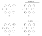
図2を参照すれば、本発明の一実施形態に係る粒子110は、図2の(a)のように、異種の物質からなるコア−シェル(core-shell)112形態で構成されてもよく、図2(b)のように、異種の物質からなるマルチ−コア(multi-core)114形態で構成されてもよく、図2の(c)のように、複数のナノ粒子からなるクラスタ116で構成されてもよく、電荷を有する電荷層118がそれらの粒子を覆う構造で構成されてもよい。
Referring to FIG. 2, the
より具体的に、本発明の一実施形態に係る粒子110は、シリコン(Si)、チタニウム(Ti)、バリウム(Ba)、ストロンチウム(Sr)、鉄(Fe)、ニッケル(Ni)、コバルト(Co)、鉛(Pb)、アルミニウム(Al)、銅(Cu)、銀(Ag)、金(Au)、タングステン(W)、モリブデン(Mo)、亜鉛(Zn)、ジルコニウム(Zr)などの元素やこれらを含む化合物からなり得る。また、本発明の一実施形態に係る粒子110は、PS(polystyrene)、PE(polyethylene)、PP(polypropylene)、PVC(polyvinyl chloride)、PET(polyethylen terephthalate)などの高分子物質からなり得る。また、本発明の一実施形態に係る粒子110は、電荷を有さない粒子或いはクラスタに電荷を有する物質がコーティングされた形態として構成されることもできる。例えば、炭化水素基を有する有機化合物によって表面が加工(或いはコーティング)された粒子、カルボン酸(carboxylic acid)基、エステル(ester)基、アシル(acyl)基を有する有機化合物によって表面が加工(或いはコーティング)された粒子、ハロゲン(F、Cl、Br、Iなど)元素を含む錯化合物によって表面が加工(コーティング)された粒子、アミン(amine)、チオール(thiol)、ホスフィン(phosphine)を含む配位化合物によって表面が加工(コーティング)された粒子、表面にラジカルを形成することで、電荷を有する粒子がこれに該当し得る。このように粒子110の表面をシリカ、高分子、高分子モノマーなどの物質でコーティングすることで、粒子110が溶媒120内で高い分散性と安定性を有するようにできる。
More specifically, the
本発明の一実施形態によれば、溶媒120は、粒子110が溶媒120内に均一に分散され得るように、粒子110と類似の比重を有する物質で構成されてもよく、粒子110が溶媒120内で安定的に分散されるのに適した物質で構成されてもよい。例えば、低誘電率を有するハロゲンカーボンオイル、ジメチルシリコーンオイルなどを含むことができる。
According to an embodiment of the present invention, the solvent 120 may be composed of a material having a specific gravity similar to that of the
また、本発明の一実施形態によれば、粒子110が後述する溶媒120内で沈殿せず、安定したコロイド状態を維持することで、光結晶性を効果的に示すことができるようにするために、粒子110と溶媒120からなるコロイド溶液の界面動電位(electrokinetic potential)(即ち、ゼータ電位)の値が既に設定された値以上で高くなってもよく、粒子110と溶媒120の比重差が既に設定された値以下であってもよく、溶媒120と粒子110の屈折率差が既に設定された値以下であってもよい。例えば、コロイド溶液の界面動電位の絶対値は10mV以上であってもよく、粒子110と溶媒120の比重差は5以下であってもよく、粒子110と溶媒120の屈折率差は0.3以上であってもよい。
In addition, according to an embodiment of the present invention, the
一方、本発明の一実施形態によれば、粒子110は、特定波長の光を反射させることができるように、即ち、固有のカラーを有するように構成され得る。より具体的に、本発明の一実施形態に係る粒子110は、酸化数の調節又は無機顔料、顔料などのコーティングを通じて特定のカラーを有するようになり得る。例えば、本発明に係る粒子110にコーティングされる無機顔料としては、発色団を含むZn、Pb、Ti、Cd、Fe、As、Co、Mg、Alなどが酸化物、硫化物、硫酸塩の形態で使用され得、本発明に係る粒子110にコーティングされる染料としては、蛍光染料、酸性染料、塩基性染料、媒染染料、硫化染料、建染染料(vat dye)、分散染料、反応性染料などが使用され得る。また、本発明の一実施形態によれば、粒子110は、特定のカラーを表示できるように、特定の構造色(structural color)を有する物質であり得る。例えば、シリコン酸化物(SiOx)、チタニウム酸化物(TiOx)などの粒子が屈折率の異なる媒体に一定間隔で均一に配列された形態で構成され、特定波長の光を反射させる物質であり得る。
Meanwhile, according to an embodiment of the present invention, the
また、本発明の一実施形態によれば、溶媒120も特定波長の光を反射させることができるように、即ち、固有のカラーを有するように構成され得る。より具体的に、本発明に係る溶媒120は、顔料、染料を有する物質を含むか、光結晶による構造色を有する物質を含むことができる。 In addition, according to an embodiment of the present invention, the solvent 120 may also be configured to reflect a specific wavelength of light, that is, to have a unique color. More specifically, the solvent 120 according to the present invention may include a substance having a pigment and a dye, or a substance having a structural color due to photocrystal.
<粒子及び溶媒の電気分極特性> <Electrical polarization characteristics of particles and solvent>
また、本発明の一実施形態によれば、表示装置に含まれる粒子が分散された溶媒を含む溶液は、電気分極(electrical polarization)特性−電場印加によって電気分極が変化する−を有することができるが、このような溶液の電気分極特性は、溶液を構成している粒子又は溶媒のうちの少なくとも1つが電気分極特性を示すか、これらの相互作用により電気分極特性が示され得る。また、電気分極特性を示す溶液(粒子及び溶媒)は、原子或いは分子の非対称的な電荷分布などによって外部電場が印加されることによって、電子分極、イオン分極、界面分極及び回転分極のうちの何れか1つによって電気分極される物質を含むことができる。従って、本発明の一実施形態に係る粒子又は溶媒のうちの少なくとも1つは、電場が印加されれば、電気分極が誘発され得、粒子又は溶媒に印加される電場の強度又は方向が変わることによって、粒子又は溶媒のうちの少なくとも1つは、電気分極量が変わり得る。このように電場が変化すれば、電気分極量が変わる特性を可変電気分極特性と言える。電場が印加された時に誘発される電気分極量が大きければ大きいほど、有利であるが、その理由は、これにより粒子間の間隔が更に均一に配列され得るためである。 In addition, according to an embodiment of the present invention, a solution including a solvent in which particles included in a display device are dispersed may have an electrical polarization characteristic—electric polarization changes by application of an electric field. However, the electric polarization characteristics of such a solution may be indicated by at least one of particles or a solvent constituting the solution, or by their interaction. In addition, a solution (particle and solvent) exhibiting electric polarization characteristics can be applied to any one of electronic polarization, ionic polarization, interface polarization, and rotational polarization by applying an external electric field due to an asymmetric charge distribution of atoms or molecules. Or a material that is electrically polarized by one. Therefore, at least one of the particles or the solvent according to an embodiment of the present invention may induce electric polarization when an electric field is applied, and the intensity or direction of the electric field applied to the particle or the solvent changes. Depending on, at least one of the particles or the solvent may change the amount of electric polarization. If the electric field changes in this way, the characteristic that the amount of electric polarization changes can be said to be a variable electric polarization characteristic. The greater the amount of electrical polarization induced when an electric field is applied, the more advantageous, because this allows the spacing between particles to be more evenly arranged.
図3は、本発明の一実施形態によって電場が印加されることによって、粒子又は溶媒が分極される構成を例示的に示す図である。 FIG. 3 is a view exemplarily showing a configuration in which particles or a solvent are polarized by applying an electric field according to an embodiment of the present invention.
図3の(a)及び(b)を参照すれば、外部電場が印加されない場合に、粒子又は溶媒が電気的平衡状態を維持するが、外部電場が印加される場合には、粒子又は溶媒内の電荷が所定方向に移動することによって、分極が誘発され、粒子又は溶媒が分極され得る。図3の(c)及び(d)は、粒子又は溶媒を構成する電気的に非対称的な構成要素によって単位分極(unit polarization)が生成される場合であって、電場を印加しない場合には、前記単位分極が無秩序に配列されて全体の電気分極は現れないか、小さな値を示すが、外部から電場が印加される場合には、単位分極を有する粒子又は溶媒が外部電場の方向によって所定の方向に再配列され得るため、全体として、図3の(a)及び(b)の場合に比べて、相対的に大きい電気分極値(polarization value)を示すことができる。本発明の一実施形態によれば、図3(c)及び(d)に表示された単位分極は、電子又はイオンの非対称的な配置や分子の非対称的な構造で発生でき、このような単位分極によって外部電場が印加されない場合にも、微細な残留分極値(remnant polarization value)が現れ得る。 Referring to (a) and (b) of FIG. 3, when an external electric field is not applied, the particles or solvent maintain an electrical equilibrium state, but when an external electric field is applied, As the charge of the material moves in a predetermined direction, polarization is induced and the particle or solvent can be polarized. 3 (c) and 3 (d) show a case where unit polarization is generated by an electrically asymmetric component constituting a particle or solvent, and when no electric field is applied, The unit polarization is randomly arranged and the entire electric polarization does not appear or shows a small value. However, when an electric field is applied from the outside, the particles or solvent having the unit polarization may have a predetermined value depending on the direction of the external electric field. Since they can be rearranged in the direction, as a whole, a relatively large polarization value can be shown as compared with the cases of FIGS. 3 (a) and 3 (b). According to one embodiment of the present invention, the unit polarization shown in FIGS. 3C and 3D can be generated by an asymmetric arrangement of electrons or ions or an asymmetric structure of molecules, and such units Even when an external electric field is not applied due to polarization, a fine remnant polarization value may appear.
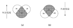
図4は、本発明の一実施形態によって分子の非対称的な配置による単位分極特性を例示的に示す図である。より具体的に、図4は、水分子(H2O)の場合を例示的に示すものであって、水分子以外に、トリクロロエチレン、四塩化炭素、ジイソプロピルエーテル、トルエン、メチル−t−ブチルエーテル、キシレン、ベンゼン、ジエチルエーテル、ジクロロメタン、1,2−ジクロロエタン、酢酸ブチル、イソプロパノール、n−ブタノール、テトラヒドロフラン、n−プロパノール、クロロホルム、酢酸エチル、2−ブタノン、ジオキサン、アセトン、メタノール、エタノール、アセトニトリル、酢酸、ジメチルホルムアミド、ジメチルスルホキシド、炭酸プロピレン、N,N−ジメチルホルムアミド、ジメチルアセトアミド、N−メチルピロリドンなどは、分子構造の非対称性により単位分極特性が示され得るので、本発明に係る粒子又は溶媒を構成する物質として採用され得る。参考までに、物質の分極特性を比較するために用いられる極性指数(polarity index)は、水(H2O)の分極特性に対比して、該当物質の相対的な分極の程度を示す指標であり得る。 FIG. 4 is a diagram illustrating unit polarization characteristics according to an asymmetric arrangement of molecules according to an exemplary embodiment of the present invention. More specifically, FIG. 4 exemplarily shows the case of a water molecule (H 2 O). In addition to the water molecule, trichloroethylene, carbon tetrachloride, diisopropyl ether, toluene, methyl-t-butyl ether, Xylene, benzene, diethyl ether, dichloromethane, 1,2-dichloroethane, butyl acetate, isopropanol, n-butanol, tetrahydrofuran, n-propanol, chloroform, ethyl acetate, 2-butanone, dioxane, acetone, methanol, ethanol, acetonitrile, acetic acid , Dimethylformamide, dimethyl sulfoxide, propylene carbonate, N, N-dimethylformamide, dimethylacetamide, N-methylpyrrolidone and the like can exhibit unit polarization characteristics due to the asymmetry of the molecular structure. It may be employed as the material constituting the medium. For reference, the polarity index used to compare the polarization characteristics of substances is an index that indicates the relative degree of polarization of the substance relative to the polarization characteristics of water (H 2 O). possible.
また、本発明の一実施形態に係る粒子又は溶媒は、外部電場が印加されることによって、分極量が増加し、外部電場が印加されない場合にも、残留分極量が大きく現れ、履歴(hysteresis)が残る強誘電性(ferroelectric)物質を含むことができ、外部電場が印加されることによって、分極量が増加し、外部電場が印加されない場合には、残留分極量が現れず、履歴が残らない超常誘電性(superparaelectric)物質を含むことができる。図5を参照すれば、常誘電性物質510、強誘電性物質520及び超常誘電性物質530の外部電場による履歴曲線を確認できる。
In addition, the particle or solvent according to an embodiment of the present invention increases the polarization amount when an external electric field is applied, and a large amount of residual polarization appears even when an external electric field is not applied. Can be included, and the amount of polarization increases when an external electric field is applied. When no external electric field is applied, no residual polarization appears and no history remains. A superparaelectric material may be included. Referring to FIG. 5, the hysteresis curves of the
また、本発明の一実施形態に係る粒子又は溶媒は、ペロブスカイト(perovskite)構造を有する物質を含むことができるが、ABO3のようなペロブスカイト構造を有する物質として、PbZrO3、PbTiO3、Pb(Zr、Ti)O3、SrTiO3、BaTiO3、(Ba、Sr)TiO3、CaTiO3、LiNbO3などの物質をその例として挙げられる。 In addition, the particles or the solvent according to the embodiment of the present invention may include a substance having a perovskite structure, but as a substance having a perovskite structure such as ABO 3 , PbZrO 3 , PbTiO 3 , Pb ( Examples thereof include Zr, Ti) O 3 , SrTiO 3 , BaTiO 3 , (Ba, Sr) TiO 3 , CaTiO 3 , LiNbO 3 and the like.
図6は、本発明の一実施形態に係る粒子又は溶媒に含まれ得るペロブスカイト構造を有する物質を例示的に示す図である。図6を参照すれば、PbZrO3(又はPbTiO3)に印加される外部電場の方向によってPbZrO3(又はPbTiO3)内でのZr(又はTi)(即ち、ABO3構造でのB)の位置が変動し得、これにより、PbZrO3(又はPbTiO3)全体の極性が変わり得る。 FIG. 6 is a view exemplarily illustrating a substance having a perovskite structure that can be included in a particle or a solvent according to an embodiment of the present invention. Referring to FIG. 6, the position of Zr in PbZrO 3 (or PbTiO 3) PbZrO 3 depending on the direction of the applied external electric field (or PbTiO 3) in (or Ti) (i.e., B in ABO 3 structure) Can vary, which can change the overall polarity of PbZrO 3 (or PbTiO 3 ).
一方、本発明の一実施形態によれば、溶媒は極性指数が1以上である物質を含むことができる。 Meanwhile, according to an embodiment of the present invention, the solvent may include a substance having a polarity index of 1 or more.
また、電気分極の様相を説明すると、第1実施例として電場が印加されなければ、前記溶媒の各分子及び各粒子のうちの少なくとも1つはいかなる電気分極量も有さないが、電場が印加されれば、前記溶媒の各分子及び各粒子のうちの少なくとも1つは電気的に分極され、これにより、前記複数の粒子の電気分極量全体及び前記溶媒の電気分極量全体のうちの少なくとも1つは増加するようになり得る。第2実施例では、電場が印加されなくても、前記溶媒の各分子及び各粒子のうちの少なくとも1つは電気的に分極されているが、前記溶媒の電気分極量全体及び前記複数の粒子の電気分極量全体のうちの少なくとも1つはゼロとなり、電場が印加されれば、前記複数の粒子の電気分極量全体及び前記溶媒の電気分極量全体のうちの少なくとも1つは増加するようになり得る。第3実施例として、電場が印加されなくても、前記溶媒の各分子及び各粒子のうちの少なくとも1つは電気的に分極されており、前記溶媒の電気分極量全体及び前記複数の粒子の電気分極量全体のうちの少なくとも1つはゼロではない第1値を有し、電場が印加されれば、前記複数の粒子の電気分極量全体及び前記溶媒の電気分極量全体のうちの少なくとも1つは前記第1値よりも大きい第2値になり得る。 Also, the aspect of electric polarization will be described. In the first embodiment, when no electric field is applied, at least one of the molecules and particles of the solvent does not have any electric polarization amount, but the electric field is applied. Then, at least one of each molecule and each particle of the solvent is electrically polarized, whereby at least one of the total electric polarization amount of the plurality of particles and the total electric polarization amount of the solvent. One can become increased. In the second embodiment, even if no electric field is applied, at least one of the molecules and particles of the solvent is electrically polarized, but the entire amount of electric polarization of the solvent and the plurality of particles At least one of the total electric polarization amounts of the plurality of particles is zero, and if an electric field is applied, the total electric polarization amount of the plurality of particles and the total electric polarization amount of the solvent are increased. Can be. As a third example, even if no electric field is applied, at least one of the molecules and particles of the solvent is electrically polarized, and the entire amount of electric polarization of the solvent and the plurality of particles At least one of the total electric polarization amounts has a non-zero first value, and when an electric field is applied, at least one of the total electric polarization amount of the plurality of particles and the total electric polarization amount of the solvent. One can be a second value greater than the first value.
<粒子の立体障害効果> <Steric hindrance effect of particles>
また、本発明の一実施形態によれば、表示装置に含まれる粒子相互間に立体障害反発力(steric hindrance repulsion)を発生させるために、粒子表面に立体構造物が形成されるようにすることができる。例えば、官能基(functional group)又は添加剤(surfactant)などが粒子表面に形成される立体構造物として使用され得る。 Also, according to an embodiment of the present invention, a three-dimensional structure is formed on the particle surface in order to generate steric hindrance repulsion between the particles included in the display device. Can do. For example, a functional group or a surfactant can be used as a three-dimensional structure formed on the particle surface.
また、本発明の一実施形態によれば、粒子は電気分極される物質を含み、粒子表面処理を通じて粒子間の立体障害反発力はあるが、帯電された電荷が弱いため、電気泳動効果は最小化するように構成することによって、前記粒子或いは溶液は、外部電場によって電気分極量が変化し、粒子間で局部的引力(short range attraction)が効果的に発生し、粒子表面処理を通じて形成された立体構造物により粒子間で局部的に立体障害反発力(short range steric hindrance repulsion)は効果的に発生するが、外部電場による長距離電気泳動力(long range electophoretic force)により帯電された粒子が電極に偏る現象を最小化できる。即ち、粒子表面に電荷が処理されないため、外部電場によって何れか1つの電極側に電気泳動する現象が最小化され得る。このように立体障害反発力を与えるために、有機リガンド(organic ligand)を粒子表面に処理できる。 Also, according to an embodiment of the present invention, the particles include a substance that is electrically polarized, and there is steric hindrance repulsion between the particles through the particle surface treatment, but since the charged charge is weak, the electrophoretic effect is minimal. The particles or the solution are formed through particle surface treatment, in which the amount of electric polarization is changed by an external electric field, and a short range attraction is effectively generated between the particles. The three-dimensional structure effectively generates a short range steric hindrance repulsion between the particles, but the particles charged by the long range electophoretic force due to the external electric field are the electrodes. Can be minimized. That is, since no charge is processed on the particle surface, the phenomenon of electrophoresis to any one electrode side by an external electric field can be minimized. Thus, in order to give a steric hindrance repulsive force, an organic ligand can be treated on the particle surface.
但し、本発明に係る粒子及び溶媒の構成が必ずしも前記列挙したものに限定されるものではなく、本発明の目的を達成できる範囲内で、即ち、電場によって粒子の間隔が制御され得る範囲内で適切に変更され得ることを明確にしておく。 However, the configuration of the particles and the solvent according to the present invention is not necessarily limited to those listed above, and within a range in which the object of the present invention can be achieved, that is, within a range in which the distance between particles can be controlled by an electric field. Make it clear that it can be changed appropriately.
<表示装置の動作原理及び構成> <Operation principle and configuration of display device>
一方、本発明の一実施形態によれば、同一の符号の電荷を有する複数の粒子が電気分極特性を有する溶媒に分散された状態で粒子及び溶媒に電場が印加される場合、粒子の有する電荷によって複数の粒子には、電場の強度と粒子の電荷量に比例する電気的引力が作用するようになり、これにより複数の粒子は、電気泳動(electrophoresis)されて所定方向に移動しながら、粒子の間隔が狭くなる。一方、これとは反対に、粒子の間隔が狭くなることによって、互いに同一の符号の電荷を有する複数の粒子間で発生する電気的斥力は増加するので、粒子の間隔が継続して狭くはならず、所定のバランスが取れるようになり、これにより複数の粒子は、所定間隔で規則的に配列され得る。また、溶媒の有する電気分極特性によって単位分極された溶媒は、外部から印加される電場と周辺の粒子が有する電荷によって所定の方向に配列され、これにより、粒子を中心として局部的な分極領域が形成され、複数の粒子が所定の間隔を維持した状態で更に規則的、且つ、安定的に配列され得る。即ち、本発明の本実施形態によれば、外部電場による電気的引力、互いに同一の符号の電荷を有する粒子間の電気的斥力及び分極による電気的引力が平衡(equilibrium)をなす距離を置いて複数の粒子が規則的に配列され得る。前記のような原理によって、粒子の間隔が所定間隔で制御され得、所定の間隔を置いて配列された複数の粒子は、光結晶としての機能を行えるようになる。規則的に配列された複数の粒子から反射される光の波長は、粒子の間隔により決定されるため、粒子の間隔を制御することによって、複数の粒子から反射される光の波長を任意に制御できるようになる。ここで、反射される光の波長のパターンは、電場の強度及び方向、粒子の大きさ及び質量、粒子及び溶媒の屈折率、粒子の電荷量、溶媒の電気分極特性、溶媒内の分散された粒子の濃度などの要因によって多様に現れ得る。 On the other hand, according to an embodiment of the present invention, when an electric field is applied to a particle and a solvent in a state where a plurality of particles having the same sign of charge are dispersed in a solvent having electric polarization characteristics, the charge of the particle As a result, an electric attractive force proportional to the strength of the electric field and the amount of electric charge of the particles acts on the plurality of particles. As a result, the plurality of particles are electrophoresed and move in a predetermined direction. The interval of becomes narrower. On the other hand, since the electric repulsive force generated between a plurality of particles having the same charge is increased by decreasing the particle interval, the particle interval is continuously reduced. First, a predetermined balance is achieved, whereby a plurality of particles can be regularly arranged at predetermined intervals. In addition, the unit-polarized solvent by the electric polarization characteristics of the solvent is arranged in a predetermined direction by the electric field applied from the outside and the charge of the surrounding particles, so that a local polarization region centering on the particles is formed. It is formed, and a plurality of particles can be arranged more regularly and stably while maintaining a predetermined interval. That is, according to this embodiment of the present invention, an electrical attractive force due to an external electric field, an electrical repulsive force between particles having the same sign of charge, and an electrical attractive force due to polarization are placed at a distance that equilibrates. A plurality of particles can be regularly arranged. According to the above principle, the interval between the particles can be controlled at a predetermined interval, and a plurality of particles arranged at a predetermined interval can function as a photonic crystal. Since the wavelength of light reflected from a plurality of regularly arranged particles is determined by the interval of the particles, the wavelength of light reflected from the plurality of particles is arbitrarily controlled by controlling the interval of the particles. become able to. Here, the wavelength pattern of the reflected light is the electric field strength and direction, particle size and mass, particle and solvent refractive index, particle charge, solvent electropolarization properties, dispersed in the solvent. It can appear variously depending on factors such as the concentration of particles.
図7は、本発明の一実施形態によって粒子の間隔を制御する構成を概念的に示す図である。図7を参照すれば、外部電場が印加されない場合に、電荷を有する粒子720周辺の単位分極された溶媒710が粒子の電荷と相互作用して粒子方向に強く配列され、粒子からの距離が遠ざかることによって、単位分極された溶媒710が次第に無秩序に配列され得る(図7の(a)参照)。また、図7を参照すれば、外部電場が印加される場合には、粒子720の有する電荷の影響力が及ばない領域(即ち、粒子720から遠く離れた領域)に位置する単位分極された溶媒710が電場の方向に再配列されるのとは異なり、粒子720の有する電荷による電気的引力が強く作用する領域(即ち、粒子720と近接する領域)に位置する単位分極された溶媒710は、粒子720の有する電荷による電気的引力によって単位分極の正極或いは負極が粒子720に向かうようになる方向に配列され得、このように粒子720の周辺領域の単位分極溶媒710が粒子720に向かう方向に配列されている領域、即ち、分極領域730はまるで電気分極された1つの大きな粒子のように作用して周辺の他の分極領域と相互作用を行うことができ、これにより、電荷を有する粒子720が所定の間隔を維持した状態で規則的に配列され得る(図7の(b)参照)。図7は、残留分極を有する溶媒で示したが、残留分極がない状態でも電場が印加されることによって、電気分極が誘発される特性を有する溶媒にも同様に適用され得る。
FIG. 7 is a diagram conceptually showing a configuration for controlling the interval of particles according to an embodiment of the present invention. Referring to FIG. 7, when an external electric field is not applied, the unit-polarized solvent 710 around the charged
次に、本発明の一実施形態によれば、同一の符号の電荷を有し、電気分極特性を有する複数の粒子が溶媒内に分散された状態で粒子及び溶媒に電場が印加される場合、粒子の有する電荷によって複数の粒子には、電場の強度と粒子の電荷量に比例する電気的な力が作用するようになり、これにより複数の粒子は電気泳動されて所定方向に移動しながら、粒子の間隔が狭くなる。一方、これとは反対に、粒子の間隔が狭くなることによって、互いに同一の符号の電荷を有する複数の粒子間で発生する電気的斥力は増加するようになるので、粒子の間隔が継続して狭くはならず、所定のバランスが取れるようになり、これにより複数の粒子は所定の間隔を置いて規則的に配列され得る。また、電気分極特性を示す粒子は、電場により分極が誘発されて電場の方向に分極され、このように分極された複数の粒子間には、電気的引力が局部的に発生するようになり、複数の粒子が所定の間隔を維持した状態で更に規則的、且つ、安定的に配列され得る。即ち、本発明の一実施形態によれば、外部電場による電気的引力、互いに同一の符号の電荷を有する粒子間の電気的斥力及び分極による電気的引力が平衡をなす距離を置いて複数の粒子が規則的に配列され得る。前記のような原理によって、粒子の間隔が所定間隔で制御され得、所定の間隔を置いて配列された複数の粒子は、光結晶としての機能を行えるようになる。規則的に配列された複数の粒子から反射される光の波長は、粒子の間隔により決定されるため、粒子の間隔を制御することによって、複数の粒子から反射される光の波長を任意に制御できるようになる。ここで、反射される光の波長のパターンは、電場の強度及び方向、粒子の大きさ及び質量、粒子及び溶媒の屈折率、粒子の電荷量、粒子の電気分極特性、溶媒内の分散された粒子の濃度などの要因によって多様に現れ得る。 Next, according to an embodiment of the present invention, when an electric field is applied to the particles and the solvent in a state where a plurality of particles having the same sign of charge and having electric polarization characteristics are dispersed in the solvent, Due to the electric charge of the particles, an electric force proportional to the intensity of the electric field and the amount of electric charge of the particles acts on the plurality of particles, thereby causing the plurality of particles to move in a predetermined direction while being electrophoresed. The interval between particles is narrowed. On the other hand, since the electrical repulsive force generated between a plurality of particles having the same sign of charge increases as the particle interval becomes narrower, the particle interval continues. Instead of narrowing, it becomes possible to achieve a predetermined balance, whereby a plurality of particles can be regularly arranged at predetermined intervals. In addition, particles exhibiting electric polarization characteristics are induced by the electric field and polarized in the direction of the electric field, and an electric attractive force is locally generated between the plurality of particles thus polarized, A plurality of particles can be arranged more regularly and stably while maintaining a predetermined interval. That is, according to an embodiment of the present invention, a plurality of particles are placed at a distance that balances the electric attractive force due to an external electric field, the electric repulsive force between particles having the same sign of charge, and the electric attractive force due to polarization. Can be regularly arranged. According to the above principle, the interval between the particles can be controlled at a predetermined interval, and a plurality of particles arranged at a predetermined interval can function as a photonic crystal. Since the wavelength of light reflected from a plurality of regularly arranged particles is determined by the interval of the particles, the wavelength of light reflected from the plurality of particles is arbitrarily controlled by controlling the interval of the particles. become able to. Here, the wavelength pattern of the reflected light is the intensity and direction of the electric field, the size and mass of the particles, the refractive index of the particles and the solvent, the charge amount of the particles, the electric polarization characteristics of the particles, and the dispersion in the solvent. It can appear variously depending on factors such as the concentration of particles.
図8は、本発明の一実施形態によって粒子の間隔を制御する構成を概念的に示す図である。図8を参照すれば、(a)外部電場が印加されない場合には、粒子810が分極されないが、(b)外部電場が印加される場合には、粒子810内に含まれる電気分極特性の物質によって粒子810が分極され得、これにより、粒子810が所定の間隔を維持した状態で規則的に配列され得るようにする。
FIG. 8 is a diagram conceptually showing a configuration for controlling the interval of particles according to an embodiment of the present invention. Referring to FIG. 8, (a) when an external electric field is not applied, the
本発明の前述した実施形態において、溶媒又は粒子の電気分極値が大きいほど、分極領域730又は粒子810間の相互作用の程度を増加させることができ、これにより、粒子が更に規則的に配列されるようにすることができる。
In the above-described embodiments of the present invention, the greater the electrical polarization value of the solvent or particle, the greater the degree of interaction between the
以上の実施形態において、粒子又は溶媒が電気分極特性を有する場合について説明したが、本発明に係る粒子又は溶媒が必ずしも電気分極特性を有すべきではないことを明確にしておく。即ち、粒子又は溶媒が電気分極特性を有さない場合でも、粒子が電荷を有すれば、外部電場による電気的引力及び互いに同一の符号の電荷を有する複数の粒子間の電気的斥力が平衡をなす距離を置いて複数の粒子が規則的に配列され得、このように規則的に配列された複数の粒子は、任意の波長の光を反射させる光結晶を形成できる。 In the above embodiment, the case where the particle or the solvent has the electric polarization characteristic has been described. However, it is clarified that the particle or the solvent according to the present invention should not necessarily have the electric polarization characteristic. That is, even when the particle or solvent does not have an electric polarization characteristic, if the particle has a charge, the electric attractive force due to the external electric field and the electric repulsive force between the particles having the same sign of charge are balanced. A plurality of particles can be regularly arranged at a certain distance, and the plurality of regularly arranged particles can form a photonic crystal that reflects light of an arbitrary wavelength.
また、以上の実施形態において、粒子が電荷を有する場合について説明したが、本発明に係る粒子が必ずしも電荷を有すべきではないことを明確にしておく。即ち、粒子が電荷を有さない場合でも、粒子が電気分極特性を有し、立体障害反発力を発生させることができる立体構造物を有すれば、外部電場により誘発された電気分極により発生する隣接する粒子間の電気的引力及び立体障害効果による斥力が平衡をなす距離を置いて複数の粒子が規則的に配列され得、このように規則的に配列された複数の粒子は、任意の波長の光を反射させる光結晶を形成できる。換言すれば、複数の粒子は、互いに立体障害効果を示せば、電場が印加されることによって、可変電気分極特性により粒子間に作用する静電気的引力と、粒子間に作用する立体障害反発力が相互作用して粒子間の間隔が特定の範囲に到達するようになり、前記粒子間の間隔が前記特定の範囲に到達するようになることによって、複数の粒子から特定波長の光が反射され、特定の色が実現され得るようになる。 Moreover, in the above embodiment, although the case where the particle | grain has an electric charge was demonstrated, it clarifies that the particle | grains concerning this invention should not necessarily have an electric charge. That is, even when the particles have no electric charge, if the particles have a three-dimensional structure that has electric polarization characteristics and can generate steric hindrance repulsive force, the particles are generated by electric polarization induced by an external electric field. A plurality of particles can be regularly arranged at a distance where the repulsive force due to the electric attractive force and the steric hindrance effect between adjacent particles is balanced, and the plurality of regularly arranged particles have an arbitrary wavelength. A photonic crystal that reflects the light can be formed. In other words, if a plurality of particles exhibit a steric hindrance effect with each other, when an electric field is applied, electrostatic attraction acting between the particles due to variable electric polarization characteristics and steric hindrance repulsion acting between the particles. By interacting so that the distance between particles reaches a specific range, and the distance between the particles reaches the specific range, light of a specific wavelength is reflected from a plurality of particles, A specific color can be realized.
<表示装置の動作原理及び構成> <Operation principle and configuration of display device>
図9は、本発明の一実施形態に係る表示装置の構成を例示的に示す図である。 FIG. 9 is a diagram exemplarily showing a configuration of a display device according to an embodiment of the present invention.
図9を参照すれば、本発明の一実施形態に係る表示装置900は、表示部910及び電極920を含むことができる。より具体的に、本発明の一実施形態によれば、表示部910には同一の符号の電荷を有し、電気分極特性を有する複数の粒子912が溶媒914内に分散された状態で含まれ得、本発明の他の実施形態によれば、表示部910には、同一の符号の電荷を有する複数の粒子912が電気分極特性を有する溶媒914内に分散された状態で含まれ得る。一方、本発明のこのような実施形態に係る表示装置の構成を概念的に示せば、それぞれ図10及び図11の通りである。本発明のこのような実施形態については、既に図7及び図8を参照して十分に詳細に説明したので、図10及び図11に関する追加の説明は省略する。説明のために、表示部910と電極902とを区分して表示したが、このような表示装置が特定の対象に内蔵又は包含される場合には、表示部と電極は一体となって表示部として改めて示されることもあり得る。即ち、表示部は、溶液及び電極を何れも含む構成もやはり考慮する必要がある。
Referring to FIG. 9, the
まず、本発明の一実施形態によれば、表示部910は、印加される電場の強度及び方向によって任意の波長の光(即ち、可視光線領域から見ると、フルカラーの光)を反射させる機能を行うが、これは前述した原理により表示部910に印加される電場の強度及び方向によって粒子912の間隔が制御されることによってなされ得る。即ち、前述したように、本発明の一実施形態によれば、単一画素(独立して制御され得る最小の表示単位)内で粒子の間隔が調節され、フルカラーの色が実現され得るため、従来方式と同様に、R、G、Bに対応する3つの画素を用いて、又はR、G、Bに対応する3つのカラーフィルタを用いて色を混色して多様な色を実現しなくて済むので、色の実現が非常に簡単になされ得、これにより、表示装置の構成が非常に簡単になり得る。また、従来方式では、R、G、Bに対応する顔料粒子を用いてこれらを混色して色を実現するため、実現され得る色相にも限界があり、何よりも色の実現方式が複雑になり、駆動回路又は表示装置の構成が複雑になる。しかしながら、本発明では簡単な方式で色を実現でき、駆動回路及び表示装置の構成が複雑にならないので、経済的な側面において大きな価値があり得る。
First, according to an embodiment of the present invention, the
次に、本発明の一実施形態によれば、電極920は、表示部910に対して所定の強度及び方向の電場を印加する機能を行い、電極920を通じて印加される電場の強度及び方向は、表示部910から反射されることを所望する光の波長に合せて適切に制御され得る。
Next, according to an embodiment of the present invention, the
図12〜図14は、本発明の一実施形態によって表示装置に印加される電圧のパターンを例示的に示す図である。 12 to 14 are diagrams exemplarily showing patterns of voltages applied to the display device according to the embodiment of the present invention.
まず、図12を参照すれば、本発明の一実施形態に係る表示装置は、粒子及び溶媒に対して互いに異なる強度及び異なる方向の電場を順次印加して連続的なディスプレイを実現する上で電場の強度及び方向が変わる間に粒子の間隔を初期化する機能を行う制御部(図示せず)を更に含むことができる。より具体的に、本発明の一実施形態に係る制御部は、粒子及び溶媒に電場を印加する電極に第1電圧及び第2電圧を順次印加するにおいて、第1電圧を印加した後、第2電圧を印加する前に粒子及び溶媒に対して第1電圧と反対方向の初期化(reset)電圧を印加することで、第1電圧によって所定の間隔で配列されていた粒子の間隔を初期の状態に戻す機能を行う。これにより、本発明の一実施形態に係る表示装置は、動作速度を向上させ、残像を抑制できるようになるなど、ディスプレイ性能を向上させることができるようになる。また、本発明の一実施形態によれば、初期化電圧は、直前に印加されていた電圧と反対方向に印加されるため、直前に印加されていた電圧によって所定の方向に移動して配列された粒子を強制的に反対方向に移動させて表示装置をオフする場合においても動作速度を速くするという効果を達成できる。 First, referring to FIG. 12, a display device according to an exemplary embodiment of the present invention may apply an electric field of different intensity and direction to particles and a solvent in order to realize a continuous display. A control unit (not shown) may be included to perform a function of initializing the particle interval while the intensity and direction change. More specifically, the controller according to the embodiment of the present invention sequentially applies the first voltage and the second voltage to the electrodes that apply the electric field to the particles and the solvent, and then applies the second voltage after applying the first voltage. By applying a reset voltage in a direction opposite to the first voltage to the particles and the solvent before applying the voltage, the interval between the particles arranged at a predetermined interval by the first voltage is changed to the initial state. Perform the function to return to. As a result, the display device according to the embodiment of the present invention can improve the display performance, such as improving the operation speed and suppressing the afterimage. Also, according to an embodiment of the present invention, the initialization voltage is applied in a direction opposite to the voltage applied immediately before, so that the initialization voltage is moved and arranged in a predetermined direction by the voltage applied immediately before. Even when the particles are forcibly moved in the opposite direction to turn off the display device, the effect of increasing the operation speed can be achieved.
次に、図13を参照すれば、本発明の一実施形態に係る表示装置は、粒子及び溶媒に対して互いに異なる強度及び異なる方向の電場を順次印加して連続的なディスプレイを実現する上で予め粒子の間隔を所定の間隔で維持させる機能を行う制御部(図示せず)を更に含むことができる。より具体的に、本発明の一実施形態に係る制御部は、粒子及び溶媒に電場を印加する電極に第1電圧及び第2電圧を順次印加するにおいて、予め所定の待機(standby)電圧を印加した状態で第1電場と第2電圧を印加することで、粒子の間隔が所望の間隔で迅速に制御され得るようにする機能を行う。これにより、本発明の一実施形態に係る表示装置は、応答速度を高め、画面の切替を速くするなど、ディスプレイ性能を向上させることができるようになる。即ち、従来の電子ペーパー(electronic paper)技術では特定のカラーを表示するために、特定カラーの粒子をセル内の一端から他端を縦断するように移動させなければならなかったが、本発明では可視光線帯域の反射光が現れない程度の相対的に低いレベルの待機電圧を印加して粒子をセル内の一方向に密集させた後、特定レベル以上の電圧を印加して可視光線帯域の光を反射する光結晶を実現できるので、粒子の局部的な位置移動だけでも可視光線帯域の光を反射する光結晶を実現できるようになり、動作速度を速くすることができる。 Next, referring to FIG. 13, a display device according to an embodiment of the present invention sequentially applies electric fields having different intensities and directions to particles and a solvent to realize a continuous display. A control unit (not shown) that performs a function of maintaining the particle interval at a predetermined interval may be further included. More specifically, the controller according to the embodiment of the present invention applies a predetermined standby voltage in advance to sequentially apply the first voltage and the second voltage to the electrodes that apply the electric field to the particles and the solvent. In this state, by applying the first electric field and the second voltage, the function of enabling the particle interval to be quickly controlled at a desired interval is performed. As a result, the display device according to the embodiment of the present invention can improve the display performance, such as increasing the response speed and speeding up the screen switching. That is, in the conventional electronic paper technology, in order to display a specific color, particles of a specific color had to be moved from one end to the other end in the cell. Applying a relatively low level of standby voltage that does not cause visible light in the visible light band to appear and concentrating particles in one direction in the cell, then applying a voltage of a specific level or higher to light in the visible light band Therefore, it is possible to realize a photonic crystal that reflects light in the visible light band only by local movement of the particles, and the operation speed can be increased.
次に、図14を参照すれば、本発明の一実施形態に係る表示装置は、粒子及び溶媒に対して互いに異なる強度及び異なる方向の電場を順次印加して連続的なディスプレイを実現するにおいて、電場の強度及び印加時間などにおいて多様なパターンの電場が印加されるようにする機能を行う制御部(図示せず)を更に含むことができる。より具体的に、本発明の一実施形態に係る制御部は、粒子及び溶媒に電場を印加する電極に電圧を印加するにおいて、所定の電圧で電圧のレベルを上昇又は下降させることができ(図14の(a)参照)、任意に電圧の印加時間又は周期を拡大又は短縮でき(図14の(b)参照)、非連続的なパルス電圧を反復的に印加することで、電圧が連続的に印加された場合と同様の効果を達成できる(図14の(c)参照)。これにより、本発明の一実施形態に係る表示装置は、多様なパターンのディスプレイを可能にし、電力消費を低減するなどディスプレイ性能を向上させることができるようになる。 Next, referring to FIG. 14, the display apparatus according to the embodiment of the present invention sequentially applies different electric fields and different directions to particles and a solvent to realize a continuous display. It may further include a control unit (not shown) that performs a function of applying various patterns of electric fields in terms of electric field strength and application time. More specifically, the control unit according to an embodiment of the present invention can increase or decrease the voltage level at a predetermined voltage when applying a voltage to the electrode that applies an electric field to the particles and the solvent (see FIG. 14 (see (a)), the voltage application time or period can be arbitrarily expanded or shortened (see (b) in FIG. 14), and the voltage is continuously applied by repeatedly applying a non-continuous pulse voltage. The effect similar to that when applied to can be achieved (see FIG. 14C). Accordingly, the display device according to the embodiment of the present invention can display various patterns, and can improve display performance such as reducing power consumption.
但し、本発明に係る電場印加パターンが必ずしも前記列挙したものに限定されるものではなく、本発明の目的を達成できる範囲内で、即ち、電場によって粒子の間隔が制御され得る範囲内で適切に変更され得ることを明確にしておく。 However, the electric field application pattern according to the present invention is not necessarily limited to those listed above, and is appropriately within the range in which the object of the present invention can be achieved, that is, within the range in which the interval of particles can be controlled by the electric field. Make it clear that it can be changed.
図15は、本発明の一実施形態によって太陽電池部を含む表示装置の構成を例示的に示す図である。 FIG. 15 is a view exemplarily showing a configuration of a display device including a solar cell unit according to an embodiment of the present invention.
図15を参照すれば、本発明の一実施形態に係る表示装置1500は、表示装置1500を透過する光を用いて起電力を発生させ、貯蔵する機能を行う太陽電池部1530を更に含むことができる。本発明の一実施形態によれば、太陽電池部1530によって発生した起電力は、電極1520に印加される電圧を発生させるのに使用され得、これにより、表示装置1500は外部からの電源供給に依存しなくても、以上で説明した光結晶性ディスプレイを実現できるようになる。但し、本発明に係る表示装置と太陽電池部との組み合わせが必ずしも前記列挙したものに限定されるものではなく、太陽電池部によって発生した起電力は、表示装置を駆動する以外に他の用途にも使用され得る。
Referring to FIG. 15, the
一方、光結晶性を用いた表示装置は、入射される光のうち、特定波長の光を選択的に反射させる原理によって動作するため、光結晶性を用いた表示装置を利用して完全な黒色又は白色を表現することが容易でないこともあり得る。以下では、光結晶性を用いた表示装置を利用して黒色又は白色をディスプレイする構成について説明する。 On the other hand, a display device using photocrystallinity operates according to the principle of selectively reflecting light of a specific wavelength among incident light, and thus a completely black color is displayed using a display device using photocrystallinity. Or it may not be easy to express white. Below, the structure which displays black or white using the display apparatus using photocrystallinity is demonstrated.
図16は、本発明の一実施形態によって黒色又は白色をディスプレイする表示装置の構成を例示的に示す図である。 FIG. 16 is a diagram illustrating a configuration of a display device that displays black or white according to an embodiment of the present invention.
図16を参照すれば、表示部1610には黒色の粒子1612が含まれ得、電極は透明な上部電極1620及び白色の第1及び第2下部電極1622、1624で構成され得る。まず、表示部1610に印加される電場の強度が既に設定された値未満であるか、電場が印加されない場合には、粒子1612は光結晶をなすことができず、自身の固有なカラーである黒色を反射させるか、粒子と溶媒との屈折率差による散乱光を反射させることができ、これにより表示部1610は、黒色をディスプレイできるようになる(図16の(a)参照)。たとえ、図16には示されていなくても、表示部1610に閾値以上の電場を印加することによって、黒色の粒子1612が上部電極1620側に密着して配列されるようにすることができ、このような場合にも、表示部1610は黒色をディスプレイできるようになる。次に、表示部1610に適切な強度の電場が印加される場合には、光結晶をなす粒子1612から所望の任意の波長範囲の光が反射され得る(図16の(b)参照)。次に、表示部1610に既に設定された強度以上の電場が印加される場合には、電気泳動を起こす電気的引力の大きさが大きくなり過ぎることによって、粒子1612の間隔が適切な間隔で維持できず、粒子1612が一方に偏るおそれがあるが、例えば第1下部電極1622部分にのみ既に設定された値以上の電場が印加されれば、表示部1610に含まれるあらゆる粒子1612は光結晶をなすことができず、第1下部電極1622によってカバーされる狭い領域に偏るようになり得る。従って、第2下部電極1624は、黒色である粒子1612の影響を受けないまま自身の固有なカラーである白色を反射させることができ、これにより、表示部1610は白色をディスプレイできるようになる(図16の(c)参照)。
Referring to FIG. 16, the
但し、図16の実施形態において粒子及び電極のカラーを黒色及び白色に特定したが、必ずしもこれに限定されるものではなく、本発明の表示装置に適用され得る粒子及び電極のカラーはいくらでも変更され得、更には透明に設定されることもあり得る。以下では、光結晶性を用いた表示装置を利用して透明なディスプレイをする構成について説明する。 However, in the embodiment of FIG. 16, the colors of the particles and the electrodes are specified as black and white, but the present invention is not necessarily limited to this, and the colors of the particles and the electrodes that can be applied to the display device of the present invention are changed in any number. In addition, it may be set to be transparent. Below, the structure which makes a transparent display using the display apparatus using photocrystallinity is demonstrated.
図17は、本発明の一実施形態によって透明なディスプレイを実現する表示装置の構成を例示的に示す図である。 FIG. 17 is a diagram exemplarily showing a configuration of a display device that realizes a transparent display according to an embodiment of the present invention.
図17を参照すれば、表示部1710には、SiOxなどの可視光線透過性物質を含む透明な粒子1712が含まれ得、電極はやはり透明な上部電極1720及び下部電極1722で構成され得る。まず、表示部1710に印加される電場の強度が既に設定された値未満であるか、電場が印加されない場合には、粒子1712は光結晶をなすことができず、光結晶によるカラーを示せなくなり、粒子と溶媒間の屈折率差により入射光が散乱され得る(図17の(a)参照)。次に、表示部1710に適切な強度の電場が印加される場合には、光結晶をなす粒子1712から所望の任意の波長範囲の光が反射され得る(図17の(b)参照)。次に、表示部1710に既に設定された強度以上の電場が印加される場合には、電気泳動を起こす電気的引力の大きさが大きくなり過ぎることによって、粒子1712の間隔が可視光線帯域よりも短い波長範囲(例えば、紫外線帯域)の光のみを反射するようになり得る。即ち、このような場合、光結晶によって可視光線帯域の光が反射されずに透過するため、上部電極1720、下部電極1722及び粒子1712が何れも透明になり、これにより、図17の表示装置は、全体的に透明になり得る(図17の(c)参照)。
Referring to FIG. 17, the
一方、図17では具体的に示されていないが、図17の(c)の場合は、光結晶によって可視光線帯域の光が反射されずに透過するため、下部電極として特定のカラーを有する電極が使用されれば、結果として、下部電極のカラーが表示されることもあり得る。 On the other hand, although not specifically shown in FIG. 17, in the case of FIG. 17C, light in the visible light band is transmitted without being reflected by the photonic crystal, and therefore an electrode having a specific color as the lower electrode. As a result, the color of the lower electrode may be displayed.
即ち、本発明に係る表示装置は、特定水準以下の電圧が印加される場合に、入射光が散乱され、半透明或いは不透明になり、特定の範囲の電圧が印加される場合に、粒子の規則的な配列(即ち、光結晶)により可視光線帯域の入射光が反射され、所定のカラーを表示するようになり、特定水準を超える電圧が印加される場合には、粒子の間隔が狭くなり過ぎることによって、可視光線帯域の入射光は透過し、可視光線帯域よりも短い波長範囲である紫外線帯域の入射光が反射されて透明になる。従って、本発明に係る表示装置によれば、任意の波長範囲の光を反射させることができることはもちろん、透明又は不透明にもなり得る色可変ガラスなどを製作でき、更には表示装置の透明度を調節することで、表示装置を基準として一方に存在する特定のカラー又はパターンが反対側に存在する観察者に見えるようにするか、見えなくするディスプレイシステムを実現することもできるようになる。 That is, in the display device according to the present invention, when a voltage below a specific level is applied, incident light is scattered, becomes translucent or opaque, and when a voltage in a specific range is applied, the particle rule The incident light in the visible light band is reflected by a typical arrangement (ie, photonic crystal) and displays a predetermined color, and when a voltage exceeding a specific level is applied, the interval between particles becomes too narrow. Thus, the incident light in the visible light band is transmitted, and the incident light in the ultraviolet band, which is a wavelength range shorter than the visible light band, is reflected and becomes transparent. Therefore, according to the display device of the present invention, it is possible not only to reflect light in an arbitrary wavelength range, but also to produce color variable glass that can be transparent or opaque, and to adjust the transparency of the display device. By doing so, it becomes possible to realize a display system in which a specific color or pattern existing on one side is made visible to an observer existing on the other side with reference to the display device, or is made invisible.
図18は、本発明の一実施形態によって反射型表示装置と発光型表示装置を結合した構成を例示的に示す図である。 FIG. 18 is a view exemplarily showing a configuration in which a reflective display device and a light emitting display device are combined according to an embodiment of the present invention.
また、本発明の一実施形態に係る反射型表示装置1810、1820と別個の発光型表示装置1830、1840を結合できる。より具体的に、本発明の一実施形態に係る反射型表示装置1810、1820の下部に発光型表示装置1830、1840を結合させ、反射型表示装置1810、1820と発光型表示装置1830、1840を互いに独立して駆動させることで、反射型表示装置1810、1820が動作するモードで光結晶による反射光がディスプレイされ、反対に発光型表示装置1830、1840が動作するモードでは所定のバックライト(back light)で発生し、カラーフィルタを透過した光が光結晶粒子を透過してディスプレイされ得る。このように、反射型表示装置と発光型表示装置を結合すれば、発光型表示装置のみを用いる場合と対比して、電力消費を低減でき、反射型表示装置のみを用いる場合と対比して、表示可能なカラーの範囲が広くなるという効果が達成され得る。
In addition, the
<光透過度の制御> <Control of light transmission>
一方、図19及び図20は、本発明の他の実施形態によって光透過度を制御する構成を例示的に示す図である。参考までに、本発明の他の実施形態に係る表示装置1900、2000の上部電極1930、2030及び下部電極1940、1950、2040は、光透過性物質からなり得る。
On the other hand, FIGS. 19 and 20 are diagrams exemplarily showing a configuration for controlling the light transmittance according to another embodiment of the present invention. For reference, the
一方、本発明の他の実施形態によれば、複数の粒子が溶媒内に分散された状態で電極を通じて電場を印加し、電場の強度及び方向のうちの少なくとも1つを調節して粒子の位置又は配列を制御することで、粒子及び溶媒に入射される光の透過度を制御できる。 Meanwhile, according to another embodiment of the present invention, an electric field is applied through an electrode in a state where a plurality of particles are dispersed in a solvent, and at least one of the intensity and direction of the electric field is adjusted to adjust the position of the particles. Alternatively, the transmittance of light incident on the particles and the solvent can be controlled by controlling the arrangement.
まず、本発明の他の実施形態によれば、電場が印加されない場合に溶媒内の粒子が不規則に分散され得、このような場合、粒子及び溶媒に入射される光の透過度は、特に制御されない状態となる。即ち、粒子及び溶媒に入射される光のうちの一部は、不規則に分散されている複数の粒子によって散乱又は反射され、残りの一部は、粒子や溶媒を通り、そのまま透過できるようになる。 First, according to another embodiment of the present invention, particles in the solvent may be irregularly dispersed when an electric field is not applied. In such a case, the transmittance of light incident on the particles and the solvent is particularly It becomes an uncontrolled state. That is, a part of the light incident on the particles and the solvent is scattered or reflected by a plurality of irregularly dispersed particles, and the remaining part can pass through the particles and the solvent and pass through as it is. Become.
次に、本発明の他の実施形態によれば、同一の符号の電荷を有する複数の粒子が溶媒に分散された状態で粒子及び溶媒に電場が印加される場合、粒子の有する電荷によって複数の粒子には、電場の強度と粒子の電荷量に比例する電気的引力が作用するようになり、これにより、複数の粒子は電気泳動され、所定方向に移動するようになる。このとき、印加される電場の強度が既に設定された値以上である場合には、複数の粒子が第1モードと同様、光結晶を形成できず、粒子の間隔が狭くなり、互いに結集した状態で電場を印加する電極側に移動するようになる。 Next, according to another embodiment of the present invention, when an electric field is applied to a particle and a solvent in a state where a plurality of particles having the same sign of charge are dispersed in the solvent, a plurality of particles are charged depending on the charge of the particles An electric attractive force proportional to the intensity of the electric field and the amount of electric charge of the particles acts on the particles, whereby the plurality of particles are electrophoresed and move in a predetermined direction. At this time, when the intensity of the applied electric field is greater than or equal to the preset value, a plurality of particles cannot form a photonic crystal as in the first mode, and the intervals between the particles are narrowed and gathered together. It moves to the electrode side to which the electric field is applied.
図19を参照すれば、電場が印加されない場合には、溶媒内の複数の粒子1910が不規則に配列されるため、入射光が粒子1910によって散乱又は反射され、入射光の光透過度が制御されず、低い状態になるが(図19の(a)参照)、相対的に狭い面積を有する第2下部電極1950に所定の電圧を印加して粒子1910が第2下部電極1950側に集中するようにすれば、相対的に広い面積を有する第1下部電極1940を通じて入射される光は、粒子1910によって散乱又は反射されないので、全体的に見るとき、表示装置1900に入射される光の透過度が高くなり得る(図19の(b)参照)。前記のような原理を用いて第2下部電極1950の面積や第2下部電極1950に印加される電圧の強度を調節することで、表示装置1900に入射される光の光透過度を制御できるようになる。
Referring to FIG. 19, when an electric field is not applied, a plurality of
次に、本発明の他の実施形態によれば、電気分極特性を有する複数の粒子が溶媒内に分散された状態で粒子及び溶媒に電場が印加される場合、複数の粒子は、電場により分極が誘発され、電場の方向によって何れも同一の方向に分極され得るが、同一の方向に分極された複数の粒子間には電気的引力が発生するため、溶媒内に分散されている複数の粒子は互いに引っ張って電場の方向と平行な方向に規則的に配列され得る。従って、電場の強度又は方向を調節して電場の方向と平行な方向に規則的に配列される複数の粒子の配列状態を制御することで、溶媒及び粒子に対する入射光の透過度を制御できるようになる。 Next, according to another embodiment of the present invention, when an electric field is applied to the particles and the solvent in a state where the plurality of particles having electric polarization characteristics are dispersed in the solvent, the plurality of particles are polarized by the electric field. Can be polarized in the same direction depending on the direction of the electric field, but since an electric attractive force is generated between the plurality of particles polarized in the same direction, a plurality of particles dispersed in the solvent Can be regularly arranged in a direction parallel to the direction of the electric field by pulling on each other. Therefore, the transmittance of incident light with respect to the solvent and the particles can be controlled by adjusting the intensity or direction of the electric field to control the arrangement state of the plurality of particles regularly arranged in a direction parallel to the direction of the electric field. become.
図20を参照すれば、電場が印加されない場合には、溶媒内の複数の粒子2010が不規則に配列されるため、入射光2040が粒子2010及び溶媒2020によって散乱又は反射されるか、溶媒2020をそのまま透過するなど入射光2040の光透過度が制御されず、低い状態となる(図20の(a)参照)。更に図20を参照すれば、電気分極特性を有する複数の粒子2010が溶媒2020内に分散された状態で電場が印加される場合には、複数の粒子2010が入射光2040の方向と平行な方向に配列されるため、入射光2040の方向が粒子2010の配列方向となす角度が小さいほど、即ち、入射光2040が入射される方向が粒子2010の配列方向と平行に近いほど、入射光2040が粒子2010によって反射又は散乱される程度が相対的に低くなるため、入射光2040の透過度が相対的に高くなり得る(図20の(b)参照)。しかしながら、反対に、粒子2010の配列方向が入射光2040の方向と平行せず、所定の角をなす場合は、入射光2040が粒子2010によって反射又は散乱される程度が相対的に高くなるため、入射光2040の透過度が相対的に低くなり得る(図20の(c)参照)。
Referring to FIG. 20, when an electric field is not applied, a plurality of
<表示装置の応用> <Application of display device>
一方、本発明の一実施形態によれば、サンプル領域上に表示される少なくとも1つのサンプルカラーのうちの何れか1つがユーザにより選択されることに対応して対象領域上に該当カラーが表示されるようにしたり、多様な検知手段から獲得された検知情報に対応するカラーが対象領域上に表示されるようにすることで、ユーザが対象領域上に表示されるカラーを直観的に制御できるようにするユーザインターフェースを提供し、多様な検知情報を視覚的に表現できる。 On the other hand, according to an embodiment of the present invention, the corresponding color is displayed on the target area in response to the user selecting any one of the at least one sample colors displayed on the sample area. The color displayed on the target area can be controlled intuitively by allowing the user to display the color corresponding to the detection information obtained from various detection means on the target area. A user interface can be provided, and various detection information can be visually expressed.
同様に、本発明の他の実施形態によれば、サンプル領域上に実現される少なくとも1水準のサンプル光透過度のうちの何れか1つがユーザにより選択されることに対応して対象領域上に該当光透過度が実現されるようにしたり、多様な検知手段から獲得された検知情報に対応する光透過度が対象領域上に実現されるようにすることで、ユーザが対象領域上に実現される光透過度を直観的に制御できるようにするユーザインターフェースを提供し、多様な検知情報を視覚的に表現できる。 Similarly, according to another embodiment of the present invention, on the target region in response to any one of the at least one level of sample light transmission realized on the sample region being selected by the user. The user can be realized on the target region by realizing the corresponding light transmittance, or by realizing the light transmittance corresponding to the detection information acquired from various detection means on the target region. It provides a user interface that enables intuitive control of the light transmittance, and can visually express various detection information.
図21は、本発明の一実施形態によって、ユーザにより選択されたサンプルカラーが対象領域に表示され得るようにする表示装置の構成を例示的に示す図である。 FIG. 21 is a diagram exemplarily showing a configuration of a display device that allows a sample color selected by a user to be displayed in a target area according to an embodiment of the present invention.
図21を参照すれば、本発明の一実施形態に係る表示装置2100は、サンプル領域表示部2110、対象領域表示部2120及び制御部2130を含むことができる。
Referring to FIG. 21, the
まず、本発明の一実施形態によれば、サンプル領域表示部2110は、所定のサンプル領域上に少なくとも1つのサンプルカラーを表示したり、少なくとも1水準のサンプル光透過度を実現する機能を行うことで、ユーザがサンプル領域上に表示された少なくとも1つのサンプルカラーのうち、自身が所望のカラーを選択したり、サンプル領域上に実現された少なくとも1水準のサンプル光透過度のうち、自身が所望の光透過度を選択できるようにするユーザインターフェースを提供できる。また、本発明の一実施形態によれば、サンプル領域表示部2110は、ユーザにより選択されたカラー又は光透過度に関する入力信号を生成して後述する制御部2130に伝達する機能を行える。
First, according to an embodiment of the present invention, the sample area display unit 2110 displays at least one sample color on a predetermined sample area, or performs a function of realizing at least one level of sample light transmittance. The user selects a desired color from among at least one sample color displayed on the sample area, or the user desires at least one level of sample light transmittance realized on the sample area. It is possible to provide a user interface that allows the user to select the light transmittance. In addition, according to an embodiment of the present invention, the sample area display unit 2110 can perform a function of generating an input signal related to a color or light transmittance selected by a user and transmitting the input signal to the
より具体的に、本発明の一実施形態に係るサンプル領域表示部2110は、前述したように、複数の粒子及び溶媒に電場を印加し、前記電場の強度及び方向のうちの少なくとも1つを調節して粒子の間隔を制御して粒子から反射される光のカラーが可変的に表示されるようにすることで、サンプル領域上に少なくとも1つのサンプルカラーを表示できる。また、本発明の一実施形態に係るサンプル領域表示部2110は、複数の粒子及び溶媒に電場を印加し、電場の強度及び方向のうちの少なくとも1つを調節して粒子の位置又は配列を制御することで、粒子及び溶媒に入射される光の透過度を制御できる。 More specifically, the sample region display unit 2110 according to an embodiment of the present invention applies an electric field to a plurality of particles and a solvent and adjusts at least one of the intensity and direction of the electric field as described above. Then, by controlling the particle spacing so that the color of the light reflected from the particles is variably displayed, at least one sample color can be displayed on the sample region. The sample region display unit 2110 according to an embodiment of the present invention controls the position or arrangement of particles by applying an electric field to a plurality of particles and a solvent and adjusting at least one of the intensity and direction of the electric field. By doing so, the transmittance of light incident on the particles and the solvent can be controlled.
一方、本発明の一実施形態によれば、サンプル領域上で相互隣接して表示される少なくとも1つのサンプルカラーは、それぞれ互いに連続的な波長範囲を有することができるが、これにより、ユーザが自身の所望するカラーを更に正確に選択するようにできる。また、本発明の一実施形態によれば、サンプルカラーが表示されるサンプル領域上にはタッチパッドが実現され得るが、これにより、ユーザが更に直観的、且つ、自然にサンプルカラーを選択するようにできる。但し、本発明に係るサンプルカラー表示方法やサンプルカラー選択方法が必ずしも前記列挙された実施形態に限定されるものではなく、本発明の目的を達成できる範囲内で変更され得ることを明確にしておく。 On the other hand, according to an embodiment of the present invention, at least one sample color displayed adjacent to each other on the sample region may have a continuous wavelength range from each other. The desired color can be selected more accurately. In addition, according to an embodiment of the present invention, a touch pad may be realized on the sample area where the sample color is displayed, so that the user can select the sample color more intuitively and naturally. Can be. However, it should be clarified that the sample color display method and the sample color selection method according to the present invention are not necessarily limited to the above-described embodiments, and can be changed within a range in which the object of the present invention can be achieved. .
次に、本発明の一実施形態によれば、対象領域表示部2120は、後述する制御部2130から伝達される制御信号を参照して、所定の対象領域上にユーザにより選択されたカラーに対応するカラーを表示したり、ユーザにより選択された光透過度に対応する光透過度を実現する機能を行える。
Next, according to an embodiment of the present invention, the target
より具体的に、本発明の一実施形態に係る対象領域表示部2120は、前述したように、複数の粒子及び溶媒に電場を印加し、前記電場の強度及び方向のうちの少なくとも1つを調節して前記粒子の間隔を制御して前記粒子から反射される光のカラーが可変的に表示されるようにすることで、対象領域上に所定のカラーを表示できる。従って、対象領域上には複数のカラーが混合されて現れるカラーではなく、粒子の間隔によって変わり得る連続的な波長範囲を有する(即ち、アナログ的に変化できる)カラーが表示され得るようになる。但し、本発明に係る対象領域表示部に適用され得るディスプレイ手段が必ずしも前記列挙されたものに限定されるものではなく、本発明の目的を達成できる範囲内で変更され得ることを明確にしておく。例えば、本発明の他の実施形態に係る対象領域表示部には温度によってカラーが変わる染料、圧力によってカラーが変わる染料などが混合されることもあり得る。また、本発明の一実施形態に係る対象領域表示部2120は、複数の粒子及び溶媒に電場を印加し、電場の強度及び方向のうちの少なくとも1つを調節して粒子の位置又は配列を制御することで、粒子及び溶媒に入射される光の透過度を制御できる。
More specifically, as described above, the target
次に、本発明の一実施形態によれば、制御部2130は、サンプル領域上に表示される少なくとも1つのサンプルカラーのうちの何れか1つが選択されることに関する入力信号又は少なくとも1水準のサンプル光透過度のうちの何れか1つが選択されることに関する入力信号をサンプル領域表示部2110から獲得し、このように獲得された入力信号を参照して対象領域に表示されるカラー、即ち、選択されたカラーに対応するカラーを表示することに関する制御信号又は選択された光透過度に対応する光透過度を実現することに関する制御信号を生成でき、このように生成された制御信号は、対象領域表示部2120に伝達され得る。本発明の一実施形態によれば、制御部2130は、オペレーティングシステム、アプリケーションプログラムモジュール及びその他プログラムモジュールの形態で表示装置2100に含まれてもよく、物理的には、多様な公知の記憶装置上に格納されてもよい。また、このようなプログラムモジュールは、表示装置2100と通信可能な遠隔記憶装置に格納されてもよい。一方、このようなプログラムモジュールは、本発明によって後述する特定の業務を行うか、特定の抽象データタイプを実行するルーチン、サブルーチン、プログラム、オブジェクト、コンポーネント、データ構造などを包括するが、これに制限されるものではない。
Next, according to an embodiment of the present invention, the
図22及び図23は、本発明の一実施形態に係る表示装置を含む応用装置の構成を例示的に示す図である。 22 and 23 are diagrams exemplarily showing the configuration of an application device including a display device according to an embodiment of the present invention.
図22を参照すれば、本発明の一実施形態に係る表示装置を用いてノートパソコンの外装のカラーを制御できる。本発明の一実施形態によれば、ノートパソコンの外装の一部に位置するサンプル領域2210上に連続的な波長範囲を有する少なくとも1つのサンプルカラーが表示され得、ユーザがサンプル領域2210上に表示されたサンプルカラーのうち、緑色を選択すれば、これに対応して対象領域2220、即ち、ノートパソコンの外装全体領域上に緑色が表示されるようにできる。一方、本発明の一実施形態によれば、ユーザにより選択される光透過度に対応する光透過度をノートパソコンの対象領域上に実現してノートパソコンの外装の透明度を可変的に制御することもできる。
Referring to FIG. 22, the color of the exterior of the notebook computer can be controlled using the display device according to the embodiment of the present invention. According to an embodiment of the present invention, at least one sample color having a continuous wavelength range may be displayed on a
また、図23を参照すれば、本発明の一実施形態に係る表示装置を用いて家具の外装のカラーを制御できる。本発明の一実施形態によれば、フィルム形態で実現された対象領域2310が家具の外装のうちの少なくとも一部領域をカバーでき、サンプル領域(図示せず)に表示される少なくとも1つのサンプルカラーのうち、ユーザにより選択されるカラーに対応するカラーを対象領域2310上に表示することで、家具のカラーを可変的に制御できるようになる。図23に示すように、家具の主要装飾(例えば、螺鈿細工など)部分のカラーを可変的に表示することで、家具の美感を向上させることができるようになる。一方、本発明の一実施形態によれば、ユーザにより選択される光透過度に対応する光透過度を家具の対象領域上に実現して家具の主要装飾の透明度を可変的に制御することもできる。また、図面には示していないが、家庭で用いられる家庭用冷蔵庫において、そのフレームの表面色をユーザの希望や周辺環境と調和が取れるように変化されるようにできる。
Referring to FIG. 23, the color of the exterior of the furniture can be controlled using the display device according to the embodiment of the present invention. According to one embodiment of the present invention, the
但し、本発明の一実施形態に係る表示装置が適用され得る応用分野が必ずしも前記列挙されたものに限定されるものではなく、壁面、天井、床、外壁、ガラスのような建築資材をはじめとし、かばん、衣服、植木鉢などの多様な分野にいくらでも適用され得ることを明確にしておく。 However, application fields to which the display device according to an embodiment of the present invention can be applied are not necessarily limited to those listed above, and include building materials such as wall surfaces, ceilings, floors, outer walls, and glass. It is clear that it can be applied to various fields such as bags, clothes, flowerpots, etc.
図24は、本発明の一実施形態によって多様な検知手段から獲得された検知情報に対応するカラーを対象領域上に表示され得るようにする表示装置の構成を例示的に示す図である。 FIG. 24 is a diagram exemplarily showing a configuration of a display device that allows a color corresponding to detection information acquired from various detection means according to an embodiment of the present invention to be displayed on a target region.
図24を参照すれば、本発明の一実施形態に係る表示装置2400は、検知部2410、対象領域表示部2420及び制御部2430を含むことができる。
Referring to FIG. 24, a
まず、本発明の一実施形態によれば、検知部2410は、少なくとも1つの検知手段を用いて多様な検知情報を獲得する機能を行える。また、本発明の一実施形態によれば、検知部2410は、検知手段によって獲得された検知情報に関する入力信号を生成して後述する制御部2430に伝達する機能を行える。より具体的に、本発明の一実施形態に係る検知部2410に含まれ得る検知手段には、ジャイロセンサ、温度センサ、湿度センサ、圧力センサ、音響センサ、光センサ、電流センサ、電圧センサ、電荷センサ、酸性度センサ、映像センサ、人体信号センサ、タイマなどがあり、これにより検知の対象となる客体の多様な状態に関する多様な検知情報が獲得され得る。但し、本発明に係る検知部2410に含まれ得る検知手段が必ずしも前記列挙された検知手段に限定されるものではなく、本発明の目的を達成できる範囲内で変更され得ることを明確にしておく。即ち、検知情報は、該当装置の周辺環境に関する情報であるか、該当装置のユーザによって入力又は処理される情報であり得る。
First, according to an embodiment of the present invention, the
次に、本発明の一実施形態によれば、対象領域表示部2420は、後述する制御部2430から伝達される制御信号を参照して、所定の対象領域上に検知部2410から獲得された検知情報に対応するカラーを表示したり、光透過度を実現する機能を行える。より具体的に、本発明の一実施形態に係る対象領域表示部2420は、前述したように、複数の粒子及び溶媒に電場を印加し、前記電場の強度及び方向のうちの少なくとも1つを調節して前記粒子の間隔を制御して前記粒子から反射される光のカラーが可変的に表示されるようにすることで、対象領域上に所定のカラーを表示できる。従って、対象領域上には複数のカラーが混合されて現れるカラーではなく、粒子の間隔によって変わり得る連続的な波長範囲を有する(即ち、アナログ的に変化できる)カラーが表示され得るようになる。但し、本発明に係る対象領域表示部に適用され得るディスプレイ手段が必ずしも前記列挙されたものに限定されるものではなく、本発明の目的を達成できる範囲内で変更され得ることを明確にしておく。例えば、本発明の他の実施形態に係る対象領域表示部には、温度によってカラーが変わる染料、圧力によってカラーが変わる染料などが混合されることもあり得る。また、本発明の一実施形態に係る対象領域表示部2420は、複数の粒子及び溶媒に電場を印加し、電場の強度及び方向のうちの少なくとも1つを調節して粒子の位置又は配列を制御することで、粒子及び溶媒に入射される光の透過度を制御できる。
Next, according to an embodiment of the present invention, the target
次に、本発明の一実施形態によれば、制御部2430は、検知の対象となる客体の状態を検知した結果、得られた検知情報に関する入力信号を検知部2410から獲得し、このように獲得された入力信号を参照して対象領域に表示されるカラー又は対象領域に実現された光透過度に対する制御信号を生成でき、このように生成された制御信号は、対象領域表示部2420に伝達され得る。本発明の一実施形態によれば、制御部2430は、オペレーティングシステム、アプリケーションプログラムモジュール及びその他プログラムモジュールの形態で表示装置2400に含まれてもよく、物理的には、多様な公知の記憶装置上に格納されてもよい。また、このようなプログラムモジュールは、表示装置2400と通信可能な遠隔記憶装置に格納されてもよい。一方、このようなプログラムモジュールは、本発明によって後述する特定の業務を行うか、特定の抽象データタイプを実行するルーチン、サブルーチン、プログラム、オブジェクト、コンポーネント、データ構造などを包括するが、これに制限されるものではない。
Next, according to an embodiment of the present invention, the
例えば、本発明の一実施形態に係る表示装置は、酸性度センサを用いて冷蔵庫内に保管されている食べ物の酸性度を検知し、食べ物の新鮮度、即ち、腐敗の度合いに関する検知情報を獲得でき、このように獲得された検知情報を参照して冷蔵庫の外装の所定の領域に食べ物の新鮮度状態を意味する所定のカラーを表示できるが、より具体的に、食べ物の新鮮度が高い場合には緑色、食べ物の新鮮度が中間である場合には黄色、食べ物の新鮮度が低い場合には赤色を表示できる。また、冷蔵庫の温度を測定して冷蔵庫の温度によってその表面の色が変わる構成も考えられる。 For example, the display device according to an embodiment of the present invention detects the acidity of food stored in a refrigerator using an acidity sensor, and obtains detection information regarding the freshness of the food, that is, the degree of spoilage. It is possible to display the predetermined color that means the freshness state of the food in the predetermined area of the exterior of the refrigerator with reference to the detection information acquired in this way, but more specifically, when the freshness of the food is high Can be displayed in green, yellow when the freshness of the food is intermediate, and red when the freshness of the food is low. Moreover, the structure which measures the temperature of a refrigerator and the surface color changes with the temperature of a refrigerator is also considered.
前述したように、本発明に係る表示装置は、薄い厚さのフレキシブル(flexible)なフィルムの形態で製作され得、フルカラーのディスプレイを実現できるため、電子装置(携帯電話、ノートパソコン、PC、テレビ、個人用マルチメディアプレイヤ(PMP)、冷蔵庫など)、音響装置(スピーカなど)、人体診断装置、時計、電熱装置、冷暖房装置、湿度調節装置、自動車、自転車、家具、衣服、建築資材(室内壁面、建築物外壁、ガラス、広告パネル)のような多様な客体の外装の屈曲がある表面上に容易に適用され得、これにより多様な客体の外装のカラーや透明度を自由に制御できるようになる。 As described above, the display device according to the present invention can be manufactured in the form of a flexible film having a thin thickness, and can realize a full-color display. Therefore, an electronic device (mobile phone, notebook computer, PC, television) , Personal multimedia players (PMP), refrigerators, etc.), acoustic devices (speakers, etc.), human body diagnostic devices, watches, electric heating devices, air conditioning units, humidity control devices, automobiles, bicycles, furniture, clothes, building materials (interior wall surfaces) Can be easily applied on the curved surface of various object exteriors (such as building exterior walls, glass, advertising panels), thereby allowing the color and transparency of various object exteriors to be freely controlled .
図25〜図33は、本発明の一実施形態に係る表示装置を含む応用装置の構成を例示的に示す図である。 25 to 33 are views exemplarily showing the configuration of an application device including a display device according to an embodiment of the present invention.
図25を参照すれば、バッテリの充電状態(即ち、残量)に関する情報を参照して電子装置の外装のカラーを制御できる。より具体的に、本発明の一実施形態によれば、携帯用電子装置の外装のうちの少なくとも一部領域にカラーを可変的に表示できる対象領域2510を配置させ、携帯用電子装置のバッテリの電荷量、電流値、電圧値などを検知した結果、獲得される携帯用電子装置のバッテリの充電状態に関する情報に対応するカラーを対象領域2510に表示することで、携帯用電子装置のバッテリの充電状態を携帯用電子装置の外装のカラーとして視覚的に表現できるようになる。例えば、バッテリの残量が多く残っている場合に、携帯電話の外装2510に特にカラーを表示せず(図25の(a)参照)、バッテリの残量があまり残っていない場合には、携帯電話の外装2510に灰色のカラーを表示してユーザに視覚的に警告できる(図25の(b)参照)。
Referring to FIG. 25, it is possible to control the color of the exterior of the electronic device with reference to information on the state of charge (that is, remaining amount) of the battery. More specifically, according to an embodiment of the present invention, a
また、本発明の一実施形態によれば、電子装置のバッテリの充電状態に関する情報に対応する光透過度を電子装置の外装の対象領域上に実現することで、電子装置のバッテリの充電状態を外装の透明度で視覚的に表現できる。 In addition, according to an embodiment of the present invention, the state of charge of the battery of the electronic device is achieved by realizing light transmittance corresponding to the information regarding the state of charge of the battery of the electronic device on the target area of the exterior of the electronic device. It can be expressed visually by the transparency of the exterior.
図26を参照すれば、ユーザに提供されているコンテンツに関する情報を参照してノートパソコン、PCなどの端末装置の外装カラーを制御できる。より具体的に、本発明の一実施形態によれば、端末装置のモニタの外装のうちの少なくとも一部領域(例えば、モニタのベゼル領域)にカラーを可変的に表示できる対象領域2610を配置させ、モニタ上に表示されているウェブサイトが有害なウェブサイトか否かに関する文脈情報を認識した結果、獲得されるコンテンツが有害か否かに関する情報に対応するカラーを対象領域2610に表示することで、端末装置上で提供されるコンテンツの有害性を端末装置のモニタの外装のカラーとして視覚的に表現できるようになる。例えば、端末装置のモニタを通じて健全なコンテンツが提供されている場合に、モニタのベゼル2610に特にカラーを表示せず(図26の(a)参照)、有害なコンテンツが提供されている場合には、モニタのベゼル2610に赤色のカラーを表示できる(図26の(b)参照)。前記実施形態と同様の原理を用いて、コンテンツの種類、内容、受信される通話の発信者などによって端末装置の外装のカラーを可変的に表示することもできる。
Referring to FIG. 26, it is possible to control the exterior color of a terminal device such as a notebook personal computer or a PC with reference to information relating to content provided to the user. More specifically, according to an embodiment of the present invention, a
また、本発明の一実施形態によれば、端末装置で提供されているコンテンツに関する情報に対応する光透過度を端末装置の外装の対象領域上に実現することで、端末装置で提供されているコンテンツに関する情報を外装の透明度で視覚的に表現できる。 Moreover, according to one Embodiment of this invention, it implement | achieves in the terminal device by implement | achieving the light transmittance corresponding to the information regarding the content provided with the terminal device on the object area | region of the exterior of a terminal device. Information about contents can be visually expressed by the transparency of the exterior.
図27を参照すれば、周辺環境に関する情報を参照して、ヘルメット、ジャケット、天幕などの偽装用装置の外装のカラーを制御できる。より具体的に、本発明の一実施形態によれば、偽装用ヘルメットの外装のうちの少なくとも一部領域にカラーを可変的に表示できる対象領域2710を配置させ、偽装用ヘルメットの周辺環境の映像のカラー、パターン、明るさなどを認識した結果、獲得される周辺環境に関する情報に対応するカラーを対象領域2710に表示することで、偽装用ヘルメットのカラー、パターン、明るさなどが周辺環境のそれと類似するように、偽装用ヘルメットの外装のカラーを調節できるようになる。例えば、偽装用ヘルメットの周辺にコンクリート壁がある場合に、偽装用ヘルメットの外装2710にコンクリート壁と類似のカラー及びパターンを表示でき(図27の(a)参照)、偽装用ヘルメットの周辺に木の葉が多い場合には、偽装用ヘルメットの外装2710に木の葉と類似のカラー及びパターンを表示できる(図27の(b)参照)。前記実施形態と同様の原理を用いて、偽装用ジャケット、偽装用天幕などの外装のカラーを調節することもできる。
Referring to FIG. 27, it is possible to control the exterior color of a camouflage device such as a helmet, jacket, and awning by referring to information about the surrounding environment. More specifically, according to an embodiment of the present invention, a
また、本発明の一実施形態によれば、周辺環境に関する情報に対応する光透過度を対象領域に実現することで、偽装用ヘルメットの透明度が周辺環境のそれと類似するように、偽装用ヘルメットの外装の光透過度を調節できるようになる。 In addition, according to an embodiment of the present invention, by realizing the light transmittance corresponding to the information about the surrounding environment in the target area, the transparency of the camouflaging helmet is similar to that of the surrounding environment. The light transmittance of the exterior can be adjusted.
図28を参照すれば、出力される音響に関する情報を参照して音響装置の外装のカラーを制御できる。より具体的に、本発明の一実施形態によれば、音響装置の外装のうちの少なくとも一部領域にカラーを可変的に表示できる対象領域2810を配置させ、出力される音響の強度、周波数、リズム、音程、拍子、ジャンルなどを認識した結果、得られる音響に関する情報に対応するカラーを対象領域2810に表示することで、音響装置から出力される音響に関する情報を音響装置の外装のカラーとして視覚的に表現できるようになる。例えば、音響装置から出力される音響のジャンルがクラシックの場合とダンスの場合に、音響装置の外装2810に互いに異なるカラー及びパターンを表示できる(図28の(a)及び(b)参照)。
Referring to FIG. 28, it is possible to control the color of the exterior of the audio device by referring to the information relating to the output sound. More specifically, according to an embodiment of the present invention, the
また、本発明の一実施形態によれば、音響に関する情報に対応する光透過度を対象領域に実現することで、音響装置から出力される音響に関する情報を音響装置の外装の透明度で視覚的に表現できるようになる。 In addition, according to an embodiment of the present invention, by realizing light transmittance corresponding to information related to sound in the target region, information related to sound output from the sound device is visually expressed by transparency of the exterior of the sound device. It becomes possible to express.
図29を参照すれば、人体の状態に関する情報を参照して運動装置や人体診断装置の外装のカラーを制御できる。より具体的に、本発明の一実施形態によれば、運動装置や人体診断装置の外装のうちの少なくとも一部領域にカラーを可変的に表示できる対象領域2910を配置させ、運動装置や人体診断装置を用いるユーザの心拍数、血圧、体温、脳波などを検知した結果、得られる人体の状態に関する情報に対応するカラーを対象領域2910に表示することで、人体の状態に関する情報を運動装置や人体診断装置の外装のカラーとして視覚的に表現できるようになる。例えば、ランニングマシンを利用するユーザの心拍数が60回に過ぎない場合に、ランニングマシンの外装2910に特にカラーを表示せず(図29の(a)参照)、ユーザの心拍数が120回に該当する場合には、ランニングマシンの外装2910に赤色のカラーを表示できる(図29の(b)参照)。
Referring to FIG. 29, it is possible to control the color of the exterior of the exercise device or the human body diagnosis device with reference to information on the state of the human body. More specifically, according to one embodiment of the present invention, the
また、本発明の一実施形態によれば、人体の状態に関する情報に対応する光透過度を対象領域に実現することで、人体の状態に関する情報を運動装置や人体診断装置の外装の透明度で視覚的に表現できるようになる。 In addition, according to an embodiment of the present invention, by realizing light transmittance corresponding to information on the state of the human body in the target region, information on the state of the human body can be visualized with transparency of the exterior of the exercise device or the human body diagnosis device. Will be able to express.
図30を参照すれば、時間又は時刻に関する情報を参照して時計やタイマの外装のカラーを制御できる。より具体的に、本発明の一実施形態によれば、時計やタイマの外装のうちの少なくとも一部領域にカラーを可変的に表示できる対象領域3010を配置させ、時間に関する情報に対応するカラーを対象領域3010に表示することで、時間に関する情報を時計やタイマの外装のカラーとして視覚的に表現できるようになる。例えば、午前時間帯、午後時間帯及び夕方時間帯にそれぞれ時計の外装3010のカラーを異なるように表示できる(図30の(a)、(b)及び(c)参照)。
Referring to FIG. 30, it is possible to control the color of the exterior of the clock or timer with reference to information on time or time. More specifically, according to an embodiment of the present invention, a
また、本発明の一実施形態によれば、時間に関する情報に対応する光透過度を対象領域に実現することで、時間に関する情報を時計やタイマの外装の透明度で視覚的に表現できるようになる。 In addition, according to an embodiment of the present invention, by realizing the light transmittance corresponding to the information related to time in the target area, the information related to time can be visually expressed by the transparency of the exterior of the clock or timer. .
図31を参照すれば、温度に関する情報を参照して電熱装置や冷暖房装置の外装のカラーを制御できる。より具体的に、本発明の一実施形態によれば、電熱装置や冷暖房装置の外装のうちの少なくとも一部領域にカラーを可変的に表示できる対象領域3110を配置させ、検知される温度に関する情報に対応するカラーを対象領域3110に表示することで、温度に関する情報を電熱装置や冷暖房装置の外装のカラーとして視覚的に表現できるようになる。例えば、アイロンのプレートの温度が摂氏20℃に過ぎない場合に、アイロンの取っ手部分3110に特にカラーを表示せず(図31の(a)参照)、アイロンのプレートの温度が摂氏100℃で非常に熱い場合には、アイロンの取っ手部分3110に赤色のカラーを表示してユーザに視覚的に警告できる(図31の(b)参照)。
If FIG. 31 is referred, the color of the exterior of an electric heating apparatus or an air conditioning apparatus can be controlled with reference to the information regarding temperature. More specifically, according to one embodiment of the present invention, information on the detected temperature is provided by arranging a
また、本発明の一実施形態によれば、検知される温度に関する情報に対応する光透過度を対象領域に表示することで、温度に関する情報を電熱装置や冷暖房装置の外装の透明度で視覚的に表現できるようになる。 In addition, according to an embodiment of the present invention, the light transmission corresponding to the detected temperature information is displayed in the target area, so that the temperature information is visually indicated by the transparency of the exterior of the electric heating device or the air conditioning device. It becomes possible to express.
図32を参照すれば、湿度に関する情報を参照して湿度調節装置の外装のカラーを制御できる。本発明の一実施形態によれば、湿度調節装置の外装のうちの少なくとも一部領域にカラーを可変的に表示できる対象領域3210を配置させ、検知される湿度に関する情報に対応するカラーを対象領域3210に表示することで、湿度に関する情報を湿度調節装置の外装のカラーとして視覚的に表現できるようになる。例えば、加湿器によって測定された相対湿度が20%に過ぎない場合に、加湿器の外装3210に特にカラーを表示せず(図32の(a)参照)、相対湿度が80%に該当する場合には、加湿器の外装3210に青色のカラーを表示できる(図32の(b)参照)。前記実施形態と同様の原理を用いて、植木鉢に含まれている水分の湿度によって植木鉢の外装のカラーを可変的に表示することもできる。
Referring to FIG. 32, the color of the exterior of the humidity control apparatus can be controlled with reference to information on humidity. According to an embodiment of the present invention, a
また、本発明の一実施形態によれば、検知される湿度に関する情報に対応する光透過度を対象領域に表示することで、湿度に関する情報を湿度調節装置の外装の透明度で視覚的に表現できるようになる。 In addition, according to an embodiment of the present invention, the information on humidity can be visually expressed by the transparency of the exterior of the humidity control device by displaying the light transmittance corresponding to the information on the detected humidity in the target area. It becomes like this.
図33を参照すれば、運動状態に関する情報を参照して自動車、オートバイ、自転車、ボード、駒などの動く装置の外装のカラーを制御できる。本発明の一実施形態によれば、自動車などの動く装置の外装のうちの少なくとも一部領域にカラーを可変的に表示できる対象領域3310を配置させ、自動車などの動く装置の速度、加速度、角速度、角加速度などを検知した結果、獲得される運動状態に関する情報に対応するカラーを対象領域3310に表示することで、運動状態に関する情報を自動車などの動く装置の外装のカラーとして視覚的に表現できるようになる。例えば、自動車の速度が30km/hに過ぎない場合には、自動車のダッシュボード3310に特にカラーを表示せず(図33の(a)参照)、自動車の速度が100km/hで速い場合には、自動車のダッシュボード3310に赤色のカラーを表示してユーザに視覚的に警告できる(図33の(b)参照)。
Referring to FIG. 33, it is possible to control the exterior color of a moving device such as an automobile, a motorcycle, a bicycle, a board, or a piece by referring to information on the motion state. According to an embodiment of the present invention, a
また、本発明の一実施形態によれば、運動状態に関する情報に対応する光透過度を対象領域に表示することで、運動状態に関する情報を自動車などの動く装置の外装の透明度として視覚的に表現できるようになる。 In addition, according to an embodiment of the present invention, the information on the motion state is visually expressed as the transparency of the exterior of the moving device such as an automobile by displaying the light transmittance corresponding to the information on the motion state in the target area. become able to.
即ち、本発明の一側面に係る方法は、少なくとも1つの検知手段によって検知される情報を獲得する情報獲得段階(例えば、電熱装置の温度を獲得する段階)と、前記情報に基づいて電圧信号を生成する電圧信号生成段階(前記温度に基づいて対応する電圧信号を生成する段階)と、前記生成された電圧信号に基づいて対象の表示領域のカラー及び透過度のうちの少なくとも1つを可変的に調節する表示段階(電熱装置のフレームの色を調節する段階)とを含み、前記表示領域で表示されるカラーに対応する波長は、単一画素内で連続的に又はアナログ方式で変わり得るため、既存のR、G、Bをデジタル方式で混合する方式に比べて、前述したような多様な長所を有するようになる。 That is, a method according to an aspect of the present invention includes an information acquisition step (for example, acquiring a temperature of an electric heating device) for acquiring information detected by at least one detection unit, and a voltage signal based on the information. A voltage signal generation step to generate (a step of generating a corresponding voltage signal based on the temperature), and at least one of a color and a transparency of a target display area based on the generated voltage signal is variable. The wavelength corresponding to the color displayed in the display area may vary continuously or in an analog manner within a single pixel. Compared to the conventional method of mixing R, G, and B in a digital manner, it has various advantages as described above.
<表示部の実験結果> <Experimental result of display part>
まず、図34及び図35は、本発明の一実施形態によって電荷を有する粒子を電気分極特性を有する溶媒に分散させた状態で電場を印加する実験を行った結果、粒子から反射される光をそれぞれグラフ及び写真として示す図である。参考までに、図34及び図35の実験において、負電荷に帯電され、シリコン酸化膜がコーティングされた100nm〜200nmサイズの粒子が電荷を有する粒子として用いられ、極性指数が1より大きい溶媒が電気分極特性を有する溶媒として用いられ、粒子及び溶媒に対して電場を印加するために印加された電圧の強度は0V〜5Vの範囲内で多様に設定された。一方、図34に示すグラフは、多様な強度の電場が印加される場合に、粒子から反射される光の反射度を可視光線帯域の波長範囲で示すものであって、図34において電場の強度の変化による反射光の波長パターンの変化の程度が大きくなるほど、粒子の間隔が大きく変化することを意味し、これは他ならぬ電場の強度を制御することで、粒子から更に多様な波長の光を反射させることができることを意味する。 First, FIG. 34 and FIG. 35 show the light reflected from a particle as a result of an experiment in which an electric field is applied in a state in which charged particles are dispersed in a solvent having electric polarization characteristics according to an embodiment of the present invention. It is a figure shown as a graph and a photograph, respectively. For reference, in the experiments of FIGS. 34 and 35, particles having a size of 100 nm to 200 nm charged with a negative charge and coated with a silicon oxide film are used as charged particles. Used as a solvent having polarization characteristics, the intensity of the voltage applied to apply an electric field to the particles and the solvent was variously set within a range of 0V to 5V. On the other hand, the graph shown in FIG. 34 shows the reflectivity of the light reflected from the particles in the wavelength range of the visible light band when an electric field having various intensities is applied. The greater the degree of change in the wavelength pattern of the reflected light due to the change in light, the greater the change in the spacing of the particles. This means that by controlling the intensity of the electric field, the light of various wavelengths from the particles. Can be reflected.
図34を参照すれば、印加される電場の強度(即ち、電圧の強度)によって粒子から反射される光の波長パターンが多様に変化することが確認でき、より具体的には、印加される電場の強度(即ち、電圧の強度)が増加するほど、粒子から反射される光の波長が全般的に短くなることが確認できる。図34の実験結果によれば、印加される電場を強度(即ち、電圧の強度)が増加するほど、粒子から反射される光のカラーが赤色系列から青色系列に変化することが分かるが、図35を参照すれば、前記のような反射光のカラーの変化を視覚的に確認できる。 Referring to FIG. 34, it can be confirmed that the wavelength pattern of the light reflected from the particles varies depending on the intensity of the applied electric field (that is, the voltage intensity), and more specifically, the applied electric field. It can be confirmed that the wavelength of the light reflected from the particles is generally shortened as the intensity of the light (that is, the voltage intensity) increases. According to the experimental results of FIG. 34, it can be seen that the color of the light reflected from the particles changes from the red series to the blue series as the intensity of the applied electric field (that is, the voltage intensity) increases. 35, it is possible to visually confirm the change in the color of the reflected light as described above.
次に、図36及び図37は、本発明の一実施形態によって電荷を有する粒子を互いに異なる極性指数を有する多様な溶媒に分散させた状態で電場を印加する実験を行った結果、粒子から反射される光の波長をグラフとして示す図である。参考までに、図36及び図37の実験において、負電荷に帯電され、シリコン酸化膜がコーティングされた100nm〜200nmサイズの粒子が電荷を有する粒子として用いられ、極性指数がそれぞれ0、2、4及び5である溶媒が電気分極特性を有する溶媒として用いられた。より具体的に、図36のグラフ(a)、(b)、(c)及び(d)は、極性指数がそれぞれ0、2、4及び5である溶媒に対して行った実験結果を示し、図37のグラフ(a)、(b)、(c)及び(d)は、極性指数が0である溶媒と極性指数が4である溶媒をそれぞれ90:10、75:25、50:50及び0:100の割合で混合した溶媒に対して行った実験結果を示す。一方、図36及び図37に示すグラフは、多様な強度の電場が印加される場合に、粒子から反射される光の反射度を可視光線帯域の波長範囲で示すものであって、電場の強度の変化による反射光の波長パターンの変化の程度が大きくなるほど、粒子の間隔が大きく変化することを意味し、これは他ならぬ電場の強度を制御することで、粒子から更に多様な波長の光を反射させることができることを意味する。 Next, FIG. 36 and FIG. 37 show a result of an experiment in which an electric field is applied in a state where charged particles are dispersed in various solvents having different polarity indexes according to an embodiment of the present invention. It is a figure which shows the wavelength of the light to be performed as a graph. For reference, in the experiments of FIGS. 36 and 37, particles having a size of 100 nm to 200 nm charged with a negative charge and coated with a silicon oxide film are used as charged particles, and the polarity index is 0, 2, 4 respectively. And 5 were used as solvents with electropolarization properties. More specifically, graphs (a), (b), (c), and (d) of FIG. 36 show the results of experiments performed on solvents having a polarity index of 0, 2, 4, and 5, respectively. Graphs (a), (b), (c), and (d) in FIG. 37 show a solvent with a polarity index of 0 and a solvent with a polarity index of 4, respectively 90:10, 75:25, 50:50, and The experimental result performed with respect to the solvent mixed in the ratio of 0: 100 is shown. On the other hand, the graphs shown in FIGS. 36 and 37 show the reflectivity of the light reflected from the particles in the wavelength range of the visible light band when an electric field having various intensities is applied. The greater the degree of change in the wavelength pattern of the reflected light due to the change in light, the greater the change in the spacing of the particles. This means that by controlling the intensity of the electric field, the light of various wavelengths from the particles. Can be reflected.
図36を参照すれば、極性指数が0である溶媒に対する実験結果を示すグラフ(a)では、電場の強度(即ち、電圧の強度)が変化しても、反射光の波長パターンが殆ど変わらないことが確認でき、極性指数が高くなるほど(即ち、グラフ(a)から(d)へ行くほど)、電場の強度(即ち、電圧の強度)による反射光の波長パターンの変化が大きく示されることが確認できる。また、図37を参照すれば、極性指数が高い溶媒の比率が増加するほど(即ち、グラフ(a)から(d)へ行くほど)、電場の強度(即ち、電圧の強度)による反射光の波長パターンの変化が大きく示されることが確認できる。 Referring to FIG. 36, in the graph (a) showing the experimental results for a solvent having a polarity index of 0, the wavelength pattern of reflected light hardly changes even when the electric field strength (that is, voltage strength) changes. It can be confirmed that the change in the wavelength pattern of the reflected light due to the intensity of the electric field (that is, the intensity of the voltage) becomes larger as the polarity index becomes higher (that is, from the graphs (a) to (d)). I can confirm. Referring to FIG. 37, as the ratio of the solvent having a high polarity index increases (that is, from the graph (a) to (d)), the reflected light due to the electric field strength (that is, voltage strength) increases. It can be confirmed that the change in the wavelength pattern is greatly shown.
以上で説明した実験結果に照らしてみるとき、本発明の一実施形態に係る表示装置によれば、粒子の電荷量又は分極量、溶媒の分極量又は印加される電場の強度を適切に調節することで、任意の波長の光を反射できる光結晶を実現できるようになり、これにより任意の波長範囲の(full spectrum)ディスプレイを実現できるようになることが確認できる。 In light of the experimental results described above, according to the display device according to an embodiment of the present invention, the charge amount or polarization amount of the particles, the polarization amount of the solvent, or the strength of the applied electric field is appropriately adjusted. Thus, it becomes possible to realize a photonic crystal that can reflect light of an arbitrary wavelength, and thereby, it can be confirmed that a full spectrum display of an arbitrary wavelength range can be realized.
次に、図38及び図39は、本発明の一実施形態によって電荷を有し、電気分極特性を有する粒子を溶媒に分散させた状態で電場を印加する実験を行った結果、粒子から反射される光をグラフ及び写真として示す図である。参考までに、図38及び図39の実験において、それぞれ電荷を有するように帯電されたSrTiO3粒子(図38の(a)参照)及びBaTiO3粒子(図38の(a)参照)が電荷を有し、電気分極特性を有する粒子として用いられ、前記粒子を極性指数が0である溶媒に分散させた。 Next, FIG. 38 and FIG. 39 are reflected from particles as a result of an experiment in which an electric field is applied in a state where particles having electric charge and electric polarization characteristics are dispersed in a solvent according to an embodiment of the present invention. FIG. For reference, in the experiments of FIG. 38 and FIG. 39, SrTiO 3 particles (see FIG. 38 (a)) and BaTiO 3 particles (see FIG. 38 (a)) charged so as to have charges are charged. The particles were used as particles having electric polarization characteristics, and the particles were dispersed in a solvent having a polarity index of 0.
図38を参照すれば、粒子及び溶媒に印加される電場の強度が大きくなるほど、光の反射度が全般的に低くなることが確認できる。このような実験結果は、電場が印加されることによって、溶媒内に分散された粒子が電気分極され、電場方向に配列され得(図39の(b)参照)、このような配列によって入射光を反射させることができる粒子の数が少なくなるようになり、光の反射度が減少するものと解釈され得る。たとえ、本実験では電気分極特性を有する粒子を無極性溶媒に分散させた状態で電場を印加する構成を用いて反射光の波長を急激に変化させることはできなくても、電場が印加されることによって、粒子が一定の方向に配列されることを確認し、これから粒子表面の電荷などの条件を最適化することで、反射光の波長も変化させることができると見られる。 Referring to FIG. 38, it can be confirmed that the greater the intensity of the electric field applied to the particles and the solvent, the lower the light reflectivity. As a result of such an experiment, when an electric field is applied, particles dispersed in the solvent can be electrically polarized and arranged in the direction of the electric field (see FIG. 39B). It can be interpreted that the number of particles that can be reflected becomes smaller and the light reflectivity decreases. For example, in this experiment, an electric field is applied even if the wavelength of the reflected light cannot be changed rapidly using a configuration in which the electric field is applied in a state where particles having electric polarization characteristics are dispersed in a nonpolar solvent. Thus, it is confirmed that the wavelength of the reflected light can be changed by confirming that the particles are arranged in a certain direction and optimizing conditions such as the charge on the particle surface.
次に、図40は、本発明の一実施形態によって透明なディスプレイを実現する構成に対する実験結果を示す図である。参考までに、本実験では、可視光線帯域の光を透過させる透明な材質からなる粒子、溶媒及び電極を用い、光結晶性を用いた表示装置に印加される電場の強度を次第に増加させながら、ディスプレイの透明な程度を視覚的に観察した。
図40を参照すれば、電場の強度が相対的に小さい場合に、光結晶によって可視光線帯域の光が反射されることで、表示装置上に所定のカラーがディスプレイされていることが確認できる(図40の(a)及び(b)参照)。しかしながら、電場の強度が相対的に大きい場合には、光結晶によって反射される光の波長範囲が可視光線帯域から紫外線帯域へ順次シフトされることによって、表示装置上にディスプレイされるカラーが顕著が薄くなったことが確認でき(図40の(c)参照)、電場の強度が更に大きくなった場合には、光結晶によって反射される光の波長範囲が可視光線帯域を完全に逸脱することによって、表示装置は何らのカラーもディスプレイしないまま透明な状態になることが確認できる(図40の(d)及び(e)参照)。このような特性を利用すれば、本発明に係る表示装置を色可変ガラスなどのスマートガラス(smart glass)として活用することもできる。
Next, FIG. 40 is a diagram showing experimental results for a configuration that realizes a transparent display according to an embodiment of the present invention. For reference, in this experiment, particles, a solvent and an electrode made of a transparent material that transmits light in the visible light band are used, and while gradually increasing the intensity of the electric field applied to the display device using photocrystallinity, The degree of transparency of the display was visually observed.
Referring to FIG. 40, when the intensity of the electric field is relatively small, light in the visible light band is reflected by the photonic crystal, so that it can be confirmed that a predetermined color is displayed on the display device ( 40 (a) and (b)). However, when the intensity of the electric field is relatively large, the wavelength range of light reflected by the photonic crystal is sequentially shifted from the visible light band to the ultraviolet light band, so that the color displayed on the display device is noticeable. It can be confirmed that the thickness has decreased (see FIG. 40 (c)), and when the electric field intensity is further increased, the wavelength range of the light reflected by the photonic crystal completely deviates from the visible light band. It can be confirmed that the display device is in a transparent state without displaying any color (see FIGS. 40D and 40E). If such characteristics are utilized, the display device according to the present invention can be utilized as smart glass such as color variable glass.
一方、図41は、本発明の一実施形態に係る表示装置の視野角によるディスプレイ性能を実験した結果(即ち、ディスプレイの視野角に関する実験結果)を示す図である。
図41を参照すれば、本発明の一実施形態に係る表示装置に対する視野角が20゜から70゜まで変化しても、反射される光のカラーパターン4110〜4160に殆ど変化がないことが確認できる。従来の光結晶性表示装置は、視野角によってカラーパターンの変化が大きく示されるという短所があるが、本発明に係る表示装置は、視野角によるカラーパターンの変化が殆どなく、一定に示されるという長所を有していることが分かる。このような長所は、本発明に係る表示装置により形成される光結晶が短距離秩序(short range order)を有する擬似光結晶(準結晶、quasi crystal)であるという点に起因するものと解釈され得るが、これにより、本発明に係る表示装置は、長距離秩序(long range order)を有する光結晶を形成するだけである従来の表示装置に対比するとき、ディスプレイの性能が遥かに向上され得るようになる。図示のように、一実施形態によれば、視野角が20゜から70゜まで変化しても、CIE xy色度座標でx値及びy値は5%以内で変化するようになる。また。本発明の一実施形態によれば、このように短距離秩序が発生する理由は、直流電圧を印加して電場を発生する場合に現れるようになるが、これにより、3次元的に短距離秩序の配列で粒子が規則的に配列されるようになる。これにより、通常の長距離秩序の配列を有する表示装置よりも優れた視野角特性を得ることができる。また、このように視野角特性が優れるようにするために、直流電圧が印加されるか、直流電圧成分を含む交流電圧が印加され、電場が形成されることが好ましい。直流と交流の使用については、以下のモード切替の構成部分で詳細に記述されるが、直流と交流を混用して使用すれば、透過度の調節及び色の調節が単一画素内で非常に広範囲になされ得るということをまず言及する。
On the other hand, FIG. 41 is a figure which shows the result (namely, experimental result regarding the viewing angle of a display) which experimented the display performance by the viewing angle of the display apparatus which concerns on one Embodiment of this invention.
Referring to FIG. 41, it is confirmed that the
<色の維持> <Maintenance of color>
本発明の一実施形態によれば、粒子間の間隔を制御する機能をする電場が遮断された後も、粒子間の間隔が制御された状態でそのまま維持されるようにすることができ、そのために、粒子が分散されている溶媒内に所定の添加剤を含めることができる。 According to an embodiment of the present invention, even after the electric field that functions to control the spacing between particles is interrupted, the spacing between the particles can be maintained in a controlled state. In addition, a predetermined additive may be included in the solvent in which the particles are dispersed.
より具体的に、本発明の一実施形態によれば、強い親和性を有する部分(アンカー基、以下「アンカー」という)を1つ有する分散剤(例えば、ポリオキシエチレンラウリルエーテルなど)、アンカーを1つ以上有するポリソルベート系の分散剤(例えば、ポリオキシエチレンソルビタンモノラウラート、ポリオキシエチレンソルビタンモノオレエート、ポリオキシエチレンソルビタンモノステアレートなど)などのように分子構造が複雑なポリマー形態の物質を添加剤として添加できるが、このような添加剤によって溶媒内に分散された粒子が動きに制限を受けるようになる。 More specifically, according to one embodiment of the present invention, a dispersant (for example, polyoxyethylene lauryl ether) having one strong affinity moiety (anchor group, hereinafter referred to as “anchor”), an anchor, Polymer-like substances having a complicated molecular structure such as polysorbate-based dispersants having one or more (eg, polyoxyethylene sorbitan monolaurate, polyoxyethylene sorbitan monooleate, polyoxyethylene sorbitan monostearate, etc.) Can be added as an additive, but such additives cause the particles dispersed in the solvent to be limited in movement.
また、本発明の一実施形態によれば、分子鎖を有するポリマーが添加された溶媒内に電荷を有する粒子を分散させれば、粒子が溶媒内で移動する上で抵抗が大きくなるため、外部から印加される電場が遮断された後も、その位置が固定され得る。 Further, according to one embodiment of the present invention, if particles having a charge are dispersed in a solvent to which a polymer having a molecular chain is added, the resistance increases when the particles move in the solvent. The position can be fixed even after the electric field applied from is cut off.
また、本発明の一実施形態によれば、粒子の表面にある機能基(functional group、−OH group)と水素結合のような化学的結合が可能な機能基(親水性基、hydrophilic group)を有する添加剤を溶媒内に添加させることで、添加剤が粒子の表面に持続的に吸着されるようにし、粒子周辺に膜を形成することで、粒子を安定化させることができる。 Further, according to an embodiment of the present invention, a functional group (hydrophilic group) capable of chemical bonding such as a hydrogen bond and a functional group (-OH group) on the surface of the particle is provided. The additive can be added to the solvent so that the additive is continuously adsorbed on the surface of the particle, and the film can be stabilized by forming a film around the particle.
また、本発明の一実施形態によれば、溶媒内に添加される添加剤に含まれている疏水性基(liphophilic group、alkyl chain)の鎖に存在するアルキル成分によって立体障害効果が発生することにより、溶媒の粘度を増加させることができ、これにより、溶媒内に含まれている粒子の動きが制限され得るようになる。更に、複雑な構造を有するポリマーを溶媒内に多量添加することで、溶液の粘度をより一層高めることもできる。 Also, according to an embodiment of the present invention, the steric hindrance effect is generated by the alkyl component present in the chain of the hydrophobic group (alkyl chain) contained in the additive added to the solvent. Can increase the viscosity of the solvent, which can limit the movement of the particles contained within the solvent. Furthermore, the viscosity of the solution can be further increased by adding a large amount of a polymer having a complicated structure in the solvent.
即ち、粒子と親和力を有する添加剤或いは溶媒と親和力を有する添加剤を添加することで、粒子が溶媒内で動きに制限を受けられる。また、複雑な立体構造や鎖構造を有するポリマーを溶媒内に添加剤として添加することで、添加剤の複雑な構造により粒子の移動を制限することもできる。 That is, by adding an additive having an affinity for particles or an additive having an affinity for solvents, the particles can be restricted in movement in the solvent. Further, by adding a polymer having a complicated steric structure or chain structure as an additive in the solvent, the movement of the particles can be restricted by the complicated structure of the additive.
一方、前記溶媒として相変化物質を用いることで、粒子の移動が容易な状態(例えば、粘性の低い液体)で電圧を印加して一定の距離で粒子間の間隔を調節し、外部電圧を遮断する前に外部からの光、圧力、温度、化学反応、磁場、電気などの刺激を通じて溶液の状態を粒子の移動が難しい状態(例えば、固体或いは粘性の高い液体)に変換させることで、結果として、外部電圧が遮断されても、粒子間の距離を一定に維持することもできる。 On the other hand, by using a phase change material as the solvent, a voltage is applied in a state where particles can be easily moved (for example, a liquid having low viscosity), and the distance between the particles is adjusted at a certain distance to cut off the external voltage. As a result, the state of the solution is converted to a state in which the movement of particles is difficult (for example, solid or highly viscous liquid) through external light, pressure, temperature, chemical reaction, magnetic field, electricity, etc. Even when the external voltage is cut off, the distance between the particles can be kept constant.
或いは、電圧の遮断後に、粒子の間隔が次第に無秩序になるのを防止するために、一定の電圧を周期的に加えることで(Refresh)、粒子間隔を一定の距離で維持することもできる。 Alternatively, the particle spacing can be maintained at a constant distance by periodically applying a constant voltage (Refresh) to prevent the particle spacing from gradually becoming disordered after the voltage is cut off.
前記のような方法で電圧の遮断後にも、距離を一定に維持するようにするためには、粒子と溶媒の比重が最小化されることが有利であるため、粒子に比重の異なる物質をコーティングしたり、溶媒に比重の異なる物質を添加することもできる。 In order to keep the distance constant even after the voltage is cut off by the above-mentioned method, it is advantageous to minimize the specific gravity of the particles and the solvent. Alternatively, substances having different specific gravities can be added to the solvent.
従って、本発明の一実施形態によれば、電場が印加されることによって、所定の間隔を維持した状態で規則的に配列された粒子は、電場が遮断されても、その規則的な配列を維持できるようになる。このような効果は、添加剤の量が多いほど、又は添加剤の分子量が大きいほど、更に顕著に現れ、特に、粒子と溶媒間の比重差を減少させることで、前記のような効果を増大させることができる。また、本発明の一実施形態によれば、後述するカプセル、セル、水滴型カプセルなどの複雑な構成を採用しなくても、溶媒に簡単に添加剤を含めることで、優れたディスプレイ特性を有する表示装置を生産できるようになる。 Therefore, according to an embodiment of the present invention, particles that are regularly arranged in a state where a predetermined interval is maintained by the application of an electric field, even when the electric field is cut off, Can be maintained. Such an effect becomes more prominent as the amount of the additive is increased or the molecular weight of the additive is increased. In particular, the effect is increased by reducing the specific gravity difference between the particles and the solvent. Can be made. In addition, according to an embodiment of the present invention, even if a complicated configuration such as a capsule, a cell, or a water droplet type capsule, which will be described later, is not adopted, an excellent additive characteristic can be obtained by simply including an additive in the solvent. Display devices can be produced.
また、本発明の一実施形態によって、ポリマー安定剤が粒子と共有結合する構成も考慮できる。このポリマー安定剤及び粒子は、このような共有結合を形成するために、互いに相補的な化学的機能性を有する。このポリマー安定剤は、溶媒内に添加され得る。 Also contemplated by one embodiment of the present invention is a configuration in which the polymer stabilizer is covalently bonded to the particles. The polymer stabilizer and particles have chemical functionalities that are complementary to each other to form such covalent bonds. The polymer stabilizer can be added in the solvent.
更に、本発明の一実施形態によって、粒子はポリマーコーティングされ、このポリマーコーティングは第1機能基を含む。また、第2機能基を有するポリマーが溶媒内に添加され、第2機能基は第1機能基に対して引力が作用し、溶媒内のポリマーは、粒子と結合体(complex)を形成することもできる。 Furthermore, according to one embodiment of the invention, the particles are polymer coated, the polymer coating comprising a first functional group. In addition, a polymer having a second functional group is added to the solvent, the second functional group is attracted to the first functional group, and the polymer in the solvent forms a complex with the particles. You can also.
このように電場が遮断された後も、表示部で色が継続して維持されるため、電力の消費が小さくなり、安定的、且つ、信頼するだけのフレーム又は外装の色が継続して維持され得る。 Even after the electric field is interrupted in this way, the color is continuously maintained on the display unit, so that power consumption is reduced, and the color of the frame or exterior that is stable and reliable is continuously maintained. Can be done.
一方、本発明の一実施形態では、ゲル(gel)形態の溶液内に作用基を含む網構造と、ゲル溶液内に分散されており、作用基を含む粒子で構成され、前記粒子の作用基と網構造の作用基が結合されている構成も考慮され得る。 On the other hand, in one embodiment of the present invention, a network structure including a functional group in a gel solution and a particle dispersed in the gel solution and including the functional group, the functional group of the particle is provided. A structure in which a functional group having a network structure is combined can also be considered.
一実施形態において、前記ゲル状態の溶液の作用基或いは前記粒子を構成する作用基は、ヒドロキシ基(−OH)、カルボキシ基(−COOH)、アミン基(−NH2)、アミド基(CONH)、ホルミル基(−CHO)、チオール基(−SH)、アクリル基(−CH2CHCOR)のうちの少なくとも1つを含むことができる。
In one embodiment, the functional group of the solution in the gel state or the functional group constituting the particle is a hydroxy group (—OH), a carboxy group (—COOH), an amine group (—NH 2 ), an amide group (CONH). And at least one of a formyl group (—CHO), a thiol group (—SH), and an acrylic group (—
一実施形態において、前記ゲル状態の溶液は、ポリビニルアルコール系、アガロース系、ポリ(N−イソプロピルアクリルアミド)系、ポリサッカロイド系、ポリアミド系、ポリアクリレート系のうちの少なくとも1種類の水溶性高分子を含むことができる。 In one embodiment, the gel solution is at least one water-soluble polymer selected from the group consisting of polyvinyl alcohol, agarose, poly (N-isopropylacrylamide), polysaccharide, polyamide, and polyacrylate. Can be included.
一実施形態において、前記ゲル状態の溶液は、12−ヒドロキシステアリン酸、ソルビタンエステル系(ソルビタンモノステアレート、ソルビタンモノオレエートなど)、ポリソルベート系(ポリオキシエチレンソルビタンモノオレエートなど)のように、分子内に長鎖の親油性基と反応作用基を含む単分子(monomer)又は高分子(polymer)がこれに該当する高分子を含むことができる。 In one embodiment, the gel solution is a 12-hydroxystearic acid, a sorbitan ester system (such as sorbitan monostearate, sorbitan monooleate), a polysorbate system (such as polyoxyethylene sorbitan monooleate), A single molecule or polymer containing a long-chain lipophilic group and a reactive group in the molecule may include a corresponding polymer.
一実施形態において、ホウ酸、ジアルデヒド、ジカルボン酸、二無水物、酸塩化物、エピクロルヒドリン及びヒドラジドのうちの少なくとも1つを含む二官能基(bifunctional group)を有する架橋剤によって、前記溶液のゲル作用基と粒子の作用基が結合され得る。 In one embodiment, the gel of the solution by a cross-linking agent having a bifunctional group comprising at least one of boric acid, dialdehyde, dicarboxylic acid, dianhydride, acid chloride, epichlorohydrin and hydrazide. The functional group and the functional group of the particle can be combined.
一実施形態において、熱エネルギー又は光エネルギーを印加したり、添加剤又は架橋剤が添加されることで、前記粒子の表面の作用基と前記溶液に含まれている作用基間の結合が制御され得る。 In one embodiment, application of heat energy or light energy, or addition of an additive or a cross-linking agent controls the bond between the functional group on the surface of the particle and the functional group contained in the solution. obtain.
一実施形態において、前記ゲル状態の溶液は、熱エネルギー又は光エネルギーを印加したり、添加剤又は架橋剤が添加されることで、ゾル(sol)状態に相変化され得る。 In one embodiment, the gel state solution may be changed to a sol state by applying heat energy or light energy, or by adding an additive or a crosslinking agent.
<モード切替の構成> <Mode switching configuration>
図42は、本発明の一実施形態に係るモード切替の構成を示している。本発明の一実施形態において「光結晶モード」とは、前述したように、粒子間の間隔が調節され、特定波長の反射光の色が表現されることをいい、「透過度調節モード」とは、表示領域に入射された光が該当表示領域の粒子と溶媒のうちの少なくとも1つを透過して観察者側の反対側の対象の色や形体が見えるモードをいう。この図42では、単一外装表面又は単一フレーム表面又は単一フレーム表面をなす表示領域の単一画素内で光結晶モードと透過度調節モードが選択的に互いに切替可能になる構成を示している。このような切替構成が現れる原理を説明すれば、何れか一方が透明な透明電極に電圧を印加し、印加される電圧がDC電圧である際に、この電圧の大きさが特定の大きさを超えれば、図42の(b)のように、粒子の配列が整列され、その光透過の程度が調節されるモードとなる。一方、印加される電圧の大きさが特定電圧以下であれば、図42の(a)のような光結晶カラーが発生するようになり、この特定電圧以下で電圧の相対強度を調節して粒子間の間隔を調節して所望の色の波長を実現できる。一方、印加される電圧がAC電圧である際には、印加される電圧が特定の電圧を超えれば、光結晶カラーが発生し、特定電圧以下では粒子の配列が整列されて透過度が調節されるモードが現れるようになる。また、透過度調節モード(c)の場合には、上部電極の非常に小さな分割された小電極(図面では説明のために大きく示されたが、その隣にある大対電極に比べて非常に小さいため、上から見たとき、大電極が上部電極の全部を占めているかのように見え、従って、この大電極にのみ電圧を印加する方式で図42の(a)モードと(b)モード間に切り替える方式がなされ得る)にのみ電圧を印加して粒子を隈に集めて(c)モードのように透過度を調節するモードもやはり考慮され得る。このように粒子が隈に集中するためには、(a)モード及び(b)モードよりも強い電圧が印加されなければならない。このように電圧の大きさによって光結晶モードと透過度調節モードとの間を互いに切替でき、単一フレーム又は単一フレーム内の単一画素内で多様な色又は光透過の程度を実現できる。一方、図面には矢印で示していないが、透過度調節モード(b)と透過度調節モード(c)との間にも互いに電圧の強度によって調節可能であり、これにより、多様な光透過度が実現され得る。 FIG. 42 shows a mode switching configuration according to an embodiment of the present invention. In one embodiment of the present invention, the “photonic crystal mode” means that, as described above, the interval between particles is adjusted, and the color of reflected light having a specific wavelength is expressed. Is a mode in which the light incident on the display area passes through at least one of the particles and the solvent in the display area and the color or shape of the object on the opposite side of the viewer can be seen. FIG. 42 shows a configuration in which the photonic crystal mode and the transmittance adjustment mode can be selectively switched with each other within a single pixel of a display surface forming a single exterior surface or a single frame surface or a single frame surface. Yes. Explaining the principle that such a switching configuration appears, when either one applies a voltage to a transparent transparent electrode and the applied voltage is a DC voltage, the magnitude of this voltage has a specific magnitude. If it exceeds, as shown in FIG. 42 (b), the particle arrangement is aligned and the light transmission degree is adjusted. On the other hand, if the magnitude of the applied voltage is less than or equal to the specific voltage, a photonic crystal color as shown in FIG. 42 (a) is generated. The desired color wavelength can be realized by adjusting the interval between them. On the other hand, when the applied voltage is an AC voltage, if the applied voltage exceeds a specific voltage, a photonic crystal color is generated. Below the specific voltage, the arrangement of particles is aligned and the transmittance is adjusted. Mode appears. In the case of the transmittance adjustment mode (c), the upper electrode has a very small divided small electrode (shown large for the sake of illustration in the drawing, but much larger than the adjacent large counter electrode). Since it is small, it looks as if the large electrode occupies the entire upper electrode when viewed from above. Therefore, the mode (a) and the mode (b) in FIG. 42 are applied by applying a voltage only to the large electrode. It is also possible to consider a mode in which a voltage is applied only to collect the particles in a cage and the transmittance is adjusted as in (c) mode. In order for the particles to concentrate on the soot in this way, a voltage higher than that in the (a) mode and the (b) mode must be applied. As described above, the photonic crystal mode and the transmittance adjustment mode can be switched to each other according to the magnitude of the voltage, and various colors or degrees of light transmission can be realized in a single frame or a single pixel in a single frame. On the other hand, although not indicated by an arrow in the drawing, it is also possible to adjust between the transmittance adjustment mode (b) and the transmittance adjustment mode (c) according to the strength of the voltage, thereby various light transmittances. Can be realized.
図43は、本発明の一実施形態に係るモード切替の構成を示している。本発明の一実施形態において「光結晶モード」とは、前述したように、粒子間の間隔が調節され、特定波長の反射光の色が表現されることをいい、「粒子カラーモード」とは、粒子の固有な色が表示されるモードをいい、「溶液カラーモード」とは、粒子と溶媒の混合色又は粒子と溶媒間の散乱による散乱色又はこれらの組み合わせによる色が反射されるモードをいい、「電極カラーモード」は図面から見られるように、下部電極の色(本実施例では黒色である)が反射されることをいう。この図43では、単一外装表面又は単一フレーム表面又は単一フレーム表面をなす表示領域の単一画素内で光結晶モードと粒子カラーモード又は溶液カラーモード又は電極カラーモードが互いに切替可能になる構成を示している。また、電極カラーモードと粒子カラーモードと溶液カラーモード間にも選択的に互いに切替可能であり得る(図面では、これらのモード間に矢印表示がないため、これらのモード間に切り替わっていないかのように見えるが、実際には切替が可能である)。また、前述したように、図43の(b)において、非常に小さな分割された小電極は、その隣に分離された方式で分割された大電極に比べて非常に面積が小さいため、上から見たとき、大電極のみ見られる程度にその面積が小さいため、もし大電極にのみ電圧を印加すれば、その実現方式が図43の(a)、(c)及び(d)の上部単一電極に電圧を印加した効果と実質的に同一になる。これから、このような切替構成が現れる原理を説明すれば、何れか一方が透明な透明電極に電圧を印加し、非常に強い電圧(特定電圧を大きく上回る)を印加すれば、電荷を帯びる粒子は、何れか一方に電極(図43の(c)では上部電極)が偏り、上からその粒子の固有な色が現れるようになる(この場合には、上部電極が透明な電極であり、粒子の電荷と反対の符号を有する)。この場合と同様に、(b)の場合のように、大電極に電圧が印加されるのではなく、非常に小さな小電極に非常に強い電圧が印加されれば、やはり粒子が隈へ偏り、下部の下部電極の色が反射される電極カラーモードが実現される。次に、前記の非常に強い電圧よりも低い特定電圧以上の電圧が印加されれば、前述したように、光結晶モードが発生し(図43の(a)参照)、非常に弱い電圧が印加されるか、電圧が印加されなければ、前述したような溶液カラーモードが実現されるようになる。このように電圧の大きさによって光結晶モードと粒子カラーモード又は溶液カラーモード又は電極カラーモード間の切替が単一フレーム又は単一フレーム内の単一画素内で可能となり、非常に多様な色のカラーを実現できるようになる。また、やはり粒子カラーモードと電極カラーモードと溶液カラーモード間にも選択的に切替が可能であり得る。 FIG. 43 shows a mode switching configuration according to an embodiment of the present invention. In one embodiment of the present invention, the “photonic crystal mode” means that, as described above, the interval between particles is adjusted to express the color of reflected light of a specific wavelength, and the “particle color mode” A mode in which the unique color of a particle is displayed. The “solution color mode” is a mode in which a mixed color of particles and a solvent, a scattered color due to scattering between particles and a solvent, or a combination of these colors is reflected. The “electrode color mode” means that the color of the lower electrode (black in this embodiment) is reflected, as can be seen from the drawing. In FIG. 43, the photonic crystal mode and the particle color mode, the solution color mode, or the solution color mode or the electrode color mode can be switched to each other within a single pixel of a single exterior surface, a single frame surface, or a display region that forms a single frame surface. The configuration is shown. In addition, the electrode color mode, the particle color mode, and the solution color mode can be selectively switched to each other (in the drawing, there is no arrow display between these modes, so that there is no switching between these modes. But it can actually be switched). Further, as described above, in FIG. 43 (b), the very small divided small electrode has a very small area as compared with the large electrode divided in a manner separated next to the small electrode. Since the area is so small that only the large electrode can be seen, if a voltage is applied only to the large electrode, the realization method is the upper single of FIGS. 43 (a), (c) and (d). This is substantially the same as the effect of applying a voltage to the electrode. From now on, when explaining the principle that such a switching configuration appears, if one of them applies a voltage to a transparent transparent electrode and applies a very strong voltage (much higher than a specific voltage), the charged particles will be , The electrode (upper electrode in FIG. 43 (c)) is biased on either side, and the unique color of the particle appears from above (in this case, the upper electrode is a transparent electrode, and the particle With the opposite sign of charge). As in this case, the voltage is not applied to the large electrode as in the case of (b), but if a very strong voltage is applied to a very small small electrode, the particles are also biased toward the wrinkles, An electrode color mode in which the color of the lower lower electrode is reflected is realized. Next, when a voltage higher than a specific voltage lower than the very strong voltage is applied, a photonic crystal mode is generated as described above (see FIG. 43A), and a very weak voltage is applied. If no voltage is applied, the solution color mode as described above is realized. In this way, switching between photonic crystal mode, particle color mode, solution color mode, or electrode color mode is possible within a single frame or within a single pixel within a single frame depending on the magnitude of the voltage. Color can be realized. It may also be possible to selectively switch between the particle color mode, the electrode color mode, and the solution color mode.
図44は、本発明の一実施形態に係るモード切替の構成を示している。ここで示される「粒子カラーモード」又は「粒子カラーモード」と「透過度調節モード」は、前述したのと類似である。即ち、ここでも、何れか一方が透明な透明電極に電圧を印加し、非常に強い電圧を印加すれば、電荷を帯びる粒子は、何れか一方の電極に偏り、上から見たとき、その粒子の固有な色が現れるようになる(この場合には、上部電極が透明な電極であり、粒子の電荷と反対の符号を有する)。印加される電圧がDCの場合には、光結晶モードが発生する電圧よりも高い電圧であり、ACの場合には、光結晶モードが発生する電圧よりも低い電圧であれば、粒子の配列に整列が発生し、光透過度が調節されるようになる(本図面の中央にある構成を参照)。一方、非常に小さな小電極に非常に強い電圧が印加されれば、やはり粒子が隈へ偏り、下部電極がやはり透明電極であれば、下部電極に対向している対象が見えるようになる(本図面における左側の構成参照)。これにより、単一フレーム又は単一フレーム内の単一画素内で光透過度も調節され、更にフレームの色も調節され得る。 FIG. 44 shows a mode switching configuration according to an embodiment of the present invention. The “particle color mode” or “particle color mode” and “transmittance adjustment mode” shown here are similar to those described above. That is, also here, when one of the electrodes is applied with a voltage to a transparent electrode and a very strong voltage is applied, the charged particles are biased toward one of the electrodes, and when viewed from above, the particles (In this case, the upper electrode is a transparent electrode and has a sign opposite to the charge of the particles). When the applied voltage is DC, the voltage is higher than the voltage at which the photonic crystal mode is generated. In the case of AC, the voltage is lower than the voltage at which the photonic crystal mode is generated. Alignment occurs and the light transmission is adjusted (see the configuration in the center of the drawing). On the other hand, if a very strong voltage is applied to a very small small electrode, the particles are also biased toward the wrinkles, and if the lower electrode is also a transparent electrode, the object facing the lower electrode can be seen (this book). (See the configuration on the left side of the drawing) Thereby, the light transmission can be adjusted within a single frame or within a single pixel within a single frame, and the color of the frame can also be adjusted.
図45は、本発明の一実施形態に係る光結晶モードを示している。図示のように、電圧の強度が相対的に弱ければ、赤色が実現され、相対的に強ければ、青色が実現され、その中間であれば、緑色が実現されるが、このような色実現差は、粒子間の間隔調節によってなされる。 FIG. 45 shows a photonic crystal mode according to an embodiment of the present invention. As shown in the figure, if the voltage intensity is relatively weak, red is realized, if it is relatively strong, blue is realized, and if it is in the middle, green is realized. Is done by adjusting the spacing between the particles.
図46は、本発明の一実施形態に係るモード切替の構成を示している。本図面において、モード1は光結晶モードに対応し、モード2は粒子カラーモードに対応し、モード3は透過度調節モードに対応する。仮に、印加された電圧の大きさを説明すれば、印加された電圧がDC電圧である場合には、粒子カラーモードが最も大きく、その次に透過度調節モードであり、その次に光結晶カラーモードである。印加された電圧がAC電圧の場合には、粒子カラーモードが最も大きく、その次に光結晶モードであり、その次に透過度調節モードである。即ち、電圧の印加の大きさによって、光結晶モード、粒子カラーモード及び透過度調節モードが単一フレーム又は単一フレーム内の画素内で選択可能に切替又はスイッチングされ得る。これにより、多様な色又は光透過の程度が単一フレーム又は単一フレーム内の単一画素内で実現され得る。本技術分野の当業者に知られているように、「画素」とは、独立して制御可能な最小の表示単位をいう。
FIG. 46 shows a mode switching configuration according to an embodiment of the present invention. In this drawing,
以上のように、本発明では具体的な構成要素などのような特定の事項と限定された実施形態及び図面により説明されたが、これは、本発明のより全般的な理解を促進するために提供されたものであって、本発明は、前記実施形態に限定されるものではなく、本発明の属する分野において通常の知識を有する者であれば、このような記載から多様な修正及び変形が可能である。 As described above, the present invention has been described using specific matters such as specific components and the limited embodiments and drawings, but this is to promote a more general understanding of the present invention. The present invention is not limited to the above-described embodiment, and various modifications and variations can be made from such description by those who have ordinary knowledge in the field to which the present invention belongs. Is possible.
従って、本発明の思想は、説明された実施形態に限定されて定められてはならず、後述する特許請求の範囲だけでなく、この特許請求の範囲と均等であるか、等価的な変形がある全てのものは、本発明の思想の範疇に属すると言える。 Accordingly, the spirit of the present invention should not be defined by being limited to the embodiments described, and is not limited to the claims described below, but is equivalent to or equivalent to the claims. It can be said that all things belong to the category of the idea of the present invention.
仮に、本発明の技術的思想が適用され得る分野としては、モバイル機器(携帯電話、ノートパソコン、PMPなど)、家電機器(冷蔵庫、テレビ、スピーカ、コーヒーポットなど)、IT家具(ダンス、テーブル、椅子など)、デジタルアクセサリー(ブレスレット、ネックレスなど)、デジタル衣服(ジャケットなど)などに幅広く適用され得る。 The fields to which the technical idea of the present invention can be applied include mobile devices (cell phones, laptop computers, PMPs, etc.), home appliances (refrigerators, TVs, speakers, coffee pots, etc.), IT furniture (dance, tables, It can be widely applied to digital accessories (bracelets, necklaces, etc.), digital clothes (jackets, etc.), etc.
また、図面では特定して示してはいないが、建築外装材として、太陽光の照射強度によって色が変わる表面を有する外装材が挙げられ、携帯用電子機器として、そのフレームの表面の色が移動中の場合と停止状態との間で変わり得、ゲーム機として、そのフレームの表面の色が戦闘中の状態と非戦闘中の状態との間で変わることもあり得る。 In addition, although not specifically shown in the drawings, as a building exterior material, an exterior material having a surface whose color changes depending on the intensity of sunlight irradiation, the color of the surface of the frame moves as a portable electronic device. It may change between the middle case and the stopped state, and as a gaming machine, the color of the surface of the frame may change between a fighting state and a non-battle state.
また、前記では記述されていないが、温度センサを利用する場合に、電子機器や建物の表面の色が変わり、ユーザに有利になる場合を更に考慮できるが、仮に、温度が高い夏には携帯電話の色を青色にしてユーザに爽やかさを感じさせ、また、温度が高い夏には建物の外壁の色を涼しい色に変えることができる。一方、温度が高ければ、熱を吸収しない色に変え、また、携帯電話の温度によって携帯電話の色が変わり得る。また、ジャイロセンサの場合でも、携帯電話を強く振ると、携帯電話の色が赤くなり、若干振ると、黄色になる場合も考慮できる。仮に、静かな状態を維持しなければならない建物では音が大きくなれば、建物の外壁の色が赤色に変わる場合も考慮できる。 Although not described above, when using a temperature sensor, it can be further considered that the color of the surface of the electronic device or building changes, which is advantageous to the user. The phone can be blue to make the user feel refreshed, and in summer when the temperature is high, the color of the outer wall of the building can be changed to a cool color. On the other hand, if the temperature is high, the color changes to a color that does not absorb heat, and the color of the mobile phone may change depending on the temperature of the mobile phone. Even in the case of a gyro sensor, it can be considered that when the mobile phone is shaken strongly, the color of the mobile phone becomes red, and when it is shaken slightly, it becomes yellow. If the sound is loud in a building that needs to maintain a quiet state, the case where the color of the outer wall of the building changes to red can be considered.
また、前記では詳細に記述していないが、移動通信装置で呼(call)を発した呼び出し人の種類によって移動通信装置のフレームの色が自動で変わり得る。仮に、呼び出し人がお馴染みの知り合いであれば、フレームの色が青色に変わり、知らない番号の呼び出し人であれば、赤色に変わるようにする構成も考慮できる。 Although not described in detail above, the frame color of the mobile communication device can be automatically changed depending on the type of the caller who has called the mobile communication device. If the caller is a familiar acquaintance, the frame color may be changed to blue, and if the caller has an unknown number, the caller may be changed to red.
一方、前記では本発明を例示として説明するために、サンプル領域表示部、対象領域表示部及び制御部の構成とするか(図21を参照)、検知部又はセンシング部(本明細書全般に亘って「検知」又は「センシング(sensing)」は、互いに混用して使用され得ることが本技術分野の当業者は十分に理解できる)、制御部及び対象領域表示部の構成としたが(図24を参照)、本発明の表示装置又は装置(即ち、表示装置が特定装置内に内蔵又は包含されて用いられる場合を通称する)は、このような構成にのみ限定されるものではない。即ち、本発明は、検知部は1つ以上の検知手段を用いて所定の情報を獲得する情報獲得部に対応又は包含され得、制御部は、前記情報獲得部で獲得された情報に基づいて電圧信号を生成する電圧信号生成部に対応するか、これを含むことができ、対象領域表示部は、前記電圧信号に基づいて特定の色を表示する表示部に対応するか、これに含まれ得る。図47は、このような例示的な装置の構成の概略ブロック図を示している。獲得された情報に基づいて電圧信号を生成する構成は、本技術分野の当業者に十分に知られているので、詳細な説明は省略する。 On the other hand, in the above description, in order to explain the present invention as an example, the sample region display unit, the target region display unit, and the control unit are configured (see FIG. 21), the detection unit or the sensing unit (over the entire specification). Those skilled in the art can fully understand that “sensing” or “sensing” can be used in combination with each other), but the control unit and the target region display unit are configured (FIG. 24). The display device or device of the present invention (that is, the case where the display device is used by being incorporated in or included in a specific device) is not limited to such a configuration. That is, according to the present invention, the detection unit may correspond to or be included in an information acquisition unit that acquires predetermined information using one or more detection means, and the control unit may be based on information acquired by the information acquisition unit. The target area display unit corresponds to or is included in a display unit that displays a specific color based on the voltage signal. obtain. FIG. 47 shows a schematic block diagram of the configuration of such an exemplary device. Since a configuration for generating a voltage signal based on the acquired information is well known to those skilled in the art, a detailed description thereof will be omitted.
また、前記説明では、サンプル領域表示部に複数のサンプルカラーを表示してユーザがこのうちの1つ以上を選択する際に、この選択されたカラーが対象領域表示部で表示される構成と、検知部によって検知された情報に基づいて対象領域表示部のカラーが調節される構成を別途の構成としたが、サンプル領域表示部にあるタッチセンサによって前者の構成が実行され得るので、前者の構成は、後者の構成の一部として考慮されることもできる。 In the above description, when the user selects one or more of the sample colors on the sample area display unit and the user selects one or more of them, the selected color is displayed on the target area display unit. Although the configuration in which the color of the target area display unit is adjusted based on information detected by the detection unit is a separate configuration, the former configuration can be executed by the touch sensor in the sample region display unit, so the former configuration Can also be considered as part of the latter configuration.
Claims (42)
前記獲得された情報に基づいて電圧信号を生成する電圧信号生成ステップと、
前記生成された電圧信号に基づいて表示領域のカラー及び透過度のうちの少なくとも一方を可変的に調節する表示ステップとを含み、
前記表示領域は、少なくとも一方が透明である2以上の電極及び、該電極間に配置され、かつ溶媒及び前記溶媒内に分散された複数の粒子からなる溶液を含み、
前記溶液は、電場を印加することによって電気分極を誘発することができ、かつ電場を変化させることによって電気分極量を変化させることができるという可変性電気分極特性を有しており、
前記電極間に前記電圧信号に対応する電場を印加し、前記電場の強度及び方向のうちの少なくとも一方を調節して前記粒子間の間隔又は前記粒子の位置を制御することによって、前記対象の表示領域のカラー及び透過度のうちの少なくとも一方を可変的に調節するようにしたことを特徴とする方法。 An information acquisition step of acquiring information using at least one detection means;
Generating a voltage signal based on the acquired information; and
A display step of variably adjusting at least one of the color and the transparency of the display area based on the generated voltage signal,
The display area includes two or more electrodes, at least one of which is transparent, and a solution composed of a solvent and a plurality of particles disposed between the electrodes and dispersed in the solvent,
The solution has a variable electric polarization characteristic that can induce electric polarization by applying an electric field, and can change the amount of electric polarization by changing the electric field,
Displaying the object by applying an electric field corresponding to the voltage signal between the electrodes and adjusting at least one of the intensity and direction of the electric field to control the spacing between the particles or the position of the particles. A method characterized by variably adjusting at least one of color and transparency of a region.
前記電場が印加されることによって、電場の強度に比例して粒子に作用する電気泳動力と、前記可変電気分極特性により粒子間に作用する静電気的引力と、同一の符号の電荷を有する粒子間に作用する静電気的反発力が相互作用して前記粒子間の間隔が特定の範囲に到達するようになり、前記粒子間の間隔が特定の範囲に到達するようになることによって、前記複数の粒子から特定波長の光が反射されることを特徴とする請求項1に記載の方法。 The particles have the same sign of charge;
By applying the electric field, an electrophoretic force acting on the particles in proportion to the intensity of the electric field, an electrostatic attractive force acting between the particles due to the variable electric polarization characteristics, and between particles having the same sign of charge. An electrostatic repulsive force acting on the particles interacts so that the interval between the particles reaches a specific range, and the interval between the particles reaches a specific range, whereby the plurality of particles The method of claim 1, wherein light of a specific wavelength is reflected from.
前記電場が印加されることによって、前記可変電気分極特性により粒子間に作用する静電気的引力と、前記粒子間に作用する立体障害反発力が相互作用して前記粒子間の間隔が特定の範囲に到達するようになり、前記粒子間の間隔が前記特定の範囲に到達するようになることによって、前記複数の粒子から特定波長の光が反射されることを特徴とする請求項1に記載の方法。 The plurality of particles exhibit a steric hindrance effect on each other;
When the electric field is applied, the electrostatic attraction acting between the particles due to the variable electric polarization characteristics interacts with the steric hindrance repulsive force acting between the particles so that the distance between the particles is in a specific range. 2. The method according to claim 1, wherein light having a specific wavelength is reflected from the plurality of particles when the light reaches the specific range. .
前記獲得された情報に基づいて電圧信号を生成する電圧信号生成部と、
前記生成された電圧信号に基づいてカラー及び透過度のうちの少なくとも一方が可変的に調節される表示部とを含み、
前記表示部は、少なくとも一方が透明である2以上の電極及び、該電極間に配置され、かつ溶媒及び前記溶媒内に分散された複数の粒子からなる溶液を含み、
前記溶液は、電場を印加することによって電気分極を誘発することができ、かつ電場を変化させることによって電気分極量を変化させることができるという可変性電気分極特性を有しており、
前記電極間に前記電圧信号に対応する電場を印加し、前記電場の強度及び方向のうちの少なくとも一方を調節して前記粒子間の間隔又は前記粒子の位置を制御することによって、前記表示部のカラー及び透過度のうちの少なくとも一方を可変的に調節するように構成したことを特徴とする装置。 An information acquisition unit for acquiring information using at least one detection means;
A voltage signal generator that generates a voltage signal based on the acquired information;
A display unit in which at least one of color and transparency is variably adjusted based on the generated voltage signal,
The display unit includes two or more electrodes, at least one of which is transparent, and a solution that is disposed between the electrodes and includes a solvent and a plurality of particles dispersed in the solvent,
The solution has a variable electric polarization characteristic that can induce electric polarization by applying an electric field, and can change the amount of electric polarization by changing the electric field,
By applying an electric field corresponding to the voltage signal between the electrodes and adjusting at least one of the intensity and direction of the electric field to control the interval between the particles or the position of the particles, An apparatus configured to variably adjust at least one of color and transparency.
前記サンプル領域表示部は、漸進的に変化するサンプルカラーを表示し、
前記情報は、前記サンプルカラーのうち、ユーザにより選択される少なくとも1つのカラーであることを特徴とする請求項21に記載の装置。 The detection unit includes a sample region display unit,
The sample area display unit displays a gradually changing sample color,
The apparatus of claim 21, wherein the information is at least one color selected by a user among the sample colors.
前記情報は、バッテリの充電状態に関する情報であり、
前記表示部は、前記バッテリの充電状態に関する情報に基づいてカラーを表示することを特徴とする電子装置。 An electronic device comprising the device of claim 21 comprising:
The information is information regarding the state of charge of the battery,
The electronic device is characterized in that the display unit displays a color based on information on a state of charge of the battery.
前記情報は、前記端末装置のユーザに提供されるコンテンツに関する情報であり、
前記表示部は、前記コンテンツに関する情報に基づいてカラーを表示することを特徴とする端末装置。 A terminal device comprising the device of claim 21,
The information is information related to content provided to a user of the terminal device,
The display device displays a color based on information about the content.
前記情報は、周辺環境の映像に関する情報であり、
前記表示部は、前記周辺環境の映像に関する情報に基づいてカラーを表示することを特徴とする偽装用装置。 A camouflage device comprising the device of claim 21 comprising:
The information is information related to the surrounding environment video,
The disguise device, wherein the display unit displays a color based on information related to an image of the surrounding environment.
前記情報は、音響に関する情報であり、
前記表示部は、前記音響に関する情報に基づいてカラーを表示することを特徴とする音響装置。 An audio device comprising the device of claim 21,
The information is information about sound,
The display device displays a color based on information related to the sound.
前記情報は、人体の状態に関する情報であり、
前記表示部は、前記人体の状態に関する情報に基づいてカラーを表示することを特徴とする診断装置。 A diagnostic device comprising the device of claim 21, comprising:
The information is information on the state of the human body,
The display unit displays a color based on information on the state of the human body.
前記情報は、時刻又は時間に関する情報であり、
前記表示部は、前記時間又は時刻に関する情報に基づいてカラーを表示することを特徴とする時計装置。 A timepiece device comprising the device of claim 21,
The information is information about time or time,
The timepiece device, wherein the display unit displays a color based on the information about the time or time.
前記情報は、電熱装置又は周辺温度に関する情報であり、
前記表示部は、前記周辺温度又は電熱装置温度に関する情報に基づいてカラーを表示することを特徴とする電熱装置。 An electric heating device comprising the device of claim 21,
The information is information on the electric heating device or ambient temperature,
The display unit displays a color based on information related to the ambient temperature or the temperature of the electric heating device.
前記情報は、周辺湿度に関する情報であり、
前記表示部は、前記周辺湿度に関する情報に基づいてカラーを表示することを特徴とする加湿装置。 A humidifying device comprising the device of claim 21,
The information is information on ambient humidity,
The humidifier according to claim 1, wherein the display unit displays a color based on information on the ambient humidity.
前記情報は、前記運送装置の運動状態に関する情報であり、
前記表示部は、前記運動状態に関する情報に基づいてカラーを表示することを特徴とする運送装置。 A transportation device comprising the device of claim 21, comprising:
The information is information related to the motion state of the transport device,
The transport device according to claim 1, wherein the display unit displays a color based on information on the exercise state.
Applications Claiming Priority (25)
| Application Number | Priority Date | Filing Date | Title |
|---|---|---|---|
| KR10-2010-0062044 | 2010-06-29 | ||
| KR20100062044 | 2010-06-29 | ||
| KR10-2010-0069531 | 2010-07-19 | ||
| KR20100069530 | 2010-07-19 | ||
| KR20100069531 | 2010-07-19 | ||
| KR10-2010-0069530 | 2010-07-19 | ||
| KR10-2010-0072061 | 2010-07-26 | ||
| KR1020100072061A KR20100091140A (en) | 2010-07-26 | 2010-07-26 | Display method and device using photonic crystal characteristics |
| KR1020100078968A KR20100101549A (en) | 2010-08-16 | 2010-08-16 | Display method for controlling reflected light |
| KR10-2010-0078968 | 2010-08-16 | ||
| KR1020100083545A KR20100106263A (en) | 2010-08-27 | 2010-08-27 | Method for controlling light transmission and reflection using particles having electical charge |
| KR10-2010-0083545 | 2010-08-27 | ||
| KR10-2010-0084951 | 2010-08-31 | ||
| KR1020100084951A KR20100102085A (en) | 2010-08-31 | 2010-08-31 | Method for controlling light transmission and reflection using particles |
| KR10-2011-0032798 | 2011-04-08 | ||
| KR1020110032798A KR20110053928A (en) | 2011-04-08 | 2011-04-08 | Method for controlling light |
| KR1020110062211A KR20120001635A (en) | 2010-06-29 | 2011-06-27 | Surface display method and device |
| KR1020110062308A KR20120001639A (en) | 2010-06-29 | 2011-06-27 | Surface display method and device |
| KR10-2011-0062308 | 2011-06-27 | ||
| KR10-2011-0062195 | 2011-06-27 | ||
| KR10-2011-0062211 | 2011-06-27 | ||
| KR1020110062195A KR101143489B1 (en) | 2010-06-29 | 2011-06-27 | Surface display method and device |
| KR1020110062289A KR20120001637A (en) | 2010-06-29 | 2011-06-27 | Surface display method and device |
| KR10-2011-0062289 | 2011-06-27 | ||
| PCT/KR2011/004708 WO2012002701A2 (en) | 2010-06-29 | 2011-06-28 | Method for displaying surface and apparatus thereof |
Related Child Applications (1)
| Application Number | Title | Priority Date | Filing Date |
|---|---|---|---|
| JP2016139157A Division JP2016197256A (en) | 2010-06-29 | 2016-07-14 | Surface display method and device |
Publications (2)
| Publication Number | Publication Date |
|---|---|
| JP2013539058A true JP2013539058A (en) | 2013-10-17 |
| JP2013539058A5 JP2013539058A5 (en) | 2014-08-07 |
Family
ID=45393450
Family Applications (2)
| Application Number | Title | Priority Date | Filing Date |
|---|---|---|---|
| JP2013518244A Pending JP2013539058A (en) | 2010-06-29 | 2011-06-28 | Surface display method and apparatus |
| JP2016139157A Pending JP2016197256A (en) | 2010-06-29 | 2016-07-14 | Surface display method and device |
Family Applications After (1)
| Application Number | Title | Priority Date | Filing Date |
|---|---|---|---|
| JP2016139157A Pending JP2016197256A (en) | 2010-06-29 | 2016-07-14 | Surface display method and device |
Country Status (5)
| Country | Link |
|---|---|
| US (1) | US9625784B2 (en) |
| EP (1) | EP2590011A4 (en) |
| JP (2) | JP2013539058A (en) |
| KR (4) | KR20120001635A (en) |
| WO (1) | WO2012002701A2 (en) |
Cited By (1)
| Publication number | Priority date | Publication date | Assignee | Title |
|---|---|---|---|---|
| JP2020197726A (en) * | 2015-04-14 | 2020-12-10 | フェイス インターナショナル コーポレーション | Systems and methods for producing objects incorporating selectably active electromagnetic energy filtering layers |
Families Citing this family (16)
| Publication number | Priority date | Publication date | Assignee | Title |
|---|---|---|---|---|
| KR101299053B1 (en) * | 2012-01-20 | 2013-08-21 | 주식회사 나노브릭 | Method for controlling light transmittance, device for controlling light transmittance and method for manufacturing the same |
| KR20130117302A (en) * | 2012-04-18 | 2013-10-25 | 삼성전자주식회사 | Glasses type display |
| KR101989347B1 (en) * | 2012-12-13 | 2019-06-14 | 삼성전자주식회사 | Display appratus, video wall apparatus, display method and video wall display method |
| KR20130040997A (en) * | 2013-03-13 | 2013-04-24 | 주식회사 나노브릭 | Method and apparatus for controlling transmittance and reflectance by usnig particles |
| WO2016168384A1 (en) * | 2015-04-14 | 2016-10-20 | Face International Corporation | Systems and methods for producing objects incorporating selectably active electromagnetic energy filtering layers |
| CN108735164B (en) * | 2017-04-20 | 2020-10-23 | 合肥捷达微电子有限公司 | Electronic paper display device, display driving system and display driving method thereof |
| WO2019067932A2 (en) | 2017-09-29 | 2019-04-04 | Nike Innovate C.V. | Structurally-colored articles and methods for making and using structurally-colored articles |
| US20200017364A1 (en) * | 2018-07-12 | 2020-01-16 | 1-Material Inc | Halide ABX3 perovskite particles and their application in controlling photo-flux |
| US20210103197A1 (en) | 2018-08-06 | 2021-04-08 | Zhejiang Jingyi New Material Technology Co., Ltd | ABX3 perovskite particles and their application in reverse mode controlling photo-flux |
| WO2020172053A1 (en) * | 2019-02-18 | 2020-08-27 | The Regents Of The University Of California | System and method for electrostatic alignment and surface assembly of photonic crystals for dynamic color exhibition |
| EP3969947A1 (en) | 2019-06-26 | 2022-03-23 | Nike Innovate C.V. | Structurally-colored articles and methods for making and using structurally-colored articles |
| EP3963376A1 (en) | 2019-07-26 | 2022-03-09 | Nike Innovate C.V. | Structurally-colored articles and methods for making and using structurally-colored articles |
| US11241062B1 (en) | 2020-08-07 | 2022-02-08 | Nike, Inc. | Footwear article having repurposed material with structural-color concealing layer |
| US11129444B1 (en) | 2020-08-07 | 2021-09-28 | Nike, Inc. | Footwear article having repurposed material with concealing layer |
| US11889894B2 (en) | 2020-08-07 | 2024-02-06 | Nike, Inc. | Footwear article having concealing layer |
| KR20220030574A (en) * | 2020-09-03 | 2022-03-11 | 엘지이노텍 주식회사 | Light route control member and display having the same |
Citations (7)
| Publication number | Priority date | Publication date | Assignee | Title |
|---|---|---|---|---|
| JP2000298465A (en) * | 1999-04-14 | 2000-10-24 | Sony Computer Entertainment Inc | Plotting system, medium where said system is recorded, and method for drawing using said system |
| JP2004062052A (en) * | 2002-07-31 | 2004-02-26 | Kenji Sato | Device, casing, and outer package |
| JP2006293002A (en) * | 2005-04-11 | 2006-10-26 | Vodafone Kk | Electronic equipment |
| JP2008129179A (en) * | 2006-11-17 | 2008-06-05 | Fuji Xerox Co Ltd | Display device, write-in device and display program |
| JP2008525836A (en) * | 2004-12-23 | 2008-07-17 | イーストマン コダック カンパニー | Control method of lattice spacing in crystal |
| KR20090086192A (en) * | 2009-07-22 | 2009-08-11 | 주식회사 나노브릭 | Display method and device using photonic crystal characteristics |
| JP2010113010A (en) * | 2008-11-04 | 2010-05-20 | Tdk Corp | Light transmission control device |
Family Cites Families (16)
| Publication number | Priority date | Publication date | Assignee | Title |
|---|---|---|---|---|
| US6639578B1 (en) * | 1995-07-20 | 2003-10-28 | E Ink Corporation | Flexible displays |
| TW550529B (en) * | 2001-08-17 | 2003-09-01 | Sipix Imaging Inc | An improved electrophoretic display with dual-mode switching |
| US7768023B2 (en) * | 2005-10-14 | 2010-08-03 | The Regents Of The University Of California | Photonic structures for efficient light extraction and conversion in multi-color light emitting devices |
| JP4683877B2 (en) * | 2004-08-04 | 2011-05-18 | 綜研化学株式会社 | IMAGE RECORDING MEDIUM CONTAINING 2 Hue Dipolar Spherical Particles |
| US7142350B2 (en) * | 2004-10-07 | 2006-11-28 | Hewlett-Packard Development Company, L.P. | Color whiteboard stylus and display |
| KR100708683B1 (en) * | 2005-05-07 | 2007-04-17 | 삼성에스디아이 주식회사 | Flat panel display |
| US20100218140A1 (en) * | 2005-09-08 | 2010-08-26 | Feke Gilbert D | Graphical user interface for multi-modal images at incremental angular displacements |
| JP2007086205A (en) * | 2005-09-20 | 2007-04-05 | Sharp Corp | Display panel and display device |
| US7440159B2 (en) * | 2006-05-19 | 2008-10-21 | Xerox Corporation | Electrophoretic display and method of displaying images |
| TWI352322B (en) * | 2006-07-19 | 2011-11-11 | Prime View Int Co Ltd | Drive apparatus for bistable displayer and method |
| JP4586819B2 (en) * | 2007-04-24 | 2010-11-24 | セイコーエプソン株式会社 | Electrophoretic display device and electronic apparatus |
| KR100932401B1 (en) * | 2007-07-11 | 2009-12-17 | 한국과학기술연구원 | Microcapsules containing electrophoretic color organic / inorganic composite particles and preparation method thereof |
| US20090034055A1 (en) * | 2007-07-31 | 2009-02-05 | Gibson Gary A | Plasmon-based color tunable devices |
| TWI393918B (en) | 2008-10-01 | 2013-04-21 | Chunghwa Picture Tubes Ltd | Display media and display |
| US8559096B2 (en) * | 2009-06-18 | 2013-10-15 | Hewlett-Packard Development Company, L.P. | Reflective display pixel |
| TWI424400B (en) * | 2009-10-27 | 2014-01-21 | Prime View Int Co Ltd | Electrophoresis display |
-
2011
- 2011-06-27 KR KR1020110062211A patent/KR20120001635A/en not_active Application Discontinuation
- 2011-06-27 KR KR1020110062289A patent/KR20120001637A/en not_active Application Discontinuation
- 2011-06-27 KR KR1020110062195A patent/KR101143489B1/en active IP Right Grant
- 2011-06-27 KR KR1020110062308A patent/KR20120001639A/en not_active Application Discontinuation
- 2011-06-28 US US13/388,983 patent/US9625784B2/en active Active
- 2011-06-28 JP JP2013518244A patent/JP2013539058A/en active Pending
- 2011-06-28 WO PCT/KR2011/004708 patent/WO2012002701A2/en active Application Filing
- 2011-06-28 EP EP11801107.1A patent/EP2590011A4/en not_active Withdrawn
-
2016
- 2016-07-14 JP JP2016139157A patent/JP2016197256A/en active Pending
Patent Citations (7)
| Publication number | Priority date | Publication date | Assignee | Title |
|---|---|---|---|---|
| JP2000298465A (en) * | 1999-04-14 | 2000-10-24 | Sony Computer Entertainment Inc | Plotting system, medium where said system is recorded, and method for drawing using said system |
| JP2004062052A (en) * | 2002-07-31 | 2004-02-26 | Kenji Sato | Device, casing, and outer package |
| JP2008525836A (en) * | 2004-12-23 | 2008-07-17 | イーストマン コダック カンパニー | Control method of lattice spacing in crystal |
| JP2006293002A (en) * | 2005-04-11 | 2006-10-26 | Vodafone Kk | Electronic equipment |
| JP2008129179A (en) * | 2006-11-17 | 2008-06-05 | Fuji Xerox Co Ltd | Display device, write-in device and display program |
| JP2010113010A (en) * | 2008-11-04 | 2010-05-20 | Tdk Corp | Light transmission control device |
| KR20090086192A (en) * | 2009-07-22 | 2009-08-11 | 주식회사 나노브릭 | Display method and device using photonic crystal characteristics |
Cited By (3)
| Publication number | Priority date | Publication date | Assignee | Title |
|---|---|---|---|---|
| JP2020197726A (en) * | 2015-04-14 | 2020-12-10 | フェイス インターナショナル コーポレーション | Systems and methods for producing objects incorporating selectably active electromagnetic energy filtering layers |
| JP7099740B2 (en) | 2015-04-14 | 2022-07-12 | フェイス インターナショナル コーポレーション | Systems and methods for manufacturing objects that optionally implement an active electromagnetic energy filtering layer |
| JP2022137103A (en) * | 2015-04-14 | 2022-09-21 | フェイス インターナショナル コーポレーション | System and method for manufacturing object that selectively implements active electromagnetic energy filtering layer |
Also Published As
| Publication number | Publication date |
|---|---|
| KR20110123228A (en) | 2011-11-14 |
| US20120133672A1 (en) | 2012-05-31 |
| EP2590011A4 (en) | 2014-11-05 |
| WO2012002701A2 (en) | 2012-01-05 |
| WO2012002701A3 (en) | 2012-03-01 |
| US9625784B2 (en) | 2017-04-18 |
| JP2016197256A (en) | 2016-11-24 |
| KR101143489B1 (en) | 2012-05-08 |
| KR20120001635A (en) | 2012-01-04 |
| KR20120001637A (en) | 2012-01-04 |
| KR20120001639A (en) | 2012-01-04 |
| EP2590011A2 (en) | 2013-05-08 |
Similar Documents
| Publication | Publication Date | Title |
|---|---|---|
| JP2016197256A (en) | Surface display method and device | |
| CN102422213B (en) | Utilize display packing and the device of photonic crystal properties | |
| JP6088427B2 (en) | Display device, display method, and computer-readable recording medium | |
| TWI484275B (en) | Electro-optic display, method for driving the same and microcavity electrophoretic display | |
| JP2019525264A (en) | Wearable device with flexible electrophoretic display | |
| US20100289736A1 (en) | Electrophoretic particles, and processes for the production thereof | |
| KR20100091140A (en) | Display method and device using photonic crystal characteristics | |
| KR20170033446A (en) | Colored electrophoretic displays | |
| KR102079884B1 (en) | Improved low temperature electrophoretic media | |
| JP2015505622A (en) | Display method, film and display device using magnetic particles | |
| KR20140093676A (en) | Electrophoretic element, method of manufacturing same, and display device | |
| CN111989613A (en) | Privacy application device, method for operating a privacy application device and system comprising a privacy application device | |
| CN108681128A (en) | Shell and preparation method thereof, electronic equipment | |
| KR101130576B1 (en) | Display method and device using photonic crystal characteristics | |
| US20230152659A1 (en) | Driving methods for a variable light transmission device | |
| JP5942776B2 (en) | Electrophoretic element and display device | |
| CN103135309B (en) | Electrophoretic apparatus, the manufacture method of electrophoretic apparatus and display | |
| KR20120010147A (en) | Display method and device | |
| KR20110103305A (en) | Display method and device using photonic crystal characteristics | |
| US20220413323A1 (en) | Composite electrophoretic particles having polymer shells including first and second monomeric units | |
| KR20120011784A (en) | Display method and device | |
| KR20120011785A (en) | Display method and device | |
| KR20110103371A (en) | Display method and device using photonic crystal characteristics | |
| KR20110103306A (en) | Display method and device using photonic crystal characteristics |
Legal Events
| Date | Code | Title | Description |
|---|---|---|---|
| A521 | Request for written amendment filed |
Free format text: JAPANESE INTERMEDIATE CODE: A523 Effective date: 20140617 |
|
| A621 | Written request for application examination |
Free format text: JAPANESE INTERMEDIATE CODE: A621 Effective date: 20140617 |
|
| A977 | Report on retrieval |
Free format text: JAPANESE INTERMEDIATE CODE: A971007 Effective date: 20150520 |
|
| A131 | Notification of reasons for refusal |
Free format text: JAPANESE INTERMEDIATE CODE: A131 Effective date: 20150609 |
|
| A521 | Request for written amendment filed |
Free format text: JAPANESE INTERMEDIATE CODE: A523 Effective date: 20150904 |
|
| A02 | Decision of refusal |
Free format text: JAPANESE INTERMEDIATE CODE: A02 Effective date: 20160315 |
|
| A521 | Request for written amendment filed |
Free format text: JAPANESE INTERMEDIATE CODE: A523 Effective date: 20160714 |
|
| A911 | Transfer to examiner for re-examination before appeal (zenchi) |
Free format text: JAPANESE INTERMEDIATE CODE: A911 Effective date: 20160722 |
|
| A912 | Re-examination (zenchi) completed and case transferred to appeal board |
Free format text: JAPANESE INTERMEDIATE CODE: A912 Effective date: 20160909 |