JP2013527567A - Soluble oxygen evolution catalyst for rechargeable metal-air batteries - Google Patents
Soluble oxygen evolution catalyst for rechargeable metal-air batteries Download PDFInfo
- Publication number
- JP2013527567A JP2013527567A JP2013506357A JP2013506357A JP2013527567A JP 2013527567 A JP2013527567 A JP 2013527567A JP 2013506357 A JP2013506357 A JP 2013506357A JP 2013506357 A JP2013506357 A JP 2013506357A JP 2013527567 A JP2013527567 A JP 2013527567A
- Authority
- JP
- Japan
- Prior art keywords
- battery
- group
- oxygen
- battery according
- groups
- Prior art date
- Legal status (The legal status is an assumption and is not a legal conclusion. Google has not performed a legal analysis and makes no representation as to the accuracy of the status listed.)
- Pending
Links
- 229910052760 oxygen Inorganic materials 0.000 title claims abstract description 192
- 239000001301 oxygen Substances 0.000 title claims abstract description 153
- QVGXLLKOCUKJST-UHFFFAOYSA-N atomic oxygen Chemical compound [O] QVGXLLKOCUKJST-UHFFFAOYSA-N 0.000 title claims abstract description 131
- 239000003054 catalyst Substances 0.000 title claims abstract description 68
- 239000003792 electrolyte Substances 0.000 claims abstract description 70
- 229910044991 metal oxide Inorganic materials 0.000 claims abstract description 57
- 150000004706 metal oxides Chemical class 0.000 claims abstract description 57
- 239000007788 liquid Substances 0.000 claims abstract description 28
- 238000000034 method Methods 0.000 claims abstract description 27
- 230000001590 oxidative effect Effects 0.000 claims abstract description 22
- MYMOFIZGZYHOMD-UHFFFAOYSA-N Dioxygen Chemical compound O=O MYMOFIZGZYHOMD-UHFFFAOYSA-N 0.000 claims abstract description 16
- 229910001882 dioxygen Inorganic materials 0.000 claims abstract description 16
- 229910021645 metal ion Inorganic materials 0.000 claims abstract description 14
- 239000011148 porous material Substances 0.000 claims abstract description 13
- 239000011263 electroactive material Substances 0.000 claims abstract description 5
- 150000002500 ions Chemical class 0.000 claims abstract description 5
- -1 or Te Inorganic materials 0.000 claims description 72
- 229910018071 Li 2 O 2 Inorganic materials 0.000 claims description 68
- 229910052717 sulfur Inorganic materials 0.000 claims description 50
- XTFIVUDBNACUBN-UHFFFAOYSA-N 1,3,5-trinitro-1,3,5-triazinane Chemical compound [O-][N+](=O)N1CN([N+]([O-])=O)CN([N+]([O-])=O)C1 XTFIVUDBNACUBN-UHFFFAOYSA-N 0.000 claims description 45
- 125000005842 heteroatom Chemical group 0.000 claims description 45
- 125000003118 aryl group Chemical group 0.000 claims description 37
- 229910052711 selenium Inorganic materials 0.000 claims description 35
- 239000011669 selenium Substances 0.000 claims description 35
- 229910052736 halogen Inorganic materials 0.000 claims description 31
- 150000002367 halogens Chemical class 0.000 claims description 31
- 125000000008 (C1-C10) alkyl group Chemical group 0.000 claims description 30
- 125000000623 heterocyclic group Chemical group 0.000 claims description 30
- 125000002837 carbocyclic group Chemical group 0.000 claims description 29
- 239000002904 solvent Substances 0.000 claims description 29
- 239000000463 material Substances 0.000 claims description 28
- 229910052714 tellurium Inorganic materials 0.000 claims description 23
- 230000007306 turnover Effects 0.000 claims description 23
- 229910052723 transition metal Inorganic materials 0.000 claims description 20
- 229910001416 lithium ion Inorganic materials 0.000 claims description 18
- 150000003624 transition metals Chemical class 0.000 claims description 18
- 229910052751 metal Inorganic materials 0.000 claims description 17
- 229920000642 polymer Polymers 0.000 claims description 17
- 150000001491 aromatic compounds Chemical class 0.000 claims description 13
- 239000002184 metal Substances 0.000 claims description 13
- 229910052744 lithium Inorganic materials 0.000 claims description 10
- 150000001449 anionic compounds Chemical class 0.000 claims description 9
- 229910001412 inorganic anion Inorganic materials 0.000 claims description 9
- OAKJQQAXSVQMHS-UHFFFAOYSA-N Hydrazine Chemical compound NN OAKJQQAXSVQMHS-UHFFFAOYSA-N 0.000 claims description 8
- 229910018068 Li 2 O Inorganic materials 0.000 claims description 8
- 239000003880 polar aprotic solvent Substances 0.000 claims description 8
- NINIDFKCEFEMDL-UHFFFAOYSA-N Sulfur Chemical compound [S] NINIDFKCEFEMDL-UHFFFAOYSA-N 0.000 claims description 7
- 229910052799 carbon Inorganic materials 0.000 claims description 7
- 239000011593 sulfur Substances 0.000 claims description 7
- 150000004820 halides Chemical class 0.000 claims description 6
- 229910052782 aluminium Inorganic materials 0.000 claims description 5
- RTZKZFJDLAIYFH-UHFFFAOYSA-N ether Substances CCOCC RTZKZFJDLAIYFH-UHFFFAOYSA-N 0.000 claims description 5
- 125000002577 pseudohalo group Chemical group 0.000 claims description 5
- AZQWKYJCGOJGHM-UHFFFAOYSA-N 1,4-benzoquinone Chemical compound O=C1C=CC(=O)C=C1 AZQWKYJCGOJGHM-UHFFFAOYSA-N 0.000 claims description 4
- XTHFKEDIFFGKHM-UHFFFAOYSA-N Dimethoxyethane Chemical compound COCCOC XTHFKEDIFFGKHM-UHFFFAOYSA-N 0.000 claims description 4
- 239000000654 additive Substances 0.000 claims description 4
- 239000000956 alloy Substances 0.000 claims description 4
- 150000001408 amides Chemical class 0.000 claims description 4
- 150000002825 nitriles Chemical class 0.000 claims description 4
- 229910052698 phosphorus Inorganic materials 0.000 claims description 4
- 229910052697 platinum Inorganic materials 0.000 claims description 4
- 229910052708 sodium Inorganic materials 0.000 claims description 4
- 239000007784 solid electrolyte Substances 0.000 claims description 4
- 125000005259 triarylamine group Chemical group 0.000 claims description 4
- BVKZGUZCCUSVTD-UHFFFAOYSA-L Carbonate Chemical compound [O-]C([O-])=O BVKZGUZCCUSVTD-UHFFFAOYSA-L 0.000 claims description 3
- OAICVXFJPJFONN-UHFFFAOYSA-N Phosphorus Chemical compound [P] OAICVXFJPJFONN-UHFFFAOYSA-N 0.000 claims description 3
- 150000001412 amines Chemical class 0.000 claims description 3
- 229910052787 antimony Inorganic materials 0.000 claims description 3
- 229910052797 bismuth Inorganic materials 0.000 claims description 3
- 229910001424 calcium ion Inorganic materials 0.000 claims description 3
- 229910052804 chromium Inorganic materials 0.000 claims description 3
- 229910052802 copper Inorganic materials 0.000 claims description 3
- 239000002241 glass-ceramic Substances 0.000 claims description 3
- 239000002608 ionic liquid Substances 0.000 claims description 3
- 229910052741 iridium Inorganic materials 0.000 claims description 3
- 229910052742 iron Inorganic materials 0.000 claims description 3
- 229910052749 magnesium Inorganic materials 0.000 claims description 3
- 229910001425 magnesium ion Inorganic materials 0.000 claims description 3
- 229910052748 manganese Inorganic materials 0.000 claims description 3
- 229910052750 molybdenum Inorganic materials 0.000 claims description 3
- 229910052759 nickel Inorganic materials 0.000 claims description 3
- 229910052758 niobium Inorganic materials 0.000 claims description 3
- 125000001741 organic sulfur group Chemical group 0.000 claims description 3
- 229910052762 osmium Inorganic materials 0.000 claims description 3
- 229910052763 palladium Inorganic materials 0.000 claims description 3
- 229950000688 phenothiazine Drugs 0.000 claims description 3
- 239000011574 phosphorus Substances 0.000 claims description 3
- 229910052707 ruthenium Inorganic materials 0.000 claims description 3
- 229910052710 silicon Inorganic materials 0.000 claims description 3
- 229910001415 sodium ion Inorganic materials 0.000 claims description 3
- 229910052718 tin Inorganic materials 0.000 claims description 3
- 229910052719 titanium Inorganic materials 0.000 claims description 3
- 229910052720 vanadium Inorganic materials 0.000 claims description 3
- 229910052725 zinc Inorganic materials 0.000 claims description 3
- UJOBWOGCFQCDNV-UHFFFAOYSA-N Carbazole Natural products C1=CC=C2C3=CC=CC=C3NC2=C1 UJOBWOGCFQCDNV-UHFFFAOYSA-N 0.000 claims description 2
- BUGBHKTXTAQXES-UHFFFAOYSA-N Selenium Chemical compound [Se] BUGBHKTXTAQXES-UHFFFAOYSA-N 0.000 claims description 2
- 125000000609 carbazolyl group Chemical class C1(=CC=CC=2C3=CC=CC=C3NC12)* 0.000 claims description 2
- 125000004122 cyclic group Chemical group 0.000 claims description 2
- 229910052732 germanium Inorganic materials 0.000 claims description 2
- 229910001512 metal fluoride Inorganic materials 0.000 claims description 2
- 229910052987 metal hydride Inorganic materials 0.000 claims description 2
- 150000004681 metal hydrides Chemical class 0.000 claims description 2
- 150000004767 nitrides Chemical class 0.000 claims description 2
- 239000013460 polyoxometalate Substances 0.000 claims description 2
- PORWMNRCUJJQNO-UHFFFAOYSA-N tellurium atom Chemical compound [Te] PORWMNRCUJJQNO-UHFFFAOYSA-N 0.000 claims description 2
- 150000005029 thianthrenes Chemical class 0.000 claims description 2
- HIXDQWDOVZUNNA-UHFFFAOYSA-N 2-(3,4-dimethoxyphenyl)-5-hydroxy-7-methoxychromen-4-one Chemical compound C=1C(OC)=CC(O)=C(C(C=2)=O)C=1OC=2C1=CC=C(OC)C(OC)=C1 HIXDQWDOVZUNNA-UHFFFAOYSA-N 0.000 claims 1
- XUIMIQQOPSSXEZ-UHFFFAOYSA-N Silicon Chemical compound [Si] XUIMIQQOPSSXEZ-UHFFFAOYSA-N 0.000 claims 1
- 239000003795 chemical substances by application Substances 0.000 claims 1
- 239000003245 coal Substances 0.000 claims 1
- 229910052737 gold Inorganic materials 0.000 claims 1
- 239000003446 ligand Substances 0.000 claims 1
- 229910052976 metal sulfide Inorganic materials 0.000 claims 1
- 125000001484 phenothiazinyl group Chemical class C1(=CC=CC=2SC3=CC=CC=C3NC12)* 0.000 claims 1
- 239000010703 silicon Substances 0.000 claims 1
- 238000004519 manufacturing process Methods 0.000 abstract description 13
- 239000003570 air Substances 0.000 description 167
- 210000004027 cell Anatomy 0.000 description 84
- 239000000047 product Substances 0.000 description 81
- 230000003647 oxidation Effects 0.000 description 62
- 238000007254 oxidation reaction Methods 0.000 description 62
- 238000012360 testing method Methods 0.000 description 52
- 150000001875 compounds Chemical class 0.000 description 43
- 241000894007 species Species 0.000 description 37
- 238000002474 experimental method Methods 0.000 description 36
- 239000000203 mixture Substances 0.000 description 34
- QXBUYALKJGBACG-UHFFFAOYSA-N 10-methylphenothiazine Chemical compound C1=CC=C2N(C)C3=CC=CC=C3SC2=C1 QXBUYALKJGBACG-UHFFFAOYSA-N 0.000 description 32
- 239000012071 phase Substances 0.000 description 31
- 229910052739 hydrogen Inorganic materials 0.000 description 30
- 230000000670 limiting effect Effects 0.000 description 29
- 238000006243 chemical reaction Methods 0.000 description 28
- 238000009792 diffusion process Methods 0.000 description 26
- WEVYAHXRMPXWCK-UHFFFAOYSA-N Acetonitrile Chemical compound CC#N WEVYAHXRMPXWCK-UHFFFAOYSA-N 0.000 description 25
- 230000009467 reduction Effects 0.000 description 24
- XEKOWRVHYACXOJ-UHFFFAOYSA-N Ethyl acetate Chemical compound CCOC(C)=O XEKOWRVHYACXOJ-UHFFFAOYSA-N 0.000 description 20
- 229910020366 ClO 4 Inorganic materials 0.000 description 17
- 229910052740 iodine Inorganic materials 0.000 description 17
- 239000000243 solution Substances 0.000 description 17
- 239000000126 substance Substances 0.000 description 17
- 229910052801 chlorine Inorganic materials 0.000 description 16
- 229910052731 fluorine Inorganic materials 0.000 description 16
- 101710178035 Chorismate synthase 2 Proteins 0.000 description 15
- 101710152694 Cysteine synthase 2 Proteins 0.000 description 15
- 229910052789 astatine Inorganic materials 0.000 description 15
- 229910052794 bromium Inorganic materials 0.000 description 15
- HZNVUJQVZSTENZ-UHFFFAOYSA-N 2,3-dichloro-5,6-dicyano-1,4-benzoquinone Chemical compound ClC1=C(Cl)C(=O)C(C#N)=C(C#N)C1=O HZNVUJQVZSTENZ-UHFFFAOYSA-N 0.000 description 14
- VLKZOEOYAKHREP-UHFFFAOYSA-N n-Hexane Chemical compound CCCCCC VLKZOEOYAKHREP-UHFFFAOYSA-N 0.000 description 12
- 239000011734 sodium Substances 0.000 description 12
- 239000000843 powder Substances 0.000 description 11
- 239000011541 reaction mixture Substances 0.000 description 11
- 230000000052 comparative effect Effects 0.000 description 10
- OKKJLVBELUTLKV-UHFFFAOYSA-N Methanol Chemical compound OC OKKJLVBELUTLKV-UHFFFAOYSA-N 0.000 description 9
- 229910003473 lithium bis(trifluoromethanesulfonyl)imide Inorganic materials 0.000 description 9
- QSZMZKBZAYQGRS-UHFFFAOYSA-N lithium;bis(trifluoromethylsulfonyl)azanide Chemical compound [Li+].FC(F)(F)S(=O)(=O)[N-]S(=O)(=O)C(F)(F)F QSZMZKBZAYQGRS-UHFFFAOYSA-N 0.000 description 9
- 230000002829 reductive effect Effects 0.000 description 9
- 235000019439 ethyl acetate Nutrition 0.000 description 8
- 230000006870 function Effects 0.000 description 8
- 238000004502 linear sweep voltammetry Methods 0.000 description 8
- CJAOGUFAAWZWNI-UHFFFAOYSA-N 1-n,1-n,4-n,4-n-tetramethylbenzene-1,4-diamine Chemical compound CN(C)C1=CC=C(N(C)C)C=C1 CJAOGUFAAWZWNI-UHFFFAOYSA-N 0.000 description 7
- 230000000875 corresponding effect Effects 0.000 description 7
- 238000002484 cyclic voltammetry Methods 0.000 description 7
- 239000004810 polytetrafluoroethylene Substances 0.000 description 7
- 229920001343 polytetrafluoroethylene Polymers 0.000 description 7
- 230000008569 process Effects 0.000 description 7
- FHCPAXDKURNIOZ-UHFFFAOYSA-N tetrathiafulvalene Chemical class S1C=CSC1=C1SC=CS1 FHCPAXDKURNIOZ-UHFFFAOYSA-N 0.000 description 7
- YMWUJEATGCHHMB-UHFFFAOYSA-N Dichloromethane Chemical compound ClCCl YMWUJEATGCHHMB-UHFFFAOYSA-N 0.000 description 6
- HEMHJVSKTPXQMS-UHFFFAOYSA-M Sodium hydroxide Chemical compound [OH-].[Na+] HEMHJVSKTPXQMS-UHFFFAOYSA-M 0.000 description 6
- 239000012267 brine Substances 0.000 description 6
- 238000004440 column chromatography Methods 0.000 description 6
- 230000003247 decreasing effect Effects 0.000 description 6
- 239000008151 electrolyte solution Substances 0.000 description 6
- 238000009472 formulation Methods 0.000 description 6
- 239000002638 heterogeneous catalyst Substances 0.000 description 6
- 239000007773 negative electrode material Substances 0.000 description 6
- HPALAKNZSZLMCH-UHFFFAOYSA-M sodium;chloride;hydrate Chemical compound O.[Na+].[Cl-] HPALAKNZSZLMCH-UHFFFAOYSA-M 0.000 description 6
- XLYOFNOQVPJJNP-UHFFFAOYSA-N water Substances O XLYOFNOQVPJJNP-UHFFFAOYSA-N 0.000 description 6
- 238000001644 13C nuclear magnetic resonance spectroscopy Methods 0.000 description 5
- 238000005160 1H NMR spectroscopy Methods 0.000 description 5
- 150000001450 anions Chemical class 0.000 description 5
- 239000010411 electrocatalyst Substances 0.000 description 5
- 150000003839 salts Chemical class 0.000 description 5
- 239000007787 solid Substances 0.000 description 5
- LFQSCWFLJHTTHZ-UHFFFAOYSA-N Ethanol Chemical compound CCO LFQSCWFLJHTTHZ-UHFFFAOYSA-N 0.000 description 4
- VYPSYNLAJGMNEJ-UHFFFAOYSA-N Silicium dioxide Chemical compound O=[Si]=O VYPSYNLAJGMNEJ-UHFFFAOYSA-N 0.000 description 4
- 238000004458 analytical method Methods 0.000 description 4
- 239000013078 crystal Substances 0.000 description 4
- ZUOUZKKEUPVFJK-UHFFFAOYSA-N diphenyl Chemical compound C1=CC=CC=C1C1=CC=CC=C1 ZUOUZKKEUPVFJK-UHFFFAOYSA-N 0.000 description 4
- 239000007772 electrode material Substances 0.000 description 4
- 238000006056 electrooxidation reaction Methods 0.000 description 4
- 230000006872 improvement Effects 0.000 description 4
- 239000000543 intermediate Substances 0.000 description 4
- 230000002427 irreversible effect Effects 0.000 description 4
- 150000004053 quinones Chemical class 0.000 description 4
- 238000010992 reflux Methods 0.000 description 4
- 239000000741 silica gel Substances 0.000 description 4
- 229910002027 silica gel Inorganic materials 0.000 description 4
- HMPWFXQSDUNCMF-UHFFFAOYSA-N 1-(2-ethylphenyl)-n-[[(2-ethylphenyl)methylamino]disulfanyl]methanamine Chemical compound CCC1=CC=CC=C1CNSSNCC1=CC=CC=C1CC HMPWFXQSDUNCMF-UHFFFAOYSA-N 0.000 description 3
- HNQNFZRNOJJPFM-UHFFFAOYSA-N 3-ethyl-1,3-benzothiazole-2-thione Chemical compound C1=CC=C2SC(=S)N(CC)C2=C1 HNQNFZRNOJJPFM-UHFFFAOYSA-N 0.000 description 3
- UHOVQNZJYSORNB-UHFFFAOYSA-N Benzene Chemical compound C1=CC=CC=C1 UHOVQNZJYSORNB-UHFFFAOYSA-N 0.000 description 3
- OKTJSMMVPCPJKN-UHFFFAOYSA-N Carbon Chemical compound [C] OKTJSMMVPCPJKN-UHFFFAOYSA-N 0.000 description 3
- QGJOPFRUJISHPQ-UHFFFAOYSA-N Carbon disulfide Chemical compound S=C=S QGJOPFRUJISHPQ-UHFFFAOYSA-N 0.000 description 3
- HBBGRARXTFLTSG-UHFFFAOYSA-N Lithium ion Chemical compound [Li+] HBBGRARXTFLTSG-UHFFFAOYSA-N 0.000 description 3
- YXFVVABEGXRONW-UHFFFAOYSA-N Toluene Chemical compound CC1=CC=CC=C1 YXFVVABEGXRONW-UHFFFAOYSA-N 0.000 description 3
- 230000015572 biosynthetic process Effects 0.000 description 3
- 239000003480 eluent Substances 0.000 description 3
- 238000005516 engineering process Methods 0.000 description 3
- OAYLNYINCPYISS-UHFFFAOYSA-N ethyl acetate;hexane Chemical compound CCCCCC.CCOC(C)=O OAYLNYINCPYISS-UHFFFAOYSA-N 0.000 description 3
- 239000007791 liquid phase Substances 0.000 description 3
- 238000005259 measurement Methods 0.000 description 3
- BASFCYQUMIYNBI-UHFFFAOYSA-N platinum Substances [Pt] BASFCYQUMIYNBI-UHFFFAOYSA-N 0.000 description 3
- 230000004044 response Effects 0.000 description 3
- 230000002441 reversible effect Effects 0.000 description 3
- CYPYTURSJDMMMP-WVCUSYJESA-N (1e,4e)-1,5-diphenylpenta-1,4-dien-3-one;palladium Chemical compound [Pd].[Pd].C=1C=CC=CC=1\C=C\C(=O)\C=C\C1=CC=CC=C1.C=1C=CC=CC=1\C=C\C(=O)\C=C\C1=CC=CC=C1.C=1C=CC=CC=1\C=C\C(=O)\C=C\C1=CC=CC=C1 CYPYTURSJDMMMP-WVCUSYJESA-N 0.000 description 2
- REHUVSDWCKMIAO-UHFFFAOYSA-N 3,6-difluoro-1-n,1-n,2-n,2-n,4-n,4-n,5-n,5-n-octamethylbenzene-1,2,4,5-tetramine Chemical compound CN(C)C1=C(F)C(N(C)C)=C(N(C)C)C(F)=C1N(C)C REHUVSDWCKMIAO-UHFFFAOYSA-N 0.000 description 2
- PVXFCOPBOYHONF-UHFFFAOYSA-N 3-ethyl-1,3-benzothiazol-2-one Chemical compound C1=CC=C2SC(=O)N(CC)C2=C1 PVXFCOPBOYHONF-UHFFFAOYSA-N 0.000 description 2
- JLHIDOFPSLZSHM-UHFFFAOYSA-N 3-ethyl-2-methylsulfanyl-2h-1,3-benzothiazole Chemical compound C1=CC=C2N(CC)C(SC)SC2=C1 JLHIDOFPSLZSHM-UHFFFAOYSA-N 0.000 description 2
- ZCYVEMRRCGMTRW-UHFFFAOYSA-N 7553-56-2 Chemical compound [I] ZCYVEMRRCGMTRW-UHFFFAOYSA-N 0.000 description 2
- QTBSBXVTEAMEQO-UHFFFAOYSA-N Acetic acid Chemical compound CC(O)=O QTBSBXVTEAMEQO-UHFFFAOYSA-N 0.000 description 2
- 101100317222 Borrelia hermsii vsp3 gene Proteins 0.000 description 2
- 229910003771 Gold(I) chloride Inorganic materials 0.000 description 2
- KFZMGEQAYNKOFK-UHFFFAOYSA-N Isopropanol Chemical compound CC(C)O KFZMGEQAYNKOFK-UHFFFAOYSA-N 0.000 description 2
- 229910000733 Li alloy Inorganic materials 0.000 description 2
- FXHOOIRPVKKKFG-UHFFFAOYSA-N N,N-Dimethylacetamide Chemical compound CN(C)C(C)=O FXHOOIRPVKKKFG-UHFFFAOYSA-N 0.000 description 2
- SECXISVLQFMRJM-UHFFFAOYSA-N N-Methylpyrrolidone Chemical compound CN1CCCC1=O SECXISVLQFMRJM-UHFFFAOYSA-N 0.000 description 2
- JUJWROOIHBZHMG-UHFFFAOYSA-N Pyridine Chemical compound C1=CC=NC=C1 JUJWROOIHBZHMG-UHFFFAOYSA-N 0.000 description 2
- PMZURENOXWZQFD-UHFFFAOYSA-L Sodium Sulfate Chemical compound [Na+].[Na+].[O-]S([O-])(=O)=O PMZURENOXWZQFD-UHFFFAOYSA-L 0.000 description 2
- 239000004305 biphenyl Substances 0.000 description 2
- 235000010290 biphenyl Nutrition 0.000 description 2
- 230000003197 catalytic effect Effects 0.000 description 2
- 238000012512 characterization method Methods 0.000 description 2
- 238000001816 cooling Methods 0.000 description 2
- 239000012043 crude product Substances 0.000 description 2
- 230000001351 cycling effect Effects 0.000 description 2
- BOXSCYUXSBYGRD-UHFFFAOYSA-N cyclopenta-1,3-diene;iron(3+) Chemical compound [Fe+3].C=1C=C[CH-]C=1.C=1C=C[CH-]C=1 BOXSCYUXSBYGRD-UHFFFAOYSA-N 0.000 description 2
- 210000001787 dendrite Anatomy 0.000 description 2
- 239000000284 extract Substances 0.000 description 2
- 239000007789 gas Substances 0.000 description 2
- 238000002290 gas chromatography-mass spectrometry Methods 0.000 description 2
- 239000011521 glass Substances 0.000 description 2
- 229910021397 glassy carbon Inorganic materials 0.000 description 2
- FDWREHZXQUYJFJ-UHFFFAOYSA-M gold monochloride Chemical compound [Cl-].[Au+] FDWREHZXQUYJFJ-UHFFFAOYSA-M 0.000 description 2
- 229910002804 graphite Inorganic materials 0.000 description 2
- 239000010439 graphite Substances 0.000 description 2
- ZQBFAOFFOQMSGJ-UHFFFAOYSA-N hexafluorobenzene Chemical compound FC1=C(F)C(F)=C(F)C(F)=C1F ZQBFAOFFOQMSGJ-UHFFFAOYSA-N 0.000 description 2
- 238000012613 in situ experiment Methods 0.000 description 2
- 238000003780 insertion Methods 0.000 description 2
- 230000037431 insertion Effects 0.000 description 2
- 239000011630 iodine Substances 0.000 description 2
- 239000001989 lithium alloy Substances 0.000 description 2
- 230000007246 mechanism Effects 0.000 description 2
- 238000002156 mixing Methods 0.000 description 2
- 239000003921 oil Substances 0.000 description 2
- 150000002894 organic compounds Chemical class 0.000 description 2
- 239000013110 organic ligand Substances 0.000 description 2
- 239000007800 oxidant agent Substances 0.000 description 2
- 239000002244 precipitate Substances 0.000 description 2
- XSCHRSMBECNVNS-UHFFFAOYSA-N quinoxaline Chemical compound N1=CC=NC2=CC=CC=C21 XSCHRSMBECNVNS-UHFFFAOYSA-N 0.000 description 2
- 230000036647 reaction Effects 0.000 description 2
- 230000027756 respiratory electron transport chain Effects 0.000 description 2
- 229910000033 sodium borohydride Inorganic materials 0.000 description 2
- 239000012279 sodium borohydride Substances 0.000 description 2
- 229910052938 sodium sulfate Inorganic materials 0.000 description 2
- 235000011152 sodium sulphate Nutrition 0.000 description 2
- MFRIHAYPQRLWNB-UHFFFAOYSA-N sodium tert-butoxide Chemical compound [Na+].CC(C)(C)[O-] MFRIHAYPQRLWNB-UHFFFAOYSA-N 0.000 description 2
- 239000010935 stainless steel Substances 0.000 description 2
- 229910001220 stainless steel Inorganic materials 0.000 description 2
- 238000003756 stirring Methods 0.000 description 2
- 238000003860 storage Methods 0.000 description 2
- 238000006467 substitution reaction Methods 0.000 description 2
- 238000012546 transfer Methods 0.000 description 2
- VIPKQVRVQSOXGZ-UHFFFAOYSA-N 1,4-diethyl-2,3-dihydroquinoxaline Chemical compound C1=CC=C2N(CC)CCN(CC)C2=C1 VIPKQVRVQSOXGZ-UHFFFAOYSA-N 0.000 description 1
- NAMDIHYPBYVYAP-UHFFFAOYSA-N 1-methoxy-2-(2-methoxyethoxy)ethane Chemical compound COCCOCCOC.COCCOCCOC NAMDIHYPBYVYAP-UHFFFAOYSA-N 0.000 description 1
- YPUWDDMFYRNEFX-UHFFFAOYSA-N 1-methoxy-2-[2-(2-methoxyethoxy)ethoxy]ethane Chemical compound COCCOCCOCCOC.COCCOCCOCCOC YPUWDDMFYRNEFX-UHFFFAOYSA-N 0.000 description 1
- RTYCZCFQHXCMGC-UHFFFAOYSA-N 1-methoxy-2-[2-[2-(2-methoxyethoxy)ethoxy]ethoxy]ethane Chemical compound COCCOCCOCCOCCOC.COCCOCCOCCOCCOC RTYCZCFQHXCMGC-UHFFFAOYSA-N 0.000 description 1
- XABNHQJAAXYGOW-UHFFFAOYSA-N 10-(4-methoxyphenyl)phenothiazine Chemical compound C1=CC(OC)=CC=C1N1C2=CC=CC=C2SC2=CC=CC=C21 XABNHQJAAXYGOW-UHFFFAOYSA-N 0.000 description 1
- WJFKNYWRSNBZNX-UHFFFAOYSA-N 10H-phenothiazine Chemical compound C1=CC=C2NC3=CC=CC=C3SC2=C1 WJFKNYWRSNBZNX-UHFFFAOYSA-N 0.000 description 1
- YEDUAINPPJYDJZ-UHFFFAOYSA-N 2-hydroxybenzothiazole Chemical compound C1=CC=C2SC(O)=NC2=C1 YEDUAINPPJYDJZ-UHFFFAOYSA-N 0.000 description 1
- YRNWIFYIFSBPAU-UHFFFAOYSA-N 4-[4-(dimethylamino)phenyl]-n,n-dimethylaniline Chemical compound C1=CC(N(C)C)=CC=C1C1=CC=C(N(C)C)C=C1 YRNWIFYIFSBPAU-UHFFFAOYSA-N 0.000 description 1
- QJPJQTDYNZXKQF-UHFFFAOYSA-N 4-bromoanisole Chemical compound COC1=CC=C(Br)C=C1 QJPJQTDYNZXKQF-UHFFFAOYSA-N 0.000 description 1
- NLXLAEXVIDQMFP-UHFFFAOYSA-N Ammonium chloride Substances [NH4+].[Cl-] NLXLAEXVIDQMFP-UHFFFAOYSA-N 0.000 description 1
- VHUUQVKOLVNVRT-UHFFFAOYSA-N Ammonium hydroxide Chemical compound [NH4+].[OH-] VHUUQVKOLVNVRT-UHFFFAOYSA-N 0.000 description 1
- BWGNESOTFCXPMA-UHFFFAOYSA-N Dihydrogen disulfide Chemical compound SS BWGNESOTFCXPMA-UHFFFAOYSA-N 0.000 description 1
- YTPLMLYBLZKORZ-UHFFFAOYSA-N Divinylene sulfide Natural products C=1C=CSC=1 YTPLMLYBLZKORZ-UHFFFAOYSA-N 0.000 description 1
- 239000002000 Electrolyte additive Substances 0.000 description 1
- DGAQECJNVWCQMB-PUAWFVPOSA-M Ilexoside XXIX Chemical compound C[C@@H]1CC[C@@]2(CC[C@@]3(C(=CC[C@H]4[C@]3(CC[C@@H]5[C@@]4(CC[C@@H](C5(C)C)OS(=O)(=O)[O-])C)C)[C@@H]2[C@]1(C)O)C)C(=O)O[C@H]6[C@@H]([C@H]([C@@H]([C@H](O6)CO)O)O)O.[Na+] DGAQECJNVWCQMB-PUAWFVPOSA-M 0.000 description 1
- 229910013188 LiBOB Inorganic materials 0.000 description 1
- 229910013684 LiClO 4 Inorganic materials 0.000 description 1
- 229910010707 LiFePO 4 Inorganic materials 0.000 description 1
- 229910013870 LiPF 6 Inorganic materials 0.000 description 1
- WHXSMMKQMYFTQS-UHFFFAOYSA-N Lithium Chemical compound [Li] WHXSMMKQMYFTQS-UHFFFAOYSA-N 0.000 description 1
- 239000002033 PVDF binder Substances 0.000 description 1
- XYFCBTPGUUZFHI-UHFFFAOYSA-N Phosphine Natural products P XYFCBTPGUUZFHI-UHFFFAOYSA-N 0.000 description 1
- 235000008331 Pinus X rigitaeda Nutrition 0.000 description 1
- 235000011613 Pinus brutia Nutrition 0.000 description 1
- 241000018646 Pinus brutia Species 0.000 description 1
- 229960000583 acetic acid Drugs 0.000 description 1
- 239000002253 acid Substances 0.000 description 1
- 239000011149 active material Substances 0.000 description 1
- 239000003513 alkali Substances 0.000 description 1
- 229910045601 alloy Inorganic materials 0.000 description 1
- 239000012080 ambient air Substances 0.000 description 1
- 235000011114 ammonium hydroxide Nutrition 0.000 description 1
- 125000004429 atom Chemical group 0.000 description 1
- 150000001540 azides Chemical class 0.000 description 1
- 239000002585 base Substances 0.000 description 1
- 230000008901 benefit Effects 0.000 description 1
- 239000011230 binding agent Substances 0.000 description 1
- RDHPKYGYEGBMSE-UHFFFAOYSA-N bromoethane Chemical compound CCBr RDHPKYGYEGBMSE-UHFFFAOYSA-N 0.000 description 1
- 239000006229 carbon black Substances 0.000 description 1
- 230000015556 catabolic process Effects 0.000 description 1
- 150000001768 cations Chemical class 0.000 description 1
- 230000008859 change Effects 0.000 description 1
- 239000012230 colorless oil Substances 0.000 description 1
- 238000002485 combustion reaction Methods 0.000 description 1
- 239000004020 conductor Substances 0.000 description 1
- 238000007596 consolidation process Methods 0.000 description 1
- 230000002596 correlated effect Effects 0.000 description 1
- 239000006184 cosolvent Substances 0.000 description 1
- 230000008878 coupling Effects 0.000 description 1
- 238000010168 coupling process Methods 0.000 description 1
- 238000005859 coupling reaction Methods 0.000 description 1
- 150000001913 cyanates Chemical class 0.000 description 1
- 238000007405 data analysis Methods 0.000 description 1
- 238000004042 decolorization Methods 0.000 description 1
- 238000006731 degradation reaction Methods 0.000 description 1
- 230000002939 deleterious effect Effects 0.000 description 1
- 239000000412 dendrimer Substances 0.000 description 1
- 229920000736 dendritic polymer Polymers 0.000 description 1
- 238000013461 design Methods 0.000 description 1
- 238000011161 development Methods 0.000 description 1
- 230000018109 developmental process Effects 0.000 description 1
- 125000005331 diazinyl group Chemical class N1=NC(=CC=C1)* 0.000 description 1
- SQKZZFWTOOPCDQ-UHFFFAOYSA-N dichloromethane;ethyl acetate;hexane Chemical compound ClCCl.CCCCCC.CCOC(C)=O SQKZZFWTOOPCDQ-UHFFFAOYSA-N 0.000 description 1
- VAYGXNSJCAHWJZ-UHFFFAOYSA-N dimethyl sulfate Chemical compound COS(=O)(=O)OC VAYGXNSJCAHWJZ-UHFFFAOYSA-N 0.000 description 1
- 238000007599 discharging Methods 0.000 description 1
- CNXMDTWQWLGCPE-UHFFFAOYSA-N ditert-butyl-(2-phenylphenyl)phosphane Chemical compound CC(C)(C)P(C(C)(C)C)C1=CC=CC=C1C1=CC=CC=C1 CNXMDTWQWLGCPE-UHFFFAOYSA-N 0.000 description 1
- 238000000840 electrochemical analysis Methods 0.000 description 1
- 238000003487 electrochemical reaction Methods 0.000 description 1
- 238000009713 electroplating Methods 0.000 description 1
- 230000008030 elimination Effects 0.000 description 1
- 238000003379 elimination reaction Methods 0.000 description 1
- 239000000839 emulsion Substances 0.000 description 1
- 238000004146 energy storage Methods 0.000 description 1
- 150000002170 ethers Chemical group 0.000 description 1
- 239000002024 ethyl acetate extract Substances 0.000 description 1
- 238000011066 ex-situ storage Methods 0.000 description 1
- 238000011049 filling Methods 0.000 description 1
- 239000011888 foil Substances 0.000 description 1
- 239000000446 fuel Substances 0.000 description 1
- 125000000524 functional group Chemical group 0.000 description 1
- 239000000499 gel Substances 0.000 description 1
- 239000011245 gel electrolyte Substances 0.000 description 1
- 239000012362 glacial acetic acid Substances 0.000 description 1
- 230000009477 glass transition Effects 0.000 description 1
- 238000004770 highest occupied molecular orbital Methods 0.000 description 1
- 150000002430 hydrocarbons Chemical group 0.000 description 1
- 238000006713 insertion reaction Methods 0.000 description 1
- 239000012948 isocyanate Substances 0.000 description 1
- 150000002513 isocyanates Chemical class 0.000 description 1
- 150000002540 isothiocyanates Chemical class 0.000 description 1
- 150000003951 lactams Chemical group 0.000 description 1
- 229910003002 lithium salt Inorganic materials 0.000 description 1
- 159000000002 lithium salts Chemical class 0.000 description 1
- YDGSUPBDGKOGQT-UHFFFAOYSA-N lithium;dimethylazanide Chemical compound [Li+].C[N-]C YDGSUPBDGKOGQT-UHFFFAOYSA-N 0.000 description 1
- MCVFFRWZNYZUIJ-UHFFFAOYSA-M lithium;trifluoromethanesulfonate Chemical compound [Li+].[O-]S(=O)(=O)C(F)(F)F MCVFFRWZNYZUIJ-UHFFFAOYSA-M 0.000 description 1
- 238000004768 lowest unoccupied molecular orbital Methods 0.000 description 1
- 230000014759 maintenance of location Effects 0.000 description 1
- 239000012528 membrane Substances 0.000 description 1
- 150000002739 metals Chemical class 0.000 description 1
- 230000004660 morphological change Effects 0.000 description 1
- 150000007523 nucleic acids Chemical class 0.000 description 1
- 102000039446 nucleic acids Human genes 0.000 description 1
- 108020004707 nucleic acids Proteins 0.000 description 1
- 125000004430 oxygen atom Chemical group O* 0.000 description 1
- 239000008188 pellet Substances 0.000 description 1
- 150000002990 phenothiazines Chemical class 0.000 description 1
- GJSGGHOYGKMUPT-UHFFFAOYSA-N phenoxathiine Chemical class C1=CC=C2OC3=CC=CC=C3SC2=C1 GJSGGHOYGKMUPT-UHFFFAOYSA-N 0.000 description 1
- 150000004986 phenylenediamines Chemical class 0.000 description 1
- 229910000073 phosphorus hydride Inorganic materials 0.000 description 1
- 239000005518 polymer electrolyte Substances 0.000 description 1
- 229920002981 polyvinylidene fluoride Polymers 0.000 description 1
- 238000010248 power generation Methods 0.000 description 1
- 238000001556 precipitation Methods 0.000 description 1
- UMJSCPRVCHMLSP-UHFFFAOYSA-N pyridine Natural products COC1=CC=CN=C1 UMJSCPRVCHMLSP-UHFFFAOYSA-N 0.000 description 1
- 125000004151 quinonyl group Chemical group 0.000 description 1
- 230000009257 reactivity Effects 0.000 description 1
- 230000008929 regeneration Effects 0.000 description 1
- 238000011069 regeneration method Methods 0.000 description 1
- 239000011343 solid material Substances 0.000 description 1
- 230000003381 solubilizing effect Effects 0.000 description 1
- 230000003595 spectral effect Effects 0.000 description 1
- 238000010183 spectrum analysis Methods 0.000 description 1
- 230000000087 stabilizing effect Effects 0.000 description 1
- 239000000758 substrate Substances 0.000 description 1
- 239000000725 suspension Substances 0.000 description 1
- 230000002195 synergetic effect Effects 0.000 description 1
- 238000003786 synthesis reaction Methods 0.000 description 1
- ZUHZGEOKBKGPSW-UHFFFAOYSA-N tetraglyme Chemical compound COCCOCCOCCOCCOC ZUHZGEOKBKGPSW-UHFFFAOYSA-N 0.000 description 1
- 150000003567 thiocyanates Chemical class 0.000 description 1
- 150000003568 thioethers Chemical class 0.000 description 1
- 229930192474 thiophene Natural products 0.000 description 1
- 150000003577 thiophenes Chemical class 0.000 description 1
- 230000009466 transformation Effects 0.000 description 1
- 238000000844 transformation Methods 0.000 description 1
- 229910021561 transition metal fluoride Inorganic materials 0.000 description 1
- 229910000045 transition metal hydride Inorganic materials 0.000 description 1
- 229910000314 transition metal oxide Inorganic materials 0.000 description 1
- YFNKIDBQEZZDLK-UHFFFAOYSA-N triglyme Chemical compound COCCOCCOCCOC YFNKIDBQEZZDLK-UHFFFAOYSA-N 0.000 description 1
- 238000001291 vacuum drying Methods 0.000 description 1
- 239000011800 void material Substances 0.000 description 1
- 238000001075 voltammogram Methods 0.000 description 1
- 238000005406 washing Methods 0.000 description 1
Images


Classifications
-
- H—ELECTRICITY
- H01—ELECTRIC ELEMENTS
- H01M—PROCESSES OR MEANS, e.g. BATTERIES, FOR THE DIRECT CONVERSION OF CHEMICAL ENERGY INTO ELECTRICAL ENERGY
- H01M8/00—Fuel cells; Manufacture thereof
- H01M8/02—Details
-
- H—ELECTRICITY
- H01—ELECTRIC ELEMENTS
- H01M—PROCESSES OR MEANS, e.g. BATTERIES, FOR THE DIRECT CONVERSION OF CHEMICAL ENERGY INTO ELECTRICAL ENERGY
- H01M12/00—Hybrid cells; Manufacture thereof
- H01M12/08—Hybrid cells; Manufacture thereof composed of a half-cell of a fuel-cell type and a half-cell of the secondary-cell type
-
- H—ELECTRICITY
- H01—ELECTRIC ELEMENTS
- H01M—PROCESSES OR MEANS, e.g. BATTERIES, FOR THE DIRECT CONVERSION OF CHEMICAL ENERGY INTO ELECTRICAL ENERGY
- H01M10/00—Secondary cells; Manufacture thereof
- H01M10/05—Accumulators with non-aqueous electrolyte
- H01M10/052—Li-accumulators
-
- H—ELECTRICITY
- H01—ELECTRIC ELEMENTS
- H01M—PROCESSES OR MEANS, e.g. BATTERIES, FOR THE DIRECT CONVERSION OF CHEMICAL ENERGY INTO ELECTRICAL ENERGY
- H01M12/00—Hybrid cells; Manufacture thereof
- H01M12/04—Hybrid cells; Manufacture thereof composed of a half-cell of the fuel-cell type and of a half-cell of the primary-cell type
- H01M12/06—Hybrid cells; Manufacture thereof composed of a half-cell of the fuel-cell type and of a half-cell of the primary-cell type with one metallic and one gaseous electrode
-
- H—ELECTRICITY
- H01—ELECTRIC ELEMENTS
- H01M—PROCESSES OR MEANS, e.g. BATTERIES, FOR THE DIRECT CONVERSION OF CHEMICAL ENERGY INTO ELECTRICAL ENERGY
- H01M4/00—Electrodes
- H01M4/02—Electrodes composed of, or comprising, active material
- H01M4/36—Selection of substances as active materials, active masses, active liquids
- H01M4/38—Selection of substances as active materials, active masses, active liquids of elements or alloys
- H01M4/381—Alkaline or alkaline earth metals elements
- H01M4/382—Lithium
-
- H—ELECTRICITY
- H01—ELECTRIC ELEMENTS
- H01M—PROCESSES OR MEANS, e.g. BATTERIES, FOR THE DIRECT CONVERSION OF CHEMICAL ENERGY INTO ELECTRICAL ENERGY
- H01M4/00—Electrodes
- H01M4/86—Inert electrodes with catalytic activity, e.g. for fuel cells
- H01M4/8605—Porous electrodes
- H01M4/8626—Porous electrodes characterised by the form
-
- H—ELECTRICITY
- H01—ELECTRIC ELEMENTS
- H01M—PROCESSES OR MEANS, e.g. BATTERIES, FOR THE DIRECT CONVERSION OF CHEMICAL ENERGY INTO ELECTRICAL ENERGY
- H01M4/00—Electrodes
- H01M4/86—Inert electrodes with catalytic activity, e.g. for fuel cells
- H01M4/90—Selection of catalytic material
- H01M4/9008—Organic or organo-metallic compounds
-
- H—ELECTRICITY
- H01—ELECTRIC ELEMENTS
- H01M—PROCESSES OR MEANS, e.g. BATTERIES, FOR THE DIRECT CONVERSION OF CHEMICAL ENERGY INTO ELECTRICAL ENERGY
- H01M4/00—Electrodes
- H01M4/86—Inert electrodes with catalytic activity, e.g. for fuel cells
- H01M4/90—Selection of catalytic material
- H01M4/92—Metals of platinum group
- H01M4/923—Compounds thereof with non-metallic elements
-
- H—ELECTRICITY
- H01—ELECTRIC ELEMENTS
- H01M—PROCESSES OR MEANS, e.g. BATTERIES, FOR THE DIRECT CONVERSION OF CHEMICAL ENERGY INTO ELECTRICAL ENERGY
- H01M2300/00—Electrolytes
- H01M2300/0017—Non-aqueous electrolytes
-
- Y—GENERAL TAGGING OF NEW TECHNOLOGICAL DEVELOPMENTS; GENERAL TAGGING OF CROSS-SECTIONAL TECHNOLOGIES SPANNING OVER SEVERAL SECTIONS OF THE IPC; TECHNICAL SUBJECTS COVERED BY FORMER USPC CROSS-REFERENCE ART COLLECTIONS [XRACs] AND DIGESTS
- Y02—TECHNOLOGIES OR APPLICATIONS FOR MITIGATION OR ADAPTATION AGAINST CLIMATE CHANGE
- Y02E—REDUCTION OF GREENHOUSE GAS [GHG] EMISSIONS, RELATED TO ENERGY GENERATION, TRANSMISSION OR DISTRIBUTION
- Y02E60/00—Enabling technologies; Technologies with a potential or indirect contribution to GHG emissions mitigation
- Y02E60/10—Energy storage using batteries
-
- Y—GENERAL TAGGING OF NEW TECHNOLOGICAL DEVELOPMENTS; GENERAL TAGGING OF CROSS-SECTIONAL TECHNOLOGIES SPANNING OVER SEVERAL SECTIONS OF THE IPC; TECHNICAL SUBJECTS COVERED BY FORMER USPC CROSS-REFERENCE ART COLLECTIONS [XRACs] AND DIGESTS
- Y02—TECHNOLOGIES OR APPLICATIONS FOR MITIGATION OR ADAPTATION AGAINST CLIMATE CHANGE
- Y02E—REDUCTION OF GREENHOUSE GAS [GHG] EMISSIONS, RELATED TO ENERGY GENERATION, TRANSMISSION OR DISTRIBUTION
- Y02E60/00—Enabling technologies; Technologies with a potential or indirect contribution to GHG emissions mitigation
- Y02E60/30—Hydrogen technology
- Y02E60/50—Fuel cells
Abstract
充電式金属空気電池、金属空気電池で使用するための空気電極、およびその製造方法を提供する。本電池は、活性金属イオンを取り込み、放出することが可能な負電極と、電気活性材料として酸素を使用する、多孔質正電極と、負電極と正電極との間でイオンを伝導するように構成され、かつ1つ以上の相を含む、電解質と、を備え、少なくとも1つの相は、少なくとも部分的に正電極の細孔を満たす、液体を含み、この液体は、酸素発生触媒(OEC)を備える。OECは、a)正電極孔を部分的に満たす相の液体に可溶であり、b)平衡セル電圧を超える電位で電気化学的に活性化され、c)充電式金属空気電池の放電中に生成される金属酸化物放電生成物を酸化させることによって、酸素ガスを発生させることが可能である。
【選択図】図4A rechargeable metal-air battery, an air electrode for use in a metal-air battery, and a method for manufacturing the same are provided. The battery conducts ions between a negative electrode capable of capturing and releasing active metal ions, a porous positive electrode using oxygen as the electroactive material, and the negative and positive electrodes. And an electrolyte comprising one or more phases, wherein at least one phase includes a liquid that at least partially fills the pores of the positive electrode, the liquid comprising an oxygen generating catalyst (OEC) Is provided. The OEC is a) soluble in a phase liquid that partially fills the positive electrode pore, b) is electrochemically activated at a potential exceeding the equilibrium cell voltage, and c) during discharge of a rechargeable metal-air battery. Oxygen gas can be generated by oxidizing the generated metal oxide discharge product.
[Selection] Figure 4
Description
関連出願の相互参照
本明細書は、2010年4月23日に出願の米国特許出願第61/327,304号、および2010年10月11日に出願の米国特許出願第61/392,014号の先の出願日の利益を主張し、その内容は参照によりその全体が本明細書に組み込まれる。
CROSS REFERENCE TO RELATED APPLICATIONS This application includes US patent application 61 / 327,304 filed April 23, 2010, and US patent application 61 / 392,014 filed October 11, 2010. All of which are incorporated herein by reference in their entirety.
本発明は、概して、充電式電池、および電極、ならびに充電式電池で使用するための材料に関する。具体的には、本発明は、充電式金属空気電池、その中で使用される空気電極のための触媒材料、および関連する物品、ならびに製造方法に関する。 The present invention generally relates to rechargeable batteries and electrodes and materials for use in rechargeable batteries. Specifically, the present invention relates to rechargeable metal-air batteries, catalyst materials for air electrodes used therein, and related articles, and methods of manufacture.
電気化学セルは、化学エネルギーを電気エネルギーに、逆もまた同様に変換する。電池は、所望の出力電圧および/または電荷容量を提供するように構成される、1つ以上の電気化学セルのアセンブリを備える。本発明において、「電池」という用語は、電気化学的発電、ならびに単一のセルおよび複数のセルを備える貯蔵デバイスを説明するために使用される。 An electrochemical cell converts chemical energy into electrical energy and vice versa. The battery comprises an assembly of one or more electrochemical cells configured to provide a desired output voltage and / or charge capacity. In the present invention, the term “battery” is used to describe electrochemical power generation and storage devices comprising a single cell and multiple cells.
電池は、放電および充電されるので、その電圧が平衡セル電圧とは異なる。放電中のエネルギー出力および充電中のエネルギー入力は、電圧と、移動する電荷量とを乗算して積分したものに等しい。充電式電池の場合、充電中のエネルギー入力が、放電中のエネルギー出力を大幅に超えないこと、およびバッテリが、多数の充放電サイクル中に、容量および電圧プロファイル等のバッテリの主な性能性質を維持することが望ましい。 Since the battery is discharged and charged, its voltage is different from the balanced cell voltage. The energy output during discharging and the energy input during charging are equal to the product of the voltage multiplied by the amount of charge moving and integrated. For rechargeable batteries, the energy input during charging does not significantly exceed the energy output during discharge, and the battery exhibits key performance characteristics such as capacity and voltage profile during many charge / discharge cycles. It is desirable to maintain.
鉛酸蓄電池およびリチウムイオン電池等の、現在の市販の充電式電池は、エネルギー密度および特異的エネルギーの本質的限界に近づきつつある、成熟した技術である。所望の性能改善を達成するためには、新しい電極材料および電池システムが必要である。現在の関心の技術的目標は、価格および駆動範囲において、内燃機関自動車と競合する電気自動車の開発であり、その目標は、充電式電池の分野における顕著な改善の達成に依存する。 Current commercial rechargeable batteries, such as lead acid batteries and lithium ion batteries, are mature technologies that are approaching the intrinsic limits of energy density and specific energy. In order to achieve the desired performance improvement, new electrode materials and battery systems are required. The technical goal of current interest is the development of electric vehicles that compete with internal combustion engine vehicles in price and drive range, and that goal depends on achieving significant improvements in the field of rechargeable batteries.
これまでは、活性金属イオンを放出することが可能である負電極の、電気活性材料として分子酸素を使用する正電極への電気化学的結合が、比較的に高い比エネルギーおよびエネルギー密度を伴う電池を提供することができるものと認識されていた。「空気電極」および「酸素電極」という用語は、しばしば、正電極を指すために使用される。本発明において、「空気電極」という用語が全体を通して採用されるが、これらの用語は、本明細書では、同義であるとみなされる。負電極は、電気化学的酸化(放電)に応じて活性金属イオンを放出して、電気化学的還元(充電)に応じて活性金属イオンを取り込むことが可能であり得る。特に高容量の金属空気電池化学は、非プロトン性電解質およびアルカリまたはアルカリ土類活性金属イオンを用いる、金属空気電池を含む。表1は、選択された金属空気電池化学に応じた空気電極、および比較のためのリチウムイオン電池用のLiFePO4正電極の、理論容量を列記する。

表1から、金属空気電池は、現在のリチウムイオン電池よりも大幅に高い理論容量によって特徴付けられることが分かる。したがって、この潜在的性能を実現する充電式金属空気電池を開発することが非常に望ましい。しかしながら、商業的応用のための十分なサイクル性能を伴う充電式金属空気電池を設計することは、非常に困難であることが証明されている。充電式金属空気電池に関するいくつかの問題は、負電極に関連している。例えば、純金属から成る負電極は、電気めっき中、およびバッテリがサイクルする時に起こるリッピング中の樹枝状結晶の形成等の、形態学的変化を受ける傾向があり、いくつかの場合では、不可逆的容量損失および/または電気的短絡を引き起こす。他の主な問題は、空気電極の動作に関連する。具体的には、従来の不均質電解触媒を用いた空気電極では、電池の放電中に空気電極の中で生成される金属酸化物の酸化は、エネルギー的および電量的に非効率的である。市販のエネルギー貯蔵応用のために充電式金属空気電池を開発するための必要条件は、空気電極のサイクル性質を改善するために、新しい触媒材料を設計することである。 From Table 1, it can be seen that metal-air batteries are characterized by a much higher theoretical capacity than current lithium ion batteries. Therefore, it is highly desirable to develop a rechargeable metal-air battery that achieves this potential performance. However, designing a rechargeable metal-air battery with sufficient cycle performance for commercial applications has proven very difficult. Some problems with rechargeable metal-air batteries are related to the negative electrode. For example, a negative electrode made of pure metal is prone to morphological changes such as dendrite formation during electroplating and ripping that occurs when the battery cycles, and in some cases irreversible Causes capacity loss and / or electrical shorts. Another major problem is related to the operation of the air electrode. Specifically, in a conventional air electrode using a heterogeneous electrocatalyst, the oxidation of metal oxides generated in the air electrode during battery discharge is energetically and energy inefficient. A requirement for developing rechargeable metal-air batteries for commercial energy storage applications is to design new catalyst materials to improve the cycling properties of the air electrode.
従来の不均質電解触媒の代替物を用いた充電式金属空気電池および空気電極を、関連物品および製造方法とともに説明する。そのような電池は、従来の金属空気電池と比較して、低い充電電圧、高い充電速度、および/または改善されたサイクル寿命といった、改善された性能特性を呈し得る。 Rechargeable metal-air batteries and air electrodes using alternatives to conventional heterogeneous electrocatalysts are described along with related articles and manufacturing methods. Such a battery may exhibit improved performance characteristics such as a low charge voltage, a high charge rate, and / or an improved cycle life as compared to a conventional metal-air battery.
1つの態様では、充電式金属空気電池が提供される。本電池は、活性金属イオンを取り込み、放出することが可能な負電極と、電気活性材料として酸素を使用する、多孔質正電極と、負電極と正電極との間でイオンを伝導するように構成され、かつ1つ以上の相を含む、電解質と、を備え、少なくとも1つの相は、少なくとも部分的に正電極の孔を満たす、液体を含み、この液体は、酸素発生触媒(OEC)を備える。OECは、a)正電極孔を部分的に満たす相の液体に可溶であり、b)平衡セル電圧を超える電位で電気化学的に活性化され、c)充電式金属空気電池の放電中に生成される金属酸化物放電生成物を酸化させることによって、酸素ガスを発生させることが可能である。 In one aspect, a rechargeable metal-air battery is provided. The battery conducts ions between a negative electrode capable of capturing and releasing active metal ions, a porous positive electrode using oxygen as the electroactive material, and the negative and positive electrodes. And an electrolyte comprising one or more phases, wherein at least one phase includes a liquid that at least partially fills the pores of the positive electrode, the liquid comprising an oxygen generating catalyst (OEC) Prepare. The OEC is a) soluble in a phase liquid that partially fills the positive electrode pore, b) is electrochemically activated at a potential exceeding the equilibrium cell voltage, and c) during discharge of a rechargeable metal-air battery. Oxygen gas can be generated by oxidizing the generated metal oxide discharge product.
特定の実施形態では、OECは、無機アニオンを含む。いくつかの実施形態では、OECは、ハロゲン化物を含む。いくつかの実施形態では、ハロゲン化物は、I-である。他の実施形態では、OECは、擬ハロゲン化物である。いくつかの実施形態では、OECは、ポリオキソメタレートを含む。 In certain embodiments, the OEC includes an inorganic anion. In some embodiments, the OEC includes a halide. In some embodiments, the halide, I - a. In other embodiments, the OEC is a pseudohalide. In some embodiments, the OEC comprises a polyoxometalate.
特定の実施形態では、OECは、共役化合物を含む。いくつかの実施形態では、OECは、芳香族化合物を含む。いくつかの実施形態では、OECは、窒素含有芳香族化合物を含む。いくつかの実施形態では、OECは、硫黄、セレニウム、およびテルリウムのうちの1つ以上を含有する芳香族化合物を含む。いくつかの実施形態では、OECは、酸素含有芳香族化合物含有を含む。いくつかの実施形態では、OECは、リン含有芳香族化合物を含む。いくつかの実施形態では、OECは、多環芳香族化合物を含む。 In certain embodiments, the OEC includes a conjugated compound. In some embodiments, the OEC includes an aromatic compound. In some embodiments, the OEC includes a nitrogen-containing aromatic compound. In some embodiments, the OEC includes an aromatic compound containing one or more of sulfur, selenium, and tellurium. In some embodiments, the OEC includes an oxygen-containing aromatic compound content. In some embodiments, the OEC includes a phosphorus-containing aromatic compound. In some embodiments, the OEC comprises a polycyclic aromatic compound.
特定の実施形態では、OECは、正電極の孔を満たす電解質相内に含有されるポリマー構造に付加的に取り付けられる。いくつかの実施形態では、ポリマー構造は、正電極の孔を部分的に満たすゲルの電解質相の材料成分である。いくつかの実施形態では、ポリマー構造の一方の端部は、正電極の表面に化学的にグラフトされる。 In certain embodiments, the OEC is additionally attached to a polymer structure contained within the electrolyte phase that fills the positive electrode pores. In some embodiments, the polymer structure is a material component of the electrolyte phase of the gel that partially fills the positive electrode pores. In some embodiments, one end of the polymer structure is chemically grafted to the surface of the positive electrode.
特定の実施形態では、OECは、平衡セル電圧より1.5V未満高い平衡電位を有する。いくつかの実施形態では、OECは、平衡セル電圧より1V未満高い平衡電位を有する。いくつかの実施形態では、OECは、平衡セル電圧より0.5V未満高い平衡電位を有する。いくつかの実施形態では、OECは、平衡セル電圧より0.4V未満高い平衡電位を有する。いくつかの実施形態では、OECは、平衡セル電圧より0.3V未満高い平衡電位を有する。いくつかの実施形態では、OECは、平衡セル電圧より0.2V未満高い平衡電位を有する。いくつかの実施形態では、OECは、平衡セル電圧より0.1V未満高い平衡電位を有する。 In certain embodiments, the OEC has an equilibrium potential that is less than 1.5V above the equilibrium cell voltage. In some embodiments, the OEC has an equilibrium potential that is less than 1V above the equilibrium cell voltage. In some embodiments, the OEC has an equilibrium potential that is less than 0.5 V above the equilibrium cell voltage. In some embodiments, the OEC has an equilibrium potential that is less than 0.4 V above the equilibrium cell voltage. In some embodiments, the OEC has an equilibrium potential that is less than 0.3V above the equilibrium cell voltage. In some embodiments, the OEC has an equilibrium potential that is less than 0.2V above the equilibrium cell voltage. In some embodiments, the OEC has an equilibrium potential that is less than 0.1 V above the equilibrium cell voltage.
特定の実施形態では、OECは、100以上のターンオーバー数を有する。いくつかの実施形態では、OECは、500以上のターンオーバー数を有する。いくつかの実施形態では、OECは、1000以上のターンオーバー数を有する。いくつかの実施形態では、OECは、5000以上のターンオーバー数を有する。いくつかの実施形態において、OECは、10,000以上のターンオーバー数を有する。 In certain embodiments, the OEC has a turnover number of 100 or greater. In some embodiments, the OEC has a turnover number of 500 or greater. In some embodiments, the OEC has a turnover number of 1000 or greater. In some embodiments, the OEC has a turnover number of 5000 or greater. In some embodiments, the OEC has a turnover number greater than 10,000.
特定の実施形態では、OECは、0.05M以上である正電極を部分的に満たす電解質相の液体への溶解性を有する。特定の実施形態では、OECは、0.1M以上である正電極を部分的に満たす電解質相の液体への溶解性を有する。特定の実施形態では、OECは、0.5M以上である正電極を部分的に満たす電解質相の液体への溶解性を有する。特定の実施形態では、OECは、1.0M以上である正電極を部分的に満たす電解質相の液体への溶解性を有する。特定の実施形態では、OECは、2.0M以上である正電極を部分的に満たす電解質相の液体への溶解性を有する。 In certain embodiments, the OEC has solubility in an electrolyte phase liquid that partially fills the positive electrode that is greater than or equal to 0.05M. In certain embodiments, the OEC has solubility in an electrolyte phase liquid that partially fills the positive electrode that is greater than or equal to 0.1M. In certain embodiments, the OEC has solubility in an electrolyte phase liquid that partially fills the positive electrode that is greater than or equal to 0.5M. In certain embodiments, the OEC has solubility in an electrolyte phase liquid that partially fills the positive electrode that is 1.0 M or greater. In certain embodiments, the OEC has an electrolyte phase solubility in the liquid that partially fills the positive electrode that is greater than or equal to 2.0M.
特定の実施形態では、正電極の孔を部分的に満たす電解質相の液体は、極性非プロトン溶媒である。いくつかの実施形態では、極性非プロトン溶媒は、エーテル、グリム、炭酸塩、ニトリル、アミド、アミン、有機硫黄溶媒、有機リン溶媒、有機ケイ素溶媒、フッ素化溶媒、およびイオン液体から成る群から選択される、1つ以上の溶媒を含む。 In certain embodiments, the electrolyte phase liquid that partially fills the pores of the positive electrode is a polar aprotic solvent. In some embodiments, the polar aprotic solvent is selected from the group consisting of ether, glyme, carbonate, nitrile, amide, amine, organic sulfur solvent, organophosphorus solvent, organosilicon solvent, fluorinated solvent, and ionic liquid. One or more solvents.
特定の実施形態では、電解質は、正電極と負電極との間に間置される第2の相を含み、酸素発生触媒に対して半透過性および実質的に不透過性である。いくつかの実施形態では、第2の電解質相は、ポリマーを含む。いくつかの実施形態では、第2の電解質相は、ガラスセラミックを含む。いくつかの実施形態では、第2の電解質相は、固体電解質中間相(SEI)を備える。 In certain embodiments, the electrolyte includes a second phase interposed between a positive electrode and a negative electrode and is semipermeable and substantially impermeable to the oxygen generating catalyst. In some embodiments, the second electrolyte phase includes a polymer. In some embodiments, the second electrolyte phase includes a glass ceramic. In some embodiments, the second electrolyte phase comprises a solid electrolyte intermediate phase (SEI).
特定の実施形態では、電解質は、アニオン受容体、カチオン受容体、およびSEI形成剤から成る群から選択される、1つ以上の添加剤を含有する。 In certain embodiments, the electrolyte contains one or more additives selected from the group consisting of anion receptors, cation receptors, and SEI formers.
特定の実施形態において、負電極は、Liイオンを取り込み、放出することが可能である。いくつかの実施形態では、正電極は、Li2O2またはLi2Oをさらに含む。他の実施形態では、負電極は、Naイオンを取り込み、放出することが可能である。いくつかの実施形態では、正電極は、Na2O2またはNa2Oをさらに含む。他の実施形態では、負電極は、Mgイオンを取り込み、放出することが可能である。いくつかの実施形態では、正電極は、MgOまたはMgO2をさらに含む。他の実施形態では、負電極は、Caイオンを取り込み、放出することが可能である。いくつかの実施形態、正電極は、CaOまたはCaO2をさらに含む。 In certain embodiments, the negative electrode is capable of taking up and releasing Li ions. In some embodiments, the positive electrode further comprises Li 2 O 2 or Li 2 O. In other embodiments, the negative electrode can take up and release Na ions. In some embodiments, the positive electrode further comprises Na 2 O 2 or Na 2 O. In other embodiments, the negative electrode can take up and release Mg ions. In some embodiments, the positive electrode further includes a MgO or MgO 2. In other embodiments, the negative electrode can take up and release Ca ions. Some embodiments, the positive electrode, further comprising a CaO or CaO 2.
特定の実施形態では、負電極は、Si、Ge、Sn、Sb、Al、Mg、およびBiから成る群から選択される、1つ以上の合金材料をさらに含む。他の実施形態では、負電極は、遷移金属水素化物、遷移金属窒化物、遷移金属酸化物、遷移金属フッ化物、遷移金属硫化物、遷移金属アンチモン化物、および遷移金属リン化物から成る群から選択される、1つ以上の転換反応材料をさらに含む。 In certain embodiments, the negative electrode further comprises one or more alloy materials selected from the group consisting of Si, Ge, Sn, Sb, Al, Mg, and Bi. In other embodiments, the negative electrode is selected from the group consisting of transition metal hydrides, transition metal nitrides, transition metal oxides, transition metal fluorides, transition metal sulfides, transition metal antimonides, and transition metal phosphides. Further comprising one or more conversion reaction materials.
別の態様では、充電式金属空気電池を製造する方法が提供される。該方法は、a)OECを備える、第1の構成要素を提供することと、b)金属酸化物放電生成物を含む、第2の構成要素を提供することと、c)第1の構成要素および第2の構成要素を備える、空気電極を形成することと、d)活性金属イオンを取り込み、放出することが可能な負電極を提供することと、e)電解質を使用して負電極と空気電極の間の接続を形成することと、を含む。 In another aspect, a method for manufacturing a rechargeable metal-air battery is provided. The method includes a) providing a first component comprising an OEC, b) providing a second component comprising a metal oxide discharge product, and c) a first component. Forming an air electrode comprising: and a second component; d) providing a negative electrode capable of taking up and releasing active metal ions; and e) using an electrolyte to form the negative electrode and the air. Forming a connection between the electrodes.
別の態様では、金属空気電池で使用するための空気電極が提供される。空気電極は、a)電子伝導性成分と、b)金属酸化物放出生成物と、c)OECと、を含む。いくつかの実施形態では、金属酸化物放電生成物は、20質量%以上の量で空気電極中に含まれる。いくつかの実施形態では、金属酸化物放電生成物は、40質量%以上の量で空気電極中に含まれる。いくつかの実施形態では、金属酸化物放電生成物は、60質量%以上の量で空気電極中に含まれる。いくつかの実施形態では、金属酸化物放電生成物は、80質量%以上の量で空気電極中に含まれる。いくつかの実施形態では、金属酸化物放電生成物は、Na2O2またはNa2Oである。他の実施形態では、金属酸化物放電生成物は、MgOまたはMgO2である。他の実施形態では、金属酸化物放電生成物は、CaOまたはCaO2である。他の実施形態では、金属酸化物放電生成物は、Li2O2またはLi2Oである。いくつかの実施形態では、空気電極は、金属酸化物が90%を超えて酸化されるように、0.2mA/cm2を超える電流密度で、平衡セル電圧より1V以下高い電圧まで金属空気電池に充電することが可能である。 In another aspect, an air electrode for use in a metal-air battery is provided. The air electrode includes a) an electron conductive component, b) a metal oxide release product, and c) OEC. In some embodiments, the metal oxide discharge product is included in the air electrode in an amount of 20% by weight or more. In some embodiments, the metal oxide discharge product is included in the air electrode in an amount of 40% by weight or more. In some embodiments, the metal oxide discharge product is included in the air electrode in an amount greater than 60% by weight. In some embodiments, the metal oxide discharge product is included in the air electrode in an amount greater than 80% by weight. In some embodiments, the metal oxide discharge product is Na 2 O 2 or Na 2 O. In other embodiments, the metal oxide discharge products are MgO or MgO 2. In other embodiments, the metal oxide discharge product is CaO or CaO 2. In other embodiments, the metal oxide discharge product is Li 2 O 2 or Li 2 O. In some embodiments, the air electrode is a metal-air battery with a current density greater than 0.2 mA / cm 2 to a voltage no greater than 1 V above the equilibrium cell voltage, such that the metal oxide is oxidized greater than 90%. Can be charged.
別の態様では、充電式金属空気電池で使用するための触媒材料が提供され、該触媒材料は、a)電池に用いられる液体に可溶であり、b)平衡セル電圧を超える電位で電気化学的に活性化され、c)金属酸化物放電生成物を酸化させることによって、酸素ガスを発生させることが可能である。 In another aspect, a catalyst material for use in a rechargeable metal-air battery is provided, the catalyst material being a) soluble in the liquid used in the battery, and b) electrochemical at a potential above the equilibrium cell voltage. C) Oxygen gas can be generated by oxidizing the metal oxide discharge product.
限定的でない実施形態を、添付図面を参照して説明する。概略図および他の表現は、説明される実施形態の態様を明確にすること、および例証することを意図しており、一定の縮尺で描画することを意図していない。図面中、同一またはほぼ同一の各構成要素は、単一の数字によって表される。明確にする目的で、当業者が本発明を理解できるようにするための図示が不要である場合、全ての図面内の全ての構成要素に参照符号が付されるわけではなく、また、示される各実施形態の全ての構成要素が示されるわけではない。 Non-limiting embodiments will be described with reference to the accompanying drawings. The schematic illustrations and other representations are intended to clarify and illustrate aspects of the described embodiments and are not intended to be drawn to scale. In the drawings, each identical or nearly identical component is represented by a single numeral. For purposes of clarity, not all elements in all drawings are labeled or shown where illustration is not required to enable those skilled in the art to understand the invention. Not all components of each embodiment are shown.
充電式金属空気電池の動作原理を他の電気化学的デバイスと比較する、いくつかの概論が提供される。市販のLiイオン電池は、最先端の充電式電池技術である。Liイオン電池は、Liイオンを、放電中に挿入し、充電中に脱離させることができる母体結晶構造から成る、正電極酸化剤を用いている。一般に、Liイオンは、別様には空である母体結晶格子の中の特異的格子間位置に動く。この種の挿入反応は、トポタクティックである。「トポタクティック」という用語は、反応全体を通して3次元構造性質を維持する結晶構造を伴う反応を指す。トポタクティック反応は非常に可逆的であり、電池が効率的にサイクルすることを可能にするが、母体結晶構造は、容量を制限する。 Several overviews are provided that compare the operating principles of rechargeable metal-air batteries with other electrochemical devices. Commercially available Li-ion batteries are the most advanced rechargeable battery technology. Li-ion batteries use a positive electrode oxidant consisting of a parent crystal structure that allows Li ions to be inserted during discharge and desorbed during charge. In general, Li ions move to specific interstitial positions in the host crystal lattice, which are otherwise empty. This type of insertion reaction is topotactic. The term “topotactic” refers to a reaction involving a crystal structure that maintains three-dimensional structural properties throughout the reaction. The topotactic reaction is very reversible and allows the cell to cycle efficiently, but the host crystal structure limits capacity.
対照的に、金属空気電池の空気電極で起こる反応は、非トポタクティックである。正電極酸化剤は、分子酸素であり、これは、電極内に貯蔵されないが、代わりに、典型的に周囲空気である外部貯留部との間で交換される。ポリマー電解質膜燃料電池(PEMFC)のように、放電中に、酸素は、空気電極で還元される。しかしながら、放電中に生成されるH2Oを環境中に排出することができるPEMFCの空気電極とは異なり、金属空気電池の空気電極は、固体金属酸化物沈殿剤を蓄積する。 In contrast, the reaction that takes place at the air electrode of a metal-air battery is non-topotactic. The positive electrode oxidant is molecular oxygen, which is not stored in the electrode, but is instead exchanged with an external reservoir, typically ambient air. Like a polymer electrolyte membrane fuel cell (PEMFC), oxygen is reduced at the air electrode during discharge. However, unlike the PEMFC air electrode, which can discharge H 2 O produced during discharge into the environment, the air electrode of a metal-air battery accumulates a solid metal oxide precipitant.
金属空気電池に充電するために、空気電極に沈殿する金属酸化物が酸化される。この過程は、H2O電解槽の中で起こる、酸素発生反応に類似している。水から酸素ガスを電気化学的に生成する効率を改善するために、不均質電解触媒の使用に相当な労力が費やされた。不均質電解触媒はまた、金属空気電池にも用いられており、触媒される酸素発生反応は、固体金属酸化物の電気化学的酸化である。以下で詳述する理由のため、従来の不均質触媒は、後の使用において、金属酸化物放電生成物の性質に関連する重大な制限を有する。本明細書で使用される場合、「金属酸化物放電生成物」とは、金属空気電池の放電中に形成される化学化合物を指し、少なくとも1つの酸素原子と、活性金属イオンの少なくとも1つの原子とを含有する。例示的な金属酸化物放電生成物には、Li2O2、Li2O、Na2O2、Na2O、MgO、MgO2、CaO、またはCaO2が挙げられる。例示的な活性金属イオンには、Liイオン、Naイオン、Mgイオン、およびCaイオンが挙げられる。 In order to charge the metal-air battery, the metal oxide that precipitates on the air electrode is oxidized. This process is similar to the oxygen evolution reaction that occurs in H 2 O electrolysers. Considerable effort has been expended in the use of heterogeneous electrocatalysts to improve the efficiency of electrochemical generation of oxygen gas from water. Heterogeneous electrocatalysts are also used in metal-air batteries and the catalyzed oxygen evolution reaction is an electrochemical oxidation of solid metal oxides. For reasons detailed below, conventional heterogeneous catalysts have significant limitations associated with the nature of the metal oxide discharge product in later use. As used herein, “metal oxide discharge product” refers to a chemical compound that is formed during the discharge of a metal-air battery, with at least one oxygen atom and at least one atom of an active metal ion. Containing. Exemplary metal oxide discharge products include Li 2 O 2 , Li 2 O, Na 2 O 2 , Na 2 O, MgO, MgO 2 , CaO, or CaO 2 . Exemplary active metal ions include Li ions, Na ions, Mg ions, and Ca ions.
本明細書は、金属酸化物放電生成物の間接的な酸化によって酸素ガスの効率的な生成を促進する、新しい分類の触媒材料を提供することによる、充電式金属空気電池の性能の大幅な改善に関する。本出願で提供される、説明される分類の触媒材料は、種々の金属空気電池システム、特に非プロトン性電解質を用いたものにおける、より効率的な充電およびサイクルを可能にし得る。性能の改善には、従来の不均質触媒を含有する金属空気電池と比較して、より大きい容量、より高い充電速度、より低い充電電圧、および/またはより多くのサイクルにわたる改善された容量保持が挙げられ得る。 The present specification provides a significant improvement in the performance of rechargeable metal-air cells by providing a new class of catalytic materials that promote efficient generation of oxygen gas by indirect oxidation of metal oxide discharge products. About. The described class of catalyst materials provided in this application may allow for more efficient charging and cycling in various metal-air battery systems, particularly those using aprotic electrolytes. Improved performance includes greater capacity, higher charge rate, lower charge voltage, and / or improved capacity retention over more cycles compared to metal-air cells containing conventional heterogeneous catalysts. May be mentioned.
本明細書で使用される場合、「充電式金属空気電池」とは、a)活性金属イオンを取り込み、放出することが可能である、負電極と、b)電気活性材料として分子酸素を使用する、正電極(空気電極)と、c)負電極と正電極との間でイオンを伝導するように構成される、電解質とを備える、あらゆる電池を指す。活性材料(例えば、活性金属イオン、分子酸素、および電子)のための輸送経路を提供するために、空気電極は、典型的に、多孔質であり、孔は、電解質で少なくとも部分的に満たされる。本明細書では、「多孔質」という用語は、概して、空洞空間を含有する、あらゆる材料構造を指す。電解質は、1つ以上の相から成り得、本明細書では、「相」という用語は、物理的に独特の形態の物質であるが、単一の状態の物質が複数の相の中に存在することができるので、必ずしも異なる状態ではない物質(例えば、固体、液体、気体)を指す。例えば、ゲル電解質は、液体相(溶媒)と、ポリマー相とを含むと言える。特定の実施形態では、部分的に空気電極の孔を満たす電解質相は、液体と、新しい分類の触媒材料とを含み、本明細書では、「酸素発生触媒」(OEC)と称する。 As used herein, a “rechargeable metal-air battery” refers to a) a negative electrode capable of taking up and releasing active metal ions, and b) using molecular oxygen as an electroactive material. Refers to any battery comprising a positive electrode (air electrode) and c) an electrolyte configured to conduct ions between the negative electrode and the positive electrode. In order to provide a transport path for active materials (eg, active metal ions, molecular oxygen, and electrons), the air electrode is typically porous and the pores are at least partially filled with electrolyte. . As used herein, the term “porous” generally refers to any material structure that contains a void space. An electrolyte can consist of one or more phases, and as used herein, the term “phase” is a physically unique form of material, but a single state of material is present in multiple phases. Refers to substances that are not necessarily in different states (eg, solids, liquids, gases). For example, it can be said that the gel electrolyte includes a liquid phase (solvent) and a polymer phase. In certain embodiments, the electrolyte phase that partially fills the pores of the air electrode comprises a liquid and a new class of catalyst material, referred to herein as an “oxygen generating catalyst” (OEC).
本発明において、OECとは、a)空気電極を部分的に満たす電解質相の液体に可溶であり、b)平衡セル電圧を超える電位で電気化学的に活性化され、c)金属酸化物放電生成物を酸化させることによって、酸素ガスを発生させることが可能である、触媒を指す。 In the present invention, OEC is a) soluble in an electrolyte phase liquid partially filling the air electrode, b) electrochemically activated at a potential exceeding the equilibrium cell voltage, and c) a metal oxide discharge. It refers to a catalyst that is capable of generating oxygen gas by oxidizing the product.
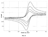
そのようなOECの性質は、種々の原位置外の実験的方法によって判定されてもよい。空気電極に用いられる溶媒におけるOECの溶解性は、OECの濃度を判定するためのLevichおよびCottrellの式の基づく分析と組み合わせた電気分析方法によって、実験的に確認することができる。電池に用いられる溶媒におけるOECの平衡電位は、本明細書では、溶媒とOECとを含む溶液中に浸漬されたガラス状炭素の円盤で得られるサイクリックボルタモグラムにおける酸化波と還元波との間の中間となるように、実験的に画定される。金属酸化物放電生成物とOECとの間の反応を通した酸素ガスの発生は、密閉反応容器の中の電池に用いられるOEC、金属酸化物、および溶媒を混合することによって、ならびに発生したガスの組成を、同じ金属酸化物および溶媒を含有するが候補材料は含有しない、対照容器の組成と比較して、酸素発生反応が起こったか同かを判定することによって、実験的に確認することができる。OECの性質を判定するための原位置外実験のより詳細な説明は、下記の実施例の節で見出すことができる。 The nature of such OEC may be determined by various off-site experimental methods. The solubility of the OEC in the solvent used for the air electrode can be confirmed experimentally by an electroanalytical method combined with an analysis based on the Levich and Cottelell equation to determine the OEC concentration. The equilibrium potential of the OEC in the solvent used in the battery is, as used herein, between the oxidation and reduction waves in a cyclic voltammogram obtained with a glassy carbon disk immersed in a solution containing the solvent and OEC. Experimentally defined to be intermediate. Oxygen gas generation through the reaction between the metal oxide discharge product and the OEC is achieved by mixing the OEC, metal oxide, and solvent used in the battery in the sealed reaction vessel, and the generated gas. Can be confirmed experimentally by comparing the composition of the same with the composition of a control vessel containing the same metal oxide and solvent but no candidate material to determine if an oxygen evolution reaction has occurred. it can. A more detailed description of in situ experiments to determine the nature of OEC can be found in the Examples section below.
酸素発生触媒
図1は、特定の実施形態によるOECの作用原理の一般的な例証を提供する。電池充電中に、セルは、概して、平衡セル電圧よりも高い電圧で動作する。本明細書で使用される場合、「平衡セル電圧」という用語は、セル反応全体と関連付けられる熱力学的参照値から計算することができる量を指す(表2を参照されたい)。この電位範囲内で、OECは、電気化学的に酸化された時に活性化した状態になる。酸化型(OEC+)は、溶液中に拡散し、金属酸化物放電生成物を酸化させて、分子酸素および金属イオンを放出する。金属酸化物の酸化に従って、還元したOECが溶液中に拡散し、再度、電気化学的に酸化させるために利用可能である。理論に拘束されることを望むものではないが、OECは、空気電極表面上で電気化学的に酸化および再酸化されてもよい。結果的に、OECの電気化学的酸化は、OEC+を発生または再生し、金属酸化物放電生成物から空気電極まで電子を移動させる役目をすることができる。図1で例証されるように、主な利益は、金属酸化物の間接的な酸化およびOECの電気化学的再生といった過程に関連し得る。特定の実施形態では、間接的な酸化の機構は、空気電極に直接接触していない、または不十分な電子伝導性を有する金属酸化物放電生成物の効率的な充電を可能にすることができる。対照的に、従来の不均質触媒(図3の303dを参照されたい。以下で詳細に説明する)は、電極表面上の固定場所での電荷移動だけにしか影響を与え得ず、これは、充電過程中に酸素発生反応の効率を改善する触媒の能力を制限する。
本明細書で使用される場合、「ターンオーバー」という用語は、図1で表される1つの触媒サイクルを指し、「ターンオーバー数」という用語は、1モルのOECが触媒的に不活性になる前に酸化させることができる、金属酸化物放電生成物のモル数を指す。図1では、酸化還元対(OEC/OEC+)は、単に相対的酸化状態を表しているだけであり、OECの実際の酸化状態を反映していない。加えて、OECは、セルの動作電圧範囲内で、複数の酸化還元変換を受け得る。 As used herein, the term “turnover” refers to one catalytic cycle represented in FIG. 1, and the term “turnover number” refers to the catalytically inert 1 mol of OEC. Refers to the number of moles of metal oxide discharge product that can be oxidized before becoming. In FIG. 1, the redox couple (OEC / OEC + ) merely represents the relative oxidation state and does not reflect the actual oxidation state of the OEC. In addition, the OEC can undergo multiple redox transformations within the operating voltage range of the cell.
図1で表される反応を進めるための実用的な熱力学的考察は、OECの平衡電位が、平衡セル電圧よりも大きいことである。この電位差は、反応のための熱力学的駆動力を提供する。しかしながら、OECが、平衡セル電圧に可能な限り近い電位で電気化学的に活性化されることが必要になり得る。結果的に、特定の実施形態では、平衡セル電圧より1.5V未満高い、平衡セル電圧より1V未満高い、平衡セル電圧より0.5V未満高い、平衡セル電圧より0.4V未満高い、平衡セル電圧より0.3V未満高い、平衡セル電圧より0.2V未満高い、および平衡セル電圧より0.1V未満高い、を含む、平衡セル電圧から一定の範囲内の平衡電位を有するOECが提供される。選択された金属空気電池の平衡セル電圧については、表2を参照されたい。 A practical thermodynamic consideration for advancing the reaction represented in FIG. 1 is that the OEC equilibrium potential is greater than the equilibrium cell voltage. This potential difference provides a thermodynamic driving force for the reaction. However, it may be necessary for the OEC to be electrochemically activated at a potential as close as possible to the equilibrium cell voltage. Consequently, in certain embodiments, the balanced cell is less than 1.5V above the balanced cell voltage, less than 1V above the balanced cell voltage, less than 0.5V above the balanced cell voltage, and less than 0.4V above the balanced cell voltage. An OEC having an equilibrium potential within a range from the equilibrium cell voltage is provided, including less than 0.3V above the voltage, less than 0.2V above the equilibrium cell voltage, and less than 0.1V above the equilibrium cell voltage. . See Table 2 for the equilibrium cell voltage of the selected metal-air battery.
特定の実施形態では、OECは、多数のサイクルにわたって電池充電過程に関与することが可能である。図1で例証される機構を介して金属空気電池の中を移動させることができる総電荷量は、空気電極中の液体成分の量、液体成分中のOECの濃度、およびOECのターンオーバー数に関連し得る。結果的に、いくつかの実施形態では、100以上、500以上、1000以上、5000以上、および10,000以上のターンオーバー数を含む、高ターンオーバー数を伴うOECが提供される。OECのターンオーバー数にはいかなる上限もないが、10,000,000を超えるターンオーバー数は、概して、1,000サイクルのサイクル寿命に到達することを必要としない。 In certain embodiments, the OEC can participate in the battery charging process over a number of cycles. The total amount of charge that can be moved through the metal-air battery via the mechanism illustrated in FIG. 1 is the amount of liquid component in the air electrode, the concentration of OEC in the liquid component, and the turnover number of OEC. May be related. Consequently, in some embodiments, OECs with high turnover numbers are provided, including turnover numbers of 100 or more, 500 or more, 1000 or more, 5000 or more, and 10,000 or more. Although there is no upper limit to the turnover number of the OEC, turnover numbers exceeding 10,000,000 generally do not require reaching a cycle life of 1,000 cycles.
同様に、いくつかの実施形態では、本発明は、0.1M以上、0.5M以上、1.0M以上、および2.0M以上の溶解性を含む、電解質の液体成分への高い溶解性を伴うOECを提供する。特定の実施形態では、液体相OECはまた、共溶媒または唯一の電解質溶媒としての役割を果たすこともできる。したがって、OECの溶解性にはいかなる上限もないが、概して、10Mの溶解性を超えない。 Similarly, in some embodiments, the present invention provides high solubility of electrolytes in liquid components, including solubility of 0.1M or higher, 0.5M or higher, 1.0M or higher, and 2.0M or higher. Provide accompanying OEC. In certain embodiments, the liquid phase OEC can also serve as a co-solvent or sole electrolyte solvent. Thus, there is no upper limit on the solubility of the OEC, but generally does not exceed the solubility of 10M.
数多くの望ましい性質を具現化する化学的分類およびOECの構造を、本明細書で説明する。主な分類は、1)無機アニオンと、3)芳香族化合物と、3)キノンおよびキノイドと、4)遷移金属錯体とを含む。 Chemical classifications and OEC structures that embody a number of desirable properties are described herein. The main classifications include 1) inorganic anions, 3) aromatic compounds, 3) quinones and quinoids, and 4) transition metal complexes.
種々の種類の無機アニオンは、OECを誘引性にする、化学的および電気化学的性質を有する。具体的には、特定のハロゲン化物、擬ハロゲン化物、およびポリオキソメタレートは、金属空気電池充電に関連する電位範囲内でそれらの酸化還元状態の大部分の高い安定性のため、OECとして使用するのに好適である。例示的な無機アニオンには、以下が挙げられるが、それらに限定されない。
1)Cl-、Br-、I-、を含むハロゲン化物。
2)シアン化物、シアネート、イソシアネート、ロダン化物(すなわち、チオシアネートおよびイソチオシアネート)、セレノロダン化物(selenorhodanide)、テルロロダン化物(tellurorhodanide)、およびアジド等の、対応する疑ハロゲン基のアニオン(または官能基)を含む擬ハロゲン化物。
3)Keggin型アニオンと、Dawson型アニオンとを含むポリオキソメタレート。
Various types of inorganic anions have chemical and electrochemical properties that make OEC attractive. Specifically, certain halides, pseudohalides, and polyoxometalates are used as OEC because of the high stability of most of their redox states within the potential range associated with metal-air battery charging. It is suitable for doing. Exemplary inorganic anions include, but are not limited to:
1) A halide containing Cl − , Br − and I − .
2) Corresponding anions (or functional groups) of the corresponding pseudohalogen groups, such as cyanides, cyanates, isocyanates, rhodandides (ie thiocyanates and isothiocyanates), selenorhodanides, tellurorhodanides, and azides. Contains pseudohalides.
3) Polyoxometalates containing Keggin type anions and Dawson type anions.
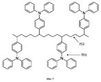
芳香族化合物は、それらのOECとしての使用を動機付ける、種々の性質を有する。芳香族化合物は、4n+2電子則(ヒュッケル則)に一致する、頑健な循環構造である。それらは、酸化および還元に応じて幾何学的歪を受ける必要がないという事実のため、概して、迅速な電子移動を可能にする、平坦な構造を有する。芳香族分子の安定性は、電気化学的可逆性と非常に相関する。OECとして使用するための芳香族化合物には、N、O、P、S、Se、Te、またはそれらの任意の組み合わせを含有する芳香族ヘテロ環が挙げられる。例示的な芳香族化合物には、以下が挙げられるが、それらに限定されない。
1)置換されたトリアリールアミン:
2)置換されたフェニレンジアミン:
3)置換された芳香族ポリアリールアミン:
4)置換されたフェノチアジン:
5)置換された1,2−ビス(3−アルキル−2,3−ジヒドロ−1,3−ベンゾチアゾール−2−イリデン)ヒドラジン:
式中、R1〜R10は独立して、置換された又は非置換の、C1−C10アルキル基、アリール基、C4−C8炭素環式基、C4−C8複素環式基の任意の組み合わせから選択され、ヘテロ原子は、N、O、S、Se、Te、任意のハロゲン(例えば、F、Cl、Br、I、At)、または任意の短分子(例えば、CR2、CR、CR3、OR、Ph、O−Ph、CHO、CN、COR、CO2R、COSH、CS2H、SR、CSSH、NR、NR2、NO2、OH、OPO3H2、OSO3H、PO3H2、SO2、SO3H、式中、Rは、R1〜R10について定義されたものである)のうちの1つ以上である。
6)置換されたカルバゾール:
式中、R1〜R8は独立して、置換された又は非置換の、C1−C10アルキル基、アリール基、C4−C8炭素環式基、C4−C8複素環式基の任意の組み合わせから選択され、ヘテロ原子は、N、O、S、Se、Te、任意のハロゲン(例えば、F、Cl、Br、I、At)、または任意の短分子(例えば、CR2、CR、CR3、OR、Ph、O−Ph、CHO、CN、COR、CO2R、COSH、CS2H、SR、CSSH、NR、NR2、NO2、OH、OPO3H2、OSO3H、PO3H2、SO2、SO3H、式中、Rは、R1〜R8について定義されたものである)のうちの1つ以上である。
7)置換されたテトラチアフルバレン:
式中、R1〜R8は独立して、置換された又は非置換の、C1−C10アルキル基、アリール基、C4−C8炭素環式基、C4−C8複素環式基の任意の組み合わせから選択され、ヘテロ原子は、N、O、S、Se、Te、任意のハロゲン(例えば、F、Cl、Br、I、At)、または任意の短分子(例えば、CR2、CR、CR3、OR、Ph、O−Ph、CHO、CN、COR、CO2R、COSH、CS2H、SR、CSSH、NR、NR2、NO2、OH、OPO3H2、OSO3H、PO3H2、SO2、SO3H、式中、Rは、R1〜R8について定義されたものである)のうちの1つ以上である。
8)置換されたチオフェン:
式中、R1〜R8は独立して、置換された又は非置換の、C1−C10アルキル基、アリール基、C4−C8炭素環式基、C4−C8複素環式基の任意の組み合わせから選択され、ヘテロ原子は、N、O、S、Se、Te、任意のハロゲン(例えば、F、Cl、Br、I、At)、または任意の短分子(例えば、CR2、CR、CR3、OR、Ph、O−Ph、CHO、CN、COR、CO2R、COSH、CS2H、SR、CSSH、NR、NR2、NO2、OH、OPO3H2、OSO3H、PO3H2、SO2、SO3H、式中、Rは、R1〜R8について定義されたものである)のうちの1つ以上である。nは、0〜5の範囲であってもよい。
9)置換されたチアントレンおよびフェノキサチイン:
式中、R1〜R8は独立して、置換された又は非置換の、C1−C10アルキル基、アリール基、C4−C8炭素環式基、C4−C8複素環式基の任意の組み合わせから選択され、ヘテロ原子は、N、O、S、Se、Te、任意のハロゲン(例えば、F、Cl、Br、I、At)、または任意の短分子(例えば、CR2、CR、CR3、OR、Ph、O−Ph、CHO、CN、COR、CO2R、COSH、CS2H、SR、CSSH、NR、NR2、NO2、OH、OPO3H2、OSO3H、PO3H2、SO2、SO3H、式中、Rは、R1〜R8について定義されたものである)のうちの1つ以上である。
10)置換されたジおよびポリアルコキシベンゼン:
11)置換されたホスフィンイミド:
12)置換された多環芳香族化合物:
式中、R1〜R10は独立して、置換された又は非置換の、C1−C10アルキル基、アリール基、C4−C8炭素環式基、C4−C8複素環式基の任意の組み合わせから選択され、ヘテロ原子は、N、O、S、Se、Te、任意のハロゲン(例えば、F、Cl、Br、I、At)、または任意の短分子(例えば、CR2、CR、CR3、OR、Ph、O−Ph、CHO、CN、COR、CO2R、COSH、CS2H、SR、CSSH、NR、NR2、NO2、OH、OPO3H2、OSO3H、PO3H2、SO2、SO3H、式中、Rは、R1〜R10について定義されたものである)のうちの1つ以上である。nは、1〜10の範囲であってもよい。
13)置換されたジアジン:
1) Substituted triarylamine:
2) Substituted phenylenediamine:
3) Substituted aromatic polyarylamine:
4) Substituted phenothiazine:
5) Substituted 1,2-bis (3-alkyl-2,3-dihydro-1,3-benzothiazol-2-ylidene) hydrazine:
In which R 1 to R 10 are independently substituted or unsubstituted C 1 -C 10 alkyl groups, aryl groups, C 4 -C 8 carbocyclic groups, C 4 -C 8 heterocyclic groups. The heteroatom is selected from any combination of groups, and the heteroatom can be N, O, S, Se, Te, any halogen (eg, F, Cl, Br, I, At), or any short molecule (eg, CR 2 , CR, CR 3, OR, Ph, O-Ph, CHO, CN, COR, CO 2 R, COSH, CS 2 H, SR, CSSH, NR,
6) Substituted carbazole:
In which R 1 to R 8 are independently substituted or unsubstituted C 1 -C 10 alkyl groups, aryl groups, C 4 -C 8 carbocyclic groups, C 4 -C 8 heterocyclic groups. The heteroatom is selected from any combination of groups, and the heteroatom can be N, O, S, Se, Te, any halogen (eg, F, Cl, Br, I, At), or any short molecule (eg, CR 2 , CR, CR 3, OR, Ph, O-Ph, CHO, CN, COR, CO 2 R, COSH, CS 2 H, SR, CSSH, NR,
7) Substituted tetrathiafulvalene:
In which R 1 to R 8 are independently substituted or unsubstituted C 1 -C 10 alkyl groups, aryl groups, C 4 -C 8 carbocyclic groups, C 4 -C 8 heterocyclic groups. The heteroatom is selected from any combination of groups, and the heteroatom can be N, O, S, Se, Te, any halogen (eg, F, Cl, Br, I, At), or any short molecule (eg, CR 2 , CR, CR 3, OR, Ph, O-Ph, CHO, CN, COR, CO 2 R, COSH, CS 2 H, SR, CSSH, NR,
8) Substituted thiophene:
In which R 1 to R 8 are independently substituted or unsubstituted C 1 -C 10 alkyl groups, aryl groups, C 4 -C 8 carbocyclic groups, C 4 -C 8 heterocyclic groups. The heteroatom is selected from any combination of groups, and the heteroatom can be N, O, S, Se, Te, any halogen (eg, F, Cl, Br, I, At), or any short molecule (eg, CR 2 , CR, CR 3, OR, Ph, O-Ph, CHO, CN, COR, CO 2 R, COSH, CS 2 H, SR, CSSH, NR,
9) Substituted thianthrene and phenoxathiin:
In which R 1 to R 8 are independently substituted or unsubstituted C 1 -C 10 alkyl groups, aryl groups, C 4 -C 8 carbocyclic groups, C 4 -C 8 heterocyclic groups. The heteroatom is selected from any combination of groups, and the heteroatom can be N, O, S, Se, Te, any halogen (eg, F, Cl, Br, I, At), or any short molecule (eg, CR 2 , CR, CR 3, OR, Ph, O-Ph, CHO, CN, COR, CO 2 R, COSH, CS 2 H, SR, CSSH, NR,
10) Substituted di- and polyalkoxybenzenes:
11) Substituted phosphine imide:
12) Substituted polycyclic aromatic compounds:
In which R 1 to R 10 are independently substituted or unsubstituted C 1 -C 10 alkyl groups, aryl groups, C 4 -C 8 carbocyclic groups, C 4 -C 8 heterocyclic groups. The heteroatom is selected from any combination of groups, and the heteroatom can be N, O, S, Se, Te, any halogen (eg, F, Cl, Br, I, At), or any short molecule (eg, CR 2 , CR, CR 3, OR, Ph, O-Ph, CHO, CN, COR, CO 2 R, COSH, CS 2 H, SR, CSSH, NR,
13) Substituted diazine:
キノンおよびキノイドは、OECの関心の電位範囲で調整可能な酸化還元電位および安定した酸化還元状態を有する、有機化合物である。例示的なキノンおよびキノイドには、以下が挙げられるが、それらに限定されない。
遷移金属錯体は、有機リガンドに配位した1つ以上の遷移金属中心から成る。遷移金属錯体は、遷移金属中心との高速な外圏電子移動、および有機リガンドによって与えられる可溶化または安定化性質のため、OECとして使用するのに好適である。例示的な遷移金属錯体には、以下が挙げられるが、それらに限定されない。
式中、R1〜R16は独立して、置換された又は非置換の、C1−C10アルキル基、アリール基、C4−C8炭素環式基、C4−C8複素環式基の任意の組み合わせから選択され、ヘテロ原子は、N、O、S、Se、Te、任意のハロゲン(例えば、F、Cl、Br、I、At)、または任意の短分子(例えば、CR2、CR、CR3、OR、Ph、O−Ph、CHO、CN、COR、CO2R、COSH、CS2H、SR、CSSH、NR、NR2、NO2、OH、OPO3H2、OSO3H、PO3H2、SO2、SO3H、式中、Rは、R1〜R16について定義されたものである)のうちの1つ以上である。
Transition metal complexes consist of one or more transition metal centers coordinated to an organic ligand. Transition metal complexes are suitable for use as OEC because of the fast outer sphere electron transfer with transition metal centers and the solubilizing or stabilizing properties provided by organic ligands. Exemplary transition metal complexes include, but are not limited to:
In which R 1 to R 16 are independently substituted or unsubstituted C 1 -C 10 alkyl groups, aryl groups, C 4 -C 8 carbocyclic groups, C 4 -C 8 heterocyclic groups. The heteroatom is selected from any combination of groups, and the heteroatom can be N, O, S, Se, Te, any halogen (eg, F, Cl, Br, I, At), or any short molecule (eg, CR 2 , CR, CR 3, OR, Ph, O-Ph, CHO, CN, COR, CO 2 R, COSH, CS 2 H, SR, CSSH, NR,
特定の実施形態では、上記に列記したもの等の有機化合物は、OECとして使用するのに好適である。いくつかの実施形態では、それらの物理的および電気化学的性質は、合成を通して「調整可能」である。例えば、種々の機能の置換を通して、分子のHOMOおよびLUMOレベルを操作することが可能であり得、それによって酸化および還元される電位に影響を及ぼす。酸化電位を低くするための一般的な戦略は、電子供与性のR基(すなわち、NMe2、SMe、Me等)の使用を含むことができる一方で、還元電位は、概して、電子吸引性のR基(すなわち、CN、NO2等)を導入することによって高くすることができる。加えて、長い炭化水素および分鎖した炭化水素鎖の置換は、ある程度の分子の溶解性の制御を可能にすることができ、広範囲の溶媒と互換性があり得る。さらに、所与のOEC(例えば、芳香族コアを有するOEC)上の種々の地点でのR基置換によって、しばしば、OECの電気化学的および化学的安定性に影響を及ぼすことがあり得る。これらの望ましい性質を伴ういくつかの例示的なR基を、下記の表3に列記する。1つ以上のR基は、組み合わせて任意の基から選択することができる。ハロゲン(X)は、F、Cl、またはBrおよびそれらの組み合わせを含んでもよい。
1つ以上の実施形態では、充電式金属空気電池は、自由拡散するOECと、主鎖の一部として、またはペンダント基として、ポリマー構造の中に組み込まれるOECとの組み合わせを含むことができる。「ポリマー構造」という用語は、本明細書で使用される場合、ポリマー鎖、さらにはオリゴマーまたはデンドリマーを指す。図6および図7は、OECがポリマー構造に結合した酸化還元中心(黒丸で示される)である、実施形態を例証する。ポリマー構造は、電極表面に結合し得るか、電解質を伴う溶液中に自由に混合することができるか、または両方である。理論に拘束されることを望むものではないが、図6に示されるように、放電生成物(601)、OEC(602)、および空気電極(604)の間の電荷伝搬は、OECの拡散、電子ホッピング、およびOEC酸化還元中心(603)の中での自己交換の組み合わせを通して起こり得ることを強調しておく。OECを組み込んだポリマー構造の包含は、空気電極の中のOEC酸化還元中心の密度を増加させることができ、空気電極と放電生成物との間の電荷伝搬の速度を向上させ得る。図7は、特定の実施例について、ペンダントトリアリールアミンを伴う分子(例えば、ポリマー鎖)を例証する。 In one or more embodiments, rechargeable metal-air batteries can include a combination of free-diffusing OEC and OEC incorporated into the polymer structure as part of the backbone or as a pendant group. The term “polymer structure” as used herein refers to polymer chains, as well as oligomers or dendrimers. FIGS. 6 and 7 illustrate embodiments in which the OEC is a redox center (indicated by a black circle) attached to the polymer structure. The polymer structure can be bonded to the electrode surface, can be freely mixed in a solution with an electrolyte, or both. While not wishing to be bound by theory, as shown in FIG. 6, charge propagation between the discharge product (601), the OEC (602), and the air electrode (604) is due to OEC diffusion, It is emphasized that this can occur through a combination of electron hopping and self-exchange within the OEC redox center (603). Inclusion of a polymer structure incorporating OEC can increase the density of OEC redox centers in the air electrode and can increase the rate of charge propagation between the air electrode and the discharge product. FIG. 7 illustrates molecules (eg, polymer chains) with pendant triarylamines for certain examples.
充電式Li−空気電池
充電式金属空気電池は、種々の負電極材料によって調製することができる。Liは、比較的に高い電気陽性および低い分子量を有するので、Li−空気電池は、高容量を必要とする応用のための有望な技術である。非プロトン電解質を含有するLi−空気電池は、とりわけ高い理論セル電圧および容量を有する。以下のセルの反応によれば、この種類のLi−空気電池は、3,459Wh/kgの理論的比エネルギー、および7,955Wh/Lのエネルギー密度を有する。
![]()
![]()
簡潔にするため、本明細書は、Li−空気電池に関して説明する。これらの説明は、例証の目的で提供されるものであり、本発明をLi−空気電池に限定するものとして解釈するべきでない。 For brevity, this specification will be described with respect to a Li-air battery. These descriptions are provided for illustrative purposes and should not be construed as limiting the invention to Li-air batteries.
図2を参照すると、例示的なLi−空気電池は、Li負電極(201)と、空気正電極(203)と、負および性電極間でイオンを伝導するように構成される非プロトン電解質(202)と、を備える。Li電極は、Liイオンを放出して、取り込むことが可能である材料を含む。空気電極は、部分的に電解質(202)で満たされ、外部貯留部から酸素にアクセスすることが可能である、多孔質材料(203a)を含む。電池が接続された時に、外部負荷、Liイオン、および電子は、Li電極(201)から空気電極(203)に流れる。空気電極(203)に進入する酸素ガス(O2)は、最初に、電解質(202)の中に溶解し、次いで、空気電極(203)の表面に拡散して、そこで電気化学的に還元される。Liイオンと還元された酸素との間の反応は、金属酸化物放電生成物(203b)を空気電極の孔の中に堆積させる。概して、放電生成物は、他の生成物も形成し得るが、Li2O2およびLi2Oを含むと考えられる。 With reference to FIG. 2, an exemplary Li-air battery includes an aprotic electrolyte (201) configured to conduct ions between a Li negative electrode (201), an air positive electrode (203), and negative and sex electrodes. 202). The Li electrode includes a material that can release and capture Li ions. The air electrode includes a porous material (203a) that is partially filled with electrolyte (202) and is accessible to oxygen from an external reservoir. When the battery is connected, external loads, Li ions, and electrons flow from the Li electrode (201) to the air electrode (203). Oxygen gas (O 2 ) entering the air electrode (203) is first dissolved in the electrolyte (202) and then diffuses to the surface of the air electrode (203) where it is electrochemically reduced. The The reaction between the Li ions and the reduced oxygen deposits the metal oxide discharge product (203b) in the pores of the air electrode. In general, discharge products are believed to include Li 2 O 2 and Li 2 O, although other products may also form.
比較のため、図3は、従来の不均質触媒(303d)を含有するLi−空気電池の充電過程を表す。充電電流をセルに印加することによって、空気電極(303)の中の放電生成物(303b)が酸化され、酸素ガス、Liイオン、および電子を放出し、これらは、それぞれ、外部貯留部に放出され、電解質を通過し、また、外部回路を通過する。放電生成物(303b)の酸化は、空気電極表面上の不均質反応で起こる。空気電極表面上の不均質触媒(303d)は、空気電極表面に直接面している放電生成物(303b)の部分だけに接触する。不均質触媒(303d)は、界面領域の外側にある生成物の酸化には関与しないことが分かる。同様に、電極表面との電子接触を失った放電生成物(303c)の部分は、全く酸化されず、電池サイクル中の不可逆的容量損失を助長する。 For comparison, FIG. 3 represents the charging process of a Li-air battery containing a conventional heterogeneous catalyst (303d). By applying the charging current to the cell, the discharge product (303b) in the air electrode (303) is oxidized and releases oxygen gas, Li ions, and electrons, which are each released to the external reservoir. Through the electrolyte and through an external circuit. Oxidation of the discharge product (303b) occurs in a heterogeneous reaction on the air electrode surface. The heterogeneous catalyst (303d) on the air electrode surface contacts only the portion of the discharge product (303b) that directly faces the air electrode surface. It can be seen that the heterogeneous catalyst (303d) does not participate in the oxidation of the product outside the interfacial region. Similarly, the portion of the discharge product (303c) that has lost electronic contact with the electrode surface is not oxidized at all and promotes irreversible capacity loss during the battery cycle.
ここで、図4を参照すると、OEC(403d)が電解質(402)の液体相に溶解して、空気電極(403)の孔の中に含有された、Li−空気電池が示される。電解質溶液中のOECの濃度は、限定されないが、一般的に、0.01mM〜2.0Mの範囲である。可溶OECs(403d)は、放電生成物(403b)との改善された接触を有し、空気電極表面(403a)から電子的に遮断された放電生成物を酸化させることが可能であり、それによって、不可逆的容量損失を低減する。 Referring now to FIG. 4, there is shown a Li-air battery in which OEC (403d) is dissolved in the liquid phase of the electrolyte (402) and contained in the pores of the air electrode (403). The concentration of OEC in the electrolyte solution is not limited, but is generally in the range of 0.01 mM to 2.0M. Soluble OECs (403d) have improved contact with the discharge product (403b) and are capable of oxidizing the discharge product that is electronically blocked from the air electrode surface (403a), Reduces irreversible capacity loss.
特定の動作理論に拘束されることを望むものではないが、Li−空気電池システムの中の金属酸化物放電生成物(403bおよび403c)の性質について、いくつか概論することができる。まず、概して、これらの金属酸化物放電生成物(403bおよび403c)は、大部分の極性非プロトン溶媒に非常に不溶性であり、結果として、空気電極孔(403)の中に固体として蓄積することが観察される。さらに、概して、これらの金属酸化物放電生成物(403bおよび403c)は、電子的に絶縁しているか、または非常に抵抗性がある。最後に、空気電極(403)の中の固体材料(403bおよび403c)の形成は、容量変化、電解質(402)の排除、電子的接続性の低下を含む空気電極(403)の電子微細組織に対する変化を引き起こす。これらの性質は、従来のLi−空気電池の性能限界の一部に関連し得る。対照的に、自由に拡散するOEC(403d)は、空気電極(403)と、絶縁および/または電子的に遮断された放電生成物(403c)との間の電荷伝搬のための経路を提供する。 While not wishing to be bound by any particular theory of operation, some general considerations can be given to the nature of the metal oxide discharge products (403b and 403c) in Li-air battery systems. First, in general, these metal oxide discharge products (403b and 403c) are very insoluble in most polar aprotic solvents, and as a result, accumulate as solids in the air electrode holes (403). Is observed. Furthermore, in general, these metal oxide discharge products (403b and 403c) are either electronically isolated or very resistive. Finally, the formation of the solid material (403b and 403c) in the air electrode (403) is against the electronic microstructure of the air electrode (403), including capacity changes, the elimination of electrolyte (402), reduced electronic connectivity. Cause change. These properties can be related to some of the performance limitations of conventional Li-air batteries. In contrast, the freely diffusing OEC (403d) provides a path for charge propagation between the air electrode (403) and the insulated and / or electronically blocked discharge product (403c). .
特定の実施形態では、OECは、負電極(401)に対して不安定であり得る。そのような事例では、図5に示されるように、OEC輸送に対して不透過性である第2の電解質相(502a)が利用されてもよい。半透過性電解質相(502a)は、Li+に対して透過性であってもよく、OECに対して実質的にまたは完全に不透過性であってもよく、また、他の種に対しては透過性または不透過性であってもよい。いくつかの実施形態では、この第2の電解質相(502a)は、電解質溶媒または電解質添加剤とともに形成された、固体電解質中間相(SEI)とすることができる。SEIは、電極と電解質との間の反応に起因して負電極の表面上に形成する、相である。他の実施形態では、第2の電解質相は、ガラスセラミックまたはポリマーを含む。半透過性電解質相(502a)は、OECが負電極に接触することを防止し、それによって、電池内のOECの動作寿命を延ばす。 In certain embodiments, the OEC can be unstable with respect to the negative electrode (401). In such cases, a second electrolyte phase (502a) that is impermeable to OEC transport may be utilized, as shown in FIG. The semi-permeable electrolyte phase (502a) may be permeable to Li + , may be substantially or completely impermeable to OEC, and may be against other species. May be permeable or impermeable. In some embodiments, this second electrolyte phase (502a) can be a solid electrolyte intermediate phase (SEI) formed with an electrolyte solvent or electrolyte additive. SEI is a phase that forms on the surface of the negative electrode due to the reaction between the electrode and the electrolyte. In other embodiments, the second electrolyte phase comprises a glass ceramic or polymer. The semi-permeable electrolyte phase (502a) prevents the OEC from contacting the negative electrode, thereby extending the operating life of the OEC in the battery.
特定の実施形態では、非プロトン性電解質は、Liイオンが負電極と空気電極との間を動くための連続する経路を提供する。これらの要件の他に、1つ以上の相を含有する電解質の数多くの構成および組成物が用いられてもよい。特定の実施形態では、電解質は、極性非プロトン溶媒と、Li塩とを含む。Li−空気電池のための例示的な極性非プロトン溶媒は、エーテル、グリム、炭酸塩、ニトリル、アミド、アミン、有機硫黄溶媒、有機リン溶媒、有機ケイ素溶媒、イオン液体、フッ素化溶媒、およびこれらの組み合わせを含むことができる。Li塩は、典型的に、0.1M〜2Mの範囲の濃度で溶媒中に存在することができる。例示的なリチウム塩には、LiClO4、LiPF6、LiBf6、LiBOB、LiTFS、およびLiTFSIが挙げられる。 In certain embodiments, the aprotic electrolyte provides a continuous path for Li ions to move between the negative and air electrodes. In addition to these requirements, numerous configurations and compositions of electrolytes containing one or more phases may be used. In certain embodiments, the electrolyte comprises a polar aprotic solvent and a Li salt. Exemplary polar aprotic solvents for Li-air batteries are ether, glyme, carbonate, nitrile, amide, amine, organic sulfur solvent, organophosphorus solvent, organosilicon solvent, ionic liquid, fluorinated solvent, and these Can be included. The Li salt can typically be present in the solvent at a concentration ranging from 0.1M to 2M. Exemplary lithium salts include LiClO 4 , LiPF 6 , LiBf 6 , LiBOB, LiTFS, and LiTFSI.
Li−空気電池のための溶媒の選択を判定する1つの重要な因子は、Li2O2、Li2O、および空気電極の中に形成されるLiO2等の中間体に対する溶媒の安定性である。Liイオン電池で一般的に用いられる数多くの極性非プロトン溶媒は、これらの材料に対して不安定である。空気電極の動作中の溶媒の分解は、電池のサイクル寿命および容量を大幅に制限する可能性がある。Li−空気電池溶媒のための特に安定した化学的機能は、N−アルキルで置換されたアミド、ラクタム、およびエーテルを含む。 One important factor in determining the choice of solvent for Li-air batteries is the stability of the solvent to intermediates such as Li 2 O 2 , Li 2 O, and LiO 2 formed in the air electrode. is there. Many polar aprotic solvents commonly used in Li-ion batteries are unstable to these materials. Solvent degradation during operation of the air electrode can severely limit the cycle life and capacity of the battery. Particularly stable chemical functions for Li-air battery solvents include amides, lactams, and ethers substituted with N-alkyl.
OECと組み合わせて相乗的性能改善を可能にし得る種々の添加剤を、電解質に組み込んでもよい。いくつかの例示的な添加剤には、アニオン受容体、カチオン受容体、およびSEI形成剤が挙げられる。アニオン受容体およびカチオン受容体は、それぞれ、アニオンおよびカチオンを選択的に配位する能力を有する化合物であり、電解質中のそれらの包含は、金属酸化物放電生成物の溶解性を強化し得る。この強化された溶解性は、OECとの反応速度を改善し得る。SEI形成剤は、SEIの性質および化学的組成物を調整するために電解質に加えられる材料である。特定のSEI形成剤は、結果として生じるSEIが負電極とOECとの間の有害な反応を阻害するので、OECと組み合わせて選択してもよい。 Various additives that can be combined with OEC to enable synergistic performance improvements may be incorporated into the electrolyte. Some exemplary additives include anion receptors, cation receptors, and SEI formers. Anion receptors and cation receptors are compounds having the ability to selectively coordinate anions and cations, respectively, and their inclusion in the electrolyte can enhance the solubility of the metal oxide discharge product. This enhanced solubility can improve the reaction rate with OEC. SEI formers are materials that are added to the electrolyte to adjust the properties and chemical composition of the SEI. Certain SEI formers may be selected in combination with OEC because the resulting SEI inhibits the deleterious reaction between the negative electrode and the OEC.
概して、高Li容量を伴う負電極材料は、高容量空気電極と連結することが好ましくなり得る。例示的な金属電極材料には、Li金属(例えば、Li箔および基板上に堆積させたLi)、Li合金(例えば、LiおよびSi、LiおよびSn、LiおよびSb、LiおよびAl、LiおよびMg、LiおよびBi、またはそれらの任意の組み合わせを含む合金)、Li挿入材料(例えば、グラファイト)、ならびにLi転換反応材料(例えば、金属酸化物、金属水素化物、金属窒化物、金属フッ化物、金属硫化物、金属アンチモン化物、および金属リン化物)が挙げられる。「転換反応材料」という用語は、以下のように法則化される、リチウムと遷移金属との間の電気化学的反応に関連する反応性の概念を指す。
![]()
![]()
空気電極は、Liイオンおよび酸素のための輸送経路を維持すること可能である他に、放電生成物が堆積することができる容積を与えることができるが、それ以外は、構造および材料組成物に関して制限しない、電子伝導性材料とすることができる。例示的な空気電極材料には、PTFEまたはPVDF等の好適な結合剤と組み合わせられる多孔質炭素が挙げられる。他の金属空気電池システムと同様に、空気電極のための酸素は、周囲環境から得ることができるが、貯蔵タンクまたは任意の他の供給源から酸素が供給されてもよい。 In addition to being able to maintain a transport path for Li ions and oxygen, the air electrode can provide a volume in which discharge products can be deposited, but otherwise with respect to structure and material composition An electronically conductive material can be used without limitation. Exemplary air electrode materials include porous carbon combined with a suitable binder such as PTFE or PVDF. As with other metal-air battery systems, oxygen for the air electrode can be obtained from the ambient environment, but oxygen may be supplied from a storage tank or any other source.
空気電極の製造
リチオ化された負電極材料は、酸素および/または水と反応し、したがって、費用のかかる、または煩雑な取り扱い方法が必要になる可能性があるので、特定の種類の負不電極材料を脱リチオ化された状態で電池の中に組み立てることができる。例えば、これは、Liイオン電池に一般的に用いられるグラファイト陽極の場合であり得るが、Li合金、Li転換反応電極、およびリチウム金属自体等の数多くの高容量材料にも当てはまる。
Production of air electrodes Lithiated negative electrode materials react with oxygen and / or water and therefore may require costly or cumbersome handling methods, so certain types of negative electrode materials The material can be assembled into a battery in a delithiated state. For example, this may be the case for graphite anodes commonly used in Li-ion batteries, but also applies to many high capacity materials such as Li alloys, Li conversion reaction electrodes, and lithium metal itself.
空気電極をこれらの負電極材料と連結するためには、高質量比の金属酸化物放電生成物を含有する、放電済みの状態で製造される空気電極を完全に充電することが望ましくなり得る。これまで、例えば20重量%を超えるLi2O2といった、実用目的で十分に高い金属酸化物放電生成物負荷を伴って製造された空気電極を充電することは困難であることが示されてきた。所望される数のサイクルにわたって予想される不可逆的容量損失を補うために、負電極の容量に対して、過剰な金属酸化物放電生成物が所望され得る。従来のLi−空気電池では、高い生成物負荷時に金属酸化物放電生成物と空気電極との間に不十分な電子的接触があり得、これは、早期に電池を陽極の電圧限界に到達させ得る。対照的に、OECの提供は、空気電極との直接的な電子的接触を維持する必要がないので、より大量の金属酸化物放電生成物を効率的に充電することを可能にすることができる。したがって、OECを含有する空気電極は、より高い生成物負荷を有して製造してもよく、その結果、空気電極の、脱リチオ化された状態で製造される負電極材料との実用的な連結を促進する。 In order to couple the air electrode with these negative electrode materials, it may be desirable to fully charge an air electrode manufactured in a discharged state that contains a high mass ratio of metal oxide discharge products. Heretofore, it has been shown that it is difficult to charge an air electrode manufactured with a metal oxide discharge product load high enough for practical purposes, for example, Li 2 O 2 exceeding 20 wt%. . To compensate for the irreversible capacity loss expected over the desired number of cycles, excess metal oxide discharge product may be desired relative to the capacity of the negative electrode. In conventional Li-air batteries, there can be insufficient electronic contact between the metal oxide discharge product and the air electrode at high product loads, which causes the battery to reach the anode voltage limit early. obtain. In contrast, the provision of OEC can enable more large amounts of metal oxide discharge products to be efficiently charged because there is no need to maintain direct electronic contact with the air electrode. . Thus, an air electrode containing OEC may be manufactured with a higher product load, so that the air electrode is practical with the negative electrode material manufactured in the delithiated state. Promote consolidation.
以下の実施例は、特定の態様および実施形態を例証することを意図したものであり、本発明を任意の特定の方法に限定するものとして解釈するべきではない。 The following examples are intended to illustrate certain aspects and embodiments, and should not be construed as limiting the invention to any particular method.
比較実施例
比較の目的で、この実施例は、Li2O2および適切な電解質を含有する、事前に製造した「放電済みの」空気電極とともに組み立てた、Li−空気電池の充電を例証する。この比較実施例のLi−空気電池は、OECを含有しない。60重量%の乳濁液を、200mLのイソプロパノール/H2O(1:2、v/v)中に懸濁したSuper Pカーボンブラックと機械式回転装置で5分間混合することによって、Super P/PTFE粉末を調製した。溶媒は、最初にロータリ蒸発器によって、次に2日間80℃で真空乾燥することによって、2ステップで除去した。乾燥ペーストは、90重量%のSuper Pおよび10重量%のPTFEから成る微粉末を形成するために、混合機で粉末化した。
Comparative Example For comparative purposes, this example illustrates the charging of a Li-air battery assembled with a pre-manufactured “discharged” air electrode containing Li 2 O 2 and a suitable electrolyte. The Li-air battery of this comparative example does not contain OEC. By mixing 60% by weight of the emulsion with Super P carbon black suspended in 200 mL of isopropanol / H 2 O (1: 2, v / v) for 5 minutes on a mechanical rotator, Super P / PTFE powder was prepared. The solvent was removed in two steps, first by a rotary evaporator and then by vacuum drying at 80 ° C. for 2 days. The dry paste was pulverized with a blender to form a fine powder consisting of 90 wt% Super P and 10 wt% PTFE.
放電済みの空気電極は、以下のように製造した。10mgのSuper P/PTFE粉末、および10mgのLi2O2粉末を含有する混合物を調製し、2トンで10分間、直径7/16インチ(約11.1mm)のAlメッシュ(200メッシュ)上に乾燥プレスした。過剰な電極材料は、縁部からピンセットで除去した。完成した空気電極およびAlメッシュのアセンブリを計量し、Li2O2の質量に基づいてLi2O2の電気化学当量(Qtheo)を計算した。テトラエチレングリコールジメチルエーテル(テトラグリム)および0.5Mのリチウムビス(トリフルオロメタンスルホニル)イミド(LiTFSI)から成る電解質を、O2が1ppm未満でH2Oが1ppm未満のArを満たしたグローブボックスの中で調製した。 The discharged air electrode was manufactured as follows. A mixture containing 10 mg of Super P / PTFE powder and 10 mg of Li 2 O 2 powder was prepared and placed on 7/16 inch (about 11.1 mm) diameter Al mesh (200 mesh) at 2 tons for 10 minutes. Dry pressed. Excess electrode material was removed from the edge with tweezers. The completed air electrode and Al mesh assembly was weighed and the Li 2 O 2 electrochemical equivalent (Qtheo) calculated based on the mass of Li 2 O 2 . An electrolyte consisting of tetraethylene glycol dimethyl ether (tetraglyme) and 0.5 M lithium bis (trifluoromethanesulfonyl) imide (LiTFSI) in a glove box filled with Ar with less than 1 ppm O 2 and less than 1 ppm H 2 O. It was prepared with.
Swagelok試験セルは、以下のように、Arを満たしたグローブボックスの中で組み立てた。Li金属電極(厚さ200μm、および直径7/16インチ(約11.1mm))を、Swagelok治具の内部チャンバの基部でも機能するステンレス鋼電流コレクタの最上部に固定した。2つのWhatman GF/Dガラス遷移フィルタ(厚さ2mm以下、および直径1/2インチ(12.7mm))を、Li金属電極上に配置し、ピペットで300μLの電解質をその中に加えた。空気電極およびAlメッシュのアセンブリ、ならびに粗い(50メッシュ)のAlグリッド(厚さ1mm、および直径7/16インチ(約11.1mm))を、Whatmanフィルタ上に配置し、Swagelok治具を締めることによって、Swagelok治具に固定したステンレス鋼管をセルアセンブリ上に押圧した。
The Swagelok test cell was assembled in a glove box filled with Ar as follows. A Li metal electrode (
セルは、Arを満たしたグローブボックスの中でガラス治具の中に密閉して、Bio−logic VMP3ポテンショスタットに接続した。開回路電圧(OCV)で1時間静置した後、セルを、30℃に維持した恒温器の内部で、0.2mA/cm2の電流密度で電圧カットオフの4.2V vs.Li+/Liまで充電した。図8は、結果として生じた充電曲線(801)を示す。充電電圧は、4.14Vであり、Li2O2の質量の電気化学当量(Qtheo)の割合として、通過した電荷(Qexp)は、41%であった。この、および類似した実施例の結果を表4に要約する。 The cell was sealed in a glass jig in a glove box filled with Ar and connected to a Bio-logic VMP3 potentiostat. After standing at open circuit voltage (OCV) for 1 hour, the cell was inside a thermostat maintained at 30 ° C. with a voltage cutoff of 4.2 V vs. 0.2 at a current density of 0.2 mA / cm 2. The battery was charged to Li + / Li. FIG. 8 shows the resulting charging curve (801). The charge voltage was 4.14 V, and the charge passed (Q exp ) was 41% as a proportion of the electrochemical equivalent (Q theo ) of the mass of Li 2 O 2 . The results of this and similar examples are summarized in Table 4.
空気電極の製造、電解質の配合、およびセルの組み立て、ならびにセルの充電は、50mMの濃度で、OECとして、MPTを電解質に加えたことを除いて、比較実施例のように行った。MPTは、硫黄および窒素含有芳香族化合物である。充電電圧は、3.97Vであり、Li2O2の質量の電気化学当量(Qtheo)の割合として、通過した電荷(Qexp)は、67%であった。この、および類似した実施例の結果を表4に要約する。 Air electrode fabrication, electrolyte formulation, and cell assembly and cell charging were performed as in the comparative examples, except that MPT was added to the electrolyte as OEC at a concentration of 50 mM. MPT is a sulfur and nitrogen containing aromatic compound. The charge voltage was 3.97 V, and the charge passed (Q exp ) was 67% as a proportion of the electrochemical equivalent (Q theo ) of the mass of Li 2 O 2 . The results of this and similar examples are summarized in Table 4.
空気電極の製造、電解質の配合、およびセルの組み立て、ならびにセルの充電は、50mMの濃度で、OECとして、LiIを電解質に加えたことを除いて、比較実施例のように行った。図8は、結果として生じる充電曲線(802)を示す。充電電圧は、3.69Vであり、Li2O2の質量の電気化学当量(Qtheo)の割合として、通過した電荷(Qexp)は、97%であった。この、および類似した実施例の結果を表4に要約する。 Air electrode fabrication, electrolyte formulation, and cell assembly and cell charging were performed as in the comparative example, except that LiI was added to the electrolyte as OEC at a concentration of 50 mM. FIG. 8 shows the resulting charging curve (802). The charge voltage was 3.69 V, and the charge passed (Q exp ) was 97% as a proportion of the electrochemical equivalent (Q theo ) of the mass of Li 2 O 2 . The results of this and similar examples are summarized in Table 4.
空気電極の製造、電解質の配合、およびセルの組み立て、ならびにセルの充電は、5mMの濃度で、OECとして、2,3−ジクロロ−5,6−ジシアノベンゾキノン(DDQ)を電解質に加えたことを除いて、比較実施例のように行った。DDQは、キノンである。充電電圧は、3.92Vであり、Li2O2の質量の電気化学当量(Qtheo)の割合として、通過した電荷(Qexp)は、68%であった。この、および類似した実施例の結果を表4に要約する。 Air electrode fabrication, electrolyte formulation, and cell assembly, and cell charging were performed with 2,3-dichloro-5,6-dicyanobenzoquinone (DDQ) added to the electrolyte as an OEC at a concentration of 5 mM. Except for the comparative example. DDQ is a quinone. The charge voltage was 3.92 V and the charge passed (Q exp ) was 68% as a proportion of the electrochemical equivalent (Q theo ) of the mass of Li 2 O 2 . The results of this and similar examples are summarized in Table 4.
空気電極の製造、電解質の配合、およびセルの組み立て、ならびにセルの充電は、空気電極を5mgのSuper P/PTFEおよび5mgのLi2O2で調製したこと、ならびに50mMの濃度で、OECとして、N,N,N´,N´−テトラメチルベンジジン(TMB)を電解質に加えたことを除いて、比較実施例のように行った。TMBは、窒素含有芳香族化合物である。充電電圧は、3.81Vであり、Li2O2の質量の電気化学当量(Qtheo)の割合として、通過した電荷(Qexp)は、62%であった。この、および類似した実施例の結果を表4に要約する。 Air electrode manufacturing, electrolyte formulation, and cell assembly, and cell charging were performed as OEC, with the air electrode prepared with 5 mg Super P / PTFE and 5 mg Li 2 O 2 and at a concentration of 50 mM. The procedure was as in the comparative example, except that N, N, N ′, N′-tetramethylbenzidine (TMB) was added to the electrolyte. TMB is a nitrogen-containing aromatic compound. The charge voltage was 3.81 V, and the charge passed (Q exp ) was 62% as a proportion of the electrochemical equivalent (Q theo ) of the mass of Li 2 O 2 . The results of this and similar examples are summarized in Table 4.
空気電極の製造、電解質の配合、およびセルの組み立て、ならびにセルの充電は、空気電極を5mgのSuper P/PTFEおよび5mgのLi2O2で調製したこと、ならびに50mMの濃度で、OECとして、N4,N4,N4´,N4´−テトラメチル−p−フェニレンジアミン(TMPD)を電解質に加えたことを除いて、比較実施例のように行った。TMPDは、窒素含有芳香族化合物である。充電電圧は、3.74Vであり、Li2O2の質量の電気化学当量(Qtheo)の割合として、通過した電荷(Qexp)は、73%であった。この、および類似した実施例の結果を表4に要約する。 Air electrode manufacturing, electrolyte formulation, and cell assembly, and cell charging were performed as OEC, with the air electrode prepared with 5 mg Super P / PTFE and 5 mg Li 2 O 2 and at a concentration of 50 mM. N 4, N 4, N 4 ', except that N 4'- tetramethyl -p- phenylenediamine (TMPD) was added to the electrolyte, it was carried out as Comparative example. TMPD is a nitrogen-containing aromatic compound. The charge voltage was 3.74 V, and the charge passed (Q exp ) was 73% as a proportion of the electrochemical equivalent (Q theo ) of the mass of Li 2 O 2 . The results of this and similar examples are summarized in Table 4.
空気電極の製造、電解質の配合、およびセルの組み立て、ならびにセルの充電は、空気電極を5mgのSuper P/PTFEおよび5mgのLi2O2で調製したこと、ならびに50mMの濃度で、OECとして、N4,N4,N4´,N4´−テトラエチル−3,3´−ジメトキシ−[1,1´−ビフェニル]−4,4´−ジアミン、(TEDMB)を電解質に加えたことを除いて、比較実施例のように行った。TEDMBは、窒素含有芳香族化合物である。充電電圧は、3.73Vであり、Li2O2の質量の電気化学当量(Qtheo)の割合として、通過した電荷(Qexp)は、78%であった。この、および類似した実施例の結果を表4に要約する。
以下の一組の実施例では、候補化合物の式量電位を特徴付けるために、およびその化合物によるLi2O2の間接的な陽極酸化を実証するために、電気化学実験を行った。実験は、Pine Instruments製MSR Rotatorに接続したVMP3ポテンショスタット、直径5mm(0.20cm2)のグラッシーカーボン回転円盤電極(RDE)、作用電極区画、リチウム金属の参照電極を伴う参照電極区画への塩橋、およびガラスフリットによって作用区画から分離された白金の対電極を伴う対区画にて行った。 In the following set of examples, electrochemical experiments were performed to characterize the formula potential of a candidate compound and to demonstrate indirect anodic oxidation of Li 2 O 2 by that compound. The experiment consisted of a VMP3 potentiostat connected to a Pine Instruments MSR Rotator, a 5 mm (0.20 cm 2 ) glassy carbon rotating disc electrode (RDE), a working electrode compartment, and a salt to the reference electrode compartment with a lithium metal reference electrode. This was done in a counter compartment with a bridge and platinum counter electrode separated from the working compartment by a glass frit.
トリエチレングリコールジメチルエーテル(トリグリム)および0.5MのLiTFSIから成る溶液を調製して、作用区画、対区画、および参照区画に加えた。5mMの濃度で、MPT(化学構造は、図9を参照されたい)を作用区画に加えた。図10に示されるように、Ar中で、50mV/s〜400mV/sの範囲の掃引速度でのCVは、MPTがE0´=3.81V vs.Li+/Liの式量電位を有することを実証する。
A solution consisting of triethylene glycol dimethyl ether (triglyme) and 0.5 M LiTFSI was prepared and added to the working, counter and reference compartments. MPT (see Figure 9 for chemical structure) was added to the working compartment at a concentration of 5 mM. As shown in FIG. 10, in Ar, the CV at a sweep speed in the range of 50 mV / s to 400 mV / s is
以下の原位置外実験は、MPTがLi−空気電池の中のLi2O2の間接的な陽極酸化を可能にするかどうかを試験するために行った。MPT+のバルク濃度は、回転下で陽極電流をRDEチップに通すことによって、作用区画の中で電気的に発生させた。バルク酸化は、全体で7.7mAhにわたって継続し、4.1mMのMPT+の作成に対応した。実験の継続期間の全体を通して、線形掃引ボルタンメトリー(LSV)を、システムについて20mV/sで周期的に行い、限界電流を記録した。図11は、バルク酸化前に取った初期のLSV曲線(1101)と、バルク酸化の完了時に取った最終的なLSV曲線(1102)とを示す。Levichの式によれば、可逆的な種のRDEでの限界拡散電流は、その濃度に比例する。結果的に、図12に示されるように、時間の乾燥としてプロットされる、MPTの酸化およびMPT+の還元の限界核酸電流は、実験全体を通じてこれらの種の濃度における傾向を明らかにする。バルク酸化の完了の4時間後に、20mgのLi2O2粉末を作用区画に加えた。Li2O2を加えた後に、MPTの酸化の限界拡散電流は増加したが、MPT+の還元の限界拡散電流は比例的に減少しており、Li2O2の酸化による、電気的に発生させたMPT+のMPTへのターンオーバーを示している。Li2O2を加えた2時間後に、最終的な還元電流から明白であるように、全てのMPT+がMPTに変換し戻された(1201)。 The following ex-situ experiments were performed to test whether to allow indirect anodic oxidation of Li 2 O 2 in the MPT is Li- air battery. The bulk concentration of MPT + was generated electrically in the working compartment by passing an anodic current through the RDE tip under rotation. Bulk oxidation continued for a total of 7.7 mAh, corresponding to the production of 4.1 mM MPT + . Throughout the duration of the experiment, linear sweep voltammetry (LSV) was performed periodically at 20 mV / s for the system and the limiting current was recorded. FIG. 11 shows an initial LSV curve (1101) taken before bulk oxidation and a final LSV curve (1102) taken upon completion of bulk oxidation. According to the Levic equation, the limiting diffusion current in a reversible RDE is proportional to its concentration. Consequently, the limiting nucleic acid currents for MPT oxidation and MPT + reduction, plotted as time dry, as shown in FIG. 12, reveal trends in the concentrations of these species throughout the experiment. Four hours after completion of bulk oxidation, 20 mg of Li 2 O 2 powder was added to the working compartment. After adding Li 2 O 2 , the limiting diffusion current of MPT oxidation increased, but the limiting diffusion current of MPT + reduction decreased proportionally and was generated electrically by the oxidation of Li 2 O 2. It shows the turnover of MPT + to MPT. Two hours after adding Li 2 O 2 , all MPT + was converted back to MPT, as evident from the final reduction current (1201).
MOPP(化学構造は、図13を参照されたい)を、以下の手順に従って合成した。Ar中で火炎乾燥した丸底フラスコにおいて、フェノチアジン(0.50g)、4−ブロモアニソール(0.47g)、ナトリウムtert−ブトキシド(0.36g)、(2−ビフェニル)ジ−tert−ブチルホスフィン(0.06g)、トリス(ジベンジリデンアセトン)ジパラジウム(0)(0.046g)、およびトルエン(20mL)を化合させて、一晩還流状態で加熱した。冷却に応じて、反応混合物を酢酸エチルで抽出し、水および塩水で洗浄し、そして、MgSO4上で乾燥した。生成物は、ジクロロメタン中でカラムクロマトグラフィを介して精製した。 MOPP (see Figure 13 for chemical structure) was synthesized according to the following procedure. In a round bottom flask flame-dried in Ar, phenothiazine (0.50 g), 4-bromoanisole (0.47 g), sodium tert-butoxide (0.36 g), (2-biphenyl) di-tert-butylphosphine ( 0.06 g), tris (dibenzylideneacetone) dipalladium (0) (0.046 g), and toluene (20 mL) were combined and heated at reflux overnight. Upon cooling, the reaction mixture was extracted with ethyl acetate, washed with water and brine, and dried over MgSO 4 . The product was purified via column chromatography in dichloromethane.
MOPPの電気分析試験は、実施例7と同じ手順および測定器に従って行った。0.5MのLiTFSIおよびトリグリムを含有する溶液を調製し、作用区画、対区画、および参照区画に加え、そして、5mMの濃度で、MOPPを作用区画に加えた。図14に示されるように、Ar中で、50mV/s〜400mV/sの範囲の掃引速度でのCVは、MOPPがE0´=3.78V vs.Li+/Liの式量電位を有することを実証する。MOPP+のバルク濃度は、回転下で陽極電流をRDEチップに通すことによって、作用区画の中で電気的に発生させた。バルク酸化は、全体で4.0mAhにわたって継続し、2.5mMのMOPP+の作成に対応した。実施例7のように、LSVは、システムについて20mV/sで周期的に行った。図15は、時間の関数としての、MOPPの酸化およびMOPP+の還元の限界拡散電流のプロットを示す。バルク酸化の完了の4時間後に、20mgのLi2O2粉末をシステムに加えた。Li2O2を加えた後に、MOPPの酸化の限界拡散電流は増加したが、MOPP+の還元の限界拡散電流は比例的に減少しており、Li2O2の酸化による、電気的に発生させたMOPP+のMOPPへのターンオーバーを示している。Li2O2を加えた4時間後に、全てのMOPP+がMOPPに変換し戻された(1501)。
The MOPP electroanalytical test was performed according to the same procedure and measuring instrument as in Example 7. A solution containing 0.5 M LiTFSI and triglyme was prepared and added to the working compartment, the counter compartment, and the reference compartment, and at a concentration of 5 mM, MOPP was added to the working compartment. As shown in FIG. 14, in Ar, the CV at a sweep speed in the range of 50 mV / s to 400 mV / s is MOPP equal to
DEQ(化学構造は、図16を参照されたい)を、以下の手順に従って合成した。キノキサリン(1.95g、15mmol)および無水ベンゼン(30mL)を含有する、Ar中で火炎乾燥した丸底フラスコを0℃に冷却し、20分以上水素化ホウ素ナトリウム(6.00g、158mmol)をゆっくり加え、その後に、0℃で30分間攪拌した。次に、氷酢酸(25mL)を1時間以上滴下し、反応物を0〜10℃の間に1時間維持した。次いで、反応混合物を一晩還流状態で加熱し、過剰な水素化ホウ素ナトリウムを、100mL以下の水でクエンチし、生成物を酢酸エチルで抽出し、硫酸ナトリウム上で乾燥し、そして、カラムクロマトグラフィを介して精製して2.54gを得た(89.2%の収率)。化合物の特徴付けは、文献で報告されている値に一致した。 DEQ (see FIG. 16 for chemical structure) was synthesized according to the following procedure. A flame-bottomed round bottom flask containing quinoxaline (1.95 g, 15 mmol) and anhydrous benzene (30 mL) was cooled to 0 ° C. and sodium borohydride (6.00 g, 158 mmol) was slowly added over 20 min. After that, the mixture was stirred at 0 ° C. for 30 minutes. Next, glacial acetic acid (25 mL) was added dropwise over 1 hour and the reaction was maintained between 0-10 ° C. for 1 hour. The reaction mixture is then heated at reflux overnight, excess sodium borohydride is quenched with no more than 100 mL of water, the product is extracted with ethyl acetate, dried over sodium sulfate, and column chromatography is performed. To give 2.54 g (89.2% yield). Compound characterization was consistent with values reported in the literature.
DEQの電気分析試験は、実施例7と同じ手順および測定器に従って行った。0.5MのLiTFSIおよびジエチレングリコールジメチルエーテル(ジグリム)を含有する溶液を調製し、作用区画、対区画、および参照区画に加え、そして、5mMの濃度で、DEQを作用区画に加えた。図17に示されるように、Ar中で、50mV/s〜400mV/sの範囲の掃引速度でのCVは、DEQがE0´=3.35V vs.Li+/Liの式量電位を有することを実証する。DEQ+のバルク濃度は、回転下で陽極電流をRDEチップに通すことによって、作用区画の中で電気的に発生させた。バルク酸化は、全体で9.3mAhにわたって継続し、5.8mMのDEQ+の作成に対応した。実施例7のように、LSVは、システムについて20mV/sで周期的に行った。図18は、時間の関数としての、DEQの酸化およびDEQ+の還元の限界拡散電流のプロットを示す。バルク酸化の完了の4時間後に、20mgのLi2O2粉末をシステムに加えた。Li2O2を加えた後に、DEQの酸化の限界拡散電流は増加したが、DEQ+の還元の限界拡散電流は比例的に減少しており、Li2O2の酸化による、電気的に発生させたDEQ+のDEQへのターンオーバーを示している。Li2O2を加えた4時間後に、ほぼ全てのDEQ+がDEQに変換し戻された(1801)。
The DEQ electroanalytical test was performed according to the same procedure and measuring instrument as in Example 7. A solution containing 0.5 M LiTFSI and diethylene glycol dimethyl ether (diglyme) was prepared and added to the working, counter and reference compartments, and DEQ was added to the working compartment at a concentration of 5 mM. As shown in FIG. 17, CV at a sweep speed in the range of 50 mV / s to 400 mV / s in Ar has a DEQ of
OMAB(化学構造は、図19を参照されたい)を、以下の2つのステップ手順に従って合成した。
1) 1,2,4,5−テトラキス(ジメチルアミノ)−3,6−ジフルオロベンゼン。Ar中で火炎乾燥した丸底フラスコにおいて、リチウムジメチルアミド(40mLのヘキサン中5%の懸濁液、26.70mmol)、および無水THF(20mL以下、または塩を溶解するのに十分な量)を化合させて、−20℃に冷却した。次に、ヘキサフルオロベンゼン(0.62g、3.30mmol)を滴下し、1時間攪拌を継続した。次いで、反応物を、20%のKOH溶液中に注入し、酢酸エチルで抽出し、水および塩水で洗浄し、そして、硫酸ナトリウム上で乾燥した。この反応の生成物を、ごく少量のメタノールで洗浄することによって精製して、0.65gを得た。
2) Arグローブボックス中で、ジメトキシエタン(40mL)、ナトリウム(0.35g、15.28mmol)、およびビフェニル(1.62g、10.50mmol)を、丸底フラスコの中で化合させて、2時間撹拌した。次に、1,2,4,5−テトラキス(ジメチルアミノ)−3,6−ジフルオロベンゼン(0.41g、1.43mmol)を加え、一晩反応を進行させた。溶液の脱色が見られるまで希釈したHClを数滴加え、その後に、反応混合物を20mLの20%のHCl溶液中に注入し、ヘキサンでビフェニルを抽出し、アルカリ性になるまでアンモニア溶液を水層に加えた。次いで、水層を酢酸エチルで抽出し、水および塩水で洗浄し、MgSO4上で乾燥し、そして、結果として生じた白色の固形物をジクロロメタン/メタノールから再結晶させて、0.32gの生成物を得た。化合物の特徴付けは、文献で報告されている値に一致した。
OMAB (see FIG. 19 for chemical structure) was synthesized according to the following two step procedure.
1) 1,2,4,5-tetrakis (dimethylamino) -3,6-difluorobenzene. In a round-bottomed flask flame-dried in Ar, lithium dimethylamide (40 mL of a 5% suspension in hexane, 26.70 mmol), and anhydrous THF (less than 20 mL, or enough to dissolve the salt). Combined and cooled to -20 ° C. Next, hexafluorobenzene (0.62 g, 3.30 mmol) was added dropwise and stirring was continued for 1 hour. The reaction was then poured into 20% KOH solution, extracted with ethyl acetate, washed with water and brine, and dried over sodium sulfate. The product of this reaction was purified by washing with a very small amount of methanol to give 0.65 g.
2) In an Ar glove box, dimethoxyethane (40 mL), sodium (0.35 g, 15.28 mmol), and biphenyl (1.62 g, 10.50 mmol) were combined in a round bottom flask for 2 hours. Stir. Next, 1,2,4,5-tetrakis (dimethylamino) -3,6-difluorobenzene (0.41 g, 1.43 mmol) was added and the reaction was allowed to proceed overnight. A few drops of diluted HCl are added until decolorization of the solution is seen, after which the reaction mixture is poured into 20 mL of 20% HCl solution, biphenyl is extracted with hexane, and ammonia solution is added to the aqueous layer until alkaline. added. The aqueous layer is then extracted with ethyl acetate, washed with water and brine, dried over MgSO 4 , and the resulting white solid is recrystallized from dichloromethane / methanol to yield 0.32 g of product. I got a thing. Compound characterization was consistent with values reported in the literature.
OMABの電気分析試験は、実施例7と同じ手順および測定器に従って行った。0.5MのLiTFSIおよびN−メチルピロリドン(NMP)を含有する溶液を調製し、作用区画、対区画、および参照区画に加え、そして、5mMの濃度で、OMABを作用区画に加えた。図20に示されるように、Ar中で、50mV/s〜400mV/sの範囲の掃引速度でのCVは、OMABがE0´=3.16V vs.Li+/Liの式量電位を有することを実証する。OMAB2+のバルク濃度は、回転下で陽極電流をRDEチップに通すことによって、作用区画の中で電気的に発生させた。バルク酸化は、全体で7.8mAhにわたって継続し、2.43mMのOMAB2+の作成に対応した。実施例7のように、LSVは、システムについて20mV/sで周期的に行った。図21は、時間の関数としての、OMABの酸化およびOMAB2+の還元の限界拡散電流のプロットを示す。バルク酸化の完了の4時間後に、20mgのLi2O2粉末をシステムに加えた。Li2O2を加えた後に、OMABの酸化の限界拡散電流は増加したが、OMAB2+の還元の限界拡散電流は比例的に減少しており、Li2O2の酸化による、電気的に発生させたOMAB2+のOMABへのターンオーバーを示している。Li2O2を加えた20時間後に、大部分のOMAB2+がOMABに変換し戻された(2101)。
The electroanalytical test of OMAB was performed according to the same procedure and measuring instrument as in Example 7. A solution containing 0.5 M LiTFSI and N-methylpyrrolidone (NMP) was prepared and added to the working, counter and reference compartments, and at a concentration of 5 mM, OMAB was added to the working compartment. As shown in FIG. 20, in Ar, the CV at a sweep speed in the range of 50 mV / s to 400 mV / s is such that OMAB is
ABT−DE(化学構造は、図22を参照された)を、以下の5つのステップ手順に従って合成した。
1) 3−エチル−ベンゾチアゾール−2−one。室温で、11.6g(208.31mmol)のNaOHペレットを、250mLの丸底フラスコの中のDMF(30mL)中7.0g(46.29mmol)のベンゾチアゾロンの溶液に加えた。混合物を、油浴中で5分間60℃に加熱し、4.15mL(55.56mmol)の臭化エチルを混合物に滴下した。茶色のppt.が直ちに形成された。反応混合物を、60℃で1時間加熱し、次いで、加熱を止めて、室温に達するまでしばらくの間そのままにした。50mLのEtOAcを反応混合物に加え、次いで、蒸留したH2Oを加えた。次いで、生成物をEtOAcで抽出し、1MのHClで洗浄した。EtOAc抽出物を塩水で洗浄し、MgSO4上で乾燥した。化合した抽出物をロータリ蒸発器を使用して真空下で濃縮し、次いで、溶出液としてEtOAc−ヘキサンを使用して、シリカゲル上でカラムクロマトグラフィによって精製した。無色油としての生成物が、99%の収率で得られた。合成した化合物は、1H−NMR(400MHz)、13C−NMR(100MHz)、DEPT−135(100MHz)、CoSy、およびGC−MSスペクトルデータ分析によって特徴付けた。
2) 2−エチル−ベンジルアミノ−ジスルフィド。2.6g(14.5mmol)の3−エチル−ベンゾチアゾール−2−oneを、還流凝縮器をその上に伴う250mLの丸底フラスコに加えた。200mLのMeOH:H2O(1:1)をこのフラスコに加えて、混合物を15分間撹拌した。次いで、反応混合物を、大気に開口して13時間加熱還流し、次いで、6時間室温で放置して、生成物がジスルフィドに完全に酸化することを確実にした。生成物を、EtOAcで抽出し、1MのHClおよび塩水で洗浄し、次いで、MgSO4上で乾燥した。粗生成物を、溶出液として3%のEtOAc−ヘキサンを使用して、シリカゲル上でカラムクロマトグラフィによって精製した。2−エチル−ベンジルアミノ−ジスルフィドの黄色油が、74%の収率(2つのステップ全体)で得られ、次いでこれを、1H−NMR(400MHz)、13C−NMR(400MHz)、DEPT−135およびGCM分析によって完全に特徴付けた。
3) 3−エチル−ベンゾチアゾール−2−チオン。室温で、H2O中10MのNaOHを、1.8g(5.91mmol)の2−エチル−ベンジルアミノ−ジスルフィドの溶液に加えた。混合物を、5分間撹拌し、次いで、3.6mL(59.10mmol)の二硫化炭素を加えた。反応混合物を、Ar中で還流した。室温まで冷却した後に、混合物を次いでさらに2時間撹拌した。粗生成物を、EtOAcで抽出し、1MのHClで洗浄し、塩水で洗浄し、MgSO4上で乾燥した。化合した抽出物を、ロータリ蒸発器を使用して真空下で濃縮し、次いで、溶出液として12%のEtOAc−ヘキサンを使用して、シリカゲル上でカラムクロマトグラフィによって精製した。淡黄色の結晶性生成物が、96%の収率で得られた。3−エチル−ベンゾチアゾール−2−チオンの構造は、1H−NMR(400MHz)、13C−NMR(100MHz)、DEPT−135、およびGCM分析によって確認した。
4) 2−メチルスルファニル−3−エチル−ベンゾチアゾール。1.7mL(17.66mmol)のジメチル硫酸を、250mL丸底フラスコの中のアセトニトリル(60mL)中2.3g(11.77mmol)の3−エチル−ベンゾチアゾール−2−チオンに加えた。反応混合物を、4時間Ar中で還流した。反応物を、室温まで冷却し、次いで、ロータリ蒸発器を使用して濃縮した。室温で、200mLのEt2Oを、濃縮したアセトニトリル溶液に加えた。オフホワイトのppt.が形成され、次いでそれを濾過し、Et2Oで洗浄した。塩を、一晩高真空中で乾燥した。白色粉体が、100%の収率で得られた。2−メチルサルファニル−3−エチル−ベンゾチアゾールの構造は、1H−NMR(400MHz)、13C−NMR(100MHz)、DEPT−135分析によって確認した。
5) ABT−DE。Ar雰囲気中で、Et3N(3.12mL、22.4mmol)およびピリジン(0.05mL、0.56mmol)を、無水EtOH(10mL)中2−メチルサルファニル−3−エチル−ベンゾチアゾール(3.6g、11.20mmol)の溶液に加えた。混合物を、室温で15分間撹拌した。EtOH中に希釈した無水ヒドラジン(0.16mL、5.0mmol)を、反応混合物に滴下した。反応混合物を、室温で20時間撹拌した。20時間後、ABT−DEの白色ppt.が反応フラスコの中に観察された。生成物の完全な沈殿のために、ヘキサン(30mL)を、反応混合物に加えた。白色の沈殿物を、ブフナー漏斗を使用して濾過し、ヘキサンで洗浄した(100mL×2)。最後に、生成物を、溶媒系としてヘキサン−ジクロロメタン−酢酸エチルを使用して、シリカゲル上でカラムクロマトグラフィによって精製した。ABT−DEの白色の結晶性生成物が、90%の収率で得られた。生成物の構造は、1H−NMR(400MHz)、13C−NMR(100MHz)、DEPT−135、CoSy、およびGC−MSスペクトル分析によって完全に特徴付けた。
ABT-DE (chemical structure was referenced in FIG. 22) was synthesized according to the following five step procedure.
1) 3-Ethyl-benzothiazole-2-one. At room temperature, 11.6 g (208.31 mmol) NaOH pellets were added to a solution of 7.0 g (46.29 mmol) benzothiazolone in DMF (30 mL) in a 250 mL round bottom flask. The mixture was heated to 60 ° C. in an oil bath for 5 minutes and 4.15 mL (55.56 mmol) of ethyl bromide was added dropwise to the mixture. Brown ppt. Formed immediately. The reaction mixture was heated at 60 ° C. for 1 hour, then turned off and left for a while until room temperature was reached. 50 mL of EtOAc was added to the reaction mixture, followed by distilled H 2 O. The product was then extracted with EtOAc and washed with 1M HCl. The EtOAc extract was washed with brine and dried over MgSO 4 . The combined extracts were concentrated under vacuum using a rotary evaporator and then purified by column chromatography on silica gel using EtOAc-hexane as eluent. The product as a colorless oil was obtained in 99% yield. The synthesized compound was characterized by 1 H-NMR (400 MHz), 13 C-NMR (100 MHz), DEPT-135 (100 MHz), CoSy, and GC-MS spectral data analysis.
2) 2-Ethyl-benzylamino-disulfide. 2.6 g (14.5 mmol) of 3-ethyl-benzothiazol-2-one was added to a 250 mL round bottom flask with a reflux condenser above it. 200 mL of MeOH: H 2 O (1: 1) was added to the flask and the mixture was stirred for 15 minutes. The reaction mixture was then heated to reflux with opening to the atmosphere for 13 hours and then allowed to stand at room temperature for 6 hours to ensure that the product was fully oxidized to disulfide. The product was extracted with EtOAc, washed with 1M HCl and brine, then dried over MgSO 4 . The crude product was purified by column chromatography on silica gel using 3% EtOAc-hexane as eluent. A yellow oil of 2-ethyl-benzylamino-disulfide was obtained in 74% yield (over two steps), which was then obtained from 1 H-NMR (400 MHz), 13 C-NMR (400 MHz), DEPT- Fully characterized by 135 and GCM analysis.
3) 3-Ethyl-benzothiazole-2-thione. At room temperature, 10 M NaOH in H 2 O was added to a solution of 1.8 g (5.91 mmol) 2-ethyl-benzylamino-disulfide. The mixture was stirred for 5 minutes and then 3.6 mL (59.10 mmol) of carbon disulfide was added. The reaction mixture was refluxed in Ar. After cooling to room temperature, the mixture was then stirred for an additional 2 hours. The crude product was extracted with EtOAc, washed with 1M HCl, washed with brine and dried over MgSO 4 . The combined extracts were concentrated under vacuum using a rotary evaporator and then purified by column chromatography on silica gel using 12% EtOAc-hexane as eluent. A pale yellow crystalline product was obtained in 96% yield. The structure of 3-ethyl-benzothiazole-2-thione was confirmed by 1 H-NMR (400 MHz), 13 C-NMR (100 MHz), DEPT-135, and GCM analysis.
4) 2-Methylsulfanyl-3-ethyl-benzothiazole. 1.7 mL (17.66 mmol) of dimethyl sulfate was added to 2.3 g (11.77 mmol) of 3-ethyl-benzothiazole-2-thione in acetonitrile (60 mL) in a 250 mL round bottom flask. The reaction mixture was refluxed in Ar for 4 hours. The reaction was cooled to room temperature and then concentrated using a rotary evaporator. At room temperature, 200 mL Et 2 O was added to the concentrated acetonitrile solution. Off-white ppt. Was formed and then it was filtered and washed with Et 2 O. The salt was dried in high vacuum overnight. White powder was obtained in 100% yield. The structure of 2-methylsulfanyl-3-ethyl-benzothiazole was confirmed by 1 H-NMR (400 MHz), 13 C-NMR (100 MHz), and DEPT-135 analysis.
5) ABT-DE. In an Ar atmosphere, Et 3 N (3.12 mL, 22.4 mmol) and pyridine (0.05 mL, 0.56 mmol) in anhydrous EtOH (10 mL) in 2-methyl-sulfur-3- ethyl - benzothiazole (3 .6 g, 11.20 mmol). The mixture was stirred at room temperature for 15 minutes. Anhydrous hydrazine (0.16 mL, 5.0 mmol) diluted in EtOH was added dropwise to the reaction mixture. The reaction mixture was stirred at room temperature for 20 hours. After 20 hours, ABT-DE white ppt. Was observed in the reaction flask. Hexane (30 mL) was added to the reaction mixture for complete precipitation of the product. The white precipitate was filtered using a Buchner funnel and washed with hexane (100 mL × 2). Finally, the product was purified by column chromatography on silica gel using hexane-dichloromethane-ethyl acetate as solvent system. ABT-DE white crystalline product was obtained in 90% yield. The product structure was fully characterized by 1 H-NMR (400 MHz), 13 C-NMR (100 MHz), DEPT-135, CoSy, and GC-MS spectral analysis.
ABT−DEの電気分析試験は、実施例7と同じ手順および測定器に従って行った。0.5MのLiTFSIおよびジメチルアセトアミド(DMA)を含有する溶液を調製し、作用区画、対区画、および参照区画に加え、そして、5mMの濃度で、ABT−DEを作用区画に加えた。図23に示されるように、Ar中で、100mV/s〜800mV/sの範囲の掃引速度でのCVは、ABT−DEが、E1 0´=3.87VおよびE2 0´=4.28V vs.Li+/Liの式量電位による実験の電位窓内で、2つの可逆的な酸化還元過程を有することを実証する。ABT−DE+のバルク濃度は、回転下で陽極電流をRDEチップに通すことによって、作用区画の中で電気的に発生させた。バルク酸化は、全体で7.8mAhにわたって継続し、4.1mMのABT−DE+の作成に対応した。実施例7のように、LSVは、システムについて20mV/sで周期的に行った。図24は、時間の関数としての、ABT−DEの酸化およびABT−DE+の還元の限界拡散電流のプロットを示す。バルク酸化の完了の6時間後に、20mgのLi2O2粉末をシステムに加えた。Li2O2を加えた後に、ABT−DEの酸化の限界拡散電流は増加したが、ABT−DE+の還元の限界拡散電流は比例的に減少しており、Li2O2の酸化による、電気的に発生させたABT−DE+のABT−DEへのターンオーバーを示している。Li2O2を加えた2時間後に、最終的な還元電流から明白であるように、全てのABT−DE+がABT−DEに変換し戻された(2401)。 The ABT-DE electroanalytical test was performed according to the same procedure and measuring instrument as in Example 7. A solution containing 0.5 M LiTFSI and dimethylacetamide (DMA) was prepared and added to the working, counter and reference compartments, and ABT-DE was added to the working compartment at a concentration of 5 mM. As shown in FIG. 23, CV at a sweep speed in the range of 100 mV / s to 800 mV / s in Ar is ABT-DE, E 1 0 ′ = 3.87 V and E 2 0 ′ = 4. 28V vs. It demonstrates that it has two reversible redox processes within the experimental potential window with the Li + / Li formula potential. The bulk concentration of ABT-DE + was generated electrically in the working compartment by passing an anodic current through the RDE tip under rotation. Bulk oxidation continued for a total of 7.8 mAh, corresponding to the creation of 4.1 mM ABT-DE + . As in Example 7, LSV was performed periodically at 20 mV / s for the system. FIG. 24 shows a plot of the limiting diffusion current for ABT-DE oxidation and ABT-DE + reduction as a function of time. Six hours after completion of bulk oxidation, 20 mg of Li 2 O 2 powder was added to the system. After adding Li 2 O 2 , the limiting diffusion current of oxidation of ABT-DE increased, but the limiting diffusion current of reduction of ABT-DE + decreased proportionally, and due to oxidation of Li 2 O 2 , Fig. 4 shows turnover of electrically generated ABT-DE + to ABT-DE. Two hours after adding Li 2 O 2 , all ABT-DE + was converted back to ABT-DE, as evident from the final reduction current (2401).
I2の電気分析試験は、実施例7と類似した手順および測定器に従って行った。0.5MのLiTFSIおよびテトラグリムを含有する溶液を調製し、作用区画、対区画、および参照区画に加え、そして、I2を5mMの濃度でOECとして作用区画に加えた。図25に示されるように、Ar中で、100mV/s〜800mV/sの範囲の掃引速度でのCVは、I2が、CVの電位窓内で起こる複数の酸化還元過程を伴う錯体酸化還元性質を有することを実証する。I2の還元型は、I-およびI3 -を含む。実施例7とは対照的に、酸化型の化合物(I2)を溶液に直接加えたので、酸化種のバルクの電気的発生は不要であった。LSVは、システムについて20mV/sで周期的に行った。図26は、時間の関数としての、I2システムにおける酸化および還元の限界拡散電流のプロットを示す。限界拡散電流を観察した約1.5時間後に、20mgのLi2O2粉末をシステムに加えた。Li2O2を加えた後に、酸化の限界拡散電流は増加したが、還元の限界拡散電流は比例的に減少しており、Li2O2の酸化による、ヨウ素種のターンオーバーを示している。Li2O2を加えた約1.5時間に、I2の大部分が、還元されたヨウ素種に変換された(2601)。 The electroanalytical test of I 2 was performed according to the same procedure and measuring instrument as in Example 7. A solution containing 0.5 M LiTFSI and tetraglyme was prepared and added to the working compartment, the counter compartment, and the reference compartment, and I 2 was added to the working compartment as OEC at a concentration of 5 mM. As shown in FIG. 25, CV at a sweep rate in the range of 100 mV / s to 800 mV / s in Ar is a complex redox with multiple redox processes where I 2 occurs within the CV potential window. Demonstrate having properties. Reduced forms of I 2 include I − and I 3 − . In contrast to Example 7, since the oxidized form of compound (I 2 ) was added directly to the solution, the bulk generation of oxidized species was unnecessary. LSV was performed periodically at 20 mV / s for the system. FIG. 26 shows a plot of the limiting diffusion current for oxidation and reduction in the I 2 system as a function of time. Approximately 1.5 hours after observing the limiting diffusion current, 20 mg of Li 2 O 2 powder was added to the system. After addition of Li 2 O 2 , the limiting diffusion current of oxidation increased, but the limiting diffusion current of reduction decreased proportionally, indicating iodine species turnover due to oxidation of Li 2 O 2 . . Approximately 1.5 hours after addition of Li 2 O 2 , most of I 2 was converted to reduced iodine species (2601).
以下の一組の実施例では、金属空気電池の中の酸素発生触媒(OEC)として使用するために、原位置外実験によって候補化合物をスクリーニングした。この実験では、候補OEC(TMB(ClO4)2)の存在下での、Li−空気電池放電生成物からの酸素発生を実証する。Arを満たしたグローブボックス内で、2mmolのLi2O2、1mmolのTMB(ClO4)2、および3mLのアセトニトリル(MeCN)を含有する混合物を、セプタムキャップによって気密反応容器の中に密閉し、この容器を、2時間超音波振動処理した。酸素発生の試験測定値は、Pfeiffer製Vacuum Omnistar四重極質量分析計を容器に接続し、注射器先端状の毛細管をセプタムを通して反応容器の中に挿入することによって得た。挿入の前に、毛細管を、Arでパージした。一価にイオン化された酸素ガス(z/e=32)と関連付けられるイオン電流を、反応容器内のガス状酸素発生を測る基準として用いた。対照測定値は、Li2O2を伴わずに調製した容器で同じ手順を行うことによって得た。この実験方法で試験されるこの化合物および他の化合物との比較のため、O2イオン電流の測定値を、Li2O2を含有し、かつ候補化合物を含有しない容器について得た。3つの容器(試験容器、対照容器、および候補化合物を含有しない容器)の酸素イオン電流は、816pA、4pA、および8pAであった。対照容器と比較すると、試験容器の高い酸素イオン電流は、MeCN中のLi2O2を酸化させることによって酸素を発生させるTMB2+種の能力を裏付ける。Li−空気セルでは、TMB2+種は、セルの充電中に、TMB(芳香族窒素含有化合物)から電気的に発生させることができる。この、および類似した実施例の結果を表5に要約する。 In the following set of examples, candidate compounds were screened by in situ experiments for use as oxygen evolution catalysts (OECs) in metal-air batteries. This experiment demonstrates oxygen evolution from Li-air battery discharge products in the presence of the candidate OEC (TMB (ClO 4 ) 2 ). In a glove box filled with Ar, a mixture containing 2 mmol of Li 2 O 2 , 1 mmol of TMB (ClO 4 ) 2 , and 3 mL of acetonitrile (MeCN) was sealed in an airtight reaction vessel with a septum cap, This container was subjected to ultrasonic vibration treatment for 2 hours. Test measurements of oxygen evolution were obtained by connecting a Pfeiffer Vacuum Omnistar quadrupole mass spectrometer to the vessel and inserting a syringe tip capillary through the septum into the reaction vessel. Prior to insertion, the capillary was purged with Ar. The ionic current associated with monovalently ionized oxygen gas (z / e = 32) was used as a reference for measuring gaseous oxygen evolution in the reaction vessel. Control measurements were obtained by performing the same procedure on containers prepared without Li 2 O 2 . For comparison with this and other compounds tested in this experimental method, measurements of O 2 ionic current were obtained for containers containing Li 2 O 2 and no candidate compounds. The oxygen ion currents of the three containers (test container, control container, and container not containing the candidate compound) were 816 pA, 4 pA, and 8 pA. Compared to the control vessel, the high oxygen ion current in the test vessel confirms the ability of the TMB 2+ species to generate oxygen by oxidizing Li 2 O 2 in MeCN. In Li-air cells, TMB 2+ species can be generated electrically from TMB (aromatic nitrogen-containing compound) during cell charging. The results of this and similar examples are summarized in Table 5.
この実験では、MPT(ClO4)の存在下でのLi−空気電池放電生成物からの酸素発生を実証する。実験手順は、候補化合物として1mmolのMPT(ClO4)を含有する混合物とともに試験容器を調製したことを除いて、実施例13の手順と同じであった。3つの容器(試験容器、対照容器、および候補化合物を含有しない容器)の酸素イオン電流は、589pA、3pA、および8pAであった。対照容器の酸素イオン電流と比較すると、試験容器の高い酸素イオン電流は、MeCN中のLi2O2を酸化させることによって酸素を発生させるMPT+種の能力を裏付ける。Li−空気セルでは、MPT+種は、セルの充電中に、MPT(芳香族硫黄および窒素含有化合物)から電気的に発生させることができる。この、および類似した実施例の結果を表5に要約する。 This experiment demonstrates oxygen evolution from Li-air battery discharge products in the presence of MPT (ClO 4 ). The experimental procedure was the same as that of Example 13 except that the test vessel was prepared with a mixture containing 1 mmol of MPT (ClO 4 ) as a candidate compound. The oxygen ion currents of the three containers (the test container, the control container, and the container not containing the candidate compound) were 589 pA, 3 pA, and 8 pA. Compared to the oxygen ionic current of the control vessel, the high oxygen ionic current of the test vessel confirms the ability of the MPT + species to generate oxygen by oxidizing Li 2 O 2 in MeCN. In Li-air cells, MPT + species can be generated electrically from MPT (aromatic sulfur and nitrogen containing compounds) during cell charging. The results of this and similar examples are summarized in Table 5.
この実験では、MPT(ClO4)の存在下でのNa−空気電池の放電生成物からの酸素発生を実証する。実験手順は、候補化合物として1mmolのMPT(ClO4)を含有する混合物とともに試験容器を調製したこと、および電池放電生成物として2mmolのNa2Oを使用したことを除いて、実施例13の手順と同じであった。3つの容器(試験容器、対照容器、および候補化合物を含有しない容器)の酸素イオン電流は、92pA、3pA、および3pAであった。対照容器の酸素イオン電流と比較すると、試験容器の高い酸素イオン電流は、MeCN中のNa2Oを酸化させることによって酸素を発生させるMPT種の能力を裏付ける。Na−空気セルでは、MPT+種は、セルの充電中に、MPT(芳香族硫黄および窒素含有化合物)から電気的に発生させることができる。この、および類似した実施例の結果を表5に要約する。 In this experiment demonstrates the oxygen generation from the discharge product of Na- air cells in the presence of MPT (ClO 4). The experimental procedure was that of Example 13 except that a test vessel was prepared with a mixture containing 1 mmol of MPT (ClO 4 ) as a candidate compound and 2 mmol of Na 2 O was used as the battery discharge product. Was the same. The oxygen ion currents of the three containers (test container, control container, and container not containing the candidate compound) were 92 pA, 3 pA, and 3 pA. Compared to the oxygen ionic current of the control vessel, the high oxygen ionic current of the test vessel confirms the ability of the MPT species to generate oxygen by oxidizing Na 2 O in MeCN. In Na-air cells, MPT + species can be generated electrically from MPT (aromatic sulfur and nitrogen containing compounds) during cell charging. The results of this and similar examples are summarized in Table 5.
この実験では、TMPD(ClO4)の存在下での、Li空気電池放電生成物からの酸素発生を実証する。実験手順は、候補化合物として1mmolのTMPD(ClO4)を含有する混合物とともに試験容器を調製したことを除いて、実施例13の手順と同じであった。3つの容器(試験容器、対照容器、および候補化合物を含有しない容器)の酸素イオン電流は、88pA、5pA、および8pAであった。対照容器の酸素イオン電流と比較すると、試験容器の高い酸素イオン電流は、MeCN中のLi2O2を酸化させることによって酸素を発生させるTMPD+種の能力を裏付ける。Li−空気セルでは、TMPD+種は、セルの充電中に、TMPD(芳香族窒素含有化合物)から電気的に発生させることができる。この、および類似した実施例の結果を表5に要約する。 This experiment demonstrates the oxygen evolution from Li air battery discharge products in the presence of TMPD (ClO 4 ). The experimental procedure was the same as that of Example 13 except that the test vessel was prepared with a mixture containing 1 mmol of TMPD (ClO 4 ) as a candidate compound. The oxygen ion currents of the three containers (the test container, the control container, and the container not containing the candidate compound) were 88 pA, 5 pA, and 8 pA. Compared to the oxygen ionic current of the control vessel, the high oxygen ionic current of the test vessel confirms the ability of TMPD + species to generate oxygen by oxidizing Li 2 O 2 in MeCN. In Li-air cells, TMPD + species can be generated electrically from TMPD (aromatic nitrogen-containing compound) during cell charging. The results of this and similar examples are summarized in Table 5.
この実験では、I2の存在下での、Li空気電池放電生成物からの酸素発生を実証する。実験手順は、候補化合物として1mmolのI2を含有する混合物とともに試験容器を調製したことを除いて、実施例13の手順と同じであった。3つの容器(試験容器、対照容器、および候補化合物を含有しない容器)の酸素イオン電流は、912pA、4pA、および8pAであった。対照容器の酸素イオン電流と比較すると、試験容器の高い酸素イオン電流は、MeCN中のLi2O2を酸化させることによって酸素を発生させるI2種の能力を裏付ける。Li−空気セルでは、I2種は、セルの充電中に、全てがハロゲン化物化合物である、I5 -、I3 -、またはI−から電気的に発生させることができる。この、および類似した実施例の結果を表5に要約する。 This experiment demonstrates oxygen evolution from Li air battery discharge products in the presence of I 2 . The experimental procedure was the same as that of Example 13 except that the test vessel was prepared with a mixture containing 1 mmol of I 2 as a candidate compound. The oxygen ion currents of the three containers (the test container, the control container, and the container containing no candidate compound) were 912 pA, 4 pA, and 8 pA. Compared to the oxygen ion current of the control vessel, the high oxygen ion current of the test vessel confirms the ability of the I 2 species to generate oxygen by oxidizing Li 2 O 2 in MeCN. In a Li-air cell, the I 2 species can be generated electrically from I 5 − , I 3 − , or I−, all of which are halide compounds, during cell charging. The results of this and similar examples are summarized in Table 5.
この実験では、DDQの存在下での、Li空気電池放電生成物からの酸素発生を実証する。実験手順は、候補化合物として1mmolのDDQを含有する混合物とともに試験容器を調製したことを除いて、実施例13の手順と同じであった。3つの容器(試験容器、対照容器、および候補化合物を含有しない容器)の酸素イオン電流は、684pA、3pA、および8pAであった。対照容器の酸素イオン電流と比較すると、試験容器の高い酸素イオン電流は、MeCN中のLi2O2を酸化させることによって酸素を発生させるDDQ種の能力を裏付ける。Li−空気セルでは、DDQ種は、セルの充電中に、DDQ-またはDDQ2-、キノン化合物から電気的に発生させることができる。この、および類似した実施例の結果を表5に要約する。 This experiment demonstrates oxygen evolution from Li air battery discharge products in the presence of DDQ. The experimental procedure was the same as that of Example 13 except that the test vessel was prepared with a mixture containing 1 mmol DDQ as a candidate compound. The oxygen ion currents of the three containers (test container, control container, and container not containing the candidate compound) were 684 pA, 3 pA, and 8 pA. Compared to the oxygen ionic current of the control vessel, the high oxygen ionic current of the test vessel confirms the ability of the DDQ species to generate oxygen by oxidizing Li 2 O 2 in MeCN. In Li-air cells, DDQ species can be generated electrically from DDQ − or DDQ 2− , a quinone compound during cell charging. The results of this and similar examples are summarized in Table 5.
この実験では、DDQの存在下でのNa−空気電池放電生成物からの酸素発生を実証する。実験手順は、候補化合物として1mmolのDDQを含有する混合物とともに試験容器を調製したこと、および電池放電生成物として2mmolのNa2Oを使用したことを除いて、実施例13の手順と同じであった。3つの容器(試験容器、対照容器、および候補化合物を含有しない容器)の酸素イオン電流は、366pA、3pA、および8pAであった。対照容器の酸素イオン電流と比較すると、試験容器の高い酸素イオン電流は、MeCN中のNa2Oを酸化させることによって酸素を発生させるMPT種の能力を裏付ける。Na−空気セルでは、DDQ種は、セルの充電中に、DDQ-またはDDQ2-、キノン化合物から電気的に発生させることができる。この、および類似した実施例の結果を表5に要約する。 This experiment demonstrates oxygen evolution from Na-air battery discharge products in the presence of DDQ. The experimental procedure was the same as that of Example 13 except that a test vessel was prepared with a mixture containing 1 mmol DDQ as a candidate compound and 2 mmol Na 2 O was used as the battery discharge product. It was. The oxygen ion currents of the three containers (the test container, the control container, and the container not containing the candidate compound) were 366 pA, 3 pA, and 8 pA. Compared to the oxygen ionic current of the control vessel, the high oxygen ionic current of the test vessel confirms the ability of the MPT species to generate oxygen by oxidizing Na 2 O in MeCN. In Na-air cells, DDQ species can be generated electrically from DDQ − or DDQ 2− , quinone compounds during cell charging. The results of this and similar examples are summarized in Table 5.
この実験では、Cu(ClO4)2の存在下での、Li空気電池放電生成物からの酸素発生を実証する。実験手順は、候補化合物として1mmolのCu(ClO4)2を含有する混合物とともに試験容器を調製したことを除いて、実施例13の手順と同じであった。3つの容器(試験容器、対照容器、および候補化合物を含有しない容器)の酸素イオン電流は、1968pA、5pA、および8pAであった。対照容器の酸素イオン電流と比較すると、試験容器の高い酸素イオン電流は、MeCN中のLi2O2を酸化させることによって酸素を発生させるCu(II)種の能力を裏付ける。Li−空気セルでは、Cu(II)種は、セルの充電中に、低酸化数のCu種から電気的に発生させることができる。Cu金属中心は、無機アニオンまたは遷移金属錯体中に安定的に含有することができる。この、および類似した実施例の結果を表5に要約する。 This experiment demonstrates oxygen evolution from Li air battery discharge products in the presence of Cu (ClO 4 ) 2 . The experimental procedure was the same as that of Example 13 except that the test vessel was prepared with a mixture containing 1 mmol of Cu (ClO 4 ) 2 as a candidate compound. The oxygen ion currents of the three containers (the test container, the control container, and the container not containing the candidate compound) were 1968 pA, 5 pA, and 8 pA. Compared to the oxygen ionic current of the control vessel, the high oxygen ionic current of the test vessel confirms the ability of the Cu (II) species to generate oxygen by oxidizing Li 2 O 2 in MeCN. In Li-air cells, Cu (II) species can be generated electrically from low oxidation number Cu species during cell charging. The Cu metal center can be stably contained in the inorganic anion or the transition metal complex. The results of this and similar examples are summarized in Table 5.
この実験では、Cu(ClO4)2の存在下でのMg−空気電池放電生成物からの酸素発生を実証する。実験手順は、候補化合物として1mmolのCu(ClO4)2を含有する混合物とともに試験容器を調製したこと、および電池放電生成物として2mmolのMgOを使用したことを除いて、実施例13の手順と同じであった。3つの容器(試験容器、対照容器、および候補化合物を含有しない容器)の酸素イオン電流は、21pA、5pA、および8pAであった。対照容器の酸素イオン電流と比較すると、試験容器の高い酸素イオン電流は、MeCN中のMgOを酸化させることによって酸素を発生させるCu(II)種の能力を裏付ける。Mg−空気セルでは、Cu(II)種は、セルの充電中に、低酸化数のCu種から電気的に発生させることができる。Cu金属中心は、無機アニオンまたは遷移金属錯体中に安定的に含有することができる。この、および類似した実施例の結果を表5に要約する。 In this experiment demonstrates the oxygen generation from Cu (ClO 4) in the presence of 2 Mg- air battery discharge products. The experimental procedure was the same as that of Example 13 except that the test vessel was prepared with a mixture containing 1 mmol Cu (ClO 4 ) 2 as a candidate compound and 2 mmol MgO was used as the battery discharge product. It was the same. The oxygen ion currents of the three containers (test container, control container, and container not containing the candidate compound) were 21 pA, 5 pA, and 8 pA. Compared to the oxygen ionic current of the control vessel, the high oxygen ionic current of the test vessel confirms the ability of the Cu (II) species to generate oxygen by oxidizing MgO in MeCN. In Mg-air cells, Cu (II) species can be generated electrically from low oxidation number Cu species during cell charging. The Cu metal center can be stably contained in the inorganic anion or the transition metal complex. The results of this and similar examples are summarized in Table 5.
この実験では、Cu(ClO4)2の存在下での、Li空気電池放電生成物からの酸素発生を実証する。実験手順は、候補化合物として1mmolのCu(ClO4)2を含有する混合物とともに試験容器を調製したこと、および電池放電生成物として2mmolのLi2Oを使用したことを除いて、実施例13の手順と同じであった。3つの容器(試験容器、対照容器、および候補化合物を含有しない容器)の酸素イオン電流は、35pA、5pA、および8pAであった。対照容器の酸素イオン電流と比較すると、試験容器の高い酸素イオン電流は、MeCN中のMgOを酸化させることによって酸素を発生させるCu(II)種の能力を裏付ける。Li−空気セルでは、Cu(II)種は、セルの充電中に、低酸化数のCu種から電気的に発生させることができる。Cu金属中心は、無機アニオンまたは遷移金属錯体中に安定的に含有することができる。この、および類似した実施例の結果を表5に要約する。 This experiment demonstrates oxygen evolution from Li air battery discharge products in the presence of Cu (ClO 4 ) 2 . The experimental procedure was as in Example 13 except that a test vessel was prepared with a mixture containing 1 mmol Cu (ClO 4 ) 2 as a candidate compound and 2 mmol Li 2 O was used as the battery discharge product. The procedure was the same. The oxygen ion currents of the three containers (the test container, the control container, and the container not containing the candidate compound) were 35 pA, 5 pA, and 8 pA. Compared to the oxygen ionic current of the control vessel, the high oxygen ionic current of the test vessel confirms the ability of the Cu (II) species to generate oxygen by oxidizing MgO in MeCN. In Li-air cells, Cu (II) species can be generated electrically from low oxidation number Cu species during cell charging. The Cu metal center can be stably contained in the inorganic anion or the transition metal complex. The results of this and similar examples are summarized in Table 5.
この実験では、AuCl3の存在下での、Li空気電池放電生成物からの酸素発生を実証する。実験手順は、候補化合物として1mmolのAuCl3を含有する混合物とともに試験容器を調製したことを除いて、実施例13の手順と同じであった。3つの容器(試験容器、対照容器、および候補化合物を含有しない容器)の酸素イオン電流は、1727pA、7pA、および8pAであった。対照容器の酸素イオン電流と比較すると、試験容器の高い酸素イオン電流は、MeCN中のLi2O2を酸化させることによって酸素を発生させるAu(III)種の能力を裏付ける。Li−空気セルでは、Au(III)種は、セルの充電中に、低酸化数のAu種から電気的に発生させることができる。Au金属中心は、無機アニオンまたは遷移金属錯体中に安定的に含有することができる。この、および類似した実施例の結果を表5に要約する。 This experiment demonstrates oxygen evolution from Li air battery discharge products in the presence of AuCl 3 . The experimental procedure was the same as that of Example 13 except that the test vessel was prepared with a mixture containing 1 mmol of AuCl 3 as a candidate compound. The oxygen ion currents of the three containers (the test container, the control container, and the container not containing the candidate compound) were 1727 pA, 7 pA, and 8 pA. Compared to the oxygen ion current of the control vessel, the high oxygen ion current of the test vessel confirms the ability of the Au (III) species to generate oxygen by oxidizing Li 2 O 2 in MeCN. In Li-air cells, Au (III) species can be generated electrically from low oxidation number Au species during cell charging. The Au metal center can be stably contained in the inorganic anion or the transition metal complex. The results of this and similar examples are summarized in Table 5.
この実験では、フェロセニウムヘキサフルオロホスフェイト(FcPF6)の存在下での、Li空気電池放電生成物からの酸素発生を調査する。実験手順は、候補化合物として1mmolのFcPF6を含有する混合物とともに試験容器を調製したことを除いて、実施例13の手順と同じであった。3つの容器(試験容器、対照容器、および候補化合物を含有しない容器)の酸素イオン電流は、1pA、2pA、および8pAであった。対照容器の酸素イオン電流と比較すると、試験容器の高い酸素イオン電流の不足は、フェロセニウムが、MeCN中のLi2O2からの酸素の発生に対して不活性または弱活性であることを示す。この、および類似した実施例の結果を表5に要約する。 In this experiment, oxygen evolution from Li air battery discharge products in the presence of ferrocenium hexafluorophosphate (FcPF 6 ) is investigated. The experimental procedure was the same as that of Example 13 except that the test vessel was prepared with a mixture containing 1 mmol of FcPF 6 as a candidate compound. The oxygen ion currents of the three containers (the test container, the control container, and the container not containing the candidate compound) were 1 pA, 2 pA, and 8 pA. Compared to the control vessel oxygen ion current, the lack of high oxygen ion current in the test vessel indicates that ferrocenium is inactive or weakly active against the evolution of oxygen from Li 2 O 2 in MeCN. The results of this and similar examples are summarized in Table 5.
この実験では、酸化テトラチアフルバレン(TTF)の存在下での、Li空気電池放電生成物からの酸素発生を実証する。実験手順は、候補化合物として1mmolのTTF(ClO4)を含有する混合物とともに試験容器を調製したことを除いて、実施例13の手順と同じであった。3つの容器(試験容器、対照容器、および候補化合物を含有しない容器)の酸素イオン電流は、695pA、3pA、および8pAであった。対照容器の酸素イオン電流と比較すると、試験容器の高い酸素イオン電流は、MeCN中のLi2O2を酸化させることによって酸素を発生させるTTF+種の能力を裏付ける。Li−空気セルでは、TTF+種は、セルの充電中に、TTF(芳香族硫黄含有化合物)から電気的に発生させることができる。この、および類似した実施例の結果を表5に要約する。 This experiment demonstrates oxygen evolution from Li air battery discharge products in the presence of tetrathiafulvalene oxide (TTF). The experimental procedure was the same as that of Example 13 except that the test vessel was prepared with a mixture containing 1 mmol of TTF (ClO 4 ) as a candidate compound. The oxygen ion currents of the three containers (test container, control container, and container not containing the candidate compound) were 695 pA, 3 pA, and 8 pA. Compared to the oxygen ionic current of the control vessel, the high oxygen ionic current of the test vessel confirms the ability of the TTF + species to generate oxygen by oxidizing Li 2 O 2 in MeCN. In Li-air cells, TTF + species can be generated electrically from TTF (aromatic sulfur containing compounds) during cell charging. The results of this and similar examples are summarized in Table 5.
この実験では、酸化MOPPの存在下での、Li空気電池放電生成物からの酸素発生を実証する。実験手順は、候補化合物として1mmolのMOPP(ClO4)を含有する混合物とともに試験容器を調製したことを除いて、実施例13の手順と同じであった。3つの容器(試験容器、対照容器、および候補化合物を含有しない容器)の酸素イオン電流は、918pA、4pA、および8pAであった。対照容器の酸素イオン電流と比較すると、試験容器の高い酸素イオン電流は、MeCN中のLi2O2を酸化させることによって酸素を発生させるMOPP+種の能力を裏付ける。Li−空気セルでは、MOPP+種は、セルの充電中に、MOPP(芳香族硫黄含有化合物)から電気的に発生させることができる。この、および類似した実施例の結果を表5に要約する。 This experiment demonstrates oxygen evolution from Li air battery discharge products in the presence of oxidized MOPP. The experimental procedure was the same as that of Example 13 except that the test vessel was prepared with a mixture containing 1 mmol of MOPP (ClO 4 ) as a candidate compound. The oxygen ion currents of the three containers (test container, control container, and container not containing the candidate compound) were 918 pA, 4 pA, and 8 pA. Compared to the oxygen ionic current of the control vessel, the high oxygen ionic current of the test vessel confirms the ability of the MOPP + species to generate oxygen by oxidizing Li 2 O 2 in MeCN. In Li-air cells, MOPP + species can be generated electrically from MOPP (aromatic sulfur containing compounds) during cell charging. The results of this and similar examples are summarized in Table 5.
この実験では、酸化N4,N4,N4´,N4´−テトラブチル−3,3´−ジメトキシ−[1,1´−ビフェニル]−4,4´−ジアミン(TBDMB)の存在下での、Li空気電池放電生成物からの酸素発生を実証する。実験手順は、候補化合物として2mmolのTBDMB(ClO4)を含有する混合物とともに試験容器を調製したことを除いて、実施例13の手順と同じであった。3つの容器(試験容器、対照容器、および候補化合物を含有しない容器)の酸素イオン電流は、557pA、4pA、および8pAであった。対照容器の酸素イオン電流と比較すると、試験容器の高い酸素イオン電流は、MeCN中のLi2O2を酸化させることによって酸素を発生させるTBDMB+種の能力を裏付ける。Li−空気セルでは、TBDMB+種は、セルの充電中に、TBDMB(芳香族窒素含有化合物)から電気的に発生させることができる。この、および類似した実施例の結果を表5に要約する。
Claims (77)
b)電気活性材料として酸素を使用する、多孔質正電極と、
c)前記負電極と正電極との間でイオンを伝導するように構成され、かつ1つ以上の相を含む、電解質と、
を備え、少なくとも1つの相は、液体を含み、少なくとも部分的に前記正電極の孔を満たし、
前記液体は、酸素発生触媒を備える、
充電式金属空気電池。 a) a negative electrode capable of taking up and releasing active metal ions;
b) a porous positive electrode using oxygen as the electroactive material;
c) an electrolyte configured to conduct ions between the negative electrode and the positive electrode and including one or more phases;
Wherein at least one phase comprises a liquid and at least partially fills the pores of the positive electrode;
The liquid comprises an oxygen generating catalyst;
Rechargeable metal-air battery.
式中、Mは独立して、Li、Na、Al、Ti、V、Cr、Mn、Fe、Co、Ni、Cu、Zn、Nb、Mo、Ru、Pd、Ag、W、Os、Ir、Pt、またはAuから選択され、
R1〜R16は独立して、置換された又は非置換の、C1−C10アルキル基、アリール基、C4−C8炭素環式基、C4−C8複素環式基から選択され、ヘテロ原子は独立して、N、O、S、Se、もしくはTe、ハロゲン、または短分子から選択される、請求項1に記載の電池。 The oxygen generating catalyst is
In the formula, M is independently Li, Na, Al, Ti, V, Cr, Mn, Fe, Co, Ni, Cu, Zn, Nb, Mo, Ru, Pd, Ag, W, Os, Ir, Pt. Or selected from Au,
R 1 to R 16 are independently selected from substituted or unsubstituted C 1 -C 10 alkyl groups, aryl groups, C 4 -C 8 carbocyclic groups, C 4 -C 8 heterocyclic groups. The battery of claim 1, wherein the heteroatoms are independently selected from N, O, S, Se, or Te, halogen, or a short molecule.
式中、R1〜R4は独立して、置換された又は非置換の、C1−C10アルキル基、アリール基、C4−C8炭素環式基、C4−C8複素環式基から選択され、ヘテロ原子は独立して、N、O、S、Se、もしくはTe、ハロゲン、または短分子から選択される、請求項10に記載の電池。 The oxygen generating catalyst is
In which R 1 to R 4 are independently substituted or unsubstituted C 1 -C 10 alkyl groups, aryl groups, C 4 -C 8 carbocyclic groups, C 4 -C 8 heterocyclic groups. 11. A battery according to claim 10, wherein the battery is selected from the group and the heteroatom is independently selected from N, O, S, Se, or Te, halogen, or a short molecule.
式中、R1〜R12は独立して、置換された又は非置換の、C1−C10アルキル基、アリール基、C4−C8炭素環式基、C4−C8複素環式基から選択され、ヘテロ原子は独立して、N、O、S、Se、もしくはTe、ハロゲン、または短分子から選択される、請求項13に記載の電池。 The oxygen generating catalyst is
Wherein R 1 to R 12 are independently a substituted or unsubstituted C 1 -C 10 alkyl group, aryl group, C 4 -C 8 carbocyclic group, C 4 -C 8 heterocyclic group. 14. A battery according to claim 13, wherein the battery is selected from the group and the heteroatom is independently selected from N, O, S, Se, or Te, halogen, or a short molecule.
R1〜R10は独立して、置換された又は非置換の、C1−C10アルキル基、アリール基、C4−C8炭素環式基、C4−C8複素環式基から選択され、ヘテロ原子は独立して、N、O、S、Se、もしくはTe、ハロゲン、または短分子から選択される、請求項1に記載の電池。 The oxygen generating catalyst comprises a substituted 1,2-bis (3-alkyl-2,3-dihydro-1,3-benzothiazol-2-ylidene) hydrazine having the following structure:
R 1 to R 10 are independently selected from substituted or unsubstituted C 1 -C 10 alkyl groups, aryl groups, C 4 -C 8 carbocyclic groups, C 4 -C 8 heterocyclic groups. The battery of claim 1, wherein the heteroatoms are independently selected from N, O, S, Se, or Te, halogen, or a short molecule.
R1〜R8は独立して、置換された又は非置換の、C1−C10アルキル基、アリール基、C4−C8炭素環式基、C4−C8複素環式基から選択され、ヘテロ原子は独立して、N、O、S、Se、もしくはTe、ハロゲン、または短分子から選択される、請求項1に記載の電池。 The oxygen generating catalyst comprises a substituted carbazole having the following structure:
R 1 to R 8 are independently substituted or unsubstituted, C 1 -C 10 alkyl group, aryl group, C 4 -C 8 coal containing cyclic group, a C 4 -C 8 heterocyclic group The battery of claim 1 wherein the heteroatoms are independently selected from N, O, S, Se, or Te, halogen, or short molecules.
式中、X1〜X4は独立して、S、Se、O、またはTeから選択され、
R1〜R8は独立して、置換された又は非置換の、C1−C10アルキル基、アリール基、C4−C8炭素環式基、C4−C8複素環式基から選択され、ヘテロ原子は独立して、N、O、S、Se、もしくはTe、ハロゲン、または短分子から選択される、請求項1に記載の電池。 The oxygen generating catalyst is
Wherein X 1 to X 4 are independently selected from S, Se, O, or Te;
R 1 to R 8 are independently selected from substituted or unsubstituted C 1 -C 10 alkyl groups, aryl groups, C 4 -C 8 carbocyclic groups, C 4 -C 8 heterocyclic groups. The battery of claim 1, wherein the heteroatoms are independently selected from N, O, S, Se, or Te, halogen, or a short molecule.
式中、X1〜X3は独立して、S、Se、O、C=CR2、C=O、またはTeから選択され、
R1〜R8は独立して、置換された又は非置換の、C1−C10アルキル基、アリール基、C4−C8炭素環式基、C4−C8複素環式基から選択され、ヘテロ原子は独立して、N、O、S、Se、もしくはTe、ハロゲン、または短分子から選択され、
nは、0〜100の範囲である、請求項1に記載の電池。 The oxygen generating catalyst is
Wherein X 1 to X 3 are independently selected from S, Se, O, C═CR 2 , C═O, or Te;
R 1 to R 8 are independently selected from substituted or unsubstituted C 1 -C 10 alkyl groups, aryl groups, C 4 -C 8 carbocyclic groups, C 4 -C 8 heterocyclic groups. And the heteroatom is independently selected from N, O, S, Se, or Te, halogen, or a short molecule;
The battery according to claim 1, wherein n is in the range of 0-100.
R1〜R8は独立して、置換された又は非置換の、C1−C10アルキル基、アリール基、C4−C8炭素環式基、C4−C8複素環式基から選択され、ヘテロ原子は独立して、N、O、S、Se、もしくはTe、ハロゲン、または短分子から選択される、請求項1に記載の電池。 The oxygen generating catalyst comprises a substituted thianthrene having the following structure:
R 1 to R 8 are independently selected from substituted or unsubstituted C 1 -C 10 alkyl groups, aryl groups, C 4 -C 8 carbocyclic groups, C 4 -C 8 heterocyclic groups. The battery of claim 1, wherein the heteroatoms are independently selected from N, O, S, Se, or Te, halogen, or a short molecule.
式中、R1〜R6は独立して、置換された又は非置換の、C1−C10アルキル基、アリール基、C4−C8炭素環式基、C4−C8複素環式基から選択され、ヘテロ原子は独立して、N、O、S、Se、もしくはTe、ハロゲン、または短分子から選択される、請求項1に記載の電池。 The oxygen generating catalyst is
In which R 1 to R 6 are independently substituted or unsubstituted C 1 -C 10 alkyl groups, aryl groups, C 4 -C 8 carbocyclic groups, C 4 -C 8 heterocyclic groups. The battery according to claim 1, wherein the battery is selected from the group and the heteroatom is independently selected from N, O, S, Se, or Te, halogen, or a short molecule.
式中、R1〜R14は独立して、置換された又は非置換の、C1−C10アルキル基、アリール基、C4−C8炭素環式基、C4−C8複素環式基から選択され、前記ヘテロ原子は独立して、N、O、S、Se、もしくはTe、ハロゲン、または短分子から選択され、
nは、1〜100の範囲である、請求項1に記載の電池。 The oxygen generating catalyst is
Wherein R 1 to R 14 are independently a substituted or unsubstituted C 1 -C 10 alkyl group, aryl group, C 4 -C 8 carbocyclic group, C 4 -C 8 heterocyclic group. The heteroatoms are independently selected from N, O, S, Se, or Te, halogen, or a short molecule;
The battery according to claim 1, wherein n is in the range of 1-100.
式中、X1〜X3は、S、Se、O、C=CR2、C=O、NR、またはTeから独立して選択され、
R1〜R10は独立して、置換された又は非置換の、C1−C10アルキル基、アリール基、C4−C8炭素環式基、C4−C8複素環式基から選択され、前記ヘテロ原子は独立して、N、O、S、Se、もしくはTe、ハロゲン、または短分子から選択され、
nは、1〜100の範囲である、請求項1に記載の電池。 The oxygen generating catalyst is
Wherein X 1 to X 3 are independently selected from S, Se, O, C═CR 2 , C═O, NR, or Te;
R 1 to R 10 are independently selected from substituted or unsubstituted C 1 -C 10 alkyl groups, aryl groups, C 4 -C 8 carbocyclic groups, C 4 -C 8 heterocyclic groups. The heteroatoms are independently selected from N, O, S, Se, or Te, halogen, or a short molecule;
The battery according to claim 1, wherein n is in the range of 1-100.
式中、R1〜R4は独立して、置換された又は非置換の、C1−C10アルキル基、アリール基、C4−C8炭素環式基、C4−C8複素環式基から選択され、ヘテロ原子は独立して、N、O、S、Se、もしくはTe、ハロゲン、または短分子から選択される、請求項1に記載の電池。 The oxygen generating catalyst is
In which R 1 to R 4 are independently substituted or unsubstituted C 1 -C 10 alkyl groups, aryl groups, C 4 -C 8 carbocyclic groups, C 4 -C 8 heterocyclic groups. The battery according to claim 1, wherein the battery is selected from the group and the heteroatom is independently selected from N, O, S, Se, or Te, halogen, or a short molecule.
金属酸化物放電生成物を含む、第2の構成要素を提供することと、
前記第1の構成要素および前記第2の構成要素を備える、空気電極を形成することと、
を含む、方法。 Providing a first component comprising an oxygen generating catalyst;
Providing a second component comprising a metal oxide discharge product;
Forming an air electrode comprising the first component and the second component;
Including a method.
電解質を使用して前記負電極と前記空気電極の間の接続を形成することと、
をさらに含む、請求項65に記載の方法。 Providing a negative electrode capable of capturing and releasing active metal ions;
Forming a connection between the negative electrode and the air electrode using an electrolyte;
66. The method of claim 65, further comprising:
a) 電子伝導性成分と、
b) 金属酸化物と、
c) 酸素発生触媒と、
を備える、空気電極。 An air electrode for use in a metal-air battery,
a) an electronically conductive component;
b) a metal oxide;
c) an oxygen generating catalyst;
An air electrode.
a) 前記電池に用いられる液体に可溶であり、
b) 前記平衡セル電圧を超える電位で電気化学的に活性化され、
c) 前記充電式金属空気電池の放電中に生成される金属酸化物放電生成物を酸化させることによって、酸素ガスを発生させることが可能である、
材料。 A material for use in a rechargeable metal-air battery,
a) soluble in the liquid used in the battery,
b) electrochemically activated at a potential exceeding the equilibrium cell voltage;
c) Oxygen gas can be generated by oxidizing the metal oxide discharge product generated during the discharge of the rechargeable metal-air battery,
material.
Applications Claiming Priority (5)
| Application Number | Priority Date | Filing Date | Title |
|---|---|---|---|
| US32730410P | 2010-04-23 | 2010-04-23 | |
| US61/327,304 | 2010-04-23 | ||
| US39201410P | 2010-10-11 | 2010-10-11 | |
| US61/392,014 | 2010-10-11 | ||
| PCT/US2011/033821 WO2011133982A1 (en) | 2010-04-23 | 2011-04-25 | Soluble oxygen evolving catalysts for rechargeable metal-air batteries |
Publications (2)
| Publication Number | Publication Date |
|---|---|
| JP2013527567A true JP2013527567A (en) | 2013-06-27 |
| JP2013527567A5 JP2013527567A5 (en) | 2014-10-02 |
Family
ID=44834547
Family Applications (1)
| Application Number | Title | Priority Date | Filing Date |
|---|---|---|---|
| JP2013506357A Pending JP2013527567A (en) | 2010-04-23 | 2011-04-25 | Soluble oxygen evolution catalyst for rechargeable metal-air batteries |
Country Status (5)
| Country | Link |
|---|---|
| US (2) | US20120028137A1 (en) |
| EP (1) | EP2561573B1 (en) |
| JP (1) | JP2013527567A (en) |
| KR (1) | KR20130103333A (en) |
| WO (1) | WO2011133982A1 (en) |
Cited By (12)
| Publication number | Priority date | Publication date | Assignee | Title |
|---|---|---|---|---|
| WO2015022858A1 (en) * | 2013-08-15 | 2015-02-19 | 国立大学法人 東京大学 | Electrolyte solution for lithium-air batteries |
| WO2015133139A1 (en) * | 2014-03-06 | 2015-09-11 | Sharp Kabushiki Kaisha | Battery anode with preloaded metals |
| US9178254B2 (en) | 2010-12-07 | 2015-11-03 | Samsung Electronics Co., Ltd. | Lithium air battery |
| JP2016110699A (en) * | 2014-12-02 | 2016-06-20 | 日本電信電話株式会社 | Lithium air secondary battery |
| JP2017054760A (en) * | 2015-09-11 | 2017-03-16 | 日本電信電話株式会社 | Lithium air secondary battery |
| JP2017507472A (en) * | 2012-03-28 | 2017-03-16 | シャープ株式会社 | Battery negative electrode with pre-filled metal |
| CN106732766A (en) * | 2015-11-20 | 2017-05-31 | 现代自动车株式会社 | For the soluble catalyst of lithium-air battery |
| JP2017103215A (en) * | 2015-12-01 | 2017-06-08 | 株式会社デンソー | Non-aqueous type magnesium oxygen battery |
| JP2017107786A (en) * | 2015-12-11 | 2017-06-15 | 日本電信電話株式会社 | Lithium air secondary battery and electrolyte for lithium air secondary battery |
| JP2019003940A (en) * | 2017-06-12 | 2019-01-10 | パナソニックIpマネジメント株式会社 | Air battery |
| JP2019003935A (en) * | 2017-06-12 | 2019-01-10 | パナソニックIpマネジメント株式会社 | Lithium air battery |
| JP2019046784A (en) * | 2017-08-31 | 2019-03-22 | パナソニックIpマネジメント株式会社 | Lithium air battery |
Families Citing this family (32)
| Publication number | Priority date | Publication date | Assignee | Title |
|---|---|---|---|---|
| US9761878B2 (en) | 2010-09-23 | 2017-09-12 | Robert Bosch Gmbh | Metal/oxygen battery with a clean surface for oxidizing redox additives |
| US9431660B2 (en) | 2010-09-23 | 2016-08-30 | Robert Bosch Gmbh | Lithium battery with charging redox couple |
| WO2013077863A1 (en) * | 2011-11-22 | 2013-05-30 | Robert Bosch Gmbh | Lithium battery with charging redox couple |
| KR101899483B1 (en) * | 2011-11-30 | 2018-09-18 | 삼성전자주식회사 | Lithium air battery |
| KR101887534B1 (en) * | 2012-04-03 | 2018-08-13 | 삼성전자주식회사 | The method for charging of lithium air battery module |
| EP2858164B1 (en) * | 2012-06-05 | 2018-01-17 | Nec Corporation | Lithium secondary battery |
| JP5660086B2 (en) * | 2012-08-08 | 2015-01-28 | 株式会社デンソー | Magnesium secondary battery |
| WO2014025926A2 (en) * | 2012-08-10 | 2014-02-13 | Robert Bosch Gmbh | Controlling the location of product distribution and removal in a metal/oxygen cell |
| KR101571588B1 (en) | 2012-09-11 | 2015-11-24 | 주식회사 두산 | Organic light-emitting compound and organic electroluminescent device using the same |
| EP2924796B1 (en) | 2012-11-20 | 2018-04-18 | Nec Corporation | Lithium ion secondary battery |
| US9450278B2 (en) | 2012-12-20 | 2016-09-20 | International Business Machines Corporation | Cathode material for lithium—oxygen battery |
| JP5854009B2 (en) * | 2012-12-26 | 2016-02-09 | 株式会社デンソー | Surface treatment method of negative electrode for magnesium secondary battery |
| DE102013200585A1 (en) * | 2013-01-16 | 2014-07-31 | Siemens Aktiengesellschaft | Rechargeable electrical energy storage unit for energy storage device, comprises memory material comprising memory element, and binding agent for binding gaseous compound of memory material developed during operation of energy memory |
| CN103474671B (en) * | 2013-09-13 | 2015-10-28 | 深圳大学 | A kind of lithium-air battery carbon-lithium peroxide anode and preparation method thereof |
| KR101600141B1 (en) * | 2013-10-11 | 2016-03-04 | 서울대학교산학협력단 | Electrolyte for redox flow battery and redox flow battery including thereof |
| KR20150057260A (en) * | 2013-11-19 | 2015-05-28 | 한양대학교 산학협력단 | positive active electrode for lithium air battery, and lithium air battery employing the same |
| CN103633308A (en) * | 2013-11-28 | 2014-03-12 | 宁波金和新材料股份有限公司 | Lithium, nickel, cobalt, aluminum and oxygen-rich cathode material and preparation method thereof |
| US10079401B2 (en) | 2014-03-24 | 2018-09-18 | Cornell University | Symmetric redox flow battery containing organic redox active molecule |
| US10263308B2 (en) | 2014-03-24 | 2019-04-16 | Cornell University | Solar flow battery |
| US9343787B2 (en) | 2014-07-30 | 2016-05-17 | Toyota Motor Engineering & Manufacturing North America, Inc. | Lithium-air battery with sodium salt as mediator |
| TW201618370A (en) | 2014-08-15 | 2016-05-16 | 新加坡國立大學 | A battery system |
| US20160172676A1 (en) * | 2014-12-10 | 2016-06-16 | Basf Corporation | Metal Hydride Compositions and Lithium Ion Batteries |
| CN106328964B (en) * | 2015-06-25 | 2019-04-23 | 清华大学 | Metal-air battery anode and metal-air battery |
| EP3116052A1 (en) | 2015-07-08 | 2017-01-11 | Basf Se | Rechargeable metal-oxygen cells |
| US10103402B2 (en) | 2015-12-01 | 2018-10-16 | University Of Kentucky Research Foundation | Liquid phenothiazine catholytes for non-aqueous redox flow batteries |
| JP2017022096A (en) * | 2016-06-28 | 2017-01-26 | ロベルト・ボッシュ・ゲゼルシャフト・ミト・ベシュレンクテル・ハフツングRobert Bosch Gmbh | Electrochemical cell |
| EP3267514B1 (en) * | 2016-07-06 | 2021-01-27 | LiCAP Technologies, Inc. | Lithium attached electrodes and method of making same |
| US10826145B2 (en) | 2017-02-10 | 2020-11-03 | General Electric Company | Electrochemical cell for use in high temperature metal-air battery |
| US10177427B2 (en) * | 2017-02-10 | 2019-01-08 | General Electric Company | Electrochemical cell for use in high temperature metal-air battery |
| US11515566B2 (en) | 2020-04-26 | 2022-11-29 | International Business Machines Corporation | Liquid cathode formulation for rechargeable metal halide battery |
| CN113976099B (en) * | 2021-11-23 | 2023-06-27 | 山东交通学院 | Magnetic porous alkaline carbon material loaded with calcium oxide, preparation method and application thereof |
| CN116207313B (en) * | 2023-05-06 | 2023-07-11 | 苏州擎动动力科技有限公司 | Self-humidifying membrane electrode and preparation method thereof |
Citations (3)
| Publication number | Priority date | Publication date | Assignee | Title |
|---|---|---|---|---|
| US20080096061A1 (en) * | 2006-06-12 | 2008-04-24 | Revolt Technology Ltd | Metal-Air Battery or Fuel Cell |
| JP2010033890A (en) * | 2008-07-29 | 2010-02-12 | Toyota Central R&D Labs Inc | Lithium air battery |
| JP2010167390A (en) * | 2009-01-26 | 2010-08-05 | Nec Corp | Oxygen reduction catalyst, fuel cell and air cell using the same, and manufacturing method of oxygen reduction catalyst |
Family Cites Families (19)
| Publication number | Priority date | Publication date | Assignee | Title |
|---|---|---|---|---|
| US3316126A (en) * | 1962-03-01 | 1967-04-25 | Pullman Inc | Fuel cell |
| US4255498A (en) * | 1979-10-26 | 1981-03-10 | Toshiba Ray-O-Vac Co., Ltd. | Button-type air cell |
| US6908710B2 (en) * | 2001-10-09 | 2005-06-21 | Valence Technology, Inc. | Lithiated molybdenum oxide active materials |
| US7645543B2 (en) * | 2002-10-15 | 2010-01-12 | Polyplus Battery Company | Active metal/aqueous electrochemical cells and systems |
| US6855453B2 (en) * | 2002-12-30 | 2005-02-15 | Utc Fuel Cells, Llc | Fuel cell having a corrosion resistant and protected cathode catalyst layer |
| JP2004319324A (en) * | 2003-04-17 | 2004-11-11 | Matsushita Electric Ind Co Ltd | Electrochemistry device |
| US7238440B2 (en) * | 2003-10-03 | 2007-07-03 | E. I. Du Pont De Nemours And Company | Membrane free fuel cell |
| US7282295B2 (en) * | 2004-02-06 | 2007-10-16 | Polyplus Battery Company | Protected active metal electrode and battery cell structures with non-aqueous interlayer architecture |
| KR100570359B1 (en) * | 2004-12-23 | 2006-04-12 | 비나텍주식회사 | The hybrid battery |
| GB0505087D0 (en) * | 2005-03-12 | 2005-04-20 | Acal Energy Ltd | Fuel cells |
| JP3996629B2 (en) * | 2005-08-25 | 2007-10-24 | 松下電器産業株式会社 | Oxygen reduction electrode |
| CA2629253A1 (en) * | 2005-12-06 | 2007-06-14 | Revolt Technology Ltd | Bifunctional air electrode |
| US20090053594A1 (en) * | 2007-08-23 | 2009-02-26 | Johnson Lonnie G | Rechargeable air battery and manufacturing method |
| JPWO2009025176A1 (en) * | 2007-08-23 | 2010-11-25 | 日本電気株式会社 | Catalyst for oxygen reduction electrode and oxygen reduction electrode |
| JP5315831B2 (en) * | 2008-03-24 | 2013-10-16 | 株式会社豊田中央研究所 | Lithium air battery |
| US7959773B2 (en) * | 2008-05-23 | 2011-06-14 | Lumimove, Inc. | Electroactivated film with electrocatalyst-enhanced carbon electrode |
| US20100266907A1 (en) * | 2008-11-04 | 2010-10-21 | Rachid Yazami | Metal air battery system |
| WO2010073332A1 (en) * | 2008-12-25 | 2010-07-01 | トヨタ自動車株式会社 | Lithium air battery |
| KR20120063163A (en) * | 2010-12-07 | 2012-06-15 | 삼성전자주식회사 | Lithium air battery |
-
2011
- 2011-04-25 WO PCT/US2011/033821 patent/WO2011133982A1/en active Application Filing
- 2011-04-25 JP JP2013506357A patent/JP2013527567A/en active Pending
- 2011-04-25 KR KR1020127030602A patent/KR20130103333A/en not_active Application Discontinuation
- 2011-04-25 EP EP11772854.3A patent/EP2561573B1/en active Active
- 2011-04-25 US US13/093,759 patent/US20120028137A1/en not_active Abandoned
-
2020
- 2020-09-11 US US17/018,965 patent/US20200411933A1/en not_active Abandoned
Patent Citations (3)
| Publication number | Priority date | Publication date | Assignee | Title |
|---|---|---|---|---|
| US20080096061A1 (en) * | 2006-06-12 | 2008-04-24 | Revolt Technology Ltd | Metal-Air Battery or Fuel Cell |
| JP2010033890A (en) * | 2008-07-29 | 2010-02-12 | Toyota Central R&D Labs Inc | Lithium air battery |
| JP2010167390A (en) * | 2009-01-26 | 2010-08-05 | Nec Corp | Oxygen reduction catalyst, fuel cell and air cell using the same, and manufacturing method of oxygen reduction catalyst |
Cited By (16)
| Publication number | Priority date | Publication date | Assignee | Title |
|---|---|---|---|---|
| US9178254B2 (en) | 2010-12-07 | 2015-11-03 | Samsung Electronics Co., Ltd. | Lithium air battery |
| JP2017507472A (en) * | 2012-03-28 | 2017-03-16 | シャープ株式会社 | Battery negative electrode with pre-filled metal |
| WO2015022858A1 (en) * | 2013-08-15 | 2015-02-19 | 国立大学法人 東京大学 | Electrolyte solution for lithium-air batteries |
| WO2015133139A1 (en) * | 2014-03-06 | 2015-09-11 | Sharp Kabushiki Kaisha | Battery anode with preloaded metals |
| JP2016110699A (en) * | 2014-12-02 | 2016-06-20 | 日本電信電話株式会社 | Lithium air secondary battery |
| JP2017054760A (en) * | 2015-09-11 | 2017-03-16 | 日本電信電話株式会社 | Lithium air secondary battery |
| CN106732766B (en) * | 2015-11-20 | 2021-04-27 | 现代自动车株式会社 | Soluble catalyst for lithium-air battery |
| CN106732766A (en) * | 2015-11-20 | 2017-05-31 | 现代自动车株式会社 | For the soluble catalyst of lithium-air battery |
| JP2017098215A (en) * | 2015-11-20 | 2017-06-01 | 現代自動車株式会社Hyundai Motor Company | Liquid phase catalyst for lithium-air battery |
| JP2017103215A (en) * | 2015-12-01 | 2017-06-08 | 株式会社デンソー | Non-aqueous type magnesium oxygen battery |
| JP2017107786A (en) * | 2015-12-11 | 2017-06-15 | 日本電信電話株式会社 | Lithium air secondary battery and electrolyte for lithium air secondary battery |
| JP2019003940A (en) * | 2017-06-12 | 2019-01-10 | パナソニックIpマネジメント株式会社 | Air battery |
| JP2019003935A (en) * | 2017-06-12 | 2019-01-10 | パナソニックIpマネジメント株式会社 | Lithium air battery |
| US10629970B2 (en) | 2017-06-12 | 2020-04-21 | Panasonic Intellectual Property Management Co., Ltd. | Lithium air battery including negative electrode, positive electrode, nonaqueous lithium ion conductor, and copper ion |
| US10665867B2 (en) | 2017-06-12 | 2020-05-26 | Panasonic Intellectual Property Management Co., Ltd. | Air battery including negative electrode, positive electrode, nonaqueous metal ion conductor, and oxygen evolving catalyst |
| JP2019046784A (en) * | 2017-08-31 | 2019-03-22 | パナソニックIpマネジメント株式会社 | Lithium air battery |
Also Published As
| Publication number | Publication date |
|---|---|
| KR20130103333A (en) | 2013-09-23 |
| EP2561573A1 (en) | 2013-02-27 |
| US20200411933A1 (en) | 2020-12-31 |
| US20120028137A1 (en) | 2012-02-02 |
| EP2561573A4 (en) | 2016-09-14 |
| EP2561573B1 (en) | 2020-03-25 |
| WO2011133982A1 (en) | 2011-10-27 |
Similar Documents
| Publication | Publication Date | Title |
|---|---|---|
| US20200411933A1 (en) | Soluble oxygen evolving catalysts for rechargeable metal-air batteries | |
| Shu et al. | Understanding the reaction chemistry during charging in aprotic lithium–oxygen batteries: existing problems and solutions | |
| Yadegari et al. | Sodium‐oxygen batteries: a comparative review from chemical and electrochemical fundamentals to future perspective | |
| Bergner et al. | How to improve capacity and cycling stability for next generation Li–O2 batteries: approach with a solid electrolyte and elevated redox mediator concentrations | |
| Qin et al. | Superoxide-based K–O2 batteries: highly reversible oxygen redox solves challenges in air electrodes | |
| Lin et al. | Controlling reversible expansion of Li2O2 formation and decomposition by modifying electrolyte in Li-O2 batteries | |
| JP3555097B2 (en) | Electrode materials and secondary batteries | |
| JP3525403B2 (en) | Electrode materials and secondary batteries | |
| Kwon et al. | Stability of Glyme Solvate Ionic Liquid as an Electrolyte for Rechargeable Li− O2 Batteries | |
| Trahan et al. | Solvent-coupled catalysis of the oxygen electrode reactions in lithium-air batteries | |
| Lee et al. | Polyoxometalate as a Nature-Inspired Bifunctional Catalyst for Lithium–Oxygen Batteries | |
| JP6716364B2 (en) | Liquid phase catalyst for lithium-air batteries | |
| JP5589821B2 (en) | Electric storage device and method for manufacturing electrode active material | |
| Lyu et al. | A dicyanobenzoquinone based cathode material for rechargeable lithium and sodium ion batteries | |
| US10727488B2 (en) | Redox mediators for metal-sulfur batteries | |
| Liu et al. | Prevention of na corrosion and dendrite growth for Long-Life Flexible Na–Air Batteries | |
| JP2017027868A (en) | Redox flow battery | |
| JP2008112630A (en) | Secondary battery | |
| Li et al. | 1, 2-dimethyl-3-propylimidazolium iodide as a multiple-functional redox mediator for Li-O2 batteries: In situ generation of a “self-defensed” SEI layer on Li anode | |
| Wang et al. | Benzene-bridged anthraquinones as a high-rate and long-lifespan organic cathode for advanced Na-ion batteries | |
| Zhang et al. | Real-Time Monitoring of Surface Effects on the Oxygen Reduction Reaction Mechanism for Aprotic Na–O2 Batteries | |
| Chen et al. | Charging processes in lithium-oxygen batteries unraveled through the lens of the distribution of relaxation times | |
| Wang et al. | Bio-derived 4-electron-accepting carbonyl-N-methylpyridinium species for high-performance lithium-organic batteries | |
| KR20130008830A (en) | Novel ionic liquid, gel polymer electrolyte for lithium air battery and lithium air battery including ionic liquid | |
| He et al. | The Key Role of Magnesium Polysulfides in the Development of Mg-S Batteries |
Legal Events
| Date | Code | Title | Description |
|---|---|---|---|
| A521 | Request for written amendment filed |
Free format text: JAPANESE INTERMEDIATE CODE: A523 Effective date: 20140425 |
|
| A621 | Written request for application examination |
Free format text: JAPANESE INTERMEDIATE CODE: A621 Effective date: 20140425 |
|
| RD02 | Notification of acceptance of power of attorney |
Free format text: JAPANESE INTERMEDIATE CODE: A7422 Effective date: 20140606 |
|
| A521 | Request for written amendment filed |
Free format text: JAPANESE INTERMEDIATE CODE: A523 Effective date: 20140704 |
|
| A521 | Request for written amendment filed |
Free format text: JAPANESE INTERMEDIATE CODE: A523 Effective date: 20140626 |
|
| A977 | Report on retrieval |
Free format text: JAPANESE INTERMEDIATE CODE: A971007 Effective date: 20150128 |
|
| A131 | Notification of reasons for refusal |
Free format text: JAPANESE INTERMEDIATE CODE: A131 Effective date: 20150303 |
|
| A601 | Written request for extension of time |
Free format text: JAPANESE INTERMEDIATE CODE: A601 Effective date: 20150602 |
|
| A601 | Written request for extension of time |
Free format text: JAPANESE INTERMEDIATE CODE: A601 Effective date: 20150703 |
|
| A601 | Written request for extension of time |
Free format text: JAPANESE INTERMEDIATE CODE: A601 Effective date: 20150801 |
|
| A02 | Decision of refusal |
Free format text: JAPANESE INTERMEDIATE CODE: A02 Effective date: 20151203 |