JP2013523325A - Ultrasound imaging method and apparatus - Google Patents
Ultrasound imaging method and apparatus Download PDFInfo
- Publication number
- JP2013523325A JP2013523325A JP2013503768A JP2013503768A JP2013523325A JP 2013523325 A JP2013523325 A JP 2013523325A JP 2013503768 A JP2013503768 A JP 2013503768A JP 2013503768 A JP2013503768 A JP 2013503768A JP 2013523325 A JP2013523325 A JP 2013523325A
- Authority
- JP
- Japan
- Prior art keywords
- shear wave
- tissue
- living tissue
- sum
- ultrasonic
- Prior art date
- Legal status (The legal status is an assumption and is not a legal conclusion. Google has not performed a legal analysis and makes no representation as to the accuracy of the status listed.)
- Pending
Links
- RMFGPWHALPCHJQ-UHFFFAOYSA-N CCCC(C)N1C(C)=C1 Chemical compound CCCC(C)N1C(C)=C1 RMFGPWHALPCHJQ-UHFFFAOYSA-N 0.000 description 1
Images


Classifications
-
- A—HUMAN NECESSITIES
- A61—MEDICAL OR VETERINARY SCIENCE; HYGIENE
- A61B—DIAGNOSIS; SURGERY; IDENTIFICATION
- A61B8/00—Diagnosis using ultrasonic, sonic or infrasonic waves
- A61B8/48—Diagnostic techniques
- A61B8/485—Diagnostic techniques involving measuring strain or elastic properties
-
- A—HUMAN NECESSITIES
- A61—MEDICAL OR VETERINARY SCIENCE; HYGIENE
- A61B—DIAGNOSIS; SURGERY; IDENTIFICATION
- A61B8/00—Diagnosis using ultrasonic, sonic or infrasonic waves
- A61B8/08—Detecting organic movements or changes, e.g. tumours, cysts, swellings
-
- A—HUMAN NECESSITIES
- A61—MEDICAL OR VETERINARY SCIENCE; HYGIENE
- A61B—DIAGNOSIS; SURGERY; IDENTIFICATION
- A61B8/00—Diagnosis using ultrasonic, sonic or infrasonic waves
- A61B8/48—Diagnostic techniques
- A61B8/488—Diagnostic techniques involving Doppler signals
-
- G—PHYSICS
- G01—MEASURING; TESTING
- G01S—RADIO DIRECTION-FINDING; RADIO NAVIGATION; DETERMINING DISTANCE OR VELOCITY BY USE OF RADIO WAVES; LOCATING OR PRESENCE-DETECTING BY USE OF THE REFLECTION OR RERADIATION OF RADIO WAVES; ANALOGOUS ARRANGEMENTS USING OTHER WAVES
- G01S15/00—Systems using the reflection or reradiation of acoustic waves, e.g. sonar systems
- G01S15/88—Sonar systems specially adapted for specific applications
- G01S15/89—Sonar systems specially adapted for specific applications for mapping or imaging
- G01S15/8906—Short-range imaging systems; Acoustic microscope systems using pulse-echo techniques
- G01S15/8979—Combined Doppler and pulse-echo imaging systems
-
- G—PHYSICS
- G01—MEASURING; TESTING
- G01S—RADIO DIRECTION-FINDING; RADIO NAVIGATION; DETERMINING DISTANCE OR VELOCITY BY USE OF RADIO WAVES; LOCATING OR PRESENCE-DETECTING BY USE OF THE REFLECTION OR RERADIATION OF RADIO WAVES; ANALOGOUS ARRANGEMENTS USING OTHER WAVES
- G01S7/00—Details of systems according to groups G01S13/00, G01S15/00, G01S17/00
- G01S7/52—Details of systems according to groups G01S13/00, G01S15/00, G01S17/00 of systems according to group G01S15/00
- G01S7/52017—Details of systems according to groups G01S13/00, G01S15/00, G01S17/00 of systems according to group G01S15/00 particularly adapted to short-range imaging
- G01S7/52023—Details of receivers
- G01S7/52036—Details of receivers using analysis of echo signal for target characterisation
- G01S7/52042—Details of receivers using analysis of echo signal for target characterisation determining elastic properties of the propagation medium or of the reflective target
-
- A—HUMAN NECESSITIES
- A61—MEDICAL OR VETERINARY SCIENCE; HYGIENE
- A61B—DIAGNOSIS; SURGERY; IDENTIFICATION
- A61B8/00—Diagnosis using ultrasonic, sonic or infrasonic waves
- A61B8/46—Ultrasonic, sonic or infrasonic diagnostic devices with special arrangements for interfacing with the operator or the patient
- A61B8/461—Displaying means of special interest
- A61B8/463—Displaying means of special interest characterised by displaying multiple images or images and diagnostic data on one display
-
- G—PHYSICS
- G01—MEASURING; TESTING
- G01S—RADIO DIRECTION-FINDING; RADIO NAVIGATION; DETERMINING DISTANCE OR VELOCITY BY USE OF RADIO WAVES; LOCATING OR PRESENCE-DETECTING BY USE OF THE REFLECTION OR RERADIATION OF RADIO WAVES; ANALOGOUS ARRANGEMENTS USING OTHER WAVES
- G01S7/00—Details of systems according to groups G01S13/00, G01S15/00, G01S17/00
- G01S7/52—Details of systems according to groups G01S13/00, G01S15/00, G01S17/00 of systems according to group G01S15/00
- G01S7/52017—Details of systems according to groups G01S13/00, G01S15/00, G01S17/00 of systems according to group G01S15/00 particularly adapted to short-range imaging
- G01S7/52053—Display arrangements
- G01S7/52057—Cathode ray tube displays
- G01S7/52071—Multicolour displays; using colour coding; Optimising colour or information content in displays, e.g. parametric imaging
-
- G—PHYSICS
- G01—MEASURING; TESTING
- G01S—RADIO DIRECTION-FINDING; RADIO NAVIGATION; DETERMINING DISTANCE OR VELOCITY BY USE OF RADIO WAVES; LOCATING OR PRESENCE-DETECTING BY USE OF THE REFLECTION OR RERADIATION OF RADIO WAVES; ANALOGOUS ARRANGEMENTS USING OTHER WAVES
- G01S7/00—Details of systems according to groups G01S13/00, G01S15/00, G01S17/00
- G01S7/52—Details of systems according to groups G01S13/00, G01S15/00, G01S17/00 of systems according to group G01S15/00
- G01S7/52017—Details of systems according to groups G01S13/00, G01S15/00, G01S17/00 of systems according to group G01S15/00 particularly adapted to short-range imaging
- G01S7/52085—Details related to the ultrasound signal acquisition, e.g. scan sequences
- G01S7/52095—Details related to the ultrasound signal acquisition, e.g. scan sequences using multiline receive beamforming
Abstract
生体組織内にせん断波を生成じさせるために、第1の超音波パルスが生体組織に照射され、集束した超音波パルスが生体組織内に送信され、1つ以上の超音波信号が生体組織から受信され、受信した1つ以上の超音波信号に基づいて、生体組織内でせん断波が検出される。検出されたせん断波に関連付けられた少なくとも1つの伝搬特性が判定され、判定された少なくとも1つの伝搬特性が表示される。 In order to generate a shear wave in the biological tissue, the first ultrasonic pulse is applied to the biological tissue, the focused ultrasonic pulse is transmitted into the biological tissue, and one or more ultrasonic signals are transmitted from the biological tissue. A shear wave is detected in the living tissue based on the received one or more ultrasonic signals. At least one propagation characteristic associated with the detected shear wave is determined and the determined at least one propagation characteristic is displayed.
Description
本明細書に記載の装置および方法は、一般に超音波イメージングの分野に関する。より詳細には、以下に記載する実施形態は、組織内におけるせん断波(shear wave)速度を測定するための方法および装置に関する。 The apparatus and methods described herein generally relate to the field of ultrasound imaging. More particularly, the embodiments described below relate to methods and apparatus for measuring shear wave velocity in tissue.
関連出願の相互参照
本出願は、2010年4月5日に出願された、「Method and Apparatus for Ultrasound Imaging」という名称の米国仮特許出願第61/321,005号、2010年4月6日に出願された、「Method and Apparatus for Ultrasound Imaging」という名称の米国仮特許出願第61/321,341号、および2010年6月2日に出願された、「Method and Apparatus for Ultrasound Imaging」という名称の米国仮特許出願第61/350,585号の優先権を主張するものであり、あらゆる目的でその内容を本願に引用して援用する。
CROSS REFERENCE TO RELATED APPLICATIONS This application is filed on Apr. 5, 2010, US Provisional Patent Application No. 61 / 321,005 entitled “Method and Apparatus for Ultrasound Imaging”, Apr. 6, 2010. U.S. Provisional Patent Application No. 61 / 321,341, filed “Method and Apparatus for Ultrasound Imaging”, and filed on June 2, 2010, named “Method and Apparatus for Ultrasound Imaging” This application claims priority from US Provisional Patent Application No. 61 / 350,585, the contents of which are incorporated herein by reference for all purposes.
病理的状態では、正常な状態下で存在するはずのものよりも硬い軟部組織になる可能性がある。したがって、医師は、触診によって身体の中にある硬い組織の位置を突きとめ、それによって病理的状態を特定する。たとえば、乳癌は、健全な乳房組織よりも概して硬いことが知られており、触診によって硬いしこりとして検出されることがある。 Pathological conditions can result in soft tissues that are harder than those that should exist under normal conditions. Thus, the doctor locates the hard tissue in the body by palpation and thereby identifies the pathological state. For example, breast cancer is known to be generally harder than healthy breast tissue and may be detected by palpation as a hard lump.
せん断波の組織内の伝搬速度は、以下の式の通り、組織の硬さ(ヤング率またはせん断弾性率)に関係している。
![]()
![]()
せん断波は、強い超音波パルスを組織に照射することによって、組織内に生じさせることができる。超音波パルスは、大きな振幅および長い継続時間(たとえば、100マイクロ秒の桁の大きさ)を示すことがある。超音波パルスは音響放射力を生み出し、この力は組織を押し、それによって組織の各層を超音波パルスの方向に沿ってスライドさせる。組織のこういったスライドする(滑る)動きは、せん断波とみなすことができ、せん断波は、低周波数(たとえば、10から500Hz)であり、超音波パルスの方向に対して垂直な方向に伝搬し得る。超音波パルスは、組織内を1540m/sの速度で伝搬することができる。しかしながら、せん断波は、およそ1〜10m/sというはるかに遅い速度で、組織内を伝搬する。 Shear waves can be generated in tissue by irradiating the tissue with a strong ultrasonic pulse. Ultrasound pulses may exhibit large amplitudes and long durations (eg, orders of magnitude on the order of 100 microseconds). The ultrasonic pulse creates an acoustic radiation force that pushes the tissue, thereby causing each layer of tissue to slide along the direction of the ultrasonic pulse. These sliding movements of tissue can be considered as shear waves, which are low frequency (eg 10 to 500 Hz) and propagate in a direction perpendicular to the direction of the ultrasonic pulse. Can do. The ultrasonic pulse can propagate through the tissue at a speed of 1540 m / s. However, shear waves propagate through the tissue at a much slower speed, approximately 1-10 m / s.
組織の動きは、一般に軸方向(すなわち、超音波パルス方向)なので、せん断波は、従来の超音波ドップラ技術を使用して検出することができる。この点について、超音波ドップラ技術は、軸方向の速度を検出するのに最も適している。別法として、せん断波は、音響放射力による組織変位を測定することによって検出することができる。 Since tissue motion is generally axial (ie, in the direction of ultrasonic pulses), shear waves can be detected using conventional ultrasonic Doppler techniques. In this regard, ultrasonic Doppler technology is most suitable for detecting axial velocity. Alternatively, shear waves can be detected by measuring tissue displacement due to acoustic radiation forces.
せん断波の伝搬速度を正確に測定するために、せん断波は、速い率または毎秒数千フレームの大きいフレームレートでトラッキングする必要がある。フレーム内の画像は、数百の超音波線からなっている事もある。通常の超音波画像の典型的なフレームレートは、約50フレーム/sであり、これはせん断波の伝搬をトラッキングするには遅すぎる。したがって、良好な信号対雑音比および良好な空間分解能を維持しながらフレームレートを上昇させる必要がある。また、組織の硬さの指標を効率的に提供する必要性がある。 In order to accurately measure the propagation speed of a shear wave, the shear wave needs to be tracked at a fast rate or a large frame rate of several thousand frames per second. The image in the frame may consist of hundreds of ultrasound lines. A typical frame rate for normal ultrasound images is about 50 frames / s, which is too slow to track the propagation of shear waves. Therefore, there is a need to increase the frame rate while maintaining a good signal-to-noise ratio and good spatial resolution. There is also a need to efficiently provide an index of tissue hardness.
方法、媒体および装置が、生体組織内にせん断波を生成させるために、生体組織に第1の超音波パルスを照射し、集束した超音波パルスを生体組織内に送信し、集束した超音波パルスに応答して生成された1つ以上の超音波信号を生体組織から受信し、受信した1つ以上の超音波信号に基づいて、生体組織内のせん断波を検出し、検出したせん断波に関連付けられた少なくとも1つの伝搬特性を判定し、コード化方法を使用して、検出したせん断波に関連付けられた少なくとも1つの伝搬特性を表示することができる。 The method, medium, and apparatus irradiate a biological tissue with a first ultrasonic pulse, transmit the focused ultrasonic pulse into the biological tissue, and generate the focused ultrasonic pulse to generate a shear wave in the biological tissue. Receiving one or more ultrasonic signals generated in response to the biological tissue, detecting a shear wave in the biological tissue based on the received one or more ultrasonic signals, and associating with the detected shear wave The at least one propagation characteristic determined can be determined and the encoding method can be used to display at least one propagation characteristic associated with the detected shear wave.
各実施形態を、同じ符号が一貫して同じ要素を表す添付の図面を参照して説明する。本発明の各実施形態を詳細に説明する前に、各実施形態は、以下の説明または図面に示した例の細部への適用には限定されないことを理解されたい。他の実施形態が、多様な応用および種々の方法で実施または実行され得る。また、本明細書において使用される術語および用語は、説明のためのものであり、限定するものとみなすべきではないことを理解されたい。本明細書における「含む(including)」、「備える(comprising)」、または「有する(having)」、およびその変形の使用は、その後に列挙する項目およびその等価物ならびに追加の項目を包含することを意図している。「載置される(mounted)」、「接続される(connected)」、および「結合される(coupled)」という用語は広く使用され、載置、接続、および結合について、直接的なものも間接的なものも含む。さらに、「接続される」および「結合される」は、物理的なまたは機構的な接続または結合に制限されない。 Each embodiment will be described with reference to the accompanying drawings, in which like numerals consistently represent like elements. Before describing each embodiment of the present invention in detail, it is to be understood that each embodiment is not limited to application to the details of the following description or example shown in the drawings. Other embodiments may be implemented or implemented in a variety of applications and various ways. It is also to be understood that the terminology and terminology used herein is for the purpose of description and should not be regarded as limiting. The use of “including”, “comprising”, or “having” and variations thereof herein includes the items listed thereafter and equivalents thereof as well as additional items. Is intended. The terms “mounted”, “connected”, and “coupled” are widely used, both direct and indirect regarding mounting, connection, and coupling. Including the typical ones. Further, “connected” and “coupled” are not limited to physical or mechanical connections or couplings.
図1に示したように、強い超音波パルス120によって音響放射力が生み出される。超音波パルス120は、大きな振幅とともに長い継続時間(たとえば、およそ100マイクロ秒)を示す。超音波パルス120は、超音波振動子アレイ110から送信される。超音波パルス120は、生体組織160内の焦点130に集束し、焦点130において組織160を押す音響放射力となる。超音波パルス120は、複数回送信されてもよく、送信された複数の超音波パルスのそれぞれが異なる焦点に集束し得る。
As shown in FIG. 1, an acoustic radiation force is generated by the strong
組織160は、主に超音波パルス120の軸方向に押されて、せん断波(shear wave)140、150を発生させ、このせん断波は横方向に伝播するか、または軸方向(すなわち、垂直方向)以外の方向に伝搬し得る。せん断波の伝搬速度140、150は、組織160の硬さ(ヤング率またはせん断弾性率)に依存する。式1に示したように、組織の硬さが大きくなると、せん断波の伝搬速度も大きくなる。癌などの病理的状態は、組織の硬さを上昇させ、このため、これらの状態は、伝搬速度を判定することによって診断することができる。たとえば、せん断波の伝搬速度は、組織の状態に応じて1m/sから10m/sまで変動し得る。
The
せん断波は組織の動き(またはモーション)を特徴とし得るので、せん断波は、超音波ドップラ技術によって検出することができる(たとえば、米国特許第4573477号、米国特許第4622977号、米国特許第4641668号、米国特許第4651742号、米国特許第4651745号、米国特許第4759375号、米国特許第4766905号、米国特許第4768515号、米国特許第4771789号、米国特許第4780837号、米国特許第4799490号、および米国特許第4961427号参照)。この組織の動き(モーション)を検出するために、超音波パルスが組織に複数回送られ、超音波が組織内の散乱体により散乱され、受信超音波信号として超音波振動子によって受信される。超音波アレイ振動子から受信した超音波信号は、集束および偏向するために遅延および/または位相回転を適用した後、フィルタリング、増幅、デジタル化、アポダイズ、およびビーム形成(すなわち、加算される)が行われる。これらの処理ステップの順序は入替え可能である。ビーム形成された受信RF超音波信号は、直交復調(直交検波)を受け、複素ドップラI−Q信号になる。カラードップラ技術において、超音波は、パルス繰返し周波数(PRFにおいて)で送信され、速度は、受信した超音波信号における周波数の偏移(ドップラ偏移周波数)として検出される。受信した超音波は、送信された超音波周波数と同じ周波数の同相(0度)および直角(90度)の参照信号と混合され、複素I−Qドップラ信号になる。 Since shear waves can be characterized by tissue motion (or motion), shear waves can be detected by ultrasonic Doppler techniques (eg, US Pat. No. 4,573,477, US Pat. No. 4,622,877, US Pat. No. 4,461,668). US Pat. No. 4,651,742, US Pat. No. 4,651,745, US Pat. No. 4,759,375, US Pat. US Pat. No. 4,961,427). In order to detect the motion of the tissue, an ultrasonic pulse is sent to the tissue a plurality of times, and the ultrasonic wave is scattered by a scatterer in the tissue and received as a received ultrasonic signal by the ultrasonic transducer. The ultrasound signal received from the ultrasound array transducer is subjected to delay and / or phase rotation to focus and deflect and then filtered, amplified, digitized, apodized, and beamformed (ie, summed). Done. The order of these processing steps can be interchanged. The beam-formed reception RF ultrasonic signal undergoes quadrature demodulation (orthogonal detection) and becomes a complex Doppler IQ signal. In the color Doppler technique, ultrasonic waves are transmitted at a pulse repetition frequency (in the PRF), and the velocity is detected as a frequency shift (Doppler shift frequency) in the received ultrasonic signal. The received ultrasound is mixed with an in-phase (0 degree) and quadrature (90 degree) reference signal of the same frequency as the transmitted ultrasound frequency, resulting in a complex IQ Doppler signal.
ドップラ偏移周波数と血流速度が以下の関係にあるので、一般に、複素I−Q信号は、ドップラ偏移周波数を得るために使用される。

カラードップラの場合、標本化信号の数は、数個に限定されている可能性がある。したがって、自己相関技術は、通常、以下のように、I−Q信号間の位相差を判定し、次いでドップラ偏移周波数および速度を判定するために使用される。カラードップラのI−Q信号z(m)=x(m)+jy(m)は、以下の式に示したように、「自己相関」rを計算するために使用され、式中、z(m)は複素I−Qドップラ信号であり、x(m)は同相(実)信号であり、y(m)は直角位相(虚)信号であり、mは信号番号を示し、jは虚数単位であり、*は複素共役を示す。
![]()
![]()
rの実数の(Real(r))部分および虚数の(Imag(r))部分は、以下の式に示したように、位相φを得るために使用される。
tan−1は、通常は−0.5πから0.5πの値しかとらないので、複素座標における複素数値rの位置は、−πからπの範囲におけるφを導出するために使用することもできる。位相(すなわち、カラードップラ位相)φは、次いで、以下の式に示したようにドップラ偏移周波数に関係付けられる。
したがって、受信した複素ベースバンド超音波信号間の自己相関rは、組織の速度または動きを検出するために取得する。 Accordingly, an autocorrelation r between the received complex baseband ultrasound signals is obtained to detect tissue velocity or motion.
組織の動きは、組織領域における横方向の複数の点において(たとえば、図5における540、545、550)、複数の超音波ビームによって、動きを監視するために検出される。この動きは、横方向の複数の点(または複数の超音波ビーム)におけるせん断波の活動を反映する。結果的に、横方向のせん断波の伝搬速度は、検出された組織の動きから判定することができる。 Tissue motion is detected by multiple ultrasound beams at multiple points in the lateral direction in the tissue region (eg, 540, 545, 550 in FIG. 5) to monitor the motion. This movement reflects the shear wave activity at multiple points (or multiple ultrasound beams) in the transverse direction. As a result, the propagation speed of the transverse shear wave can be determined from the detected tissue movement.
別法として、図13に示したように、せん断波は、強い超音波パルスによって生じる音響放射力が引き起こす組織変位を測定することによって、検出することができる。組織1310は、音響放射線が照射される前は位置1320にあり、次いで、音響放射力が照射された後、位置1330に移動する。強い超音波パルスによって引き起こされる組織変位を測定するために、超音波パルスは超音波振動子1305から組織に送信され、次いで、超音波パルスは組織内の散乱体から散乱され、振動子1305に戻り、受信超音波信号として振動子1305によって受信される。超音波パルスは、得られる受信超音波信号の信号対雑音比を非集束超音波パルスと比較して高めるために、ある深さに集束される。組織から受信した超音波信号の相関を使用することで、音響放射力による組織1310の(位置1320から位置1330への)変位1340を得ることができ、また組織1310をその後トラッキングすることができる。それによって、超音波パルスは、せん断波が音響放射力によって生成された後、せん断波をトラッキングすることができる。
Alternatively, as shown in FIG. 13, shear waves can be detected by measuring tissue displacement caused by acoustic radiation forces caused by intense ultrasonic pulses. The
音響放射力が照射される前に、第1の超音波パルスから得られ、組織1310から受信した超音波信号は、音響放射力が照射された後の第2の超音波パルスから得られる受信超音波信号と、受信超音波信号間の最適なマッチングを求めるために、相互相関される。音響放射力による組織および組織の変位をトラッキングするために、最大相関値を求めて、最適なマッチングを求める。したがって、組織の変位が観測または測定されたとき、せん断波が検出される。変位と組織の速度は、変位が、組織の速度vSの時間積分値∫vSdtである点で関連し得る。したがって、組織の変位は、カラードップラ速度の時間積分を計算することによって得ることができる。受信超音波信号は、RF(無線周波数)信号、IF(中間周波数)信号または復調後のベースバンド信号であり得る。別法として、変位は、組織の歪みを得るためにさらに微分してもよく、これは次いでせん断波の伝搬速度を検出するために使用することができる。
Before the acoustic radiation force is irradiated, the ultrasonic signal obtained from the first ultrasonic pulse and received from the
上記各段落における信号の相互相関CC(t、τ)は、以下のように数式で表すことができる。
相互相関は、以下のように、差の絶対値の総和(SAD、sum of absolute differences)、差の2乗の総和(SSD、sum of square differences)、差の絶対値の3乗の総和(SCD、sum of absolute cubic differences)、または差の絶対値の累乗の総和(SPD、sum of absolute power differences)で置き換えることができる。
図8および図9は、せん断波生成および検出を詳細に示すために使用される。超音波パルスから得られる音響放射力に起因するせん断波の振幅を大きくするために、強い超音波パルス820が、超音波振動子810、910から組織860、960に1回以上照射される。せん断波は、組織内で極めて迅速に減衰する、したがって、振幅が大きいほど、伝搬距離は長くなる。1つ以上の超音波パルスが、1つの焦点または異なる焦点に集束され得る。超音波パルスは、組織の層を押す音響放射力を生み出し、これが、図9に示すように、主に軸(垂直)方向の組織の動き830、910になる。組織の層の動き910は、隣接する組織の層の主に軸方向の動き920、925を生じさせる。次いで、今度は組織の層の動き920、925が、隣の組織の層の動き930、935を引き起こし、これは次に、隣接する組織の層の動き940、945を引き起こす。この連続する組織の動きは、図8に示したように、せん断波840、850の横(水平の)方向の伝搬を表す。音響放射力に起因する組織の動き(またはモーション)は、主に軸方向なので、軸方向のモーションに対して感度の高いカラードップラ技術によってモーションは検出され得る。
8 and 9 are used to illustrate shear wave generation and detection in detail. In order to increase the amplitude of the shear wave caused by the acoustic radiation force obtained from the ultrasonic pulse, the strong
たとえば、カラードップラ技術は、複数の超音波パルスを送受信し、受信超音波信号間の位相差を判定し、上記で論じ、また当技術分野で知られている自己相関技術を使用して、組織または血流の速度を計算する。速度に加えて、カラードップラ信号の分散およびパワーもまた計算され得る。動いている組織または血液の従来の表示と同様に、これらのパラメータのうちの1つが、図10、11に示したような、せん断波を表示するために使用され得る。せん断波1040(1140)、1050(1150)が、ある時間を表すカラードップラフレーム内で判定され、せん断波1060(1160)、1070(1170)が、次の瞬間または次のフレームにおいて判定されることが想定されよう。せん断波をトラッキングし、せん断波の伝搬の動画を作り出すために、せん断波についてより多くの画像フレームを取得してもよい。代替形態において、音響放射力による組織の変位を検出しても良い。 For example, color Doppler technology transmits and receives multiple ultrasound pulses, determines the phase difference between received ultrasound signals, uses the autocorrelation techniques discussed above and known in the art, Or calculate the blood flow velocity. In addition to speed, the dispersion and power of the color Doppler signal can also be calculated. Similar to a conventional display of moving tissue or blood, one of these parameters can be used to display a shear wave, as shown in FIGS. Shear waves 1040 (1140), 1050 (1150) are determined within a color Doppler frame representing a time, and shear waves 1060 (1160), 1070 (1170) are determined at the next instant or next frame. Would be assumed. More image frames may be acquired for the shear wave to track the shear wave and create a shear wave propagation animation. In an alternative form, tissue displacement due to acoustic radiation force may be detected.
図10および図11は、2つの時点におけるせん断波の伝搬を示す。矢印1080、1090で示すように、局所のせん断波の伝搬速度は、2つの時点におけるせん断波の2つの画像を相関させることによって導出することができる。以下のように、局所のせん断波の伝搬速度またはせん断波の伝搬速度の2乗を2次元画像として提示する目的で、より多くのせん断波の画像フレームを、より多くの画像領域においてせん断波の伝搬をトラッキングするために使用してもよい。
10 and 11 show shear wave propagation at two time points. As indicated by
第1のフレーム信号S1と第2のフレーム信号S2の相関係数(CCV)は、以下のように、スペックルトラッキングとして取得され得る。
最大相関係数をもたらす変位X、Zによって、正しいスペックルトラッキングおよび距離、ひいては速度(すなわち、ある時間ごとの距離)が決定される。 The correct speckle tracking and distance, and thus the velocity (i.e. distance per time), is determined by the displacements X, Z that yield the maximum correlation coefficient.
1Dの場合と同様に、相関係数は、以下のように、差の絶対値の総和(SAD)、差の2乗の総和(SSD)、差の絶対値の3乗の総和(SCD)および差の絶対値の累乗の総和(SPD)で置き換えることができる。
別法として、せん断波の方程式(16)は、以下のように、せん断波の伝搬速度を導出するために使用することができる。
![]()
![]()
せん断波を頻繁に、すなわち、速い率またはフレームレートで監視およびトラッキングすることが望ましい。フレームレートを上げるために、図5に示したように、集束した幅広い超音波パルス520を送信し、複数の超音波信号540、545、550を同時に受信してもよい。受信した超音波ビームは、せん断波を検出し、せん断波の伝搬特性(すなわち、速度および速度の2乗)を求めるために、上記のように使用される。集束した送信超音波ビーム520は、せん断波の検出の間、得られた受信超音波ビームの良好な信号対雑音比を維持するのに特に適していることがある。
It is desirable to monitor and track shear waves frequently, i.e., at a fast rate or frame rate. In order to increase the frame rate, as shown in FIG. 5, a wide range of focused
いくつかの実施形態において、フレームレートを上げるために図4に示したように、複数の超音波ビーム(パルス)が、組織領域に対して同時に照射および送信され、送信された超音波パルスごとに複数の超音波ビーム(パルス)が受信される。図4において、超音波パルス420、430が、超音波振動子アレイ410から生体組織480に対して同時に送信される。送信されたそれぞれの超音波パルス420、430について、複数の超音波受信信号440、445、465、460、465、470が同時に受信される。複数の超音波パルスは、同時またはほぼ同時に送信され得る。複数の超音波パルスは、同時に送信され得る。あるいは、第2の超音波パルスは、第1の超音波パルスが送信された後であり、第1の超音波パルスが超音波領域の最深部から超音波振動子に戻ってくる前に送信されてもよい。この送信方法は、フレームレートを上昇させる。
In some embodiments, as shown in FIG. 4 to increase the frame rate, multiple ultrasound beams (pulses) are simultaneously irradiated and transmitted to the tissue region, and for each transmitted ultrasound pulse. A plurality of ultrasonic beams (pulses) are received. In FIG. 4,
図4は、2つの同時に送信された超音波パルスの例を示すが、3つ以上の送信された超音波パルスもまた使用することができる。いくつかの実施形態において、複数の同時超音波信号をより良く分離するために、コード化超音波波形を送信してもよい。たとえば、チャープ符号(chirp codes)、バーカー符号(Barker codes)、ゴレイ符号(Golay codes)またはアダマール符号(Hadamard codes)が、超音波パルスをより良く分離するために使用され得る。また、受信した信号は、複数の点における組織の動きを判定するために、前記の方法を使用して分析され、せん断波の伝搬特性はそこから導出される。 FIG. 4 shows an example of two simultaneously transmitted ultrasound pulses, but more than two transmitted ultrasound pulses can also be used. In some embodiments, a coded ultrasound waveform may be transmitted to better separate multiple simultaneous ultrasound signals. For example, chirp codes, Barker codes, Golay codes, or Hadamard codes can be used to better separate the ultrasound pulses. The received signal is also analyzed using the method described above to determine tissue motion at a plurality of points, from which shear wave propagation characteristics are derived.
せん断波の画像は、画像領域の複数点において検出されたモーション(または速度)に基づいて作り出すことができる。続く超音波の送受信シーケンスは、複数の時点におけるせん断波の複数の画像を作り出すことができる。次いで、せん断波の画像間の相関が、上記で論じたように、せん断波の伝搬速度および速度の2乗を取得するために計算される。別法として、音響放射力に起因する組織の変位が判定され、せん断波の伝搬速度が、変位の2次時間微分と変位の2次空間微分の間の比率の平方根として算出される。同様に、せん断波の伝搬速度の2乗が、変位の2次時間微分と変位の2次空間微分の間の比率として算出される。 A shear wave image can be created based on motion (or velocity) detected at multiple points in the image area. Subsequent ultrasound transmission and reception sequences can produce multiple images of shear waves at multiple time points. The correlation between the shear wave images is then calculated to obtain the shear wave propagation velocity and the square of the velocity, as discussed above. Alternatively, the tissue displacement due to the acoustic radiation force is determined, and the propagation speed of the shear wave is calculated as the square root of the ratio between the second time derivative of the displacement and the second spatial derivative of the displacement. Similarly, the square of the propagation speed of the shear wave is calculated as a ratio between the second time derivative of displacement and the second spatial derivative of displacement.
いくつかの実施形態において、検出されたせん断波の伝搬速度(c)が表示され得る。いくつかの実施形態において、検出されたせん断波の伝搬速度の2乗(c2)が表示され得る。伝搬速度の2乗(c2)は、伝搬速度(c)よりも、式1に示したようにヤング率またはせん断弾性率とより密接に関係していて、有利になり得る。したがって、伝搬速度の2乗(c2)が、実際の硬さの効率的な代わりになり得る。いくつかの実施形態において、伝搬速度の2乗(c2)は3を乗じた後、表示され得る。組織密度が1g/cm3に近い場合、この数字(すなわち、3c2)は、実際のヤング率に近い可能性がある。いくつかの実施形態において、任意の実数(b)と伝搬速度の2乗(c2)の積(bc2)が表示され得る。組織密度は未知であり、推定しなければならないので、実際の硬さの判定は難しく、また誤りやすい。
In some embodiments, the detected shear wave propagation velocity (c) may be displayed. In some embodiments, the square of the detected shear wave propagation velocity (c 2 ) may be displayed. The square of propagation velocity (c 2 ) can be advantageous because it is more closely related to Young's modulus or shear modulus as shown in
色分け技術、グレースケール技術、またはグラフィカルコード化技術は、せん断波の伝搬特性(すなわち、速度cまたは速度の2乗c2)をユーザに提示するために使用することができる。いくつかの実施形態において、組織内のせん断波の伝搬速度の2乗(c2)は、カラーの2次元画像に表示される。いくつかの実施形態において、グラフィカルコード化および/または2次元画像は、伝搬速度cまたは速度の2乗c2を表すために使用することもあり得る。 Color coding techniques, gray scale techniques, or graphical coding techniques can be used to present the propagation characteristics of the shear wave (ie, velocity c or velocity square c 2 ) to the user. In some embodiments, the square of propagation velocity of shear waves in tissue (c 2 ) is displayed in a color two-dimensional image. In some embodiments, the graphical coding and / or two-dimensional images may also be used to represent a square c 2 velocity of propagation c or speed.
せん断波の伝搬速度の2乗c2の小さい値は、赤色を使用してコード化することができ、一方、c2の大きい値は、青色を使用してコード化することができる。たとえば、図6は、赤色の組織領域が、小さいc2の値(たとえば、1m2/s2)と関連付けられたせん断波を含み、青色の組織領域が、大きいc2の値(たとえば、100m2/s2)と関連付けられたせん断波を含むことを示した凡例を示す。各実施形態は、色に基づいたコード化に限定されない。組織内のせん断波の伝搬特性の画像は、グレースケールまたはグラフィックパターン(たとえば、垂直線、水平線、陰影、異なる密度のドットパターンなど)と色の任意の組合せを使用してコード化することができる。 A small value of the square wave propagation velocity c 2 can be coded using red, while a large value of c 2 can be coded using blue. For example, FIG. 6 shows that a red tissue region includes a shear wave associated with a small c 2 value (eg, 1 m 2 / s 2 ), and a blue tissue region has a large c 2 value (eg, 100 m 2 / s 2 ) shows a legend indicating that it includes a shear wave associated with it. Each embodiment is not limited to color based coding. Images of the propagation characteristics of shear waves in the tissue can be encoded using any combination of grayscale or graphic patterns (eg vertical lines, horizontal lines, shading, dot patterns of different densities) and colors .
伝搬速度の2乗(c2)を判定した後、c2は、図6に示したように、色波長に対して線形にコード化される。たとえば、組織領域内のc2が、50m2/s2であると判定された場合、組織領域は黄色630を使用して表示され得る。 After determining the square of the propagation velocity (c 2 ), c 2 is encoded linearly with respect to the color wavelength, as shown in FIG. For example, if c 2 within the tissue area is determined to be 50 m 2 / s 2 , the tissue area may be displayed using yellow 630.
別法として、せん断波の伝搬速度の2乗(c2)の色分けは、図7に示したように定義してもよい。せん断波の伝搬速度の2乗の小さい値に関連付けられた組織領域は、青色710として表示することができ、一方、速度の2乗の大きい値に関連付けられた領域は、赤色720として表示することができる。別の色分け方法が、せん断波の伝搬速度の2乗(c2)または速度cを表すために使用されてもよい。たとえば、色分けは、色調、輝度、およびその他の色の特徴に基づくことができる。色分けされたスケールは、図6、7に示したものとは異なるせん断波の伝搬速度の2乗または速度の最大値および最小値を表すことができる。この点については、図6および図7における速度の2乗の最大値100m2/s2および速度の2乗の最小値1m2/s2は、例示のためでしかなく、特許請求の範囲の限定はしない。コード化スケールの最大値または最小値は他の値をとることができる。 Alternatively, the color coding of the square of the propagation speed of the shear wave (c 2 ) may be defined as shown in FIG. A tissue region associated with a low square of shear wave propagation velocity can be displayed as blue 710, while a region associated with a large square of velocity is displayed as red 720. Can do. Another color coding method may be used to represent the shear wave propagation velocity squared (c 2 ) or velocity c. For example, color coding can be based on tone, brightness, and other color characteristics. The color-coded scale can represent the square of the propagation speed of shear waves or the maximum and minimum values of the velocity different from those shown in FIGS. In this regard, the maximum speed squared value 100 m 2 / s 2 and the minimum speed squared value 1 m 2 / s 2 in FIGS. 6 and 7 are for illustrative purposes only, and There is no limitation. The maximum or minimum value of the encoding scale can take other values.
赤色、緑色および青色(RGB)の値に基づいた色分けが、図14に示したように、せん断波の伝搬速度cまたは速度の2乗(c2)を表すために使用され得る。この例(図14)において、組織内のせん断波の伝搬速度の2乗(c2)は、RGB値1420、1430および1440に基づいた色分けバー1410に従って表される。この例では、せん断波の伝搬速度の2乗は、色分けバー1410における256色で表されるように、256の値をとることが出来る。速度の2乗c2の最小値(0)1412は、R(0)1422、G(0)1432およびB(0)1442の組合せで構成される色によって表される。速度の2乗c2の中間値(127)1415は、R(127)1425、G(127)1435およびB(127)1445の組合せで構成される色によって表現される。速度の2乗c2の最大値(255)1418は、R(255)1428、G(255)1438およびB(255)1448の組合せで構成される色で表現される。この例では、R(255)は、赤色指標255に関連付けられた赤色のみを示し、最も輝度が大きい赤色である赤色値255を必ずしも示すわけではない。同様に、G(255)は、緑色指標255に関連付けられた緑色を示し、B(255)は、青色指標255に関連付けられた青色を示す。
Color coding based on red, green, and blue (RGB) values can be used to represent shear wave propagation velocity c or velocity squared (c 2 ), as shown in FIG. In this example (FIG. 14), the square of the propagation velocity of shear waves in the tissue (c 2 ) is represented according to a color-coded
別法として、赤色、緑色、青色および黄色が、色分けバーを定義するために使用され得る。別法として、色調ベースの色分けバーが使用され得る。 Alternatively, red, green, blue and yellow can be used to define a color-coded bar. Alternatively, a tone-based color coding bar can be used.
図12は、人体の軟部組織(たとえば乳房)内のせん断波の伝搬速度の2乗c2を表示する色分けされた画像1260の例を表す。色コード1210(すなわち赤色を表すが、この白黒文書内では白で表示する)が、せん断波の伝搬速度の2乗の小さい値を表し、色コード1220(すなわち青色を表すが、この白黒文書内では斜線で表示する)が、せん断波の伝搬速度の2乗のより大きい値を表す色分けスケール1250を示してある。
Figure 12 represents an example of a color-coded
色分けスケール1250に基づくと、色分けされた画像1260は、伝搬速度の2乗c2の大きい値の領域1280を含むことが分かる。せん断波の伝搬速度の2乗c2はヤング率に比例するので、領域1280に対応する組織領域は硬いものと見込まれる。腫瘍は一般に硬いので、画像1260は、病理的状態を示している可能性がある。
Based on the
色分け方法は、伝搬速度の2乗の大きな値を有するせん断波を含む領域と、伝搬速度の2乗の小さい値を有するせん断波を含む他の領域との間の効率的な区別をもたらす。したがって、色分け方法は、軟部組織領域内の硬い組織の領域の効率的な識別を可能にする。せん断波の伝搬速度または速度の2乗を表示する画像は、たとえばBモード画像、またはBモード画像とカラードップラ画像を組み合わせたもの、および/またはスペクトルドップラ画像といった通常の超音波画像と組み合わせても(たとえば、重畳しても)よい。別法として、せん断波の伝搬速度の2乗または速度は、数値的に表示されてもよい。いくつかの実施形態において、せん断波の伝搬速度の2乗は、グレースケールで表示するか、または色以外のパターンを使用するものなどの、他のグラフィックコード化方法に基づいてもよい。たとえば、グレースケールコード化方法を使用して、小さいせん断波の伝搬速度またはせん断波の伝搬速度の2乗の小さい値は、黒または濃いグレーで表示されてもよく、一方で、大きいせん断波の伝搬速度またはせん断波の伝搬速度の2乗の大きい値は、薄いグレーまたは白で表示されてもよい。 The color coding method provides an efficient distinction between regions containing shear waves having a large value of propagation velocity squared and other regions containing shear waves having a small value of propagation velocity squared. Thus, the color coding method allows for efficient identification of hard tissue regions within soft tissue regions. An image displaying shear wave propagation velocity or the square of the velocity may be combined with a normal ultrasound image, for example, a B-mode image, or a combination of a B-mode image and a color Doppler image, and / or a spectral Doppler image. (For example, it may be superimposed). Alternatively, the square or velocity of the shear wave propagation velocity may be numerically displayed. In some embodiments, the square of shear wave propagation velocity may be displayed in grayscale or based on other graphic encoding methods such as those using patterns other than color. For example, using a gray scale encoding method, a small shear wave propagation velocity or a small value of the square of the shear wave propagation velocity may be displayed in black or dark gray, while a large shear wave A large value of the square of the propagation velocity or the propagation velocity of the shear wave may be displayed in light gray or white.
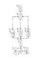
図3は、Bモード画像、ドップラスペクトルおよびカラードップラ画像による、従来の超音波診断画像装置の図を示す。装置は、たとえば弾性画像、3D画像、リアルタイム3D画像、組織ドップラ画像、組織ハーモニック画像、コントラスト画像などの、その他の画像モードを有していてもよい。超音波信号は、送受信スイッチ320を介して送信機/送信ビームフォーマ310によって駆動された超音波プローブ330から送信される。プローブ330は、送信超音波ビームが集束および偏向されるように、送信機/送信ビームフォーマ310によって、異なる時間遅延で別々に駆動される超音波振動子素子のアレイからなっていてもよい。受信ビームフォーマ340は、スイッチ320を介してプローブ330からの受信超音波信号を受信し、信号325を処理する。受信ビームフォーマ340は、遅延および/または位相を信号に加え、得られた信号は、受信した超音波ビームの集束および偏向のために加算される。受信ビームフォーマ340は、アポダイゼーション、増幅およびフィルタリングを適用してもよい。
FIG. 3 shows a diagram of a conventional ultrasound diagnostic imaging device with B-mode images, Doppler spectra and color Doppler images. The device may have other image modes, such as elastic images, 3D images, real-time 3D images, tissue Doppler images, tissue harmonic images, contrast images, and the like. The ultrasonic signal is transmitted from the
処理された信号345は、ドップラスペクトルプロセッサ350、カラードップラプロセッサ360、およびBモード画像プロセッサ370に結合される。ドップラスペクトルプロセッサ350は、ドップラ信号プロセッサおよびスペクトル解析器を備え、ドップラフロー速度信号を処理し、ドップラスペクトル355を算出および出力する。カラードップラプロセッサ360は、受信した信号345を処理し、速度、パワーおよび分散信号365を算出および出力する。Bモード画像プロセッサ370は、受信した信号345を処理し、振幅検出により、Bモード画像375または信号の振幅を算出および出力する。
The processed
ドップラスペクトル信号355、カラードップラプロセッサ信号(速度、パワー、および分散)365およびBモードプロセッサ信号375は、信号をスキャン変換信号に変換するスキャンコンバータ380に結合される。スキャンコンバータ380の出力は、超音波画像を表示するためのディスプレイモニタ390に結合される。
Doppler
図2は、いくつかの実施形態による、せん断波プロセッサ295を備える超音波画像装置の要素の図を示す。図2の超音波装置は、強い超音波パルスを生体組織に送信して、生体組織を押す音響放射力を生み出す。生体組織が押された後、せん断波が生成され、組織内を伝搬する。次いで、せん断波が生体組織内を伝搬する際に、せん断波をトラッキングするために、超音波装置は、超音波パルスを送受信する。受信ビームフォーマ240は、複数の受信超音波ビームを同時に形成する事ができる。同様に、送信機/送信ビームフォーマ210は、複数の送信超音波ビームを同時に形成する事ができる。受信ビームフォーマ240から受信した超音波信号は処理されて、上記のように、組織の変位、ドップラ速度、相関、せん断波の伝搬速度および/またはせん断波の伝搬速度の2乗が得られる。せん断波プロセッサ295は、上記のせん断波処理方法を実施することができる。せん断波プロセッサ295は、受信ビームフォーマ240からの出力245を受信する。出力297は、せん断波速度データまたは他のせん断波特性を含む。たとえば、せん断波プロセッサ295は、伝搬速度またはせん断波の伝搬速度の2乗を、スキャンコンバータ280に出力し、せん断波の伝搬速度またはせん断波の伝搬速度の2乗を表現するものが、Bモード画像、カラードップラ画像またはスペクトルドップラ画像とともにディスプレイモニタに出力される。
FIG. 2 shows a diagram of elements of an ultrasound imaging device comprising a
せん断波プロセッサ295は、汎用の中央処理装置(CPU)、デジタル信号プロセッサ(DSP)、フィールドプログラマブルゲートアレイ(FPGA)、グラフィック処理ユニット(GPU)および/または個別の電子デバイスを備えていてもよい。
The
図2は、いくつかの実施形態による論理構造を表しており、実際の実装は、別のやり方で構成したより多くのまた異なる要素を含み得る。他のトポロジを他の実施形態とともに使用してもよい。さらに、図2の装置の各要素は、任意の数の演算デバイスによって、任意の数の他の公衆および/または私的ネットワークを介して互いに通信して実装されてもよい。そのような演算デバイスの2つ以上が、互いに離れたところに位置していてもよく、(1つ以上の)ネットワークおよび/または専用の接続のうちの任意の知られている方法によって互いに通信してもよい。装置は、本明細書に記載の機能とともに任意の他の機能を提供するのに適切な、任意の数のハードウェアおよび/またはソフトウェア要素を含み得る。たとえば、図2の装置の実装において使用される任意の演算デバイスは、演算デバイスが、本明細書に記載するように動作するようにプログラムコードを実行するためのプロセッサを含み得る。 FIG. 2 represents a logical structure according to some embodiments, and an actual implementation may include more and different elements configured differently. Other topologies may be used with other embodiments. Further, each element of the apparatus of FIG. 2 may be implemented by any number of computing devices in communication with each other via any number of other public and / or private networks. Two or more of such computing devices may be located remotely from each other and communicate with each other by any known method of (one or more) networks and / or dedicated connections. May be. An apparatus may include any number of hardware and / or software elements suitable to provide any other functionality in conjunction with the functionality described herein. For example, any computing device used in the implementation of the apparatus of FIG. 2 may include a processor for executing program code such that the computing device operates as described herein.
本明細書で論じたすべての装置および処理は、1つ以上の一時的でないコンピュータ可読媒体に格納されたプログラムコードにおいて実現され得る。そのような媒体には、たとえば、フロッピー(登録商標)ディスク、CD−ROM、DVD−ROM、Blu−rayディスク、フラッシュドライブ、磁気テープ、およびソリッドステートのランダムアクセスメモリ(RAM)または読取り専用メモリ(ROM)などのストレージユニットが含まれ得る。したがって、各実施形態は、ハードウェアおよびソフトウェアの任意の特定の組合せには限定されない。 All devices and processes discussed herein may be implemented in program code stored on one or more non-transitory computer readable media. Such media include, for example, floppy disks, CD-ROMs, DVD-ROMs, Blu-ray disks, flash drives, magnetic tapes, and solid state random access memory (RAM) or read-only memory ( A storage unit such as a ROM). Thus, each embodiment is not limited to any specific combination of hardware and software.
1つ以上の実施形態を説明してきた。しかしながら、さまざまな変形が当業者には明白であろう。 One or more embodiments have been described. However, various modifications will be apparent to those skilled in the art.
Claims (48)
集束した超音波パルスを前記生体組織内に送信するステップと、
前記集束した超音波パルスに応答して生成される、前記生体組織からの1つ以上の超音波信号を受信するステップと、
前記受信した1つ以上の超音波信号に基づいて、前記生体組織内の前記せん断波を検出するステップと、
前記検出したせん断波に関連付けられた少なくとも1つの伝搬特性を判定するステップと、
コード化方法を使用して、前記検出したせん断波に関連付けられた前記少なくとも1つの伝搬特性を表示するステップと
を含むことを特徴とする方法。 Irradiating a biological tissue with a first ultrasonic pulse to generate a shear wave in the biological tissue;
Transmitting focused ultrasound pulses into the living tissue;
Receiving one or more ultrasound signals from the biological tissue generated in response to the focused ultrasound pulse;
Detecting the shear wave in the biological tissue based on the received one or more ultrasound signals;
Determining at least one propagation characteristic associated with the detected shear wave;
Displaying the at least one propagation characteristic associated with the detected shear wave using an encoding method.
前記検出したせん断波のうちの1つ以上に関連付けられた伝搬速度、および
実数(b)と前記せん断波の伝搬速度の2乗(c2)の積(bc2)
のうちの1つ以上を含むことを特徴とする方法。 The method of claim 1, wherein the propagation characteristics of the at least one shear wave are:
The propagation velocity associated with one or more of the detected shear waves, and the product of the real number (b) and the square of the propagation velocity of the shear wave (c 2 ) (bc 2 )
A method comprising one or more of:
前記複数の超音波パルスのそれぞれが、異なる焦点に集束することを特徴とする方法。 2. The method according to claim 1, wherein the step of irradiating the first ultrasonic pulse includes the step of irradiating the biological tissue with a plurality of ultrasonic pulses to generate a shear wave in the biological tissue. Including
Each of the plurality of ultrasonic pulses is focused at a different focal point.
前記1つ以上の超音波信号が、1つ以上の時点において前記生体組織から受信されることを特徴とする方法。 2. The method of claim 1, wherein transmitting the focused ultrasound pulse comprises transmitting a plurality of focused ultrasound pulses into the living tissue more than once.
The method wherein the one or more ultrasound signals are received from the living tissue at one or more time points.
第1の超音波パルスを生体組織に照射して、前記生体組織内にせん断波を生成させること、
集束した超音波パルスを前記生体組織内に送信すること、
前記集束した超音波パルスに応答して生成される、前記生体組織からの1つ以上の超音波信号を受信すること、
前記受信した1つ以上の超音波信号に基づいて、前記生体組織内の前記せん断波を検出すること、
前記検出したせん断波に関連付けられた少なくとも1つの伝搬特性を判定すること、および
コード化媒体を使用して、前記検出したせん断波に関連付けられた前記少なくとも1つの伝搬特性を表示すること
を行うように、前記プログラムコードがデバイスによって実行可能であることを特徴とする媒体。 A non-transitory medium storing program code executable by a processor,
Irradiating a living tissue with a first ultrasonic pulse to generate a shear wave in the living tissue;
Transmitting focused ultrasound pulses into the living tissue;
Receiving one or more ultrasound signals from the biological tissue generated in response to the focused ultrasound pulse;
Detecting the shear wave in the biological tissue based on the received one or more ultrasound signals;
Determining at least one propagation characteristic associated with the detected shear wave, and using a coded medium to display the at least one propagation characteristic associated with the detected shear wave. And the program code is executable by a device.
前記検出したせん断波のうちの1つ以上に関連付けられた伝搬速度、および
実数(b)と前記せん断波の伝搬速度の2乗(c2)の積(bc2)
のうちの1つ以上を含むことを特徴とする媒体。 18. The medium of claim 17, wherein the propagation characteristics of the at least one shear wave are
The propagation velocity associated with one or more of the detected shear waves, and the product of the real number (b) and the square of the propagation velocity of the shear wave (c 2 ) (bc 2 )
A medium comprising one or more of the following:
前記複数の超音波パルスのそれぞれが、異なる焦点に集束することを特徴とする媒体。 18. The medium according to claim 17, wherein irradiating the first ultrasonic pulse includes irradiating the biological tissue with a plurality of ultrasonic pulses to generate shear waves in the biological tissue. Including
Each of the plurality of ultrasonic pulses is focused on a different focal point.
前記1つ以上の超音波信号が、1つ以上の時点において前記生体組織から受信されることを特徴とする媒体。 18. The medium of claim 17, wherein transmitting the focused ultrasound pulse comprises transmitting a plurality of focused ultrasound pulses into the living tissue more than once.
The medium, wherein the one or more ultrasound signals are received from the living tissue at one or more time points.
プロセッサが実行可能なプログラムコードを記憶したメモリと、
第1の超音波パルスを生体組織に照射して、前記生体組織内にせん断波を生成させること、
集束した超音波パルスを前記生体組織内に送信すること、
前記集束した超音波パルスに応答して生成される、前記生体組織からの1つ以上の超音波信号を受信すること、
前記受信した1つ以上の超音波信号に基づいて、前記生体組織内の前記せん断波を検出すること、
前記検出したせん断波に関連付けられた少なくとも1つの伝搬特性を判定すること、および
コード化装置を使用して、前記検出したせん断波に関連付けられた前記少なくとも1つの伝搬特性を表示すること
を前記装置に実施させるために、プロセッサが実行可能な前記プログラムコードを実行するためのプロセッサと
を備えることを特徴とする装置。 A device,
A memory storing program code executable by the processor;
Irradiating a living tissue with a first ultrasonic pulse to generate a shear wave in the living tissue;
Transmitting focused ultrasound pulses into the living tissue;
Receiving one or more ultrasound signals from the biological tissue generated in response to the focused ultrasound pulse;
Detecting the shear wave in the biological tissue based on the received one or more ultrasound signals;
Determining at least one propagation characteristic associated with the detected shear wave; and using an encoding device to display the at least one propagation characteristic associated with the detected shear wave. And a processor for executing the program code executable by the processor.
前記検出したせん断波のうちの1つ以上に関連付けられた伝搬速度、および
実数(b)と前記せん断波の伝搬速度の2乗(c2)の積(bc2)
のうちの1つ以上を含むことを特徴とする装置。 34. The apparatus of claim 33, wherein the propagation characteristics of the at least one shear wave are:
The propagation velocity associated with one or more of the detected shear waves, and the product of the real number (b) and the square of the propagation velocity of the shear wave (c 2 ) (bc 2 )
An apparatus comprising one or more of:
第1の集束した超音波パルスを送信した後であり、前記第1の集束した超音波パルスが超音波領域の最深部から振動子に戻ってくる前に、第2の集束した超音波パルスを前記振動子から送信すること
を前記装置に実施させるために、プロセッサが実行可能な前記プログラムコードをさらに実行することを特徴とする装置。 34. The apparatus of claim 33, wherein the processor is
After transmitting the first focused ultrasound pulse, before the first focused ultrasound pulse returns from the deepest part of the ultrasound region to the transducer, the second focused ultrasound pulse is An apparatus further executing the program code executable by a processor to cause the apparatus to perform transmission from the transducer.
前記複数の超音波パルスのそれぞれが、異なる焦点に集束することを特徴とする装置。 34. The apparatus according to claim 33, wherein irradiating the first ultrasonic pulse includes irradiating the biological tissue with a plurality of ultrasonic pulses to generate shear waves in the biological tissue. Including
The apparatus characterized in that each of the plurality of ultrasonic pulses is focused at a different focal point.
前記1つ以上の超音波信号が、1つ以上の時点において前記生体組織から受信されることを特徴とする装置。 34. The apparatus of claim 33, wherein transmitting the focused ultrasound pulse comprises transmitting a plurality of focused ultrasound pulses into the living tissue more than once.
The apparatus wherein the one or more ultrasound signals are received from the living tissue at one or more time points.
Applications Claiming Priority (9)
| Application Number | Priority Date | Filing Date | Title |
|---|---|---|---|
| US32100510P | 2010-04-05 | 2010-04-05 | |
| US61/321,005 | 2010-04-05 | ||
| US32134110P | 2010-04-06 | 2010-04-06 | |
| US61/321,341 | 2010-04-06 | ||
| US35058510P | 2010-06-02 | 2010-06-02 | |
| US61/350,585 | 2010-06-02 | ||
| US13/030,718 US8715185B2 (en) | 2010-04-05 | 2011-02-18 | Methods and apparatus for ultrasound imaging |
| US13/030,718 | 2011-02-18 | ||
| PCT/US2011/029402 WO2011126729A2 (en) | 2010-04-05 | 2011-03-22 | Methods and apparatus for ultrasound imaging |
Publications (2)
| Publication Number | Publication Date |
|---|---|
| JP2013523325A true JP2013523325A (en) | 2013-06-17 |
| JP2013523325A5 JP2013523325A5 (en) | 2014-05-08 |
Family
ID=44710464
Family Applications (3)
| Application Number | Title | Priority Date | Filing Date |
|---|---|---|---|
| JP2013503768A Pending JP2013523325A (en) | 2010-04-05 | 2011-03-22 | Ultrasound imaging method and apparatus |
| JP2013503766A Pending JP2013523323A (en) | 2010-04-05 | 2011-03-22 | Ultrasound imaging method and apparatus |
| JP2013503767A Pending JP2013523324A (en) | 2010-04-05 | 2011-03-22 | Ultrasound imaging method and apparatus |
Family Applications After (2)
| Application Number | Title | Priority Date | Filing Date |
|---|---|---|---|
| JP2013503766A Pending JP2013523323A (en) | 2010-04-05 | 2011-03-22 | Ultrasound imaging method and apparatus |
| JP2013503767A Pending JP2013523324A (en) | 2010-04-05 | 2011-03-22 | Ultrasound imaging method and apparatus |
Country Status (5)
| Country | Link |
|---|---|
| US (3) | US8715185B2 (en) |
| EP (3) | EP2555685A4 (en) |
| JP (3) | JP2013523325A (en) |
| CN (3) | CN103096812B (en) |
| WO (3) | WO2011126727A2 (en) |
Cited By (3)
| Publication number | Priority date | Publication date | Assignee | Title |
|---|---|---|---|---|
| JP2015128554A (en) * | 2014-01-09 | 2015-07-16 | 日立アロカメディカル株式会社 | Ultrasonic diagnostic equipment |
| JP2015131097A (en) * | 2013-12-13 | 2015-07-23 | 株式会社東芝 | Ultrasonic diagnostic apparatus, image processing apparatus and image processing method |
| JP2016047474A (en) * | 2016-01-08 | 2016-04-07 | ジーイー・メディカル・システムズ・グローバル・テクノロジー・カンパニー・エルエルシー | Ultrasonic diagnostic device |
Families Citing this family (35)
| Publication number | Priority date | Publication date | Assignee | Title |
|---|---|---|---|---|
| US8715185B2 (en) * | 2010-04-05 | 2014-05-06 | Hitachi Aloka Medical, Ltd. | Methods and apparatus for ultrasound imaging |
| WO2011153268A2 (en) * | 2010-06-01 | 2011-12-08 | The Trustees Of Columbia University In The City Of New York | Devices, methods, and systems for measuring elastic properties of biological tissues |
| EP2589342A1 (en) * | 2010-06-30 | 2013-05-08 | FUJIFILM Corporation | Ultrasound diagnosis device and ultrasound diagnosis method |
| EP2589341A1 (en) | 2010-06-30 | 2013-05-08 | FUJIFILM Corporation | Ultrasound diagnostic device and ultrasound diagnostic method |
| WO2012116364A1 (en) * | 2011-02-25 | 2012-08-30 | Mayo Foundation For Medical Education And Research | Ultrasound vibrometry with unfocused ultrasound |
| US20120253194A1 (en) * | 2011-03-30 | 2012-10-04 | Tadashi Tamura | Methods and apparatus for ultrasound imaging |
| US10338203B2 (en) * | 2011-09-09 | 2019-07-02 | Siemens Medical Solutions Usa, Inc. | Classification preprocessing in medical ultrasound shear wave imaging |
| US8801614B2 (en) * | 2012-02-10 | 2014-08-12 | Siemens Medical Solutions Usa, Inc. | On-axis shear wave characterization with ultrasound |
| JP6438769B2 (en) | 2012-02-21 | 2018-12-19 | マウイ イマギング,インコーポレーテッド | Determination of material hardness using multiple aperture ultrasound. |
| US9220479B2 (en) * | 2012-03-30 | 2015-12-29 | Hitachi Aloka Medical, Ltd. | Methods and apparatus for ultrasound imaging |
| US8951198B2 (en) * | 2012-03-30 | 2015-02-10 | Hitachi Aloka Medical, Ltd. | Methods and apparatus for ultrasound imaging |
| US9211111B2 (en) * | 2012-04-05 | 2015-12-15 | Hitachi Aloka Medical, Ltd. | Determination of shear wave characteristics |
| JP5771758B2 (en) * | 2012-12-25 | 2015-09-02 | 日立アロカメディカル株式会社 | Ultrasonic diagnostic equipment |
| CN105188556B (en) * | 2013-02-25 | 2017-11-07 | 皇家飞利浦有限公司 | Determination to the concentration distribution of acoustics dispersed elements |
| US9332962B2 (en) * | 2013-03-13 | 2016-05-10 | Siemens Medical Solutions Usa, Inc. | Ultrasound ARFI displacement imaging using an adaptive time instance |
| CN107296629A (en) | 2013-03-28 | 2017-10-27 | 佳能株式会社 | Diagnostic ultrasound equipment and ultrasonic diagnosis method |
| US20160192906A1 (en) * | 2013-08-12 | 2016-07-07 | Samsung Electronics Co., Ltd. | Method for producing elastic image and ultrasonic diagnostic apparatus |
| CN103462643B (en) * | 2013-09-29 | 2015-02-11 | 深圳市开立科技有限公司 | Shear wave speed measurement method, device and system |
| KR102191967B1 (en) * | 2013-10-07 | 2020-12-16 | 삼성전자주식회사 | Apparatus and method for obtaining elastic feature of object |
| KR20150051106A (en) * | 2013-10-30 | 2015-05-11 | 아크조노벨코팅스인터내셔널비.브이. | Powder coating composition |
| KR101580584B1 (en) * | 2013-11-28 | 2015-12-28 | 삼성전자주식회사 | Method and ultrasound apparatus for marking tumor on ultrasound elastography |
| JP5952254B2 (en) * | 2013-12-24 | 2016-07-13 | ジーイー・メディカル・システムズ・グローバル・テクノロジー・カンパニー・エルエルシー | Ultrasonic diagnostic equipment |
| CN110507360B (en) * | 2014-08-28 | 2022-06-03 | 深圳迈瑞生物医疗电子股份有限公司 | Shear wave imaging method and system |
| US10863968B2 (en) * | 2014-09-30 | 2020-12-15 | Wisconsin Alumni Research Foundation | Ultrasonic imaging system with angularly compounded acoustic radiation force excitation |
| US20160143625A1 (en) * | 2014-11-26 | 2016-05-26 | Kabushiki Kaisha Toshiba | Ultrasonic probe and ultrasonic diagnosis apparatus |
| JP6307460B2 (en) * | 2015-02-27 | 2018-04-04 | ジーイー・メディカル・システムズ・グローバル・テクノロジー・カンパニー・エルエルシー | Ultrasonic diagnostic apparatus and control program therefor |
| KR20180013956A (en) * | 2015-06-01 | 2018-02-07 | 듀크 유니버시티 | Method, system and computer program product for single tracking position shear wave elastic imaging |
| US10582911B2 (en) * | 2015-08-11 | 2020-03-10 | Siemens Medical Solutions Usa, Inc. | Adaptive motion estimation in acoustic radiation force imaging |
| CN106691501A (en) * | 2015-11-12 | 2017-05-24 | 朗昇科技(苏州)有限公司 | Ultrasonic remote medical system based on Android system |
| JP7231541B2 (en) * | 2016-11-14 | 2023-03-01 | コーニンクレッカ フィリップス エヌ ヴェ | Triple-mode ultrasound imaging for anatomical, functional and hemodynamic imaging |
| US11398023B2 (en) * | 2017-05-04 | 2022-07-26 | Koninklijke Philips N.V. | System and method for concurrent visualization and quantification of wall shear stress in blood vessels |
| JP6782747B2 (en) * | 2018-10-24 | 2020-11-11 | ゼネラル・エレクトリック・カンパニイ | Ultrasonic device and its control program |
| CN110927729B (en) * | 2019-11-09 | 2022-04-01 | 天津大学 | Acoustic radiation force pulse elastography method based on displacement attenuation characteristics |
| CN111388010B (en) * | 2020-03-26 | 2022-06-24 | 深圳开立生物医疗科技股份有限公司 | Ultrasonic Doppler blood flow imaging method, device, equipment and readable storage medium |
| CN111449681B (en) * | 2020-04-08 | 2023-09-08 | 深圳开立生物医疗科技股份有限公司 | Shear wave imaging method, device, equipment and readable storage medium |
Citations (5)
| Publication number | Priority date | Publication date | Assignee | Title |
|---|---|---|---|---|
| JP2002538911A (en) * | 1999-03-15 | 2002-11-19 | ソシエテ・デラストグラフィ・アンピュルショネル・プール・レ・システム・ドゥ・メジュール・ドゥ・レラスティシテ(エスウイエスエムウ) | Imaging method and apparatus using shear wave |
| JP2002539877A (en) * | 1999-03-31 | 2002-11-26 | アキューソン コーポレイション | Ultrasound imaging system for medical diagnosis using coded transmission pulse |
| JP2009531101A (en) * | 2006-03-29 | 2009-09-03 | スーパー ソニック イマジン | Method and apparatus for imaging a viscoelastic medium |
| JP2009539528A (en) * | 2006-06-15 | 2009-11-19 | エコセンス ソシエテ アノニム | Method for measuring viscoelastic properties of biological tissue using an ultrasonic transducer |
| JP2010069295A (en) * | 2008-09-18 | 2010-04-02 | General Electric Co <Ge> | System and method for detecting region where rigidity changed |
Family Cites Families (37)
| Publication number | Priority date | Publication date | Assignee | Title |
|---|---|---|---|---|
| US4694434A (en) * | 1984-06-12 | 1987-09-15 | Von Ramm Olaf T | Three-dimensional imaging system |
| JP3187148B2 (en) * | 1991-08-26 | 2001-07-11 | 株式会社東芝 | Ultrasound diagnostic equipment |
| US5546807A (en) * | 1994-12-02 | 1996-08-20 | Oxaal; John T. | High speed volumetric ultrasound imaging system |
| US5606971A (en) | 1995-11-13 | 1997-03-04 | Artann Corporation, A Nj Corp. | Method and device for shear wave elasticity imaging |
| US5810731A (en) | 1995-11-13 | 1998-09-22 | Artann Laboratories | Method and apparatus for elasticity imaging using remotely induced shear wave |
| US6086539A (en) * | 1996-12-04 | 2000-07-11 | Acuson Corporation | Methods and apparatus for ultrasound image quantification |
| US6010456A (en) * | 1998-12-30 | 2000-01-04 | General Electric Company | Method and apparatus for acoustic subtraction imaging using linear and nonlinear ultrasonic images |
| JP2001212144A (en) | 2000-01-31 | 2001-08-07 | Toshiba Corp | Ultrasonic diagnostic apparatus and ultrasonic imaging method |
| EP1278459A1 (en) * | 2000-04-26 | 2003-01-29 | Koninklijke Philips Electronics N.V. | Ultrasonic method and system for shear wave parameter estimation |
| US20060079773A1 (en) * | 2000-11-28 | 2006-04-13 | Allez Physionix Limited | Systems and methods for making non-invasive physiological assessments by detecting induced acoustic emissions |
| US7022077B2 (en) | 2000-11-28 | 2006-04-04 | Allez Physionix Ltd. | Systems and methods for making noninvasive assessments of cardiac tissue and parameters |
| JP2002315749A (en) | 2001-04-24 | 2002-10-29 | Olympus Optical Co Ltd | Ultrasonic drive circuit |
| US6592522B2 (en) | 2001-06-12 | 2003-07-15 | Ge Medical Systems Global Technology Company, Llc | Ultrasound display of displacement |
| FR2844058B1 (en) | 2002-09-02 | 2004-11-12 | Centre Nat Rech Scient | IMAGING METHOD AND DEVICE USING SHEAR WAVES |
| US6764448B2 (en) * | 2002-10-07 | 2004-07-20 | Duke University | Methods, systems, and computer program products for imaging using virtual extended shear wave sources |
| US7901355B2 (en) * | 2003-01-23 | 2011-03-08 | L'oreal | Skin analysis apparatus including an ultrasound probe |
| US7344509B2 (en) | 2003-04-17 | 2008-03-18 | Kullervo Hynynen | Shear mode therapeutic ultrasound |
| US7175599B2 (en) | 2003-04-17 | 2007-02-13 | Brigham And Women's Hospital, Inc. | Shear mode diagnostic ultrasound |
| CN100562293C (en) | 2003-04-17 | 2009-11-25 | 布赖汉姆妇女医院 | The shear mode therapeutic ultrasound system |
| EP1633234A4 (en) | 2003-06-03 | 2009-05-13 | Physiosonics Inc | Systems and methods for determining intracranial pressure non-invasively and acoustic transducer assemblies for use in such systems |
| US7785259B2 (en) | 2003-10-03 | 2010-08-31 | Mayo Foundation For Medical Education And Research | Detection of motion in vibro-acoustography |
| JP2007014684A (en) * | 2005-07-11 | 2007-01-25 | Motoharu Hasegawa | Arteriosclerosis evaluation apparatus and arteriosclerosis index calculation program |
| GB2428477A (en) | 2005-07-20 | 2007-01-31 | David Richard Andrews | Inspection device for heterogeneous structures |
| EP2048511B1 (en) * | 2006-03-31 | 2014-02-26 | Hitachi Aloka Medical, Ltd. | Methods and apparatus for 3D ultrasound imaging with automatic gain compensation |
| US8118744B2 (en) * | 2007-02-09 | 2012-02-21 | Duke University | Methods, systems and computer program products for ultrasound shear wave velocity estimation and shear modulus reconstruction |
| FR2913875B1 (en) | 2007-03-21 | 2009-08-07 | Echosens Sa | DEVICE FOR MEASURING VISCOELASTIC PROPERTIES OF BIOLOGICAL TISSUES AND METHOD USING THE DEVICE |
| WO2008141220A1 (en) | 2007-05-09 | 2008-11-20 | University Of Rochester | Shear modulus estimation by application of spatially modulated impulse acoustic radiation force approximation |
| US8187187B2 (en) | 2008-07-16 | 2012-05-29 | Siemens Medical Solutions Usa, Inc. | Shear wave imaging |
| US20100286520A1 (en) * | 2009-05-11 | 2010-11-11 | General Electric Company | Ultrasound system and method to determine mechanical properties of a target region |
| CN102469989B (en) * | 2009-07-07 | 2014-04-16 | 株式会社日立医疗器械 | Ultrasonic diagnosis apparatus and ultrasonic measurement method |
| US8715185B2 (en) * | 2010-04-05 | 2014-05-06 | Hitachi Aloka Medical, Ltd. | Methods and apparatus for ultrasound imaging |
| US8961418B2 (en) * | 2010-10-06 | 2015-02-24 | Siemens Medical Solutions Usa, Inc. | Solving for shear wave information in medical ultrasound imaging |
| US8469891B2 (en) * | 2011-02-17 | 2013-06-25 | Siemens Medical Solutions Usa, Inc. | Viscoelasticity measurement using amplitude-phase modulated ultrasound wave |
| US20120253194A1 (en) * | 2011-03-30 | 2012-10-04 | Tadashi Tamura | Methods and apparatus for ultrasound imaging |
| US8951198B2 (en) * | 2012-03-30 | 2015-02-10 | Hitachi Aloka Medical, Ltd. | Methods and apparatus for ultrasound imaging |
| US9220479B2 (en) * | 2012-03-30 | 2015-12-29 | Hitachi Aloka Medical, Ltd. | Methods and apparatus for ultrasound imaging |
| US9211111B2 (en) * | 2012-04-05 | 2015-12-15 | Hitachi Aloka Medical, Ltd. | Determination of shear wave characteristics |
-
2011
- 2011-02-18 US US13/030,718 patent/US8715185B2/en not_active Expired - Fee Related
- 2011-02-18 US US13/030,891 patent/US20110245668A1/en not_active Abandoned
- 2011-02-18 US US13/030,831 patent/US9351707B2/en not_active Expired - Fee Related
- 2011-03-22 WO PCT/US2011/029389 patent/WO2011126727A2/en active Application Filing
- 2011-03-22 WO PCT/US2011/029402 patent/WO2011126729A2/en active Application Filing
- 2011-03-22 JP JP2013503768A patent/JP2013523325A/en active Pending
- 2011-03-22 JP JP2013503766A patent/JP2013523323A/en active Pending
- 2011-03-22 CN CN201180017546.2A patent/CN103096812B/en not_active Expired - Fee Related
- 2011-03-22 EP EP11766381.5A patent/EP2555685A4/en not_active Withdrawn
- 2011-03-22 EP EP11766382.3A patent/EP2555686A4/en not_active Withdrawn
- 2011-03-22 CN CN201180017483.0A patent/CN102821700B/en not_active Expired - Fee Related
- 2011-03-22 WO PCT/US2011/029396 patent/WO2011126728A2/en active Application Filing
- 2011-03-22 CN CN201180017478.XA patent/CN102892358B/en not_active Expired - Fee Related
- 2011-03-22 EP EP11766380.7A patent/EP2555684A4/en not_active Withdrawn
- 2011-03-22 JP JP2013503767A patent/JP2013523324A/en active Pending
Patent Citations (5)
| Publication number | Priority date | Publication date | Assignee | Title |
|---|---|---|---|---|
| JP2002538911A (en) * | 1999-03-15 | 2002-11-19 | ソシエテ・デラストグラフィ・アンピュルショネル・プール・レ・システム・ドゥ・メジュール・ドゥ・レラスティシテ(エスウイエスエムウ) | Imaging method and apparatus using shear wave |
| JP2002539877A (en) * | 1999-03-31 | 2002-11-26 | アキューソン コーポレイション | Ultrasound imaging system for medical diagnosis using coded transmission pulse |
| JP2009531101A (en) * | 2006-03-29 | 2009-09-03 | スーパー ソニック イマジン | Method and apparatus for imaging a viscoelastic medium |
| JP2009539528A (en) * | 2006-06-15 | 2009-11-19 | エコセンス ソシエテ アノニム | Method for measuring viscoelastic properties of biological tissue using an ultrasonic transducer |
| JP2010069295A (en) * | 2008-09-18 | 2010-04-02 | General Electric Co <Ge> | System and method for detecting region where rigidity changed |
Cited By (4)
| Publication number | Priority date | Publication date | Assignee | Title |
|---|---|---|---|---|
| JP2015131097A (en) * | 2013-12-13 | 2015-07-23 | 株式会社東芝 | Ultrasonic diagnostic apparatus, image processing apparatus and image processing method |
| US11534142B2 (en) | 2013-12-13 | 2022-12-27 | Canon Medical Systems Corporation | Ultrasonic diagnosis apparatus, image processing apparatus, and image processing method for tissue displacement caused by a shearwave generated by acoustic radiation force |
| JP2015128554A (en) * | 2014-01-09 | 2015-07-16 | 日立アロカメディカル株式会社 | Ultrasonic diagnostic equipment |
| JP2016047474A (en) * | 2016-01-08 | 2016-04-07 | ジーイー・メディカル・システムズ・グローバル・テクノロジー・カンパニー・エルエルシー | Ultrasonic diagnostic device |
Also Published As
| Publication number | Publication date |
|---|---|
| CN102892358A (en) | 2013-01-23 |
| CN102821700B (en) | 2015-04-08 |
| US20110245678A1 (en) | 2011-10-06 |
| CN102821700A (en) | 2012-12-12 |
| EP2555685A4 (en) | 2014-08-20 |
| JP2013523323A (en) | 2013-06-17 |
| US20110245668A1 (en) | 2011-10-06 |
| CN103096812B (en) | 2015-12-02 |
| WO2011126729A3 (en) | 2011-12-29 |
| JP2013523324A (en) | 2013-06-17 |
| WO2011126729A2 (en) | 2011-10-13 |
| CN103096812A (en) | 2013-05-08 |
| CN102892358B (en) | 2014-11-26 |
| EP2555684A4 (en) | 2014-08-20 |
| WO2011126728A2 (en) | 2011-10-13 |
| US9351707B2 (en) | 2016-05-31 |
| EP2555686A4 (en) | 2014-08-20 |
| US8715185B2 (en) | 2014-05-06 |
| EP2555686A2 (en) | 2013-02-13 |
| EP2555684A2 (en) | 2013-02-13 |
| EP2555685A2 (en) | 2013-02-13 |
| WO2011126728A3 (en) | 2011-12-29 |
| WO2011126727A3 (en) | 2011-12-29 |
| WO2011126727A2 (en) | 2011-10-13 |
| US20110245672A1 (en) | 2011-10-06 |
Similar Documents
| Publication | Publication Date | Title |
|---|---|---|
| JP5882447B2 (en) | Ultrasonic imaging method and ultrasonic imaging apparatus | |
| US8715185B2 (en) | Methods and apparatus for ultrasound imaging | |
| JP6063553B2 (en) | Ultrasonic imaging method and ultrasonic imaging apparatus | |
| US9211111B2 (en) | Determination of shear wave characteristics | |
| Jensen | Medical ultrasound imaging | |
| JP6063552B2 (en) | Ultrasonic imaging method and ultrasonic imaging apparatus | |
| US8801614B2 (en) | On-axis shear wave characterization with ultrasound | |
| US11154277B2 (en) | Tissue viscoelastic estimation from shear velocity in ultrasound medical imaging | |
| JP2011526181A (en) | High frame rate quantitative Doppler flow imaging using unfocused transmit beams | |
| CN107049361B (en) | Sound velocity imaging using shear waves | |
| KR20150130093A (en) | Estimation method and system for shear wave speed and lesion diagnosis method and system in the tissue using the same | |
| JP2003275210A (en) | Method for describing spectrum strain and apparatus therefor |
Legal Events
| Date | Code | Title | Description |
|---|---|---|---|
| A521 | Written amendment |
Free format text: JAPANESE INTERMEDIATE CODE: A523 Effective date: 20140319 |
|
| A621 | Written request for application examination |
Free format text: JAPANESE INTERMEDIATE CODE: A621 Effective date: 20140319 |
|
| A977 | Report on retrieval |
Free format text: JAPANESE INTERMEDIATE CODE: A971007 Effective date: 20141212 |
|
| A131 | Notification of reasons for refusal |
Free format text: JAPANESE INTERMEDIATE CODE: A131 Effective date: 20141216 |
|
| A521 | Written amendment |
Free format text: JAPANESE INTERMEDIATE CODE: A523 Effective date: 20150210 |
|
| A131 | Notification of reasons for refusal |
Free format text: JAPANESE INTERMEDIATE CODE: A131 Effective date: 20150707 |
|
| A02 | Decision of refusal |
Free format text: JAPANESE INTERMEDIATE CODE: A02 Effective date: 20151110 |