JP2013235231A - Image forming device and control method - Google Patents

Image forming device and control method Download PDF

Info

Publication number
JP2013235231A
JP2013235231A JP2012208184A JP2012208184A JP2013235231A JP 2013235231 A JP2013235231 A JP 2013235231A JP 2012208184 A JP2012208184 A JP 2012208184A JP 2012208184 A JP2012208184 A JP 2012208184A JP 2013235231 A JP2013235231 A JP 2013235231A
Authority
JP
Japan
Prior art keywords
pressure
temperature
contact
fixing
roller
Prior art date
Legal status (The legal status is an assumption and is not a legal conclusion. Google has not performed a legal analysis and makes no representation as to the accuracy of the status listed.)
Pending
Application number
JP2012208184A
Other languages
Japanese (ja)
Inventor
Tsutomu Sakamaki
務 酒巻
Takashi Yamada
貴 山田
Current Assignee (The listed assignees may be inaccurate. Google has not performed a legal analysis and makes no representation or warranty as to the accuracy of the list.)
Konica Minolta Inc
Original Assignee
Konica Minolta Inc
Priority date (The priority date is an assumption and is not a legal conclusion. Google has not performed a legal analysis and makes no representation as to the accuracy of the date listed.)
Filing date
Publication date
Application filed by Konica Minolta Inc filed Critical Konica Minolta Inc
Priority to JP2012208184A priority Critical patent/JP2013235231A/en
Priority to US13/845,991 priority patent/US9002228B2/en
Priority to CN201310120070.6A priority patent/CN103823345B/en
Publication of JP2013235231A publication Critical patent/JP2013235231A/en
Pending legal-status Critical Current

Links

Images

Classifications

    • GPHYSICS
    • G03PHOTOGRAPHY; CINEMATOGRAPHY; ANALOGOUS TECHNIQUES USING WAVES OTHER THAN OPTICAL WAVES; ELECTROGRAPHY; HOLOGRAPHY
    • G03GELECTROGRAPHY; ELECTROPHOTOGRAPHY; MAGNETOGRAPHY
    • G03G15/00Apparatus for electrographic processes using a charge pattern
    • G03G15/20Apparatus for electrographic processes using a charge pattern for fixing, e.g. by using heat
    • G03G15/2003Apparatus for electrographic processes using a charge pattern for fixing, e.g. by using heat using heat
    • G03G15/2014Apparatus for electrographic processes using a charge pattern for fixing, e.g. by using heat using heat using contact heat
    • G03G15/2039Apparatus for electrographic processes using a charge pattern for fixing, e.g. by using heat using heat using contact heat with means for controlling the fixing temperature
    • G03G15/205Apparatus for electrographic processes using a charge pattern for fixing, e.g. by using heat using heat using contact heat with means for controlling the fixing temperature specially for the mode of operation, e.g. standby, warming-up, error
    • GPHYSICS
    • G03PHOTOGRAPHY; CINEMATOGRAPHY; ANALOGOUS TECHNIQUES USING WAVES OTHER THAN OPTICAL WAVES; ELECTROGRAPHY; HOLOGRAPHY
    • G03GELECTROGRAPHY; ELECTROPHOTOGRAPHY; MAGNETOGRAPHY
    • G03G15/00Apparatus for electrographic processes using a charge pattern
    • G03G15/20Apparatus for electrographic processes using a charge pattern for fixing, e.g. by using heat
    • G03G15/2003Apparatus for electrographic processes using a charge pattern for fixing, e.g. by using heat using heat
    • G03G15/2014Apparatus for electrographic processes using a charge pattern for fixing, e.g. by using heat using heat using contact heat
    • G03G15/2017Structural details of the fixing unit in general, e.g. cooling means, heat shielding means
    • G03G15/2032Retractable heating or pressure unit
    • GPHYSICS
    • G03PHOTOGRAPHY; CINEMATOGRAPHY; ANALOGOUS TECHNIQUES USING WAVES OTHER THAN OPTICAL WAVES; ELECTROGRAPHY; HOLOGRAPHY
    • G03GELECTROGRAPHY; ELECTROPHOTOGRAPHY; MAGNETOGRAPHY
    • G03G15/00Apparatus for electrographic processes using a charge pattern
    • G03G15/20Apparatus for electrographic processes using a charge pattern for fixing, e.g. by using heat
    • G03G15/2003Apparatus for electrographic processes using a charge pattern for fixing, e.g. by using heat using heat
    • G03G15/2014Apparatus for electrographic processes using a charge pattern for fixing, e.g. by using heat using heat using contact heat
    • G03G15/2064Apparatus for electrographic processes using a charge pattern for fixing, e.g. by using heat using heat using contact heat combined with pressure

Abstract

PROBLEM TO BE SOLVED: To provide an image forming device that prevents a fixing failure of a toner image and reduces deterioration in durability of a heating member, and to provide a control method thereof.SOLUTION: During warm-up of an image forming device 100, when a temperature of a pressure roller 161d is substantially below a target temperature for image formation, a fixing belt 161a and a fixing roller 161c are brought into contact with the pressure roller 161d until the temperature of the pressure roller 161d reaches near the target temperature. Specifically, the fixing belt 161a and the fixing roller 161c are brought into contact with the pressure roller 161d at a contact pressure (300 N, for example) lower than the contact pressure (1500 N, for example) for image formation. During warm-up, the fixing belt 161a and the fixing roller 161c are brought into contact with the pressure roller 161d with a load smaller than that for image formation, thereby preventing durability of the fixing belt 161a and the fixing roller 161c from being deteriorated.

Description

本発明は、画像形成装置およびその制御方法に関する。   The present invention relates to an image forming apparatus and a control method thereof.

プリンタ、複写機、ファクシミリおよびこれらの複合機等の画像形成装置には、入力された画像データに基づいて用紙上に形成されたトナー像を定着させる定着装置が設けられている。定着装置においては、トナー像が形成された用紙は加熱部材(例えば、定着ローラーおよび/または定着ベルト)と加圧部材(例えば、加圧ローラー)との間に挟持され、圧接された状態で加熱されて、トナー像が用紙上に定着される。   2. Description of the Related Art Image forming apparatuses such as printers, copiers, facsimile machines, and multi-functional machines are provided with a fixing device that fixes a toner image formed on paper based on input image data. In the fixing device, the paper on which the toner image is formed is sandwiched between a heating member (for example, a fixing roller and / or a fixing belt) and a pressure member (for example, a pressure roller), and heated in a pressure contact state. Then, the toner image is fixed on the paper.

ところで、加圧部材側にヒーターが備えられていない場合、または、ヒーターが備えられても当該ヒーターの昇温能力が低い場合、プリント開始時における加熱部材と加圧部材との間の温度差が大きくなるときがある。このとき、プリント開始前のウォーミングアップ動作として、加熱部材に加圧部材を圧接すると、加熱部材の温度が大きく低下し、定着不良が発生する可能性がある。   By the way, when the heater is not provided on the pressure member side, or when the heater has a low temperature raising capability even if the heater is provided, the temperature difference between the heating member and the pressure member at the start of printing is Sometimes it grows. At this time, if the pressure member is pressed against the heating member as a warm-up operation before the start of printing, the temperature of the heating member may be greatly reduced, and fixing failure may occur.

図15は、加熱部材および加圧部材の圧接前後において、加熱部材および加圧部材の温度変化の様子を示す。図15において、曲線L0は加熱部材の温度変化、曲線L1は加圧部材の温度変化を示す。図15に示す例では、加圧部材側にヒーターが備えられていない、つまり加圧部材の温度制御は行われていない。そのため、圧接前における加圧部材の温度は約50℃と低い。したがって、加熱部材に加圧部材を圧接した場合、加熱部材の温度は15℃以上低下し、昇温不足で定着不良が発生してしまう。   FIG. 15 shows the temperature change of the heating member and the pressure member before and after the heating member and the pressure member are pressed. In FIG. 15, a curve L0 indicates a temperature change of the heating member, and a curve L1 indicates a temperature change of the pressure member. In the example shown in FIG. 15, no heater is provided on the pressure member side, that is, temperature control of the pressure member is not performed. Therefore, the temperature of the pressure member before pressure welding is as low as about 50 ° C. Therefore, when the pressure member is pressed against the heating member, the temperature of the heating member decreases by 15 ° C. or more, and fixing failure occurs due to insufficient temperature rise.

定着装置に関する技術としては、定着装置でのウォームアップ時間を短縮することが可能な技術が提案されている(例えば、特許文献1を参照)。特許文献1に記載の技術では、接離機構によって加熱部材および加圧部材を圧接状態とし、加熱部材側の加熱手段のみを通電する。そして、加熱部材が目標温度近傍まで上昇した場合、加熱部材および加圧部材を回転駆動させる。その後、加圧部材が目標温度近傍まで上昇したとき、接離機構によって加熱部材および加圧部材を離間状態とする。このように構成することにより、加熱部材側の加熱手段のみで、加熱部材および加圧部材の温度を効率的に目標温度まで上昇させることができる。特許文献1に記載の技術を適用すれば、プリント開始時における加熱部材と加圧部材との間の温度差が小さくなり、加熱部材および加圧部材の圧接により加熱部材の温度が大きく低下しないため、定着不良の発生を防止することができる。   As a technology related to the fixing device, a technology capable of shortening the warm-up time in the fixing device has been proposed (see, for example, Patent Document 1). In the technique described in Patent Document 1, the heating member and the pressure member are brought into a pressure contact state by the contact / separation mechanism, and only the heating means on the heating member side is energized. When the heating member rises to near the target temperature, the heating member and the pressure member are driven to rotate. Thereafter, when the pressure member rises to near the target temperature, the heating member and the pressure member are separated from each other by the contact / separation mechanism. By comprising in this way, the temperature of a heating member and a pressurization member can be efficiently raised to target temperature only by the heating means by the side of a heating member. If the technique described in Patent Document 1 is applied, the temperature difference between the heating member and the pressure member at the start of printing is reduced, and the temperature of the heating member is not greatly reduced by the pressure contact between the heating member and the pressure member. The occurrence of fixing failure can be prevented.

特開2007−108965号公報JP 2007-108965 A

しかしながら、上記特許文献1に記載の技術では、プリント開始前のウォームアップ動作時において、加熱部材は加圧部材により常時圧接されるため、加熱部材に永久歪みが生じ、耐久劣化が生じやすかった。   However, in the technique described in Patent Document 1, since the heating member is always pressed by the pressure member during the warm-up operation before the start of printing, the heating member is permanently deformed and durability deterioration is likely to occur.

本発明は、トナー像の定着不良を防止するとともに、加熱部材の耐久劣化を軽減することが可能な画像形成装置およびその制御方法を提供することを目的とする。   SUMMARY OF THE INVENTION An object of the present invention is to provide an image forming apparatus and a control method therefor that can prevent fixing failure of a toner image and reduce durability deterioration of a heating member.

本発明に係る画像形成装置は、
記録用紙を加熱する加熱部材と、
前記加熱部材との間で前記記録用紙を加圧する加圧部材と、
前記加熱部材と前記加圧部材との接触または離間を行う調整機構と、
ウォームアップ動作時またはアイドリング動作時に、画像形成時における前記加熱部材と前記加圧部材との間の接触圧力よりも低い接触圧力で前記加熱部材と前記加圧部材とを接触させるように前記調整機構を制御する制御部と、
を備える。
An image forming apparatus according to the present invention includes:
A heating member for heating the recording paper;
A pressure member that pressurizes the recording paper with the heating member;
An adjustment mechanism for making contact or separation between the heating member and the pressure member;
The adjusting mechanism is configured to bring the heating member and the pressure member into contact with each other at a contact pressure lower than a contact pressure between the heating member and the pressure member during image formation during a warm-up operation or an idling operation. A control unit for controlling
Is provided.

本発明に係る画像形成装置の制御方法は、
記録用紙を加熱する加熱部材と、
前記加熱部材との間で前記記録用紙を加圧する加圧部材と、
前記加熱部材と前記加圧部材との接触または離間を行う調整機構と、
を備える画像形成装置の制御方法であって、
前記制御部が、ウォームアップ動作時またはアイドリング動作時に、画像形成時における前記加熱部材と前記加圧部材との間の接触圧力よりも低い接触圧力で前記加熱部材と前記加圧部材とを接触させるように前記調整機構を制御する。
An image forming apparatus control method according to the present invention includes:
A heating member for heating the recording paper;
A pressure member that pressurizes the recording paper with the heating member;
An adjustment mechanism for making contact or separation between the heating member and the pressure member;
An image forming apparatus control method comprising:
The controller brings the heating member and the pressure member into contact with each other at a contact pressure lower than the contact pressure between the heating member and the pressure member during image formation during a warm-up operation or an idling operation. The adjustment mechanism is controlled as follows.

本発明によれば、トナー像の定着不良を防止するとともに、加熱部材の耐久劣化を軽減することが可能な画像形成装置およびその制御方法を提供することができる。   According to the present invention, it is possible to provide an image forming apparatus and a control method therefor that can prevent fixing failure of a toner image and reduce durability deterioration of a heating member.

本発明に係る第1の実施の形態を示す画像形成装置の縦断面図である。1 is a longitudinal sectional view of an image forming apparatus showing a first embodiment according to the present invention. 本発明に係る第1の実施の形態を示す画像形成装置の制御ブロック図である。1 is a control block diagram of an image forming apparatus showing a first embodiment according to the present invention. 本発明に係る第1の実施の形態を示す定着ユニット付近の構成を示す図である。FIG. 3 is a diagram illustrating a configuration in the vicinity of the fixing unit according to the first embodiment of the present invention. 本発明に係る第1の実施の形態を示す定着ユニット付近の構成を示す図である。FIG. 3 is a diagram illustrating a configuration in the vicinity of the fixing unit according to the first embodiment of the present invention. 本発明に係る第1の実施の形態を示す画像形成装置の動作例を示すフローチャートである。3 is a flowchart illustrating an operation example of the image forming apparatus according to the first exemplary embodiment of the present invention. 定着ローラーの破壊耐久実験結果を示す図である。It is a figure which shows the fracture endurance experiment result of a fixing roller. 本発明に係る第1の実施の形態を示す画像形成装置の動作の変形例を示すフローチャートである。6 is a flowchart showing a modification of the operation of the image forming apparatus showing the first exemplary embodiment of the present invention. 定着ベルトおよび定着ローラーと、加圧ローラーとの接触時間の変形例を示す図である。It is a figure which shows the modification of the contact time of a fixing belt, a fixing roller, and a pressure roller. 定着ベルトおよび定着ローラーと、加圧ローラーとの接触時間の変形例を示す図である。It is a figure which shows the modification of the contact time of a fixing belt, a fixing roller, and a pressure roller. 本発明に係る第2の実施の形態を示す画像形成装置の制御ブロック図である。FIG. 5 is a control block diagram of an image forming apparatus showing a second embodiment according to the present invention. 本発明に係る第2の実施の形態を示す定着ユニット付近の構成を示す図である。FIG. 6 is a diagram illustrating a configuration in the vicinity of a fixing unit according to a second embodiment of the present invention. 本発明に係る第2の実施の形態を示す定着ユニット付近の構成を示す図である。FIG. 6 is a diagram illustrating a configuration in the vicinity of a fixing unit according to a second embodiment of the present invention. 本発明に係る第2の実施の形態を示す画像形成装置の動作例を示すフローチャートである。6 is a flowchart illustrating an operation example of the image forming apparatus according to the second exemplary embodiment of the present invention. 定着ベルトの温度変化および加圧ローラーの温度変化を示す図である。It is a figure which shows the temperature change of a fixing belt, and the temperature change of a pressure roller. 従来技術における加熱部材の温度変化および加圧部材の温度変化を示す図である。It is a figure which shows the temperature change of the heating member in the prior art, and the temperature change of a pressurization member.

(第1の実施の形態)
以下、本発明に係る第1の実施の形態を図面に基づいて詳細に説明する。図1、2に示す画像形成装置100は、電子写真プロセス技術を利用した中間転写方式のカラー画像形成装置である。すなわち、画像形成装置100は、感光体上に形成されたC(シアン)、M(マゼンタ)、Y(イエロー)、K(ブラック)の各色トナー像を中間転写体に転写(一次転写)し、中間転写体上で4色のトナー像を重ね合わせた後、用紙に転写(二次転写)することにより、画像を形成する。
(First embodiment)
Hereinafter, a first embodiment of the present invention will be described in detail with reference to the drawings. An image forming apparatus 100 shown in FIGS. 1 and 2 is an intermediate transfer type color image forming apparatus using electrophotographic process technology. That is, the image forming apparatus 100 transfers (primary transfer) each color toner image of C (cyan), M (magenta), Y (yellow), and K (black) formed on the photosensitive member to the intermediate transfer member, An image is formed by superimposing four color toner images on the intermediate transfer member and then transferring (secondary transfer) to a sheet.

また、画像形成装置100には、CMYKの4色に対応する感光体を中間転写体の走行方向に直列配置し、中間転写体に一回の手順で各色トナー像を順次転写させるタンデム方式が採用されている。   In addition, the image forming apparatus 100 employs a tandem system in which photoconductors corresponding to four colors of CMYK are arranged in series in the running direction of the intermediate transfer member, and each color toner image is sequentially transferred to the intermediate transfer member in one procedure. Has been.

図1、2に示すように、画像形成装置100は、画像読取部110、操作表示部120、画像処理部130、画像形成部140、搬送部150、定着部160および制御部200を備える。なお、温度センサー180および駆動部190の詳細については後述する。   As illustrated in FIGS. 1 and 2, the image forming apparatus 100 includes an image reading unit 110, an operation display unit 120, an image processing unit 130, an image forming unit 140, a conveyance unit 150, a fixing unit 160, and a control unit 200. Details of the temperature sensor 180 and the drive unit 190 will be described later.

制御部200は、CPU(Central Processing Unit)201、ROM(Read Only Memory)202、RAM(Random Access Memory)203等を備えている。CPU201は、ROM202から処理内容に応じたプログラムを読み出してRAM203に展開し、展開したプログラムと協働して画像形成装置100の各ブロックの動作を集中制御する。このとき、記憶部172に格納されている各種データが参照される。記憶部172は、例えば不揮発性の半導体メモリ(いわゆるフラッシュメモリ)やハードディスクドライブで構成される。   The control unit 200 includes a CPU (Central Processing Unit) 201, a ROM (Read Only Memory) 202, a RAM (Random Access Memory) 203, and the like. The CPU 201 reads a program corresponding to the processing content from the ROM 202 and develops it in the RAM 203, and centrally controls the operation of each block of the image forming apparatus 100 in cooperation with the developed program. At this time, various data stored in the storage unit 172 are referred to. The storage unit 172 includes, for example, a nonvolatile semiconductor memory (so-called flash memory) or a hard disk drive.

制御部200は、通信部171を介して、LAN(Local Area Network)、WAN(Wide Area Network)等の通信ネットワークに接続された外部の装置(例えばパーソナルコンピュータ)との間で各種データの送受信を行う。制御部200は、例えば、外部の装置から送信された画像データを受信し、この画像データ(入力画像データ)に基づいて用紙に画像を形成させる。通信部171は、例えばLANカード等の通信制御カードで構成される。   The control unit 200 transmits and receives various data to and from an external device (for example, a personal computer) connected to a communication network such as a LAN (Local Area Network) or a WAN (Wide Area Network) via the communication unit 171. Do. For example, the control unit 200 receives image data transmitted from an external device, and forms an image on a sheet based on the image data (input image data). The communication unit 171 includes a communication control card such as a LAN card, for example.

画像読取部110は、ADF(Auto Document Feeder)と称される自動原稿給紙装置111および原稿画像走査装置(スキャナー)112等を備えて構成される。   The image reading unit 110 includes an automatic document feeder 111 called an ADF (Auto Document Feeder), a document image scanning device (scanner) 112, and the like.

自動原稿給紙装置111は、原稿トレイに載置された原稿Dを搬送機構により搬送して原稿画像走査装置112へ送り出す。自動原稿給紙装置111は、原稿トレイに載置された多数枚の原稿Dの画像(両面を含む)を連続して一挙に読み取ることができる。   The automatic document feeder 111 transports the document D placed on the document tray by the transport mechanism and sends it to the document image scanning device 112. The automatic document feeder 111 can continuously read images (including both sides) of a large number of documents D placed on a document tray all at once.

原稿画像走査装置112は、自動原稿給紙装置111からコンタクトガラス上に搬送された原稿またはコンタクトガラス上に載置された原稿を光学的に走査し、原稿からの反射光をCCD(Charge Coupled Device)センサー112aの受光面上に結像させ、原稿画像を読み取る。画像読取部110は、原稿画像走査装置112による読取結果に基づいて入力画像データを生成する。この入力画像データには、画像処理部130において所定の画像処理が施される。   The document image scanning device 112 optically scans a document conveyed on the contact glass from the automatic document feeder 111 or a document placed on the contact glass, and reflects reflected light from the document to a CCD (Charge Coupled Device). ) An image is formed on the light receiving surface of the sensor 112a, and a document image is read. The image reading unit 110 generates input image data based on the reading result by the document image scanning device 112. The input image data is subjected to predetermined image processing in the image processing unit 130.

操作表示部120は、例えばタッチパネル付の液晶ディスプレイ(LCD:Liquid Crystal Display)で構成され、表示部121および操作部122として機能する。表示部121は、制御部200から入力される表示制御信号に従って、各種操作画面、画像の状態表示、各機能の動作状況等の表示を行う。操作部122は、テンキー、スタートキー等の各種操作キーを備え、ユーザーによる各種入力操作を受け付けて、操作信号を制御部200に出力する。   The operation display unit 120 is configured by, for example, a liquid crystal display (LCD) with a touch panel, and functions as the display unit 121 and the operation unit 122. The display unit 121 displays various operation screens, image status display, operation status of each function, and the like according to a display control signal input from the control unit 200. The operation unit 122 includes various operation keys such as a numeric keypad and a start key, receives various input operations by the user, and outputs an operation signal to the control unit 200.

画像処理部130は、入力画像データに対して、初期設定またはユーザー設定に応じたデジタル画像処理を行う回路等を備えている。例えば、画像処理部130は、制御部200の制御下で、階調補正データ(階調補正テーブル)に基づいて階調補正を行う。また、画像処理部130は、入力画像データに対して、階調補正の他、色補正、シェーディング補正等の各種補正処理や、圧縮処理等を施す。これらの処理が施された画像データに基づいて、画像形成部140が制御される。   The image processing unit 130 includes a circuit that performs digital image processing on input image data according to initial settings or user settings. For example, the image processing unit 130 performs tone correction based on tone correction data (tone correction table) under the control of the control unit 200. Further, the image processing unit 130 performs various correction processes such as color correction and shading correction, a compression process, and the like on the input image data in addition to the gradation correction. Based on the image data subjected to these processes, the image forming unit 140 is controlled.

画像形成部140は、入力画像データに基づいて、Y成分、M成分、C成分、K成分の各有色トナーによる画像を形成するための画像形成ユニット141Y、141M、141C、141Kおよび中間転写ユニット142等を備えている。   The image forming unit 140 forms image with each color toner of Y component, M component, C component, and K component based on the input image data, and image forming units 141Y, 141M, 141C, 141K and intermediate transfer unit 142. Etc.

Y成分、M成分、C成分、K成分用の画像形成ユニット141Y、141M、141C、141Kは、同様の構成を有する。図示および説明の便宜上、共通する構成要素は同一の符号で示し、それぞれを区別する場合には符号にY、M、CまたはKを添えて示すこととする。図1では、Y成分用の画像形成ユニット141Yの構成要素についてのみ符号が付され、その他の画像形成ユニット141M、141C、141Kの構成要素については符号が省略されている。   The image forming units 141Y, 141M, 141C, and 141K for the Y component, M component, C component, and K component have the same configuration. For convenience of illustration and description, common constituent elements are denoted by the same reference numerals, and in order to distinguish them, Y, M, C, or K is added to the reference numerals. In FIG. 1, only the components of the image forming unit 141Y for the Y component are denoted by reference numerals, and the reference numerals are omitted for the components of the other image forming units 141M, 141C, and 141K.

画像形成ユニット141の構成を画像形成ユニット141Yにより説明する。画像形成ユニット141Yは、露光装置1411、現像装置1412、感光体ドラム1413、帯電装置1414およびドラムクリーニング装置1415等を備えている。   The configuration of the image forming unit 141 will be described using the image forming unit 141Y. The image forming unit 141Y includes an exposure device 1411, a developing device 1412, a photosensitive drum 1413, a charging device 1414, a drum cleaning device 1415, and the like.

感光体ドラム1413は、例えばアルミニウム製の導電性円筒体(アルミ素管)の周面に、アンダーコート層(UCL:Under Coat Layer)、電荷発生層(CGL:Charge Generation Layer)、電荷輸送層(CTL:Charge Transport Layer)を順次積層した負帯電型の有機感光体(OPC:Organic Photo-conductor)である。   The photosensitive drum 1413 has, for example, an undercoat layer (UCL), a charge generation layer (CGL), a charge transport layer (CGL) on the peripheral surface of an aluminum conductive cylinder (aluminum tube). It is a negatively charged organic photoreceptor (OPC: Organic Photo-conductor) in which CTL (Charge Transport Layer) is sequentially laminated.

帯電装置1414は、光導電性を有する感光体ドラム1413の表面を一様に負極性に帯電させる。露光装置1411は、例えば半導体レーザーで構成され、感光体ドラム1413に対して各色成分の画像に対応するレーザー光を照射する。感光体ドラム1413の電荷発生層で正電荷が発生し、電荷輸送層の表面まで輸送されることにより、感光体ドラム1413の表面電荷(負電荷)が中和される。感光体ドラム1413の表面には、周囲との電位差により各色成分の静電潜像が形成されることとなる。   The charging device 1414 uniformly charges the surface of the photoconductive drum 1413 to a negative polarity. The exposure device 1411 is composed of, for example, a semiconductor laser, and irradiates the photosensitive drum 1413 with laser light corresponding to the image of each color component. A positive charge is generated in the charge generation layer of the photosensitive drum 1413 and is transported to the surface of the charge transport layer, whereby the surface charge (negative charge) of the photosensitive drum 1413 is neutralized. An electrostatic latent image of each color component is formed on the surface of the photosensitive drum 1413 due to a potential difference from the surroundings.

現像装置1412は、各色成分の現像剤(例えば、小粒径のトナーと磁性体とからなる二成分現像剤)を収容しており、感光体ドラム1413の表面に各色成分のトナーを付着させることにより静電潜像を可視化してトナー像を形成する。   The developing device 1412 contains a developer of each color component (for example, a two-component developer composed of a toner having a small particle diameter and a magnetic material), and causes the toner of each color component to adhere to the surface of the photosensitive drum 1413. Thus, the electrostatic latent image is visualized to form a toner image.

ドラムクリーニング装置1415は、感光体ドラム1413の表面に摺接されるドラムクリーニングブレードを有する。一次転写後に感光体ドラム1413の表面に残存する転写残トナーは、ドラムクリーニングブレードによって掻き取られ、除去される。   The drum cleaning device 1415 has a drum cleaning blade that is in sliding contact with the surface of the photosensitive drum 1413. Transfer residual toner remaining on the surface of the photosensitive drum 1413 after the primary transfer is scraped off and removed by a drum cleaning blade.

中間転写ユニット142は、中間転写体となる中間転写ベルト1421、一次転写ローラー1422、二次転写ローラー1423、駆動ローラー1424、従動ローラー1425およびベルトクリーニング装置1426等を備えている。   The intermediate transfer unit 142 includes an intermediate transfer belt 1421 serving as an intermediate transfer member, a primary transfer roller 1422, a secondary transfer roller 1423, a driving roller 1424, a driven roller 1425, a belt cleaning device 1426, and the like.

中間転写ベルト1421は無端状ベルトで構成され、駆動ローラー1424および従動ローラー1425に張架される。中間転写ベルト1421は、駆動ローラー1424の回転により矢印A方向に一定速度で走行する。一次転写ローラー1422によって、中間転写ベルト1421が感光体ドラム1413に圧接されると、中間転写ベルト1421に各色トナー像が順次重ねて一次転写される。そして、中間転写ベルト1421が二次転写ローラー1423によって用紙Sに圧接されると、中間転写ベルト1421に一次転写されたトナー像が用紙Sに二次転写される。   The intermediate transfer belt 1421 is an endless belt and is stretched around a driving roller 1424 and a driven roller 1425. Intermediate transfer belt 1421 travels at a constant speed in the direction of arrow A by the rotation of drive roller 1424. When the intermediate transfer belt 1421 is brought into pressure contact with the photosensitive drum 1413 by the primary transfer roller 1422, the respective color toner images are sequentially superimposed on the intermediate transfer belt 1421 and primarily transferred. When the intermediate transfer belt 1421 is pressed against the sheet S by the secondary transfer roller 1423, the toner image primarily transferred to the intermediate transfer belt 1421 is secondarily transferred to the sheet S.

ベルトクリーニング装置1426は、中間転写ベルト1421の表面に摺接されるベルトクリーニングブレードを有する。二次転写後に中間転写ベルト1421の表面に残存する転写残トナーは、ベルトクリーニングブレードによって掻き取られ、除去される。   The belt cleaning device 1426 has a belt cleaning blade that is in sliding contact with the surface of the intermediate transfer belt 1421. Transfer residual toner remaining on the surface of the intermediate transfer belt 1421 after the secondary transfer is scraped off and removed by a belt cleaning blade.

定着部160は、搬送されてきた用紙Sを定着ニップ部で加熱、加圧することにより、用紙Sにトナー像を定着させる。定着部160は、定着ユニット161とエア分離ユニット162とを備えて構成されるエア分離式の定着装置である。定着ユニット161は、一対の定着部材を圧接することにより形成される定着ニップ部に用紙Sを通過させて、この用紙S上に転写されたトナー画像に熱源からの熱を与えることにより、用紙Sにトナー画像を定着させる。エア分離ユニット162は、定着ニップ部における用紙Sの排紙側から用紙Sに気体を吹き付けることにより定着部材から用紙Sを分離する。   The fixing unit 160 fixes the toner image on the sheet S by heating and pressurizing the conveyed sheet S at the fixing nip portion. The fixing unit 160 is an air separation type fixing device configured to include a fixing unit 161 and an air separation unit 162. The fixing unit 161 causes the sheet S to pass through a fixing nip portion formed by pressing a pair of fixing members, and applies heat from a heat source to the toner image transferred onto the sheet S. The toner image is fixed to the toner image. The air separation unit 162 separates the paper S from the fixing member by blowing gas onto the paper S from the paper discharge side of the paper S in the fixing nip portion.

搬送部150は、給紙部151、搬送機構152および排紙部153等を備える。給紙部151を構成する3つの給紙トレイユニット151a〜151cには、用紙の坪量やサイズ等に基づいて識別された用紙(規格用紙、特殊用紙)Sが予め設定された種類ごとに収容される。   The transport unit 150 includes a paper feed unit 151, a transport mechanism 152, a paper discharge unit 153, and the like. In the three paper feed tray units 151a to 151c constituting the paper feed unit 151, paper (standard paper, special paper) S identified based on the basis weight or size of the paper is accommodated for each preset type. Is done.

給紙トレイユニット151a〜151cに収容されている用紙Sは、最上部から一枚ずつ送出され、レジストローラー152a等の複数の搬送ローラーを備えた搬送機構152により画像形成部140に搬送される。このとき、レジストローラー152aが配設されたレジスト部により、給紙された用紙Sの傾きが補正されるとともに搬送タイミングが調整される。そして、画像形成部140において、中間転写ベルト1421のトナー像が用紙Sの一方の面に一括して二次転写され、定着部160において定着工程が施される。画像形成された用紙Sは、排紙ローラー153aを備えた排紙部153により機外に排紙される。   The sheets S accommodated in the sheet feeding tray units 151a to 151c are sent out one by one from the uppermost part, and are conveyed to the image forming unit 140 by a conveying mechanism 152 including a plurality of conveying rollers such as a registration roller 152a. At this time, the registration unit in which the registration roller 152a is disposed corrects the inclination of the fed paper S and adjusts the conveyance timing. In the image forming unit 140, the toner image on the intermediate transfer belt 1421 is secondarily transferred onto one side of the sheet S at a time, and a fixing process is performed in the fixing unit 160. The sheet S on which the image has been formed is discharged out of the apparatus by a discharge unit 153 provided with a discharge roller 153a.

次に、定着ユニット161付近の構成について図3を参照しながら説明する。図3に示すように、定着ユニット161は、ベルト加熱方式により構成される。すなわち、定着ユニット161は、定着ニップ部を形成する上側加圧部と下側加圧部とを有する。   Next, the configuration near the fixing unit 161 will be described with reference to FIG. As shown in FIG. 3, the fixing unit 161 is configured by a belt heating method. That is, the fixing unit 161 includes an upper pressure unit and a lower pressure unit that form a fixing nip.

上側加圧部は、加熱ローラー161bと定着ローラー161cとを有する。加熱ローラー161bと定着ローラー161cとの間には、無端状の定着ベルト161aが所定のベルト張力(例えば250N)で張架されている。なお、定着ベルト161aおよび定着ローラー161cは、加熱部材として機能する。   The upper pressure unit includes a heating roller 161b and a fixing roller 161c. An endless fixing belt 161a is stretched between the heating roller 161b and the fixing roller 161c with a predetermined belt tension (for example, 250 N). The fixing belt 161a and the fixing roller 161c function as a heating member.

下側加圧部は、加圧部材として機能する加圧ローラー161dを有する。加圧ローラー161dは定着ベルト161aを介して定着ローラー161cに所定の定着荷重(例えば1500N)で押圧される。このようにして、定着ローラー161cと加圧ローラー161dとの間には、用紙Sを狭持して搬送する定着ニップ部が形成される。   The lower pressure unit includes a pressure roller 161d that functions as a pressure member. The pressure roller 161d is pressed against the fixing roller 161c through the fixing belt 161a with a predetermined fixing load (for example, 1500 N). In this way, a fixing nip portion that holds and conveys the paper S is formed between the fixing roller 161c and the pressure roller 161d.

定着ベルト161aは、トナー像が形成された用紙Sに接触して、この用紙Sを定着温度(例えば160〜200℃)で加熱する。定着温度とは、用紙S上のトナーを溶融するのに必要な熱量を供給しうる温度であり、画像形成される用紙の紙種等によって異なる。   The fixing belt 161a contacts the paper S on which the toner image is formed, and heats the paper S at a fixing temperature (for example, 160 to 200 ° C.). The fixing temperature is a temperature at which the amount of heat necessary to melt the toner on the paper S can be supplied, and varies depending on the paper type of the paper on which an image is formed.

定着ベルト161aは、例えば、基体として厚さ70μmのPI(ポリイミド)を用い、基体の外周面を弾性層として厚さ200μmの耐熱性のシリコンゴム(硬度JIS−A30°)で被覆し、更に、表層に厚さ30μmの耐熱性樹脂であるPFA(パーフルオロアルコキシ)のコーティングをしている。外径寸法は例えば120mmである。   For example, the fixing belt 161a is made of PI (polyimide) having a thickness of 70 μm as a base, and the outer peripheral surface of the base is covered with a heat-resistant silicon rubber having a thickness of 200 μm (hardness JIS-A 30 °). The surface layer is coated with PFA (perfluoroalkoxy), which is a heat-resistant resin having a thickness of 30 μm. The outer diameter is, for example, 120 mm.

加熱ローラー161bは、定着ベルト161aを加熱する。加熱ローラー161bは、定着ベルト161aを加熱するハロゲンヒーター161eを内蔵している。ハロゲンヒーター161eは、例えば、アルミニウム等から形成された肉厚4mmの円筒状の芯金の外周面を、厚さ30μmのPTFEでコーティングした樹脂層で被覆されている。外径寸法は例えば70mmである。なお、ハロゲンヒーター161eは、異なった紙幅に対応するために、例えば1200Wのものを2本、750Wのものを2本、500Wのものを1本用いて構成され、用紙Sの異なる紙幅に対応させて軸方向に異なる発熱分布になるように配置されている。   The heating roller 161b heats the fixing belt 161a. The heating roller 161b includes a halogen heater 161e that heats the fixing belt 161a. In the halogen heater 161e, for example, the outer peripheral surface of a cylindrical cored bar having a thickness of 4 mm formed of aluminum or the like is covered with a resin layer coated with PTFE having a thickness of 30 μm. The outer diameter is 70 mm, for example. In order to cope with different paper widths, the halogen heater 161e is configured by using, for example, two of 1200 W, two of 750 W, and one of 500 W, so as to correspond to different paper widths of the paper S. The heat distribution is different in the axial direction.

ハロゲンヒーター161eの温度は、制御部200によって制御される。ハロゲンヒーター161eによって加熱ローラー161bが加熱され、その結果、定着ベルト161aが加熱される。なお、定着ベルト161aは、電磁誘導加熱(IH:Induction Heating)により加熱されるようになっていてもよい。   The temperature of the halogen heater 161e is controlled by the control unit 200. The heating roller 161b is heated by the halogen heater 161e, and as a result, the fixing belt 161a is heated. The fixing belt 161a may be heated by electromagnetic induction heating (IH: Induction Heating).

定着ローラー161cは、加圧ローラー161dとともに、定着ニップ部を形成するための加圧部を構成する。定着ローラー161cの駆動制御(例えば、回転のオン/オフ、回転数等)は、制御部200によって行われる。   The fixing roller 161c and the pressure roller 161d constitute a pressure unit for forming a fixing nip portion. Driving control of the fixing roller 161c (for example, rotation on / off, rotation speed, etc.) is performed by the control unit 200.

定着ローラー161cは、例えば、鉄等の金属から形成された中実の芯金を、弾性層として厚さ20mmの耐熱性のシリコンゴム(硬度JIS−A10°)で被覆し、更に、厚さ30μmの低摩擦で耐熱性樹脂であるPTFEでコーティングした樹脂層で被覆している。外径寸法は例えば70mmである。   The fixing roller 161c is, for example, a solid metal core made of a metal such as iron is covered with a heat-resistant silicon rubber (hardness JIS-A 10 °) having a thickness of 20 mm as an elastic layer, and further a thickness of 30 μm. It is covered with a resin layer coated with PTFE, which is a low friction and heat resistant resin. The outer diameter is 70 mm, for example.

加圧ローラー161dは、定着ローラー161cとともに、定着ニップ部を形成するための加圧部を構成する。加圧ローラー161dは、定着ベルト161aを介して定着ローラー161cに押圧される。加圧ローラー161dの駆動制御(例えば、回転のオン/オフ、回転数等)は、制御部200によって行われる。   The pressure roller 161d and the fixing roller 161c constitute a pressure unit for forming a fixing nip portion. The pressure roller 161d is pressed against the fixing roller 161c via the fixing belt 161a. Driving control of the pressure roller 161d (for example, rotation on / off, rotation speed, etc.) is performed by the control unit 200.

加圧ローラー161dは、アルミニウム等から形成された肉厚4mmの円筒状の芯金の外周面を、弾性層として厚さ1mmの耐熱性のシリコンゴム(硬度JIS−A30°)で被覆し、更に、厚さ30μmのPFAチューブの樹脂層で被覆している。外径寸法は70mmである。   The pressure roller 161d covers the outer peripheral surface of a cylindrical cored bar having a thickness of 4 mm made of aluminum or the like with a heat-resistant silicon rubber having a thickness of 1 mm (hardness JIS-A 30 °) as an elastic layer, and further And a resin layer of a PFA tube having a thickness of 30 μm. The outer diameter is 70 mm.

定着ユニット161における定着速度は、例えば460mm/sである。ここで、定着速度とは、定着ローラー161cと加圧ローラー161dとによって形成される定着ニップ部を、用紙Sが通過する速度である。   The fixing speed in the fixing unit 161 is, for example, 460 mm / s. Here, the fixing speed is a speed at which the sheet S passes through a fixing nip portion formed by the fixing roller 161c and the pressure roller 161d.

図4に示すように、加圧ローラー161dの下側部分には、加圧ローラー161dの温度を検出するための温度センサー180が設けられている。温度センサー180は、加圧ローラー161dの温度を検出し、その検出した温度情報を制御部200に出力する。   As shown in FIG. 4, a temperature sensor 180 for detecting the temperature of the pressure roller 161d is provided in the lower portion of the pressure roller 161d. The temperature sensor 180 detects the temperature of the pressure roller 161 d and outputs the detected temperature information to the control unit 200.

また、加圧ローラー161dの軸両端部には、スライドカム210,220が設けられている。スライドカム210,220は支点215,225を中心としてそれぞれ回転することができる。駆動部190は、制御部200から駆動命令を受けた場合、スライドカム210,220を回転させる。駆動部190は、例えば、モーターおよびギア等の組み合わせにより構成される。なお、駆動部190は、調整機構として機能する。   In addition, slide cams 210 and 220 are provided at both end portions of the pressure roller 161d. The slide cams 210 and 220 can rotate around fulcrums 215 and 225, respectively. When receiving a drive command from the control unit 200, the drive unit 190 rotates the slide cams 210 and 220. The drive part 190 is comprised by the combination of a motor, a gear, etc., for example. The drive unit 190 functions as an adjustment mechanism.

図4は、用紙Sに対するトナー像の非定着時において、定着ベルト161aと加圧ローラー161dとが離間している状態を示している。用紙Sに対するトナー像の定着時(画像形成時)には、駆動部190がスライドカム210,220を回転させることによって、加圧ローラー161dは、矢印で示す図面上方向に移動し、定着ベルト161aを介して定着ローラー161cに押圧される。これにより、定着ニップ部が形成される。   FIG. 4 shows a state where the fixing belt 161a and the pressure roller 161d are separated from each other when the toner image on the paper S is not fixed. When the toner image is fixed on the sheet S (image formation), the driving unit 190 rotates the slide cams 210 and 220, so that the pressure roller 161d moves upward in the drawing indicated by the arrow, and the fixing belt 161a. Through the fixing roller 161c. Thereby, a fixing nip portion is formed.

本実施の形態では、制御部200は、画像形成装置100のウォームアップ動作時に、加圧ローラー161dの温度が画像形成時の目標温度を大きく下回る場合、加圧ローラー161dの温度が当該目標温度近傍に達するまで、定着ベルト161aおよび定着ローラー161cと加圧ローラー161dとを接触させる。具体的には、画像形成時における定着ベルト161aおよび定着ローラー161cと加圧ローラー161dとの間の接触圧力(例えば1500N)よりも低い接触圧力(例えば300N)で接触させる。   In the present embodiment, when the temperature of the pressure roller 161d is significantly lower than the target temperature at the time of image formation during the warm-up operation of the image forming apparatus 100, the control unit 200 causes the temperature of the pressure roller 161d to be close to the target temperature. The fixing belt 161a, the fixing roller 161c, and the pressure roller 161d are brought into contact with each other until reaching the above. Specifically, the contact is made at a contact pressure (for example, 300 N) lower than the contact pressure (for example, 1500 N) between the fixing belt 161 a and the fixing roller 161 c and the pressure roller 161 d during image formation.

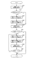
図5は、第1の実施の形態において、画像形成装置100のウォームアップ動作時における画像形成装置100の動作例を示すフローチャートである。なお、ステップS100の処理が行われる前に、ハロゲンヒーター161eによって定着ベルト161aの加熱が開始されるものとする。   FIG. 5 is a flowchart illustrating an operation example of the image forming apparatus 100 during the warm-up operation of the image forming apparatus 100 according to the first embodiment. Note that heating of the fixing belt 161a is started by the halogen heater 161e before the process of step S100 is performed.

まず、制御部200は、温度センサー180から出力された加圧ローラー161dの温度情報を取得する(ステップS100)。次に、制御部200は、取得した温度情報により示される温度が、画像形成時における加圧ローラー161dの目標温度から5℃引いた温度以下であるか否かについて判定する(ステップS120)。   First, the control unit 200 acquires the temperature information of the pressure roller 161d output from the temperature sensor 180 (step S100). Next, the control unit 200 determines whether or not the temperature indicated by the acquired temperature information is equal to or lower than the temperature obtained by subtracting 5 ° C. from the target temperature of the pressure roller 161d during image formation (step S120).

もし、目標温度から5℃引いた温度以下でないと制御部200にて判定された場合(ステップS120にてNO)、画像形成装置100は図6における処理を終了する。一方、目標温度から5℃引いた温度以下であると判定された場合(ステップS120にてYES)、制御部200は、駆動部190を制御することによって、画像形成時における定着ベルト161aおよび定着ローラー161cと加圧ローラー161dとの間の接触圧力(例えば1500N)よりも低い接触圧力(例えば300N)で、定着ベルト161aおよび定着ローラー161cと加圧ローラー161dとを30秒間、接触させる(ステップS140)。   If it is determined by control unit 200 that the temperature is not lower than the temperature obtained by subtracting 5 ° C. from the target temperature (NO in step S120), image forming apparatus 100 ends the process in FIG. On the other hand, when it is determined that the temperature is equal to or lower than the temperature obtained by subtracting 5 ° C. from the target temperature (YES in step S120), control unit 200 controls drive unit 190 to fix fixing belt 161a and fixing roller during image formation. The fixing belt 161a, the fixing roller 161c, and the pressure roller 161d are brought into contact with each other for 30 seconds at a contact pressure (for example, 300 N) lower than the contact pressure between the pressure roller 161d and the pressure roller 161d (for example, 1500 N) (step S140). .

次に、制御部200は、駆動部190を制御することによって、定着ベルト161aおよび定着ローラー161cと加圧ローラー161dとを離間させる(ステップS160)。次に、制御部200は、温度センサー180から出力された加圧ローラー161dの温度情報を取得する(ステップS180)。次に、制御部200は、取得した温度情報により示される温度が、画像形成時における加圧ローラー161dの目標温度から5℃引いた温度以下であるか否かについて判定する(ステップS200)。   Next, the control unit 200 controls the driving unit 190 to separate the fixing belt 161a and the fixing roller 161c from the pressure roller 161d (step S160). Next, the control unit 200 acquires temperature information of the pressure roller 161d output from the temperature sensor 180 (step S180). Next, the control unit 200 determines whether or not the temperature indicated by the acquired temperature information is equal to or lower than the temperature obtained by subtracting 5 ° C. from the target temperature of the pressure roller 161d at the time of image formation (step S200).

もし、目標温度から5℃引いた温度以下であると制御部200にて判定された場合(ステップS200にてYES)、処理はステップS140に遷移する。一方、目標温度から5℃引いた温度以下でないと判定された場合(ステップS200にてNO)、加圧ローラー161dがその後、定着ベルト161aと接触しても定着ベルト161aの温度を大きく低下させない温度に達したと考えられるため、画像形成装置100は図5における処理を終了する。   If control unit 200 determines that the temperature is equal to or lower than the temperature obtained by subtracting 5 ° C. from the target temperature (YES in step S200), the process transitions to step S140. On the other hand, when it is determined that the temperature is not lower than the temperature obtained by subtracting 5 ° C. from the target temperature (NO in step S200), the temperature at which the temperature of fixing belt 161a does not greatly decrease even when pressure roller 161d subsequently contacts fixing belt 161a. Therefore, the image forming apparatus 100 ends the processing in FIG.

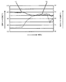
図6は、定着ローラー161cの破壊耐久実験を行った場合における実験結果を示す。実験条件は、ハロゲンヒーター161eによって定着ローラー161cの温度を200℃に制御し、加圧ローラー161dを定着ベルト161aに所定の圧力で押圧する。図6は、加圧ローラー161dと定着ベルト161aとの間の接触圧力(定着ローラー161cのシリコンゴムの変形割合)と、定着ローラー161cが破壊されるまでの時間との関係を示す。   FIG. 6 shows an experimental result when a fracture durability experiment of the fixing roller 161c was performed. The experimental condition is that the temperature of the fixing roller 161c is controlled to 200 ° C. by the halogen heater 161e, and the pressure roller 161d is pressed against the fixing belt 161a with a predetermined pressure. FIG. 6 shows the relationship between the contact pressure between the pressure roller 161d and the fixing belt 161a (the deformation ratio of the silicone rubber of the fixing roller 161c) and the time until the fixing roller 161c is broken.

図6に示すように、加圧ローラー161dと定着ベルト161aとの間の接触圧力が3500Nである場合、定着ローラー161cは10時間で破壊された。また、加圧ローラー161dと定着ベルト161aとの間の接触圧力が3000Nである場合、定着ローラー161cは10時間で破壊された。また、加圧ローラー161dと定着ベルト161aとの間の接触圧力が2500Nである場合、定着ローラー161cは10時間で破壊された。 As shown in FIG. 6, when the contact pressure between the pressure roller 161d and the fixing belt 161a is 3500 N, the fixing roller 161c was broken in 10 hours. The contact pressure between the fixing belt 161a and the pressure roller 161d may be 3000N, fixing roller 161c was destroyed by 10 for 2 hours. The contact pressure between the fixing belt 161a and the pressure roller 161d may be 2500N, fixing roller 161c was destroyed by 10 for 3 hours.

また、加圧ローラー161dと定着ベルト161aとの間の接触圧力が1500Nである場合、定着ローラー161cは10時間で破壊された。また、加圧ローラー161dと定着ベルト161aとの間の接触圧力が300Nである場合、定着ローラー161cは10時間で破壊された。なお、加圧ローラー161dと定着ベルト161aとの間の接触圧力が1500Nまたは300Nである場合の破壊時間は、接触圧力が3500N〜2500Nである場合の破壊時間を示す近似式を求め、その近似式から推定した時間である。 The contact pressure between the fixing belt 161a and the pressure roller 161d may be 1500 N, fixing roller 161c was destroyed by 10 for 4 hours. The contact pressure between the fixing belt 161a and the pressure roller 161d may be 300N, fixing roller 161c was destroyed at 106 hours. Note that the break time when the contact pressure between the pressure roller 161d and the fixing belt 161a is 1500 N or 300 N is obtained by calculating an approximate expression indicating the break time when the contact pressure is 3500 N to 2500 N. It is the time estimated from

図6に示す結果は、実際の画像形成装置100における耐久性能ではなく、あくまで耐久性能の目安である。しかし、図6に示すように接触圧力を300N程度に設定することによって、画像形成時における接触力(1500N)と比較して定着ローラー161cの耐久性能が大幅に増すことが想定される。よって、ウォームアップ動作時に、画像形成時における定着ベルト161aと加圧ローラー161dとの間の接触圧力よりも低い接触圧力で接触させることにより、定着ローラー161cの耐久性能を大幅に増すことが可能となる。   The result shown in FIG. 6 is not a durability performance in the actual image forming apparatus 100 but a standard of the durability performance. However, by setting the contact pressure to about 300 N as shown in FIG. 6, it is assumed that the durability performance of the fixing roller 161 c is greatly increased compared to the contact force (1500 N) during image formation. Therefore, during the warm-up operation, the durability performance of the fixing roller 161c can be greatly increased by contacting with a contact pressure lower than the contact pressure between the fixing belt 161a and the pressure roller 161d during image formation. Become.

以上詳しく説明したように、第1の実施の形態では、画像形成装置100のウォームアップ動作時に、加圧ローラー161dの温度が画像形成時の目標温度を大きく下回る場合、加圧ローラー161dの温度が当該目標温度近傍に達するまで、定着ベルト161aおよび定着ローラー161cと加圧ローラー161dとを接触させる。具体的には、画像形成時における定着ベルト161aおよび定着ローラー161cと加圧ローラー161dとの間の接触圧力(例えば1500N)よりも低い接触圧力(例えば300N)で接触させる。   As described above in detail, in the first embodiment, during the warm-up operation of the image forming apparatus 100, when the temperature of the pressure roller 161d is significantly lower than the target temperature during image formation, the temperature of the pressure roller 161d is The fixing belt 161a, the fixing roller 161c, and the pressure roller 161d are brought into contact until reaching the vicinity of the target temperature. Specifically, the contact is made at a contact pressure (for example, 300 N) lower than the contact pressure (for example, 1500 N) between the fixing belt 161 a and the fixing roller 161 c and the pressure roller 161 d during image formation.

このように構成した第1の実施の形態によれば、プリント開始時における定着ベルト161aおよび定着ローラー161cと、加圧ローラー161dとの間の温度差が小さくなり、定着不良が発生することを防止できる。また、ウォームアップ動作時、定着ベルト161aおよび定着ローラー161cと、加圧ローラー161dとは通常時(画像形成時)より小さい負荷で接触するため、定着ベルト161aおよび定着ローラー161cに耐久劣化が生じにくくなる。以上より、トナー像の定着不良を防止するとともに、加熱部材の耐久劣化を軽減することができる。   According to the first embodiment configured as described above, the temperature difference between the fixing belt 161a and the fixing roller 161c at the start of printing and the pressure roller 161d is reduced, thereby preventing a fixing failure from occurring. it can. Further, during the warm-up operation, the fixing belt 161a and the fixing roller 161c and the pressure roller 161d are in contact with each other with a load smaller than that at the normal time (during image formation), so that the durability deterioration of the fixing belt 161a and the fixing roller 161c hardly occurs. Become. As described above, the fixing failure of the toner image can be prevented and the durability deterioration of the heating member can be reduced.

なお、上記第1の実施の形態において、ウォームアップ動作時、図4に示すように、定着ローラー161cの芯金に接触するように設けられた温度センサー230の温度検出値が所定温度未満である場合、画像形成時における定着ベルト161aおよび定着ローラー161cと加圧ローラー161dとの間の接触圧力と略同一の接触圧力で、定着ベルト161aおよび定着ローラー161cと加圧ローラー161dとを接触させても良い。所定温度とは、例えば、画像形成装置100の外面に設置され、外気温度を検出する温度センサー240の温度検出値に8℃加算した温度である。図7は、画像形成装置100のウォームアップ動作時における画像形成装置100の動作例を示すフローチャートである。なお、ステップS210の処理が行われる前に、ハロゲンヒーター161eによって定着ベルト161aの加熱が開始されるものとする。   In the first embodiment, during the warm-up operation, as shown in FIG. 4, the temperature detection value of the temperature sensor 230 provided so as to come into contact with the core of the fixing roller 161c is less than a predetermined temperature. In this case, even when the fixing belt 161a, the fixing roller 161c, and the pressure roller 161d are brought into contact with each other at substantially the same contact pressure as that between the fixing belt 161a and the fixing roller 161c and the pressure roller 161d during image formation. good. The predetermined temperature is, for example, a temperature obtained by adding 8 ° C. to the temperature detection value of the temperature sensor 240 that is installed on the outer surface of the image forming apparatus 100 and detects the outside air temperature. FIG. 7 is a flowchart illustrating an operation example of the image forming apparatus 100 during the warm-up operation of the image forming apparatus 100. Note that heating of the fixing belt 161a is started by the halogen heater 161e before the process of step S210 is performed.

まず、制御部200は、温度センサー230から出力された定着ローラー161cの温度情報を取得する(ステップS210)。次に、制御部200は、取得した温度情報により示される温度が、所定温度未満であるか否かについて判定する(ステップS215)。定着ローラー161cの温度が所定温度未満である状況としては、例えば、朝一番に画像形成装置100の電源を投入した直後や、冬場の昼間に画像形成装置100の電源を落としておき夜に電源を投入した直後、言い換えると画像形成装置100の電源オフ後に長時間が経過したときなど、定着ユニット161が外気でかなり冷えきった状況が挙げられる。   First, the control unit 200 acquires temperature information of the fixing roller 161c output from the temperature sensor 230 (step S210). Next, the control unit 200 determines whether or not the temperature indicated by the acquired temperature information is less than a predetermined temperature (step S215). As a situation where the temperature of the fixing roller 161c is lower than a predetermined temperature, for example, immediately after turning on the power of the image forming apparatus 100 first in the morning or after turning off the power of the image forming apparatus 100 during the daytime in winter, the power is turned on at night. Immediately after being turned on, in other words, when a long time has passed after the image forming apparatus 100 is turned off, the fixing unit 161 is considerably cooled by the outside air.

もし、所定温度未満でないと制御部200にて判定された場合(ステップS215にてNO)、処理はステップS230に遷移する。一方、所定温度未満であると判定された場合(ステップS215にてYES)、制御部200は、駆動部190を制御することによって、画像形成時における定着ベルト161aおよび定着ローラー161cと加圧ローラー161dとの間の接触圧力(例えば1500N)と略同一の接触圧力で、定着ベルト161aおよび定着ローラー161cと加圧ローラー161dとを60秒間、接触させる(ステップS220)。   If control unit 200 determines that the temperature is not lower than the predetermined temperature (NO in step S215), the process transitions to step S230. On the other hand, when it is determined that the temperature is lower than the predetermined temperature (YES in step S215), control unit 200 controls drive unit 190 to thereby fix fixing belt 161a, fixing roller 161c and pressure roller 161d during image formation. The fixing belt 161a, the fixing roller 161c, and the pressure roller 161d are brought into contact with each other for 60 seconds at a contact pressure substantially equal to the contact pressure (for example, 1500 N) (step S220).

次に、制御部200は、駆動部190を制御することによって、定着ベルト161aおよび定着ローラー161cと加圧ローラー161dとを離間させる(ステップS225)。その後、処理はステップS230に遷移する。   Next, the control unit 200 controls the driving unit 190 to separate the fixing belt 161a, the fixing roller 161c, and the pressure roller 161d (step S225). Thereafter, the process proceeds to step S230.

ステップS230では、制御部200は、温度センサー180から出力された加圧ローラー161dの温度情報を取得する(ステップS230)。次に、制御部200は、取得した温度情報により示される温度が、画像形成時における加圧ローラー161dの目標温度から5℃引いた温度以下であるか否かについて判定する(ステップS235)。   In step S230, the control unit 200 acquires temperature information of the pressure roller 161d output from the temperature sensor 180 (step S230). Next, the control unit 200 determines whether or not the temperature indicated by the acquired temperature information is equal to or lower than a temperature obtained by subtracting 5 ° C. from the target temperature of the pressure roller 161d during image formation (step S235).

もし、目標温度から5℃引いた温度以下でないと制御部200にて判定された場合(ステップS235にてNO)、画像形成装置100は、図7における処理を終了する。一方、目標温度から5℃引いた温度以下であると判定された場合(ステップS235にてYES)、制御部200は、駆動部190を制御することによって、画像形成時における定着ベルト161aおよび定着ローラー161cと加圧ローラー161dとの間の接触圧力よりも低い接触圧力(例えば300N)で、定着ベルト161aおよび定着ローラー161cと加圧ローラー161dとを30秒間、接触させる(ステップS240)。   If it is determined by control unit 200 that the temperature is not lower than the target temperature minus 5 ° C. (NO in step S235), image forming apparatus 100 ends the process in FIG. On the other hand, when it is determined that the temperature is equal to or lower than the temperature obtained by subtracting 5 ° C. from the target temperature (YES in step S235), control unit 200 controls drive unit 190 to control fixing belt 161a and fixing roller during image formation. The fixing belt 161a, the fixing roller 161c, and the pressure roller 161d are brought into contact with each other for 30 seconds at a contact pressure (for example, 300 N) lower than the contact pressure between the 161c and the pressure roller 161d (step S240).

次に、制御部200は、駆動部190を制御することによって、定着ベルト161aおよび定着ローラー161cと加圧ローラー161dとを離間させる(ステップS245)。次に、制御部200は、温度センサー180から出力された加圧ローラー161dの温度情報を取得する(ステップS250)。次に、制御部200は、取得した温度情報により示される温度が、画像形成時における加圧ローラー161dの目標温度から5℃引いた温度以下であるか否かについて判定する(ステップS255)。   Next, the control unit 200 controls the driving unit 190 to separate the fixing belt 161a and the fixing roller 161c from the pressure roller 161d (step S245). Next, the controller 200 acquires temperature information of the pressure roller 161d output from the temperature sensor 180 (step S250). Next, the control unit 200 determines whether or not the temperature indicated by the acquired temperature information is equal to or lower than a temperature obtained by subtracting 5 ° C. from the target temperature of the pressure roller 161d at the time of image formation (step S255).

もし、目標温度から5℃引いた温度以下であると制御部200にて判定された場合(ステップS255にてYES)、処理はステップS240に遷移する。一方、目標温度から5℃引いた温度以下でないと判定された場合(ステップS255にてNO)、加圧ローラー161dがその後、定着ベルト161aと接触しても定着ベルト161aの温度を大きく低下させない温度に達したと考えられるため、画像形成装置100は図7における処理を終了する。   If control unit 200 determines that the temperature is equal to or lower than the temperature obtained by subtracting 5 ° C. from the target temperature (YES in step S255), the process transitions to step S240. On the other hand, when it is determined that the temperature is not lower than the temperature obtained by subtracting 5 ° C. from the target temperature (NO in step S255), the temperature at which the pressure roller 161d does not greatly decrease the temperature of the fixing belt 161a even if it comes into contact with the fixing belt 161a thereafter Therefore, the image forming apparatus 100 ends the processing in FIG.

なお、図7のフローチャートにおいて、定着ローラー161cの代わりに、加圧ローラー161dの温度検出値が所定温度未満である場合、画像形成時における定着ベルト161aおよび定着ローラー161cと加圧ローラー161dとの間の接触圧力と略同一の接触圧力で、定着ベルト161aおよび定着ローラー161cと加圧ローラー161dとを接触させても良い。また、画像形成装置100の電源オフ後における経過時間によって定着ローラー161cの温度の下がり具合が推定できるのであれば、当該経過時間が所定時間以上であるか否かに応じて、画像形成時における定着ベルト161aおよび定着ローラー161cと加圧ローラー161dとの間の接触圧力と略同一の接触圧力で接触させるか否かについて判断しても良い。ここで、画像形成装置100の使用国によって、環境温度が異なり、電源オフ後における経過時間が同じでも定着ローラー161cの温度の下がり具合が異なることが想定される。そこで、画像形成装置100の使用国の環境温度に応じて、画像形成時における定着ベルト161aおよび定着ローラー161cと加圧ローラー161dとの間の接触圧力と略同一の接触圧力で接触させるか否かを判断するための、電源オフ後における経過時間を変えることが好ましい。   In the flowchart of FIG. 7, when the temperature detection value of the pressure roller 161d is lower than the predetermined temperature instead of the fixing roller 161c, the fixing belt 161a and the fixing roller 161c and the pressure roller 161d are formed during image formation. The fixing belt 161a, the fixing roller 161c, and the pressure roller 161d may be brought into contact with each other at substantially the same contact pressure. If the temperature drop of the fixing roller 161c can be estimated from the elapsed time after the image forming apparatus 100 is turned off, the fixing at the time of image formation depends on whether the elapsed time is equal to or longer than a predetermined time. It may be determined whether or not the belt 161a, the fixing roller 161c, and the pressure roller 161d are contacted with substantially the same contact pressure. Here, it is assumed that the temperature of the fixing roller 161c varies depending on the country in which the image forming apparatus 100 is used, even if the environmental temperature is different and the elapsed time after the power is turned off is the same. Therefore, according to the environmental temperature of the country in which the image forming apparatus 100 is used, whether or not the contact is made with substantially the same contact pressure as the contact pressure between the fixing belt 161a and the fixing roller 161c and the pressure roller 161d during image formation. It is preferable to change the elapsed time after the power is turned off to determine the above.

図7に示す処理を行うことによって、図5に示す処理を行う場合と比べて、加圧ローラー161dをより短時間で昇温させることが可能となり、ひいてはウォームアップ動作時間をより短縮することができる。したがって、定着ユニット161が朝一などの冷却した状態から定着動作を行う場合において、定着不良の発生をより防止することができる。   By performing the process shown in FIG. 7, it becomes possible to raise the temperature of the pressure roller 161 d in a shorter time than in the case of performing the process shown in FIG. 5, and thus the warm-up operation time can be further shortened. it can. Therefore, when the fixing unit 161 performs the fixing operation from a cooled state such as in the morning, it is possible to further prevent the occurrence of fixing failure.

また、上記第1の実施の形態では、ウォームアップ動作時に、定着ベルト161aおよび定着ローラー161cと加圧ローラー161dとを30秒間、接触させる例について説明したが、本発明はこれに限定されない。例えば、図8に示すように、画像形成時における加圧ローラー161dの目標温度と、現在の加圧ローラー161dの温度との差分ΔTに応じて接触時間を決定しても良い。この場合、加圧ローラー161dの温度がなるべく速く目標温度近傍に達するようにするため、差分ΔTが大きくなるにつれて接触時間を長くするのが望ましい。   In the first embodiment, the example in which the fixing belt 161a, the fixing roller 161c, and the pressure roller 161d are brought into contact with each other for 30 seconds during the warm-up operation has been described. However, the present invention is not limited to this. For example, as shown in FIG. 8, the contact time may be determined according to the difference ΔT between the target temperature of the pressure roller 161d during image formation and the current temperature of the pressure roller 161d. In this case, it is desirable to increase the contact time as the difference ΔT increases so that the temperature of the pressure roller 161d reaches the vicinity of the target temperature as quickly as possible.

また、定着ベルト161aおよび定着ローラー161cと加圧ローラー161dとを接触させる場合、加圧ローラー161dの温度上昇率は、加圧ローラー161dが高くなるにつれて小さくなる。そのため、例えば、加圧ローラー161dの目標温度が100℃を超える場合、図8に示す接触時間に30秒加えた時間を接触時間に決定することで、加圧ローラー161dの温度がなるべく速く目標温度近傍に達するようにしても良い。   When the fixing belt 161a and the fixing roller 161c are brought into contact with the pressure roller 161d, the rate of temperature increase of the pressure roller 161d decreases as the pressure roller 161d increases. Therefore, for example, when the target temperature of the pressure roller 161d exceeds 100 ° C., by determining the contact time shown in FIG. 8 as the time obtained by adding 30 seconds to the contact time, the temperature of the pressure roller 161d is as fast as possible. You may make it reach near.

また、上記第1の実施の形態において、図4,9に示すように、定着ローラー161cの芯金に接触するように設けられた温度センサー230の検出結果に応じて、定着ベルト161aおよび定着ローラー161cと加圧ローラー161dとの接触時間を決定しても良い。この場合、定着ローラー161cの芯金温度が高いほど、それに接触する加圧ローラー161dの昇温速度が速いため、芯金温度が高くなるにつれて接触時間を短くするのが望ましい。   In the first embodiment, as shown in FIGS. 4 and 9, the fixing belt 161 a and the fixing roller according to the detection result of the temperature sensor 230 provided in contact with the core metal of the fixing roller 161 c. The contact time between 161c and the pressure roller 161d may be determined. In this case, the higher the core temperature of the fixing roller 161c, the faster the temperature rise rate of the pressure roller 161d that contacts the fixing roller 161c. Therefore, it is desirable to shorten the contact time as the core temperature increases.

また、上記第1の実施の形態では、画像形成装置100のウォームアップ動作時に、定着ベルト161aおよび定着ローラー161cと加圧ローラー161dとを300Nの接触圧力で接触させる例について説明したが、本発明はこれに限定されない。定着ベルト161aおよび定着ローラー161cの耐久劣化を考慮すれば、より低い接触圧力で接触させることが望ましく、定着ベルト161aおよび定着ローラー161cと加圧ローラー161dとを当接に近い状態で接触させても良い。   In the first embodiment, the example in which the fixing belt 161a, the fixing roller 161c, and the pressure roller 161d are brought into contact with each other with a contact pressure of 300 N during the warm-up operation of the image forming apparatus 100 has been described. Is not limited to this. Considering the durability deterioration of the fixing belt 161a and the fixing roller 161c, it is desirable to make contact with a lower contact pressure. Even if the fixing belt 161a, the fixing roller 161c and the pressure roller 161d are brought into contact with each other in a state close to contact, good.

(第2の実施の形態)
以下、本発明に係る第2の実施の形態を図面に基づいて詳細に説明する。画像形成装置100の基本構成については、第1の実施の形態と同様であるので説明を省略する。
(Second Embodiment)
Hereinafter, a second embodiment according to the present invention will be described in detail with reference to the drawings. Since the basic configuration of the image forming apparatus 100 is the same as that of the first embodiment, the description thereof is omitted.

図10〜12に示すように画像形成装置100は、図2に示す構成に加えて、温度センサー250a,250bを備える。温度センサー250aは、定着ベルト161aおよび加熱ローラー161bの上方、かつ、用紙幅方向における図面左方位置に設けられている。温度センサー250aは、定着ベルト161aおよび加熱ローラー161bの上方、かつ、用紙幅方向における中心位置に設けられている。   As shown in FIGS. 10 to 12, the image forming apparatus 100 includes temperature sensors 250 a and 250 b in addition to the configuration shown in FIG. 2. The temperature sensor 250a is provided above the fixing belt 161a and the heating roller 161b and at the left side of the drawing in the paper width direction. The temperature sensor 250a is provided above the fixing belt 161a and the heating roller 161b and at the center position in the paper width direction.

温度センサー250aは、定着ベルト161aの用紙幅方向中央部の温度を検出し、その検出した温度情報を制御部200に出力する。温度センサー250bは、定着ベルト161aの用紙幅方向端部の温度を検出し、その検出した温度情報を制御部200に出力する。制御部200は、温度センサー250aから出力された温度情報により示される温度と、温度センサー250bから出力された温度情報により示される温度との平均値を求め、その求めた平均値を定着ベルト161aの温度と判断する。   The temperature sensor 250 a detects the temperature of the central portion of the fixing belt 161 a in the paper width direction, and outputs the detected temperature information to the control unit 200. The temperature sensor 250 b detects the temperature of the end of the fixing belt 161 a in the paper width direction, and outputs the detected temperature information to the control unit 200. The control unit 200 obtains an average value of the temperature indicated by the temperature information output from the temperature sensor 250a and the temperature indicated by the temperature information output from the temperature sensor 250b, and uses the obtained average value of the fixing belt 161a. Judge as temperature.

加圧ローラー161dは、図12に示すように、例えば、700Wのハロゲンヒーター161fを内蔵している。つまり、ハロゲンヒーター161fは、加熱ローラー161bが備えるハロゲンヒーター161eよりも昇温能力が低い。加圧ローラー161dは、定着ベルト161aの温度を安定させる(定着ベルト161aからの放熱を抑制する)ために、ハロゲンヒーター161fによって所定の温度(例えば100℃)に保持される。ハロゲンヒーター161fの温度は、制御部200によって制御される。なお、ハロゲンヒーター161fは、加熱源として機能する。   As shown in FIG. 12, the pressure roller 161d incorporates a 700 W halogen heater 161f, for example. That is, the halogen heater 161f has a lower temperature raising capability than the halogen heater 161e included in the heating roller 161b. The pressure roller 161d is held at a predetermined temperature (for example, 100 ° C.) by the halogen heater 161f in order to stabilize the temperature of the fixing belt 161a (suppress heat dissipation from the fixing belt 161a). The temperature of the halogen heater 161f is controlled by the control unit 200. The halogen heater 161f functions as a heating source.

本実施の形態では、制御部200は、画像形成装置100のウォームアップ動作時に、加圧ローラー161dの温度が画像形成時の目標温度を大きく下回る場合、加圧ローラー161dの温度が当該目標温度近傍に達するまで、定着ベルト161aおよび定着ローラー161cと加圧ローラー161dとを接触させるとともに、ハロゲンヒーター161fによって加圧ローラー161dを昇温させる。具体的には、画像形成時における定着ベルト161aおよび定着ローラー161cと加圧ローラー161dとの間の接触圧力(例えば1500N)よりも低い接触圧力(例えば300N)で接触させる。   In the present embodiment, when the temperature of the pressure roller 161d is significantly lower than the target temperature at the time of image formation during the warm-up operation of the image forming apparatus 100, the control unit 200 causes the temperature of the pressure roller 161d to be close to the target temperature. Until the fixing belt 161a and the fixing roller 161c are brought into contact with the pressure roller 161d, and the temperature of the pressure roller 161d is increased by the halogen heater 161f. Specifically, the contact is made at a contact pressure (for example, 300 N) lower than the contact pressure (for example, 1500 N) between the fixing belt 161 a and the fixing roller 161 c and the pressure roller 161 d during image formation.

図13は、第2の実施の形態において、画像形成装置100のウォームアップ動作時における画像形成装置100の動作例を示すフローチャートである。なお、ステップS600の処理が行われる前に、ハロゲンヒーター161eによって定着ベルト161aの加熱が開始されるものとする。   FIG. 13 is a flowchart illustrating an operation example of the image forming apparatus 100 during the warm-up operation of the image forming apparatus 100 in the second embodiment. Note that heating of the fixing belt 161a is started by the halogen heater 161e before the process of step S600 is performed.

まず、制御部200は、温度センサー250a,250bから出力された定着ベルト161aの温度情報を取得する(ステップS300)。そして、制御部200は、温度センサー250aから出力された温度情報により示される温度と、温度センサー250bから出力された温度情報により示される温度との平均値を求め、その求めた平均値を定着ベルト161aの温度と判断する。   First, the control unit 200 acquires temperature information of the fixing belt 161a output from the temperature sensors 250a and 250b (step S300). Then, the control unit 200 obtains an average value of the temperature indicated by the temperature information output from the temperature sensor 250a and the temperature indicated by the temperature information output from the temperature sensor 250b, and uses the obtained average value for the fixing belt. The temperature is determined to be 161a.

次に、制御部200は、定着ベルト161aの温度が、画像形成時における定着ベルト161aの目標温度に達したか否かについて判定する(ステップS320)。もし、定着ベルト161aの目標温度に達していないと制御部200にて判定された場合(ステップS320にてNO)、処理はステップS300に遷移する。   Next, the control unit 200 determines whether or not the temperature of the fixing belt 161a has reached the target temperature of the fixing belt 161a during image formation (step S320). If control unit 200 determines that target temperature of fixing belt 161a has not been reached (NO in step S320), the process transitions to step S300.

一方、定着ベルト161aの目標温度に達したと判定された場合(ステップS320にてYES)、制御部200は、温度センサー180から出力された加圧ローラー161dの温度情報を取得する(ステップS340)。次に、制御部200は、取得した温度情報により示される温度が、画像形成時における加圧ローラー161dの目標温度から10℃引いた温度以下であるか否かについて判定する(ステップS360)。   On the other hand, when it is determined that the target temperature of fixing belt 161a has been reached (YES in step S320), control unit 200 acquires temperature information of pressure roller 161d output from temperature sensor 180 (step S340). . Next, the control unit 200 determines whether or not the temperature indicated by the acquired temperature information is equal to or lower than a temperature obtained by subtracting 10 ° C. from the target temperature of the pressure roller 161d during image formation (step S360).

もし、目標温度から10℃引いた温度以下でないと制御部200にて判定された場合(ステップS360にてNO)、画像形成装置100は図13における処理を終了する。一方、目標温度から10℃引いた温度以下であると判定された場合(ステップS360にてYES)、制御部200は、駆動部190を制御することによって、画像形成時における定着ベルト161aおよび定着ローラー161cと加圧ローラー161dとの間の接触圧力(例えば1500N)よりも低い接触圧力(例えば300N)で、定着ベルト161aおよび定着ローラー161cと加圧ローラー161dとの接触を開始する(ステップS380)。   If it is determined by control unit 200 that the temperature is not lower than the target temperature minus 10 ° C. (NO in step S360), image forming apparatus 100 ends the processing in FIG. On the other hand, when it is determined that the temperature is equal to or lower than the temperature obtained by subtracting 10 ° C. from the target temperature (YES in step S360), control unit 200 controls drive unit 190 to fix fixing belt 161a and fixing roller during image formation. The contact between the fixing belt 161a and the fixing roller 161c and the pressure roller 161d is started at a contact pressure (for example, 300 N) lower than the contact pressure between the pressure roller 161d and the pressure roller 161d (for example, 1500 N) (step S380).

次に、制御部200は、加圧ローラー161dの昇温速度を向上させるため、ハロゲンヒーター161fへの電源を投入する(ステップS400)。次に、制御部200は、温度センサー180から出力された加圧ローラー161dの温度情報を取得する(ステップS420)。次に、制御部200は、取得した温度情報により示される温度が、画像形成時における加圧ローラー161dの目標温度に5℃加算した温度以上であるか否かについて判定する(ステップS440)。   Next, the control unit 200 turns on the power to the halogen heater 161f in order to improve the temperature increase rate of the pressure roller 161d (step S400). Next, the controller 200 acquires temperature information of the pressure roller 161d output from the temperature sensor 180 (step S420). Next, the control unit 200 determines whether or not the temperature indicated by the acquired temperature information is equal to or higher than the temperature obtained by adding 5 ° C. to the target temperature of the pressure roller 161d at the time of image formation (step S440).

もし、目標温度に5℃加算した温度以下でないと制御部200にて判定された場合(ステップS440にてNO)、処理はステップS420に遷移する。一方、目標温度に5℃加算した温度以上であると判定された場合(ステップS440にてYES)、制御部200は、駆動部190を制御することによって、定着ベルト161aおよび定着ローラー161cと加圧ローラー161dとを離間させる(ステップS460)。ステップS460の処理が完了することによって、画像形成装置100は図13における処理を終了する。   If it is determined by control unit 200 that the temperature is not lower than the target temperature added by 5 ° C. (NO in step S440), the process transitions to step S420. On the other hand, when it is determined that the temperature is equal to or higher than the temperature obtained by adding 5 ° C. to the target temperature (YES in step S440), control unit 200 controls drive unit 190 to press fixing belt 161a and fixing roller 161c with pressure. The roller 161d is separated (step S460). When the process of step S460 is completed, the image forming apparatus 100 ends the process in FIG.

図14は、画像形成装置100のウォームアップ動作直後に、定着ベルト161aおよび定着ローラー161cと加圧ローラー161dとを接触させる前後において、定着ベルト161aの温度変化および加圧ローラー161dの温度変化を示す。図14において、曲線L3は、定着ベルト161aの温度変化を示す。また、曲線L4は、加圧ローラー161dの温度変化を示す。図14に示す例では、ウォームアップ動作直後、加圧ローラー161dの温度は約105℃と高い。したがって、定着ベルト161aおよび定着ローラー161cと加圧ローラー161dとを接触させた場合、定着ベルト161aの温度低下を5℃程度に抑えることができ、定着不良が発生することを防止できる。   FIG. 14 shows the temperature change of the fixing belt 161a and the temperature change of the pressure roller 161d immediately before and after the fixing belt 161a, the fixing roller 161c, and the pressure roller 161d are brought into contact immediately after the warm-up operation of the image forming apparatus 100. . In FIG. 14, a curve L3 indicates a temperature change of the fixing belt 161a. A curve L4 indicates a temperature change of the pressure roller 161d. In the example shown in FIG. 14, the temperature of the pressure roller 161d is as high as about 105 ° C. immediately after the warm-up operation. Therefore, when the fixing belt 161a, the fixing roller 161c, and the pressure roller 161d are brought into contact with each other, the temperature drop of the fixing belt 161a can be suppressed to about 5 ° C., and the occurrence of fixing failure can be prevented.

以上詳しく説明したように、第2の実施の形態では、画像形成装置100のウォームアップ動作時に、加圧ローラー161dの温度が画像形成時の目標温度を大きく下回る場合、加圧ローラー161dの温度が当該目標温度近傍に達するまで、定着ベルト161aおよび定着ローラー161cと加圧ローラー161dとを接触させるとともに、ハロゲンヒーター161fによって加圧ローラー161dを昇温させる。これにより、第1の実施の形態で説明した効果に加えて、加圧ローラー161dを短時間で昇温させることが可能となり、ひいてはウォームアップ動作時間をより短縮することができる。   As described above in detail, in the second embodiment, when the temperature of the pressure roller 161d is significantly lower than the target temperature during image formation during the warm-up operation of the image forming apparatus 100, the temperature of the pressure roller 161d is increased. The fixing belt 161a, the fixing roller 161c, and the pressure roller 161d are brought into contact with each other until the temperature reaches the target temperature, and the pressure roller 161d is heated by the halogen heater 161f. Thereby, in addition to the effect demonstrated in 1st Embodiment, it becomes possible to heat-up the pressurization roller 161d in a short time, and, by extension, warm-up operation time can be shortened further.

なお、上記第2の実施の形態では、加圧ローラー161dの温度が当該目標温度近傍に達するまで、定着ベルト161aおよび定着ローラー161cと加圧ローラー161dとの接触状態を維持する例について説明したが、本発明はこれに限定されない。例えば、第1の実施の形態のように、加圧ローラー161dの温度が当該目標温度近傍に達するまで、定着ベルト161aおよび定着ローラー161cと加圧ローラー161dとを所定時間、接触させては離間する処理を繰り返すようにしても良い。この場合、定着ローラー161cの芯金に接触するように設けられた温度センサー230の検出結果に応じて、定着ベルト161aおよび定着ローラー161cと加圧ローラー161dとの接触時間を決定しても良い。   In the second embodiment, the example in which the contact state between the fixing belt 161a and the fixing roller 161c and the pressure roller 161d is maintained until the temperature of the pressure roller 161d reaches the vicinity of the target temperature has been described. However, the present invention is not limited to this. For example, as in the first embodiment, the fixing belt 161a, the fixing roller 161c, and the pressure roller 161d are brought into contact with each other for a predetermined time until the temperature of the pressure roller 161d reaches the vicinity of the target temperature. The process may be repeated. In this case, the contact time between the fixing belt 161a and the fixing roller 161c and the pressure roller 161d may be determined in accordance with the detection result of the temperature sensor 230 provided so as to contact the core of the fixing roller 161c.

また、上記第1および第2の実施の形態では、ウォームアップ動作時に、画像形成時の接触圧力よりも低い接触圧力で定着ベルト161aおよび定着ローラー161cと、加圧ローラー161dとを接触させる例について説明したが、本発明はこれに限定されない。例えば、ウォームアップ動作完了後のアイドリング動作(待機動作)時に、画像形成時の接触圧力よりも低い接触圧力、または、画像形成時の接触圧力と略同一の接触圧力で定着ベルト161aおよび定着ローラー161cと、加圧ローラー161dとを接触させても良い。この構成により、アイドリング動作終了後のプリント開始時においても、定着ベルト161aおよび定着ローラー161cと、加圧ローラー161dとの間の温度差が小さくなり、定着不良が発生することを防止できる。   In the first and second embodiments, an example in which the fixing belt 161a and the fixing roller 161c are brought into contact with the pressure roller 161d with a contact pressure lower than the contact pressure during image formation during the warm-up operation. Although described, the present invention is not limited to this. For example, at the idling operation (standby operation) after completion of the warm-up operation, the fixing belt 161a and the fixing roller 161c are contact pressure lower than the contact pressure at the time of image formation or substantially the same contact pressure at the time of image formation. And the pressure roller 161d may be brought into contact with each other. With this configuration, even at the start of printing after completion of the idling operation, temperature differences among the fixing belt 161a, the fixing roller 161c, and the pressure roller 161d are reduced, and it is possible to prevent a fixing failure from occurring.

また、上記第1および第2の実施の形態では、加圧ローラー161dを定着ベルト161a側に移動させることによって、定着ベルト161aおよび定着ローラー161cと、加圧ローラー161dとを接触させる例について説明したが、本発明はこれに限定されない。例えば、定着ベルト161aを加圧ローラー161dに移動させても良い。また、加圧ローラー161dおよび定着ベルト161aを互いに近づくように移動させても良い。   In the first and second embodiments, the example in which the fixing belt 161a and the fixing roller 161c are brought into contact with the pressure roller 161d by moving the pressure roller 161d toward the fixing belt 161a has been described. However, the present invention is not limited to this. For example, the fixing belt 161a may be moved to the pressure roller 161d. Further, the pressure roller 161d and the fixing belt 161a may be moved so as to approach each other.

また、上記第1および第2の実施の形態では、ベルト加熱方式の定着ユニット161を用いることとしたが、本発明はこれに限定されない。例えば、定着ユニット161を加熱源を有する定着ローラーと加圧ローラーとで構成してもよい。   In the first and second embodiments, the belt heating type fixing unit 161 is used. However, the present invention is not limited to this. For example, the fixing unit 161 may be composed of a fixing roller having a heating source and a pressure roller.

その他、上記第1および第2の実施の形態は、何れも本発明を実施するにあたっての具体化の一例を示したものに過ぎず、これらによって本発明の技術的範囲が限定的に解釈されてはならないものである。すなわち、本発明はその要旨、またはその主要な特徴から逸脱することなく、様々な形で実施することができる。   In addition, each of the first and second embodiments described above is merely an example of a specific example for carrying out the present invention, and the technical scope of the present invention is interpreted in a limited manner. It must not be. That is, the present invention can be implemented in various forms without departing from the gist or the main features thereof.

100 画像形成装置
161a 定着ベルト
161c 定着ローラー
161d 加圧ローラー
161e,161f ハロゲンヒーター
190 駆動部
200 制御部
DESCRIPTION OF SYMBOLS 100 Image forming apparatus 161a Fixing belt 161c Fixing roller 161d Pressure roller 161e, 161f Halogen heater 190 Drive part 200 Control part

Claims (7)

記録用紙を加熱する加熱部材と、
前記加熱部材との間で前記記録用紙を加圧する加圧部材と、
前記加熱部材と前記加圧部材との接触または離間を行う調整機構と、
ウォームアップ動作時またはアイドリング動作時に、画像形成時における前記加熱部材と前記加圧部材との間の接触圧力よりも低い接触圧力で前記加熱部材と前記加圧部材とを接触させるように前記調整機構を制御する制御部と、
を備える画像形成装置。
A heating member for heating the recording paper;
A pressure member that pressurizes the recording paper with the heating member;
An adjustment mechanism for making contact or separation between the heating member and the pressure member;
The adjusting mechanism is configured to bring the heating member and the pressure member into contact with each other at a contact pressure lower than a contact pressure between the heating member and the pressure member during image formation during a warm-up operation or an idling operation. A control unit for controlling
An image forming apparatus comprising:
前記加圧部材の温度を検出する温度センサーを備え、
前記制御部は、前記ウォームアップ動作時または前記アイドリング動作時、前記温度センサーからの温度検出値に基づいて前記調整機構を制御する請求項1に記載の画像形成装置。
A temperature sensor for detecting the temperature of the pressure member;
The image forming apparatus according to claim 1, wherein the control unit controls the adjustment mechanism based on a temperature detection value from the temperature sensor during the warm-up operation or the idling operation.
前記加熱部材または前記加圧部材の温度を検出する温度センサーを備え、
前記制御部は、前記ウォームアップ動作時または前記アイドリング動作時に、前記温度センサーからの温度検出値が所定温度未満である場合、画像形成時における前記加熱部材と前記加圧部材との間の接触圧力と略同一の接触圧力で前記加熱部材と前記加圧部材とを接触させるように前記調整機構を制御する一方、前記温度センサーの温度検出値が所定温度以上である場合、画像形成時における前記加熱部材と前記加圧部材との間の接触圧力よりも低い接触圧力で前記加熱部材と前記加圧部材とを接触させるように前記調整機構を制御する請求項1に記載の画像形成装置。
A temperature sensor for detecting the temperature of the heating member or the pressure member;
When the temperature detection value from the temperature sensor is lower than a predetermined temperature during the warm-up operation or the idling operation, the control unit may contact pressure between the heating member and the pressure member during image formation. The adjustment mechanism is controlled so that the heating member and the pressure member are brought into contact with each other at substantially the same contact pressure, and when the temperature detection value of the temperature sensor is equal to or higher than a predetermined temperature, the heating during image formation The image forming apparatus according to claim 1, wherein the adjustment mechanism is controlled so that the heating member and the pressure member are brought into contact with each other with a contact pressure lower than a contact pressure between the member and the pressure member.
前記制御部は、前記ウォームアップ動作時または前記アイドリング動作時に、前記画像形成装置の電源オフ後における経過時間が所定時間以上である場合、画像形成時における前記加熱部材と前記加圧部材との間の接触圧力と略同一の接触圧力で前記加熱部材と前記加圧部材とを接触させるように前記調整機構を制御する一方、前記経過時間が所定時間未満である場合、画像形成時における前記加熱部材と前記加圧部材との間の接触圧力よりも低い接触圧力で前記加熱部材と前記加圧部材とを接触させるように前記調整機構を制御する請求項1に記載の画像形成装置。   In the warm-up operation or the idling operation, when the elapsed time after the power-off of the image forming apparatus is equal to or longer than a predetermined time, the control unit is provided between the heating member and the pressure member during image formation. When the adjustment mechanism is controlled so that the heating member and the pressure member are brought into contact with each other at substantially the same contact pressure as the contact pressure, the heating member during image formation when the elapsed time is less than a predetermined time The image forming apparatus according to claim 1, wherein the adjustment mechanism is controlled so that the heating member and the pressure member are brought into contact with each other with a contact pressure lower than a contact pressure between the pressure member and the pressure member. 前記制御部は、前記温度センサーからの温度検出値と目標温度とを比較し、前記加圧部材の温度が前記目標温度に達するまで前記加熱部材と前記加圧部材とを接触させるように前記調整機構を制御する請求項2〜4の何れか1項に記載の画像形成装置。   The control unit compares a temperature detection value from the temperature sensor with a target temperature, and adjusts the heating member and the pressure member to contact each other until the temperature of the pressure member reaches the target temperature. The image forming apparatus according to claim 2, wherein the mechanism is controlled. 前記加圧部材を加熱する加熱源を備え、
前記制御部は、前記ウォームアップ動作時または前記アイドリング動作時に、前記加熱源への電源を投入する請求項5に記載の画像形成装置。
A heating source for heating the pressure member;
The image forming apparatus according to claim 5, wherein the control unit powers on the heating source during the warm-up operation or the idling operation.
記録用紙を加熱する加熱部材と、
前記加熱部材との間で前記記録用紙を加圧する加圧部材と、
前記加熱部材と前記加圧部材との接触または離間を行う調整機構と、
を備える画像形成装置の制御方法であって、
前記制御部が、ウォームアップ動作時またはアイドリング動作時に、画像形成時における前記加熱部材と前記加圧部材との間の接触圧力よりも低い接触圧力で前記加熱部材と前記加圧部材とを接触させるように前記調整機構を制御する制御方法。
A heating member for heating the recording paper;
A pressure member that pressurizes the recording paper with the heating member;
An adjustment mechanism for making contact or separation between the heating member and the pressure member;
An image forming apparatus control method comprising:
The controller brings the heating member and the pressure member into contact with each other at a contact pressure lower than the contact pressure between the heating member and the pressure member during image formation during a warm-up operation or an idling operation. A control method for controlling the adjustment mechanism as described above.
JP2012208184A 2012-04-12 2012-09-21 Image forming device and control method Pending JP2013235231A (en)

Priority Applications (3)

Application Number Priority Date Filing Date Title
JP2012208184A JP2013235231A (en) 2012-04-12 2012-09-21 Image forming device and control method
US13/845,991 US9002228B2 (en) 2012-04-12 2013-03-18 Image forming apparatus with control section to control contact pressure between heating member and pressure member and control method thereof
CN201310120070.6A CN103823345B (en) 2012-04-12 2013-04-09 Image processing system and its control method

Applications Claiming Priority (3)

Application Number Priority Date Filing Date Title
JP2012091015 2012-04-12
JP2012208184A JP2013235231A (en) 2012-04-12 2012-09-21 Image forming device and control method

Publications (1)

Publication Number Publication Date
JP2013235231A true JP2013235231A (en) 2013-11-21

Family

ID=49325198

Family Applications (1)

Application Number Title Priority Date Filing Date
JP2012208184A Pending JP2013235231A (en) 2012-04-12 2012-09-21 Image forming device and control method

Country Status (3)

Country Link
US (1) US9002228B2 (en)
JP (1) JP2013235231A (en)
CN (1) CN103823345B (en)

Cited By (2)

* Cited by examiner, † Cited by third party
Publication number Priority date Publication date Assignee Title
JP2017015801A (en) * 2015-06-29 2017-01-19 京セラドキュメントソリューションズ株式会社 Fixing device and image forming apparatus including the same
JP2019124753A (en) * 2018-01-12 2019-07-25 コニカミノルタ株式会社 Fixation device, image formation device, and control method

Families Citing this family (2)

* Cited by examiner, † Cited by third party
Publication number Priority date Publication date Assignee Title
US9291961B1 (en) * 2015-01-21 2016-03-22 Kabushiki Kaisha Toshiba Fixing apparatus and image forming apparatus having the same
JP6229700B2 (en) * 2015-09-18 2017-11-15 コニカミノルタ株式会社 Fixing apparatus, image forming apparatus, and fixing control method

Family Cites Families (25)

* Cited by examiner, † Cited by third party
Publication number Priority date Publication date Assignee Title
JPS6055370A (en) 1983-09-06 1985-03-30 Fuji Xerox Co Ltd Roll fixing device of copying machine
US6078781A (en) * 1998-01-09 2000-06-20 Kabushiki Kaisha Toshiba Fixing device using an induction heating unit
JP2001100575A (en) * 1999-07-23 2001-04-13 Canon Inc Image heating device
US7242881B2 (en) * 2004-05-14 2007-07-10 Konica Minolta Business Technologies, Inc. Image forming apparatus having advanced fixing system
JP4700948B2 (en) * 2004-10-20 2011-06-15 キヤノン株式会社 Image forming apparatus
JP5037871B2 (en) * 2005-07-27 2012-10-03 キヤノン株式会社 Fixing device
JP5230087B2 (en) * 2005-09-12 2013-07-10 キヤノン株式会社 Image forming apparatus
JP4612522B2 (en) 2005-10-13 2011-01-12 日本電信電話株式会社 Change area calculation method, change area calculation device, change area calculation program
JP2007272032A (en) * 2006-03-31 2007-10-18 Canon Inc Image heating device
US20070246457A1 (en) * 2006-04-20 2007-10-25 Kabushiki Kaisha Toshiba Fixing device for image forming apparatus and fixing method
US7623803B2 (en) * 2007-04-19 2009-11-24 Xerox Corporation Fuser system of a xerographic device and a method of fusing an image in a xerographic device including a closed loop control based on the torque of a drive system
JP2009058775A (en) * 2007-08-31 2009-03-19 Konica Minolta Business Technologies Inc Image forming apparatus
US8180240B2 (en) * 2008-03-18 2012-05-15 Lexmark International, Inc. Color belt fuser warm-up time minimization
JP5257691B2 (en) * 2008-08-08 2013-08-07 株式会社リコー Fixing apparatus and image forming apparatus
US7970330B2 (en) * 2008-10-30 2011-06-28 Xerox Corporation Fusers, printing apparatuses and methods of fusing toner on media
US20100166471A1 (en) * 2008-12-31 2010-07-01 Kabushiki Kaisha Toshiba Image forming apparatus and fixing device
US8041245B2 (en) * 2009-08-31 2011-10-18 Xerox Corporation Apparatuses useful in printing and methods of controlling the temperature of surfaces in apparatuses useful in printing
US20110069984A1 (en) * 2009-09-22 2011-03-24 Kabushiki Kaisha Toshiba Fixing device, image forming apparatus and method for fixing image
JP5472605B2 (en) * 2009-10-09 2014-04-16 株式会社リコー Fixing apparatus and image forming apparatus
JP2011095320A (en) * 2009-10-27 2011-05-12 Ricoh Co Ltd Fixing device and image forming apparatus
JP5528194B2 (en) * 2010-04-30 2014-06-25 キヤノン株式会社 Image forming apparatus
US8666270B2 (en) * 2010-06-21 2014-03-04 Ricoh Company, Ltd. Image forming apparatus
JP5610148B2 (en) * 2010-10-18 2014-10-22 株式会社リコー Image forming apparatus
JP5708084B2 (en) * 2011-03-17 2015-04-30 株式会社リコー Fixing device and image forming apparatus having the same
US20120263487A1 (en) * 2011-04-18 2012-10-18 Toshiba Tec Kabushiki Kaisha Fixing device, image forming apparatus using the same and controlling mehod of the same

Cited By (2)

* Cited by examiner, † Cited by third party
Publication number Priority date Publication date Assignee Title
JP2017015801A (en) * 2015-06-29 2017-01-19 京セラドキュメントソリューションズ株式会社 Fixing device and image forming apparatus including the same
JP2019124753A (en) * 2018-01-12 2019-07-25 コニカミノルタ株式会社 Fixation device, image formation device, and control method

Also Published As

Publication number Publication date
CN103823345A (en) 2014-05-28
US9002228B2 (en) 2015-04-07
US20130272736A1 (en) 2013-10-17
CN103823345B (en) 2017-05-31

Similar Documents

Publication Publication Date Title
JP5825298B2 (en) Image forming apparatus
JP2007248725A (en) Fixing device, image forming apparatus, temperature control method for fixing device, temperature control program and temperature control program recording medium
JP2015108764A (en) Image forming device
JP2013235231A (en) Image forming device and control method
JP4306557B2 (en) Image forming system
US10082756B2 (en) Image forming apparatus and image forming system
JP6079500B2 (en) Fixing apparatus and image forming apparatus
JP5803885B2 (en) Image forming apparatus and image forming method
US10437186B2 (en) Fixing device and image forming apparatus
JP2019101253A (en) Image forming apparatus and distance control method
JP5842797B2 (en) Image forming apparatus and swing control method
JP6604026B2 (en) Image forming apparatus, image forming system, and control method
JP7392416B2 (en) Image forming device
JP6237184B2 (en) Fixing apparatus and image forming apparatus
JP5862626B2 (en) Fixing apparatus and image forming apparatus
JP7287224B2 (en) image forming device
US20210333747A1 (en) Image forming apparatus
JP7211102B2 (en) Image reading device and image forming system
JP2017223793A (en) Fixing device, image forming apparatus, image forming system and entering position movement method
JP5910187B2 (en) Image forming apparatus
JP2013242478A (en) Image forming apparatus
JP6405693B2 (en) Fixing apparatus and image forming apparatus
JP6331458B2 (en) Image forming apparatus
JP2022176730A (en) Sheet carrier device and image formation device
JP2021076797A (en) Life determination device and image forming apparatus