JP2013224538A - Bar plain ridge tile and ridge structure using the same - Google Patents
Bar plain ridge tile and ridge structure using the same Download PDFInfo
- Publication number
- JP2013224538A JP2013224538A JP2012096702A JP2012096702A JP2013224538A JP 2013224538 A JP2013224538 A JP 2013224538A JP 2012096702 A JP2012096702 A JP 2012096702A JP 2012096702 A JP2012096702 A JP 2012096702A JP 2013224538 A JP2013224538 A JP 2013224538A
- Authority
- JP
- Japan
- Prior art keywords
- ridge
- roof
- rows
- plain
- roof tile
- Prior art date
- Legal status (The legal status is an assumption and is not a legal conclusion. Google has not performed a legal analysis and makes no representation as to the accuracy of the status listed.)
- Pending
Links
- 239000000463 material Substances 0.000 claims abstract description 25
- 238000007599 discharging Methods 0.000 abstract 1
- 238000009423 ventilation Methods 0.000 description 8
- 239000004927 clay Substances 0.000 description 2
- 238000010276 construction Methods 0.000 description 2
- RYGMFSIKBFXOCR-UHFFFAOYSA-N Copper Chemical compound [Cu] RYGMFSIKBFXOCR-UHFFFAOYSA-N 0.000 description 1
- 239000000919 ceramic Substances 0.000 description 1
- 229910052802 copper Inorganic materials 0.000 description 1
- 239000010949 copper Substances 0.000 description 1
- 230000006866 deterioration Effects 0.000 description 1
- 238000000034 method Methods 0.000 description 1
- 239000011505 plaster Substances 0.000 description 1
- 230000000630 rising effect Effects 0.000 description 1
- 239000002689 soil Substances 0.000 description 1
Images



Landscapes
- Building Environments (AREA)
- Roof Covering Using Slabs Or Stiff Sheets (AREA)
Abstract
Description
本発明は、外観上、棟部に熨斗瓦が多数段積み重ねられた状態にすることを可能にした、棟部での換気機能を装備可能な棒熨斗瓦及び該棒熨斗瓦を使用した棟構造に関する。 The present invention has an external appearance, in which a large number of glazed tiles are stacked on the ridge, and a ridge structure that can be equipped with a ventilation function in the ridge and a ridge structure using the rod glazed tile About.
従来、神社、仏閣及びこれに類する建築物における大棟、隅棟等の棟部の構造としては、台風や地震の水平力に抵抗させるために棟木から棟束を立設し、下方から台熨斗瓦、熨斗瓦を順次葺土を介在させながら銅線で緊結させて積み重ねた構造と成っている。 Conventionally, the structures of large buildings, corner buildings, etc. in shrines, Buddhist temples and similar buildings have been built up from a purlin to stand up against horizontal forces of typhoons and earthquakes, and from below It has a structure in which roof tiles and glazed roof tiles are sequentially stacked with copper wires interposing clay.
しかし、上記棟構造にあっては、第1に、熨斗瓦間に葺土を介在させていることから、棟部が重くなって建築物への負担が大きく、特に耐震性に劣ることになり、第2に、長期間の風雨等によって葺土が崩れ棟部の形態が悪化し易く、第3に、棟部の構築に高度な熟練技術が要求される、等の欠点があった。 However, in the above building structure, first, because the clay is interposed between the tile roof tiles, the building portion becomes heavy and the burden on the building is large, and particularly the earthquake resistance is inferior. Secondly, the dredged soil collapsed due to wind and rain for a long period of time, and the shape of the ridge part is likely to deteriorate, and thirdly, a highly skilled technique is required for the construction of the ridge part.
そこで、本願出願人は、屋根の棟部に立設する上下方開口状のボックスと、該ボックスの両側面の縦横方向に多数配列し固定した、熨斗面を備える棒熨斗瓦と、ボックスの上部に葺設固定した熨斗瓦と、該熨斗瓦上に跨がる様に被冠した冠瓦とにより構成し、熨斗瓦及び冠瓦間に隙間を形成することによって、ボックスの下方開口部から上方開口部を経て隙間まで至る排気経路を形成して、屋根裏に溜まった空気を外部へ排出することを可能にした簡易換気棟を開発した(例えば、特許文献1参照)。 Therefore, the applicant of the present application is a box having an upper and lower opening standing on the roof ridge, a large number of bars arranged in a vertical and horizontal direction on both sides of the box, and a bar roof tile with a funnel surface, and an upper portion of the box. The roof tile is fixed to the roof tile and the crown tile is crowned so as to straddle over the roof tile. A simple ventilation building has been developed that allows an air exhaust path extending to the gap through the opening to be discharged to the outside (see, for example, Patent Document 1).
しかし、上記従来技術にあっては、確かに軽量化されて耐震性が向上し、経時劣化し難く、施工も簡易化されているが、屋根裏の空気はボックス内を上昇し上方開口部を通過して隙間から外部排出されるため、完全に外部排出されるまでに時間を要してしまうなど、解決せねばならない課題があった。 However, in the above prior art, the weight is certainly reduced, the earthquake resistance is improved, the deterioration with time is difficult, and the construction is simplified, but the air in the attic rises in the box and passes through the upper opening. Then, since it is discharged from the gap to the outside, there is a problem that must be solved, such as it takes time to completely discharge to the outside.
本発明は、上記従来技術に基づく、屋根裏の空気が完全に外部排出されるまでに時間を要してしまう課題に鑑み、緩やかに下方傾斜した断面弧状の熨斗部と、該熨斗部の内端上部に上方突設した固定突部とを有し、熨斗部の内端面と固定突部の内側面とを面一にして平面状の当接面を形成し、該当接面に上下方向全体にわたる溝を形成した棒熨斗瓦を使用した棟構造であって、棟部上に設置した複数本の支持材上に熨斗瓦固定材を載架し、該熨斗瓦固定材の両側面に、複数本の上記棒熨斗瓦を熨斗瓦固定材の長手方向に並列配置し釘着した熨斗列を上下方向に複数段形成すると共に、隣接する熨斗列間に隙間を形成し、1段目の熨斗列と、その直下の葺設状態の桟瓦との間の面戸を閉鎖し、棒熨斗瓦の溝で熨斗瓦固定材との間に通気路を形成し、最上段の左右の熨斗列を跨ぐ様に冠瓦を、熨斗列との間に隙間を開けて設置したことによって、屋根裏からの空気を、熨斗瓦固定材の外側に形成される最下段の熨斗列における通気路を通過させて、隣接する熨斗列間に流入させ隙間から外部流出させる換気棟を構築可能にして、上記課題を解決する。 The present invention is based on the above-described prior art, and in view of the problem that it takes time until the air in the attic is completely exhausted to the outside, the cross-section arc-shaped funnel portion gently inclined downward, and the inner end of the funnel portion A fixed projecting portion projecting upward at the upper portion, the inner end surface of the funnel portion and the inner surface of the fixed projecting portion are flush with each other to form a flat contact surface, and the entire contact surface extends in the vertical direction. It is a ridge structure that uses bar glazed roof tiles that have grooves, and lays a glazed roof tile fixing material on a plurality of support members installed on the ridge, and places a plurality of pieces on both sides of the glazed roof tile fixing material. The above-mentioned bar roof tiles are arranged in parallel in the longitudinal direction of the roof tile roofing material and are nailed together to form a plurality of rows in the vertical direction, and gaps are formed between adjacent roof tiles, Close the face door between the laid roof tiles directly below it and form a ventilation path between the rod roof tile grooves and the roof tile fixing material By installing the crown tile so as to straddle the left and right folds of funnels at the top, with a gap between them, the air from the attic is It is possible to construct a ventilation building that allows a ventilation passage in a funnel row to flow between adjacent funnel rows and flows out from a gap, thereby solving the above-described problem.
要するに本発明は、緩やかに下方傾斜した断面弧状の熨斗部と、該熨斗部の内端上部に上方突設した固定突部とを有し、該固定突部に釘孔を形成し、熨斗部の内端面と固定突部の内側面とを面一にして平面状の当接面を形成し、該当接面に上下方向全体にわたる溝を形成したので、かかる棒熨斗瓦の当接面を熨斗瓦固定材の外側面に当接させ固定すれば、棒熨斗瓦の溝により、熨斗瓦固定材の外側に上下方向に貫通状態の通気路を形成することが出来るため、直ぐに熨斗瓦固定材より外側に屋根裏の空気を排出することが出来る。 In short, the present invention has a cross-section arc-shaped funnel portion that is gently inclined downward, and a fixed protrusion that protrudes upward at the inner end upper portion of the funnel portion, a nail hole is formed in the fixed protrusion, and the funnel portion A flat contact surface is formed with the inner end surface of the inner surface of the fixed projection and the inner surface of the fixed projection, and a groove extending in the vertical direction is formed on the corresponding contact surface. If it is fixed in contact with the outer surface of the roof tile fixing material, the groove of the rod roof tile roof can form a vertical air passage on the outside of the roof tile fixing material. Attic air can be discharged outside.
そして、棟部上に設置した複数本の支持材上に熨斗瓦固定材を載架し、該熨斗瓦固定材の両側面に、請求項1記載の複数本の棒熨斗瓦を熨斗瓦固定材の長手方向に並列配置し釘着した熨斗列を上下方向に複数段形成すると共に、隣接する熨斗列間に隙間を形成し、1段目の熨斗列と、その直下の葺設状態の桟瓦との間の面戸を閉鎖し、棒熨斗瓦の溝で熨斗瓦固定材との間に通気路を形成し、最上段の左右の熨斗列を跨ぐ様に冠瓦を、熨斗列との間に隙間を開けて設置したので、屋根裏の空気は熨斗瓦固定材の外側に形成される最下段の熨斗列における通気路を通過させて、隣接する熨斗列間に流入させ隙間から外部流出させることが出来るため、屋根裏の空気が完全に外部排出されるまでの時間の短縮化を図ることが出来る等その実用的効果甚だ大である。 Then, a dome tile fixing material is placed on a plurality of support members installed on the ridge, and the plurality of bar glazed tiles according to claim 1 are placed on both sides of the dome tile fixing material. A plurality of vertically arranged vertical rows of nestled turrets are formed in the vertical direction, and a gap is formed between adjacent gantry rows, and the first tiered stadium row, Close the face door between the two, form a ventilation path with the roof tile fixing material in the groove of the rod roof tile, and put the crown tile between the top and the left roof of the roof, Since it was installed with a gap, the air in the attic can pass through the ventilation path in the bottom row of funnels formed on the outside of the roof tile fixing material, and can flow between adjacent row of funnels and flow out of the gaps. Because it can, it can shorten the time until the air in the attic is completely discharged to the outside. It is large.
以下、本発明を実施するための形態を図面に基づき説明する。
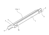
図1(a)、(b)に示す様に、本発明に係る棒熨斗瓦1、1a…にあっては、断面形状が箱熨斗瓦の側部と略同一になる陶磁器板で、緩やかに下方傾斜した断面弧状の熨斗部2と、該熨斗部2の内端上部に上方突設した固定突部3とを有し、熨斗部2の外端面である熨斗面4を、内方への傾斜面としている。固定突部3に釘孔5、5aを形成し、熨斗部2の内端面と固定突部3の内側面とを面一にして平面状の、後述する熨斗瓦固定材9との当接面6を形成し、該当接面6に上下方向全体にわたる溝7を形成している。
Hereinafter, embodiments for carrying out the present invention will be described with reference to the drawings.
As shown in FIGS. 1 (a) and 1 (b), the rod roof tiles 1, 1a... According to the present invention are ceramic plates whose cross-sectional shape is substantially the same as the side portions of the box roof tiles. A
次に、上記棒熨斗瓦1、1a…を使用した棟構造について説明する。
図2、3に示す様に、屋根下地Wにおける棟部Aに複数個の支持材8を所定間隔毎に立設し、該支持材8上に、棟部Aに沿って長い熨斗瓦固定材9を載架固定し、該熨斗瓦固定材9の各側面10、10a に複数の棒熨斗瓦1、1a…を、側面10、10a の長手方向に並列配置し固定した上下2段の熨斗列11、11a を形成し、隣接する熨斗列11、11a の上方の棒熨斗瓦1、1a…が下方の棒熨斗瓦1、1a…の上面に接地させずに相互間に隙間12を形成し、1段目の熨斗列11と、その直下の桟瓦Tとの間の面戸を漆喰、面戸瓦等により閉鎖し、各棒熨斗瓦1、1a…の溝7により熨斗瓦固定材9の側面10、10a との間に通気路13を形成している。
最上段である2段目の左右の熨斗列11a 、11a に跨ぐ様に冠瓦14、14a …を、熨斗列11a 、11a の棒熨斗瓦1、1a…の上面に接地させずに相互間に隙間15を開けて設置し、各冠瓦14、14a …は、貫通させた釘、ビス等の固定具16を熨斗瓦固定材9に打ち込んで該熨斗瓦固定材9に固定されている。
Next, the ridge structure using the above-mentioned
As shown in FIGS. 2 and 3, a plurality of
The
尚、図面上、各棒熨斗瓦1、1a…は、釘穴5、5aを貫通させた釘、ビス等の固定具17、17a を両側面10、10a に打ち込んで熨斗瓦固定材9に固定されている。
In the drawing, each
又、図面上、2列の熨斗列11、11a を有しているが、3列以上であっても良く、要するに複数列であれば良い。
又、熨斗瓦固定材9の両側面10、10a は階段状に形成され、その立ち上げ面部に棒熨斗瓦1、1a…が固定されているが、単なる平面であっても良い。
In the drawing, there are two
Further, both
次に、本発明に係る棒熨斗瓦を使用した棟構造の作用について説明する。
屋根裏の空気は、先ず棟部Aの隙間を通過して、熨斗瓦固定材9の下方の空間に流入し、続いて1段目の熨斗列11における各棒熨斗瓦1、1a…の溝7により熨斗瓦固定材9の側面10、10a との間に形成された通気路13を通って、2段の熨斗列11a との間に流入し、一部は隙間12から外部排出され、残りは更に2段目の熨斗列11a における通気路13を通って、冠瓦14、14a …との間に流入し隙間15から外部排出される。
Next, the operation of the ridge structure using the bar roof tile according to the present invention will be described.
The air in the attic first passes through the gap in the ridge A and flows into the space below the roof tile fixing material 9, and then the
1、1a… 棒熨斗瓦
2 熨斗部
3 固定突部
5、5a 釘孔
6 当接面
7 溝
8 支持材
9 熨斗瓦固定材
10、10a 側面
11、11a 熨斗列
12 隙間
13 通気路
14、14a … 冠瓦
15 隙間
A 棟部
T 桟瓦
W 屋根下地
1, 1a ...
10, 10a side
11, 11a
12 Clearance
13 Airway
14, 14a… Crown roof tile
15 Clearance A Building T Tile W W Roof base
Claims (2)
Priority Applications (1)
| Application Number | Priority Date | Filing Date | Title |
|---|---|---|---|
| JP2012096702A JP2013224538A (en) | 2012-04-20 | 2012-04-20 | Bar plain ridge tile and ridge structure using the same |
Applications Claiming Priority (1)
| Application Number | Priority Date | Filing Date | Title |
|---|---|---|---|
| JP2012096702A JP2013224538A (en) | 2012-04-20 | 2012-04-20 | Bar plain ridge tile and ridge structure using the same |
Publications (1)
| Publication Number | Publication Date |
|---|---|
| JP2013224538A true JP2013224538A (en) | 2013-10-31 |
Family
ID=49594766
Family Applications (1)
| Application Number | Title | Priority Date | Filing Date |
|---|---|---|---|
| JP2012096702A Pending JP2013224538A (en) | 2012-04-20 | 2012-04-20 | Bar plain ridge tile and ridge structure using the same |
Country Status (1)
| Country | Link |
|---|---|
| JP (1) | JP2013224538A (en) |
Cited By (1)
| Publication number | Priority date | Publication date | Assignee | Title |
|---|---|---|---|---|
| JP2016008414A (en) * | 2014-06-24 | 2016-01-18 | 請川 和英 | Ridge-tile installation structure |
Citations (6)
| Publication number | Priority date | Publication date | Assignee | Title |
|---|---|---|---|---|
| JPS61163823U (en) * | 1985-03-29 | 1986-10-11 | ||
| JPH04153452A (en) * | 1990-08-24 | 1992-05-26 | Chisso Corp | Dry type ridge provided with ventilating mechanism, and spacer to be used for this dry type ridge |
| JPH0492921U (en) * | 1990-12-28 | 1992-08-12 | ||
| JPH10183874A (en) * | 1996-12-27 | 1998-07-14 | Yoshitaka Yoshinari | Building ventilation structure |
| JP2003301564A (en) * | 2002-04-12 | 2003-10-24 | Ichio Tsuji | Roof tiles for tatami tiles, bonito tiles, and ridges |
| JP2003321903A (en) * | 2002-04-30 | 2003-11-14 | Yamamoto Yasunori | Dry seismic work |
-
2012
- 2012-04-20 JP JP2012096702A patent/JP2013224538A/en active Pending
Patent Citations (6)
| Publication number | Priority date | Publication date | Assignee | Title |
|---|---|---|---|---|
| JPS61163823U (en) * | 1985-03-29 | 1986-10-11 | ||
| JPH04153452A (en) * | 1990-08-24 | 1992-05-26 | Chisso Corp | Dry type ridge provided with ventilating mechanism, and spacer to be used for this dry type ridge |
| JPH0492921U (en) * | 1990-12-28 | 1992-08-12 | ||
| JPH10183874A (en) * | 1996-12-27 | 1998-07-14 | Yoshitaka Yoshinari | Building ventilation structure |
| JP2003301564A (en) * | 2002-04-12 | 2003-10-24 | Ichio Tsuji | Roof tiles for tatami tiles, bonito tiles, and ridges |
| JP2003321903A (en) * | 2002-04-30 | 2003-11-14 | Yamamoto Yasunori | Dry seismic work |
Cited By (1)
| Publication number | Priority date | Publication date | Assignee | Title |
|---|---|---|---|---|
| JP2016008414A (en) * | 2014-06-24 | 2016-01-18 | 請川 和英 | Ridge-tile installation structure |
Similar Documents
| Publication | Publication Date | Title |
|---|---|---|
| US1886962A (en) | Building construction | |
| US20110239548A1 (en) | Modular construction system | |
| JP5870383B2 (en) | Interstitial structure, building external structure, and construction method of building external structure | |
| JP2016130451A (en) | Coping ventilation component | |
| KR101210945B1 (en) | Root structure of traditional korean-style house | |
| JP6475999B2 (en) | Building ceiling structure | |
| JP5123685B2 (en) | Building eaves structure | |
| WO2007118916B1 (en) | Device for partitioning and closures of vertical type | |
| JP6133568B2 (en) | Base box fixing material, building structure using the base box fixing material | |
| JP6198598B2 (en) | Eave back ceiling structure | |
| KR102198690B1 (en) | How to install pavilion type pergola | |
| KR20140014761A (en) | Louver | |
| JP4588650B2 (en) | Ladle-shaped roof tiles, stacking structures in ridges using the roof tiles, and draining structures near the walls | |
| JP6077197B2 (en) | Standardized building | |
| RU152979U1 (en) | COMBINED WALL BUILDING ELEMENT FROM COMBINED LOG OR BAR | |
| JP5687919B2 (en) | Assembly building and construction method of assembly building | |
| JP5308168B2 (en) | Unit building | |
| JP2018112031A (en) | Floor structure and construction method of floor structure | |
| JP5951312B2 (en) | Building accessories | |
| JP6180915B2 (en) | Incombustible ventilation material | |
| JP5958984B1 (en) | Manufacturing method of wooden building based on grid design method | |
| JP7847517B2 (en) | Solar cell module | |
| JP5329982B2 (en) | Unit building | |
| JP3098530U (en) | Prevention of gap at the top of log house wall | |
| JP7007877B2 (en) | Parting structure of eaves top plate |
Legal Events
| Date | Code | Title | Description |
|---|---|---|---|
| A621 | Written request for application examination |
Free format text: JAPANESE INTERMEDIATE CODE: A621 Effective date: 20150420 |
|
| A977 | Report on retrieval |
Free format text: JAPANESE INTERMEDIATE CODE: A971007 Effective date: 20160215 |
|
| A131 | Notification of reasons for refusal |
Free format text: JAPANESE INTERMEDIATE CODE: A131 Effective date: 20160315 |
|
| A02 | Decision of refusal |
Free format text: JAPANESE INTERMEDIATE CODE: A02 Effective date: 20160927 |