JP2013203489A - Unwinding device of yarn - Google Patents
Unwinding device of yarn Download PDFInfo
- Publication number
- JP2013203489A JP2013203489A JP2012071635A JP2012071635A JP2013203489A JP 2013203489 A JP2013203489 A JP 2013203489A JP 2012071635 A JP2012071635 A JP 2012071635A JP 2012071635 A JP2012071635 A JP 2012071635A JP 2013203489 A JP2013203489 A JP 2013203489A
- Authority
- JP
- Japan
- Prior art keywords
- yarn
- raw material
- bobbin
- flyer
- guide
- Prior art date
- Legal status (The legal status is an assumption and is not a legal conclusion. Google has not performed a legal analysis and makes no representation as to the accuracy of the status listed.)
- Pending
Links
- 239000002994 raw material Substances 0.000 claims abstract description 123
- 239000000463 material Substances 0.000 claims abstract description 35
- 230000002093 peripheral effect Effects 0.000 claims description 22
- 241000226585 Antennaria plantaginifolia Species 0.000 claims description 14
- 239000000696 magnetic material Substances 0.000 claims description 2
- 238000004804 winding Methods 0.000 abstract description 20
- 241001155433 Centrarchus macropterus Species 0.000 abstract 2
- 238000011143 downstream manufacturing Methods 0.000 description 6
- 238000000034 method Methods 0.000 description 6
- 238000009434 installation Methods 0.000 description 5
- XEEYBQQBJWHFJM-UHFFFAOYSA-N Iron Chemical compound [Fe] XEEYBQQBJWHFJM-UHFFFAOYSA-N 0.000 description 2
- 239000004744 fabric Substances 0.000 description 2
- 230000005484 gravity Effects 0.000 description 2
- 238000009940 knitting Methods 0.000 description 2
- 239000002184 metal Substances 0.000 description 2
- 229910052751 metal Inorganic materials 0.000 description 2
- 239000011347 resin Substances 0.000 description 2
- 229920005989 resin Polymers 0.000 description 2
- 230000001133 acceleration Effects 0.000 description 1
- 238000013459 approach Methods 0.000 description 1
- 235000013351 cheese Nutrition 0.000 description 1
- 230000000694 effects Effects 0.000 description 1
- 239000013013 elastic material Substances 0.000 description 1
- 229910052742 iron Inorganic materials 0.000 description 1
- 230000005389 magnetism Effects 0.000 description 1
- 238000004519 manufacturing process Methods 0.000 description 1
- 239000007769 metal material Substances 0.000 description 1
- NJPPVKZQTLUDBO-UHFFFAOYSA-N novaluron Chemical compound C1=C(Cl)C(OC(F)(F)C(OC(F)(F)F)F)=CC=C1NC(=O)NC(=O)C1=C(F)C=CC=C1F NJPPVKZQTLUDBO-UHFFFAOYSA-N 0.000 description 1
- 230000002265 prevention Effects 0.000 description 1
- 230000010349 pulsation Effects 0.000 description 1
- 238000009958 sewing Methods 0.000 description 1
- 238000011144 upstream manufacturing Methods 0.000 description 1
Images


Landscapes
- Guides For Winding Or Rewinding, Or Guides For Filamentary Materials (AREA)
- Unwinding Of Filamentary Materials (AREA)
Abstract
Description
本発明は、糸の解舒装置に関するものである。 The present invention relates to a yarn unwinding device.
ストレートの筒形に形成された巻芯に糸を巻き付けた状態のもの(チーズ等と呼称されるが本明細書ではボビン巻なども含めて「糸巻原料」と言う)から糸を解舒する(巻き出す)ための装置として、従来、糸巻原料を水平支柱に突き刺して保持させ、糸巻原料の外周部に沿って周回するように設けたL型レバーで糸を案内しつつ、巻芯の延長線上に設けた案内ガイドへ向けて解舒させる装置が提案されている(特許文献1参照)。 The yarn is unwound from a state in which the yarn is wound around the core formed in a straight cylindrical shape (referred to as cheese or the like, but referred to as “bobbin winding” in this specification). As a device for unwinding), conventionally, the bobbin raw material is pierced and held by a horizontal support, and the yarn is guided by an L-shaped lever provided so as to circulate along the outer periphery of the bobbin raw material. There has been proposed a device for unwinding toward a guide guide provided in (see Patent Document 1).
この公知の解舒装置では、糸巻原料を水平支柱に突き刺して保持させている(以下では、この保持方式を「横置き」と言う)ことで、糸巻原料に対してその径方向外方へ糸を引き出すことができるものとしている。
そして、この横置き方式を採用すれば、糸巻原料の芯軸方向に沿って糸を引き出す古来の解舒方法(特許文献1の図2参照)に付随していた問題(糸巻原料に巻かれている糸と解舒する糸とが分離の際に擦れあって引っ掛かり、糸切れを起こす現象)を解消できるものと説明されている。
In this known unwinding device, the bobbin raw material is pierced and held by a horizontal support (hereinafter, this holding method is referred to as “horizontal placement”), whereby the yarn raw material is diametrically outward. To be able to pull out.
And if this horizontal placement system is adopted, the problem associated with the traditional unwinding method (see FIG. 2 of Patent Document 1) for drawing the yarn along the core axis direction of the bobbin material (winded on the bobbin material) It is explained that the phenomenon in which the yarn that is unwound and the yarn to be unwound are rubbed and caught when they are separated to cause a yarn breakage).
なお、糸巻原料を巻芯の一端側を支持するように立てて保持させた場合(以下では、この保持方式を「縦置き」と言う)においても、糸巻原料の芯軸方向に沿って(上方へ)糸を引き出していたことから、上記と同じ理由で糸切れの問題が起こっていて、特許文献1に開示の解舒装置では、この問題も解消できると指摘している。
Even when the bobbin raw material is held upright so as to support one end side of the core (hereinafter, this holding method is referred to as “longitudinal placement”), along the core axis direction of the bobbin raw material (upward F) Since the yarn was pulled out, the yarn breakage problem occurred for the same reason as described above, and it is pointed out that the unraveling device disclosed in
特許文献1に開示の解舒装置では、横置きとされた糸巻原料からL型レバーを介して案内ガイドへと導かれる糸のうち、L型レバーと案内ガイドとの間で糸が下方へ湾曲するように垂れ下がる現象が生じる。そのため、この下方湾曲した糸が横置きされた糸巻原料の上方を通過する際に、当該糸巻原料に接触することがあった。
また、L型レバーの周回軌道(円周軌道)のうち、周回の回転中心を通る鉛直線を境として、重力に逆らう領域(下死点から上死点へ向かう180°)では周速度が減速傾向を示し、反対に重力に倣う領域(上死点から下死点へ向かう180°)では周速度が加速傾向を示す、といった具合に速度変化が生じる。
In the unraveling device disclosed in
Also, of the L-shaped lever orbit (circular orbit), the peripheral speed decelerates in the region against gravity (180 ° from bottom dead center to top dead center) with the vertical line passing through the rotation center of rotation as the boundary. On the contrary, in the area following the gravity (180 ° from the top dead center toward the bottom dead center), the peripheral speed shows an acceleration tendency, and the speed change occurs.
すなわち、L型レバーの周速度には1回転の中に速度ムラが生じるので、この速度ムラが原因として糸の解舒速度にも遅速の脈動が生じることになる。のみならず、解舒される糸により生じるバルーンは糸巻原料と同心円とはならず、糸巻原料に接近(場合によっては接触)したり離反したりする歪な楕円状となる。これらのことから、極めて不安定な給糸状態となり、編み機の原料台に用いた場合は、編み生地での段差や斑を生じ、甚だしい場合には、むしろ糸切れを頻発させることになっていた。 In other words, since the circumferential speed of the L-shaped lever is uneven in speed during one rotation, this speed unevenness also causes a slow pulsation in the yarn unwinding speed. In addition, the balloon generated by the yarn to be unwound is not concentric with the bobbin raw material, but has a distorted ellipse shape that approaches (in some cases contacts) or separates from the bobbin raw material. From these facts, it became extremely unstable yarn feeding state, and when used as a raw material table of a knitting machine, steps and spots were generated in the knitted fabric, and in severe cases, thread breakage was frequently caused .
糸巻原料は生産効率の向上のために巻き量を多くするため、相当の重量になった原料を水平支柱に対して横向きに差し込む準備作業は、作業が面倒であると共に重労働になるという問題があった。
特に、フィラメント糸は毛羽が無いために、糸巻原料の外周面から糸がパラパラと解れて(ほぐれて)落ちるという特性を有しているが、この特性が要因となって上記問題は更に一層、深刻度を増したものとなっていた。
In order to improve the production efficiency of the bobbin winding material, the amount of winding is increased. Therefore, the preparation work in which the material having a considerable weight is inserted sideways with respect to the horizontal support has the problem that the work is troublesome and it becomes heavy labor. It was.
In particular, since the filament yarn has no fluff, it has the property that the yarn breaks apart (unwinds) from the outer peripheral surface of the bobbin raw material. It was of increasing severity.
本発明は、上記事情に鑑みてなされたものであって、縦置きした糸巻原料の外周面からパラパラと解れて落ちるような特性を有した糸であろうと、糸を一定速度で且つ安定して解舒できるものとして、糸切れ等の発生を未然に防止し、また糸巻原料のセット作業等についても従来の問題を解消できるようにした糸の解舒装置を提供することを目的とする。 The present invention has been made in view of the above circumstances, and even if the yarn has such a characteristic that it falls apart from the outer peripheral surface of the vertically placed bobbin raw material, the yarn can be stably fed at a constant speed. An object of the present invention is to provide a yarn unwinding device that can prevent unraveling of yarn breakage and the like, and that can solve the conventional problems in the setting operation of the bobbin winding material.
前記目的を達成するために、本発明は次の手段を講じた。
即ち、本発明に係る糸の解舒装置では、巻芯に糸が巻かれて成る糸巻原料を巻芯の一端側を支持するように立てた状態に支持する原料支持台と、前記原料支持台に支持される糸巻原料の芯中心を回転軸心とおいて前記糸巻原料の周囲を周回自在に設けられたフライヤーと、を有し、前記フライヤーには、前記糸巻原料から解舒される糸を当該糸巻原料の径方向外方へ引き出した後に前記糸巻原料の真上へ向けた仰角方向へ出射させる出射ガイドが設けられていることを特徴とする。
In order to achieve the above object, the present invention has taken the following measures.
That is, in the yarn unwinding device according to the present invention, a raw material support base that supports a bobbin raw material in which a yarn is wound around a core in a standing state so as to support one end side of the core, and the raw material support base A flyer provided around the pincushion raw material so as to be able to circulate around the pincushion raw material with the core center of the pincushion raw material supported on the rotation axis as the rotation center. It is characterized in that an exit guide is provided for emitting the pincushion raw material radially outward and then emitting the pincushion raw material in an elevation angle direction directly above the pincushion raw material.
なお、前記フライヤーにおいては、前記糸巻原料の外周面に対向する配置で設けられて前記糸巻原料から解舒される糸をフライヤーの外面側へ通過させる入射ガイドと、前記入射ガイドからフライヤーの外面側へ出た糸を当該入射ガイドよりも上方でフライヤーの内面側へ通過させる出射ガイドと、が設けられた構成であるとしてもよい。
前記フライヤーが周回する周回軌道内の少なくとも一カ所と当該フライヤーとの両者間に、フライヤーの周回動作に抵抗を生じさせて当該フライヤーを停止保持させる仮ブレーキ手段が設けられている構成とするのが好適である。
In the flyer, an incident guide provided in an arrangement facing the outer peripheral surface of the pincushion raw material and passing the yarn unwound from the pincushion raw material to the outer surface side of the fryer, and an outer surface side of the fryer from the incident guide An exit guide that allows the thread that has exited to pass to the inner surface side of the fryer above the entrance guide may be provided.
Temporary brake means is provided between at least one place in the orbit around which the flyer circulates and the flyer so as to generate resistance in the flyer's orbiting operation and stop and hold the fryer. Is preferred.
前記仮ブレーキ手段は、磁石とこの磁石に吸着する磁性体との組み合わせによって構成されたものとすればよい。
前記フライヤーの入射ガイドは、前記糸巻原料の外周面における縦方向中央部より低い位置に設けられているものとするのが好適である。
前記フライヤーは、前記原料支持台に支持される前記糸巻原料から前記入射ガイドへ通る糸を前記糸巻原料の外周面に対向して入射させる側片部を有したものとするのが好適である。
The temporary brake means may be constituted by a combination of a magnet and a magnetic material attracted to the magnet.
It is preferable that the incident guide of the flyer is provided at a position lower than the longitudinal central portion on the outer peripheral surface of the bobbin raw material.
It is preferable that the flyer has a side piece portion that allows a yarn passing from the bobbin material supported by the material support to the incident guide to be incident on an outer peripheral surface of the bobbin material.
前記フライヤーは、前記出射ガイドからフライヤーの内面側へ入った糸を前記原料支持台に支持される前記糸巻原料の真上へ向けた仰角方向へ出射させる上片部を有したものとするのが好適である。
前記原料支持台は、前記糸巻原料よりも径大に形成されていると共に、台上面に前記糸巻原料の支持によって圧縮可能となる緩衝層が設けられたものとするのが好適である。
The flyer has an upper piece portion that emits the yarn that has entered the inner surface of the fryer from the emission guide in an elevation direction directed directly above the spool material supported by the material support base. Is preferred.
The raw material support base is preferably formed to have a diameter larger than that of the bobbin raw material, and a buffer layer that can be compressed by supporting the bobbin raw material is provided on the top surface of the base.
本発明に係る糸の解舒装置は、縦置きした糸巻原料の外周面からパラパラと解れて落ちるような特性を有した糸であろうと、糸を一定速度で且つ安定して解舒できるものであり、糸切れ等の発生を未然に防止できる。また糸巻原料の準備作業等についても従来の問題を解消できるものである。 The yarn unwinding device according to the present invention is capable of stably unwinding a yarn at a constant speed, even if it is a yarn that has a characteristic of falling apart from the outer peripheral surface of a vertically placed spool material. Yes, yarn breakage and the like can be prevented from occurring. In addition, the conventional problem of the preparation of the bobbin material can be solved.
以下、本発明の実施の形態を、図面に基づき説明する。
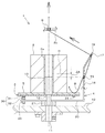
図1及び図2は、本発明に係る糸の解舒装置1を示している。また図3は、この解舒装置1の設置例を示している。この解舒装置1は、巻芯2aに糸2bが巻かれて成る糸巻原料2から糸2bを解舒する(巻き出す)ためのものであって、糸巻原料2を縦置きに支持する方式(巻芯2aの一端側を支持するように立てる方式)としている。
Hereinafter, embodiments of the present invention will be described with reference to the drawings.
1 and 2 show a yarn unwinding
なお、この解舒装置1は、1台だけを単独で設置するようにしてもよいが、多くの場合は、図3に示すように、取付テーブル10などに対して複数台が互いに所定間隔をおいて並ぶように設置する。各解舒装置1の設置位置には、解舒装置1よりも高い上方位置に、解舒した糸2bを下流側工程(例えば、小型のボビンへ巻き直す工程など)へ導くためのヤーンガイドGが設けられている。糸巻原料2は、その芯中心がヤーンガイドGの真下になるように設置する。
Note that only one unit of the
すなわち、本発明に係る解舒装置1は、糸巻原料2の芯軸方向に沿って上方のヤーンガ
イドGへ向けて糸2bを解舒するタイプである。
図1に示すように、この解舒装置1は、糸巻原料2を縦置きにして支持する原料支持台3と、この原料支持台3の周囲を周回自在となるように設けられたフライヤー4とを有している。
That is, the
As shown in FIG. 1, the
原料支持台3は、糸巻原料2の最大外径(糸2bが巻き出されていない最も太径のときの外径)よりも、更に径大の円板形に形成されたもので、糸巻原料2を支持したときにも、当該糸巻原料2の外周側へ張り出すようになっている。そのため、糸巻原料2の外周面から糸2bがパラパラと解れて(ほぐれて)落ちるようなことがあっても、この糸2bを原料支持台3が受け止められるようになっている。
The
この原料支持台3の台上面には、例えばスポンジやゴム、布帛等、糸巻原料2の支持によって圧縮可能となる緩衝層5が積層状に設けられている。この緩衝層5が設けられることで、原料支持台3に対する糸巻原料2の密着性を高めて、これら両者間に糸2bが食い込むことがないようにし、且つ解舒中の糸2bが原料支持台3(緩衝層5)に接触したときの滑りをよくして(摩擦抵抗を軽減させて)、解舒の支障とならないようにしている。
A
本実施形態において、原料支持台3は、取付テーブル10から上方突出する状態で固定された支持柱11により、取付テーブル10から浮き上がった状態に保持されたものとしてある。このように原料支持台3を浮き上げることで、支持柱11は、取付テーブル10と原料支持台3との上下間を貫通している部分に、フライヤー4を回転自在に取り付けるための旋回軸部12を形成させている。
In the present embodiment, the
また、支持柱11は原料支持台3の上方へ突出させてあり、この突出部分でガイド突起13を保持させてある。このガイド突起13は、糸巻原料2の巻芯2a内に嵌り、巻芯2aの内周面に接触する円筒形に形成されたもので、支持柱11、殊に旋回軸部12と同心となるように形成されている。そのため、このガイド突起13に糸巻原料2を嵌め込むようにすることによって、原料支持台3上での糸巻原料2の位置決め(センタリング)及びガタツキ防止を行える。
Further, the
なお、このガイド突起13は支持柱11(又は原料支持台3としてもよい)に対して固定してもよいが、支持柱11(又は原料支持台3)に対して着脱可能な構造とし、そのうえで外径の異なるものを複数サイズ準備しておくようにするとよい。このようにガイド突起13を着脱自在にすることで、巻芯2aの内径が異なる複数種の糸巻原料2に対応させることができる。
The
フライヤー4は、入射ガイド15を備える側片部16と、出射ガイド17を備える上片部18とを有している。また、前記したように本実施形態では、原料支持台3を支える支持柱11(旋回軸部12)を利用して、フライヤー4の回転を保持させるようになっている。そのためにフライヤー4は、旋回軸部12に対して回転自在に保持された回転アーム20を有したものとしてあり、この回転アーム20の先端(径方向外方)にL型となる状態で側片部16を立ち上げた構造としてある。
The
回転アーム20には、旋回軸部12に対する回転抵抗を軽減するためにベアリング等を内蔵した軸受部21を設けてある。なお、この軸受部21を省略して、回転アーム20に設けた回転孔を直接、旋回軸部12に差し込んで回転自在とさせるといった簡易構造を採用してもよいことは言うまでもない。
側片部16は、原料支持台3に支持される糸巻原料2に対し、その外周面と並行する状態となるように縦方向に設けられたもので、回転アーム20の長さで、原料支持台3と接触しない位置(外周側)となるように配置されている。
The
The
すなわち、この側片部16は、回転アーム20の回転に伴って原料支持台3の周囲を周回することによっても、常に、糸巻原料2の外周面に対向し、且つ並行した状態を保持するものとなる。なお、側片部16の周回動作は支持柱11の旋回軸部12を回転軸として行われるものであり、旋回軸部12と糸巻原料2とは、支持柱11に保持されるガイド突起13によってセンタリングされるので、側片部16は、原料支持台3に支持される糸巻原料2の芯中心を回転軸心とおいて周回するものであることは言うまでもない。
That is, the
このようなことから、糸巻原料2から糸2bを径方向外方へ引き出すようにしたときに
、この側片部16に設けられた入射ガイド15に対して、糸2bを、糸巻原料2の外周面に対向した状態として入射させ、フライヤー4(側片部16)の外面側へ導き出すことができる。
この側片部16に対し、入射ガイド15は、糸巻原料2の外周面における縦方向中央部H(巻芯2aの全長の1/2となる位置)より低くなる位置(Δh寸法だけ下)に設けられている。これは次の理由による。
For this reason, when the
With respect to the
すなわち、糸巻原料2から解舒中の糸2bは、下側凸の湾曲を伴ったバルーンB(糸巻原料2のまわりに膨れる弛み)を生ずることになるが、このバルーンBを引き上げながら入射ガイド15へ導くときの引き上げ高さを低く抑えることで、バルーンBを小さく押さえることにより、糸2bに作用する負担(張力)を軽減させる、というのがその理由である。
That is, the
なお、糸巻原料2を形成している糸2bが、フィラメント糸である場合は、糸2bに手羽が無いことに加えて、糸巻原料2の巻芯2aとしてストレート筒形のものが用いられていることも相まって、糸巻原料2を縦置きすることによってその外周面から糸2bがパラパラと解れて落ちるということが起こる。このような糸2bでは、前記したバルーンBについても原料支持台3に接触する量が多くなる傾向があるので、前記した入射ガイド15の配置を採用することが、より一層重要となる。
In addition, when the
Δh寸法を具体的にどの程度にするかは、糸2bの糸種、回転アーム20の回転半径及び回転速度などに応じて適宜変更するのがよい。ただ、Δh寸法を過度に大きくすると(入射ガイド15を下方へ下げすぎると)、バルーンBが原料支持台3に接触する量が更に多くなるおそれがあり、これを避けるために原料支持台3の径大化などが必要になる。また、糸巻原料2の上部位置から糸2bが解舒されるときには、入射ガイド15へ向かう糸2bが下り傾斜角も急角度となって、入射ガイド15を通過する糸2bに急角度の折れ曲がりが生じ、これが解舒抵抗に繋がるおそれもある。これらのことから、Δh寸法は、5〜20mm(より好ましくは10mm前後)などとするのが好ましい。
The specific level of the Δh dimension may be appropriately changed according to the yarn type of the
一方、フライヤー4の上片部18は、上端側ほど糸巻原料2から離れる方向となるように斜めに設けられたもので、側片部16の上端部に対して「く」字状に屈曲形成されている。従って、この上片部18に設けられる出射ガイド17に対し、フライヤー4(上片部18)の外面側からフライヤー4(上片部18)の内面側へ向けて糸2bを通したとき、この糸2bを、原料支持台3に支持される糸巻原料2の真上へ向けた仰角方向へ出射させることができる。
On the other hand, the
この上片部18に対し、出射ガイド17を設ける位置(原料支持台3からの高さや上片部18の傾斜角)は、出射ガイド17から出た糸2bが、解舒装置1の上方に設けられたヤーンガイドGへ向かう間に、原料支持台3に支持される糸巻原料2に引っ掛かることがないようにできることを目安(糸2bの出射角度(=仰角)をどの程度にするかの目安)として配置してある。
With respect to the
なお、入射ガイド15や出射ガイド17は、いずれも、糸2bを通すための孔開き部材であって、糸2bとの摩擦を可及的に小さく抑えることのできる樹脂や金属等により形成されており、糸2bの解舒抵抗を抑制し、また糸2bが擦れ等を原因として毛羽の発生や切れやすくなるのを防止できるようにしたものである。
但し、側片部16や上片部18の形成素材として、糸2bとの摩擦を可及的に小さく抑えることのできる樹脂や金属等を用いるようにし、これら側片部16や上片部18に貫通孔を形成させることにより、この貫通孔で、入射ガイド15や出射ガイド17を形成させることができる(別部材としての孔開き部材を省略することができる)。
Each of the
However, as a material for forming the
以上、詳説したように、入射ガイド15を備える側片部16と、出射ガイド17を備える上片部18とを有して成るフライヤー4では、原料支持台3に縦置き支持された糸巻原料2から解舒される糸2bを糸巻原料2の外周面に対向する配置の入射ガイド15へ通してフライヤー4(側片部16)の外面側へ出し、フライヤー4の外面側では、入射ガイド15よりも上方に配置の出射ガイド17へ導いて、この出射ガイド17から再びフライヤー4(上片部18)の内面側へ糸2bを通すようになっている。
As described above in detail, in the
そして、この出射ガイド17を出た糸2bは、解舒装置1の上方に設けられたヤーンガイドGを介して、下流側工程(例えば、小型のボビンへ巻き直す工程など)へ送り出されるようになっている。
なお、解舒装置1は、原料支持台3に支持される糸巻原料2の芯中心(支持柱11及び旋回軸部12の中心であり且つフライヤー4の回転軸芯である)が、ヤーンガイドGの真下になるように設置しておくものとする。
Then, the
In the unwinding
上記のように解舒装置1の下流側工程へ向けて糸2bの給糸が開始されると、ヤーンガイドG、出射ガイド17、入射ガイド15を通過する糸2bに引き出し駆動が付与されることになり、原料支持台3上の糸巻原料2には、糸2bが解舒される作用(巻き出し力)が伝わるようになる。この解舒作用を受けて、フライヤー4は旋回軸部12を中心として原料支持台3の周囲を周回移動するようになり、以後、このようなフライヤー4の周回動作が継続しつつ、同心円状のバルーンBを形成させながら糸2bの解舒が行われるものである。
When the
ところで、本発明に係る解舒装置1では、フライヤー4が周回動作をする構成としたことに対して仮ブレーキ手段30を具備させたものとなっている。
この仮ブレーキ手段30は、必要に応じてフライヤー4を停止保持させることができるようにしたものであって、フライヤー4が周回する周回軌道内の少なくとも一カ所と、フライヤー4との両者間に、フライヤー4の周回動作に抵抗(ブレーキ作用)を生じさせる構成となっている。
By the way, in the
The temporary brake means 30 is configured to be able to stop and hold the
具体的に、仮ブレーキ手段30は、磁石31とこの磁石31に吸着する磁性体32との組み合わせとして構成してある。ここにおいて、磁性体32は、磁石31と接近したときに磁性を帯びる素材を言うものとし、鉄などの金属材はもとより、磁石である場合をも含むものとする。
本実施形態では、図2に示すように、磁石31は、原料支持台3に対して、その外周部における周方向2箇所で下向き(原料支持台3の裏面側)に磁力を発生させる状態に設けてある。2個の磁石31における周方向の相互間隔は180°としてある。磁石31は1箇所だけに設けてもよいし、逆に、3箇所以上に設けてもよい。ただ、設ける箇所を多くすればするほどブレーキ作用も強くなるので、フライヤー4の周回性能とブレーキ作用との関係において磁石31の設置箇所数を調整する必要がある。
Specifically, the temporary brake means 30 is configured as a combination of a
In the present embodiment, as shown in FIG. 2, the
これに対し、磁性体32は、フライヤー4の回転アーム20を、側片部16とは反対方向へ延長させて、磁石31の真下を通過するようになる部位1箇所に対し、上方突出状に設けてある。磁性体32を上方突出状に設けるために、ボルトを回転アーム20に螺合し、ナット33でダブルナット作用を生じさせて固定する簡易構造を採用してある。
磁性体32を形成しているボルトは、回転アーム20に対する螺合度合いを変えることでその上方突出量を調整することができるものであり、この上方突出量の調整で、磁石31と磁性体32との間に生じる吸引力を調整することが簡単に行えるという利点がある。
On the other hand, the
The bolts forming the
磁石31と磁性体32との間に生じさせる吸引力は、糸巻原料2から糸2bを引き出す力でフライヤー4が容易に周回動作できる(周回動作を邪魔しない)ものであり、そのうえで、糸2bに引き出し力が作用していない状態ではフライヤー4の周回動作を停止保持させることができることを目安として、調整する。
このような構成の仮ブレーキ手段30を備えているため、フライヤー4の周回位置につき、磁性体32が磁石31に接近して吸引される位置に合わせるようにすれば、フライヤー4の周回動作を停止させることができる。
The attraction force generated between the
Since the provisional brake means 30 having such a configuration is provided, if the
そのため、例えば万が一、糸2bの解舒中に下流側工程で給糸が止まったような場合にあって、ヤーンガイドG、出射ガイド17、入射ガイド15を通過する糸2bに引き出し駆動が付与されなくなると、フライヤー4は仮ブレーキ手段30の作用を受けて周回動作を直ちに停止することになる。
すなわち、フライヤー4が慣性により周回動作をすることが無くなるので、フライヤー4の慣性周回動作を原因として、原料支持台3上の糸巻原料2から糸2bが引き千切られる(糸切れする)ということがない。
Therefore, for example, in the event that the yarn supply stops in the downstream process during the unwinding of the
That is, since the
加えて、原料支持台3に対して糸巻原料2を縦置きセットする場合にあって、糸巻原料2から巻き出した糸2bを入射ガイド15、出射ガイド17、ヤーンガイドGへ通し、下流側工程へ張り渡すようにする準備作業が必要になるが、図3に示したように、多数の糸巻原料2から一斉に解舒を行うに際して、各解舒装置1でフライヤー4が勝手に周回方向に動作するのを仮ブレーキ手段30の作用で阻止できることになる。
In addition, when the bobbin
すなわち、この準備作業中に各解舒装置1でフライヤー4が勝手に周回方向に動作することが原因で、原料支持台3上の糸巻原料2から糸2bが引き千切られる(糸切れする)ということがない。
このように、本発明に係る解舒装置1では、糸巻原料2を縦置きにしたうえでその周囲にフライヤー4を周回動作させ、このフライヤー4に設けた出射ガイド17を介して糸2bの解舒を行う方式としているものであり、フライヤー4(出射ガイド17)は等速の周回動作を行い、安定的な給糸が可能となる。従って、糸2bが、縦置きした糸巻原料2の外周面からパラパラと解れて落ちるような特性を有したものであろうと、糸2bを一定速度で且つ安定して解舒できるものであって、糸切れ等の発生を未然に防止できる。
That is, it is said that the
As described above, in the unwinding
また、仮ブレーキ手段30による上記の糸切れ作用が得られるので、解舒装置1での糸切れを原因とするような下流側工程での作業効率の低下や生産品の歩留まり低下などを徹底して防止できるものとなっている。
なお、言うまでもなく、本発明に係る解舒装置1では糸巻原料2を縦置きする方式であるので、横置き方式が有していたようなセット作業の不便も当然に払拭されているものである。
Further, since the above-described yarn breakage action by the temporary brake means 30 can be obtained, it is possible to thoroughly reduce the work efficiency in the downstream process such as the yarn breakage in the unwinding
Needless to say, since the unwinding
図4は、本発明に係る解舒装置1の第2実施形態を示している。
この第2実施形態の解舒装置1では、原料支持台3を支持するための支持柱11が糸巻原料2の上端側まで届く長さとして形成されており、この支持柱11の上端部に対して、旋回軸部12を着脱できるようにしてある。そして、この旋回軸部12に、軸受部21を介してフライヤー4の回転アーム20が回転自在に保持されている。
FIG. 4 shows a second embodiment of the unwinding
In the unwinding
フライヤー4は、回転アーム20の径方向端部から下方へ屈曲形成された側片部16を有し、この側片部16に入射ガイド15が設けられていると共に、回転アーム20の同じ端部から上方斜め外方へ向けて屈曲形成された上片部18を有し、この上片部18に出射ガイド17が設けられたものとなっている。
また、この第2実施形態の解舒装置1において、仮ブレーキ手段30は、側片部16の下端外面に磁石31が設けられ、フライヤー4が周回動作する外側となる位置に、磁性体32が設けられた構成となっている。
The
In the unwinding
このような構成の一部に違いを有している第2実施形態の解舒装置1においても、フライヤー4や仮ブレーキ手段30によって生起される作用効果は第1実施形態と略同様であり、ここでの詳説は省略する。
ところで、本発明は、前記各実施形態に限定されるものではなく、実施の形態に応じて適宜変更可能である。
Also in the
By the way, the present invention is not limited to the above-described embodiments, and can be appropriately changed according to the embodiments.
例えば、原料支持台3は円板形にすることが限定されるものではなく、糸巻原料2を縦置きに支持できるものであれば、どのような形体(平面形が角形であるものや、板状ではなく台座ブロック的に形成されたものなど)であってもよい。
また、原料支持台3は、取付テーブル10から浮き上がった状態で支持することが限定されるものではなく、取付テーブル10に隙間無く設置する構造や、取付テーブル10と一体(兼用)とする構造としてもよい。
For example, the
In addition, the
解舒装置1の設置位置(下流側工程が何であるか)は限定されるものではなく、例えば、編機や縫製機などを設置した工程に対してその上流側に本発明に係る解舒装置1を設置するようにしてもよい。
第1実施形態で説明した仮ブレーキ手段30において、磁石31を取付テーブル10の上面に設け、磁性体32を、フライヤー4の回転アーム20に対して磁石31の真上を通過するようになる部位で下方突出状に設けるようにしてもよい。また、磁石31を複数箇所に設け、磁性体32を1箇所に設けているが、これとは反対に磁石31を1箇所に設け
、磁性体32を複数箇所に設けるようにしてもよい。
The installation position of the unwinding device 1 (what the downstream process is) is not limited. For example, the unwinding apparatus according to the present invention is provided upstream of the process in which a knitting machine, a sewing machine, or the like is installed. 1 may be installed.
In the temporary brake means 30 described in the first embodiment, the
また、第1実施形態で説明した仮ブレーキ手段30において、フライヤー4が周回する周回軌道内に磁性体32を設け、フライヤー4に磁石31を設けるようにしてもよい。これと同様に、第2実施形態で説明した仮ブレーキ手段30においては、フライヤー4が周回する周回軌道内に磁石31を設け、フライヤー4に磁性体32を設けるようにしてもよい。
Moreover, in the temporary brake means 30 demonstrated in 1st Embodiment, the
第1実施形態及び第2実施形態で説明した仮ブレーキ手段30において、磁石31は電磁石としてもよい。このようにすることで、磁石31のオンオフ切り換えによってフライヤー4の停止時期を所望タイミングに合わせて制御することができる。
更に、仮ブレーキ手段30は、フライヤー4が周回する周回軌道内にゴム板等の弾性材で形成されたストッパ片を設け、フライヤー4又はフライヤー4に別付けした部材が、ストッパ片と接触干渉するような構成としてもよい。当然に、ストッパ片をフライヤー4に設け、フライヤー4が周回する周回軌道内に、ストッパ片と接触干渉する部材を設けるような構成としてもよい。
In the temporary brake means 30 described in the first embodiment and the second embodiment, the
Further, the temporary brake means 30 is provided with a stopper piece formed of an elastic material such as a rubber plate in a circular track around which the
1 解舒装置
2 糸巻原料
2a 巻芯
2b 糸
3 原料支持台
4 フライヤー
5 緩衝層
10 取付テーブル
11 支持柱
12 旋回軸部
13 ガイド突起
15 入射ガイド
16 側片部
17 出射ガイド
18 上片部
20 回転アーム
21 軸受部
30 仮ブレーキ手段
31 磁石
32 磁性体
33 ナット
B バルーン
G ヤーンガイド
DESCRIPTION OF
Claims (8)
前記原料支持台に支持される糸巻原料の芯中心を回転軸心とおいて前記糸巻原料の周囲を周回自在に設けられたフライヤーと、を有し、
前記フライヤーには、
前記糸巻原料から解舒される糸を当該糸巻原料の径方向外方へ引き出した後に前記糸巻原料の真上へ向けた仰角方向へ出射させる出射ガイドが設けられている
ことを特徴とする糸の解舒装置。 A raw material support base for supporting a bobbin raw material in which a thread is wound around a core in a standing state so as to support one end side of the core;
A flyer provided around the pincushion material around the center of rotation of the pincushion material supported by the material support;
The flyer includes
An exit guide is provided for allowing the yarn to be unwound from the bobbin raw material to be drawn radially outward of the bobbin raw material and then emitting the yarn in an elevation direction directly above the bobbin raw material. Unraveling device.
前記原料支持台に支持される糸巻原料の芯中心を回転軸心とおいて前記糸巻原料の周囲を周回自在に設けられたフライヤーと、を有し、
前記フライヤーには、
前記糸巻原料の外周面に対向する配置で設けられて前記糸巻原料から解舒される糸をフライヤーの外面側へ通過させる入射ガイドと、
前記入射ガイドからフライヤーの外面側へ出た糸を当該入射ガイドよりも上方でフライヤーの内面側へ通過させる出射ガイドと、
が設けられていることを特徴とする糸の解舒装置。 A raw material support base for supporting a bobbin raw material in which a thread is wound around a core in a standing state so as to support one end side of the core;
A flyer provided around the pincushion material around the center of rotation of the pincushion material supported by the material support;
The flyer includes
An incident guide provided in an arrangement facing the outer peripheral surface of the bobbin raw material and passing the yarn unwound from the bobbin raw material to the outer surface side of the flyer;
An exit guide that passes the yarn from the entrance guide toward the outer surface of the fryer to the inner surface side of the fryer above the entrance guide;
A yarn unwinding device characterized in that is provided.
Priority Applications (1)
| Application Number | Priority Date | Filing Date | Title |
|---|---|---|---|
| JP2012071635A JP2013203489A (en) | 2012-03-27 | 2012-03-27 | Unwinding device of yarn |
Applications Claiming Priority (1)
| Application Number | Priority Date | Filing Date | Title |
|---|---|---|---|
| JP2012071635A JP2013203489A (en) | 2012-03-27 | 2012-03-27 | Unwinding device of yarn |
Publications (1)
| Publication Number | Publication Date |
|---|---|
| JP2013203489A true JP2013203489A (en) | 2013-10-07 |
Family
ID=49523016
Family Applications (1)
| Application Number | Title | Priority Date | Filing Date |
|---|---|---|---|
| JP2012071635A Pending JP2013203489A (en) | 2012-03-27 | 2012-03-27 | Unwinding device of yarn |
Country Status (1)
| Country | Link |
|---|---|
| JP (1) | JP2013203489A (en) |
Cited By (6)
| Publication number | Priority date | Publication date | Assignee | Title |
|---|---|---|---|---|
| CN105858324A (en) * | 2016-03-31 | 2016-08-17 | 芜湖富春染织有限公司 | Portable yarn releasing device |
| CN107954252A (en) * | 2017-12-14 | 2018-04-24 | 国家电网公司 | A kind of curl cable laying tool |
| CN108178024A (en) * | 2017-12-28 | 2018-06-19 | 苏州朦井纺织科技有限公司 | A kind of textile machines textile yarn wire installation |
| CN112424100A (en) * | 2018-08-09 | 2021-02-26 | 日本Tmt机械株式会社 | Yarn winding machine |
| CN112850328A (en) * | 2021-03-19 | 2021-05-28 | 路佃泉 | Flexible supporting axial unwinding device for hank yarns |
| CN116880021A (en) * | 2023-06-02 | 2023-10-13 | 浙江东通光网物联科技有限公司 | High-speed yarn bundling machine |
-
2012
- 2012-03-27 JP JP2012071635A patent/JP2013203489A/en active Pending
Cited By (7)
| Publication number | Priority date | Publication date | Assignee | Title |
|---|---|---|---|---|
| CN105858324A (en) * | 2016-03-31 | 2016-08-17 | 芜湖富春染织有限公司 | Portable yarn releasing device |
| CN107954252A (en) * | 2017-12-14 | 2018-04-24 | 国家电网公司 | A kind of curl cable laying tool |
| CN108178024A (en) * | 2017-12-28 | 2018-06-19 | 苏州朦井纺织科技有限公司 | A kind of textile machines textile yarn wire installation |
| CN112424100A (en) * | 2018-08-09 | 2021-02-26 | 日本Tmt机械株式会社 | Yarn winding machine |
| CN112424100B (en) * | 2018-08-09 | 2022-07-22 | 日本Tmt机械株式会社 | Wire Winding Machine |
| CN112850328A (en) * | 2021-03-19 | 2021-05-28 | 路佃泉 | Flexible supporting axial unwinding device for hank yarns |
| CN116880021A (en) * | 2023-06-02 | 2023-10-13 | 浙江东通光网物联科技有限公司 | High-speed yarn bundling machine |
Similar Documents
| Publication | Publication Date | Title |
|---|---|---|
| US10208411B2 (en) | Thread feeding device for torchon lace machine | |
| JP2015040116A (en) | Textile machine | |
| EP1717182B1 (en) | Yarn slack eliminating device in textile machine | |
| TWI765167B (en) | silk winding machine | |
| CN216272388U (en) | Paying-off machine | |
| CN223422138U (en) | Yarn tension linear change control mechanism and winding machine | |
| CN101448988B (en) | Active yarn guide with a movable yarn feeding ring | |
| JP2012001857A (en) | Twisting machine and method of producing twisted doubled yarn using twisting machine | |
| CN204676230U (en) | A kind of Fancy Yarns device | |
| CN107022821A (en) | A kind of processing unit (plant) of wrap yarn | |
| JP2020125188A (en) | Device for feeding long objects | |
| CN210480413U (en) | Synchronous pay-off is used in spinning processing with tension regulatory function | |
| CN212450065U (en) | Automatic winding machine | |
| JP2024122851A (en) | Yarn Winding Machine | |
| CN213708678U (en) | High-performance horizontal yarn carrying spindle for weaving fibers by braiding machine | |
| CN207726522U (en) | A kind of coiling apparatus with brake function | |
| CN112160069A (en) | A yarn-carrying spindle for braiding machine using magnetic damping to control yarn bobbin pay-off tension | |
| CN111108238B (en) | Yarn twisting machine | |
| CN221759150U (en) | Wire cylinder positioning device | |
| CN222809667U (en) | Yarn rack for yarn feeding of circular knitting machine | |
| CN213203372U (en) | Spindle of superfine wire braiding machine | |
| JP2004107007A (en) | Bobbin rewinder | |
| JP2000154452A (en) | Spindle holder in yarn feeder of torsion lace machine | |
| TW202022185A (en) | Thread breaking protection device of circular loom capable of avoiding the rotation of the reel when the weft thread is broken | |
| CN216662020U (en) | Spandex unwinding device |